RU2102629C1 - Method of and device for starting internal combustion engine from cold - Google Patents
Method of and device for starting internal combustion engine from cold Download PDFInfo
- Publication number
- RU2102629C1 RU2102629C1 RU93058385/06A RU93058385A RU2102629C1 RU 2102629 C1 RU2102629 C1 RU 2102629C1 RU 93058385/06 A RU93058385/06 A RU 93058385/06A RU 93058385 A RU93058385 A RU 93058385A RU 2102629 C1 RU2102629 C1 RU 2102629C1
- Authority
- RU
- Russia
- Prior art keywords
- engine
- during
- stage
- exhaust system
- starting
- Prior art date
Links
Images
Classifications
-
- F—MECHANICAL ENGINEERING; LIGHTING; HEATING; WEAPONS; BLASTING
- F02—COMBUSTION ENGINES; HOT-GAS OR COMBUSTION-PRODUCT ENGINE PLANTS
- F02N—STARTING OF COMBUSTION ENGINES; STARTING AIDS FOR SUCH ENGINES, NOT OTHERWISE PROVIDED FOR
- F02N19/00—Starting aids for combustion engines, not otherwise provided for
- F02N19/02—Aiding engine start by thermal means, e.g. using lighted wicks
-
- F—MECHANICAL ENGINEERING; LIGHTING; HEATING; WEAPONS; BLASTING
- F02—COMBUSTION ENGINES; HOT-GAS OR COMBUSTION-PRODUCT ENGINE PLANTS
- F02D—CONTROLLING COMBUSTION ENGINES
- F02D9/00—Controlling engines by throttling air or fuel-and-air induction conduits or exhaust conduits
- F02D9/04—Controlling engines by throttling air or fuel-and-air induction conduits or exhaust conduits concerning exhaust conduits
-
- F—MECHANICAL ENGINEERING; LIGHTING; HEATING; WEAPONS; BLASTING
- F02—COMBUSTION ENGINES; HOT-GAS OR COMBUSTION-PRODUCT ENGINE PLANTS
- F02D—CONTROLLING COMBUSTION ENGINES
- F02D9/00—Controlling engines by throttling air or fuel-and-air induction conduits or exhaust conduits
- F02D9/02—Controlling engines by throttling air or fuel-and-air induction conduits or exhaust conduits concerning induction conduits
- F02D2009/0201—Arrangements; Control features; Details thereof
- F02D2009/0249—Starting engine, e.g. closing throttle in Diesel engine to reduce starting torque
Abstract
Description
Настоящее изобретение касается способа холодного пуска двигателя внутреннего сгорания поршневого типа и устройства для осуществления этого способа. The present invention relates to a method for cold starting a piston type internal combustion engine and apparatus for implementing this method.
Во время холодного запуска двигателя внутреннего сгорания поршневого типа имеет место неполное сгорание топлива, подразумевающее нежелательно высокий выброс углеводородов вместе с другими компонентами. Это происходит при любой температуре окружающей среды, но увеличивается по мере снижения температуры окружающей среды. Важно поэтому достичь нормальной рабочей температуры. Наиболее распространенный способ состоит в организации предварительного подогрева впускного воздуха для двигателя, для чего требуется энергоемкий электронагревательный элемент, занимающий место при установке во впускном трубопроводе. During the cold start of a piston-type internal combustion engine, incomplete combustion of the fuel takes place, implying an undesirably high emission of hydrocarbons along with other components. This occurs at any ambient temperature, but increases as the ambient temperature decreases. It is therefore important to achieve normal operating temperature. The most common way is to pre-heat the intake air for the engine, which requires an energy-intensive electric heating element that takes up space when installed in the intake manifold.
Известен способ холодного пуска двигателя внутреннего сгорания поршневого типа, заключающийся в том, что в течение первого этапа во время прокручивания коленчатого вала двигателя осуществляют блокировку подачи топлива в камеры сгорания двигателя на протяжении заранее заданного количества оборотов вала двигателя, вследствие чего в двигателе сжимают воздух для прогрева камер сгорания генерируемой теплотой сжатия, и в течение второго этапа при дальнейшем прокручивании вала осуществляют подачу топлива до тех пор, пока не появится воспламенение. A known method of cold starting a piston-type internal combustion engine, which consists in the fact that during the first stage during the crankshaft of the engine, the fuel supply to the combustion chambers is blocked for a predetermined number of revolutions of the engine shaft, as a result of which air is compressed in the engine for heating combustion chambers with generated heat of compression, and during the second stage, with further rolling of the shaft, fuel is supplied until ignition occurs Menen.
Известно также устройство для осуществления холодного пуска двигателя внутреннего сгорания поршневого типа, содержащее стартер для прокручивания коленчатого вала двигателя и блок управления, который выполнен таким образом, что в течение первого этапа подает управляющий сигнал, осуществляющий блокировку подачи топлива в двигатель на протяжении заранее заданного количества оборотов вала двигателя, а в течение второго этапа прерывает блокировку. It is also known a device for cold starting a piston type internal combustion engine, comprising a starter for cranking the engine crankshaft and a control unit that is configured in such a way that during the first stage it provides a control signal that blocks the fuel supply to the engine for a predetermined number of revolutions motor shaft, and during the second stage interrupts the lock.
Задачей настоящего изобретения является решение отмеченных выше проблем запуска двигателя экономичным и эффективным путем таким образом, чтобы прогрев двигателя происходил, по возможности, быстро и даже без нагревательного элемента, размещенного на впуске в двигатель. The objective of the present invention is to solve the above problems of starting the engine in an economical and efficient way so that the engine warms up as quickly as possible and even without a heating element located at the inlet of the engine.
Поставленная задача решается там, что в способе холодного пуска двигателя внутреннего сгорания поршневого типа, заключающемся в том, что в течение первого этапа во время прокручивания коленчатого вала двигателя осуществляют блокировку подачи топлива в камеры сгорания двигателя на протяжении заранее заданного количества оборотов вала двигателя, вследствие чего в двигателе сжимают воздух для прогрева камер сгорания генерируемой теплотой сжатия, и в течение второго этапа при дальнейшем прокручивании вала осуществляют подачу топлива до тех пор, пока не появится воспламенение, согласно изобретению на первом этапе дополнительно проводят дросселирование выпуска, вследствие чего в системе выпуска устанавливают противодавление. The problem is solved there, that in the method of cold start of a piston type internal combustion engine, which consists in the fact that during the first stage during the crankshaft of the engine, the fuel supply to the combustion chambers is blocked for a predetermined number of revolutions of the engine shaft, as a result of which air is compressed in the engine to warm the combustion chambers with the generated heat of compression, and during the second stage, with further rolling of the shaft, fuel is supplied to until ignition appears, according to the invention, at the first stage, an additional throttling of the outlet is carried out, as a result of which backpressure is established in the exhaust system.
Поставленная задача решается также тем, что дросселирование выпуска проводят перед прокручиванием вала двигателя. The problem is also solved by the fact that the throttling of the exhaust is carried out before scrolling the motor shaft.
Поставленная задача решается тем, что устройство для осуществления холодного пуска двигателя внутреннего сгорания поршневого типа, содержащее стартер для прокручивания коленчатого вала двигателя и блок управления, который выполнен таким образом, что в течение первого этапа подает управляющий сигнал, осуществляющий блокировку подачи топлива в двигатель на протяжении заранее заданного количества оборотов вала двигателя, а в течение второго этапа прерывает блокировку, согласно изобретению, снабжено дроссельным узлом в выпускной системе двигателя, а блок управления выполнен с возможностью удержания дроссельного узла в дросселирующем положении для того, чтобы создать в выпускной системе противодавление во время прокручивания вала двигателя в течение первого этапа. The problem is solved in that a device for cold starting a piston type internal combustion engine, comprising a starter for cranking the engine crankshaft and a control unit that is configured in such a way that during the first stage it provides a control signal that blocks the fuel supply to the engine for a predetermined number of revolutions of the motor shaft, and during the second stage breaks the lock, according to the invention, is equipped with a throttle assembly in the exhaust system e engine, and the control unit is adapted to hold the throttle device in the throttling position to create a backpressure in the exhaust system during cranking of the engine shaft during the first step.
Поставленная задача решается также тем, что блок управления выполнен с возможностью удержания дроссельного узла в дросселирующем положении перед воздействием на стартер таким образом, чтобы противодавление появлялось в выпускной системе по мере прокручивания вала двигателя. The problem is also solved by the fact that the control unit is configured to hold the throttle assembly in the throttle position before acting on the starter so that back pressure appears in the exhaust system as the engine shaft scrolls.
Поставленная задача решается также тем, что клапан дроссельного узла снабжен подвижным поршнем, подпружиненным таким образом, что дроссельный узел старается удержать положение дросселирования. The problem is also solved by the fact that the valve of the throttle assembly is equipped with a movable piston, spring-loaded so that the throttle assembly tries to maintain the throttle position.
Поставленная задача решается также тем, что замок зажигания двигателя выполнен в виде первого положения, при котором дроссельный узел приводят в действие, и второго положения, при котором приводят в действие стартер двигателя. The problem is also solved by the fact that the engine ignition lock is made in the form of a first position at which the throttle assembly is actuated and a second position at which the engine starter is driven.
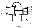
Фиг. 1 показывает схематично устройство холодного пуска по настоящему изобретению, согласно первому варианту реализации, в то время, как, фиг. 2 - схематичное изображение части устройства по второму варианту реализации. FIG. 1 shows schematically the cold start device of the present invention according to the first embodiment, while, FIG. 2 is a schematic illustration of a portion of a device according to a second embodiment.
В устройстве, согласно изобретению, предпочтительно, как это показано на фиг. 1 и 2, предусмотрен дроссельный узел 1, который размещен в выпускной системе 2 двигателя внутреннего сгорания поршневого типа, например, между выпускным трубопроводом и выхлопной трубой. Дроссельный узел представляет собой клапан 3, который размещен с возможностью регулирования между полностью закрытым положением, при котором выпуск полностью перекрыт, и полностью открытым положением, при котором дроссельное устройство не вносит изменения в перепад давления. При закрытом положении дроссельный узел может полностью перекрывать выпуск двигателя, при этом клапан 3 или посадочное седло 4 плотно закрыты. Альтернативно, в клапане может быть предусмотрено сквозное отверстие таким образом, что выпуск может быть перекрыт неподвижно. Дроссельный узел управляется посредством регулирующей части 5, которая, например, пневматически регулируется от пневмосистемы, принадлежащей автомобилю, вследствие чего регулировочная часть снабжена подпружиненным поршнем 7, подвижным в пневмоцилиндре 8, который действует напрямую и сообщен с пневмоисточником через электрически-управляемый соленоидом клапан 9. Все это подключено к регулировочному блоку 10, который совместно с другими функциями предназначен для управления дроссельным узлом. Вариант реализации согласно фиг. 1 показывает дроссельный узел прямого действия, подразумевающий, что пружина сжатия 6 действует для установки клапана в открытое состояние, регулирование клапана достигается тем, что переменное давление воздуха в пневмоцилиндре воздействует на поршень с противоположной стороны относительно пружины. Таким образом, максимальное положение дросселя достигается тогда, когда усилие, действующее на поршень от давления воздуха, больше давления пружины. Выполнение согласно фиг. 2 показывает устройство обратного действия, где пружина действует на поршень 7 в противоположном направлении, т.е. пытается удержать максимальное дросселирующее положение. Поэтому давление воздуха приложено с другой стороны поршня, и, при наличии достаточного давления воздуха, вызывает перемещение клапана в сторону открытия. In the device according to the invention, it is preferable, as shown in FIG. 1 and 2, a
Примерами входов на блок управления являются:
управляющий вход 11 от замка зажигания двигателя, второй управляющий вход от любого датчика, например, от датчика температуры, регистрирующего температуру на выходе, например, каждого цилиндра, от датчика частоты вращения вала, счетчика оборотов таймера и др. Могут также регистрироваться температура охлаждающей жидкости или температура смазочного масла посредством датчиков для регулирования в блоке управления. Для целей запуска блок управления подключен к соленоидному клапану 9, который включен через выход 13 блока управления. Дополнительные выходы с блока управления представляют собой, например, выход 14 на реле стартера двигателя внутреннего сгорания и выход 15 на систему впрыска топлива. В качестве примера выбран дизельный двигатель, в котором, таким образом, нет электрической системы зажигания.Examples of inputs to the control unit are:
control input 11 from the engine ignition switch, a second control input from any sensor, for example, from a temperature sensor that records the temperature at the outlet, for example, of each cylinder, from a shaft speed sensor, timer counter, etc. Coolant temperature can also be recorded or lubricating oil temperature via sensors for regulation in the control unit. For startup purposes, the control unit is connected to a solenoid valve 9, which is connected through the output 13 of the control unit. Additional outputs from the control unit are, for example, output 14 to the relay of the starter of the internal combustion engine and output 15 to the fuel injection system. As an example, a diesel engine is selected in which, therefore, there is no electric ignition system.
Устройство, согласно настоящему изобретению, просто и эффективно, в частности, с точки зрения при использования его на определенных типах двигателей, вроде дизельного, поскольку это зависит от того факта, что на практике регулятор давления выпуска для дизеля может быть применен в качестве дроссельного узла 1, поскольку этот регулятор является частью стандартного оборудования дизеля на тяжелых автомобилях, вроде грузовиков. Этот регулятор давления выполнял до сих пор функции регулятора искусственной нагрузки на двигатель до такой степени, что он действовал в качестве торможения. Эта функция осуществляется через соединение, например, с электрическими контактами тормоза в кабине водителя, сигнал от которого приходит, например, на вход 12 блока 10 управления. Более того, регулятор давления выпуска ускоряет повышение температуры двигателя после запуска посредством фиктивной нагрузки, которая создается при полностью или частично открытом клапане 3 после того, как появилось противодавление в двигателе, которое используют уже после того, как произвели впрыск топлива и появилось вслед за ним воспламенение топлива. The device according to the present invention is simple and effective, in particular from the point of view when used on certain types of engines, such as diesel, because it depends on the fact that, in practice, the exhaust pressure regulator for diesel can be used as a
Способ и устройство согласно изобретению подразумевают дальнейшее усовершенствование, которое дополнительно способствует повышению температуры двигателя до ее рабочего значения. Это достигается тем, что блок 10 управления, даже в начале пускового прокручивания вала дизельного двигателя от стартера, частично блокирует впрыск топлива в дизель в зависимости от выбранных должным образом параметров, а также частично от действия дроссельного узла 1 для того, чтобы обеспечить максимальное дросселирование выпуска. Во время этого первого этапа способа воспламенение не происходит, т.к. в камеры сгорания двигателя никакого топлива не подается, но поршни двигателя продолжают сжимать воздух, которым наполняются цилиндры, в то же самое время, когда частично или полностью перекрыт дроссельный узел 1, возникает противодавление в выпускной системе, что также повышает степень сжатия, как и снижение продувки цилиндров. Это вынуждает генерировать теплоту сжатия в камерах сгорания и вместе с тем подогревать стенки цилиндров даже до того, как в дизельном двигателе начнется воспламенение и он выйдет на рабочий режим. Второй этап способа, который непосредственно следует за первым, включает продолжение противодавления посредством дроссельного узла 1 во время впрыска топлива, на которое воздействует с помощью блока 10 управления с одного из его выходов 15, вследствие чего происходит воспламенение топлива, и двигатель заставляют вращаться от собственной энергии. Поддерживаемое во время второго этапа противодавление вносит свою дополнительную долю в быстрое нагревание двигателя в течение должным образом выбранного периода прогрева, после которого третий этап, следующий за вторым, включает указанное противодавление, вызванное, в основном, регулированием клапана 3 дроссельного узла 1 до полностью открытого положения. При необходимости, заменяют это нормальное рабочее условие повышенным торможением двигателя, которое является результатом воздействия водителем на управляющий вход 12 блока 10 управления таким образом, что дроссельный узел регулирует предпочтительно до полностью открытого положения. Блокировку впрыска топлива осуществляют посредством управляющего выхода 15, который регулирует известным образом систему впрыска топлива. Блокировка регулируется от управляющего входа в цепи управления, которая отслеживает количество оборотов коленчатого вала и прекращает действие блокировки после отсчета заранее заданного числа оборотов вала, которое, однако, по меньшей мере, приходится на один полный цикл двигателя, т. е. по меньшей мере, на один такт сжатия для каждого цилиндра. С точки зрения окружающей среды это предпочтительно, но с точки зрения запуска двигателя возможно, что блокировка будет снята до завершения полного рабочего цикла. Количество оборотов можно регулировать в зависимости от температуры охлаждающей жидкости или смазочного масла. The method and device according to the invention involve further improvement, which further contributes to raising the temperature of the engine to its operating value. This is achieved by the fact that the control unit 10, even at the beginning of the starting cranking of the shaft of the diesel engine from the starter, partially blocks the injection of fuel into the diesel engine, depending on the parameters chosen properly, as well as partially on the action of the
Выбор нужного противодавления зависит от многих факторов, но может варьироваться от максимального противодавления, т. е. при полностью закрытом дроссельном узле, до пониженного противодавления, например, в 100 kPa, когда клапан 3 находится в промежуточном положении между полностью открытым и полностью закрытым положениями. Если впускное давление в процессе работы пульсирует, подпружиненный дроссельный узел будет также пульсировать как во время первого, так и во время второго этапов способа. The choice of the necessary counterpressure depends on many factors, but it can vary from the maximum counterpressure, i.e. with a fully closed throttle assembly, to a low counterpressure, for example, at 100 kPa, when
На практике выполняется так, что дроссельный узел 1 приводится в действие уже тогда, когда вал двигателя только прокручивают от стартера, принимая в расчет необходимое на регулировку дроссельного узла время, которое, например, приходится на то, что замок зажигания представляет собой первое положение, при котором обеспечивается блокировка впрыска топлива и регулируется дроссельный узел 1 на заранее заданное положение дросселя, в то время как второе положение включает воздействие на стартер. Поддерживание выбранного противодавления осуществляется также посредством регулирования во времени, благодаря чему предпочтительно ввести таймер в блок 10 управления, и по истечению заданного интервала времени, которое подсчитывается по активности прокручивания вала двигателя, включают в действие впрыск топлива через выход 14. Таким же образом, этот таймер может удерживать установленное положение дросселя в дроссельном узле в течение заранее заданного промежутка времени до тех пор, пока два этапа способа не дойдут до третьего этапа. In practice, it is carried out so that the
Это изобретение не ограничивается описанным выполнением и представленными чертежами, но его можно варьировать в объеме прилагаемой формулы. Можно, например, не включать полностью дроссельный узел и дать его в другом конструктивном выполнении и разместить его так, что вместо одного дроссельного узла, общего для всех цилиндров, будет обеспечен индивидуальный контроль для каждого цилиндра, поскольку цилиндры по разному достигают рабочих температур, в разные промежутки времени. Хотя изобретение имеет преимущество, в частности, при низких температурах окружающей среды, оно проявляет выгодные свойства независимо от температуры и двигателя, и окружающей среды. В принципе, способ может просто содержать блокировку топлива. Даже, если в качестве примера приведен дизельный двигатель, изобретение приемлемо и для других типов поршневых двигателей внутреннего сгорания, а также для двигателей с электрической системой зажигания. This invention is not limited to the described implementation and the presented drawings, but it can be varied in the scope of the attached formula. You can, for example, not turn on the full throttle assembly and give it in another design and place it so that instead of one throttle assembly common to all cylinders, individual control will be provided for each cylinder, since the cylinders reach different operating temperatures in different ways time intervals. Although the invention has an advantage, in particular at low ambient temperatures, it exhibits advantageous properties regardless of the temperature of both the engine and the environment. In principle, the method may simply comprise locking the fuel. Even if a diesel engine is given as an example, the invention is acceptable for other types of reciprocating internal combustion engines, as well as for engines with an electric ignition system.
Изобретение может быть применено при различных видах топлива, и оно проявляет эффективность не только для топлива с низкой тенденцией к парообразованию, но и для топлив с высокой температурой парообразования, таких как спирты. The invention can be applied to various types of fuel, and it is effective not only for fuels with a low tendency to vaporization, but also for fuels with a high vaporization temperature, such as alcohols.
Claims (6)
Applications Claiming Priority (3)
| Application Number | Priority Date | Filing Date | Title |
|---|---|---|---|
| SE9101125-4 | 1991-04-12 | ||
| SE9101125A SE468862B (en) | 1991-04-12 | 1991-04-12 | PROCEDURE FOR COLD START OF DIESEL ENGINES AND DEVICE BEFORE IMPLEMENTATION OF THE PROCEDURE |
| PCT/SE1992/000216 WO1992018761A1 (en) | 1991-04-12 | 1992-04-03 | Method for coldstarting a piston engine and means for carrying out the method |
Publications (2)
| Publication Number | Publication Date |
|---|---|
| RU93058385A RU93058385A (en) | 1996-07-10 |
| RU2102629C1 true RU2102629C1 (en) | 1998-01-20 |
Family
ID=20382465
Family Applications (1)
| Application Number | Title | Priority Date | Filing Date |
|---|---|---|---|
| RU93058385/06A RU2102629C1 (en) | 1991-04-12 | 1992-04-03 | Method of and device for starting internal combustion engine from cold |
Country Status (13)
| Country | Link |
|---|---|
| EP (1) | EP0579687B1 (en) |
| JP (1) | JPH06506517A (en) |
| AT (1) | ATE124111T1 (en) |
| AU (1) | AU662899B2 (en) |
| BR (1) | BR9205887A (en) |
| CA (1) | CA2108283C (en) |
| DE (1) | DE69203092T2 (en) |
| FI (1) | FI107074B (en) |
| NO (1) | NO179625C (en) |
| PL (1) | PL170097B1 (en) |
| RU (1) | RU2102629C1 (en) |
| SE (1) | SE468862B (en) |
| WO (1) | WO1992018761A1 (en) |
Cited By (5)
| Publication number | Priority date | Publication date | Assignee | Title |
|---|---|---|---|---|
| RU2525778C2 (en) * | 2012-10-15 | 2014-08-20 | Федеральное государственное бюджетное образовательное учреждение высшего профессионального образования "Омский государственный технический университет" | Method for internal combustion engine starting at low temperatures and device for its implementation |
| RU2617634C2 (en) * | 2012-09-10 | 2017-04-25 | Форд Глобал Технолоджис, ЛЛК | Engine operation method and engine system |
| RU2620466C2 (en) * | 2011-12-14 | 2017-05-25 | ФОРД ГЛОУБАЛ ТЕКНОЛОДЖИЗ, ЭлЭлСи | Engine starting process (versions) and system |
| RU2622344C2 (en) * | 2011-12-13 | 2017-06-14 | ФОРД ГЛОУБАЛ ТЕКНОЛОДЖИЗ, ЭлЭлСи | Method for starting the engine (variants) and engine starting system attached to the transmission |
| RU2665765C2 (en) * | 2013-01-18 | 2018-09-04 | Форд Глобал Технолоджис, ЛЛК | Method (embodiments) and system for determining the ambient air humidity by means of an exhaust gas sensor |
Families Citing this family (3)
| Publication number | Priority date | Publication date | Assignee | Title |
|---|---|---|---|---|
| DE19935898A1 (en) * | 1999-07-30 | 2001-02-01 | Bosch Gmbh Robert | Method for heating the combustion chambers of an internal combustion engine |
| FR2924767B1 (en) * | 2007-12-10 | 2013-10-25 | Inst Francais Du Petrole | METHOD FOR COLD STARTING AN INTERNAL COMBUSTION ENGINE, ESPECIALLY AUTOMATIC, AND ENGINE USING SUCH A METHOD |
| AT510351B1 (en) * | 2010-08-16 | 2013-04-15 | Avl List Gmbh | METHOD FOR STARTING INTERNAL POWER GENERATION IN AN ELECTRIC VEHICLE |
Family Cites Families (5)
| Publication number | Priority date | Publication date | Assignee | Title |
|---|---|---|---|---|
| GB784400A (en) * | 1954-06-18 | 1957-10-09 | Peter John Brogan | Remote control system as applied to diesel generator sets |
| GB784583A (en) * | 1954-10-08 | 1957-10-09 | Dorothy Winifred Brogan | Remote-control system for starting and stopping diesel engines |
| SE320985B (en) * | 1968-07-05 | 1970-02-23 | Volvo Ab | |
| DE3339053A1 (en) * | 1983-10-28 | 1985-05-09 | Daimler-Benz Ag, 7000 Stuttgart | ENGINE EXHAUST BRAKE CONTROL |
| GB8425657D0 (en) * | 1984-10-10 | 1984-11-14 | Austin Rover Group | Exhaust system |
-
1991
- 1991-04-12 SE SE9101125A patent/SE468862B/en not_active IP Right Cessation
-
1992
- 1992-04-03 JP JP4508094A patent/JPH06506517A/en active Pending
- 1992-04-03 PL PL92301108A patent/PL170097B1/en not_active IP Right Cessation
- 1992-04-03 AU AU15807/92A patent/AU662899B2/en not_active Ceased
- 1992-04-03 DE DE69203092T patent/DE69203092T2/en not_active Expired - Fee Related
- 1992-04-03 RU RU93058385/06A patent/RU2102629C1/en not_active IP Right Cessation
- 1992-04-03 CA CA002108283A patent/CA2108283C/en not_active Expired - Fee Related
- 1992-04-03 EP EP92908462A patent/EP0579687B1/en not_active Expired - Lifetime
- 1992-04-03 BR BR9205887A patent/BR9205887A/en not_active IP Right Cessation
- 1992-04-03 WO PCT/SE1992/000216 patent/WO1992018761A1/en active IP Right Grant
- 1992-04-03 AT AT92908462T patent/ATE124111T1/en not_active IP Right Cessation
-
1993
- 1993-10-11 NO NO933656A patent/NO179625C/en not_active IP Right Cessation
- 1993-10-12 FI FI934507A patent/FI107074B/en not_active IP Right Cessation
Cited By (5)
| Publication number | Priority date | Publication date | Assignee | Title |
|---|---|---|---|---|
| RU2622344C2 (en) * | 2011-12-13 | 2017-06-14 | ФОРД ГЛОУБАЛ ТЕКНОЛОДЖИЗ, ЭлЭлСи | Method for starting the engine (variants) and engine starting system attached to the transmission |
| RU2620466C2 (en) * | 2011-12-14 | 2017-05-25 | ФОРД ГЛОУБАЛ ТЕКНОЛОДЖИЗ, ЭлЭлСи | Engine starting process (versions) and system |
| RU2617634C2 (en) * | 2012-09-10 | 2017-04-25 | Форд Глобал Технолоджис, ЛЛК | Engine operation method and engine system |
| RU2525778C2 (en) * | 2012-10-15 | 2014-08-20 | Федеральное государственное бюджетное образовательное учреждение высшего профессионального образования "Омский государственный технический университет" | Method for internal combustion engine starting at low temperatures and device for its implementation |
| RU2665765C2 (en) * | 2013-01-18 | 2018-09-04 | Форд Глобал Технолоджис, ЛЛК | Method (embodiments) and system for determining the ambient air humidity by means of an exhaust gas sensor |
Also Published As
| Publication number | Publication date |
|---|---|
| SE468862B (en) | 1993-03-29 |
| ATE124111T1 (en) | 1995-07-15 |
| WO1992018761A1 (en) | 1992-10-29 |
| NO933656D0 (en) | 1993-10-11 |
| EP0579687B1 (en) | 1995-06-21 |
| NO179625B (en) | 1996-08-05 |
| CA2108283A1 (en) | 1992-10-13 |
| FI934507A0 (en) | 1993-10-12 |
| SE9101125D0 (en) | 1991-04-12 |
| JPH06506517A (en) | 1994-07-21 |
| EP0579687A1 (en) | 1994-01-26 |
| SE9101125L (en) | 1992-10-13 |
| CA2108283C (en) | 2003-08-19 |
| AU1580792A (en) | 1992-11-17 |
| DE69203092T2 (en) | 1995-10-26 |
| NO933656L (en) | 1993-11-17 |
| BR9205887A (en) | 1994-07-05 |
| FI107074B (en) | 2001-05-31 |
| NO179625C (en) | 1996-11-13 |
| FI934507A (en) | 1993-10-12 |
| DE69203092D1 (en) | 1995-07-27 |
| AU662899B2 (en) | 1995-09-21 |
| PL170097B1 (en) | 1996-10-31 |
Similar Documents
| Publication | Publication Date | Title |
|---|---|---|
| US5632238A (en) | Control system for an internal combustion engine with associated decompression device | |
| EP1989434B1 (en) | Fuel supply device and fuel supply method for internal combustion engine | |
| US5195476A (en) | Method and apparatus for preventing wear in an internal combustion engine | |
| EP1217194B1 (en) | Vehicle with engine having enhanced warm-up operation mode | |
| US5074263A (en) | Stop/start control system for an internal combustion engine | |
| RU2102629C1 (en) | Method of and device for starting internal combustion engine from cold | |
| EP1144832B1 (en) | Apparatus and method for a cold start timing sweep | |
| US5634447A (en) | Electronic fuel injection augmentation of an engine compression brake | |
| US6325044B1 (en) | Apparatus and method for suppressing diesel engine emissions | |
| GB2364794A (en) | Method and apparatus for controlling the current level of a fuel injector signal during sudden acceleration | |
| US4928642A (en) | Automatic starting fluid injection apparatus and method | |
| JP3412375B2 (en) | Start control device for diesel engine | |
| US5657730A (en) | Method for cold starting piston-type combustion engines and a device for carrying out the method | |
| JPH07253041A (en) | Fuel injection controller | |
| JP3082509B2 (en) | Control device for internal combustion engine | |
| US7025033B2 (en) | Method and arrangement for controlling a drive unit including an internal combustion engine | |
| WO2005111398A1 (en) | Diesel internal combustion engine | |
| JPH03121267A (en) | Starter for diesel engine | |
| US20170145934A1 (en) | Drive device for a motor vehicle, motor vehicle having such a drive device, and computer software product for actuating the drive device | |
| KR100293538B1 (en) | Apparatus for controlling fuel of diesel automobile | |
| JP3521707B2 (en) | Start control device for internal combustion engine | |
| JP3098390B2 (en) | Vehicle retarder | |
| RU82471U1 (en) | FOUR STROKE UNIVERSAL PISTON INTERNAL COMBUSTION ENGINE | |
| JPH03124963A (en) | Starting method for diesel engine | |
| JPH02259232A (en) | Diesel engine |
Legal Events
| Date | Code | Title | Description |
|---|---|---|---|
| MM4A | The patent is invalid due to non-payment of fees |
Effective date: 20050404 |