Изобретение относится к дорожным каткам, используемым для уплотнения асфальтовых покрытий на дорогах и, в которых обеспечивается эргономическое рабочее место оператора в кабине дорожного катка и отличный обзор за вальцами дорожного катка, в частности за боковыми кромками вальцов. Такой обзор является важным фактором при позиционировании дорожного катка на предназначенной для уплотнения поверхности. Уплотнение дорожных покрытий достигается за счет повторных прохождений взад-вперед через участок дороги, ширина которого равна или чуть меньше ширины самого широкого вальца дорожного катка. The invention relates to road rollers used for compaction of asphalt pavements on roads and which provide an ergonomic operator's workplace in the cabin of the road roller and excellent visibility behind the rollers of the road roller, in particular beyond the side edges of the rollers. Such an overview is an important factor when positioning the road roller on a surface intended for compaction. The compaction of road surfaces is achieved by repeated back-and-forth passes through a section of road whose width is equal to or slightly less than the width of the widest roller of the road roller.
Для оператора очень важно иметь четкое представление о точном боковом расположении кромок вальца, особенно при работе около бордюрных камней или прочих возвышающихся над поверхностью демаркационных ориентиров. Оператор также должен иметь возможность держать свою голову в вертикальной плоскости, образуемой боковыми кромками вальцов при движении дорожного катка вперед-назад. It is very important for the operator to have a clear idea of the exact lateral arrangement of the edges of the roller, especially when working near curb stones or other demarcation landmarks towering above the surface. The operator should also be able to keep his head in a vertical plane formed by the side edges of the rollers as the road roller moves back and forth.
Известны дорожные катки, содержащие вальцы, закрепленные посредством вилкообразных элементов к раме, на которой установлена кабина (1). Known road rollers containing rollers, fixed by fork-shaped elements to the frame on which the cab (1) is installed.
Дорожные катки известного уровня техники с кабинами не дают возможности оператору легко и просто иметь желаемый обзор за положением кромок вальцов. Это связано с тем фактором, что кабина у таких катков уже ширины самих вальцов, поэтому невозможно правильно уплотнить дорожные поверхности в непосредственной близости от вертикальных объектов, например, бордюрных камней или телеграфных столбов. В подобных ситуациях оператору придется высовываться из одного из открываемых боковых окон кабины, а следовательно, он будет подвергаться воздействию внешней среды, например, воздействию выхлопных газов, дождя, ветра, шума и т.д. т.е. кабина в данном случае не выполняет своей основной функции защиты оператора от воздействия внешних факторов среды. Кроме того, в подобных ситуациях он/она вынуждена занимать неудобную и некомфортную для своего тела позицию. Несмотря на эти неудобства он/она так и не будут иметь четкой линии обзора, особенно вдоль кромки переднего вальца, поскольку вилкообразная деталь рамы дорожного катка частично блокирует обзор оператора. Prior art road rollers with cabs do not allow the operator to easily and simply have the desired view of the position of the edges of the rollers. This is due to the fact that the cabin of such rollers is already the width of the rollers themselves, so it is impossible to properly compact road surfaces in the immediate vicinity of vertical objects, for example, curb stones or telegraph poles. In such situations, the operator will have to protrude from one of the openable side windows of the cab, and therefore, he will be exposed to the external environment, for example, exhaust gases, rain, wind, noise, etc. those. the cabin in this case does not fulfill its main function of protecting the operator from the effects of external environmental factors. In addition, in such situations, he / she is forced to take an uncomfortable and uncomfortable position for his body. Despite these inconveniences, he / she will not have a clear line of sight, especially along the edge of the front roller, because the fork-shaped part of the road roller frame partially blocks the operator's view.
Задачей изобретения является устранение отмеченных выше недостатков за счет установки на дорожном катке асимметричной безопасной кабины, которая гарантирует отличный обзор оператору, который используется предохранительным ремнем, например, он может отлично видеть непосредственно из кабины кромки вальца по направлению движения дорожного катка. Это становится возможным в том случае, если кабина достаточно выступает вправо, не выходя за пределы кромок вальца влево, чтобы обеспечить уплотнение левой стороной вальца дорожной поверхности вблизи вертикальных препятствий. Кроме того, по меньшей мере, вилкообразная деталь переднего вальца выполнена с возможностью наклона назад, чтобы эта вилкообразная деталь не загораживала водителю линию обзора вдоль кромки переднего вальца. Необходимым условием создания оптимального в эргономическом плане интерьера кабины, особенно для широких дорожных катков, является то, чтобы сиденье водителя и органы управления могли поворачиваться и перемещаться горизонтально в достаточной степени, чтобы водитель имел комфортные рабочие условия в процессе движения дорожного катка взад-вперед. The objective of the invention is to eliminate the above drawbacks by installing an asymmetric safety cabin on the road roller, which guarantees excellent visibility to the operator who uses the safety belt, for example, he can perfectly see the edge of the drum directly from the cabin in the direction of movement of the road roller. This becomes possible if the cab extends sufficiently to the right, without going beyond the edges of the drum to the left, to ensure that the left side is compacting the drum of the road surface near vertical obstacles. In addition, at least the fork-shaped part of the front roller is tilted back so that this fork-shaped part does not block the driver's line of sight along the edge of the front roller. A prerequisite for creating an ergonomically optimal cabin interior, especially for wide road rollers, is that the driver's seat and controls can be turned and moved horizontally enough so that the driver has comfortable working conditions during the movement of the road roller back and forth.
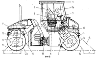
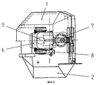
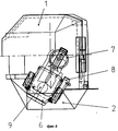
На фиг. 1 показан вид спереди дорожного катка с асимметрично расположенной кабиной; на фиг. 2 вид сбоку упомянутого дорожного катка; на фиг. 3 вид сверху интерьера кабины, когда сиденье для водителя расположено по центру при движении катка вперед; на фиг. 4 вид сверху интерьера кабины, когда сиденье водителя повернуто и смещено в горизонтальной плоскости, чтобы водитель имел отличный обзор за положением правых кромок вальцов через окно в асимметричной части кабины в процессе движения дорожного катка вперед. In FIG. 1 shows a front view of a road roller with an asymmetrically located cab; in FIG. 2 is a side view of said road roller; in FIG. 3 is a top view of the interior of the cabin when the driver's seat is centered when the roller moves forward; in FIG. 4 is a top view of the interior of the cab when the driver's seat is rotated and shifted in a horizontal plane so that the driver has an excellent view of the position of the right edges of the rollers through the window in the asymmetric part of the cab while the road roller is moving forward.
Дорожный каток содержит асимметричную безопасную кабину 1 с секцией 2 справа, по направлению движения, которая выходит за пределы внешней кромки 4а правого переднего вальца 4. В данном случае, левая часть 3 кабины не выходит за пределы внешней кромки вилкообразной детали левого вальца 5. Вращающееся с возможностью смещения в горизонтальной плоскости сиденье водителя 6 (сиденье водителя 6, рулевое колесо 7 и органы управления 8 имеют одну общую раму) показано в правильной позиции, которая дает водителю 9 отличный обзор вдоль кромки 4а вальца. Сиденье водителя также оборудовано предохранительным ремнем (не показан), а сама кабина имеет защиту против опрокидывания, т.е. кабина сконструирована и прикреплена к раме дорожного катка с таким расчетом, чтобы она защищала водителя в случае опрокидывания катка. Передний валец 4 катка жестко крепится к рамной секции 10 с помощью вилкообразной детали вальца 5. Задний конец 12 шарнирно крепится к рамной секции 11 с помощью вилкообразной детали вальца 13. Рамные секции 10 и 11 соединены между собой с помощью рулевого механизма рамы 18. Передняя рамная секция 10 оборудована асимметричной безопасной кабиной 1, в которой расположено вращающееся с возможностью смещения в горизонтальной плоскости сиденье водителя 6 вместе с выполненными за одно целое рулевым колесом 7 и органами управления 8. Линии обзора оператора 9 вдоль кромки переднего вальца обозначены ссылочными позициями 14 и 15, а видимая в процессе движения катка вперед за пределами кромки вальца площадь поверхности земли помечена буквой "х". При движении дорожного катка назад с помощью линий обзора 16 и 17 оператор может видеть за пределами кромки 12а вальца площадь поверхности земли, помеченную буквой "у". The road roller contains an asymmetric safety cabin 1 with a section 2 on the right, in the direction of movement, which extends beyond the outer edge 4a of the right front roller 4. In this case, the left part 3 of the cab does not extend beyond the outer edge of the fork-shaped part of the left roller 5. Rotating with the possibility of horizontal displacement of the driver’s seat 6 (driver’s seat 6, steering wheel 7 and controls 8 have one common frame) is shown in the correct position, which gives the driver 9 an excellent view along the edge 4a of the roller. The driver's seat is also equipped with a safety belt (not shown), and the cab itself has protection against tipping over, i.e. the cab is designed and attached to the frame of the road roller so that it protects the driver in case of rollover. The front roller 4 of the roller is rigidly attached to the frame section 10 using a fork-shaped part of the roller 5. The rear end 12 is pivotally attached to the frame section 11 using a fork-shaped part of the roller 13. The frame sections 10 and 11 are interconnected by the steering mechanism of the frame 18. Front frame section 10 is equipped with an asymmetric safety cabin 1, in which the driver’s seat 6, rotating with the possibility of horizontal displacement, is located together with the steering wheel 7 and controls 8 made in one piece. 9 along the edge of the front roller are designated by reference numerals 14 and 15, as visible in the process of movement of the roller along the outside edge of the roll surface area of the land is marked with the letter "x." When the road roller moves backward using the lines of sight 16 and 17, the operator can see the area of the earth marked with the letter “y” outside the edge of the roller 12a.