DETAILED DESCRIPTION OF THE INVENTION
FIELD OF THE INVENTION
-
The present invention relates to a man-driven vehicle
equipped with a capsule-like cover structure.
BACKGROUND OF THE INVENTION
RELATED ART
-
The man-driven vehicle equipped with a hood for weather
protection means is well known, for example, from Japanese
Laid-Open Patent Application Gazette No. 1999-59553 disclosing
a man-driven vehicle having a hood extending merely above a
driver or from Japanese Laid-Open Patent Application Gazette
No. 1975-41243 disclosing a man-driven vehicle having a hood
detachably provided so as to extend merely above a driver.
-
It is also well known to provide the vehicle's wheels with
splash board means.
PROBLEM TO BE SOLVED BY THE INVENTION
-
None of the man-driven vehicle having a cover structure
adapted for entirely covering the vehicle has been proposed.
With the conventional hood extending merely above the driver,
it is impossible to protect the driver against side blow of rain
and wind because the driver is laterally unguarded.
-
Even with the cover structure adapted to guard the driver
against side flow of rain and wind, it is impossible to protect
the driver against muddy water, dust, insects, rain, snow, chill,
hot air or the like because such cover structure of prior art
is opened downward.
-
It is often impossible for the mudguard alone to protect
the driver from mud and water splashed from rain puddle or the
like and if wind and rain are relatively fierce, the driver's
feet are often wet with rain and wind blowing up from beneath.
-
Furthermore, the cover structure adapted to cover the
driver from above has another inconvenience that the driver must
attach and detach such cover structure to the vehicle every time
the driver gets on and off the vehicle.
SUMMARY OF THE INVENTION
-
In view of the problem as has been described above, it
is a principal object of the invention to provide a man-driven
vehicle equipped with a cover structure adapted to cover
substantially whole of the vehicle which is, in turn, provided
with a selectively openable and closable door way through which
a driver can get on and off the vehicle, as described in Claim
1.
-
With this arrangement, the cover structure adapted to
cover substantially whole of the vehicle allows the vehicle to
run even under adverse environmental condition such as rainfall,
cold gale, sandblast or the other adverse weather and
environment. In fine weather, the openable and closable door
way of the cover structure may be operated to enjoy comfortable
landscape and to respire outer fresh air. Not only in doors but
also out of doors, it is possible to work pedals on the vehicle
in a stationary state for the purpose of health maintenance or
battery charging with the cover structure being opened. In
addition, the driver can easily get on or off the vehicle through
the opennable and closable door way.
-
The present invention provides also the man-driven
vehicle equipped with the cover structure wherein the cover
structure substantially covering whole of the vehicle is fixed
to a vehicle frame and the cover structure is provided with the
a door for getting on and off, as described in Claim 2.
-
With this arrangement, the cover structure covering
substantially whole of the vehicle is fixed to the vehicle frame
to protect the driver from wind, rainfall, UV (sunlight) or the
like and the cover structure is provided with the door to
facilitate the driver to get on and off the vehicle.
-
The present invention provides also the man-driven
vehicle equipped with the cover structure according to Claim
2 wherein said door is provided on one side or each side of said
cover structure, as described in Claim 3.
-
In this way, the door provided on one or both sides of
the cover structure facilitates the driver to get on and off
the vehicle.
-
The present invention provides also the man-driven
vehicle equipped with the cover structure according to Claim
2 or 3 wherein said door is adapted to be opened and closed in
slide mode, as described in Claim 4.
-
With this arrangement, the door slides along the cover
structure so that the door can be opened or closed even in a
restricted space without projecting sideways and a
correspondingly large door way can be ensured.
-
The present invention provides also the man-driven
vehicle equipped with the cover structure according to Claim
2 or 3 wherein said door is adapted to be opened and closed in
hinge mode.
-
With this arrangement, the door can be opened or closed
by means of a relatively simple hinge mechanism.
-
The present invention provides also the man-driven
vehicle equipped with the cover structure according to any one
of Claims 2 through 5 wherein said door is a combination of a
door section adapted to be opened in slide mode and a door section
adapted to be closed in hinge mode, as described in Claim 6.
-
Such combination of the door section of slide mode and
the door section of hinge mode is effective to reduce a slide
range of the door, to enlarge the door way and to enable the
door of hinge mode to be opened or closed even in a restricted
space.
-
The present invention provides also the man-driven
vehicle equipped with the cover structure according to Claim
6 wherein the door section adapted to be opened and closed in
hinge mode is connected to the door section adapted to be opened
and closed in slide mode by means of hinge members, as described
in Claim 7.
-
With this arrangement, the door of hinge mode may be opened
after the door of slide mode has been moved to the end of the
door way to complete opening of the door. In other words, the
door as a whole can be opened completely with a lateral extension
of the hinge mode door only by a width thereof.
-
The present invention provides also the man-driven
vehicle equipped with the cover structure according to Claim
7 wherein said door section adapted to be opened and closed in
slide mode is connected to guide roller members of the cover
structure by means of hinge members so that the door may be
retracted within the cover structure, as described in Claim 8.
-
With this arrangement, the slide door hinge-connected to
the slide member of the cover structure is pivoted around the
hinge members as the door is closed, so the door is retracted
within the cover structure and a width of the vehicle during
its running may be correspondingly reduced.
-
The present invention provides also the man-driven
vehicle equipped with the cover structure according to Claim
6 wherein said door section adapted to be opened and closed in
slide mode is connected to said door section adapted to opened
and closed in hinge mode so that the door may be folded, as
described in Claim 9.
-
With this arrangement, the door can be opened without
inconvenience that the opened door might extend outward from
the cover structure so far as the door is adapted to be folded
inward.
-
The present invention provides also the man-driven
vehicle equipped with the cover structure according to any one
of Claims 2 through 9 wherein said door is detachably provided,
as described in Claim 10.
-
With this arrangement, the driver can get on or off the
vehicle by detaching the door and, if desired, the vehicle can
be driven with the door detached from the cover structure.
-
The present invention provides also the man-driven
vehicle equippe openable equipped with the cover structure
according to Claim 1 wherein the openable and closable door way
comprises a detachable cover structure, as described in Claim
11.
-
With this arrangement, the openable and closable door way
can be defined by a detachable cover structure.
-
The present invention provides also the man-driven
vehicle equipped with the cover structure according to Claim
11 wherein the detachable cover structure is entirely or
partially detachable, as described in Claim 12.
-
With this arrangement, the cover structure covering
substantially whole of the vehicle can protect the driver from
wind, rainfall, UV (sunlight) or the like and the cover structure
can be detached as a whole or partially so as to facilitate the
driver to get on and off the vehicle. In fine weather, the
openable and closable door way of the cover structure may be
detached to respire outer air as fresh as possible or to enjoy
forest bathing. Not only in doors but also out of doors, it is
possible to work pedals on the vehicle in a stationary state
for the purpose of health maintenance or battery charging with
the cover structure being opened.
-
The present invention provides also the man-driven
vehicle equipped with the cover structure according to Claim
11 wherein a cover structure mounting frame is integrally
provided on the vehicle itself and the detachable cover
structure is detachably mounted on the cover structure mounting
frame, as described in Claim 13.
-
With is arrangement, the detachable cover structure may
be detached from the cover mounting frame integrally provided
on the vehicle to simiplify a mechanism for detachably mounting
the cover structure and to facilitate the detachably mounting
operation. In addition to such convenience, the cover mounting
frame serves to reinforce the vehicle body and serves also as
a bumper after the detachable cover structure has been detached.
-
The present invention provides also the man-driven
vehicle equipped with the cover structure according to Claim
13 wherein the cover structure mounting frame is provided with
rail members adapted to guide the detachable cover structure
slidably in longitudinal direction of the vehicle as described
in Claim 14.
-
With this arrangement, the detachable cover structure is
slidably opened along the rail member and facilitates the driver
to get on and off the vehicle.
-
The present invention provides also the man-driven
vehicle equipped with the cover structure according to Claim
14 wherein the detachable cover structure is detachable in the
vicinity of ends of the respective rail members, as described
in Claim 15.
-
With this arrangement, the detachable cover structure can
be easily mounted or detached in the vicinity of the end of the
rail member.
-
The present invention provides also the man-driven
vehicle equipped with the cover structure according to Claim
14 or 15 wherein the rail members mounted on the cover structure
mounting frame are slidably provided with compromise rail
members along which the detachable cover structure is slidable,
as described in Claim 16.
-
With this arrangement, a length of the rail member can
be reduced by a length of the compromise rail and a slide range
of the detachable cover structure can be enlarged by the length
of the compromise rail.
-
The present invention provides also the man-driven
vehicle equipped with the cover structure according to any one
of Claims 11 through 16 wherein the detachable cover structure
is located on a rear half of the vehicle itself, as described
in Claim 17.
-
With this arrangement, the front cover section ensures
the vehicle to be driven without any problem even after the
detachable cover structure has been detached.
-
The present invention provides also the man-driven
vehicle equipped with the cover structure according to Claim
1 wherein the openable and closable door way comprises the
rotatable cover, as described in Claim 18.
-
With this arrangement, the openable and closable door way
can be easily rotated as the rotatable cover adapted to be
rotated and thereby to be opened.
-
The present invention provides also the man-driven
vehicle equipped with the cover structure according to Claim
18 wherein the cover structure covering substantially a whole
of the vehicle includes a ceiling adapted to be opened and closed
as the rotatable cover, as described in Claim 19.
-
With this arrangement, the cover structure adapted to
cover substantially whole of the vehicle allows the vehicle to
run even under adverse environmental condition such as rainfall,
cold gale, sandblast or the other adverse weather and
environment. In fine weather, the ceiling of the cover structure
may be opened to enjoy comfortable landscape and to respire and
touch outer fresh air. In doors, it is possible to work pedals
on the vehicle in a stationary state for the purpose of health
maintenance or battery charging with the ceiling being opened.
-
The present invention provides also the man-driven
vehicle equipped with the cover structure according to Claim
19 wherein the cover structure is integrally mounted on the
vehicle itself and the rotatable cover is rotatable relatively
to the cover structure, as described in Claim 20.
-
With this arrangement, the rotatable cover rotatably
mounted on the stationary cover structure integral with the
vehicle itself facilitates the rotatable cover to be made
integrally with the stationary cover structure and thereby
facilitates operation of assembly.
-
The present invention provides also the man-driven
vehicle equipped with the cover structure according to Claim
19 or 20, wherein the rotatable cover is rotatably mounted on
a rear half of the vehicle itself, as described in Claim 21.
-
With this arrangement, the front cover section ensures
the vehicle to run without any problem even after the rotatable
cover has been opened.
-
The present invention provides also the man-driven
vehicle equipped with the cover structure according to any one
of Claims 19 through 21, wherein the rotatable cover is mounted
on the cover structure so that the rotatable cover can slide
in longitudinal direction of the vehicle, as described in Claim
22.
-
With this arrangement, the rotatable cover may be
slidably moved rearward to adjust a size of opening on the side
of the vehicle and thereby to facilitate the driver to get on
or off the vehicle.
-
The present invention provides also the man-driven
vehicle equipped with the cover structure according to Claim
22, wherein the rotatable cover is adapted to be
positioning-stopped in the vicinity of the ends of the slide
members, as described in Claim 23.
-
With this arrangement, the rotatable cover can be
positioning-stopped in the vicinity of the end of the slide
member whether the rotatable cover is held opened or closed.
-
The present invention provides also the man-driven
vehicle equipped with the cover structure according to any one
of Claims 18 through 23, wherein the rotatable cover is
detachable, as described in Claim 24.
-
With this arrangement, in fine weather, the rotatable
cover may be detached to enjoy outer landscape or to respire
and touch fresh outer air. When the pedals are worked with the
vehicle held stationary indoors for the purpose of health
maintenance or battery charging, the rotatable cover can be
detached.
-
The present invention provides also the man-driven
vehicle equipped with the cover structure according to Claim
1, wherein the openable and closable door way comprises the
rotatable cover integrally mounted on the slide cover structure,
as described in Claim 25.
-
With this arrangement, depending on weather, ambient
temperature and landscape or the other environmental condition,
the rotatable cover may be adjustably opened or closed during
running to regulate the environmental condition within the
cover structure. In addition, the slide cover section may be
moved not only to enlarge an opened area of the rotatable cover
particularly for the pedal working for health maintenance or
various repairing works but also to facilitate the driver to
get one or off through the opened area of the rotatable cover.
-
The present invention provides the man-driven vehicle
equipped with the cover structure according to Claim 25, wherein
the slide cover structure is provided on the rear half of a
stationary cover structure, as described in Claim 26.
-
With this arrangement, the slide cover section lying on
the rear part of the stationary cover may be slidably moved to
enable the rotatable cover as well as the slide cover section
to be opened or closed without any problem in driving of the
vehicle
-
The present invention provides also the man-driven
vehicle equipped with the cover structure according to Claim
25 or 26, wherein one of the slide cover structure and the
stationary cover structure is provided with slide rails and the
other is provided with guide rollers adapted to slide along
these guide rails, as described in Claim 27.
-
With this arrangement, a simple construction comprising
the slide rails cooperating with the guide rollers ensures a
smooth sliding of the slide cover section relative to the
stationary cover and it is also possible to stop the slide cover
section at a desired position by providing the guide rollers
with braking means.
-
The present invention provides also the man-driven
vehicle equipped with the cover structure according to Claim
27, wherein the slide rails are provided on ends thereof with
stoppers, as described in Claim 28.
-
With this arrangement, the slide cover section can be
stopped at the slide terminating ends or at position along the
way by said stopper means.
-
The present invention provides also the man-driven
vehicle equipped with the cover structure according to any one
of Claims 25 through 28, wherein the slide cover structure is
detachably mounted on the stationary cover structure, as
described in Claim 29.
-
With this arrangement, after the slide cover section has
been detached from the stationary cover, not only the vehicle
can be uses without any problem but also the desired repairing
operation can be carried out.
-
The present invention provides also the man-driven
vehicle equipped with the cover structure according to any one
of Claims 27 through 29, wherein the slide rails are detachably
mounted on the guide rollers and the slide cover structure is
detachably mounted on the stationary cover structure, as
described in Claim 30.
-
With this arrangement, the slide rails can be easily and
reliably mounted on or detached from the guide rollers and
thereby the slide cover section can be easily and reliably
mounted on or detached from the stationary cover.
-
The present invention provides also the man-driven
vehicle equipped with the cover structure according to any one
of Claims 18 through 30, wherein said rotatable cover comprises
a plurality of rotatable cover sections, as described in Claim
31.
-
With this arrangement, a plurality of rotatable cover
sections facilitate a rotation angle as well as an opened area
of the rotatable cover to be adjusted and these sections may
be overlapped one upon another to enlarge the opened area.
-
The present invention provides also the man-driven
vehicle equipped with the cover structure according to Claim
31, wherein said rotatable cover comprises an upper rotatable
cover section, an intermediate rotatable cover section
overlapping said upper rotatable cover section, and a lower
rotatable cover section overlapping said intermediate
rotatable cover section, as described in Claim 32.
-
With this arrangement, the rotatable cover comprises
upper, intermediate and lower sections adapted to be overlapped
one upon another and to be fanned out.
-
The present invention provides also the man-driven
vehicle equipped with the cover structure according to Claim
31 or 32, wherein said cover structure has a shaft by which said
upper rotatable cover section, intermediate rotatable cover
section and lower rotatable cover section are rotatably
supported, as described in Claim 33.
-
With this arrangement, the rotatable cover can be
adjustably rotated around the axis thereof.
-
The present invention provides also the man-driven
vehicle equipped with the cover structure according to any one
of Claims 31 through 33, wherein said cover structure is
provided on its rear part with a receiving space for said
rotatable cover, as described in Claim 34.
-
With this arrangement, the rotatable cover can be stored
into a relatively small space provided on the rear part of the
stationary cover as the rotatable cover is opened.
-
The present invention provides also the man-driven
vehicle equipped with the cover structure according to any one
of Claims 31 through 34, wherein said plurality of rotatable
cover sections are operatively associated one with another by
means of interlocking means, as described in Claim 35.
-
With this arrangement, a plurality of rotatable cover
sections can controlled at a single position to be opened or
closed by using interlocking means.
-
The present invention provides also the man-driven
vehicle equipped with the cover structure according to Claim
35, wherein said interlocking means primarily comprise an
interlocking projection extending from one end of said upper
rotatable cover section as viewed in its opening and closing
direction so as to be in contact with said intermediate
rotatable cover section, an interlocking projection extending
from one end of said intermediate rotatable cover section as
viewed in its opening and closing direction so as to be in contact
with said upper rotatable cover section, an interlocking
projection extending from one end of said intermediate
rotatable cover section as viewed in its opening and closing
direction so as to be in contact with said said lower rotatable
cover section and an interlocking projection extending from one
end of said lower rotatable cover section as viewed in its
opening and closing direction so as to be contact with said
intermediate rotatable cover section, as described in Claim 36.
-
With this arrangement, the upper rotatable cover section
may be held by the hand and fanned out to fan out successively
the intermediate cover section and the lower rotatable cover
section. Similarly, the upper rotatable cover section may be
held by the hand and fan-folded to fanfold successively the
intermediate cover section and the lower rotatable cover
section.
-
The present invention provides also the man-driven
vehicle equipped with the cover structure according to any one
of Claims 31 through 36, wherein said interlocking projections
are provided with packing members, as described in Claim 37.
-
With this arrangement, the packing members provided on
the respective interlocking projections improve sealing
performance of respective joints, buffer collision among the
interlocking projections occurring when the respective
rotatable cover sections are interlocked one with another, and
stop the rotatable cover sections at desired opened positions
by a frictional resistance when the packing members between
respective pairs of the adjacent rotatable cover sections.
-
The present invention provides also the man-driven
vehicle equipped with the cover structure according to any one
of Claims 1 through 37, wherein the cover structure is provided
along its bottom with a ground contacting skirt, as described
in Claim 38.
-
With this arrangement, the cover structure practically
covering a whole of the vehicle well protects the driver from
adverse environmental conditions such as rain, wind and
UV (sunlight) and the flexible ground contacting skirt provided
along the bottom of the cover structure protects the driver from
muddy water, sandblast, insects, rain, wind, snow, chill and
warmth which otherwise would enter the cover structure from
below the driver's feet. The ground contacting skirt is
sufficient flexible to ensure the vehicle running without any
problem even when the skirt contacts the ground.
-
The present invention provides also the man-driven
vehicle equipped with the cover structure according to Claim
38, wherein said ground contacting skirt extends along the
entire bottom of the cover structure, as described in Claim 39.
-
With this arrangement, the ground contacting skirt
extends along the entire bottom of the cover structure and
reliably protects the driver against muddy water, sandblast,
insects, rain, wind, snow, chill and warmth which otherwise
would attach the driver's feet from every direction.
-
The present invention provides the man-driven vehicle
equipped with the cover structure according to Claim 38 or 39,
wherein said ground contacting skirt has at least one split
lying at its rear portion as viewed in the vehicle's running
direction so that the skirt splits off as the skirt contacts
any obstacle or the like, as described in Claim 40.
-
With this arrangement, even when the ground contacting
skirt comes in contact with any obstacle, the skirt splits off
along its split lying at its rear portion as viewed in the
vehicle's running direction so that the vehicle can pass such
obstacle and avoid any accident such as upset due to sudden
braking.
-
The present invention provides also the man-driven
vehicle equipped with the cover structure according to Claim
40, wherein said ground contacting skirt comprises a set of
bottom sections adapted to split off one from another, as
described in Claim 41.
-
With this arrangement, even if the ground contacting
skirt comes in contact with any obstacle during running, the
set of bottom sections are adapted to split off one from another
and sufficiently flexible to pass such obstacle and to ensure
the vehicle to continue to run.
-
The present invention provides also the man-driven
vehicle equipped with the cover structure according to Claim
41, wherein another set of bottom sections are provided so as
to cover the splits of the previously described set of bottom
sections, as described in Claim 42.
-
With this arrangement, said another set of bottom
sections cover the splits of the adj acent set of bottom sections
so as to protect the driver from muddy water, sandblast, insects,
wind, rain, snow, chill and warmth which otherwise would attack
the driver from below his or her feet.
-
The present invention provides also the man-driven
vehicle equipped with the cover structure according to Claim
42, wherein said two sets of bottom sections cooperate on with
another to form the overlapping bottom sections, as described
in Claim 43.
-
With this arrangement, the adjacent two sets of bottom
sections overlap one another and mutually cover the splits of
these two sets of bottom sections.
-
The present invention provides also the man-driven
vehicle equipped with the cover structure according to any one
of Claims 38 through 43, wherein said ground contacting skirt
is detachably mounted on the bottom of the cover structure, as
described in Claim 44.
-
With this arrangement, the ground contacting skirt can
be detachably attached to the bottom of the cover structure.
-
The present invention provides also the man-driven
vehicle equipped with the cover structure according to any one
of Claims 41 through 43, wherein said plurality of bottom
sections are detachably mounted one by one on the bottom of the
cover structure, as described in Claim 45.
-
With this arrangement, the bottom sections can be
detachably attached one by one to the bottom of the cover
structure.
-
The present invention provides also the man-driven
vehicle equipped with the cover structure according to any one
of Claims 38 through 45, wherein said ground contacting skirt
comprises elastically deformable member made of synthetic
rubber or synthetic resin, as described in Claim 46.
-
With this arrangement, the ground contacting skirt made
of elastically deformable material such as synthetic rubber or
synthetic resin is readily deformed even if the skirt comes in
contact with any obstacle so as to pass such obstacle and can
be detachably mounted on the cover structure without any loss
of its elastic deformability.
-
The present invention provides also the man-driven
vehicle equipped with the cover structure according to any one
of Claims 1 through 46, wherein the vehicle body is provided
with a floor panel, as described in Claim 47.
-
With this arrangement, the floor panel mounted on the
vehicle body effectively protect the driver against muddy water,
wind and rain which otherwise would attack the driver from below
his or her feet.
-
The present invention provides also the man-driven
vehicle equipped with the cover structure and the floor panel
according to Claim 47, wherein the floor panel is provided with
openings for feet setting on the ground, as described in Claim
48.
-
With this arrangement, the driver can set his or her feet
on the ground through the openings provided in the floor panel
for this purpose and thereby controllably brake, support or move
the vehicle without rising from the seat.
-
The present invention provides also the man-driven
vehicle equipped with the cover structure and the floor panel
according to Claim 48, wherein the openings for feet setting
on the ground are provided with an openable and closable floor
panel section, as described in Claim 49.
-
With this arrangement, the openings for feet setting on
the ground can be covered or uncovered, if necessary, by
operating the openable and closable floor panel section to block
adverse weather or to control the vehicle with the driver's feet
set on the ground.
-
The present invention provides also the man-driven
vehicle equipped with the cover structure and the floor panel
according to Claim 49, wherein the openable and closable panel
section comprise a slidable floor panel section, as described
in Claim 50.
-
With this arrangement, the floor panel section may be slid
to uncover the openings for feet setting on the ground.
-
The present invention provides also the man-driven
vehicle equipped with the cover structure and the floor panel
according to Claim 49, wherein the openable and closable floor
panel section comprises a hinged floor panel section, as
described in Claim 51.
-
With this arrangement, the openable and closable floor
panel section may be trampled down to open this floor panel
section in hinge mode until the free end of this floor panel
section comes in contact with the ground and thereby to control
the vehicle by the free end so as to be braked or supported.
-
The present invention provides also the man-driven
vehicle equipped with the cover structure and the floor panel
according to Claim 51, wherein the hinged floor panel section
having edges adapted to be in contact with the ground and to
brake the vehicle as the hinged floor panel section is opened,
as described in Claim 52.
-
With this arrangement,
-
The present invention provides also the man-driven
vehicle equipped with the cover structure and the floor panel
according to any one of Claims 47 through 52, wherein the floor
panel extends below the pedals, as described in Claim 53.
-
With this arrangement, the driver can work the foot pedals
above the floor panel and thereby reliably protect his or her
feet from adverse weather.
-
The present invention provides also the man-driven
vehicle equipped with the cover structure and the floor panel
according to any one of Claims 47 through 53, wherein an upright
splash board is provided on front or rear part of the floor panel
in association with the front wheel or each of the rear wheels,
as described in Claim 54.
-
With this arrangement, the upright portion rising from
the floor panel serve as a splash board operatively associated
with the front wheel or the rear wheels.
-
The present invention provides also the man-driven
vehicle equipped with the cover structure and the floor panel
according to any one of Claims 47 through 54, wherein the cover
structure is provided integrally with the floor panel and
extends above the floor panel so as to cover substantially whole
of the driver, as described in Claim 55.
-
With this arrangement, the cover structure substantially
covering a whole of the vehicle and the driver allows the driver
to be protected from undesirable environmental conditions such
as rainfall, cold wind, sandblast and to drive the vehicle
without any problem.
-
The present invention provides also the man-driven
vehicle equipped with the cover structure according to any one
of Claims 1 through 55, wherein the cover structure is provided
with a solar battery, as described in Claim 56.
-
With this arrangement, the solar cell provided on the
ceiling of the cover structure generates electricity used to
energize various lights or to charge an accumulator.
-
The present invention provides also the man-driven
vehicle equipped with the cover structure according to any one
of Claims 1 through 56, wherein the cover structure is provided
with a front light so that the vehicle can be driven in the night,
as described in Claim 57.
-
The present invention provides also the man-driven
vehicle equipped with the cover structure according to any one
of Claims 1 through 57, wherein the front window of the cover
structure is provided with a wiper so that the vehicle can be
driven in the rain, as described in Claim 58.
-
The present invention provides also the man-driven
vehicle equipped with the cover structure according to any one
of Claims 1 through 58, wherein the cover structure is provided
on its rear side with a tail light so that the other vehicles
approaching from behind can perceive the present of the vehicle,
as described in Claim 59.
-
The present invention provides also the man-driven
vehicle equipped with the cover structure according to any one
of Claims 1 through 59, wherein the vehicle itself has three
or more wheels, as described in Claim 60.
-
With this arrangement, the vehicle can stably run without
any anxiety that the vehicle might upset so far as the vehicle
has three or more wheels.
-
The present invention provides also the man-driven
vehicle equipped with the cover structure according to any one
of Claims 1 through 60, wherein the vehicle itself or the
detachable cover structure or the cover structure mounting
frame is provided with a battery adapted to be charged as the
vehicle runs, as described in Claim 61.
-
With this arrangement, the accumulator can be charged as
the vehicle runs and such accumulator can be selectively mounted
on the vehicle itself, the detachable cover or the cover
mounting frame.
-
The present invention provides also the man-driven
vehicle equipped with the cover structure according to any one
of Claims 1 through 61, wherein the vehicle itself or the cover
structure or the cover structure mounting frame is provided with
a stationary stand adapted for rotatably supporting the wheels
which are rotated as the pedals are worked, as described in Claim
62.
-
With this arrangement, keeping the vehicle in stationary
state, for example, indoors, the wheels supported by the
stationary stand may be rotated by foot pedal working for health
maintenance. The stationary stand may be mounted on the vehicle
itself, the cover structure or the cover mounting frame.
-
The present invention provides also the man-driven
vehicle equipped with the cover structure according to any one
of Claims 1 through 62, wherein the cover structure is provided
with openable and closable windows for repairing of the vehicle,
as described in Claim 63.
-
With this arrangement, the openable and closable windows
provided on the cover structure may be opened when it is desired
to repair the vehicle.
BRIEF DESCRIPTION OF THE DRAWINGS
-
- Fig. 1 is a simplified side view showing a first embodiment
of the man-driven vehicle equipped with a capsule-like cover
structure according to the present invention.
- Fig. 2 is a simplified front view showing the first
embodiment.
- Fig. 3 is a simplified plan view showing the first
embodiment.
- Fig. 4 is a simplified rear view showing the first
embodiment.
- Fig. 5 is a simplified bottom view showing the first
embodiment.
- Fig. 6 is a simplified exploded perspective view showing
important parts of the first embodiment.
- Fig. 7 is a simplified sectional view showing these
important parts.
- Fig. 8 is a simplified side view showing a second
embodiment.
- Fig. 9 is a simplified side view showing a third
embodiment.
- Fig. 10 is a simplified side view showing a fourth another
embodiment.
- Fig. 11 is a simplified perspective view showing
important parts of the fourth embodiment.
- Fig. 12 is a simplified side view showing a fifth
embodiment.
- Fig. 13 is a diagram schematically illustrating important
parts of the fifth embodiment.
- Fig. 14 is a scale-enlarged diagram schematically
illustrating the important parts of the fifth embodiment.
- Fig. 15 is a diagram schematically illustrating a manner
in which the important parts of the fifth embodiment operate.
- Fig. 16 is a diagram schematically illustrating another
manner in which the important parts of the fifth embodiment
operate.
- Fig. 17 is a simplified diagram illustrating important
parts of a sixth embodiment.
- Fig. 18 is a diagram schematically illustrating a manner
in which the important parts of the sixth embodiment operate.
- Fig. 19 is a diagram schematically illustrating another
manner in which the important parts of the sixth embodiment
operate.
- Fig. 20 is a front view showing the important parts of
the sixth embodiment.
- Fig. 21 is a plan view showing the important parts of the
sixth embodiment.
- Fig. 22 is a simplified side view showing a seventh
embodiment.
- Fig. 23 is a diagram schematically illustrating a manner
in which the seventh embodiment operates.
- Fig. 24 is a simplified front view showing important parts
of the seventh embodiment.
- Fig. 25 is a scale-enlarged sectional view showing the
important parts of the seventh embodiment.
- Fig. 26 is a diagram schematically illustrating the
important parts of the seventh embodiment.
- Fig. 27 is a simplified side view showing an eighth
embodiment.
- Fig. 28 is a simplified front view showing the eighth
embodiment.
- Fig. 29 is a simplified plan view showing the eighth
embodiment.
- Fig. 30 is a simplified rear view showing the eighth
embodiment.
- Fig. 31 is a simplified bottom view showing the eighth
embodiment.
- Fig. 32 is a simplified sectional diagram illustrating
important parts of the eighth embodiment.
- Fig. 33 is a simplified sectional diagram illustrating
the important parts of the eighth embodiment.
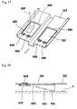
- Fig. 34 is a simplified perspective view showing a ninth
embodiment.
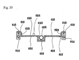
- Fig. 35 is a sectional view of the important parts as taken
along a line transversely extending in the longitudinal middle
of the vehicle according to the ninth embodiment.
- Fig. 36 is a simplified exploded view showing the
important parts of the ninth embodiment.
- Fig. 37 is a diagram schematically illustrating a manner
in which important parts of a tenth embodiment operate.
- Fig. 38 is a diagram schematically illustrating another
manner in which the important parts of the tenth embodiment
operate.
-
DESCRIPTION OF THE PREFRRED EMBODIMENTS
-
The embodiment of the man-driven vehicle equipped with
the capsule-like cover structure according to the present
invention as shown in Figs. 1 through 5 comprises a man-driven
vehicle itself 1, a cover structure 2 fixed to a frame 10 of
the vehicle itself 1 so as to cover a substantially entire
vehicle 1 and a door 6 mounted on said cover structure 2 for
getting on and off.
-
In the case of this embodiment, the cover structure 2
comprises a framed work made of transparent, translucent or
opaque synthetic resin sheet or the like. If the structure is
made of relatively flexible synthetic resin sheet or the like,
the cover structure 2 is reinforced by frame members (not shown)
and integrally fixed to a frame 10 of the vehicle itself 1 by
means of fastener members 4, 5 integrally mounted on the
framework or frame members.
-
In the case of the cover structure 2 made of reinforced
plastics or the like, the cover structure 2 holds its shape
without aid of any reinforcing means and may be directly fixed
to the vehicle itself 1. Compared thereto, if the cover
structure 2 is made of flexible synthetic resin sheet or the
like, the cover structure 2 may hold its shape with aid of the
frame members and integrally fixed to the frame 10 of the vehicle
itself 1 by means of the fastener members 4, 5 integrally mounted
on the framed work.
-
The cover structure 2 may be provided with absorption
ability for radiations such as UV ray to shield the radiations
such as UV ray known to be harmful to human body.
-
In the embodiment shown by Figs. 1 through 5, the door
6 really comprises a combination of a slide door section 6a and
a hinged door section 6b to be operated in association with each
other when the door 6 is opened and closed. Referring to Fig.
1, these slide door section 6a and hinged door section 6b are
connected by hinges 9 so that the slide door section 6a is
provided on its top and bottom with guide roller members 11,
12 adapted to roll on upper and lower slide members 7, 8 to open
the slide door section 6a and simultaneously the hinged door
section 6b may be opened to enlarge an opened width of the door
6 with a relatively limited extension of sliding.
-
In this manner, combination of the slide door with the
hinged door advantageously limits a sliding extension of the
door 6 in comparison with the case in which the door comprises
the slide door alone. Consequently, it can be avoided that the
slide members 7, 8 might excessively extend rearward. In
addition, it can be ensured that a lateral extension of the
hinged door section 6b from the cover structure 1 is
appropriately short as the hinged door section 6b is opened.
Thus the door 6 can be opened even in a restricted space.
Reference numeral 13 designates a doorknob and reference
numeral 13b designates a doorknob provided on the inner side
of the door.
-
Referring to Figs. 6 and 7, the door 6 is connected to
the upper and lower guide roller members 11, 12 by means of hinge
members 14 so that the door 6 may be entirely retracted within
a body frame 10a as the door 6 is closed, as indicated by dashed
lines in Fig. 7, and may be held in this retracted position during
running of the vehicle. Particularly referring to Fig. 7, the
hinge members 14 are pivotally connected to the respective guide
roller members 11, 12 around pivot pins 15 and pivotally
connected to respective door frames 16, 17 around respective
pivot pins 18 so that the door 6 is received in its closed, i.e.,
retracted position as the hinge members 14 are rotated
substantially by 90°.
-
In Figs. 6 and 7, reference numeral 19 designates guide
rollers constituting parts of the respective guide roller
members 11, 12.
-
Referring to Figs. 1 through 5, the door 6 is provided
with a pair of windows 20, 21 wherein the window 20 associated
with the slide door section 6a is opened and closed in slide
mode.
-
The door of hinge-slide combination type may be realized
also by a pair of doors hinge-connected to each other so that
the one door section is pivotally mounted on one side of the
door way to be opened or closed and the other door section is
opened or closed with its free end sliding along upper or lower
end of the door way. In this case, the door is preferably
constructed so as to be folded inward of the cover structure
2 and not to project outward of the cover structure 2 when the
door is opened or closed.
-
In the case of another embodiment shown by Fig. 8, the
door 6 is provided on the lateral side of the cover structure
2 so that the door 6 may be opened or closed in slide mode. The
cover structure 2 is provided with the upper and lower slide
members 7, 8 along which the door 6 is opened or closed in slide
mode. Optionally, the door 6 may be provided on one side or each
side of the cover structure 2.
-
According to this embodiment, the door 6 is adapted to
be opened or closed in slide mode in longitudinal direction of
the vehicle and thereby to ensure that the driver 3 can get on
or off the vehicle through the door way even if there is no
adequate free space on both sides of the vehicle. In addition,
the door 6 does not project laterally and, in consequence, a
relatively large door way is ensured.
-
In the case of an embodiment shown by Fig. 9, the door
6 is pivotally opened and closed on the hinges 9.
-
Alternatively, it is possible in this embodiment to
obtain the desired hinge function without separately providing
any hinge members. Specifically, a region in the cover structure
2 to be folded may be provided with sufficient flexibility to
be easily folded as with aid of the hinge members.
-
It is also possible in the above-described embodiment to
provide a locking member such as magnet, hook-and-loop fastener
or the other fastener between the door 6 and the door way of
the cover structure 2 so that the door 6 can be releasably locked
to the cover structure 2 at the opened or closed position of
the door 6. The driver 3 can selectively lock or unlock the door
6 to get on or off the vehicle and can drive with the door 6
held open, if desired to take in fresh and cool wind, for example,
in heat weather of summer.
-
Alternatively, the door 6 as a whole may be attached to
the door way of the cover structure 2 by releasable locking
member such as the magnet, the hook-and-loop fastener or the
other fastener so that the driver 3 can completely detach or
attach from and to the cover structure 2 to get on or off the
vehicle and, if desired, to remove the door 6.
-
In the case of the embodiment shown by Figs. 1 through
5, the front of the cover structure 2 is provided with a front
window 22, which is, in turn, provided with a wiper 23, and with
head lights 24 used in night so as to be visible from the sides
also. The cover structure 2 is provided on its rear side with
a sufficiently wide tail light 25 having a reflecting function
to be visible from the sides also. The tail light 25 can be used
also as a brake lamp.
-
Referring again to Fig. 1, reference numerals 28, 29
designate openable and closable windows provided at appropriate
regions of the cover structure for repair of the vehicle so that
these windows may be opened to repair vehicle's parts such as
tire and chain.
-
It is possible to provide on a ceiling 30 with solar cell
integrally with the ceiling 30 so that a battery equipped in
the vehicle may be charged during daylight and the various
lights such as the head light of the vehicle may be energized
during running at night.
-
The vehicle itself 1 can be equipped with the cover
structure 2 no matter whether the vehicle is two-wheeled,
three-wheeled or four-wheeled vehicle so far as the vehicle
itself 1 has an appropriate framework. However, the vehicle 1
preferably has three or more wheels in order to avoid an
apprehension that cross wind against the cover structure 2 might
upset the vehicle 1.
-
In Figs. 1 through 5, reference numeral 26 designates a
front wheel and reference numeral 27 designates a rear wheel.
-
Now the man-driven vehicle equipped with the cover
structure according to an embodiment shown by Figs. 10 and 11
will be described, in which an openable and closable door way
comprises a detachable cover structure.
-
Referring to Fig. 10, reference numeral 110 designates
a cover structure substantially covering whole of a vehicle
itself 101 wherein a front half of the cover structure 110 is
integral with the vehicle itself 101 in the form of a stationary
cover structure 111 and a rear half is in the form of a detachable
cover structure 112.
-
Along joint edges, the stationary cover structure 111 and
the detachable cover structure 112 may have U-shaped
cross-section and T-shaped cross-section, respectively,
adapted to be water-tightly engaged with each other or may
water-tightly overlap each other, both against weather. It is
possible to provide in the vicinity of the joint with an
operating knob to open or close the cover structure 110.
-
In the case of this embodiment, the cover structure 110
is made of transparent, translucent or opaque synthetic resin
sheet or the like. The cover structure 110 made of relatively
flexible synthetic resin sheet or the like will be fixed to a
cover structure mounting frame 113 to reinforce the cover
structure 110. Then the cover structure 110 will be integrally
fixed to the vehicle itself 101 by the framework which is
integral with the vehicle itself 101.
-
The cover structure 110 made of reinforced plastics or
the like will hold its shape by itself and can be directly fixed
to the vehicle itself 101. The cover structure 110 made of
flexible synthetic resin sheet, on the other hand, will hold
its shape by a separately provided framework and integrally
fixed to the cover structure mounting frame 113 of the vehicle
itself 101 by means of the framework.
-
The cover structure 110 may be UV shielding material to
protect human body from harmful UV.
-
Reference numeral 114 designates mounting angle members
being integral with the cover structure mounting frame 113 used
to mount the front stationary cover structure 111 on the vehicle.
Though not shown, the stationary cover structure 11 is provided
on its both sides with angle members of shapes identical to those
of the mounting angle members 113 so that the respective
mounting angle members 113 may be placed upon the associated
angle members and fixed one to another by means of fixing means
115.
-
In the case of this embodiment, the vehicle itself 1 is
a tricycle having a front wheel 102 for steerage and a pair of
rear wheels 103 serving to support a saddle 104. The cover
structure mounting frame 113 is held by locking means 105
integrally mounted on the body frame 106 so as to extend in
parallel to both sides of the front wheel as well as the rear
wheels.
-
Longitudinally opposite ends of the cover mounting frame
113 describe U-shapes adapted to protect the front wheel 102
and the rear wheels 103 from front and behind, respectively,
and serve also as bumpers. The frame 113 is provided on both
sides of its rear part with rail members 120 adapted to guide
the detachable cover 112 in the longitudinal direction of the
vehicle.
-
According to this embodiment, each of the rail members
120 comprises, as best seen in Fig. 11, a stationary rail member
121 fixed to the lateral surface of the cover mounting frame
113 and having a C-shaped cross-section, a compromise rail
member 124 integrally having a first connector rail member 122
slidably engaged with the stationary rail 121 with a square
U-shaped cross-section and a second connector rail member 123
extending along outer side of the first connector rail member
122 with a C-shaped cross-section, a guide rail 125 slidably
engaged with the compromise rail 124 with a square U-shaped
cross-section, and a mounting angle 126 integrally fixed to the
guide rail 125 by means of set screws 127 or the like.
-
As shown in Fig. 10, angle members 116 integrally mounted
on the detachable cover 112 are fixed to the respective mounting
angles 126 by means of set screws 117 or the like. The guide
rail 125 is detached from the second connector rail member 123
of the compromise rail member 124 as the detachable cover 112
is pulled rearward and thus the detachable cover 112 can be
removed.
-
Alternatively; it is possible to provide a stopper
adapted to prevent the compromise rail member 124 from falling
off from the stationary rail member 121. It is also possible
to provide a stopper between the guide rail 125 and the second
connector rail member 123 of the compromise rail member 124 so
that the compromise rail member 124 can be removed together with
the guide rail 125 from the stationary rail member 121 and thus
the detachable cover 112 can be removed.
-
A further alternative arrangement is also possible such
that the compromise rail member 124 is eliminated and the guide
rail 125 is movably engaged directly with the stationary rail
member 121.
-
In this way, the detachable cover 112 having moved along
the rail member 120 to the end of the rail member 120 in the
vicinity of which the detachable cover 112 can be removed and
the guide rail 125 can be easily attached to the stationary rail
member 121.
-
Though not illustrated, the cover structure may be
provided with knobs, side windows, a front window, a rear window,
side mirrors, wipers, head lights for running in night and a
tail light having a reflecting function.
-
Reference numeral 107 designates foot pedals of which a
driving is transmitted by a chain 108 extending between
sprockets to an intermediate shaft, then transmitted to an axle
of the rear wheels 103 by a chain 118 extending between the
intermediate shaft and the axle of the rear wheels 103. The
intermediate shaft contains therein a driving motor and a
generator 109.
-
Reference numeral 119 designates a space for storage of
the battery or the like and connected by wiring (not shown) to
the battery, the driving motor and the generator 109.
-
It is possible to mount components such as the battery,
the electric circuit and the wiring on the cover mounting frame
113 and the stationary cover 112.
-
Though not illustrated, the vehicle itself 101, the body
frame 106, the detachable cover 112 or the cover mounting frame
113 may be provided with a stationary stand used to keep the
vehicle stationary while the wheels are rotated by pedal working.
Such stationary stand is useful when the wheels are rotated by
pedal working for health maintenance indoors with the vehicle
kept stationary. The stationary stand may be selectively
mounted on the vehicle itself, the detachable cover or the cover
mounting frame.
-
Referring now to Figs. 12 through 16, an embodiment of
the man-driven vehicle equipped with the cover structure will
be described, wherein the openable and closable door way is
defined by the rotatable cover.
-
Reference numeral 210 designates a cover structure
substantially covering a whole of a vehicle itself 201 wherein
a front part as well as a rear-lower part of the cover structure
210 form together a stationary cover 211 being integral with
the vehicle itself 201. A rear-upper part of the cover structure
210 defines a rotatable cover 212.
-
Except schematically illustrated a driver seat 202,
driving mechanism 203, 204, 205, 206, 207, and front and rear
wheels 208, 209, details of the vehicle itself 201 are not
illustrated. When a user U on the seat 202 drives a driving wheel
203 by means of the foot pedals, an intermediate wheel 205 is
rotated by means of a chain 204, then a driven wheel 207 is
rotated by means of a chain 206 and then the rear wheels 209
are driven.
-
In this embodiment, the vehicle itself 201 is a tricycle
having the front wheel 208 serving for steerage and a pair of
the rear wheels 209.
-
Reference numeral 213 designates a rear cover upon which
the rotatable cover 212 is placed when the latter is opened.
While the rear cover 213 may be integral with the stationary
cover 211, an alternative arrangement is also possible such that
the rear cover 213 can be removed together with the rotatable
cover 212 from the stationary cover 211.
-
The joints of the stationary cover 211, the rear cover
213 and the rotatable cover 212 may be weather-tightly sealed
in projection-recess engaging mode or in overlapping mode, and
there may be provided in the vicinity of these joints with
detachable devices or stationary knobs by which the rotatable
cover 212 is opened or closed.
-
In the case of this embodiment, the cover structure 210
is made of transparent, translucent or opaque synthetic resin
sheet or the like and when the cover structure 210 is made of
relatively flexible synthetic resin sheet or the like, the cover
structure 210 may be reinforced by attaching the cover structure
210 to the cover mounting frame which forms of the framework
of the structure and integrally mounted on the vehicle itself
201 by such frame work which is, in turn, integral with the
vehicle itself 201.
-
When the cover structure 210 is made of reinforced
plastics or the like, the cover structure 210 can hold its shape
by itself and can be fixed directly to the vehicle itself 201.
-
The cover structure 210 may be made of UV shielding
material to protect the driver from harmful UV.
-
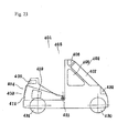
As best seen in Figs. 15 and 16, the rotatable cover 212
is rotatable around a rotary shaft 214 between an opened
position as shown in Fig. 15 and a closed position as shown in
Fig. 16. In fine weather, the rotatable cover 212 may be opened
to enjoy an outer landscape or to respire fresh air. When the
foot pedals are worked indoors for health maintenance or battery
charging with the vehicle kept stationary, the ceiling of the
cover structure may be opened. In adverse weather or environment,
the rotatable cover 212 may be closed so that the contact cover
structure 210 substantially covering a whole of the vehicle to
drive the vehicle without any problem.
-
The rotary shaft 214 is rotatably received in a
cylindrical bearing 215 and, in the embodiment shown by Figs.
12 through 14, the rotary shaft 214 has a D-shaped
cross-section.
-
A diameter-reduced slide bearing 216 extends rearward
from the cylindrical bearing 215 so that the rotary shaft 214
may slide into the slide bearing 216 as indicated by imaginary
lines in Fig. 14 as the rotary shaft 214 has been rotated together
with the rotatable cover 212 to its opened position. While the
rotatable cover 212 is set to be rotated together with the rotary
shaft 214 by about 60° in the case of the this embodiment, the
angle of rotation may be selectively set to 30° through 90° or
more.
-
According to this embodiment, an opened area of the
ceiling as well as of the both sides can be adjusted by sliding
the rotatable cover 212 in the longitudinal direction of the
vehicle as illustrated in Fig. 13. The rotatable cover 212 may
be slid rearward to facilitate the driver to get one or off the
vehicle
-
As best seen in Fig. 14, the slide bearing 216 lies at
a higher level than the cylindrical bearing 215 with the level
difference defined by a step 217. After has been rotated, the
rotatable cover 212 can not easily move to the slide bearing
216 so far as the rotary shaft 214 is lifted. In this manner,
the slide bearing 216 serves as a positioning stopper means.
-
Alternatively, a rear end 218 of the slide bearing 216
also may be provided with a recess serving to position and stop
the rotary shaft 214 via a step similar to the step 217.
-
Reference numeral 219 designates a circular operating
member adapted to rotate and to slide the rotatable cover 212
integrally with rotary shaft 214.
-
An arrangement is possible in which the rotatable cover
212 alone or integrally with the rear cover 213 can be removed.
With this arrangement, the rotatable cover may be removed in
fine weather to enjoy beautiful outer landscape and to respire
fresh air. When the foot pedals are worked indoors with the
vehicle kept stationary for health maintenance or battery
charging, the rotatable cover may be removed.
-
Furthermore, the cover structure 210 may be provided with
knobs, side windows 220, a front window 221, a ceiling window
222, a rear window 223, side mirrors, wipers, head lights 224
for running in night and tail lights 225 having a reflecting
function.
-
Though not illustrated, the driving wheel 203 driven by
the foot pedals, the intermediate wheel 205 or the driven wheel
207 is provided with the driving motor, the generator and the
battery adapted to be charged by foot pedal working.It is
possible to mount components such as the battery, the electric
circuit and the wiring on the cover mounting frame or the
stationary cover 211.
-
Though not illustrated, the vehicle itself 201, the body
frame, the stationary cover 211 or the cover mounting frame may
be provided with a stationary stand used to keep the vehicle
stationary while the wheels are rotated by pedal working. Such
stationary stand is useful when the wheels are rotated by pedal
working for health maintenance indoors with the vehicle kept
stationary. The stationary stand may be selectively mounted on
the vehicle itself, the rotatable cover or the cover mounting
frame.
-
Referring now to Figs. 17 through 21, an embodiment of
the man-driven vehicle equipped with the cover structure
substantially covering a whole of the vehicle is described, in
which the openable and closable door way is defined by the
rotatable cover integral with the slide cover.
-
Reference numeral 310 designates the cover structure
substantially covering a whole of a vehicle itself 301 wherein
a front part as well as a rear-lower part of the cover structure
310 form together a stationary cover 311 being integral with
the vehicle itself 301. A rear-upper part of the cover structure
310 defines a slide cover 313 adapted to slide rearward as
illustrated by Fig. 19.
-
A rotatable cover 312 is mounted on the slide cover 313
so as to be rotated integrally with a rotary shaft 314 and to
be rotated by an operating knob 319.
-
The rotary shaft 314 is rotatably received in a circular
rotary bearing 315 integrally fixed to the slide cover 313.
-
Except schematically illustrated a driver seat 302,
driving member 303, driven member 307, and front and rear wheels
308, 309, details of the vehicle itself 201 are not illustrated.
When a user U on the seat 302 drives a driving member 303 by
means of the foot pedals, a driven wheel 307 is rotated by means
of a chain or the like and then the rear wheels 309 are driven.
-
In this embodiment, the vehicle itself 301 is a tricycle
having a front wheel 308 for steerage and a pair of rear wheels
309.
-
The slide cover 313 is provided on its inner side, as shown
by Fig. 17 or 21, with slide rail members 316 extending in a
horizontal direction and the stationary cover 311 is provided
guide rollers 305, 306 adapted to guide the respective slide
rail members 316.
-
Reference numeral 317 designates stopper members
provided on ends of the respective slide rail members 316 and
adapted to come in contact with the respective guide rollers
305 at the slide limits. It is possible to provide supports for
the guide rollers 305, 306 or the stopper members with means
such as retractable or extensible/contractile means so that the
stopper members 317 can be moved beyond the guide rollers 305,
306 and thereby the slide cover 313 can be detached from or
attached to the stationary cover 311.
-
The joints of the stationary cover 311, the slide cover
313 and the rotatable cover 312 may be weather-tightly sealed
in projection-recess engaging mode or in overlapping mode, and
there may be provided in the vicinity of these joints with
detachable devices or stationary knobs by which the rotatable
cover 212 is opened or closed.
-
In the case of this embodiment, the cover structure 310
comprises a framed work made of transparent, translucent or
opaque synthetic resin sheet or the like. If the structure is
made of relatively flexible synthetic resin sheet or the like,
the cover structure 310 is reinforced by mounting the cover
structure 310 to the cover mounting frame for skeleton and
integral with the vehicle 301.
-
An arrangement is possible in which the rotatable cover
312 alone or integrally with the slide cover 313 can be removed.
With this arrangement, the slide cover may be removed in fine
weather to enjoy beautiful outer landscape and to respire fresh
air. When the foot pedals are worked indoors with the vehicle
kept stationary for health maintenance or battery charging, the
rotatable cover312 may be removed together with the slide cover.
-
Furthermore, the cover structure 310 may be provided with
knobs, side windows 320, a front window 321, a ceiling window
322, a rear window 323, side mirrors, wipers, head lights 324
for running in night and tail lights 325 having a reflecting
function.
-
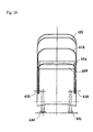
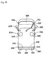
Referring now to Figs. 22 through 26, an embodiment of
the man-driven vehicle equipped with the cover structure
wherein an openable and closable door way comprises a plurality
of rotatable cover sections.
-
The man-driven vehicle 401 equipped with the cover
structure according to this embodiment comprises, as shown by
Fig. 22 or 23, a three- or four-wheel vehicle itself and a cover
structure 405 substantially covering a whole of the vehicle
itself. The cover structure 405 comprises a front part 402 of
the cover structure provided with windows 406, 407, 408, a rear
part 404 of the cover structure provided with a window 409 and
a rotatable cover 403 lying between these front and rear parts
and adapted to be funned out or fun-folded around a rotary shaft
415 for this cover.
-
According to this embodiment, the rotatable cover 403
comprises an upper rotatable cover section 411 having windows
410, an intermediate rotatable cover section 413 having windows
412 and adapted to overlap the inner side of the upper rotatable
cover section 411 and a lower rotatable cover section 413
adapted to overlap the inner side of the intermediate rotatable
cover section 414 so that the rotatable cover 403 is adapted
to be fun-folded toward the rear part 404 of the cover structure
around rotary shaft assembly 415.
-
As will be apparent from Fig. 25, the rotary shaft assembly
415 holds the rotatable cover 403 comprising the lower rotatable
cover section 414, the intermediate rotatable cover section 413
and the upper rotatable cover section 411 contacting one another
in this order from the inner side of the vehicle itself around
a rotary shaft 416 between an inner press plate 418 and an outer
press plate 471 and then fixed together by a set screw 419 so
as be supported in a central region of the cover structure 405.
-
The upper rotatable cover section 411, the intermediate
rotatable cover section 413 and the lower rotatable cover
section414 are provided, as best seen in Fig. 26, with
interlocking means, respectively, operating to fun out or fun-fold
the rotatable cover.
-
The interlocking means comprise interlocking projections
420, 421 extending downward from opposite ends of said upper
rotatable cover section 411 as viewed in its opening and closing
direction, an interlocking projection 422 extending upward from
one end of said intermediate rotatable cover 413 section as
viewed in its opening and closing direction, interlocking
projections 423, 424 extending from the other end of said
intermediate rotatable cover section 413 as viewed in its
opening and closing direction and an interlocking projection
425 extending upward from one end of said lower rotatable cover
section 414 as viewed in its opening and closing direction.
-
To fun-fold the rotatable cover 403, the upper rotatable
cover section 411 stored in the space 426 defined on the rear
part of the cover structure is held with the hand and rotated
forward whereupon the interlocking projection 421 of this
rotatable section comes in contact with the interlocking
projection 422 of the intermediate rotatable cover section 413
so as to force the intermediate rotatable cover section 413 to
be rotated forward. Thereupon, the interlocking projection 424
of the intermediate rotatable cover section 413 comes in contact
with the interlocking projection 425 of the lower rotatable
cover section 414 so as to force the lower rotatable cover
section 414 to be rotated forward. In this way, the rotatable
cover 403 is fun-folded with the upper rotatable cover section
411 being in contact integrally with the front part 402 of the
cover structure.
-
As illustrated by Fig. 26, the interlocking projections
422, 425 extending upward from the intermediate rotatable cover
section 413 and the lower rotatable cover section 414,
respectively, are provided on inner sides thereof with packing
members 427, 428 adapted to come in close contact with inner
surfaces of the upper rotatable cover section 411 and the
intermediate rotatable cover section 413, respectively. In this
way, the rotatable cover 403 is reliably locked in its
fun-folded position.
-
To fun out the rotatable cover 403, the upper rotatable
cover section 411 is held with the hand and rotated rearward
whereupon the interlocking projection 420 comes in contact with
the interlocking projection 422 so as to force the intermediate
rotatable cover section 413 to be funned out and then the
interlocking projection 423 comes in contact with the
interlocking projection 425 so as to force the lower rotatable
cover section 414 to be funned out.
-
In the course of such operation for fun-folding or funning
out, a frictional force generated between each pair of the
overlapping cover sections or a contact resistance of the
packing members 427, 428 allows the rotatable cover to be fixed
at a desired position.
-
Reference numeral 430 designates a front wheel of the
vehicle itself, reference numeral 431 designates a pair of rear
wheels and reference numeral 432 designates a head light.
-
Referring now to Figs. 27 through 33, an embodiment of
the man-driven vehicle equipped with the cover structure
wherein the cover structure is provided along its bottom with
a ground contacting skirt so that the driver can be protected
from muddy water, sandblast, insects, wind, rain, snow, chill
and warmth which otherwise would attach the driver from below
his or her feet.
-
According to this embodiment, a cover structure 502
substantially covering a whole of a vehicle itself 501 is fixed
to a frame 510 of the vehicle 501 and the cover structure 502
is provided with a door 506 through which the driver may get
on or off the vehicle 501.
-
In this embodiment, the flexible ground contacting skirt
530 provided along the bottom of the cover structure protects
the driver from muddy water, sandblast, insects, rain, wind,
snow, chill and warmth which otherwise would enter the cover
structure from below the driver's feet. The ground contacting
skirt 530 is sufficient flexible to ensure the vehicle running
without any problem even when the skirt contacts the ground.
-
The ground contacting skirt 530 extends along the entire
bottom of the cover structure and reliably protects the driver
against muddy water, sandblast, insects, rain, wind, snow,
chill and warmth which otherwise would attach the driver's feet
from every direction.
-
The ground contacting skirt 530 comprises comprises a
plurality of bottom sections 531 splitted one from another so
that, even when the ground contacting skirt 530 comes in contact
with any obstacle during running, these bottom sections 531 are
sufficiently flexible and the vehicle can pass such obstacle
and continue to run without any problem.
-
Based on this embodiment, the ground contacting skirt 530
can be arranged as illustrated by Fig. 32(1), in which another
set of bottom sections 541 is placed on the set of bottom section
531 so that each of the bottom sections 541 may cover a split
532 between each pair of the adjacent bottom sections 531. In
this way, it is possible to protect the driver from muddy water,
sandblast, insects, wind, rain, snow, chill and warmth which
otherwise would enter the vehicle through the splits 532 and
attach the driver.
-
It is also possible, as illustrated by Fig. 32 (2) or (3),
to arrange two sets of bottom sections 531, 541 so that these
two sets of bottom sections 531, 541 overlap one another and
mutually cover the splits 532, 542 of these two sets of bottom
sections.
-
An arrangement as illustrated by Fig. 33 is also possible,
in which there are provided two sets of bottom sections 541 with
the set of bottom sections 531 therebetween and doubly cover
the splits 532 of the set of bottom sections 531.
-
In the case of this embodiment, a part or a whole of the
ground contacting skirt 530 may be detachably attached to the
bottom of the cover structure 502 in the conventional manner
so that, if desired for example in fine weather, the skirt 530
can be removed.
-
Alternatively, the bottom sections 531 may be detachably
attached one by one to the bottom of the cover structure 502
in the conventional manner so that a damaged bottom section can
be exchanged with a new bottom section.
-
The ground contacting skirt 530 may be formed by the bottom
sections made of elastically deformable synthetic rubber sheet
or synthetic resin sheet to ensure that, even if the bottom
sections come in contact with any obstacle, the bottom sections
may readily be elastically deformed and pass such obstacle. It
is easy for the bottom sections made of such elastically
deformable material to be detachably attached to the cover
structure.
-
The ground contacting skirt 530 may be provided with at
least one split lying at its rear portion as viewed in the running
direction of the vehicle itself 501 instead of providing the
splits fully along the bottom of the cover structure 502 so that
the skirt splits off as the skirt contacts any obstacle and this
obstacle enters the inner side of the ground contacting skirt,
the skirt splits off along its split lying at its rear portion
as viewed in the vehicle's running direction so that the vehicle
can pass such obstacle and avoid any accident such as upset due
to sudden braking.
-
In the case of this embodiment, the cover structure 502
comprises a framed work made of transparent, translucent or
opaque synthetic resin sheet or the like. If the structure 502
is made of relatively flexible synthetic resin sheet or the like,
the cover structure 502 is reinforced by frame members (not
shown) and integrally fixed to a frame 10 of the vehicle itself
501 by means of fastener members 504, 505 integrally mounted
on the framework or frame members 510 of the vehicle itself 501.
-
In the case of the cover structure 502 made of reinforced
plastics or the like, the cover structure 502 holds its shape
without aid of any reinforcing means and may be directly fixed
to the vehicle itself 501. Compared thereto, if the cover
structure 502 is made of flexible synthetic resin sheet or the
like, the cover structure 502 may hold its shape with aid of
the frame members and integrally fixed to the frame 510 of the
vehicle itself 501 by means of the fastener members 504, 505
integrally mounted on the framed work 510 of the vehicle itself
501
-
Even when the cover structure 502 is transparent, the
cover structure may be provided with UV shielding property by
coating treatment or the like to protect human body from harmful
UV.
-
In the embodiment illustrated by Figs. 27 through 31, the
door 506 comprises a slide door 506a and a hinged door 506b.
Referring to Fig. 27, the slide door 506a is provided with hinge
members by means of which the slide door 506a is connected to
the hinged door 506b. The slide door 506a is provided on its
top and bottom with guide roller members 511, 512 by means of
which the slide door 506a slides rearward along slide members
507, 508 to be opened whereupon the hinged door 506b is opened.
In this way, the opening width of the door way can be enlarged
with a relatively restricted range of sliding.
-
In this manner, combination of the slide door 506a with
the hinged door 506b advantageously limits the range of sliding
extension of the door 506 in comparison with the case in which
the door comprises the slide door alone. Consequently, it can
be avoided that the slide members 507, 508 might excessively
extend rearward. In addition, it can be ensured that a lateral
extension of the hinged door 506b from the cover structure 501
is appropriately short as the hinged door 6b is opened. Thus
the door 506 can be opened even in a restricted space. Reference
numeral 513 designates a doorknob and a similar doorknob may
be provided also on the inner side of the door.
-
Referring to Figs. 27 through 31, the door 506 is provided
with a pair of windows 514, 515 wherein the window 515, 514
associated with the slide door 506a and the hinged door 506b
may be opened and closed in slide mode.
-
The door of hinge-slide combination type may be realized
also by a pair of doors hinge-connected to each other so that
the one door section is pivotally mounted on one side of the
door way to be opened or closed and the other door section is
opened or closed with its free end sliding along upper or lower
end of the door way. In this case, the door is preferably
constructed so as to be folded inward of the cover structure
502 and not to project outward of the cover structure 502 when
the door is opened or closed.
-
Alternatively, it is possible in this embodiment to
obtain the desired hinge function without separately providing
any hinge members. Specifically, a region in the cover structure
502 to be folded may be provided with sufficient flexibility
to be easily folded as with aid of the hinge members.
-
It is also possible in the above-described embodiment to
provide a locking member such as magnet, hook-and-loop fastener
or the other fastener between the door 506 and the door way of
the cover structure 502 so that the door 506 can be releasably
locked to the cover structure 502 at the opened or closed
position of the door 506. The driver 503 can selectively lock
or unlock the door 506 to get on or off the vehicle and can drive
with the door 506 held open, if desired to take in fresh and
cool wind, for example, in heat weather of summer.
-
Alternatively, the door 506 as a whole may be attached
to the door way of the cover structure 502 by releasable locking
member such as the magnet, the hook-and-loop fastener or the
other fastener so that the driver 503 can completely detach or
attach from and to the cover structure 502 to get on or off the
vehicle and, if desired, to remove the door 506.
-
It is possible to provide the doors 506 on lateral sides
of the cover structure 502 so that these doors 506 may be opened
or closed in slide mode.
-
In this case, the door 506 is adapted to be opened or closed
in slide mode in longitudinal direction of the vehicle and
thereby to ensure that the driver 503 can get on or off the
vehicle through the door way even if there is no adequate free
space on both sides of the vehicle. In addition, the door 506
does not project laterally and, in consequence, a relatively
large door way is ensured.
-
In the case of the embodiment shown by Figs. 27 through
31, the front of the cover structure 502 is provided with a front
window 509, which is, in turn, provided with a wiper 517, and
with head lights 518 used in night so as to be visible from the
sides also. The cover structure 502 is provided on its rear side
with a rear window 516 and a sufficiently wide tail light 519
to be visible from the sides also. The rail light 591 lies below
the rear window 516 and has a reflecting function. The tail light
25 can be used also as a brake lamp.
-
The vehicle itself 501 can be equipped with the cover
structure 502 no matter whether the vehicle is two-wheeled,
three-wheeled or four-wheeled vehicle so far as the vehicle
itself 1 has an appropriate framework. However, the vehicle
itself 501 has preferably three or more wheels in order to avoid
an apprehension that cross wind against the cover structure 502
might upset the vehicle itself 501.
-
Referring now to Figs. 34 through 38, an embodiment of
the man-driven vehicle equipped with the cover structure
according to the present invention will be described, in which
the cover structure is provided on its bottom with a floor panel
serving to protect the driver from muddy water, sandblast,
insects, wind, rain, snow, chill and warmth which otherwise
would attach the driver from below his or her feet.
-
Referring to Fig. 34, reference numeral 601 designates
a vehicle body comprising a center chassis 602 in form of thick
pipe. The center chassis 602 is provided at its front end with
a handle bearing 604 adapted for integrally and rotatably
supporting a handle 603, a front fork 605 and a front wheel 606
and at its rear part 607 with a pair of rear wheels 609 supported
via a bifurcated rear fork 608. A seat lies above the rear part
607 of the center chassis 602.
-
Reference numeral 611 designates a cover structure
adapted for substantially complete covering of the vehicle and
the driver. Reference numeral 612 designates foot pedals
functioning to drive a rotary shaft for the rear wheels 609 via
a chain (not shown).
-
Front and rear bottom chassis 613 and right and left bottom
chassis 614 integral with each other are fixed to the center
chassis 602 to mount a floor panel 610. The right and left bottom
chassis 614 are integrally provided with fixing brackets 615
on which a stationary floor panel 617 by set screws 616. As
illustrated by Fig. 35, the stationary floor panel 617 is formed
along its longitudinal center line with a crook 618 and includes
right and left stationary frame members 619.
-
The cover structure 611 is integrally mounted on the
bottom chassis 613, 614.
-
The stationary floor panel 617 is provided with openings
621 for feet setting on the ground and these openings 621 are
openably covered with openable and closable floor panel section
620.
-
In the embodiment illustrated by Figs. 34 through 36, the
openable and closable floor panel section 620 has a recess 622
extending along and being engaged with the crook 618 of the
center chassis 602 and rising frames 623 lying on both sides
of the recess 622 and brought in contact with the respective
stationary frames 619. As has been described with reference to
Fig. 1, the floor panel section 620 slides in a direction
indicated by an arrow to uncover the openings 621 so that the
driver may set his or her feet on the ground through these
openings 621 without standing up from the seat to control the
vehicle so as to be stopped or moved. The floor panel section
620 may be slid in the direction opposite to the arrow to cover
the openings 621 again and thereby to block muddy water, wind
or rain. Reference numeral 624 designates a projection used to
operate the floor panel section 620.
-
Finally, in the case of an embodiment illustrated by Figs
37 and 38, the openings 621 of the stationary floor panel 617
for feet setting on the ground are covered from below with an
opennable and closable floor panel section 630. When the driver
puts his or her feet 626 on this floor panel section 630, as
illustrated by Fig. 37, the floor panel section 630 rotates
around hinges 625 as indicated dashed lines in Fig. 37 until
an end 631 of the floor panel section 630 opposite to the hinges
625 comes in contact with the ground G so as to brake and to
stop the vehicle. The vehicle runs in the direction of the arrow,
i.e., leftward as viewed in Fig. 38.
-
The hinges 625 are loaded on lower sides thereof with leaf
springs 627 and the floor panel section 630 is normally closed.
When the driver tramples down the floor panel section 630
against the force of these leaf springs 627, the openings 621
are uncovered, and when the driver puts his or her feet off from
the floor panel section 630, the openings 621 are covered again.
-
Size, number and location of the opening 621 are not
limited to those as have been described above and may be
appropriately selected. It is possible to provide the openable
and closable floor panel sections associated with the
respective openings 621. It is also possible to interlock the
floor panel section 630 with the pair of openings 621 for feet
setting on the ground so that the pair of openings 621 may be
uncovered at once as the floor panel section 630 is trampled
down.