RU2025373C1 - Spare wheel carrier - Google Patents
Spare wheel carrier Download PDFInfo
- Publication number
- RU2025373C1 RU2025373C1 SU5030358A RU2025373C1 RU 2025373 C1 RU2025373 C1 RU 2025373C1 SU 5030358 A SU5030358 A SU 5030358A RU 2025373 C1 RU2025373 C1 RU 2025373C1
- Authority
- RU
- Russia
- Prior art keywords
- strut
- hinge
- vertical
- bracket
- shaped
- Prior art date
Links
- 239000000126 substance Substances 0.000 abstract 1
- 238000009434 installation Methods 0.000 description 1
- 230000008092 positive effect Effects 0.000 description 1
Images


Landscapes
- Fittings On The Vehicle Exterior For Carrying Loads, And Devices For Holding Or Mounting Articles (AREA)
Abstract
Description
Изобретение относится к транспортным средствам, в частности к специальному оборудованию транспортного средства. The invention relates to vehicles, in particular to special equipment of a vehicle.
Известно устройство для установки запасного колеса на транспортном средстве, имеющее промежуточный кронштейн, шарнирно связанный с поддерживающим рычагом, и винтовой механизм для перемещения промежуточного кронштейна, при этом поддерживающий рычаг снабжен фиксатором его положения относительно промежуточного кронштейна. A device for mounting a spare wheel on a vehicle is known, having an intermediate bracket pivotally connected to a supporting lever, and a screw mechanism for moving the intermediate bracket, while the supporting lever is provided with a lock of its position relative to the intermediate bracket.
Недостатком данного устройства являются сложность конструкции, ограниченная зона действия в горизонтальной плоскости, большая вероятность повреждения устройства при проведении погрузочно-разгрузочных работ. The disadvantage of this device is the design complexity, limited coverage in the horizontal plane, a high probability of damage to the device during loading and unloading.
Наиболее близким по технической сущности и достижению положительного эффекта к заявляемому является устройство для установки запасного колеса на низкорамное транспортное средство, которое снабжено шарнирно связанной нижним концом с неподвижным кронштейном вертикальной стойкой с буртиком, состоящей из двух частей, связанных между собой горизонтальным шарниром и механизмом для фиксации упомянутой стойки в вертикальном положении, а на верхнем ее конце с возможностью поворота в горизонтальной плоскости шарнирно закреплен откидной кронштейн. The closest in technical essence and the achievement of a positive effect to the claimed is a device for mounting a spare wheel on a low loader vehicle, which is equipped with a hinged lower end with a fixed bracket vertical strut with a shoulder, consisting of two parts connected by a horizontal hinge and a mechanism for fixing said strut in a vertical position, and at its upper end with the possibility of rotation in a horizontal plane, a hinged cut is pivotally fixed Nstein.
Недостатком данного устройства являются сложность конструкции механизма фиксации стойки и ограниченная зона действия устройства в горизонтальной плоскости. The disadvantage of this device is the design complexity of the rack fixing mechanism and the limited range of the device in the horizontal plane.
Указанная цель достигается тем, что в устройстве для установки запасного колеса на транспортном средстве, содержащем неподвижный кронштейн, смонтированный на транспортном средстве, вертикальную стойку, шарнирно связанную с неподвижным кронштейном посредством вертикальной оси и выполненную из верхней и нижней частей, соединенных между собой горизонтальным шарниром и фиксирующим элементом, и несущий запасное колесо откидной кронштейн, соединенный с верхней частью вертикальной стойки посредством шарнира и съемного стопора, выполненного в виде пальца с рукояткой на одном его конце, установленного в отверстиях кронштейна и стойки, согласно изобретению вертикальная стойка выполнена П-образной в поперечном сечении, фиксирующий элемент стойки выполнен в виде съемного пальцевидного стопора, образующего второй горизонтальный шарнир, а откидной кронштейн выполнен из двух шарнирно связанных между собой П-образных в поперечном сечении частей - стрелы и подкоса, первая из которых соединена посредством упомянутого съемного стопора с вертикальной стойкой на ее верхнем конце, а вторая соединена со стойкой посредством упомянутого шарнира, расположенного ниже стопора, причем второй конец последнего выполнен с пазом, в котором шарнирно установлен фиксатор, при этом стрела, подкос и верхняя часть вертикальной стойки в своих поперечных сечениях выполнены с возможностью их последовательного складывания друг в друга в транспортном нерабочем положении. This goal is achieved by the fact that in the device for installing a spare wheel on a vehicle containing a fixed bracket mounted on the vehicle, a vertical strut pivotally connected to the fixed bracket via a vertical axis and made of upper and lower parts interconnected by a horizontal hinge and a locking element, and a hinged bracket carrying a spare wheel, connected to the upper part of the vertical rack by means of a hinge and a removable stopper In the form of a finger with a handle at one end thereof installed in the holes of the bracket and the stand, according to the invention, the vertical stand is made U-shaped in cross section, the fixing element of the stand is made in the form of a removable finger-shaped stopper forming a second horizontal hinge, and the hinged bracket is made of two pivotally connected U-shaped in cross section parts - boom and strut, the first of which is connected by means of the said removable stopper with a vertical strut at its upper end, and the second is connected to the rack by means of the hinge located below the stopper, the second end of the latter being made with a groove in which the latch is pivotally mounted, while the arrow, strut and the upper part of the vertical rack in their cross sections are made with the possibility of their successive folding into each other transport inoperative position.
Указанные признаки в совокупности с известными в прототипе позволяют достичь упрощение конструкции устройства, расширение зоны его действия в горизонтальной плоскости. These signs in combination with the known in the prototype can achieve a simplification of the design of the device, the expansion of its coverage in the horizontal plane.
Таким образом, предложенное техническое решение удовлетворяет критерию "новизна". Thus, the proposed technical solution meets the criterion of "novelty."
Признаки, отличающие заявляемое техническое решение от прототипа, при сравнении с другими известными решениями не были выявлены, а это значит, что заявляемое техническое решение соответствует критерию "существенные отличия". Signs that distinguish the claimed technical solution from the prototype, when compared with other known solutions were not identified, which means that the claimed technical solution meets the criterion of "significant differences".
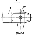
На фиг.1 изображено устройство для установки запасного колеса в рабочем положении, вид сбоку; на фиг.2 - вид по стрелке А на фиг.1; на фиг.3 - узел I на фиг.2; на фиг.4 - разрез Б-Б на фиг.1. Figure 1 shows a device for installing a spare wheel in the working position, side view; figure 2 is a view along arrow a in figure 1; figure 3 - node I in figure 2; figure 4 is a section bB in figure 1.
Устройство для установки запасного колеса содержит смонтированный на транспортном средстве неподвижный кронштейн 1, на котором посредством шарнира 2 установлена нижняя часть вертикальной стойки 3, а ее верхняя часть, выполненная П-образной в поперечном сечении, соединена с нижней частью посредством горизонтальных шарниров 4 и 5, при этом шарнир 5 является фиксирующим элементом стойки 3 и выполнен в виде пальцевидного стопора. Откидной кронштейн выполнен из двух шарнирно связанных между собой П-образных в поперечном сечении частей - стрелы 6 и подкоса 7, при этом стрела 6 соединена посредством съемного пальцевидного стопора 8 с вертикальной стойкой 3 на верхнем ее конце, а подкос 7 соединен со стойкой 3 посредством шарнира 9. Второй конец пальцевидных стопоров 5 и 8 выполнен с пазом, в который шарнирно установлен фиксатор 10. Стрела 6, подкос 7 и верхняя часть вертикальной стойки 3 в транспортном нерабочем положении последовательно складываются друг в друга, при этом стрела 6 с подкосом 7 фиксируются внутри верхней части вертикальной стойки 3 посредством стопора 8 в проушинах 11. The device for installing a spare wheel comprises a fixed bracket 1 mounted on the vehicle, on which the lower part of the
В транспортном положении устройство для установки запасного колеса занимает мало места и может быть расположено на транспортном средстве, исходя из необходимости, как вдоль, так и поперек транспортного средства. In the transport position, the device for installing the spare wheel takes up little space and can be located on the vehicle, based on the need, both along and across the vehicle.
Для приведения в рабочее положение устройства необходимо повернуть верхнюю часть вертикальной стойки 3 вокруг шарнира 4, зафиксировать стопором 5, затем вынуть стопор 8 из проушин 11, стрелу 6 вместе с подкосом 7 повернуть вокруг шарнира 9 и зафиксировать на стойке 3 при помощи стопора 8. To bring the device into working position, it is necessary to turn the upper part of the
В транспортное положение устройство приводится в обратной последовательности. In the transport position, the device is driven in reverse order.
Предложенная конструкция устройства для установки запасного колеса упрощает демонтажно-монтажные операции, расширяет рабочую зону обслуживания. The proposed design of a device for installing a spare wheel simplifies dismantling and installation operations, expands the service area.
Claims (1)
Priority Applications (1)
| Application Number | Priority Date | Filing Date | Title |
|---|---|---|---|
| SU5030358 RU2025373C1 (en) | 1992-03-03 | 1992-03-03 | Spare wheel carrier |
Applications Claiming Priority (1)
| Application Number | Priority Date | Filing Date | Title |
|---|---|---|---|
| SU5030358 RU2025373C1 (en) | 1992-03-03 | 1992-03-03 | Spare wheel carrier |
Publications (1)
| Publication Number | Publication Date |
|---|---|
| RU2025373C1 true RU2025373C1 (en) | 1994-12-30 |
Family
ID=21598396
Family Applications (1)
| Application Number | Title | Priority Date | Filing Date |
|---|---|---|---|
| SU5030358 RU2025373C1 (en) | 1992-03-03 | 1992-03-03 | Spare wheel carrier |
Country Status (1)
| Country | Link |
|---|---|
| RU (1) | RU2025373C1 (en) |
-
1992
- 1992-03-03 RU SU5030358 patent/RU2025373C1/en active
Non-Patent Citations (1)
| Title |
|---|
| Авторское свидетельство СССР N 889515, кл. B 62D 43/04, 1979. * |
Similar Documents
| Publication | Publication Date | Title |
|---|---|---|
| KR101990732B1 (en) | Living space expansion type camping car | |
| US20090273154A1 (en) | Step for a vehicle | |
| RU2025373C1 (en) | Spare wheel carrier | |
| RU2316466C2 (en) | Tower crane foldable unit | |
| US5038436A (en) | Dual position hinge | |
| EP1882605B1 (en) | Convertible vehicle body | |
| RU2003112057A (en) | FOLDING CABIN-STAINLESS UNIT FOR TOWER CRANE | |
| KR102230596B1 (en) | a gangway auto jointing apparatus | |
| SE512392C2 (en) | Vehicles with hinged cover for hinged door | |
| CN115030612A (en) | Vehicle equipment box and opening and closing method | |
| SU1708672A1 (en) | Vehicle | |
| SU1564036A1 (en) | Device for securing spare wheel of vehicle | |
| KR200413409Y1 (en) | Middle squad guide rail opening and closing structure for road | |
| KR100209824B1 (en) | Automatic opening and closing device of truck loading box cover | |
| RU2037438C1 (en) | Car luggage rack | |
| RU2035574C1 (en) | Garage - framework | |
| RU2092334C1 (en) | Window aperture guard | |
| SU1134413A1 (en) | Door for passenger vehicle | |
| SU1165621A1 (en) | Car conveyer | |
| JP3859938B2 (en) | Hinge opening and closing grating | |
| RU1826951C (en) | Built-up protective cover for an automobile | |
| JP2609984B2 (en) | Attachment device for middle pillar for supporting tilt and panel of vehicle carrier | |
| JPH05178278A (en) | Foldable ramp device for ship | |
| SU1676873A1 (en) | Roof rack for a car | |
| KR0126207Y1 (en) | Sunvisor retainer |