RU2024964C1 - Magnetic recording device provided with dynamic biasing - Google Patents
Magnetic recording device provided with dynamic biasing Download PDFInfo
- Publication number
- RU2024964C1 RU2024964C1 SU4927510A RU2024964C1 RU 2024964 C1 RU2024964 C1 RU 2024964C1 SU 4927510 A SU4927510 A SU 4927510A RU 2024964 C1 RU2024964 C1 RU 2024964C1
- Authority
- RU
- Russia
- Prior art keywords
- input
- output
- adder
- amplifier
- recording
- Prior art date
Links
- 230000005415 magnetization Effects 0.000 claims description 11
- 230000000694 effects Effects 0.000 abstract 1
- 239000000126 substance Substances 0.000 abstract 1
- 230000007423 decrease Effects 0.000 description 7
- 238000010586 diagram Methods 0.000 description 6
- 238000012935 Averaging Methods 0.000 description 2
- 230000005540 biological transmission Effects 0.000 description 2
- 239000003990 capacitor Substances 0.000 description 1
- 238000006243 chemical reaction Methods 0.000 description 1
- 230000003247 decreasing effect Effects 0.000 description 1
- 230000005669 field effect Effects 0.000 description 1
- 230000014509 gene expression Effects 0.000 description 1
- 238000000034 method Methods 0.000 description 1
- 230000010355 oscillation Effects 0.000 description 1
- 230000008092 positive effect Effects 0.000 description 1
- 230000003595 spectral effect Effects 0.000 description 1
Images
Landscapes
- Digital Magnetic Recording (AREA)
Abstract
Description
Изобретение относится к технике магнитной записи и может быть использовано в аппаратуре аналоговой магнитной записи и в аппаратуре точной магнитной записи. The invention relates to techniques for magnetic recording and can be used in analog magnetic recording equipment and in accurate magnetic recording equipment.
Известные устройства содержат как минимум фильтр высоких частот, вход которого подключен к выходу усилителя записи, амплитудный детектор, подключенный к выходу фильтра высоких частот, и узел управления подмагничиванием, управляющий вход которого подключен к выходу амплитудного детектора. В данных устройствах динамическое изменение (уменьшение) тока высокочастотного подмагничивания пропорционально амплитуде высокочастотной составляющей информационного сигнала, что наряду с положительным эффектом - расширением динамического диапазона для высокочастотных составляющих информационного сигнала имеет и недостаток - снижение тока подмагничивания приводит к частотным, гармоническим и интермодуляционным искажениям низкочастотных составляющих информационного сигнала. Known devices include at least a high-pass filter, the input of which is connected to the output of the recording amplifier, an amplitude detector connected to the output of the high-pass filter, and a magnetization control unit, the control input of which is connected to the output of the amplitude detector. In these devices, the dynamic change (decrease) in the high-frequency magnetization current is proportional to the amplitude of the high-frequency component of the information signal, which, along with the positive effect of expanding the dynamic range for the high-frequency components of the information signal, has a drawback - a decrease in the magnetization current leads to frequency, harmonic, and intermodulation distortions of the low-frequency components of the information signal signal.
Из известных устройств наиболее близким к заявляемому является устройство, работающее следующим образом. При поступлении на вход информационного сигнала уровень высокочастотных составляющих в котором выше определенного значения, заданного источником опорного напряжения, напряжение подмагничивания уменьшается, а уровень низкочастотных составляющих, выделенных фильтром низких частот, увеличивается по определенному закону в соответствии с амплитудой и спектральным составом высокочастотных составляющих информационного сигнала. Затем низко- и высокочастотные составляющие суммируются и подаются в головку записи. Of the known devices closest to the claimed is a device that operates as follows. Upon receipt of an information signal, the level of high-frequency components in which is higher than a certain value specified by the reference voltage source, the bias voltage decreases, and the level of low-frequency components selected by the low-pass filter increases according to a certain law in accordance with the amplitude and spectral composition of high-frequency components of the information signal. Then the low- and high-frequency components are summed up and fed to the recording head.
Таким образом, в данном устройстве скомпенсированы лишь частотные искажения низкочастотных составляющих, обусловленные снижением подмагничивания (снижение подмагничивания происходит примерно на величину амплитуды высокочастотной составляющей). Thus, in this device, only the frequency distortions of the low-frequency components are compensated due to a decrease in the magnetization (a decrease in the magnetization occurs approximately by the magnitude of the amplitude of the high-frequency component).
Целью изобретения является повышение точности записи информации при магнитной записи с динамическим подмагничиванием за счет уменьшения частотных, гармонических и интермодуляционных искажений для низкочастотных составляющих и расширения динамического диапазона для высокочастотных составляющих информационного сигнала. The aim of the invention is to improve the accuracy of recording information in magnetic recording with dynamic magnetization by reducing frequency, harmonic and intermodulation distortion for low-frequency components and expanding the dynamic range for high-frequency components of the information signal.
Цель достигается тем, что в заявляемом устройстве, содержащем последовательно соединенные входную шину, усилитель записи и фильтр высоких частот, последовательно соединенные первый сумматор, преобразователь напряжения в ток и головку записи, сопряженную с магнитным носителем, генератор подмагничивания, выходом подключенный через управляемый усилитель к одному входу первого сумматора, источник опорного напряжения, выходом подключенный к первому входу второго сумматора, новым является то, что в него дополнительно введены двухполупериодный выпрямитель, включенный между выходом фильтра высоких частот и вторым входом второго сумматора, и амплитудный детектор, подключенный между выходом управляемого усилителя и третьим входом второго сумматора, выход которого соединен с управляющим входом управляемого усилителя, а выход усилителя записи подключен к другому входу первого сумматора. The goal is achieved by the fact that in the inventive device, which contains a serially connected input bus, a recording amplifier and a high-pass filter, a first adder connected in series, a voltage to current converter and a recording head coupled to a magnetic medium, a magnetization generator connected to one by an output through a controlled amplifier the input of the first adder, the reference voltage source, the output connected to the first input of the second adder, the new is that it additionally introduced half projectile loader rectifier connected between the output of the high pass filter and a second input of the second adder and an amplitude detector connected between the outputs of the controlled amplifier and a third input of the second adder, whose output is connected to a control input of a controlled amplifier and the output of the recording amplifier is connected to another input of the first adder.
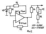
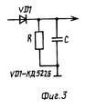
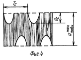
На фиг.1 показана структурная схема заявляемого устройства; на фиг.2 - схема источника опорного напряжения; на фиг.3 - схема амплитудного детектора; на фиг.4 - диаграмма напряжения на головке записи в стационарном режиме в заявляемом устройстве. Figure 1 shows the structural diagram of the inventive device; figure 2 - diagram of the source of the reference voltage; figure 3 is a diagram of an amplitude detector; figure 4 is a voltage diagram on the recording head in a stationary mode in the inventive device.
Устройство (фиг. 1) содержит последовательно соединенные усилитель записи 1 и фильтр высоких частот 2, последовательно соединенные первый сумматор 3, преобразователь напряжения в ток 4 и головку записи 5, сопряженную с магнитным носителем, генератор подмагничивания 11, выходом подключенный через управляемый усилитель 6 к одному входу первого сумматора, источник опорного напряжения 10, выходом подключенный к первому входу второго сумматора 8, а также двухполупериодный выпрямитель 9, включенный между выходом фильтра высоких частот и вторым входом второго сумматора амплитудный детектор 7, подключенный между выходом управляемого усилителя и третьим входом второго сумматора, выход которого соединен с управляющим входом управляемого усилителя, а выход усилителя записи подключен к другому входу первого сумматора. The device (Fig. 1) contains a series-connected recording amplifier 1 and a high-pass filter 2, a first adder 3 connected in series, a voltage to
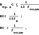
При разработке заявляемого устройства могут быть использованы: усилитель записи от любого серийно выпускаемого магнитофона без токостабилизирующих цепей, генератор подмагничивания - от любого серийно выпускаемого магнитофона с частотой генерации не менее 105 кГц, головка записи - любая универсальная или записывающая головка. Фильтр высоких частот выполнен по УИН-схеме управляемый усилитель - на основе операционного усилителя в неинвертирующем включении с полевым транзистором в заземленном плече делителя обратной связи; управляемый усилитель имеет линейно-спадающую зависимость коэффициента усиления от управляющего напряжения. Сумматор 3 выполнен по типовой резистивной схеме, сумматор 8 собран на операционном усилителе в неинвертирующем включении по типовой схеме; в случае применения управляемого усилителя с возрастающей зависимостью коэффициента усиления от управляющего напряжения сумматор 8 должен быть инвертирующим. Преобразователь напряжение-ток представляет собой резистор с сопротивлением, значительно превышающим полное сопротивление головки записи на максимальной рабочей частоте. Схема источника опорного напряжения приведена на фиг.2. В нем могут быть применены стабилитрон VD1-Д818Е, операционный усилитель DA1 - интегральная микросхема К140УД6, резистор R5 предназначен для регулировки выходного напряжения. Схема амплитудного детектора приведена на фиг.3. В нем может быть применен диод VD1-КД522Б. Номиналы резистора R и конденсатора С выбираются таким образом, чтобы выполнялись условия
![]()
![]()
Рассмотрена работа заявляемого устройства в стационарном режиме (при постоянной частоте и амплитуде входного информационного сигнала). Введены обозначения:
Uгсп - амплитуда напряжения подмагничивания на информационном входе управляемого усилителя (выходе генератора подмагничивания);
Uс - напряжение высокочастотной составляющей информационного сигнала на входе фильтра высоких частот (выходе усилителя записи);
Uоп - напряжение на выходе опорного источника;
Uподм - значение огибающей напряжения подмагничивания на выходе управляемого усилителя;
Ко - произведение коэффициента передачи фильтра высоких частот и коэффициента преобразования двухполупериодного выпрямителя для высокочастотной составляющей информационного сигнала записи.The operation of the claimed device in stationary mode (at a constant frequency and amplitude of the input information signal) is considered. The following notation is introduced:
U GSP - the bias voltage amplitude at the information input of a controlled amplifier (bias generator output);
U with - the voltage of the high-frequency component of the information signal at the input of the high-pass filter (output of the recording amplifier);
U op - voltage at the output of the reference source;
U subm is the value of the envelope of the bias voltage at the output of a controlled amplifier;
To about - the product of the transmission coefficient of the high-pass filter and the conversion coefficient of a half-wave rectifier for the high-frequency component of the recording information signal.
Коэффициент передачи управляемого усилителя 6 может быть записан в виде K1 - K2Uупр, где К1, К2 - константы.The transmission coefficient of the controlled amplifier 6 can be written in the form K 1 - K 2 U ctn , where K 1 , K 2 are constants.
Напряжение на выходе сумматора 8 (на управляющем входе усилителя 6) может быть записано следующим образом:
Uупр = ![]()
![]()
Uподм=Uгсп(K1-K2Uупр). Объединяя эти выражения, получают
Uподм = Uгсп ![]()
![]()
![]()
![]()
Uподм(1+UгспK2) + ![]()
![]()
1+UгспК2=UгспК2Ко, тогда
Uподм+![]()
![]()
![]()
U control = ![]()
![]()
U = U submanifold SHG (K 1 -K 2 Ex U). Combining these expressions gives
U subm = U gsp ![]()
![]()
![]()
![]()
U subm (1 + U gsp K 2 ) + ![]()
![]()
1 + U GSP K 2 = U GSP K 2 K o , then
U sub + ![]()
![]()
![]()
Диаграмма напряжения на головке записи в стационарном режиме представлена на фиг.4. Для огибающей напряжения подмагничивания можно записать
![]()
![]()
![]()
![]()

![]()
![]()
![]()
![]()
![]()
![]()
![]()
![]()

![]()
![]()
U![]()
![]()
![]()
![]()

![]()
![]()
![]()
![]()
![]()
![]()
![]()
![]()
![]()
![]()
![]()
![]()
![]()
![]()
![]()
U ![]()
![]()
![]()
![]()
![]()
Кроме того, из диаграммы видно, что диапазон динамического изменения напряжения подмагничивания в заявляемом устройстве в два раза больше, чем в прототипе, что приводит к расширению динамического диапазона для высокочастотных составляющих сигнала записи примерно на 6 дБ. In addition, the diagram shows that the range of dynamic changes in the bias voltage in the inventive device is two times greater than in the prototype, which leads to an expansion of the dynamic range for high-frequency components of the recording signal by about 6 dB.
Claims (1)
Priority Applications (1)
| Application Number | Priority Date | Filing Date | Title |
|---|---|---|---|
| SU4927510 RU2024964C1 (en) | 1991-04-18 | 1991-04-18 | Magnetic recording device provided with dynamic biasing |
Applications Claiming Priority (1)
| Application Number | Priority Date | Filing Date | Title |
|---|---|---|---|
| SU4927510 RU2024964C1 (en) | 1991-04-18 | 1991-04-18 | Magnetic recording device provided with dynamic biasing |
Publications (1)
| Publication Number | Publication Date |
|---|---|
| RU2024964C1 true RU2024964C1 (en) | 1994-12-15 |
Family
ID=21569758
Family Applications (1)
| Application Number | Title | Priority Date | Filing Date |
|---|---|---|---|
| SU4927510 RU2024964C1 (en) | 1991-04-18 | 1991-04-18 | Magnetic recording device provided with dynamic biasing |
Country Status (1)
| Country | Link |
|---|---|
| RU (1) | RU2024964C1 (en) |
-
1991
- 1991-04-18 RU SU4927510 patent/RU2024964C1/en active
Non-Patent Citations (3)
| Title |
|---|
| Авторское свидетельство СССР N 1185377, кл. G 11B 5/027, 1985. * |
| Авторское свидетельство СССР N 1539830, кл. G 11B 5/03, 20/00, 1986. * |
| Авторское свидетельство СССР N 1589317, кл. G 11B 5/027, 1987. * |
Similar Documents
| Publication | Publication Date | Title |
|---|---|---|
| US4180707A (en) | Distortion sound effects circuit | |
| US4014237A (en) | Musical note detecting apparatus | |
| US3971984A (en) | Wide-range logarithmic responding translation circuit | |
| RU2024964C1 (en) | Magnetic recording device provided with dynamic biasing | |
| JPS6351565B2 (en) | ||
| Campbell et al. | Noise from current-carrying resistors 20 to 500 kc | |
| US4187478A (en) | Noise reduction system having specific encoder circuitry | |
| Prestigiacomo | Amplitude contour display of sound spectrograms | |
| JP3336089B2 (en) | Signal processing device | |
| KR950012417A (en) | AC bias control device of magnetic recording head | |
| US2882352A (en) | D. c. amplifier system | |
| KR830002643B1 (en) | Audio frequency noise suppression circuit | |
| Duncan | Energy processing techniques for stress wave emission signals | |
| JP3147986B2 (en) | Expansion circuit | |
| Middlebrook | Optimum noise performance of transistor input circuits | |
| US3161730A (en) | Ultra-low frequency recording | |
| GB2136254A (en) | Impulse noise reduction by linear interpolation having a deemphasis characteristic | |
| SU1229807A1 (en) | Device for magnetic recording | |
| Grimwood | Volume compressors for sound recording | |
| SU1086495A1 (en) | Error compensator of current transformer | |
| SU1539830A1 (en) | Device for magnetic recording with adaptive magnetizing | |
| US3330966A (en) | Logarithmic converter circuit | |
| KR940008903B1 (en) | Current transformer | |
| RU1798746C (en) | Device for measurement of characteristics of magnetic materials | |
| KR830000872B1 (en) | Analog recorder using magnetic media |