RU2012603C1 - Apparatus for charging agglomerate on linear cooling equipment - Google Patents
Apparatus for charging agglomerate on linear cooling equipment Download PDFInfo
- Publication number
- RU2012603C1 RU2012603C1 SU5016622A RU2012603C1 RU 2012603 C1 RU2012603 C1 RU 2012603C1 SU 5016622 A SU5016622 A SU 5016622A RU 2012603 C1 RU2012603 C1 RU 2012603C1
- Authority
- RU
- Russia
- Prior art keywords
- partition
- agglomerate
- distance
- rear wall
- screen
- Prior art date
Links
- 238000001816 cooling Methods 0.000 title abstract description 16
- 238000005192 partition Methods 0.000 claims abstract description 35
- 239000002826 coolant Substances 0.000 claims abstract description 6
- 238000003860 storage Methods 0.000 claims description 2
- 239000011324 bead Substances 0.000 abstract 3
- 238000005272 metallurgy Methods 0.000 abstract 1
- 239000000126 substance Substances 0.000 abstract 1
- 239000000463 material Substances 0.000 description 19
- 230000007423 decrease Effects 0.000 description 12
- 230000002093 peripheral effect Effects 0.000 description 7
- 238000000034 method Methods 0.000 description 6
- 238000000926 separation method Methods 0.000 description 4
- 230000015572 biosynthetic process Effects 0.000 description 3
- 239000000428 dust Substances 0.000 description 3
- 238000005096 rolling process Methods 0.000 description 3
- XEEYBQQBJWHFJM-UHFFFAOYSA-N Iron Chemical compound [Fe] XEEYBQQBJWHFJM-UHFFFAOYSA-N 0.000 description 2
- 238000005265 energy consumption Methods 0.000 description 2
- 239000000203 mixture Substances 0.000 description 2
- 230000001105 regulatory effect Effects 0.000 description 2
- 238000012216 screening Methods 0.000 description 2
- 238000005245 sintering Methods 0.000 description 2
- 229910000831 Steel Inorganic materials 0.000 description 1
- 238000005056 compaction Methods 0.000 description 1
- 238000005516 engineering process Methods 0.000 description 1
- 239000004744 fabric Substances 0.000 description 1
- 238000001914 filtration Methods 0.000 description 1
- 239000007789 gas Substances 0.000 description 1
- 230000012447 hatching Effects 0.000 description 1
- 238000012432 intermediate storage Methods 0.000 description 1
- 229910052742 iron Inorganic materials 0.000 description 1
- 238000004519 manufacturing process Methods 0.000 description 1
- 238000002360 preparation method Methods 0.000 description 1
- 238000007789 sealing Methods 0.000 description 1
- 238000005204 segregation Methods 0.000 description 1
- 239000010959 steel Substances 0.000 description 1
- 238000005728 strengthening Methods 0.000 description 1
Images
Landscapes
- Manufacture And Refinement Of Metals (AREA)
Abstract
Description
Изобретение относится к подготовке железорудного сырья в черной металлургии, а именно к конструкции агломерационного оборудования. The invention relates to the preparation of iron ore in the steel industry, and in particular to the design of sintering equipment.
Известны устройства для загрузки агломерата на линейный охладитель, содержащие расположенный над колосниковым полотном с бортами наклонный в сторону полотна лоток [1] . Known devices for loading the agglomerate on a linear cooler containing located above the grate sheet with sides inclined to the side of the canvas tray [1].
Недостатками известных устройств являются загрузка крупных кусков агломерата преимущественно на поверхность и верхние горизонты слоя с уменьшением крупности загружаемых фракций сверху вниз. В тоже время крупные куски агломерата, обладающие высокой термической массивностью и тепловым потенциалом, омываются уже подогретым на средних и нижних горизонтах слоя воздухом. Пониженная величина разности температур охлаждающего агента и поверхности крупных кусков обусловливает уменьшение количества отнимаемого у них тепла. Кроме того, охлаждение крупных кусков осуществляется преимущественно путем отвода тепла теплопроводностью из центра куска к его поверхности, т. е. при отсутствии фильтрации охлаждающего агента через кусок, и является неэффективным. Такой режим охлаждения сопровождается увеличением его продолжительности, ростом капитальных, эксплуатационных и энергетических затрат. The disadvantages of the known devices are the loading of large pieces of agglomerate mainly on the surface and upper horizons of the layer with a decrease in the size of the loaded fractions from top to bottom. At the same time, large pieces of agglomerate, which have high thermal massiveness and thermal potential, are washed by air already warmed up at the middle and lower horizons of the layer. The reduced temperature difference between the cooling agent and the surface of large pieces causes a decrease in the amount of heat taken from them. In addition, the cooling of large pieces is carried out mainly by heat removal by heat conduction from the center of the piece to its surface, i.e., in the absence of filtering of the cooling agent through the piece, it is ineffective. This cooling mode is accompanied by an increase in its duration, an increase in capital, operating and energy costs.
За прототип принимает устройство для загрузки агломерата на линейный охладитель, содержащее расположенный над колосниковым полотном с бортами закрытый лоток с передней и задней по ходу движения полотна стенками и расположенными между ними грохотом и наклонной перегородкой [2] . The prototype is a device for loading agglomerate onto a linear cooler containing a closed tray located above the grate sheet with sides, with the front and rear walls and the screen and the inclined partition between them [2].
Недостатками данного устройства являются: а) изготовление грохота в виде свободно подвешенных пальцев, наклонных в сторону передней стенки лотка, нижняя кромка которых находится над верхней кромкой перегородки. При падении на такую систему больших масс материала, а агломерат поступает дискретно, значительными порциями (до 5 т с каждой паллеты), свободно подвешенные пальцеобразные элементы отклоняются и на наклонную перегородку попадают крупные куски, разделение агломерата по крупности нарушается. В результате крупные куски располагаются на поверхности слоя, происходит снижение производительности охладителя, рост капитальных, эксплуатационных и энергетических затрат; б) нерегламентированное соотношение расстояний между нижними кромками задней стенки, наклонной перегородки и полотном охладителя, приведет, во-первых, к увеличению вертикальной нагрузки от столба материала на полотно охладителя, во-вторых, к увеличению механической нагрузки на заднюю стенку загрузочного устройства при горизонтальном перемещении материала с полотном охладителя. Это приводит к увеличению капитальных и эксплуатационных затрат на охлаждение; в) отсутствие систем для формирования регламентированной поверхности слоя с предельной по высоте нагрузкой охладителя. В результате имеет место снижение производительности охладителя, повышение удельного расхода воздуха на охлаждение и, как следствие, увеличение энергетических расходов. The disadvantages of this device are: a) the manufacture of a screen in the form of freely suspended fingers, inclined toward the front wall of the tray, the lower edge of which is above the upper edge of the partition. When large masses of material fall onto such a system, and the agglomerate arrives discretely, in significant portions (up to 5 tons from each pallet), the freely suspended finger-like elements are deflected and large pieces fall on the inclined partition, the separation of the agglomerate by size is disturbed. As a result, large pieces are located on the surface of the layer, there is a decrease in the performance of the cooler, an increase in capital, operating and energy costs; b) the unregulated ratio of the distances between the lower edges of the rear wall, the inclined partition and the cooler web will lead, firstly, to an increase in the vertical load from the column of material on the cooler web, and secondly, to an increase in the mechanical load on the back wall of the loading device during horizontal movement material with a cloth of a cooler. This leads to an increase in capital and operating costs for cooling; c) the absence of systems for the formation of a regulated surface of the layer with a maximum height load of the cooler. As a result, there is a decrease in the performance of the cooler, an increase in the specific air consumption for cooling, and, as a result, an increase in energy costs.
Целью предлагаемого изобретения является повышение производительности охладителя, снижение выбросов пыли и расхода электроэнергии. The aim of the invention is to increase the performance of the cooler, reducing dust emissions and energy consumption.
Цель достигается при использовании устройства для загрузки агломерата на линейный охладитель, содержащего расположенный над колосниковым полотном с бортами закрытый лоток с передней и задней по ходу движения полотна стенками и расположенной между ними перегородкой и грохотом. Согласно изобретения, передняя и задняя стенки лотка и перегородка выполнены наклонными в сторону движения полотна, грохот установлен наклонно навстречу движению охладителя и скреплен с верхней частью перегородки и задней стенкой, образующими между собой и боковыми стенками лотка бункер-накопитель. Лоток снабжен подвижными ограничителями высоты слоя, размещенными на нижней части задней стенки на центральном участке горизонтально, а на боковых - наклонно к бортам охладителя под углом 30-40о к горизонтали.The goal is achieved when using the device for loading the agglomerate on a linear cooler, containing a closed tray located above the grate sheet with sides, with the front and rear walls in the direction of movement of the sheet and a partition between them and a screen. According to the invention, the front and rear walls of the tray and the partition are made inclined towards the web, the screen is mounted obliquely to the movement of the cooler and fastened to the upper part of the partition and the rear wall, which form a storage hopper between themselves and the side walls of the tray. The tray is provided with a movable bed height limiters arranged at the lower portion of the rear wall horizontally in the central portion, and the side - obliquely to the sides of the coolant at an angle of 30-40 to the horizontal.
На конвейерных охладителях с известными устройствами крупные куски агломерата (более 60-80 мм) подаются преимущественно на поверхность слоя. Охлаждение таких кусков лимитирует весь процесс охлаждения слоя, обусловливает увеличение продолжительности процесса и энергетических затрат на него. Подача крупных кусков агломерата на нижние горизонты слоя, причем в окружности мелких и средних фракций материала, обусловливает подвод к крупным кускам наиболее холодного охлаждающего агента, увеличивает его количество, фильтрующегося через кусок и существенно интенсифицирует процесс охлаждения слоя. Для этого необходимо надежное и по возможности полное отделение крупных кусков агломерата от его остальной массы, подачу этих крупных кусков на нижний горизонт слоя отдельным потоком и окружение этих кусков укладываемыми сверху средними и мелкими фракциями. Надежных методов решения поставленной задачи до настоящего времени не существует. В прототипе отделение крупных кусков от основной массы материала, а также укладка агломерата на охладитель без его подуплотнения по существу также остались нерешенными. В предлагаемом изобретении разработано устройство для загрузки агломерата со стационарной системой его предварительного грохочения и последующей укладкой материала различной крупности с ограниченным давлением столба материала на колосниковое полотно и горизонтальной нагрузки на заднюю стенку. Устройство имеет следующие отличительные особенности. On conveyor coolers with known devices, large pieces of sinter (more than 60-80 mm) are fed mainly to the surface of the layer. The cooling of such pieces limits the entire process of cooling the layer, causes an increase in the duration of the process and energy costs for it. The supply of large pieces of agglomerate to the lower horizons of the layer, and in the circumference of small and medium fractions of the material, causes the coolest cooling agent to be supplied to large pieces, increases its amount, filtered through the piece and significantly intensifies the process of cooling the layer. For this, reliable and, as far as possible, complete separation of large pieces of agglomerate from its remaining mass, the supply of these large pieces to the lower horizon of the layer in a separate stream, and the surroundings of these pieces stacked on top of medium and small fractions are necessary. Reliable methods for solving the problem to date do not exist. In the prototype, the separation of large pieces from the bulk of the material, as well as the laying of the agglomerate on a cooler without its compaction essentially also remained unresolved. In the present invention, a device for loading agglomerate with a stationary system for preliminary screening and subsequent laying of material of various sizes with limited pressure of a column of material on the grate sheet and horizontal load on the back wall is developed. The device has the following distinctive features.
Закрытый загрузочный лоток с целью надежного отделения крупных кусков от остальной массы агломерата должен быть оборудован наклонным навстречу движения колосникового полотна грохотом. Этот грохот устанавливают под углом 30-40о к горизонту и выполняют с отверстиями (щелями) 60-90 мм, причем размер отверстий по ходу движения агломерата по грохоту изготовлен постепенно возрастающим от 60-80 до 70-90 мм. Тем самым обеспечивается надежное отгрохочивание кусков крупностью более 60 мм из всего потока материала и передача крупных кусков на отдельный наклонный транспортирующий лоток - переднюю стенку.In order to reliably separate large pieces from the rest of the agglomerate mass, the closed loading tray should be equipped with a screen that is inclined towards the movement of the grate sheet. This rumble set at an angle of 30-40 to the horizontal and operate with holes (slits) 60-90 mm, the opening size of the agglomerate during the movement of the thunder is made gradually increases from 60-80 to 70-90 mm. This ensures reliable hatching of pieces larger than 60 mm from the entire material flow and transfer of large pieces to a separate inclined conveying tray - the front wall.
Под грохотом должен быть расположен наклонный по ходу движения колосникового полотна лоток - промежуточная наклонная перегородка. Эта перегородка предназначена для приема и транспортировки отсеваемых на грохоте средних и мелких фракций агломерата. Передняя стенка лотка предназначена для приема и транспортировки крупных кусков агломерата. Under the screen, a tray inclined in the direction of movement of the grate should be located - an intermediate inclined partition. This partition is designed for receiving and transporting medium and small agglomerate fractions sifted out at a screen. The front wall of the tray is designed to receive and transport large pieces of agglomerate.
Грохот и перегородка с одной стороны (в месте разгрузки крупных кусков агломерата с грохота) состыкованы между собой. Тем самым, обеспечивается надежная передача крупных кусков агломерата на переднюю стенку лотка, минуя перегородку и герметизация системы для снижения запыленности окружающей среды. С другой стороны грохот состыкован с задней стенкой - по существу ограничительной стенкой. Таким образом, грохот, перегородка и задняя ограничительная стенка образуют между собой закрытую систему - промежуточный накопительный бункер средних и мелких фракций агломерата, чем обеспечивается, во-первых, постоянная во времени подача агломерата на колосниковое полотно, во-вторых, возможность регулирования давления столба шихты на полотно, в третьих, загрузку средних и мелких фракций агломерата поверх крупных кусков, причем средних фракций преимущественно на верхний горизонт, что существенно понижает запыленность окружающей среды. The screen and the partition on one side (at the place of unloading of large pieces of agglomerate from the screen) are docked together. This ensures reliable transfer of large pieces of agglomerate to the front wall of the tray, bypassing the partition and sealing the system to reduce dust in the environment. On the other hand, the screen is docked with the rear wall - essentially a bounding wall. Thus, the screen, the partition and the rear boundary wall form a closed system between themselves - an intermediate storage hopper of medium and small fractions of the agglomerate, which ensures, firstly, a constant flow of agglomerate to the grate, and secondly, the ability to control the pressure of the charge column onto the canvas, thirdly, loading medium and small agglomerate fractions on top of large pieces, with medium fractions predominantly on the upper horizon, which significantly reduces the dust content of the environment .
На нижней части задней стенки должны быть установлены подвижные ограничители высоты слоя, изготовляемые в поворотном исполнении для их защиты от деформации при случайных перегрузках. Эти ограничители выравнивают слой по длине ленты и формируют при этом заданный профиль слоя по ширине ленты. На центральных участках слоя (0,7-0,8 его ширины) нижняя кромка ограничителей выполнена горизонтальной и обеспечивает формирование горизонтального участка слоя высотой, превышающей высоту бортов колосникового полотна. На периферийных участках слоя ограничители выполнены наклонными от уровня ограничителей центрального участка в сторону верхней кромки бортов. При этом для исключения скатывания агломерата с охладителя угол наклона ограничителей не должен превысить угол естественного откоса материала. Таким образом, на колосниковом полотне формируют высокий слой стационарный по длине и по ширине полотна, что существенно интенсифицирует процесс охлаждения агломерата. On the lower part of the back wall, movable layer height limiters should be installed, manufactured in a rotary design to protect them from deformation in case of accidental overloads. These stops align the layer along the length of the tape and at the same time form a predetermined layer profile along the width of the tape. In the central sections of the layer (0.7-0.8 of its width), the lower edge of the limiters is made horizontal and provides the formation of a horizontal section of the layer with a height exceeding the height of the sides of the grate blade. In the peripheral sections of the layer, the limiters are made inclined from the level of the limiters of the central section towards the upper edge of the sides. At the same time, to prevent the agglomerate from rolling off the cooler, the angle of inclination of the limiters should not exceed the angle of natural slope of the material. Thus, a high layer is formed on the grate web, stationary along the length and width of the web, which significantly intensifies the agglomerate cooling process.
Наклон ограничителей на периферийных участках устройства должен составлять 30-40о к горизонтали. При меньшем угле наклона ограничителей (менее 30о к горизонтали) материал с охладителей уже не выпадает, а высота слоя на полотне искусственно занижается, т. е. уменьшается производительность агрегата. При большем угле наклона ограничителей (более 40о) часть агломерата скатывается с охладителя, что, во-первых, недопустимо по условиям эксплуатации, во-вторых, также обусловливает понижение производительности охладителя.The slope of the limiters on the peripheral sections of the device should be 30-40 about to the horizontal. With a smaller angle of inclination of the limiters (less than 30 degrees to the horizontal), the material does not drop out from the coolers, and the layer height on the canvas is artificially lowered, i.e., the unit’s productivity decreases. At a larger angle of inclination of the limiters (more than 40 ° ), part of the agglomerate rolls off the cooler, which, firstly, is unacceptable under operating conditions, and secondly, also causes a decrease in the performance of the cooler.
Нижние кромки перегородки и задней стенки должны быть расположены на регламентированном расстоянии друг от друга и колосникового полотна. Тем самым обеспечивается формирование всех элементов охлаждаемого слоя. Расстояние по горизонтали между нижними кромками задней стенки и перегородки должно составлять 0,1-0,2 величины по горизонтали выходного отверстия бункера, образованного перегородкой и задней стенкой. При меньшем расстоянии между нижними кромками задней стенки и перегородки (менее 0,1 величины выходного отверстия бункера) становится возможным кострение материала, как следствие, аварийный останов агрегата и снижение его удельной производительности. При большем расстоянии между нижними кромками задней стенки и перегородки (более 0,2 величины выходного отверстия бункера) происходит увеличение давления на полотно охладителя, увеличение механической нагрузки на заднюю стенку и необходимость в значительном ее укреплении, что приводит к росту капитальных и эксплуатационных затрат. The lower edges of the partition and the back wall should be located at a regulated distance from each other and the grate. This ensures the formation of all elements of the cooled layer. The horizontal distance between the lower edges of the rear wall and the partition should be 0.1-0.2 horizontal values of the outlet of the hopper formed by the partition and the rear wall. With a smaller distance between the lower edges of the rear wall and the partition (less than 0.1 of the outlet size of the hopper), it becomes possible to make a material fire, as a result, an emergency stop of the unit and a decrease in its specific productivity. With a greater distance between the lower edges of the rear wall and the partition (more than 0.2 of the hopper outlet), there is an increase in pressure on the cooler web, an increase in the mechanical load on the back wall and the need for significant strengthening of it, which leads to an increase in capital and operating costs.
Расстояние между нижней кромкой перегородки и колосниковым полем должно быть выполнено равным 0,5-0,7 высоты бортов. При меньшем расстоянии между нижней кромкой перегородки и колосниковым полем (менее 0,5 высоты бортов) возможно кострение крупных кусков материала скользящих по передней стенке и загружающихся на полотно охладителя, вплоть до выхода из строя перегородки, что увеличивает эксплуатационные затраты, снижает производительность охладителя. При большем расстоянии (более 0,7 высоты бортов) между нижней кромкой перегородки и колосниковым полотном сужается выходное отверстие бункера, образованного перегородкой и задней стенкой и, как следствие, возможно кострение материала в бункере, аварийный останов охладителя. В результате снижается производительность агрегата, растут эксплуатационные расходы на охлаждение. The distance between the lower edge of the partition and the grate field should be equal to 0.5-0.7 of the height of the sides. With a smaller distance between the lower edge of the partition and the grate field (less than 0.5 height of the sides), large pieces of material can slide around the front wall and load onto the cooler web, up to the failure of the partition, which increases operating costs and reduces the performance of the cooler. With a larger distance (more than 0.7 of the side height) between the lower edge of the partition and the grate, the outlet opening of the hopper, formed by the partition and the back wall, narrows and, as a result, material can be bonded in the hopper and the cooler will stop. As a result, the performance of the unit decreases, operating costs for cooling increase.
Сущность изобретения заключается в оборудовании устройства для загрузки на линейный охладитель агломерата стационарной неподвижной системой грохочения с выделением крупных кусков в нижний горизонт слоя, окружение этих кусков мелочью и укладка сверху остального потока материала при подаче его стесненным потоком с ограниченным давлением столба материала на колосниковое полотно и механической нагрузкой на заднюю стенку при движении колосникового полотна. The essence of the invention is to equip a device for loading onto a linear cooler of sinter stationary stationary screening system with the separation of large pieces in the lower horizon of the layer, surrounding these pieces with fines and laying on top of the rest of the material stream when it is fed with a cramped stream with limited column pressure of material on the grate sheet and mechanical the load on the back wall when moving the grate.
Неизвестны технические решения, которые содержат признаки, совпадающие с признаками, отличающими предлагаемое решение от прототипа, т. е. заявленное изобретение соответствует критерию "существенные отличия". Unknown technical solutions that contain features that match the features that distinguish the proposed solution from the prototype, that is, the claimed invention meets the criterion of "significant differences".
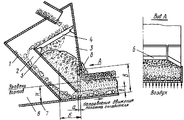
На чертеже представлены продольный и поперечный разрезы устройства для загрузки агломерата на линейный охладитель. The drawing shows a longitudinal and transverse sections of a device for loading sinter on a linear cooler.
Устройство состоит из закрытого лотка с передней 1, боковыми 2 и задней 3 стенками, грохота 4, перегородки 5 и размещенных на задней стенке ограничителей слоя 6. Устройство размещено над колосниковым полотном 7 с бортами 8. The device consists of a closed tray with front 1, side 2 and rear 3 walls,
Устройство работает следующим образом. Разгружаемый с агломашины агломерат подают в закрытый лоток, а оттуда на грохот 4. Сходящий по этому грохоту материал разделяется на крупную (более 60-90 мм) фракцию и смесь средней и мелкой фракций. Крупная фракция агломерата скатывается по грохоту 4, поступает на переднюю стенку 1 и оттуда на поверхность колосникового полотна 7 (т. е. в нижний горизонт формируемого слоя). Средние и мелкие фракции агломерата проваливаются через щели грохота 4 и поступают в бункер, образованный перегородкой 5, задней стенкой 3 и боковыми стенками 2, подвергаются в нем сегрегации и поступают на колосниковое полотно 7 поверх крупных кусков. Смесь мелких и средний фракций окружает крупные куски и располагается преимущественно на среднем горизонте слоя. Средние фракции попадают преимущественно на верхний горизонт слоя. Сформированный таким образом слой разравнивается ограничителями 6 до заданного технологией профиля с понижением высоты слоя к бортам колосникового полотна и подвергается охлаждению. The device operates as follows. The agglomerate discharged from the sintering machine is fed to a closed tray, and from there to a
П р и м е р 1. На средние конструктивные параметры. PRI me R 1. On average design parameters.
Расстояние по горизонтали между нижними кромками задней стенки и перегородки а (см. чертеж выполнено равным 0,15 величины по горизонтали выходного отверстия бункера, образованного перегородкой и задней стенкой б. Расстояние между нижней кромкой перегородки и колосниковым полем b выполнено равным 0,6 высоты бортов H. Угол наклона ограничителей на периферийных участках системы составляет 35о к горизонту.The horizontal distance between the lower edges of the rear wall and the partition a (see drawing is equal to 0.15 of the horizontal value of the outlet of the hopper formed by the partition and the rear wall b. The distance between the lower edge of the partition and the grate field b is equal to 0.6 of the side height H. The angle of the limiters in the peripheral parts of the system is 35 about to the horizon.
При таких параметрах устройства производительность охладителя с площадью 315 м2 и высотой бортов 0,7 м составляет 485 т/ч, расход электроэнергии 6,2 кВтч/т агломерата.With these parameters of the device, the capacity of the cooler with an area of 315 m 2 and a side height of 0.7 m is 485 t / h, electric power consumption is 6.2 kWh / t of sinter.
Серийные линейные охладители агломерата типа ОП-315 имеют производительность 350-400 т/ч, расход электроэнергии 7,5-8,5 кВтч/т. Series linear sinter coolers of the OP-315 type have a capacity of 350-400 t / h and an electric power consumption of 7.5-8.5 kWh / t.
Таким образом, предлагаемое решение превосходит известное по указанным показателям. Thus, the proposed solution is superior to the known indicators.
П р и м е р 2. На минимальные значения конструктивных параметров и на отклонения от них. PRI me R 2. On the minimum values of design parameters and deviations from them.
Расстояние b выполнено равным 0,5 высоты бортов. Расстояние a изготовлено равным 0,10 расстояния Б. Угол наклона ограничителей на периферийных участках системы составляет 30о к горизонту.The distance b is made equal to 0.5 side height. The distance a is made equal to 0.10 of the distance B. The angle of inclination of the limiters in the peripheral parts of the system is 30 about to the horizon.
При таких параметрах устройства производительность охладителя ОП-315 составит 460 т/ч, расход электроэнергии 6,5 кВтч/т. With these parameters of the device, the capacity of the OP-315 cooler will be 460 t / h, and the electric power consumption will be 6.5 kWh / t.
Понижение расстояния b возможно только до величины 0,5 высоты бортов. Так, при расстоянии b, равном 0,4 высоты бортов, из-за кострения материала и простоев удельная производительность охладителя сокращается на 14,2% . Reducing the distance b is only possible to a value of 0.5 side height. So, at a distance b equal to 0.4 of the height of the sides, due to the coring of the material and downtime, the specific performance of the cooler is reduced by 14.2%.
Понижение расстояния a возможно только до величины 0,10 расстояния Б. Так, при расстоянии a, равном 0,08 расстояния Б, из-за кострения материала и простоев охладителя, его производительность понижается до 440 т/ч и возрастает запыленность окружающего пространства. Reducing the distance a is possible only to the value 0.10 of the distance B. So, at a distance a equal to 0.08 of the distance B, due to the material’s crowning and cooler downtime, its productivity decreases to 440 t / h and the dustiness of the surrounding space increases.
Понижение угла наклона периферийных ограничителей слоя возможно только до величины 30о к горизонту. Например, при угле наклона равном 27о, при отсутствии скатывания агломерата с охладителя, его удельная производительность сокращается на 2,4% .Reducing the angle of inclination of the peripheral limiters of the layer is possible only up to a value of 30 about to the horizon. For example, an inclination angle equal to about 27, in the absence of rolling to sinter cooler, its specific capacity is reduced by 2.4%.
П р и м е р 3. . На максимальные значения конструктивных параметров и на отклонения от них. PRI me R 3.. The maximum values of the design parameters and deviations from them.
Расстояние b выполнено равным 0,7 высоты бортов. Расстояние a изготовлено равным 0,2 расстояния Б. Угол наклона периферийных ограничителей составляет 40о к горизонту.The distance b is equal to 0.7 of the height of the sides. The distance a is made equal to 0.2 of the distance B. The angle of inclination of the peripheral limiters is 40 ° to the horizon.
При таких параметрах устройства производительность охладителя ОП-315 составит 465 т/ч, расход электроэнергии 6,45 кВтч/т. With these device parameters, the capacity of the OP-315 cooler will be 465 t / h, and the electric power consumption will be 6.45 kWh / t.
Повышение расстояния b возможно только до величины 0,7 высоты бортов. Уже при b = 0,8 H, из-за кострения материала и простоев охладителя снижается производительность до 435 т/ч. Increasing the distance b is possible only up to 0.7 of the height of the sides. Already at b = 0.8 H, due to material crusting and downtime of the cooler, productivity decreases to 435 t / h.
Повышение расстояния a возможно только до величины 0,2 расстояния Б. Так, при расстоянии a, равном 0,3 расстояния Б, из-за увеличения давления на полотно охладителя и на заднюю стенку в процессе движения полотна увеличиваются капитальные и эксплуатационные расходы на охлаждение, себестоимость агломерата возрастает на 1,5 руб/т. Increasing the distance a is possible only up to the value 0.2 of the distance B. So, with a distance a equal to 0.3 of the distance B, due to the increase in pressure on the cooler sheet and on the rear wall, the capital and operating costs for cooling increase during the movement of the sheet, the cost of sinter increases by 1.5 rubles / t.
Повышение угла наклона периферийных ограничителей возможно только до величины 40о к горизонту, Так, при угле наклона равном 45о, из-за скатывания агломерата с охладителя, его производительность уменьшается на 8,1% .Increasing the angle of the peripheral limiters only possible to a value of about 40 to the horizontal, For example, an inclination angle equal to about 45, due to rolling of the agglomerate with a cooler, its performance is reduced by 8.1%.
Серийные линейные охладители типа ОП-315 Карагандинского меткомбината имеют производительность 350-400 т/ч, расход электроэнергии на охлаждение 7,5-8,5 кВтч/т агломерата. Series linear coolers of the type OP-315 of the Karaganda metallurgical plant have a capacity of 350-400 t / h, and the electric power consumption for cooling is 7.5-8.5 kWh / t sinter.
Применение предлагаемого изобретения обеспечивает повышение производительности охладителей на 20-30% , сокращение расхода электроэнергии на 17-30% и понижение запыленности цехового помещения и отводимых с охладителя газов. При таком улучшении параметров процесса себестоимость агломерата понижается на 0,4 руб/т. The application of the invention provides an increase in the performance of coolers by 20-30%, a reduction in energy consumption by 17-30% and a decrease in the dustiness of the workshop premises and the gases discharged from the cooler. With this improvement in process parameters, the cost of sinter is reduced by 0.4 rubles / t.
Claims (2)
Priority Applications (1)
| Application Number | Priority Date | Filing Date | Title |
|---|---|---|---|
| SU5016622 RU2012603C1 (en) | 1991-12-16 | 1991-12-16 | Apparatus for charging agglomerate on linear cooling equipment |
Applications Claiming Priority (1)
| Application Number | Priority Date | Filing Date | Title |
|---|---|---|---|
| SU5016622 RU2012603C1 (en) | 1991-12-16 | 1991-12-16 | Apparatus for charging agglomerate on linear cooling equipment |
Publications (1)
| Publication Number | Publication Date |
|---|---|
| RU2012603C1 true RU2012603C1 (en) | 1994-05-15 |
Family
ID=21591595
Family Applications (1)
| Application Number | Title | Priority Date | Filing Date |
|---|---|---|---|
| SU5016622 RU2012603C1 (en) | 1991-12-16 | 1991-12-16 | Apparatus for charging agglomerate on linear cooling equipment |
Country Status (1)
| Country | Link |
|---|---|
| RU (1) | RU2012603C1 (en) |
-
1991
- 1991-12-16 RU SU5016622 patent/RU2012603C1/en active
Similar Documents
| Publication | Publication Date | Title |
|---|---|---|
| RU2524287C2 (en) | Agglomerate loading chute | |
| CN211964515U (en) | Manganese ore pellet preparation system | |
| RU2012603C1 (en) | Apparatus for charging agglomerate on linear cooling equipment | |
| CN202432858U (en) | Discharge chute of sintering machine | |
| EP0044853B1 (en) | Device for sealing a fluidized bed | |
| JPH07332827A (en) | Two layer cooler | |
| GB1429603A (en) | Sintering platn for producing sinter from iron ore | |
| CN113639552B (en) | Bottom edge material supply system and method for belt roasting machine | |
| CN212856515U (en) | Processing device for reducing crushing rate of dust mud dry balls | |
| JPS5925011B2 (en) | Sinter cooling equipment | |
| KR20040098471A (en) | A mineral charge guide sintering mineral cooler | |
| SU981407A1 (en) | Method for charging agglomerate into a crossed-current cooler | |
| CN219869026U (en) | Drying bin aggregate system | |
| JPH031067Y2 (en) | ||
| SU755844A1 (en) | Two-step method of pellet cooling | |
| SU1740933A1 (en) | Device for sinter transfer from machine to cooler | |
| RU2817875C1 (en) | Section of discharge grate for device for grinding solid materials and discharge grate containing it, device for grinding solid materials and line for processing wastes of metallurgical production | |
| SU1154957A1 (en) | Multiple-section apparatus for working fine particulate materials | |
| JPH062912B2 (en) | Pretreatment method of raw material for smelting furnace | |
| SU1280035A1 (en) | Method of treating loose materials in fluidized bed and device for effecting same | |
| SU765617A1 (en) | Apparatus for heat treatment of pulverulent materials | |
| JPS62227047A (en) | Transferring method for sintered ore | |
| SU1532791A1 (en) | Charging arrangement for conveyer-type sinter cooler | |
| JPS62199735A (en) | Method for supplying sintered ore to sintering and cooling machine | |
| SU931769A1 (en) | Method of producing agglomerate |