RU17536U1 - METAL FURNACE FURNACE - Google Patents
METAL FURNACE FURNACE Download PDFInfo
- Publication number
- RU17536U1 RU17536U1 RU2000128282/20U RU2000128282U RU17536U1 RU 17536 U1 RU17536 U1 RU 17536U1 RU 2000128282/20 U RU2000128282/20 U RU 2000128282/20U RU 2000128282 U RU2000128282 U RU 2000128282U RU 17536 U1 RU17536 U1 RU 17536U1
- Authority
- RU
- Russia
- Prior art keywords
- pipe
- chamber
- melting chamber
- furnace
- furnace according
- Prior art date
Links
- 239000002184 metal Substances 0.000 title claims abstract description 20
- 229910052751 metal Inorganic materials 0.000 title claims abstract description 20
- 238000002844 melting Methods 0.000 claims abstract description 29
- 230000008018 melting Effects 0.000 claims abstract description 29
- 239000002893 slag Substances 0.000 claims abstract description 13
- 239000010425 asbestos Substances 0.000 claims description 2
- 229910052895 riebeckite Inorganic materials 0.000 claims description 2
- 206010022000 influenza Diseases 0.000 claims 1
- RYGMFSIKBFXOCR-UHFFFAOYSA-N Copper Chemical compound [Cu] RYGMFSIKBFXOCR-UHFFFAOYSA-N 0.000 abstract description 5
- 238000003723 Smelting Methods 0.000 abstract description 4
- 229910052802 copper Inorganic materials 0.000 abstract description 3
- 239000010949 copper Substances 0.000 abstract description 3
- -1 ferrous metals Chemical class 0.000 abstract description 2
- 238000009856 non-ferrous metallurgy Methods 0.000 abstract description 2
- 238000005868 electrolysis reaction Methods 0.000 abstract 1
- 238000004519 manufacturing process Methods 0.000 abstract 1
- 239000007789 gas Substances 0.000 description 23
- 230000006378 damage Effects 0.000 description 3
- 238000000034 method Methods 0.000 description 3
- 150000002739 metals Chemical class 0.000 description 2
- VNWKTOKETHGBQD-UHFFFAOYSA-N methane Chemical compound C VNWKTOKETHGBQD-UHFFFAOYSA-N 0.000 description 2
- 238000004140 cleaning Methods 0.000 description 1
- 239000011248 coating agent Substances 0.000 description 1
- 238000000576 coating method Methods 0.000 description 1
- 238000002485 combustion reaction Methods 0.000 description 1
- 238000001816 cooling Methods 0.000 description 1
- 239000003792 electrolyte Substances 0.000 description 1
- 238000010438 heat treatment Methods 0.000 description 1
- 238000009434 installation Methods 0.000 description 1
- 239000000155 melt Substances 0.000 description 1
- 239000003345 natural gas Substances 0.000 description 1
- 238000005096 rolling process Methods 0.000 description 1
- 238000009423 ventilation Methods 0.000 description 1
Landscapes
- Manufacture And Refinement Of Metals (AREA)
- Waste-Gas Treatment And Other Accessory Devices For Furnaces (AREA)
Abstract
РЕФЕРАТESSAY
к свидетельству РФ на полезную модель №под названием «Печь для плавкиto the certificate of the Russian Federation for a utility model No.
металла.metal.
Данное предложение относится к области цветной металлургии и может быть использовано в печах для плавки и изготовления анодов из черновой меди для чистой меди путем электролизаThis proposal relates to the field of non-ferrous metallurgy and can be used in furnaces for smelting and manufacturing of blister copper anodes for pure copper by electrolysis
Технической задачей предлагаемого решения является увеличение стойкости узла соединения газоотводящего тракта плавильной камеры и сокращение затрат в процессе эксплуатации.The technical objective of the proposed solution is to increase the durability of the connection node of the exhaust gas duct of the melting chamber and reduce costs during operation.
Указанная техническая задача достигается тем, что газоотводящая магистраль снабжена дополнительно шарнирным узлом, расположенным между камерой и шлаковой емкостью и выполненным в виде двух жестких коробов, установленных на жесткой трубе с вырезами.The specified technical problem is achieved by the fact that the exhaust pipe is additionally equipped with a hinge assembly located between the chamber and the slag tank and made in the form of two rigid ducts mounted on a rigid pipe with cutouts.
Использование дашюго технического решения позволяет увеличить стойкость узла соединения в 3-5 раз, упростить конструкцию газоходного тракта и снизить эксплуатщионные затраты на 20-30% по сравнению с известными конструкциями плавильных печей, преимущественно для цветных металлов. Using a technical solution allows to increase the durability of the connection node by 3-5 times, simplify the design of the gas duct and reduce operating costs by 20-30% compared with the known designs of smelting furnaces, mainly for non-ferrous metals.
Description
Печь для плавкш металлов.Furnace for floating metals.
Предлагаемое техническое решение относится к области цветной металлургии и может быть использовано в печах для получения черновой меди методом плавки с использованием природного газа.The proposed solution relates to the field of non-ferrous metallurgy and can be used in furnaces for producing blister copper by melting using natural gas.
Известны печи для плавки металла, преимущественно меди, содержащие поворотную плавильную камеру с загрузочными и разгрузочными окнами, неподвижную щлаковую камеру, соединенную с поворотнойKnown furnaces for melting metal, mainly copper, containing a rotary melting chamber with loading and unloading windows, a fixed slag chamber connected to a rotary
плавильной камерой газоходом, установленный в центре поворота плавильной камеры На боковой поверхности плавильной камеры над загрузочными окнами закреплена газоотводящая магистраль , которая соединяется с газовым трактом шлаковой камеры. Узел соединения магистрали с трактом выполнен в виде гибкого шланга , жестко закрепленного на кошдах последних. Нагрев и плавление металла осуществляется с помощью газовых горелок, установленных внутри плавильной камеры ( см. нагфимер чертеж № 258-0409-ТМ-1 на поворотную печь для плавки металла, разр отанную Уралэлектромедь для Кьшпымского медеэлектролитного завода за 1992г.)a melting chamber with a gas duct installed in the center of rotation of the melting chamber On the side surface of the melting chamber above the loading windows, a gas exhaust duct is fixed, which is connected to the gas path of the slag chamber. The node connecting the highway with the path is made in the form of a flexible hose, rigidly fixed to the coders of the latter. Heating and melting of the metal is carried out using gas burners installed inside the melting chamber (see Nagfimer drawing No. 258-0409-TM-1 for a rotary furnace for melting metal, developed by Uralelectromed for the Kshpym copper electrolyte plant for 1992)
Недостатком этого вида печей является быстрое разрушение узла соединения магистрали с трактом под воздействием высоких температур и агрессивной среды в отходящих газах В результате требуется частая замена всего узла в целом, что снижает производительность печи, т.к. на замену уходит значительное количество времени и требуется охлаждение всего тракта перед заменойThe disadvantage of this type of furnace is the rapid destruction of the node connecting the line with the tract under the influence of high temperatures and aggressive environment in the exhaust gases. As a result, frequent replacement of the entire unit as a whole is required, which reduces the productivity of the furnace, because Replacement takes a significant amount of time and requires cooling the entire path before replacing
Как же известны поворотные печи, у которых газоотводящий тракт выполнен в виде поворотных зонтов, установленных на дополнительныхHow rotary furnaces are known, in which the gas exhaust path is made in the form of rotary umbrellas mounted on additional
;--: :f ,,-l.i f .. . Ji. ,„, .. - 1„ ,,.,., .....; -:: f ,, - l.i f ... Ji. ,", .. - 1" ,,.,., .....
МКИ C22B15/02 MKI C22B15 / 02
опорах возле окон загрузки и поворачиваются к печи только при вертикальном расположении печи и открытых окнах. Выходы всех зонтов соединены сsupports near the loading windows and turn to the furnace only with the vertical arrangement of the furnace and open windows. The outputs of all umbrellas are connected to
газоотводшцим трактом в виде вентиляционных труб ( см. « - исРАГ Г ло . /. .gas outlet in the form of ventilation pipes (see. - ISRAG GL. /.
Недостатком этих печей яамется то, что опоры занимают значительное пространство и мешают загрузочным машинам производить завалку шихты . Это требует от оператора машины особых осторожных действий , чтобы не разрушить стойки и не повредить саму систему газоотвода в процессе загрузки, что делает их неудобными в процессе эксплуатации.The disadvantage of these furnaces is that the supports occupy a considerable space and prevent the loading machines from filling the charge. This requires special care from the machine operator so as not to destroy the racks and not damage the gas exhaust system itself during the loading process, which makes them inconvenient during operation.
Технической задачей предлагаемого решения - является исключение разрушения узла соединения поворотной части газоотводяшей магастрали с неподвижным трактом с одновременным сокрашением эксплуатационных затрат и повышением производительности плавильных агрегатов в процессе эксплуатации.The technical task of the proposed solution is to eliminate the destruction of the junction of the rotary part of the exhaust gas line with a fixed path while reducing operating costs and increasing the productivity of the melting units during operation.
Указанная техническая задача достигается тем, что в устройстве для плавки металла, содержащем поворотную плавильную камеру и неподвижную шлаковую емкость соединенные между собой газоходом, центральная продольная ось которого совпадает с центром вращения плавильной камеры, а на боковой поверхности над загрузочными окнами плавильной камеры и шлаковой емкости установлена газоотводящая магистраль при этом , газоотводящая малистраль снабжена дополнительно шарнирным узлом, размешенным между плавильной камерой и шлаковой емкостью, выполненным из жесткой трубы с радиальными вырезами, на которой с возможностью поворота установлены два жестких короба, каждый из которых противоположным своим концом соединен соответственно с газоходом шлаковой емкости и газоотводящей магистрали плавильной камеры.The specified technical problem is achieved in that in a device for melting metal containing a rotary melting chamber and a fixed slag tank interconnected by a gas duct, the central longitudinal axis of which coincides with the center of rotation of the melting chamber, and is installed on the side surface above the loading windows of the melting chamber and slag tank the exhaust gas line in this case, the exhaust gas malistral is additionally equipped with a hinged unit, placed between the melting chamber and the slag tank, ennym from rigid pipe with radial notches, which is pivotally mounted two rigid box, each opposite end thereof connected respectively to the container and slag flue flue pipe of the melting chamber.
Еще одним отличием является то, что на каждом коробе жестко закреплены боковые фланхщ с центральным сквозным отверстием, а сами короба установлены параллелыю друг другу с гарантированным зазором между ними. Ось в ш фнире между коробами может быть выполнена из нескольких частей и установленных с осевым зазором между ними, а между фланцами , трубой и коробами установлено термостойкое покрытие, например, в виде асбестовых колец.Another difference is that on each box lateral flanges with a central through hole are rigidly fixed, and the boxes themselves are installed parallel to each other with a guaranteed gap between them. The axis in the flange between the boxes can be made of several parts and installed with an axial clearance between them, and a heat-resistant coating is installed between the flanges, pipe and boxes, for example, in the form of asbestos rings.
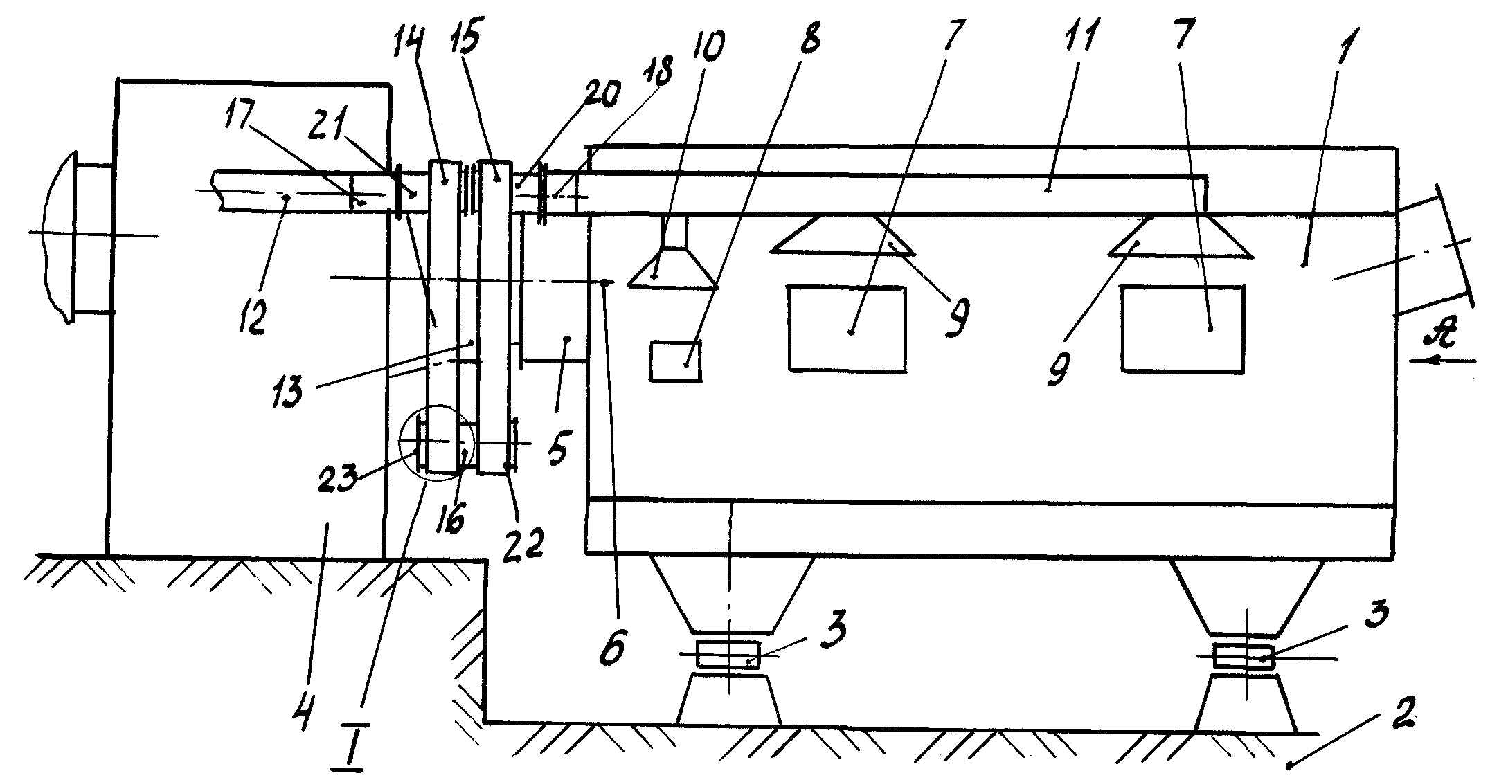
На фиг. 1 - изображен общий вид предлагаемого устройство для плавки металла.In FIG. 1 - shows a General view of the proposed device for melting metal.
На фиг. 2 - вид. А фиг. 1,In FIG. 2 - view. And FIG. 1,
На фиг.З - сечение узла 1 фиг. 1.In FIG. 3, a section through the assembly 1 of FIG. 1.
На фиг. 4 - сечение узла 1, выполненного в соответствии с п. 5 формулы изобретения.In FIG. 4 is a cross section of a node 1 made in accordance with paragraph 5 of the claims.
Предлагаемое устройство для плавки металлов содержит плавильную камеру 1 , установленную на опоре 2 с возможностью поворота на ней за счет тел качения 3. Отдельно от камеры 1 размещена пигаковая емкость 4 и соединенная с камерой газоходом 5 для удаления продуктов горения .Продольная ось газохода 5 совпадает с центром вращения 6 камеры l.Ha боковых стенках камеры 1 выполнены загрузочные окна 7 и 8 , а над ними жестко закреплены уловители 9 и 10, для сбора и удаления газов во время загрузки камеры 1. Все уловители 9 и 10 соединены газоотводящей магистралью И , которая тоже жесгко закреплена на боковой поверхности камеры 1. Магистраль 11 соединена с неподвижным отводом 12, установленным на пшаковой емкости 4 , причем их продольные оси преимущественно расположены на одной линии. Между камерой 1 и емкостью 4 выполнен зазор 13 , в котором размещен дополнительный щарнир. Шарнир состоит из двух полых жестких коробов 15 и 14, закрепленных одним концомThe proposed device for smelting metals contains a melting chamber 1 mounted on a support 2 with the possibility of rotation on it due to rolling elements 3. Separately from the chamber 1, a pigcake tank 4 is placed and connected to the chimney 5 to remove combustion products. The longitudinal axis of the chimney 5 coincides with the center of rotation 6 of the chamber l.Ha on the side walls of the chamber 1 made loading windows 7 and 8, and traps 9 and 10 are rigidly fixed above them to collect and remove gases during loading of the chamber 1. All traps 9 and 10 are connected to a gas outlet Yu, which is also rigidly fixed on the side surface of the chamber 1. The highway 11 is connected to a fixed branch 12 mounted on the pshakova tank 4, and their longitudinal axes are mainly located on the same line. Between the chamber 1 and the capacity 4, a gap 13 is made, in which an additional hinge is placed. The hinge consists of two hollow rigid boxes 15 and 14, fixed at one end
на тру 16, а другой конец соединен с фланцами 18 и 17 мапистрали 11 и отвода 12. В трубе 16 выполнены сквозные радиальные вырезы 19. На каждом коробе 15 и 14 в зонах соединения с трубой 16 и фланцами 18 и 17 закреплены фланцы 21 и 20 с боковыми заглушками 23 и 22. Каждый из фланцев 21 и 20 снабжен уплотнением 24, установленный между коробом 15 или 14 и заглушками 23 и 22.on the pipe 16, and the other end is connected to the flanges 18 and 17 of the pipe 11 and the outlet 12. In the pipe 16 there are made radial cut-outs 19. On each box 15 and 14 in the zones of connection with the pipe 16 and flanges 18 and 17 are fixed flanges 21 and 20 with side plugs 23 and 22. Each of the flanges 21 and 20 is provided with a seal 24 mounted between the duct 15 or 14 and the plugs 23 and 22.
Работа предлагаемого устройства осуществляется следующим образом. Внутрь плавильной камеры 1 через загрузочные окна 7 загружается шихта и под воздействием температуры осуществляют ее плавление. Одновременно образующиеся газы отводятся из нее через газоход 5 в шлаковую емкость 4. После плавления металла его выпускают из камеры и производят розлив металла , затем загружают новую шихту и процесс повторяется. В процессе загрузки металла через окна 7 и 8 вырывается наружу большое количество раскаленного газа, который улавливается уловителями 9 и 10. После улавливания газы черта магистраль 11 и короба 14и 15 попадают в отвод 12, а затем направляются на очистку и выбрасываются в атмосферу. Загрузка шихты в камеру 1 производится при ее вертикальном расположении и открытых окнах 7 и 8. После загрузки окна закрываются и производится плавка металла. После расплава для розлива металла вся камера наклоняется в сторону, противоположную относительно окон 7 и 8. В процессе поворота магистраль 11 вместе уловителями 9 и 10 наклоняются вместе с камерой 1. В результате этого короб 15 смещается относительно короба 14 и поворачивается на трубе 16 не увлекая за собой отвод 12, который вместе с емкостью 4 остается в неизменном положении. После окончания розлива металла камера 1 возвращается в исходное положение. При этом короба 14 и 15 возвращаются в исходное положение, поворачиваясь на трубе 16 и смещаясь в пространстве 13 между камерой 1 и емкостью 4The work of the proposed device is as follows. Inside the melting chamber 1, through the loading windows 7, a charge is loaded and, under the influence of temperature, it is melted. At the same time, the gases formed are removed from it through the gas duct 5 to the slag vessel 4. After melting the metal, it is released from the chamber and the metal is bottled, then a new charge is loaded and the process is repeated. In the process of loading metal through windows 7 and 8, a large amount of hot gas escapes out, which is trapped by traps 9 and 10. After collecting the gases, line 11 and ducts 14 and 15 fall into branch 12, and then are sent for cleaning and released into the atmosphere. The charge is loaded into the chamber 1 with its vertical arrangement and open windows 7 and 8. After loading, the windows are closed and metal is melted. After the melt for pouring metal, the entire chamber tilts in the direction opposite to the windows 7 and 8. During the rotation, the trunk 11 together with the catchers 9 and 10 are tilted together with the chamber 1. As a result, the duct 15 is shifted relative to the duct 14 and rotates on the pipe 16 without entrainment followed by a branch 12, which together with the tank 4 remains in the same position. After the pouring of metal chamber 1 returns to its original position. In this case, the boxes 14 and 15 return to their original position, turning on the pipe 16 and shifting in the space 13 between the camera 1 and the tank 4
Выполнение меж;цу плавильной камерой и шлаковой емкостью поворотного шарнира в виде двух металлических коробов и трубы позволяет разместить стационарно на поворотной печи систему отвода газов от загрузочных окон и получить надежное и долговечное подвижное соединение подвижной части с неподвижной частью отвода газов, имеющих высокую температуру. Кроме того, за счет выполнения подвижного шарнира металлическим снижается простой самой печи , увеличивается срок службы газохода и снижаются эксплуатационные затраты при использовании предложенного решения Вместе с тем отпадает необходимость введения дополнительных опор для размещения на них газоотводящих трактов, которые мешают при загрузке меггалла и занимают немалую площадь при их установки.The implementation of an inter-tsu melting chamber and a slag tank of a swivel joint in the form of two metal ducts and a pipe makes it possible to place the exhaust gas system from the loading windows stationary on the rotary kiln and to obtain a reliable and durable movable connection of the moving part to the fixed part of the exhaust gas having a high temperature. In addition, due to the metal hinge being made simple, the simple furnace itself is reduced, the gas duct life is increased, and operating costs are reduced when using the proposed solution. At the same time, there is no need to introduce additional supports to place gas exhaust ducts on them, which interfere with the loading of the gall and occupy a considerable area at their installation.
Использование предлагаемого технического решения позволяет увеличить стойкость шарнирного узла в 3-5 раз , упростить конструкцию газоходного тракта и снизить эксплуатационные затраты на 20-30% по сравнению с известными конструкциями плавильных печей , преимущественно для плавления цветных металлов.Using the proposed technical solution allows to increase the durability of the hinge assembly by 3-5 times, to simplify the design of the gas duct and reduce operating costs by 20-30% compared with the known designs of smelting furnaces, mainly for the melting of non-ferrous metals.
Инженер патентовед ////J// И.Д.Плеханов.Patent Engineer //// J // I.D. Plekhanov.
Claims (6)
Priority Applications (1)
| Application Number | Priority Date | Filing Date | Title |
|---|---|---|---|
| RU2000128282/20U RU17536U1 (en) | 2000-11-14 | 2000-11-14 | METAL FURNACE FURNACE |
Applications Claiming Priority (1)
| Application Number | Priority Date | Filing Date | Title |
|---|---|---|---|
| RU2000128282/20U RU17536U1 (en) | 2000-11-14 | 2000-11-14 | METAL FURNACE FURNACE |
Publications (1)
| Publication Number | Publication Date |
|---|---|
| RU17536U1 true RU17536U1 (en) | 2001-04-10 |
Family
ID=35870539
Family Applications (1)
| Application Number | Title | Priority Date | Filing Date |
|---|---|---|---|
| RU2000128282/20U RU17536U1 (en) | 2000-11-14 | 2000-11-14 | METAL FURNACE FURNACE |
Country Status (1)
| Country | Link |
|---|---|
| RU (1) | RU17536U1 (en) |
-
2000
- 2000-11-14 RU RU2000128282/20U patent/RU17536U1/en not_active IP Right Cessation
Similar Documents
| Publication | Publication Date | Title |
|---|---|---|
| RU2688067C1 (en) | Rotary melting furnace for processing non-ferrous metal wastes | |
| US4452434A (en) | Combination of a smelting-furnace pouring lip and casting gutter | |
| BRPI0414704B1 (en) | Procedure for collecting and treating reaction gases from a facility to produce molten metals as well as a corresponding facility to remove dust | |
| US5416792A (en) | Preheat system | |
| US6201826B1 (en) | Loading system for electric arc furnaces | |
| US3604376A (en) | Electric furnace ventilation and gas cooling cleaning system | |
| CN207849383U (en) | A kind of medical waste incineration furnace of environmental protection | |
| CN116557886B (en) | Shaft tube sealing device for preventing heat leakage of slag hole | |
| US4383678A (en) | Electric furnace scrap handling mill layout | |
| RU2732257C1 (en) | Rotary inclined furnace | |
| US3802679A (en) | Reverberatory furnace with air cooled inlet | |
| US3138648A (en) | Exhaust hood for oxygen furnaces | |
| US6163561A (en) | Cooled basket for steel plants | |
| RU27199U1 (en) | SLAG REMOVER | |
| CN100465565C (en) | Rotary furnace equipment for melting salt-free aluminum with screening and recovery of slag | |
| SU1447565A1 (en) | Arrangement for heating the lining of metallurgical container | |
| JP6949650B2 (en) | Incinerator ash melting treatment equipment | |
| US589769A (en) | Port end for metallurgical furnaces | |
| KR200382735Y1 (en) | collecting hood | |
| SU761818A1 (en) | DEVICE D ^ I REMOVE GAS FROM ARC 1 ’ | |
| CN211425086U (en) | Flue gas hood for improving preheating temperature of scrap steel | |
| GB2095804A (en) | Discharging molten metal | |
| JP2006057974A (en) | Method for removing dust from heated gas in waste pyrolysis equipment | |
| JPS6261876B2 (en) | ||
| JP7141109B2 (en) | HEAT AND ASH RECOVERY APPARATUS AND RECOVERY METHOD |
Legal Events
| Date | Code | Title | Description |
|---|---|---|---|
| ND1K | Extending utility model patent duration | ||
| MM1K | Utility model has become invalid (non-payment of fees) |
Effective date: 20081115 |