RU122949U1 - AIR SUSPENSION - Google Patents
AIR SUSPENSION Download PDFInfo
- Publication number
- RU122949U1 RU122949U1 RU2012134604/11U RU2012134604U RU122949U1 RU 122949 U1 RU122949 U1 RU 122949U1 RU 2012134604/11 U RU2012134604/11 U RU 2012134604/11U RU 2012134604 U RU2012134604 U RU 2012134604U RU 122949 U1 RU122949 U1 RU 122949U1
- Authority
- RU
- Russia
- Prior art keywords
- traverse
- air suspension
- terminals
- continuous
- semi
- Prior art date
Links
Abstract
1. Пневматическая подвеска, содержащая, по меньшей мере, одну неразрезную ось, V-образную реактивную штангу, нижние продольные реактивные штанги, траверсы, упругие элементы, установленные на траверсе по обеим сторонам неразрезной оси, стабилизатор бокового крена и амортизаторы, отличающаяся тем, что крепление траверсы к неразрезной оси выполнено с помощью разъемного клеммового соединения, при этом рабочие поверхности полуклемм выполнены с уклоном.2. Пневматическая подвеска по п.1, отличающаяся тем, что одна из полуклемм выполнена с проушиной для крепления амортизатора.1. Pneumatic suspension containing at least one continuous axle, V-shaped reaction rod, lower longitudinal reaction rods, traverses, elastic elements installed on the traverse on both sides of the continuous axis, side roll stabilizer and shock absorbers, characterized in that the traverse is fastened to the continuous axle using a detachable terminal connection, while the working surfaces of the semi-terminals are made with a slope. 2. Air suspension according to claim 1, characterized in that one of the semi-terminals is made with an eyelet for attaching the shock absorber.
Description
Полезная модель относится к автомобильной промышленности, в частности, к подвескам транспортных средств с пневматическим подрессориванием с двумя и более осями.The utility model relates to the automotive industry, in particular, to the suspension of vehicles with pneumatic suspension with two or more axles.
Известна подвеска с траверсой, содержащая V-образную реактивную штангу, нижние реактивные продольные штанги, упругие элементы, установленные на траверсе по обеим сторонам неразрезной оси и стабилизатор бокового крена, крепление траверсы к оси выполняется при помощи разъемного и неразъемного соединений, а именно сварного и с использованием стремянок или шпилек (см. патент № RU 114000, МПК (2006.01) B60G 21/04, 2012 г.).Known suspension with a traverse containing a V-shaped reactive rod, lower reactive longitudinal rods, elastic elements mounted on the traverse on both sides of the continuous axis and the side roll stabilizer, the beam is mounted to the axis using detachable and one-piece joints, namely, welded and with the use of ladders or hairpins (see patent No. RU 114000, IPC (2006.01) B60G 21/04, 2012).
Недостатком известной конструкции пневматической подвески является высокая трудоемкость сборки, обусловленная использованием неразъемного и разъемного соединений, при креплении траверсы к оси.A disadvantage of the known design of the air suspension is the high complexity of the assembly, due to the use of one-piece and detachable joints, when attaching the yoke to the axis.
Была поставлена задача, снизить трудоемкость сборки пневматической подвески, а также обеспечить ее ремонтопригодность.The task was set to reduce the complexity of the assembly of the air suspension, as well as to ensure its maintainability.
Поставленная задача решается тем, что в пневматической подвеске, содержащей, по меньшей мере, одну неразрезную ось, V-образную реактивную штангу, нижние продольные реактивные штанги, траверсы, упругие элементы, установленные на траверсе по обеим сторонам неразрезной оси, стабилизатор бокового крена и амортизаторы, крепление траверсы к неразрезной оси выполнено с помощью разъемного клеммового соединения, при этом рабочие поверхности полуклемм выполнены с уклоном.The problem is solved in that in a pneumatic suspension containing at least one continuous axis, a V-shaped reaction rod, lower longitudinal reaction rods, traverses, elastic elements mounted on the traverse on both sides of the continuous axis, side roll stabilizer and shock absorbers , the traverse is fixed to the continuous axis using a detachable terminal connection, while the working surfaces of the semi-terminals are made with a slope.
Одна из полуклемм выполнена с проушиной для крепления амортизатора.One of the terminals is made with an eye for attaching a shock absorber.
Новым в заявляемой пневматической подвеске является крепление траверсы к неразрезной оси с помощью разъемного клеммового соединения, выполнение рабочих поверхностей полуклемм с уклоном, и выполнение одной из полуклемм с проушиной для крепления амортизатора.New in the inventive air suspension is the mounting of the traverse to the continuous axis using a detachable terminal connection, the execution of the working surfaces of the terminals with a slope, and the implementation of one of the terminals with an eye for attaching a shock absorber.
Крепление траверсы к неразрезной оси с помощью разъемного клеммового соединения, выполнение рабочих поверхностей полуклемм с уклоном и одной из них с проушиной для крепления амортизатора -позволяет снизить трудоемкость сборки пневматической подвески, а также обеспечить ее ремонтопригодность за счет простоты монтажа клеммового соединения.Attaching the traverse to the continuous axis using a detachable terminal connection, the execution of the working surfaces of the semi-terminals with a slope and one of them with an eye for attaching the shock absorber allows to reduce the laboriousness of the assembly of the air suspension, as well as to ensure its maintainability due to the ease of installation of the terminal connection.
Кроме того, вышеперечисленные признаки позволяют получить дополнительный технический результат, заключающийся в унифицикации конструкции траверсы, позволяющей использовать ее в автомобилях с двумя и более осями.In addition, the above features allow you to get an additional technical result, which consists in the unification of the design of the beam, allowing its use in cars with two or more axles.
Анализ известных технических решений, проведенный по научно-технической и патентной документации, показал, что совокупность существенных признаков заявляемого технического решения не известна из уровня техники, следовательно, оно соответствует условию патентоспособности полезной модели - «новизна».An analysis of the known technical solutions, carried out on the basis of scientific, technical and patent documentation, showed that the set of essential features of the claimed technical solution is not known from the prior art, therefore, it meets the patentability condition of the utility model - “novelty”.
Заявляемая полезная модель иллюстрируется чертежами:The inventive utility model is illustrated by drawings:
фиг.1 - пневматическая подвеска, вид спереди;figure 1 - air suspension, front view;
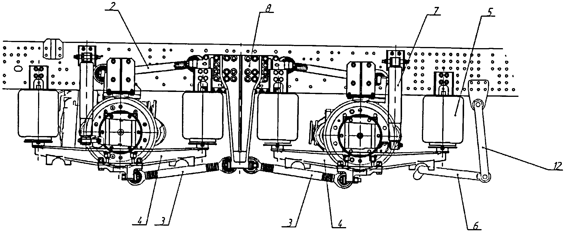
фиг.2 - пневматическая подвеска, вид сверху;figure 2 - air suspension, top view;
фиг.3 - пневматическая подвеска, разрез А-А, крепление траверсы к неразрезной оси.figure 3 - air suspension, section aa, the mounting of the beam to the continuous axis.
Пневматическая подвеска содержит неразрезные оси 1, V-образные реактивные штанги 2, нижние продольные реактивные штанги 3, траверсы 4, упругие элементы 5, стабилизатор бокового крена 6 и амортизаторы 7.The air suspension contains continuous axes 1, V-shaped reactive rods 2, lower longitudinal reactive rods 3, traverses 4, elastic elements 5, side-roll stabilizer 6 and shock absorbers 7.
V-образная реактивная штанга 2 центральной частью посредством кронштейна крепится к неразрезной оси 1, а свободными концами к кронштейнам 8 рамы транспортного средства.The V-shaped reaction rod 2, the central part by means of a bracket attached to the continuous axis 1, and the free ends to the brackets 8 of the vehicle frame.
К неразрезной оси 1, с обоих сторон транспортного средства, с помощью разъемного клеммового соединения крепятся траверсы 4. Рабочие поверхности полуклемм 9, 10 выполнены с уклоном. Уклон полуклемм обеспечивает проворачивание неразрезной оси 1 на необходимый угол, за счет чего обеспечивается унификация конструкции траверсы. Полуклемма 9 выполнена с проушиной 11 для крепления амортизатора 7. Другим концом амортизатор 7 крепится к раме транспортного средства посредством кронштейна.Traverse 4 is attached to the continuous axis 1, on both sides of the vehicle, using a detachable terminal connection. The working surfaces of the semi-terminals 9, 10 are made with a slope. The bias of the half-terminals ensures the rotation of the continuous axis 1 by the required angle, due to which the unification of the crosshead design is ensured. The terminal 9 is made with an eye 11 for attaching a shock absorber 7. At the other end, the shock absorber 7 is attached to the vehicle frame by means of an arm.
Нижние продольные реактивные штанги 3 расположены с двух сторон вдоль продольной оси транспортного средства и шарнирно закреплены к кронштейнам 8 рамы транспортного средства и траверсам 4.The lower longitudinal reaction rods 3 are located on two sides along the longitudinal axis of the vehicle and are pivotally attached to the brackets 8 of the vehicle frame and traverses 4.
На концах траверсы 4 закреплены упругие элементы 5, выполненные в виде пневморессор с элементами для крепления к раме транспортного средства.At the ends of the beam 4 fixed elastic elements 5, made in the form of air springs with elements for attachment to the frame of the vehicle.
Стабилизатор бокового крена 6 выполнен П-образным. Стабилизатор 6 центральной частью крепится к траверсам 4, а своими концами через стойку 12 к раме транспортного средства.The stabilizer side roll 6 is made U-shaped. The stabilizer 6 central part is attached to the traverse 4, and its ends through the rack 12 to the frame of the vehicle.
Заявляемая пневматическая подвеска работает следующим образом.The inventive air suspension operates as follows.
При воздействии нагрузки со стороны дороги на неразрезную ось 1 транспортного средства она передается через полуклеммы 9, 10 к траверсам 4, далее через траверсы 4 на пневморессоры 5 и далее на раму транспортного средства. Благодаря выполнения рабочих поверхностей полуклемм 9, 10 с уклоном, при работе неразрезная ось 1 транспортного средства поворачивается на необходимый угол, тем самым снижая нагрузки в подшипники карданных соединений с сохранением низких вибраций.When the load from the side of the road on the continuous axis 1 of the vehicle, it is transmitted through the terminal 9, 10 to the traverse 4, then through the traverse 4 to the air springs 5 and then to the frame of the vehicle. Due to the execution of the working surfaces of the semi-terminals 9, 10 with a slope, during operation, the continuous axle 1 of the vehicle rotates by the required angle, thereby reducing the load on the bearings of the universal joints with low vibrations.
Заявляемая конструкция пневматической подвески позволяет снизить трудоемкость сборки пневматической подвески и обеспечить ее ремонтопригодность. Таким образом, технический результат достигнут.The inventive design of the air suspension allows you to reduce the complexity of the Assembly of the air suspension and ensure its maintainability. Thus, the technical result is achieved.
Заявляемая пневматическая подвеска может быть изготовлена на стандартном оборудовании из известных материалов с использованием современных технологий.The inventive air suspension can be made on standard equipment from well-known materials using modern technology.
Claims (2)
Priority Applications (1)
| Application Number | Priority Date | Filing Date | Title |
|---|---|---|---|
| RU2012134604/11U RU122949U1 (en) | 2012-08-13 | 2012-08-13 | AIR SUSPENSION |
Applications Claiming Priority (1)
| Application Number | Priority Date | Filing Date | Title |
|---|---|---|---|
| RU2012134604/11U RU122949U1 (en) | 2012-08-13 | 2012-08-13 | AIR SUSPENSION |
Publications (1)
| Publication Number | Publication Date |
|---|---|
| RU122949U1 true RU122949U1 (en) | 2012-12-20 |
Family
ID=49256815
Family Applications (1)
| Application Number | Title | Priority Date | Filing Date |
|---|---|---|---|
| RU2012134604/11U RU122949U1 (en) | 2012-08-13 | 2012-08-13 | AIR SUSPENSION |
Country Status (1)
| Country | Link |
|---|---|
| RU (1) | RU122949U1 (en) |
Cited By (5)
| Publication number | Priority date | Publication date | Assignee | Title |
|---|---|---|---|---|
| RU172491U1 (en) * | 2016-09-01 | 2017-07-11 | Публичное акционерное общество "КАМАЗ" | Vehicle Rear Air Suspension |
| RU172940U1 (en) * | 2016-10-26 | 2017-08-01 | Общество С Ограниченной Ответственностью "Научно-Производственное Объединение "Ростар" | AIR SUSPENSION |
| RU181478U1 (en) * | 2017-12-20 | 2018-07-16 | Публичное акционерное общество "КАМАЗ" | REAR PNEUMATIC SUSPENSION OF A VEHICLE |
| RU2713263C2 (en) * | 2015-07-23 | 2020-02-04 | Ивеко Магирус Аг | Pneumatic axle suspension for rear axle of vehicle |
| RU221800U1 (en) * | 2023-09-22 | 2023-11-23 | Общество С Ограниченной Ответственностью "Научно-Производственное Объединение "Ростар" | VEHICLE SUSPENSION CROSS BAR |
-
2012
- 2012-08-13 RU RU2012134604/11U patent/RU122949U1/en active
Cited By (5)
| Publication number | Priority date | Publication date | Assignee | Title |
|---|---|---|---|---|
| RU2713263C2 (en) * | 2015-07-23 | 2020-02-04 | Ивеко Магирус Аг | Pneumatic axle suspension for rear axle of vehicle |
| RU172491U1 (en) * | 2016-09-01 | 2017-07-11 | Публичное акционерное общество "КАМАЗ" | Vehicle Rear Air Suspension |
| RU172940U1 (en) * | 2016-10-26 | 2017-08-01 | Общество С Ограниченной Ответственностью "Научно-Производственное Объединение "Ростар" | AIR SUSPENSION |
| RU181478U1 (en) * | 2017-12-20 | 2018-07-16 | Публичное акционерное общество "КАМАЗ" | REAR PNEUMATIC SUSPENSION OF A VEHICLE |
| RU221800U1 (en) * | 2023-09-22 | 2023-11-23 | Общество С Ограниченной Ответственностью "Научно-Производственное Объединение "Ростар" | VEHICLE SUSPENSION CROSS BAR |
Similar Documents
| Publication | Publication Date | Title |
|---|---|---|
| RU122949U1 (en) | AIR SUSPENSION | |
| RU158670U1 (en) | VEHICLE SUSPENSION | |
| RU186871U1 (en) | PNEUMATIC SUSPENSION OF A VEHICLE | |
| CN105501017A (en) | Guide-out single-bearing-point independent suspension | |
| RU109437U1 (en) | SUSPENSION VEHICLE WITH STABILIZER | |
| RU169242U1 (en) | FRONT INDEPENDENT SUSPENSION ASSEMBLY ASSEMBLY | |
| CN206968333U (en) | A kind of automobile using front air suspension structure | |
| CN102218981A (en) | Semi-independent suspension structure for torsion beam of automobile | |
| RU172940U1 (en) | AIR SUSPENSION | |
| CN203984147U (en) | A kind of blower motor | |
| RU172491U1 (en) | Vehicle Rear Air Suspension | |
| RU114000U1 (en) | TRAVEL SUSPENSION | |
| CN105501013A (en) | Formula student China (FSC) racing car lever pull arm type double cross arm independent suspension | |
| CN201849279U (en) | Torsion bar stabilizing device for torsion beam of automobile | |
| RU118256U1 (en) | AXLE SUSPENSION | |
| CN203198669U (en) | Automobile torsion beam semi-independent back suspension frame | |
| CN204367797U (en) | The medium bus front air suspension of X-shaped guide arm structure | |
| RU165637U1 (en) | PNEUMATIC SUSPENSION OF A VEHICLE | |
| CN202046173U (en) | Semi-independent-suspension structure for torsion beam of vehicle | |
| CN203211036U (en) | Triangular arm structure of automobile | |
| RU113203U1 (en) | SUSPENSION FOR CONTINUOUS VEHICLE BRIDGES | |
| CN202186439U (en) | Front suspension device for cab | |
| RU111482U1 (en) | STRIPED VEHICLE SUSPENSION (OPTIONS) | |
| CN206510707U (en) | A kind of beach buggy and its rear suspension | |
| CN203198655U (en) | Double-wishbone type suspension frame |