KR940010375B1 - Gun with pivoting barrel and cocking mechanism - Google Patents
Gun with pivoting barrel and cocking mechanism Download PDFInfo
- Publication number
- KR940010375B1 KR940010375B1 KR1019870001690A KR870001690A KR940010375B1 KR 940010375 B1 KR940010375 B1 KR 940010375B1 KR 1019870001690 A KR1019870001690 A KR 1019870001690A KR 870001690 A KR870001690 A KR 870001690A KR 940010375 B1 KR940010375 B1 KR 940010375B1
- Authority
- KR
- South Korea
- Prior art keywords
- barrel
- lever
- gun
- frame
- hammer
- Prior art date
Links
Images


Classifications
-
- F—MECHANICAL ENGINEERING; LIGHTING; HEATING; WEAPONS; BLASTING
- F41—WEAPONS
- F41B—WEAPONS FOR PROJECTING MISSILES WITHOUT USE OF EXPLOSIVE OR COMBUSTIBLE PROPELLANT CHARGE; WEAPONS NOT OTHERWISE PROVIDED FOR
- F41B11/00—Compressed-gas guns, e.g. air guns; Steam guns
-
- F—MECHANICAL ENGINEERING; LIGHTING; HEATING; WEAPONS; BLASTING
- F41—WEAPONS
- F41B—WEAPONS FOR PROJECTING MISSILES WITHOUT USE OF EXPLOSIVE OR COMBUSTIBLE PROPELLANT CHARGE; WEAPONS NOT OTHERWISE PROVIDED FOR
- F41B11/00—Compressed-gas guns, e.g. air guns; Steam guns
- F41B11/60—Compressed-gas guns, e.g. air guns; Steam guns characterised by the supply of compressed gas
- F41B11/64—Compressed-gas guns, e.g. air guns; Steam guns characterised by the supply of compressed gas having a piston effecting a compressor stroke during the firing of each shot
- F41B11/642—Compressed-gas guns, e.g. air guns; Steam guns characterised by the supply of compressed gas having a piston effecting a compressor stroke during the firing of each shot the piston being spring operated
- F41B11/646—Arrangements for putting the spring under tension
- F41B11/647—Arrangements for putting the spring under tension by a rocker lever
- F41B11/648—Arrangements for putting the spring under tension by a rocker lever in breakdown air guns
-
- F—MECHANICAL ENGINEERING; LIGHTING; HEATING; WEAPONS; BLASTING
- F41—WEAPONS
- F41A—FUNCTIONAL FEATURES OR DETAILS COMMON TO BOTH SMALLARMS AND ORDNANCE, e.g. CANNONS; MOUNTINGS FOR SMALLARMS OR ORDNANCE
- F41A3/00—Breech mechanisms, e.g. locks
- F41A3/58—Breakdown breech mechanisms, e.g. for shotguns
-
- F—MECHANICAL ENGINEERING; LIGHTING; HEATING; WEAPONS; BLASTING
- F41—WEAPONS
- F41B—WEAPONS FOR PROJECTING MISSILES WITHOUT USE OF EXPLOSIVE OR COMBUSTIBLE PROPELLANT CHARGE; WEAPONS NOT OTHERWISE PROVIDED FOR
- F41B11/00—Compressed-gas guns, e.g. air guns; Steam guns
- F41B11/60—Compressed-gas guns, e.g. air guns; Steam guns characterised by the supply of compressed gas
- F41B11/62—Compressed-gas guns, e.g. air guns; Steam guns characterised by the supply of compressed gas with pressure supplied by a gas cartridge
-
- F—MECHANICAL ENGINEERING; LIGHTING; HEATING; WEAPONS; BLASTING
- F41—WEAPONS
- F41B—WEAPONS FOR PROJECTING MISSILES WITHOUT USE OF EXPLOSIVE OR COMBUSTIBLE PROPELLANT CHARGE; WEAPONS NOT OTHERWISE PROVIDED FOR
- F41B11/00—Compressed-gas guns, e.g. air guns; Steam guns
- F41B11/70—Details not provided for in F41B11/50 or F41B11/60
-
- F—MECHANICAL ENGINEERING; LIGHTING; HEATING; WEAPONS; BLASTING
- F41—WEAPONS
- F41C—SMALLARMS, e.g. PISTOLS, RIFLES; ACCESSORIES THEREFOR
- F41C7/00—Shoulder-fired smallarms, e.g. rifles, carbines, shotguns
- F41C7/11—Breakdown shotguns or rifles
Abstract
Description
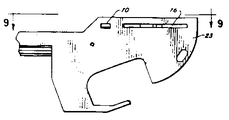
제 1 도는 본 발명에 따른 총이 장전 위치에 있을 때 일부 절개측면도.1 is a partial cutaway side view when the gun according to the invention is in the reload position.
제 2 도는 제 1 도의 평면도.2 is a plan view of FIG.
제 3 도는 발사위치에서 제 1 도와 유사한 측면도.3 is a side view similar to the 1st degree in a launch position.
제 4 도는 제 3 도의 평면도.4 is a plan view of FIG.
제 5 도는 제 3 도의 선 5-5에 따른 단면도.5 is a sectional view along line 5-5 of FIG.
제 6 도는 제 3 도의 선 6-6에 따른 단면도.6 is a sectional view along line 6-6 of FIG.
제 7 도는 프레임이 덮개판이 없는 총프레임의 부분 우측면도.7 is a partial right side view of the total frame with no cover plate.
제 8 도는 총프레임의 부분좌측면도.8 is a partial left side view of the total frame.
제 9 도는 제 8 도의 선 9-9에 따른 부분평면도.9 is a partial plan view along line 9-9 of FIG.
제 10 도는 제 7 도의 선 10-10에 따른 단면도.10 is a sectional view along line 10-10 of FIG.
제 11 도는 제 7 도의 선 11-11에 따른 단면도.11 is a sectional view along line 11-11 of FIG.
제 12 도는 제 7 도의 선 12-12에 따른 단면도.12 is a sectional view along line 12-12 of FIG.
제 13 도는 프레임덮개판이 제거된 총프레임과 총열조립체의 측면도.13 is a side view of the gun frame and barrel assembly with the frame cover plate removed.
제 14 도는 제 13 도의 총프레임과 총열의 평면도.14 is a plan view of the barrel and barrel of FIG. 13;
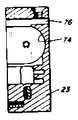
제 15 도는 햄머의 단면도.Fig. 15 is a cross-sectional view of the hammer.
제 16 도는 제 15 도의 선 16-16에 따른 햄머의 단면도.16 is a cross-sectional view of the hammer along line 16-16 of FIG.
제 17 도는 레버패드의 평면도.17 is a plan view of the lever pad.
제 18 도는 V블록의 평면도.18 is a plan view of the V block.
제 19 도는 제 18 도의 선 19-19에 따른 V-블록의 측면도.19 is a side view of the V-block according to line 19-19 of FIG. 18;
* 도면의 주요부분에 대한 부호의 설명* Explanation of symbols for main parts of the drawings
23 : 프레임 25 : 총열23: frame 25: barrel
26 : 총구 27 : 개머리판쪽 끝26 muzzle 27 end of the butt
28 : 총구 끝 30 : 가스통28: muzzle end 30: gas cylinder
31 : 밸브조립체 33 : 시어31: valve assembly 33: shear
34 : 햄머 36 : 밸브스템34: hammer 36: valve stem
50 : 가늠쇠 39 :덮개판50: 39: cover plate
58 : 싱크 56 : V-블록58: sink 56: V-block
64 : 지지핑거부 61 : 피봇레버64: support finger 61: pivot lever
73 : 가스켓 65 : 레버패드73: gasket 65: lever pad
77 : 격발아암77: triggered arm
본 발명은 총, 더욱 상세하게는 회전하는 총열과 총을 격발하기 위해 총열을 발사위치로 유지하는 격발장치를 장비한 총에 관한 것이다.The present invention relates to a gun, more particularly a rotating barrel and a gun equipped with a trigger for holding the barrel in the firing position for triggering the gun.
공기총에는 자주 총열이 회전하도록 결합설계된다. 이것은 탄약구멍을 점검하고, 구멍의 청소를 쉽게하며, 총구속으로 탄알을 장전시키며, 정확도에 나쁜 영향을 주는 총구속에 횡구멍이 없는 특징이 있다. 그러나, 총열이 설계오차 또는 마모로 인해 발사후 정확한 위치로 뒤돌아 가지않으면 총의 정확도가 떨어질 것이다. 더욱이, 발사 위치로 총열이 유지될 때 총열의 움직임이 없어야 최적의 정확도로 발사시 일어나는 힘을 충분히 지탱할 수 있는 것이다. 총열에서 갑작스런 충격으로 피봇 및 잠김 장치내에 조기 마모가 일어나서 정확도가 떨어지고 총열이 잠김 위치에 있을 때 변위가 생긴다.Air guns are frequently designed to rotate the barrel. It is characterized by a check of ammunition holes, easy cleaning of the holes, loading bullets into the gun barrel, and no cross hole in the gun barrel which adversely affects accuracy. However, if the barrel does not return to its correct position after firing due to design errors or wear, the gun will lose accuracy. Moreover, when the barrel is held in the firing position, there should be no movement of the barrel to fully support the force generated during firing with optimum accuracy. Sudden shock in the barrel causes premature wear in the pivot and locking device, resulting in less accuracy and displacement when the barrel is in the locked position.
본 발명는 최적의 정확도, 조작의 용이성, 구조의 단순성을 특징으로 하는 피봇팅 총열과 격발장치를 제시한다. 총에 레버가 선회하도록 설치되어 총열이 발사위치로 되게 한다. 총열이 풀리도록 레버가 선회할 때 장전위치로 총열은 자동적인 선회를 하고, 레버는 햄머를 치게 된다. 발사위치로 총열을 다시 선회할 때는, 레버가 잠김 위치로 되돌아 오게된다. 총에 있는 블록에 의해 총열의 발사 위치는 조절되어지고 조정 스크루에 의해 레버의 잠김력은 조절되어 진다. 피봇시 놀음(Play)을 없애기 위하여 총열은 스프링하중을 받는다. 그리고 밀봉 가스킷(gasket)은 발사 위치에서 총열의 개머리판끝을 밀봉시킨다. 총의 프레임에 의해 부당한 충격을 총열의 측면이 방지한다.The present invention proposes a pivoting barrel and percussion device characterized by optimum accuracy, ease of operation, and simplicity of structure. The lever is pivoted on the gun so that the barrel is in the firing position. When the lever turns to release the barrel, the barrel turns automatically to the loaded position, and the lever strikes the hammer. When turning the barrel back to the firing position, the lever returns to the locked position. The firing position of the barrel is controlled by the block in the gun and the locking force of the lever is adjusted by the adjusting screw. To eliminate Play during pivoting, the barrel is loaded with a spring load. And a sealing gasket seals the barrel end of the barrel in the firing position. The side of the barrel prevents an improper shock by the frame of the gun.
제 1-4 도에서 총(22)은 프레임(23), 손잡이(24), 프레임에 회전하도록 설치된 총열(25)로 구성되어 있다. 총구(26), 개머리판쪽(27) 그리고 총구끝(28)으로 형성되어 있는 총열은 제 1 도의 정전위치와 제 3 도의 발사위치 사이로 선회한다.In FIGS. 1-4, the
예시된 특수총은 가스총으로 압축가수(co2)를 저장하는 가스통(30)과 총이 발사될 때 까지 충전된 압축 가스를 저장하기 위한 밸브조립체(31)를 구성하고 있다. 밸브조립체(31)내 충전압축가스(co2)는 시어(sear)(33)를 아래방향으로 회전시키는 방아쇠(32)를 당김으로 방출된다. 햄머(34)가 풀려서 햄머스프링(35)에 의해 좌측으로 구동되어 진다. 햄머가 밸브스템(36)의 좌측끝을 때릴때 밸브스템의 우측끝은 밸브밀봉부재(37)로부터 떨어져서 밸브스프링(38)의 바이어스에 대하여 좌측으로 움직인다. 밸브조립체내 압축가스는 총열의 개머리판쪽 끝으로 흘러 탄알이 총열을 벗어나도록 추진한다. 밸브조립체, 방아쇠, 시어등은 기술상 알려져 있는 것이며 여기서는 설명할 필요가 없다. 덮개판(39)은 발사장치를 보호하기 위해 스크류에 의해 프레임의 우측에 부착되어 있다.The illustrated special gun comprises a
프레임(23)은 밸브조립체(31) 앞쪽으로 뻗어있는 체널형 총열지지부(40)를 형성하고 있다. 총열지지부(40)는 한쌍의 측벽(41, 42)과 저벽(43)을 구성한다. 제 6 도를 참고하면, 총열(25)은 측벽(41, 42)를 프레임에 고정시키는 한쌍의 스크루(44, 45)에 의해 총구 끝에 접하게 고정되어 선회한다. 스크루(44, 45)는 총열의 측면에 있는 반대편 구멍으로 뻗어있는 피봇핀(46, 47)에서 끝이 난다. 네 개의 접식형 스프링와셔(48)는 피봇핀(46)에 설치되고 총열을 피봇핀(47)이 고정시킨다. 총열에 30파운드 힘을 스프링와셔가 지탱하며 총열의 측면 놀음을 제거해 준다.The
프레임의 총열부의 측벽 전방끝은 총구의 위에서 위쪽을 뻗어있어 가늠쇠설치러그(49)(14 도에서 보이지 않음)를 제공한다. 가늠쇠(50)는 스크루(51)에 의해 러그(49)에 설치된다. 가늠쇠핀(52)은 가늠쇠로부터 윗쪽으로 뻗어있다.The side wall front end of the barrel of the frame extends upwards above the muzzle to provide a latch installation lug 49 (not shown in 14 degrees). The
코일스프링(54)은 가늠쇠내에 있는 반대편구멍(55)에 위치하고 피봇핀(46, 47)의 총열 전방에 맞물려 있다. 스프링(54)은 50파운드의 힘을 받는 총열을 적재하여 총열과 피봇된 사이 수직놀음을 제거한다. 스프링(54)은 또한 제 1 도의 장전위치로 피봇하도록 총열이 기울어져 있다.The coil spring 54 is located in the
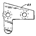
총열의 발사위치는 V-블록(56)에 의해 고정된다. 블록은 스쿠류(57)에 의해 (제 5 도)프레임의 측벽(41, 42)사이에 설치된다. 그런데 스크루는 V-블록내 한쌍의 싱크(sing)(58)(제 19 도)속으로 측벽을 지나 뻗어있다. V-블록은 일반적으로 내각이 90인 V형 홈을 형성하는 벌려진 측벽(59)으로 형성되어 있다. 총열이 발사위치에 있을 때 V-블록의 측벽(59)은 총열과 맞물려 있고 총열을 위한 고정위치를 제공한다. V-블록은 소결철로 형성하는 것이 유리하다. 총열은 피보팅레버(61)에 의해 발사위치로 된다(제 2, 4 도). 레버는 스크루(62)에 의해 프레임(23)에 설치되어 선회하고 제 4 도에 도시된 총열 잠김위치와 제 2 도에 도시된 풀림 위치사이에서 선회한다. 레버의 바깥쪽끝(63)은 우둘투둘하여 레버를 용이하게 잡도록 한다.The firing position of the barrel is fixed by the V-
레버(61)상의 지지핑거(finger)부(64)는 총열을 V-블록에 대하여 지지되도록 총열의 상단부와 맞물려 있다. 레버패드(pad)(65)(제 5, 16 도)는 한쌍의 스크루(66)에 의해 레버에 부착되어 있다. 그리고 총열과 맞물려 있는 패드의 제1끝은 레버가 잠김 위치로 움직일 때 총열이 아래쪽으로 왕복이동하도록 (67)에서 (제 5 도)비스듬하게 되어 있다. 레버페드는 마찰저항이 있고 아세탈(acetal)이나 우레탄(urethane)등 마찰계수가 작은 물질로 되어 있다. 하나의 특수한 예로 검은 델린(Delrin)(10)이 사용된다. 레버(61)는 또한 프레임에 있는 슬롯(70)속으로 뻗어있는 조정핑거부(69)를 형성하고 있다. 조정스크루(71)(제 1-3 도)는 조정핑거부(69)와 V-블록(56)에 대한 레버의 수직위치를 조정하기 위하여 슬롯(70)의 아래쪽으로 뻗어있다.The
총열이 발사위치에 있을 때, 총열의 개머리판쪽 끝은 밀봉되어 져 환형밀봉부재(73)(제 1, 3 도)에 의해 맞물려 있다. 밀봉 가스킷은 밸브조립체 앞쪽 끝에 의해 형성된 실린더형 홈에 설치되어 있고 밸브조립체와 총열사이에 가스가 새지않는 밀봉부재를 제공하여 총이 발사될 때 공기의 누설을 방지한다. 밸브조립체는 일반적으로 프레임(23)과 프레임덮개판(39)에 의해 형성된 실린더실(74)안에 설치되어 있다.When the barrel is in the firing position, the butt end of the barrel is sealed and engaged by the annular sealing member 73 (first and third degrees). The sealing gasket is installed in a cylindrical groove formed by the front end of the valve assembly and provides a gastight sealing member between the valve assembly and the barrel to prevent leakage of air when the gun is fired. The valve assembly is generally provided in the
레버(61)의 후미 끝은 프레임(23)내에 있는 슬롯(76)안에 위치한다(제 7, 8, 12 도). 격발아암(77)(제 2, 4 도)은 레버의 후미끝단부에서부터 피봇스크루(62)에 떨어져서 뻗어있다. 격박아암(77)은 햄머(34)에 부착되어 있는 핀조립체(78)과 함께 맞물려 있다.The rear end of the
제 15, 16 도를 참고하면, 햄머(34)는 일반적으로 실린더형이고 실린더측벽(79)와 후미벽(80)을 형성하고 있다. 햄머는 밸브스템이 뻗어있는 후미벽(80)내 계부(81)에 의해 밸브스템(36)에 장치되어 왕복한다. 햄머는 프레임의 홈(74)내에 설치된 햄머튜브(82)에 의해 감싸져서 왕복한다.Referring to FIGS. 15 and 16, the
핀조립체(78)는 한쌍의 롤러(83, 84)와 회전가능하게 롤러에 설치된 핀(85)으로 구성된다. 핀조립체(78)은 햄머튜브(82)내에 있는 슬롯(86)을 지나 레버(61)가 설치되어 있는 슬롯(76)으로 햄머 왕복방향에 수직으로 뻗어있다. 레버가 제 4 도의 잠김위치에서 제 2 도의 풀림위치로 움직였을 때 격박아암은 윗쪽롤러(83)과 맞물리고 햄머를 앞쪽으로 움직인다. 햄머는 시어(33)에 의해 앞쪽 또는 격박 위치로 가게하고 레버가 잠김 위치로 되돌아 갈 때 햄머는 격발되게 할 것이다.The
후미가늠자(88)는 프레임윗쪽에 있는 스프루구멍(89)속으로 뻗어있는 스크루에 의해 프레임상에 설치되어 진다.The tail scale 88 is mounted on the frame by a screw extending into the
피보팅총열과 격박장치의 조작은 상기 기술에서 분명해졌다. 레버(61)가 풀림위치로 움직일 때 총구끝에서 스프링(54)이 제 1 도에서 보여주는 장전위치로 총열을 선회시킨다. 총열의 구멍은 원한다면 청소할 수 있고 탄알은 총열의 개머리판쪽 끝에서 장전되어 진다. 레버가 풀림위치로 움직임으로 또한 햄머(34)를 격발한다.Manipulation of the pivoting barrel and the arrester was evident in the art. When the
총열이 장전된 후, 그것이 발사위치로 되돌아가서 레버(61)은 잠김 위치로 선회한다. 지지핑거부(64)가 총열과 맞물렸을 때 총열은 V-블록(56)에 강제된다. 밸브조립체(31)에 대한 총열의 위치는 고정된다. 지지력은 조정스크루(71)에 의해 주기적으로 조절될 수 있다. 총열은 그것에 의해 발사되기 위하여 발사 위치로 되고 발사되는 동안 움직이지 않는다.After the barrel is loaded, it returns to the firing position and the
프레임의 총열이 있는 부분의 측벽(41, 42)은 급작스런 충격에 대하여 총열을 보호한다. 접시형 스프링 와셔(48)와 코일스프링(54)은 어떠한 방향에서든지 총열의 놀음을 방지한다.
앞 설명서에서 본 발명은 예시적인 목적으로 상세히 기술되어 졌지만, 여기에 주어진 상세한 설명은 본 발명의 범위를 벗어나지 않게 본 분야에 기술이 있는 사람에 의해 상당히 변화가 있을 것이다.While the invention has been described in detail in the foregoing description for purposes of illustration, the description given herein will vary significantly by those skilled in the art without departing from the scope of the invention.
Claims (16)
Applications Claiming Priority (2)
| Application Number | Priority Date | Filing Date | Title |
|---|---|---|---|
| US917,015 | 1986-10-09 | ||
| US06/917,015 US4774929A (en) | 1986-10-09 | 1986-10-09 | Gun with pivoting barrel and lever for retaining barrel in position or permitting barrel to pviot |
Publications (2)
| Publication Number | Publication Date |
|---|---|
| KR880005435A KR880005435A (en) | 1988-06-29 |
| KR940010375B1 true KR940010375B1 (en) | 1994-10-22 |
Family
ID=25438234
Family Applications (1)
| Application Number | Title | Priority Date | Filing Date |
|---|---|---|---|
| KR1019870001690A KR940010375B1 (en) | 1986-10-09 | 1987-02-27 | Gun with pivoting barrel and cocking mechanism |
Country Status (13)
| Country | Link |
|---|---|
| US (1) | US4774929A (en) |
| EP (1) | EP0266475B1 (en) |
| JP (1) | JPS63101699A (en) |
| KR (1) | KR940010375B1 (en) |
| AT (1) | ATE62993T1 (en) |
| AU (1) | AU588662B2 (en) |
| CA (1) | CA1289795C (en) |
| DE (1) | DE3769591D1 (en) |
| DK (1) | DK64887A (en) |
| ES (1) | ES2021615B3 (en) |
| FI (1) | FI872469A (en) |
| GB (1) | GB2195750B (en) |
| NO (1) | NO167688C (en) |
Families Citing this family (34)
| Publication number | Priority date | Publication date | Assignee | Title |
|---|---|---|---|---|
| DE931628C (en) * | 1951-12-30 | 1955-08-11 | Eisen & Stahlind Ag | Water injection device for cement pipe mills |
| EP0467089B1 (en) * | 1990-06-21 | 1995-10-04 | Thomas G. Kotsiopoulos | Semi-automatic firing compressed gas gun |
| FR2664967B1 (en) * | 1990-07-23 | 1992-10-09 | Pyrenees Fses Manuf Armes | SINGLE-SHOT WEAPON. |
| US5165383A (en) * | 1990-12-26 | 1992-11-24 | Crosman Corporation | Gun with pivoting barrel, projectile loader, and trigger interlock |
| DE4103858C2 (en) * | 1991-02-08 | 1994-12-08 | Haemmerli Ag | Gas-fired gun |
| US5160795A (en) * | 1991-07-29 | 1992-11-03 | Crosman Corporation | Gun with pivoting barrel, rotary ammunition cylinder, and double action firing mechanism |
| US5224465A (en) * | 1992-03-06 | 1993-07-06 | Crosman Corporation | Air gun with baffle for limiting maximum velocity |
| US5404863A (en) * | 1993-01-06 | 1995-04-11 | Poor; Keith A. | Gas-powered, single-shot gun with tip-up barrel for loading |
| GB9400922D0 (en) * | 1994-01-19 | 1994-03-16 | Bsa Guns | Air pistols |
| US5632264A (en) * | 1995-06-07 | 1997-05-27 | Crosman Corporation | Spring air gun with pivoting barrel |
| ES2194564B2 (en) * | 2000-10-13 | 2005-07-16 | Industrias El Gamo, S.A. | ARTICULATION DEVICE OF A GUN IN A CARBON OR COMPRESSED AIR GUN OF RUNNING GUN. |
| US7743543B2 (en) | 2005-10-06 | 2010-06-29 | Theodore Karagias | Trigger mechanism and a firearm containing the same |
| US20070181114A1 (en) * | 2006-02-07 | 2007-08-09 | Tippmann Dennis J Jr | Combination non-lethal projectile launcher and flash light |
| CA2711799C (en) * | 2007-01-09 | 2015-03-31 | S/R Industries | Interchangeable gun barrel system and related methods |
| US8118017B2 (en) * | 2009-02-04 | 2012-02-21 | Lammonds Timothy R | Scent distributing airgun |
| US8196328B2 (en) * | 2009-06-10 | 2012-06-12 | Simpkins Ronald D | Compact foldable firearm with survival tools |
| BR112013002514B1 (en) * | 2010-08-02 | 2020-02-27 | Gamo Outdoor S.L. | SPORTING SHOTGUN |
| US8402956B2 (en) | 2010-08-10 | 2013-03-26 | Hasbro, Inc. | Double barrel toy launcher apparatus |
| US20140075812A1 (en) * | 2011-08-01 | 2014-03-20 | Ballista Tactical Systems Inc. | Ar-15 type bullpup converted firearm and method of assembly thereof |
| US8950387B2 (en) | 2013-01-25 | 2015-02-10 | Kee Action Sports I Llc | Paintball marker with split body |
| DE102013217386A1 (en) * | 2013-09-02 | 2015-03-05 | Evonik Industries Ag | Process for the production of acrylic acid |
| US9377255B2 (en) | 2014-02-03 | 2016-06-28 | Theodore Karagias | Multi-caliber firearms, bolt mechanisms, bolt lugs, and methods of using the same |
| US9354020B1 (en) * | 2014-03-12 | 2016-05-31 | Mattel, Inc. | Dual compression spring projectile launcher |
| US10648765B2 (en) | 2017-12-29 | 2020-05-12 | Hasbro, Inc. | High capacity magazine for spherical projectiles |
| US11002508B2 (en) * | 2018-09-20 | 2021-05-11 | Crosman Corporation | Multi-shot airgun |
| US10627187B1 (en) * | 2018-10-30 | 2020-04-21 | Kuan Ting Lin | Shooting controller of paintball gun |
| US10704859B2 (en) | 2018-11-06 | 2020-07-07 | Gi Sportz Direct Llc | Compressed gas gun front grip having battery access panel |
| USD878487S1 (en) | 2018-11-08 | 2020-03-17 | Hasbro, Inc. | Toy projectile shell housing |
| USD888842S1 (en) | 2018-11-27 | 2020-06-30 | Hasbro, Inc. | Projectile magazine sidewall |
| USD903010S1 (en) | 2018-11-27 | 2020-11-24 | Hasbro, Inc. | Toy projectile magazine |
| US11067347B2 (en) | 2018-11-30 | 2021-07-20 | Theodore Karagias | Firearm bolt assembly with a pivoting handle |
| US11029124B2 (en) * | 2019-01-17 | 2021-06-08 | Crosman Corporation | Multi-shot airgun |
| US11662173B1 (en) | 2021-01-31 | 2023-05-30 | Hasbro, Inc. | Apparatus and methods for launch toys having rotatable projectile carriers |
| US11953286B1 (en) | 2021-07-09 | 2024-04-09 | Hasbro, Inc. | Rapid fire toy launch apparatus |
Family Cites Families (14)
| Publication number | Priority date | Publication date | Assignee | Title |
|---|---|---|---|---|
| US171442A (en) * | 1875-12-21 | sneider | ||
| US139391A (en) * | 1873-05-27 | Improvement in toy pistols | ||
| GB192914A (en) * | 1922-02-03 | 1923-02-15 | Webley & Scott Ltd | Improvements in the barrel-bolting mechanism of drop-down small arms |
| US1545465A (en) * | 1924-03-27 | 1925-07-07 | Johnstone Douglas Vaughan | Air pistol, air rifle, and similar weapon |
| BE351879A (en) * | 1926-06-12 | |||
| GB329974A (en) * | 1929-01-26 | 1930-05-26 | James George Accles | Improvements in or relating to pistols to be used for slaughtering or other purposes |
| GB374792A (en) * | 1931-01-03 | 1932-06-16 | Britte Sa Ets | Improvements in or relating to double-barrelled small arms |
| US2364232A (en) * | 1942-08-24 | 1944-12-05 | Eureka Vacuum Cleaner Co | Pistol |
| DE824160C (en) * | 1950-07-04 | 1951-12-10 | Fritz Walther | Sealing between barrel and air cylinder of air guns |
| FR1557365A (en) * | 1968-03-19 | 1969-02-14 | ||
| US3924599A (en) * | 1973-05-21 | 1975-12-09 | L & R Ind Inc | Air gun mechanism arrangement including trigger safety |
| US3889829A (en) * | 1973-11-26 | 1975-06-17 | Gulf Oil Corp | Mobile refuse collection truck |
| US4192622A (en) * | 1979-03-15 | 1980-03-11 | Deere & Company | Articulated joint including Belleville spring seals maintained in a preselected compressed state |
| DE3301542A1 (en) * | 1983-01-19 | 1984-08-09 | Waffentechnik GmbH, 7151 Allmersbach | Air gun with compressed air |
-
1986
- 1986-10-09 US US06/917,015 patent/US4774929A/en not_active Expired - Fee Related
-
1987
- 1987-01-21 GB GB8701246A patent/GB2195750B/en not_active Expired - Lifetime
- 1987-01-23 AU AU67976/87A patent/AU588662B2/en not_active Ceased
- 1987-02-05 AT AT87101543T patent/ATE62993T1/en active
- 1987-02-05 DE DE8787101543T patent/DE3769591D1/en not_active Expired - Fee Related
- 1987-02-05 EP EP87101543A patent/EP0266475B1/en not_active Expired - Lifetime
- 1987-02-05 ES ES87101543T patent/ES2021615B3/en not_active Expired - Lifetime
- 1987-02-09 DK DK064887A patent/DK64887A/en not_active Application Discontinuation
- 1987-02-27 KR KR1019870001690A patent/KR940010375B1/en not_active IP Right Cessation
- 1987-03-10 CA CA000531664A patent/CA1289795C/en not_active Expired - Fee Related
- 1987-03-19 JP JP62062800A patent/JPS63101699A/en active Granted
- 1987-06-02 FI FI872469A patent/FI872469A/en not_active Application Discontinuation
- 1987-10-08 NO NO874217A patent/NO167688C/en unknown
Also Published As
| Publication number | Publication date |
|---|---|
| JPH0357399B2 (en) | 1991-08-30 |
| AU588662B2 (en) | 1989-09-21 |
| JPS63101699A (en) | 1988-05-06 |
| NO874217D0 (en) | 1987-10-08 |
| DE3769591D1 (en) | 1991-05-29 |
| NO167688C (en) | 1991-11-27 |
| EP0266475A1 (en) | 1988-05-11 |
| DK64887A (en) | 1988-04-10 |
| CA1289795C (en) | 1991-10-01 |
| ES2021615B3 (en) | 1991-11-16 |
| AU6797687A (en) | 1988-04-14 |
| EP0266475B1 (en) | 1991-04-24 |
| NO167688B (en) | 1991-08-19 |
| GB2195750B (en) | 1990-01-10 |
| NO874217L (en) | 1988-04-11 |
| US4774929A (en) | 1988-10-04 |
| DK64887D0 (en) | 1987-02-09 |
| KR880005435A (en) | 1988-06-29 |
| GB8701246D0 (en) | 1987-02-25 |
| GB2195750A (en) | 1988-04-13 |
| FI872469A0 (en) | 1987-06-02 |
| ATE62993T1 (en) | 1991-05-15 |
| FI872469A (en) | 1988-04-10 |
Similar Documents
| Publication | Publication Date | Title |
|---|---|---|
| KR940010375B1 (en) | Gun with pivoting barrel and cocking mechanism | |
| US6604311B1 (en) | Lever-operated breechblock for muzzle-loading firearm | |
| US9835397B2 (en) | Firearm ejectors and receivers and firearms including such firearm ejectors | |
| US7194833B1 (en) | Firing mechanism for semi-automatic pistols | |
| CA2674653A1 (en) | Weapon with recoil damper | |
| US5067266A (en) | Hammer safety mechanism | |
| US3791256A (en) | Machine gun | |
| US10809031B2 (en) | Linear trigger mechanisms for firearms | |
| US5724759A (en) | Safety mechanism for single action firearms | |
| US4972617A (en) | Automatic firearm | |
| US5038666A (en) | Automatic firearm | |
| US4448109A (en) | Automatic or semi-automatic firearm | |
| KR20040019279A (en) | Trigger device for a rapid fire handgun | |
| US3903631A (en) | Firing mechanism in a firearm | |
| ES357760A1 (en) | Open chamber breech mechanism with explosion actuated cylinder | |
| US6948273B2 (en) | Safety mechanism for gun | |
| US5673506A (en) | Firearm safety mechanism with improved trigger pull | |
| US6418833B1 (en) | Recoil spring tube assembly | |
| US3680433A (en) | Semi-automatic shotgun having rotary and sliding breech block | |
| US2454251A (en) | Cartridge feeding mechanism for automatic guns | |
| US4501081A (en) | Dry fire unit | |
| US4744166A (en) | Firing mechanism with integrated safety device for firearms | |
| EP0719403A1 (en) | Firearm having staggered camming mechanism | |
| US4607563A (en) | Firing mechanism for an automatic firing weapon | |
| MX2007009833A (en) | Compressed gas operated pistol. |
Legal Events
| Date | Code | Title | Description |
|---|---|---|---|
| N231 | Notification of change of applicant | ||
| A201 | Request for examination | ||
| G160 | Decision to publish patent application | ||
| E701 | Decision to grant or registration of patent right | ||
| GRNT | Written decision to grant | ||
| LAPS | Lapse due to unpaid annual fee |