US5160795A - Gun with pivoting barrel, rotary ammunition cylinder, and double action firing mechanism - Google Patents
Gun with pivoting barrel, rotary ammunition cylinder, and double action firing mechanism Download PDFInfo
- Publication number
- US5160795A US5160795A US07/737,209 US73720991A US5160795A US 5160795 A US5160795 A US 5160795A US 73720991 A US73720991 A US 73720991A US 5160795 A US5160795 A US 5160795A
- Authority
- US
- United States
- Prior art keywords
- trigger
- cylinder
- hammer
- barrel
- gun
- Prior art date
- Legal status (The legal status is an assumption and is not a legal conclusion. Google has not performed a legal analysis and makes no representation as to the accuracy of the status listed.)
- Expired - Fee Related
Links
Images


Classifications
-
- F—MECHANICAL ENGINEERING; LIGHTING; HEATING; WEAPONS; BLASTING
- F41—WEAPONS
- F41B—WEAPONS FOR PROJECTING MISSILES WITHOUT USE OF EXPLOSIVE OR COMBUSTIBLE PROPELLANT CHARGE; WEAPONS NOT OTHERWISE PROVIDED FOR
- F41B11/00—Compressed-gas guns, e.g. air guns; Steam guns
- F41B11/50—Magazines for compressed-gas guns; Arrangements for feeding or loading projectiles from magazines
- F41B11/54—Magazines for compressed-gas guns; Arrangements for feeding or loading projectiles from magazines the projectiles being stored in a rotating drum magazine
-
- F—MECHANICAL ENGINEERING; LIGHTING; HEATING; WEAPONS; BLASTING
- F41—WEAPONS
- F41A—FUNCTIONAL FEATURES OR DETAILS COMMON TO BOTH SMALLARMS AND ORDNANCE, e.g. CANNONS; MOUNTINGS FOR SMALLARMS OR ORDNANCE
- F41A19/00—Firing or trigger mechanisms; Cocking mechanisms
- F41A19/06—Mechanical firing mechanisms, e.g. counterrecoil firing, recoil actuated firing mechanisms
- F41A19/42—Mechanical firing mechanisms, e.g. counterrecoil firing, recoil actuated firing mechanisms having at least one hammer
- F41A19/52—Cocking or firing mechanisms for other types of guns, e.g. fixed breech-block types, revolvers
- F41A19/53—Double-action mechanisms, i.e. the cocking being effected during the first part of the trigger pull movement
-
- F—MECHANICAL ENGINEERING; LIGHTING; HEATING; WEAPONS; BLASTING
- F41—WEAPONS
- F41B—WEAPONS FOR PROJECTING MISSILES WITHOUT USE OF EXPLOSIVE OR COMBUSTIBLE PROPELLANT CHARGE; WEAPONS NOT OTHERWISE PROVIDED FOR
- F41B11/00—Compressed-gas guns, e.g. air guns; Steam guns
- F41B11/60—Compressed-gas guns, e.g. air guns; Steam guns characterised by the supply of compressed gas
- F41B11/62—Compressed-gas guns, e.g. air guns; Steam guns characterised by the supply of compressed gas with pressure supplied by a gas cartridge
-
- F—MECHANICAL ENGINEERING; LIGHTING; HEATING; WEAPONS; BLASTING
- F41—WEAPONS
- F41B—WEAPONS FOR PROJECTING MISSILES WITHOUT USE OF EXPLOSIVE OR COMBUSTIBLE PROPELLANT CHARGE; WEAPONS NOT OTHERWISE PROVIDED FOR
- F41B11/00—Compressed-gas guns, e.g. air guns; Steam guns
- F41B11/70—Details not provided for in F41B11/50 or F41B11/60
- F41B11/72—Valves; Arrangement of valves
- F41B11/723—Valves; Arrangement of valves for controlling gas pressure for firing the projectile only
-
- F—MECHANICAL ENGINEERING; LIGHTING; HEATING; WEAPONS; BLASTING
- F41—WEAPONS
- F41C—SMALLARMS, e.g. PISTOLS, RIFLES; ACCESSORIES THEREFOR
- F41C3/00—Pistols, e.g. revolvers
- F41C3/14—Revolvers
- F41C3/16—Hinge-frame revolvers
Definitions
- This invention relates to guns, and more particularly, to a gun which is equipped with a pivoting barrel assembly, a rotary ammunition cylinder, an indexing mechanism for rotating the cylinder, a double acting firing mechanism, and interline valve assembly.
- U.S. Pat. No. 4,774,929 describes an air gun which includes a pivoting barrel.
- a pivoting barrel permits checking the bore for ammunition and easy cleaning of the bore.
- Other patents describe a rotary ammunition cylinder which is mounted on a pivoting barrel, for example, U.S. Pat. Nos. 4,422,433, 3,212,489, and 2,980,096.
- the cylinder is generally rotated by an indexing mechanism on the gun frame which is operated by the trigger.
- Guns have also been provided with trigger/hammer double action firing mechanisms which utilize a trigger link for cocking the hammer when the trigger is pulled.
- Guns which are operated by compressed gas and ammunition cylinder and/or a pivoting barrel may also include a barrel inline valve mechanism for releasing a charge of compressed gas to fire a projectile through the barrel.
- the invention provides a gun which includes features which are improvements over the foregoing prior art guns.
- An indexing mechanism for a rotary ammunition cylinder is mounted on the pivoting barrel assembly, thereby permitting functional testing of the indexing mechanism independently of the gun frame.
- the indexing mechanism includes a pawl which is engageable by a cam surface on the trigger which not only actuates the pawl to rotate the cylinder but maintains the pawl in alignment with the cylinder.
- a trigger link is connected to the trigger for cocking the hammer as the trigger is pulled.
- An integral cam on the hammer disengages the trigger link when the hammer is fully cocked. The cam also prevents the trigger link from moving out of its operative position if the hammer is cocked without pulling the trigger.
- a safety link is rotatably mounted on the trigger link and is engageable by the hammer for firing a valve assembly.
- the valve assembly includes a valve stem which is slidably mounted in a valve body.
- the valve stem extends through a valve seal and valve seal retainer, and the valve seal retainer is retained in the valve body by pins which extend through the valve body into a groove in the valve seal retainer.
- the retainer pins eliminate the need for threading the valve body and eliminate the possibility of rotational movement between the valve stem and the valve seal which might mar the seal.
- An alignment pin on the trigger is engageable with the cylinder to ensure alignment between the cylinder and the barrel during firing.
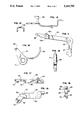
- FIG. 1 is a side elevational view, partially broken away, of a gun formed in accordance with the invention
- FIG. 2 is a view similar to FIG. 1 showing the barrel assembly in an open position
- FIG. 3 is a view similar to FIG. 1 showing the trigger partially pulled to cock the hammer
- FIG. 4 is a view similar to FIG. 3 showing the trigger pulled to release the hammer and fire the gun;
- FIG. 5 is a sectional view of the rotary ammunition cylinder
- FIG. 6 is a front elevational view of the ammunition cylinder
- FIG. 7 is a sectional view of the barrel detent assembly
- FIG. 8 is a side elevational view of the trigger
- FIG. 9 is a plan view of the trigger
- FIG. 10 is a rear elevational view of the trigger
- FIG. 11 is a side elevational view of the trigger link
- FIG. 12 is a top plan view of the trigger link
- FIG. 13 is a rear elevational view of the trigger link
- FIG. 14 is a side elevational view of the indexing pawl
- FIG. 15 is a front elevational view of the indexing pawl
- FIG. 16 is a side elevational view of the indexing lever
- FIG. 17 is a top plan view of the indexing lever
- FIG. 18 is a front elevational view of the indexing lever
- FIG. 19 is a side elevational view of the safety link
- FIG. 20 is a front elevational view of the safety link
- FIG. 21 is a side elevational view of the hammer
- FIG. 22 is a front elevational view of the hammer
- FIG. 23 is a sectional view of the pin roller for the hammer
- FIG. 24 is a sectional view of the valve assembly
- FIG. 25 is a sectional view taken along the line 25--25 of FIG. 24.
- FIG. 26 is a fragmentary sectional view taken along the line 26--26 of FIG. 4.
- the pistol includes a frame 31 which is provided by right and left frame halves 32 and 33 and a barrel assembly 34.
- the frame includes a grip portion 35, barrel portion 36, and a trigger housing 37.
- a trigger 38 is slidably mounted in the frame and is operatively connected to a hammer 39 which is pivotably mounted in the frame. As will be explained more fully hereinafter, the trigger is movable between a rest position illustrated in FIG. 1 and a firing position illustrated in FIG. 4. Pulling the trigger first cocks the hammer (FIG. 3) and then releases the hammer to actuate a valve assembly 40. The valve assembly releases a charge of compressed gas to fire a projectile.
- the barrel assembly 34 includes an elongated shroud or housing 44 which is pivotably connected to the frame 31 by a pin 45.
- the barrel assembly is maintained in the closed or firing position illustrated in FIG. 1 by a latch 46 which is slidably mounted in the barrel housing and which extends into a recess in the frame.
- a spring 47 pivots the barrel assembly clockwise to the open or loading position illustrated in FIG. 2 when the latch is moved forwardly.
- a rotary ammunition cylinder 49 is rotatably mounted in the barrel housing by a pin 50.
- the cylinder is provided with a central recess 51 for the pivot pin 50 and a plurality of bores 52 for retaining ammunition such as pellets.
- the forward portion of the cylinder is provided with coring or grooves 53 between adjacent bores 52.
- the front end of the cylinder is provided with a plurality of conventional indexing ratchet teeth 54 for rotating the cylinder.
- An elongated barrel 56 is mounted in the barrel housing.
- the barrel has an internal bore 57, and the rear end of the bore is flared outwardly to facilitate receiving a projectile when the gun is fired.
- the rotational axis of the ammunition cylinder is parallel to the axis of the barrel.
- An indexing assembly 59 on the barrel housing includes an index lever 60 and an index pawl 61.
- the index lever includes a longitudinally extending forward portion 62 and a downwardly angled rear portion 63.
- the lever is pivotably mounted on the barrel housing by a pin 64 which extends laterally from the forward portion 62 into a recess in the barrel housing, and the lever is resiliently biased to rotate clockwise by an index spring 65 which fits over a retainer pin 66 on the lever.
- the pawl 61 (FIGS. 14 and 15) includes a ratchet-engaging point 68 and a curved spring portion 69 which is formed integrally with the remainder of the pawl.
- the pawl is advantageously molded from plastic such as Black Delrin II 100, and the curved spring portion is flexible and resilient.
- the pawl 61 is pivotably mounted on the lever 60 by a pin 70 (FIGS. 16-18) on the rear end of the lever which extends into an opening 71 in the pawl.
- the spring 69 engages a shoulder 72 on the lever for resiliently biasing the pawl to rotate in the counterclockwise direction.
- the lever is advantageously molded from plastic such as Black Zytel 70633.
- the indexing mechanism can be tested independently of the frame before the barrel assembly is mounted on the frame. Independent testing of the indexing mechanism improves economy and reliability of the product.
- the trigger 38 includes a curved finger portion 74 and a mounting portion 75.
- the mounting portion 75 includes a flat bottom surface 76 and flat side surfaces 77 and 78 which engages flat surfaces on the frame 31 for maintaining the alignment of the trigger as the trigger moves between its rest and firing positions.
- a pair of upper lateral projections 79 on the mounting portion of the trigger and a pair of lower lateral projections 80 on the finger portion are slidably received in longitudinal recesses in the frame for guiding the movement of the trigger.
- the right side of the mounting portion 75 of the trigger includes a camming ramp 81 which extends at an angle of about 55 degrees from the horizontal.
- the camming ramp 81 is engageable with an angled flat camming surface 82 (FIG. 16) on the index lever 60 which also extends at an angle of about 55 degrees from the flat top and bottom surfaces of the lever.
- the cam 81 forces the index lever 60 and the index cam to rotate clockwise about the pivot pin 64 and rotates the cylinder 49.
- the angled rear portion of the index lever is confined between the flat surface 84 on the trigger and the frame 31.
- the flat surfaces 76-78 of the trigger and the mating flat surfaces of the frame 31 and the flat surface 84 extend parallel to the axis of the barrel and the axis of rotation of the ammunition cylinder.
- the index lever and index pawl are thereby maintained in proper alignment through the firing sequence. The need for secondary detenting of the index assembly is thereby eliminated.
- an alignment pin 86 enters one of the grooves 53 on the outside of the cylinder. If an ammunition bore 52 is not precisely aligned with the barrel 56, the alignment pin will cam the cylinder into precise alignment.
- the alignment pin includes curved camming surfaces 87 (FIGS. 8, 9, and 26) on the top and sides thereof for engaging and camming the cylinder as the pin enters the center of the groove 53. The alignment pin is positioned in front of the cylinder during indexing of the cylinder by the pawl.
- a trigger link 91 (FIGS. 1, 11-13) is pivotably connected to the rear of the trigger by a pin 92 (FIG. 1) which extends through an opening 93 in the trigger link and an opening 94 (FIG. 8) in the trigger.
- the rear end of the trigger link is provided with a notch 95 which is engageable with a roller 96 (FIG. 1) on the hammer 39 for cocking the hammer as the trigger is pulled.
- the trigger link includes a lever portion 97 which extends within a recess 98 (FIG. 9 and 10) in the rear of the trigger.
- a trigger spring 99 (FIG. 1) extends from a recess 100 in the frame 31 into a recess 101 (FIG. 10) in the trigger. The spring 99 resiliently biases the trigger link to rotate counterclockwise and resiliently biases the trigger toward its rest position of FIG. 1. The need for separate springs for the trigger and the trigger link is therefore eliminated.
- a safety link 104 is rotatably mounted on the trigger link adjacent the notch 95.
- the trigger link includes a U-shaped saddle portion 105 which is provided with openings 106.
- the safety link 104 includes a pivot pin portion 107 which extends through the openings 106, an intermediate portion 108, and an impact portion 109 which extends parallel to the pivot pin 107.
- the hammer 39 is pivotably mounted on the frame 31 by a hammer pin 111 and is resiliently biased to rotate clockwise by a hammer spring 112 which is connected to a pin 113 on the hammer and a pin 114 on the frame 31.
- a pin 115 is mounted on the hammer and rotatably supports a cylindrical roller 96 (FIG. 23).
- a cam 117 projects laterally from one side of the trigger and is advantageously formed integrally with the trigger.
- the hammer and cam can be formed integrally from sintered iron or metal alloy.
- the hammer includes a impact portion 118 for actuating the valve assembly 40.
- the notch 95 on the trigger link 81 engages the roller 96 on the hammer, which provides a detent or abutment between the hammer and the trigger link.
- the hammer is thereby rotated counterclockwise to the cocked position illustrated in FIG. 3.
- the cam 117 engages the trigger link and lifts the notch 96 out of engagement with the roller 96, permitting the hammer to rotate to the fired position of FIG. 4.
- the safety link 104 is moved into a position between the impact portion 118 of the hammer and a valve stem 120 in the valve assembly 40 so that the valve stem will be forced forwardly by the hammer.
- the safety link will not be positioned between the hammer and the valve stem, and the gun will not fire.
- Rotatably mounting the safety link on the trigger link rather than on the trigger eliminates the need for a trigger extension to keep the intermediate portion 108 of the safety link perpendicular to the valve stem 120. The perpendicular position allows transfer of maximum energy from the hammer to the valve stem.
- the cam 117 on the hammer prevents the trigger link from falling downwardly if the hammer is cocked without pulling the trigger.
- the trigger link will be supported by the cam so that the trigger link can engage the roller 96 when the hammer returns to the fired position. If the trigger link were permitted to fall downwardly so that it could no longer engage the roller, the gun would be inoperative.
- the valve assembly 40 includes a valve body 122 in which the valve stem 120 is slidably mounted.
- the valve stem 120 includes a cylindrical forward portion 123 and a rear pin portion 124.
- the pin portion 124 extends through an annular valve seal 125 and a spool-shaped valve seal retainer 126.
- the valve seal retainer is inserted linearly or axially into the valve body and is retained by a pair of retainer pins 127 and 128 which extend through the wall of the valve body into an annular groove 129 in the valve seal retainer.
- the pins 127 and 128 are offset from a diameter through the valve body, one pin above the diameter and one pin below the diameter, to prevent the valve seal retainer from rocking within the valve body.
- valve seal retainer The forward end of the valve seal retainer is provided with an annular recess for receiving an O-ring 130 which provides a gas-tight seal between the valve seal retainer and the valve body.
- the valve seal retainer is preferably formed from brass, and the valve seal 125 is preferably formed from Hytrel.
- the valve stem 120 includes a central bore 132, an annular valve seal 133, and three orifices 134 which provide communication between the bore 132 and the exterior of the valve stem.
- the valve seat 133 is resiliently biased against the valve seal 125 to seal the orifice 134 by a spring 135.
- the rear end of the spring engages a shoulder 136 on the valve stem, and the front end of the spring engages an annular washer 137.
- the washer engages a shoulder 138 on the valve body, and an O-ring 139 provides a gas-tight seal between the forward end of the valve stem and the valve body.
- the annular space 141 between the valve stem and the valve body provides a reservoir for compressed gas.
- the compressed gas is supplied by a conventional CO 2 cartridge 142 (FIG. 1) which is positioned in a recess in the grip 35.
- the compressed gas can also be air which is provided by a conventional air pump.
- the CO 2 cartridge is forced into a conventional piercing assembly 143 in the bottom of the grip by a conventional bracket assembly 144 (FIG. 1).
- a detent housing 147 (FIGS. 1 and 7) is ensleeved over the forward end of the valve body, and a cylindrical detent 148 is slidably mounted within the detent housing.
- An O-ring 149 is retained between a pair of annular ribs 150 and 151 to provide a gas-tight seal between the detent and the detent housing.
- a spring 152 (FIG. 1) resiliently biases the detent toward the barrel 56.
- An inwardly extending lip 152 on the front end of the detent housing retains the detent in the housing when the barrel assembly is open (FIG. 2).
- the valve assembly 40 provides means for firing a projectile from the ammunition cylinder 49 through the barrel 56.
- the valve stem is forced forwardly so that the valve seat 133 moves out of engagement with the valve seal 125.
- a charge of compressed gas in the reservoir 141 is released through the orifices 134 and central bore 132 of the valve stem and forces a projectile in the ammunition bore 52 which is aligned with the barrel out of the barrel.
- the spring 135 returns the valve stem to its sealing position after the impact energy of the hammer dissipates.
- the annular groove 129 in the valve seal retainer 126 and the retention pins 127 and 128 permit the valve seal retainer to be inserted linearly into the valve body and eliminates the need for threading the valve body and the valve seal retainer.
- the omission of the threading steps eliminates the possibility of chips from a threading operation, which could contaminate the components of the valve assembly and cause leakage.
- the pins 127 and 128 are offset from a diameter through the valve body to prevent the valve retainer from rocking within the valve body. If the pins were located on a diameter, they could act as pivot pins for the valve seal retainer and allow the valve seal retainer to rock within the valve body to the extent of clearance between the valve seal retainer and the valve body when the gun fires. Since the force from the safety link 104 is rotational, the safety link could cause uneven side-to-side loading on the valve seal retainer due to friction. By staggering the pins from side-to-side off of the diameter through the valve seal retainer, a shoulder is created which prevents the valve seal retainer from rocking during firing. The valve seal retainer is held firmly against the pins by the force from spring 135 and by the force created by the CO 2 pressure within the valve body.
- the linear assembly of the valve assembly also eliminates relative rotation between the valve stem 120 and the valve seal 125 as the valve assembly is assembled. Relative rotation between those parts could mar or tear the valve seal and adversely affect the gas-tight seal. Relative rotation between the valve seal and the valve stem after assembly is prevented by friction between the valve seal and the valve seal retainer caused by the O-ring 130 which is compressed between the valve seal and valve seal retainer and by the friction force exerted o the valve stem by the compressed spring 135.
Abstract
Description
Claims (13)
Priority Applications (5)
| Application Number | Priority Date | Filing Date | Title |
|---|---|---|---|
| US07/737,209 US5160795A (en) | 1991-07-29 | 1991-07-29 | Gun with pivoting barrel, rotary ammunition cylinder, and double action firing mechanism |
| ES09102591A ES2049149B1 (en) | 1991-07-29 | 1991-11-21 | GUN WITH PIVOTING BARREL, ROTATING AMMUNITION CYLINDER, AND DOUBLE ACTION FIRE MECHANISM. |
| CA002062643A CA2062643A1 (en) | 1991-07-29 | 1992-03-11 | Gun with pivoting barrel, rotary ammunition cylinder, and double action firing mechanism |
| US07/901,774 US5400536A (en) | 1991-07-29 | 1992-06-22 | Gun with pivoting barrel, rotary ammunition cylinder, and double action firing mechanism |
| US08/308,358 US5704150A (en) | 1991-07-29 | 1994-09-19 | Gun with pivoting barrel, rotary ammunition cylinder, and double action firing mechanism |
Applications Claiming Priority (1)
| Application Number | Priority Date | Filing Date | Title |
|---|---|---|---|
| US07/737,209 US5160795A (en) | 1991-07-29 | 1991-07-29 | Gun with pivoting barrel, rotary ammunition cylinder, and double action firing mechanism |
Related Child Applications (1)
| Application Number | Title | Priority Date | Filing Date |
|---|---|---|---|
| US07/901,774 Division US5400536A (en) | 1991-07-29 | 1992-06-22 | Gun with pivoting barrel, rotary ammunition cylinder, and double action firing mechanism |
Publications (1)
| Publication Number | Publication Date |
|---|---|
| US5160795A true US5160795A (en) | 1992-11-03 |
Family
ID=24963006
Family Applications (3)
| Application Number | Title | Priority Date | Filing Date |
|---|---|---|---|
| US07/737,209 Expired - Fee Related US5160795A (en) | 1991-07-29 | 1991-07-29 | Gun with pivoting barrel, rotary ammunition cylinder, and double action firing mechanism |
| US07/901,774 Expired - Fee Related US5400536A (en) | 1991-07-29 | 1992-06-22 | Gun with pivoting barrel, rotary ammunition cylinder, and double action firing mechanism |
| US08/308,358 Expired - Lifetime US5704150A (en) | 1991-07-29 | 1994-09-19 | Gun with pivoting barrel, rotary ammunition cylinder, and double action firing mechanism |
Family Applications After (2)
| Application Number | Title | Priority Date | Filing Date |
|---|---|---|---|
| US07/901,774 Expired - Fee Related US5400536A (en) | 1991-07-29 | 1992-06-22 | Gun with pivoting barrel, rotary ammunition cylinder, and double action firing mechanism |
| US08/308,358 Expired - Lifetime US5704150A (en) | 1991-07-29 | 1994-09-19 | Gun with pivoting barrel, rotary ammunition cylinder, and double action firing mechanism |
Country Status (3)
| Country | Link |
|---|---|
| US (3) | US5160795A (en) |
| CA (1) | CA2062643A1 (en) |
| ES (1) | ES2049149B1 (en) |
Cited By (51)
| Publication number | Priority date | Publication date | Assignee | Title |
|---|---|---|---|---|
| US5285766A (en) * | 1992-07-30 | 1994-02-15 | Crosman Corporation | Gun with removable rotary ammunition clip |
| US5404863A (en) * | 1993-01-06 | 1995-04-11 | Poor; Keith A. | Gas-powered, single-shot gun with tip-up barrel for loading |
| EP0647825A1 (en) * | 1993-10-08 | 1995-04-12 | Western Arms | Model gun with automatic bullet supplying mechanism |
| EP0704668A1 (en) | 1994-09-27 | 1996-04-03 | Industrias El Gamo, S.A. | Improvements in the gas-powered guns of the revolver type |
| FR2726077A1 (en) * | 1994-10-24 | 1996-04-26 | Gamo Ind Sa | Gas-powered guns of revolver type |
| WO1997018431A1 (en) * | 1995-11-14 | 1997-05-22 | Umarex Sportwaffen Gmbh & Co. Kg | Compressed gas-operated shooting weapon |
| US5632264A (en) * | 1995-06-07 | 1997-05-27 | Crosman Corporation | Spring air gun with pivoting barrel |
| FR2744207A1 (en) * | 1996-01-26 | 1997-08-01 | Manuf D Armes Des Pyrenees Fra | COMPRESSED GAS GUN |
| US5704150A (en) * | 1991-07-29 | 1998-01-06 | Crosman Corporation | Gun with pivoting barrel, rotary ammunition cylinder, and double action firing mechanism |
| US5711286A (en) * | 1995-06-02 | 1998-01-27 | Anics Corp. | Gas-powered repeating pistol |
| GB2319074A (en) * | 1996-11-06 | 1998-05-13 | Constantia | Gas cartridge |
| WO1998027398A1 (en) * | 1996-12-18 | 1998-06-25 | Umarex Sportwaffen Gmbh & Co. Kg | Compressed-gas firearm |
| US5775312A (en) * | 1997-02-10 | 1998-07-07 | Crosman Corporation | Spring air gun with interlocking mechanism |
| FR2811417A1 (en) | 2000-07-06 | 2002-01-11 | Ind El Gamo | COMPRESSED AIR OR GAS GUN |
| US6385888B1 (en) * | 2000-02-25 | 2002-05-14 | Ron Power | Revolver firing mechanism with disengaging cylinder pawl |
| US20040079352A1 (en) * | 2002-08-29 | 2004-04-29 | Carlo Piccini | Magazine with a plurality of cylinders in series, in particular for compressed-air guns |
| US20040237952A1 (en) * | 2003-05-28 | 2004-12-02 | Maruzen Company Limited | Airgun firing mechanism |
| EP1491846A1 (en) * | 2003-06-25 | 2004-12-29 | Western Arms | Gas supplying mechanism in a gas powered toy gun |
| US20050257783A1 (en) * | 2004-05-19 | 2005-11-24 | Tippmann Dennis J Jr | Valve arrangement |
| ES2265795A1 (en) * | 2006-07-05 | 2007-02-16 | Industrial El Gamo, S.A. | Sports firearm with gas propulsion has rigger operation device that includes hammer, tie pawl joined to trigger and hammer, and distributor arranged in communication with valve, drum and track |
| US20080168974A1 (en) * | 2006-10-05 | 2008-07-17 | Crosman Corporation | Magazine Assembly for Presenting a Pressure Cartridge to a Compressed Gas Powered Device |
| US20080168972A1 (en) * | 2007-01-16 | 2008-07-17 | Wilson Wei | Air cylinder mounting structure for air gun |
| CN100404998C (en) * | 2003-07-29 | 2008-07-23 | 株式会社西方武器 | Gas powered toy gun |
| EP2031339A2 (en) | 2007-08-31 | 2009-03-04 | Maruzen Company Limited | Rotary clip rotation mechanism for air gun |
| US20090056690A1 (en) * | 2007-08-28 | 2009-03-05 | Maruzen Company Limited | Magazine ejector structure for air gun |
| US20090139507A1 (en) * | 2007-11-30 | 2009-06-04 | Maruzen Company Limited | Magazine for air gun having rotary clip |
| US20100192930A1 (en) * | 2009-02-04 | 2010-08-05 | Lammonds Timothy R | Scent Distributing Airgun |
| US20100305624A1 (en) * | 2009-05-26 | 2010-12-02 | Zimmer, Inc. | Bone fixation tool |
| CZ303397B6 (en) * | 2011-09-19 | 2012-08-29 | Pintera@Vladislav | Sealed single-action revolver |
| US8752319B2 (en) * | 2011-06-08 | 2014-06-17 | Daniel Kunau | Gap seal for gun |
| US8950387B2 (en) | 2013-01-25 | 2015-02-10 | Kee Action Sports I Llc | Paintball marker with split body |
| US9250033B1 (en) * | 2015-03-30 | 2016-02-02 | Ho-Sheng Wei | Trigger linkage mechanism for use in toy gun |
| US9423196B2 (en) | 2013-12-30 | 2016-08-23 | Daniel Kunau | Gap seal for projectile launching device |
| US9523550B2 (en) * | 2012-08-29 | 2016-12-20 | Real Action Paintball (Rap4), Inc. | Projectile launcher able to launch an object using a hammer |
| US9664475B1 (en) | 2016-09-16 | 2017-05-30 | Loren Maggiore | Prepackaged bug gun magazine |
| EP3173728A1 (en) * | 2015-11-30 | 2017-05-31 | Maruzen Company Limited | Threadless air gun valve |
| EP3179195A1 (en) | 2015-12-10 | 2017-06-14 | Maruzen Company Limited | Trigger and loading mechanism for an air gun |
| US20170199005A1 (en) * | 2016-01-13 | 2017-07-13 | Smith & Wesson Corp. | Self-Captured Detent Mechanism |
| US9987067B2 (en) | 2012-07-11 | 2018-06-05 | Zimmer, Inc. | Bone fixation tool |
| US10179017B2 (en) | 2014-04-03 | 2019-01-15 | Zimmer, Inc. | Orthopedic tool for bone fixation |
| US10209021B1 (en) * | 2017-11-16 | 2019-02-19 | Kien Well Toy Industrial Co., Ltd. | Interlocking, positioning and firing device for toy gun |
| US10337823B2 (en) * | 2016-07-27 | 2019-07-02 | Crosman Corporation | Break barrel airgun having active interlock |
| CN110081775A (en) * | 2019-06-17 | 2019-08-02 | 李昌华 | A kind of automatic feed machanism and Semi-automatic air gun of Semi-automatic air gun |
| US10627187B1 (en) * | 2018-10-30 | 2020-04-21 | Kuan Ting Lin | Shooting controller of paintball gun |
| US10704859B2 (en) | 2018-11-06 | 2020-07-07 | Gi Sportz Direct Llc | Compressed gas gun front grip having battery access panel |
| WO2020253095A1 (en) * | 2019-06-17 | 2020-12-24 | 李昌华 | Automated bullet loading device for semi-automatic air gun, and semi-automatic air gun |
| US10966704B2 (en) | 2016-11-09 | 2021-04-06 | Biomet Sports Medicine, Llc | Methods and systems for stitching soft tissue to bone |
| US11002508B2 (en) * | 2018-09-20 | 2021-05-11 | Crosman Corporation | Multi-shot airgun |
| US11029124B2 (en) * | 2019-01-17 | 2021-06-08 | Crosman Corporation | Multi-shot airgun |
| RU2771299C1 (en) * | 2021-11-25 | 2022-04-29 | Роман Викторович Миночкин | Revolver |
| US20230046456A1 (en) * | 2017-09-25 | 2023-02-16 | Umarex Usa, Inc. | Dynamic sealing chamber magazine |
Families Citing this family (18)
| Publication number | Priority date | Publication date | Assignee | Title |
|---|---|---|---|---|
| US6164001A (en) * | 1998-06-29 | 2000-12-26 | Lee; Roberto R. | Device for reducing firearms trigger pull weight |
| US6415702B1 (en) * | 1998-11-23 | 2002-07-09 | Angelotti, Inc. | Double action semi-automatic handgun |
| ES2194564B2 (en) * | 2000-10-13 | 2005-07-16 | Industrias El Gamo, S.A. | ARTICULATION DEVICE OF A GUN IN A CARBON OR COMPRESSED AIR GUN OF RUNNING GUN. |
| US6874492B1 (en) | 2001-01-09 | 2005-04-05 | New-Matics Licensing, Llc | Compressed gas-powered gun simulating the recoil of a conventional firearm |
| US6820608B2 (en) * | 2001-01-09 | 2004-11-23 | New-Matics Licencing, Llc | Compressed gas-powered gun simulating the recoil of a conventional firearm |
| BE1014951A4 (en) | 2001-09-14 | 2004-07-06 | Hubert Leon | Compressed air distributor automatic operation. |
| US6640480B2 (en) * | 2002-01-23 | 2003-11-04 | Lawrence J. Williams | Gun cleaning kit |
| US6877265B2 (en) * | 2002-03-14 | 2005-04-12 | Snake River Machine, Inc. | System and method for increased magazine capacity for a firearm |
| US20080121096A1 (en) * | 2002-03-14 | 2008-05-29 | Jeffrey Hajjar | System and method for loading and feeding a shotgun |
| US6736619B2 (en) * | 2002-07-22 | 2004-05-18 | Scott Wu | Air pump with rotatable discharge tube |
| CA2711799C (en) * | 2007-01-09 | 2015-03-31 | S/R Industries | Interchangeable gun barrel system and related methods |
| US8434465B2 (en) * | 2009-07-24 | 2013-05-07 | Crosman Corporation | Blowback assembly |
| US20120208430A1 (en) * | 2011-02-10 | 2012-08-16 | Vega Force International Corp. | Loading/unloading module of electric toy gun |
| DE102014103098B4 (en) * | 2014-03-07 | 2020-10-01 | STEYR Sport GmbH | Compressed gas weapon |
| ES2627296B1 (en) * | 2016-01-19 | 2018-06-21 | Gamo Outdoor, S.L. | Ball loading system |
| RU2758734C1 (en) * | 2018-06-08 | 2021-11-01 | Гамо Аутдор, С.Л. | System for charging bullets |
| US11662173B1 (en) | 2021-01-31 | 2023-05-30 | Hasbro, Inc. | Apparatus and methods for launch toys having rotatable projectile carriers |
| US11953286B1 (en) | 2021-07-09 | 2024-04-09 | Hasbro, Inc. | Rapid fire toy launch apparatus |
Citations (18)
| Publication number | Priority date | Publication date | Assignee | Title |
|---|---|---|---|---|
| US211743A (en) * | 1879-01-28 | Improvement in revolving fire-arms | ||
| US373893A (en) * | 1887-11-29 | Forehand | ||
| US422930A (en) * | 1890-03-11 | Lock for fire-arms | ||
| US1049105A (en) * | 1911-05-05 | 1912-12-31 | William Warren Key | Revolver. |
| US2150914A (en) * | 1935-01-15 | 1939-03-21 | Alonzo F Gaidos | Attachment for firearms |
| US2723656A (en) * | 1951-07-18 | 1955-11-15 | Andina Boris | Compressed gas pistol |
| US2980096A (en) * | 1959-01-12 | 1961-04-18 | Crosman Arms Company Inc | Gas powered revolver |
| US3212489A (en) * | 1963-04-05 | 1965-10-19 | Crosman Arms Company Inc | Gas-powered revolver |
| US3612026A (en) * | 1970-03-18 | 1971-10-12 | Crosman Arms Co Inc | Gas-operated revolver with rotatable magazine |
| US3726266A (en) * | 1970-10-28 | 1973-04-10 | Palmer Chem & Equipment Co Inc | Gas-operated multiple shot projectile firing device |
| US3741189A (en) * | 1971-03-29 | 1973-06-26 | Crosman Arms Co Inc | Gas operated pellet gun with removable clip loader |
| US4143636A (en) * | 1977-07-12 | 1979-03-13 | The Coleman Company, Inc. | Gun with safety link for firing mechanism thereof |
| US4336787A (en) * | 1980-07-21 | 1982-06-29 | Giacomo Cagnoni | Pre-compressed air weapon |
| US4422433A (en) * | 1982-05-24 | 1983-12-27 | The Coleman Company, Inc. | Projectile loader and detent assembly for guns |
| US4555861A (en) * | 1983-12-16 | 1985-12-03 | Colt Industries Operating Corp | Firing pin locking device |
| US4589327A (en) * | 1983-03-28 | 1986-05-20 | Smith David E | Firing lock with safety system for self loading fire arms |
| US4774929A (en) * | 1986-10-09 | 1988-10-04 | The Coleman Company, Inc. | Gun with pivoting barrel and lever for retaining barrel in position or permitting barrel to pviot |
| US4841840A (en) * | 1987-04-22 | 1989-06-27 | Bent Agner | Firing mechanism for a semi-automatic arm |
Family Cites Families (8)
| Publication number | Priority date | Publication date | Assignee | Title |
|---|---|---|---|---|
| US373898A (en) * | 1887-11-29 | Ventilating apparatus for railway-cars | ||
| GB189810145A (en) * | 1898-05-03 | 1898-06-04 | Alfred Lines | Improvements in Repeating Fire-arms, more especially applicable to Revolvers. |
| GB607444A (en) * | 1946-02-04 | 1948-08-31 | Leslie Wesley | Improvements in or relating to pistols |
| US4173964A (en) * | 1977-02-04 | 1979-11-13 | Bangor Punta Operations, Inc. | Safety for the trigger mechanism of a gun |
| DE3147068A1 (en) * | 1981-11-27 | 1983-06-09 | Feinwerkbau Westinger & Altenburger GmbH & Co KG, 7238 Oberndorf | CO (DOWN ARROW) 2 (DOWN ARROW) ARM |
| IT1169865B (en) * | 1983-10-21 | 1987-06-03 | Emilio Ghisoni | LOWERED DRUM REVOLT |
| FR2592471B1 (en) * | 1985-12-27 | 1989-10-13 | France Etat Armement | COMPRESSED GAS SUPPLY DEVICE FOR WEAPONS. |
| US5160795A (en) * | 1991-07-29 | 1992-11-03 | Crosman Corporation | Gun with pivoting barrel, rotary ammunition cylinder, and double action firing mechanism |
-
1991
- 1991-07-29 US US07/737,209 patent/US5160795A/en not_active Expired - Fee Related
- 1991-11-21 ES ES09102591A patent/ES2049149B1/en not_active Expired - Fee Related
-
1992
- 1992-03-11 CA CA002062643A patent/CA2062643A1/en not_active Abandoned
- 1992-06-22 US US07/901,774 patent/US5400536A/en not_active Expired - Fee Related
-
1994
- 1994-09-19 US US08/308,358 patent/US5704150A/en not_active Expired - Lifetime
Patent Citations (18)
| Publication number | Priority date | Publication date | Assignee | Title |
|---|---|---|---|---|
| US211743A (en) * | 1879-01-28 | Improvement in revolving fire-arms | ||
| US373893A (en) * | 1887-11-29 | Forehand | ||
| US422930A (en) * | 1890-03-11 | Lock for fire-arms | ||
| US1049105A (en) * | 1911-05-05 | 1912-12-31 | William Warren Key | Revolver. |
| US2150914A (en) * | 1935-01-15 | 1939-03-21 | Alonzo F Gaidos | Attachment for firearms |
| US2723656A (en) * | 1951-07-18 | 1955-11-15 | Andina Boris | Compressed gas pistol |
| US2980096A (en) * | 1959-01-12 | 1961-04-18 | Crosman Arms Company Inc | Gas powered revolver |
| US3212489A (en) * | 1963-04-05 | 1965-10-19 | Crosman Arms Company Inc | Gas-powered revolver |
| US3612026A (en) * | 1970-03-18 | 1971-10-12 | Crosman Arms Co Inc | Gas-operated revolver with rotatable magazine |
| US3726266A (en) * | 1970-10-28 | 1973-04-10 | Palmer Chem & Equipment Co Inc | Gas-operated multiple shot projectile firing device |
| US3741189A (en) * | 1971-03-29 | 1973-06-26 | Crosman Arms Co Inc | Gas operated pellet gun with removable clip loader |
| US4143636A (en) * | 1977-07-12 | 1979-03-13 | The Coleman Company, Inc. | Gun with safety link for firing mechanism thereof |
| US4336787A (en) * | 1980-07-21 | 1982-06-29 | Giacomo Cagnoni | Pre-compressed air weapon |
| US4422433A (en) * | 1982-05-24 | 1983-12-27 | The Coleman Company, Inc. | Projectile loader and detent assembly for guns |
| US4589327A (en) * | 1983-03-28 | 1986-05-20 | Smith David E | Firing lock with safety system for self loading fire arms |
| US4555861A (en) * | 1983-12-16 | 1985-12-03 | Colt Industries Operating Corp | Firing pin locking device |
| US4774929A (en) * | 1986-10-09 | 1988-10-04 | The Coleman Company, Inc. | Gun with pivoting barrel and lever for retaining barrel in position or permitting barrel to pviot |
| US4841840A (en) * | 1987-04-22 | 1989-06-27 | Bent Agner | Firing mechanism for a semi-automatic arm |
Cited By (83)
| Publication number | Priority date | Publication date | Assignee | Title |
|---|---|---|---|---|
| US5704150A (en) * | 1991-07-29 | 1998-01-06 | Crosman Corporation | Gun with pivoting barrel, rotary ammunition cylinder, and double action firing mechanism |
| US5285766A (en) * | 1992-07-30 | 1994-02-15 | Crosman Corporation | Gun with removable rotary ammunition clip |
| US5404863A (en) * | 1993-01-06 | 1995-04-11 | Poor; Keith A. | Gas-powered, single-shot gun with tip-up barrel for loading |
| EP0647825A1 (en) * | 1993-10-08 | 1995-04-12 | Western Arms | Model gun with automatic bullet supplying mechanism |
| EP0704668A1 (en) | 1994-09-27 | 1996-04-03 | Industrias El Gamo, S.A. | Improvements in the gas-powered guns of the revolver type |
| US5622160A (en) * | 1994-09-27 | 1997-04-22 | Industrias El Gamo, S.A. | Gas-powered guns of the revolver type |
| ES2124110A1 (en) * | 1994-09-27 | 1999-01-16 | Gamo Ind Sa | Improvements in the gas-powered guns of the revolver type |
| FR2726077A1 (en) * | 1994-10-24 | 1996-04-26 | Gamo Ind Sa | Gas-powered guns of revolver type |
| US5711286A (en) * | 1995-06-02 | 1998-01-27 | Anics Corp. | Gas-powered repeating pistol |
| US5632264A (en) * | 1995-06-07 | 1997-05-27 | Crosman Corporation | Spring air gun with pivoting barrel |
| DE19542332C1 (en) * | 1995-11-14 | 1997-05-28 | Umarex Gmbh & Co Kg | Pressurized gas firearm |
| WO1997018431A1 (en) * | 1995-11-14 | 1997-05-22 | Umarex Sportwaffen Gmbh & Co. Kg | Compressed gas-operated shooting weapon |
| FR2744207A1 (en) * | 1996-01-26 | 1997-08-01 | Manuf D Armes Des Pyrenees Fra | COMPRESSED GAS GUN |
| GB2319074A (en) * | 1996-11-06 | 1998-05-13 | Constantia | Gas cartridge |
| GB2319074B (en) * | 1996-11-06 | 2000-08-02 | Constantia | Gas cartridge |
| WO1998027398A1 (en) * | 1996-12-18 | 1998-06-25 | Umarex Sportwaffen Gmbh & Co. Kg | Compressed-gas firearm |
| US5775312A (en) * | 1997-02-10 | 1998-07-07 | Crosman Corporation | Spring air gun with interlocking mechanism |
| US6385888B1 (en) * | 2000-02-25 | 2002-05-14 | Ron Power | Revolver firing mechanism with disengaging cylinder pawl |
| GB2364368A (en) * | 2000-07-06 | 2002-01-23 | Ind E1 Gamo Sa | Air or gas-powered gun |
| FR2811417A1 (en) | 2000-07-06 | 2002-01-11 | Ind El Gamo | COMPRESSED AIR OR GAS GUN |
| US6578565B2 (en) | 2000-07-06 | 2003-06-17 | Industrias El Gemo, Sa | Air or gas-powered guns |
| GB2364368B (en) * | 2000-07-06 | 2004-04-07 | Ind E1 Gamo Sa | An air or gas-operated gun comprising a locking safety device |
| US20040079352A1 (en) * | 2002-08-29 | 2004-04-29 | Carlo Piccini | Magazine with a plurality of cylinders in series, in particular for compressed-air guns |
| US6745755B2 (en) * | 2002-08-29 | 2004-06-08 | Valtro Europe S.R.L. | Magazine with a plurality of cylinders in series, in particular for compressed-air guns |
| US20040237952A1 (en) * | 2003-05-28 | 2004-12-02 | Maruzen Company Limited | Airgun firing mechanism |
| US7159584B2 (en) | 2003-05-28 | 2007-01-09 | Maruzen Company Limited | Airgun firing mechanism |
| EP1491846A1 (en) * | 2003-06-25 | 2004-12-29 | Western Arms | Gas supplying mechanism in a gas powered toy gun |
| US20050011508A1 (en) * | 2003-06-25 | 2005-01-20 | Western Arms | Gas supplying mechanism in a gas powered toy gun |
| CN100404998C (en) * | 2003-07-29 | 2008-07-23 | 株式会社西方武器 | Gas powered toy gun |
| US20070017406A1 (en) * | 2004-05-19 | 2007-01-25 | Tippmann Dennis J Jr | Valve arrangement |
| US20050257783A1 (en) * | 2004-05-19 | 2005-11-24 | Tippmann Dennis J Jr | Valve arrangement |
| ES2265795A1 (en) * | 2006-07-05 | 2007-02-16 | Industrial El Gamo, S.A. | Sports firearm with gas propulsion has rigger operation device that includes hammer, tie pawl joined to trigger and hammer, and distributor arranged in communication with valve, drum and track |
| US20080168974A1 (en) * | 2006-10-05 | 2008-07-17 | Crosman Corporation | Magazine Assembly for Presenting a Pressure Cartridge to a Compressed Gas Powered Device |
| US7757682B2 (en) * | 2006-10-05 | 2010-07-20 | Crosman Corporation | Magazine assembly for presenting a pressure cartridge to a compressed gas powered device |
| US20080168972A1 (en) * | 2007-01-16 | 2008-07-17 | Wilson Wei | Air cylinder mounting structure for air gun |
| US7591261B2 (en) * | 2007-01-16 | 2009-09-22 | Wilson Wei | Air cylinder mounting structure for air gun |
| US7950381B2 (en) * | 2007-08-28 | 2011-05-31 | Maruzen Company Limited | Magazine ejector structure for air gun |
| US20090056690A1 (en) * | 2007-08-28 | 2009-03-05 | Maruzen Company Limited | Magazine ejector structure for air gun |
| EP2031340A3 (en) * | 2007-08-28 | 2010-04-07 | Maruzen Company Limited | Magazine ejector structure for air gun |
| US7669588B2 (en) | 2007-08-31 | 2010-03-02 | Maruzen Company Ltd. | Rotary clip rotation for air gun |
| US20090056692A1 (en) * | 2007-08-31 | 2009-03-05 | Maruzen Company Limited | Rotary clip rotation mechanism for air gun |
| EP2031339A3 (en) * | 2007-08-31 | 2010-04-07 | Maruzen Company Limited | Rotary clip rotation mechanism for air gun |
| EP2031339A2 (en) | 2007-08-31 | 2009-03-04 | Maruzen Company Limited | Rotary clip rotation mechanism for air gun |
| US20090139507A1 (en) * | 2007-11-30 | 2009-06-04 | Maruzen Company Limited | Magazine for air gun having rotary clip |
| US7963280B2 (en) * | 2007-11-30 | 2011-06-21 | Maruzen Company Limited | Magazine for air gun having rotary clip |
| US8118017B2 (en) * | 2009-02-04 | 2012-02-21 | Lammonds Timothy R | Scent distributing airgun |
| US20100192930A1 (en) * | 2009-02-04 | 2010-08-05 | Lammonds Timothy R | Scent Distributing Airgun |
| US8603102B2 (en) | 2009-05-26 | 2013-12-10 | Zimmer, Inc. | Bone fixation tool |
| US8221433B2 (en) | 2009-05-26 | 2012-07-17 | Zimmer, Inc. | Bone fixation tool |
| US8852202B2 (en) | 2009-05-26 | 2014-10-07 | Zimmer, Inc. | Bone fixation tool |
| US20100305624A1 (en) * | 2009-05-26 | 2010-12-02 | Zimmer, Inc. | Bone fixation tool |
| US8752319B2 (en) * | 2011-06-08 | 2014-06-17 | Daniel Kunau | Gap seal for gun |
| CZ303397B6 (en) * | 2011-09-19 | 2012-08-29 | Pintera@Vladislav | Sealed single-action revolver |
| US9987067B2 (en) | 2012-07-11 | 2018-06-05 | Zimmer, Inc. | Bone fixation tool |
| US9523550B2 (en) * | 2012-08-29 | 2016-12-20 | Real Action Paintball (Rap4), Inc. | Projectile launcher able to launch an object using a hammer |
| US9518799B2 (en) | 2013-01-25 | 2016-12-13 | Gi Sportz Direct Llc | Paintball marker with secure barrel engagement |
| US8950387B2 (en) | 2013-01-25 | 2015-02-10 | Kee Action Sports I Llc | Paintball marker with split body |
| US9423196B2 (en) | 2013-12-30 | 2016-08-23 | Daniel Kunau | Gap seal for projectile launching device |
| US10179017B2 (en) | 2014-04-03 | 2019-01-15 | Zimmer, Inc. | Orthopedic tool for bone fixation |
| US9250033B1 (en) * | 2015-03-30 | 2016-02-02 | Ho-Sheng Wei | Trigger linkage mechanism for use in toy gun |
| US10184751B2 (en) | 2015-11-30 | 2019-01-22 | Maruzen Company Limited | Toy gun |
| EP3173728A1 (en) * | 2015-11-30 | 2017-05-31 | Maruzen Company Limited | Threadless air gun valve |
| EP3179195A1 (en) | 2015-12-10 | 2017-06-14 | Maruzen Company Limited | Trigger and loading mechanism for an air gun |
| TWI619924B (en) * | 2015-12-10 | 2018-04-01 | 丸前有限公司 | Toy gun |
| US9835406B2 (en) | 2015-12-10 | 2017-12-05 | Maruzen Company Limited | Toy gun |
| US9810506B2 (en) * | 2016-01-13 | 2017-11-07 | Smith & Wesson Corp. | Self-captured detent mechinism |
| US20170199005A1 (en) * | 2016-01-13 | 2017-07-13 | Smith & Wesson Corp. | Self-Captured Detent Mechanism |
| US10337823B2 (en) * | 2016-07-27 | 2019-07-02 | Crosman Corporation | Break barrel airgun having active interlock |
| US9664475B1 (en) | 2016-09-16 | 2017-05-30 | Loren Maggiore | Prepackaged bug gun magazine |
| US10966704B2 (en) | 2016-11-09 | 2021-04-06 | Biomet Sports Medicine, Llc | Methods and systems for stitching soft tissue to bone |
| US20230400279A1 (en) * | 2017-09-25 | 2023-12-14 | Umarex Usa, Inc. | Dynamic sealing chamber magazine |
| US11703302B2 (en) * | 2017-09-25 | 2023-07-18 | Umarex Usa, Inc. | Dynamic sealing chamber magazine |
| US20230046456A1 (en) * | 2017-09-25 | 2023-02-16 | Umarex Usa, Inc. | Dynamic sealing chamber magazine |
| US10209021B1 (en) * | 2017-11-16 | 2019-02-19 | Kien Well Toy Industrial Co., Ltd. | Interlocking, positioning and firing device for toy gun |
| US11002508B2 (en) * | 2018-09-20 | 2021-05-11 | Crosman Corporation | Multi-shot airgun |
| US10627187B1 (en) * | 2018-10-30 | 2020-04-21 | Kuan Ting Lin | Shooting controller of paintball gun |
| US10704859B2 (en) | 2018-11-06 | 2020-07-07 | Gi Sportz Direct Llc | Compressed gas gun front grip having battery access panel |
| US11029124B2 (en) * | 2019-01-17 | 2021-06-08 | Crosman Corporation | Multi-shot airgun |
| US11692789B2 (en) | 2019-01-17 | 2023-07-04 | Crosman Corporation | Multi-shot airgun |
| WO2020253095A1 (en) * | 2019-06-17 | 2020-12-24 | 李昌华 | Automated bullet loading device for semi-automatic air gun, and semi-automatic air gun |
| CN110081775A (en) * | 2019-06-17 | 2019-08-02 | 李昌华 | A kind of automatic feed machanism and Semi-automatic air gun of Semi-automatic air gun |
| CN110081775B (en) * | 2019-06-17 | 2024-01-05 | 李昌华 | Automatic bullet supply device of semi-automatic air gun and semi-automatic air gun |
| RU2771299C1 (en) * | 2021-11-25 | 2022-04-29 | Роман Викторович Миночкин | Revolver |
Also Published As
| Publication number | Publication date |
|---|---|
| ES2049149A2 (en) | 1994-04-01 |
| ES2049149R (en) | 1995-07-01 |
| CA2062643A1 (en) | 1993-01-30 |
| US5400536A (en) | 1995-03-28 |
| ES2049149B1 (en) | 1996-02-16 |
| US5704150A (en) | 1998-01-06 |
Similar Documents
| Publication | Publication Date | Title |
|---|---|---|
| US5160795A (en) | Gun with pivoting barrel, rotary ammunition cylinder, and double action firing mechanism | |
| US4422433A (en) | Projectile loader and detent assembly for guns | |
| US9383153B2 (en) | Fire control system for firearms | |
| US3212489A (en) | Gas-powered revolver | |
| US4590697A (en) | Ambidextrous safety mechanism | |
| US4031648A (en) | Magazine safety and ejector | |
| US7703230B2 (en) | Positive striker lock safety for use with a firearm | |
| US2930041A (en) | Cartridge operated fastening gun | |
| US5285766A (en) | Gun with removable rotary ammunition clip | |
| US8122634B2 (en) | Striker assembly for use with a firearm | |
| CA2396031A1 (en) | Pneumatic gun | |
| CZ212192A3 (en) | Smallarm | |
| EP2065668B1 (en) | Air gun | |
| US4400900A (en) | Multi-barrel handgun firing mechanism | |
| US4407085A (en) | Handgun firing mechanism | |
| US4151782A (en) | Handgun with indexing means | |
| US5161516A (en) | Compressed gas gun | |
| US3090148A (en) | Bolt action firearm with charger | |
| US20180031349A1 (en) | Break barrel airgun having active interlock | |
| US4143636A (en) | Gun with safety link for firing mechanism thereof | |
| US3119384A (en) | Gas powered gun | |
| US4897949A (en) | Firearms | |
| US3547095A (en) | Gas-operated revolver | |
| US6948273B2 (en) | Safety mechanism for gun | |
| US2503309A (en) | Firing mechanism for mortars |
Legal Events
| Date | Code | Title | Description |
|---|---|---|---|
| AS | Assignment |
Owner name: CROSMAN CORPORATION A CORP. OF DE, NEW YORK Free format text: ASSIGNMENT OF ASSIGNORS INTEREST.;ASSIGNOR:MILLIMAN, KEITH L.;REEL/FRAME:005816/0521 Effective date: 19910717 |
|
| AS | Assignment |
Owner name: HOUSEHOLD COMMERCIAL FINANCIAL SERVICES, INC., ILL Free format text: SECURITY INTEREST;ASSIGNOR:CROSMAN CORPORATION;REEL/FRAME:006714/0893 Effective date: 19930924 |
|
| AS | Assignment |
Owner name: FIRST SOURCE FINANCIAL LLP, ILLINOIS Free format text: ASSIGNMENT OF ASSIGNORS INTEREST;ASSIGNOR:HOUSEHOLD COMMERCIAL FINANCIAL SERVICES, INC., A DE CORP., AS AGENT;REEL/FRAME:007431/0312 Effective date: 19950324 |
|
| AS | Assignment |
Owner name: FIRST NATIONAL BANK OF CHICAGO, THE, AS COLLATERAL Free format text: SECURITY INTEREST;ASSIGNORS:CROSMAN CORPORATION;VOIT SPORTS, INC.;BUSHNELL CORPORATION;AND OTHERS;REEL/FRAME:007467/0268 Effective date: 19950427 |
|
| FEPP | Fee payment procedure |
Free format text: PAYOR NUMBER ASSIGNED (ORIGINAL EVENT CODE: ASPN); ENTITY STATUS OF PATENT OWNER: LARGE ENTITY |
|
| FPAY | Fee payment |
Year of fee payment: 4 |
|
| AS | Assignment |
Owner name: IBJ SCHRODER BANK & TRUST COMPANY, AS AGENT, NEW Y Free format text: SECURITY AGREEMENT;ASSIGNOR:CROSMAN CORPORATION;REEL/FRAME:008239/0041 Effective date: 19970122 |
|
| AS | Assignment |
Owner name: CROSMAN CORPORATION, NEW YORK Free format text: RELEASE;ASSIGNOR:FIRST NATIONAL BANK OF CHICAGO, THE COLLATERAL AGENT;REEL/FRAME:008239/0649 Effective date: 19970122 |
|
| AS | Assignment |
Owner name: BENJAMIN SHERIDAN CORPORATION, KANSAS Free format text: RELEASE BY SECURED PARTY;ASSIGNOR:FIRST NATIONAL BANK OF CHICAGO, THE;REEL/FRAME:010154/0571 Effective date: 19990730 Owner name: VOIT CORORATION, KANSAS Free format text: RELEASE BY SECURED PARTY;ASSIGNOR:FIRST NATIONAL BANK OF CHICAGO, THE;REEL/FRAME:010154/0571 Effective date: 19990730 Owner name: VOIT SPORTS, INC., KANSAS Free format text: RELEASE BY SECURED PARTY;ASSIGNOR:FIRST NATIONAL BANK OF CHICAGO, THE;REEL/FRAME:010154/0571 Effective date: 19990730 Owner name: BUSHNELL CORPORAITON, KANSAS Free format text: RELEASE BY SECURED PARTY;ASSIGNOR:FIRST NATIONAL BANK OF CHICAGO, THE;REEL/FRAME:010154/0571 Effective date: 19990730 Owner name: CROSMAN CORPORATION, KANSAS Free format text: RELEASE BY SECURED PARTY;ASSIGNOR:FIRST NATIONAL BANK OF CHICAGO, THE;REEL/FRAME:010154/0571 Effective date: 19990730 |
|
| AS | Assignment |
Owner name: CROSMAN CORPORATION, NEW YORK Free format text: RELEASE BY SECURED PARTY;ASSIGNOR:IBJ SCHRODER BANK & TRUST COMPANY;REEL/FRAME:010321/0825 Effective date: 19991018 Owner name: BANK OF AMERICA, N.A. AS AGENT, NEW YORK Free format text: SECURITY INTEREST;ASSIGNOR:CROSMAN CORPORATION;REEL/FRAME:010531/0102 Effective date: 19991018 |
|
| AS | Assignment |
Owner name: BANK OF AMERICA, N.A., AS AGENT, NEW YORK Free format text: SECURITY INTEREST;ASSIGNOR:CROSMAN CORPORATION;REEL/FRAME:010404/0771 Effective date: 19991018 |
|
| FPAY | Fee payment |
Year of fee payment: 8 |
|
| AS | Assignment |
Owner name: MANUFACTURERS AND TRADERS TRUST COMPANY, NEW YORK Free format text: SECURITY AGREEMENT;ASSIGNOR:CROSMAN CORPORATION;REEL/FRAME:012520/0033 Effective date: 20020110 |
|
| AS | Assignment |
Owner name: CROSMAN CORPORATION, NEW YORK Free format text: TERMINATION OF SECURITY INTEREST;ASSIGNOR:BANK OF AMERICA, N.A.;REEL/FRAME:012865/0224 Effective date: 20020405 |
|
| AS | Assignment |
Owner name: MANUFACTURERS AND TRADERS TRUST COMPANY, NEW YORK Free format text: SECURITY INTEREST;ASSIGNOR:CROSMAN CORPORATION;REEL/FRAME:013740/0064 Effective date: 20021125 |
|
| REMI | Maintenance fee reminder mailed | ||
| LAPS | Lapse for failure to pay maintenance fees | ||
| STCH | Information on status: patent discontinuation |
Free format text: PATENT EXPIRED DUE TO NONPAYMENT OF MAINTENANCE FEES UNDER 37 CFR 1.362 |
|
| FP | Lapsed due to failure to pay maintenance fee |
Effective date: 20041103 |
|
| AS | Assignment |
Owner name: CROSMAN CORPORATION, NEW YORK Free format text: RELEASE BY SECURED PARTY;ASSIGNOR:MANUFACTURERS AND TRADERS TRUST COMPANY;REEL/FRAME:018688/0599 Effective date: 20060510 |
|
| AS | Assignment |
Owner name: CROSMAN CORPORATION, NEW YORK Free format text: RELEASE OF SECURITY;ASSIGNOR:MANUFACTURERS AND TRADERS TRUST COMPANY;REEL/FRAME:018797/0764 Effective date: 20060516 |