KR910007004B1 - Automobile roof rail structure - Google Patents
Automobile roof rail structure Download PDFInfo
- Publication number
- KR910007004B1 KR910007004B1 KR1019880013801A KR880013801A KR910007004B1 KR 910007004 B1 KR910007004 B1 KR 910007004B1 KR 1019880013801 A KR1019880013801 A KR 1019880013801A KR 880013801 A KR880013801 A KR 880013801A KR 910007004 B1 KR910007004 B1 KR 910007004B1
- Authority
- KR
- South Korea
- Prior art keywords
- inner panel
- panel
- outer panel
- rail structure
- roof rail
- Prior art date
Links
Images


Classifications
-
- B—PERFORMING OPERATIONS; TRANSPORTING
- B62—LAND VEHICLES FOR TRAVELLING OTHERWISE THAN ON RAILS
- B62D—MOTOR VEHICLES; TRAILERS
- B62D25/00—Superstructure or monocoque structure sub-units; Parts or details thereof not otherwise provided for
- B62D25/02—Side panels
-
- B—PERFORMING OPERATIONS; TRANSPORTING
- B62—LAND VEHICLES FOR TRAVELLING OTHERWISE THAN ON RAILS
- B62D—MOTOR VEHICLES; TRAILERS
- B62D25/00—Superstructure or monocoque structure sub-units; Parts or details thereof not otherwise provided for
- B62D25/06—Fixed roofs
-
- B—PERFORMING OPERATIONS; TRANSPORTING
- B60—VEHICLES IN GENERAL
- B60R—VEHICLES, VEHICLE FITTINGS, OR VEHICLE PARTS, NOT OTHERWISE PROVIDED FOR
- B60R22/00—Safety belts or body harnesses in vehicles
- B60R22/18—Anchoring devices
- B60R22/24—Anchoring devices secured to the side, door, or roof of the vehicle
Abstract
내용 없음.No content.
Description
제1도는 본 발명에 관한 내부패널이 앞, 뒤로 분리된 상태의 사시도.1 is a perspective view of a state in which the inner panel of the present invention is separated from the front and back.
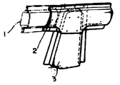
제2도는 외부패널의 사시도.2 is a perspective view of the outer panel.
제3도는 차체패널의 측면도.3 is a side view of the body panel.
제4도는 제3도의 I-I 선 확대단면도.4 is an enlarged sectional view taken along line I-I of FIG.
제5도는 제3도의 II-II 선 확대단면도.5 is an enlarged cross-sectional view taken along the line II-II of FIG.
제6도는 종래의 레인레일부의 사시도.6 is a perspective view of a conventional lane rail portion.
* 도면의 주요부분에 대한 부호의 설명* Explanation of symbols for main parts of the drawings
10 : 차체패널 11 : 프론트 필러부10: body panel 11: front pillar portion
12, 15 : 앞, 뒤 루우프 레일부 13 : 옆턱부12, 15: front and rear roof rail portion 13: side jaw portion
14 : 쿠오오터 필러부 16 : 외부패널14: Kuotor filler part 16: the outer panel
17, 18 : 앞,뒤외부 패널 17a, 18a : 앞, 뒤끝부분17, 18: front and rear outer panels 17a, 18a: front and rear ends
17b, 18b : 상,하끝부분(플랜지부) 19 : 센터필러부17b, 18b: upper and lower ends (flange portion) 19: center pillar portion
20 : 내부패널 22,22 : 앞, 뒤내부 패널20:
21a, 22a : 앞 뒤끝부분 21b, 22b : 상 ,하끝부분(플랜지부)21a, 22a: front and
21c : 연장부 21d : (연장부의)상, 하끝부분21c:
23 : 뒤 흙받이부23: fender back
본 발명은 자동차의 차체구조, 특히 루우프레일의 구조에 관한 것이다.The present invention relates to the structure of a vehicle body, in particular the structure of a rourail.
종래에, 자동차의 루우프레일의 구조로서는, 제6도에 나타내는 바와 같이, 외부패널(1)과 내부패널(2)로 패단면을 형성하도록 한 것이 제안되어 있다(일본국 실개소 55-22276 공보 참조). 또한 3은 필러이다.Conventionally, as a structure of the rougerail of an automobile, as shown in FIG. 6, what has been made to form the cut-out surface by the outer panel 1 and the
그런데, 루우프레일이 강도적으로 약하면, 충돌등의 때에 찌그러져서 실내공간이 좁혀진다는 문제가 있다.By the way, if the rourail is weak in strength, there is a problem that it collapses at the time of collision and the like and the indoor space is narrowed.
또한, 센터필터(3)에 시이트벨트앵커등이 부착되어 있는 경우, 벨트로부터의 하중이 필러(3)로 전달되어 루우프레일에 작용하여, 루우프레일이 안쪽(실내쪽)으로 변형한다는 문제가 있다.In addition, when a seat belt anchor or the like is attached to the center filter 3, the load from the belt is transmitted to the filler 3 and acts on the rouge frail, which causes the rouge filament to deform inward (indoor). .
이 때문에, 외부패널(1)과 내부패널(2)의 사이에 보강부재를 끼워 설치하여서 후우프레일을 보강하는 것이 고려되고 있지만, 별도의 부품이 필요하게 된다는 문제가 있다.For this reason, although it is considered to reinforce the huwoo frail by installing a reinforcing member between the outer panel 1 and the
본 발명은 상기한 종래의 문제를 해소하기 위하여 된 것으로서, 별도의 부품의 보강부재를 사용하는 일없이, 루우프레일을 간단하게 보강할 수 있도록 하는 것을 목적으로 하는 것이다.The present invention has been made in order to solve the above-mentioned conventional problems, and an object thereof is to enable easy reinforcement of the rouxrail without using a reinforcing member of a separate part.
본 발명은, 외부패널과 내부패널로 폐단면을 형성하는 자동차의 루우프레일에 있어서, 상기의 내부패널의 앞내부패널과, 뒤내부패널로 구성되며, 상기의 앞내부패널이 뒤끝에 루우프레일내에서 뒷방향으로 연장하는 연장부가 형성되며, 그 연장부의 상하끝부분은 상기의 뒤내부패널과 외부패널의 접합부에 접합되어서, 상기의 연장부에 의하여 루우프레일내에 2개의 폐단면이 형성된 것을 특징으로 하는 것이다.The present invention relates to a roof rail of an automobile in which a closed cross section is formed of an outer panel and an inner panel, wherein the front inner panel and the rear inner panel of the inner panel are formed, and the front inner panel is located in the rear rail at the rear end. Is formed extending in the rearward direction, the upper and lower ends of the extension are joined to the junction of the rear inner panel and the outer panel, characterized in that two closed end faces are formed in the rougerail by the extension. It is.
본 발명은, 앞뒤에 둘로 분할된 내부패널의 내에, 앞내부패널의 뒤끝을 연장하여, 그 연장부의 상하끝부분을 뒤내부패널과 외부패널의 접합부에 접합한 것이다.The present invention extends the rear end of the front inner panel in the inner panel divided into two front and rear, and joins the upper and lower ends of the extension to the joint portion of the rear inner panel and the outer panel.
따라서, 앞내부패널의 연장부에 의하여, 루우프레일내에 2개의 폐단면이 형성되게 하여 별도의 부품의 보강부재를 사용하지 않아도, 간단한 구조에 의하여 루우프레일이 보강하도록 한 것이다.Therefore, the extended portion of the front inner panel allows the two closed end surfaces to be formed in the roux foil so that the roux foil is reinforced by a simple structure without using a reinforcing member of a separate part.
이하, 본 발명의 실시예를 첨부한 도면에 기초하여 상세하게 설명한다.EMBODIMENT OF THE INVENTION Hereinafter, the Example of this invention is described in detail based on attached drawing.
제3도에 나타내는 바와 같이, 자동차의 차체옆부분의 패널(10)은, 프론트필러부(11)와 앞루우프레일부(12)와 옆턱부(13)(제2도 참조)를 갖춘 앞부분과 쿠오오터필러부(14)와 뒤루우프레일부(15)와 센터필러부(19)와 뒤흙받이부(23)를 갖춘 뒷부분으로 구성되어 있으며, 앞루우프레일부(12)의 뒤부분과, 뒤루우프레일부(15)의 앞부분 및 옆턱부(13)의 뒷부분으로 뒤흙받이부(23)의 앞부분이 접합되어서 구성되어 있다.As shown in FIG. 3, the
이와 같이 패널(10)을 앞부분과 뒤부분으로 분할하여 접합하는 것은, 생산성의 향상때문이다.Thus, the
따라서, 차체패널(10)의 외부패널(16)은, 제2도에 나타내는 바와 같이, 앞외부패널(17)와 뒤외부패널(18)로 구성되며, 앞외부패널(17)의 앞루우프레일(12)의 뒤끝부분(17a)과 뒤외부패널(18)의 뒤루우프레일부(15)의 앞끝부분(18a)과는 센터필러부(19)의 전방위치에 있어서 일체로 접합되어 있다.Therefore, the
그리고, 차체패널(10)의 내부패널(20)도, 제1도에 나타내는 바와 같이, 앞내부패널(21)과 뒤내부패널(22)로 구성되며, 앞내부패널(21)의 앞루우프레일부(12)의 뒤끝부분(21a)과 내부패널(22)의 뒤루우프레일부(15)의 앞끝부분(22a)과는 센터필러부(19)의 전방위치에 있어서 일체로 접합되어 있다.In addition, the
그리고, 차체패널(10)은, 기본적으로 제4도에 나타내는 바와 같이, 앞, 뒤내부패널(21),(22)의 상하끝부분(플랜지부)(21b),(22b)과 각 외부패널(17),(18)의 상하끝부분(플랜지부) (17b),(18b)이 일체로 접합되어서 구성된다.As shown in FIG. 4, the
상기의 앞내부패널(21)의 뒤끝부분(21a)에는 바깥쪽으로 굽혀져서 센터필러부(19)의 뒷방향위치까지 연장하는 연장부(21c)가 일체로 형성되어 있다.The rear end portion 21a of the front
그리고, 그 연장부(21c)로 상하끝부분(21d)은, 제5도에 나타낸 바와 같이, 뒤내부패널(22)의 상하부분(22b)과 뒤외부패널(18)의 상하끝부분(18b)의 사이에 끼워져 설치된 상태로, 각 상하끝부분(21d),(22b),(18b)이 일체로 접합되어 있다.As shown in FIG. 5, the upper and
이와 같이 구성된 본 발명은, 센터필러부(19)를 중심으로 하여, 그 앞뒤위치의 루우프레일부(12),(15)내에는 뒤내부패널(22)과 뒤외부패널(18)의 사이에, 앞내부패널(21)의 연장부(21c)로 된 보강부재가 끼워져 설치되어, 연장부(21c)와 두외부패널(18)의 사이에 2개의 폐단면을 형성하였으므로, 별도의 부품의 보강부재를사용하는 일없이, 루우프레일부(12,)15)을 보강할 수 있는 것이다.The present invention configured as described above has a
Claims (1)
Applications Claiming Priority (3)
| Application Number | Priority Date | Filing Date | Title |
|---|---|---|---|
| JP?62-274168 | 1987-10-29 | ||
| JP62-274168 | 1987-10-29 | ||
| JP62274168A JPH0671893B2 (en) | 1987-10-29 | 1987-10-29 | Car body structure |
Publications (2)
| Publication Number | Publication Date |
|---|---|
| KR890006472A KR890006472A (en) | 1989-06-13 |
| KR910007004B1 true KR910007004B1 (en) | 1991-09-14 |
Family
ID=17537983
Family Applications (1)
| Application Number | Title | Priority Date | Filing Date |
|---|---|---|---|
| KR1019880013801A KR910007004B1 (en) | 1987-10-29 | 1988-10-21 | Automobile roof rail structure |
Country Status (4)
| Country | Link |
|---|---|
| US (1) | US4938525A (en) |
| JP (1) | JPH0671893B2 (en) |
| KR (1) | KR910007004B1 (en) |
| DE (1) | DE3836808A1 (en) |
Families Citing this family (21)
| Publication number | Priority date | Publication date | Assignee | Title |
|---|---|---|---|---|
| SE502870C2 (en) * | 1991-11-26 | 1996-02-05 | Volvo Ab | Reinforcement beam, for example for vehicle body parts |
| AU685706B2 (en) * | 1995-07-31 | 1998-01-22 | Toyota Jidosha Kabushiki Kaisha | Collision energy absorbing structure of vehicle body upper portion of automobile |
| DE19531874C1 (en) * | 1995-08-30 | 1996-10-02 | Daimler Benz Ag | Side wall sub assembly |
| JP3637141B2 (en) | 1996-03-19 | 2005-04-13 | 富士重工業株式会社 | Side collision countermeasure structure for vehicle body |
| SE508527C2 (en) * | 1997-02-12 | 1998-10-12 | Saab Automobile | automotive Body |
| SE512010C2 (en) * | 1997-02-12 | 2000-01-10 | Saab Automobile | automotive Body |
| DE19730395C1 (en) * | 1997-07-16 | 1998-11-19 | Daimler Benz Ag | Vehicle bodywork hollow carriers |
| DE19745126C1 (en) * | 1997-10-13 | 1999-03-18 | Daimler Benz Ag | Roof for motor vehicle |
| DE19829832B4 (en) * | 1998-07-03 | 2008-03-27 | Volkswagen Ag | Body structure for a motor vehicle |
| DE19926141B4 (en) * | 1999-06-09 | 2007-11-08 | Volkswagen Ag | Roof profile reinforcing element |
| JP3428545B2 (en) * | 2000-01-07 | 2003-07-22 | 本田技研工業株式会社 | Body reinforcement structure |
| DE10011946A1 (en) | 2000-03-11 | 2001-09-13 | Opel Adam Ag | Connection between the roof and the side wall of a motor vehicle body |
| DE10116437B4 (en) * | 2001-04-02 | 2006-04-27 | Bayerische Motoren Werke Ag | Body of a vehicle |
| JP3861651B2 (en) * | 2001-10-12 | 2006-12-20 | 三菱自動車エンジニアリング株式会社 | Reinforcement structure of vehicle anchor mounting part |
| DE60232575D1 (en) * | 2002-01-16 | 2009-07-23 | Nissan Motor | Reinforcement construction for body frames of motor vehicles |
| US7293823B2 (en) * | 2005-11-16 | 2007-11-13 | Ford Global Technologies, Llc | Interlocked pillar and roof rail joint |
| JP4774976B2 (en) * | 2005-12-15 | 2011-09-21 | マツダ株式会社 | Rear body structure of the vehicle |
| US7364225B2 (en) * | 2005-12-15 | 2008-04-29 | Mazda Motor Corporation | Vehicle body structure |
| JP5316566B2 (en) * | 2011-02-25 | 2013-10-16 | マツダ株式会社 | Vehicle superstructure |
| DE102016001241A1 (en) * | 2016-02-04 | 2017-08-10 | GM Global Technology Operations LLC (n. d. Ges. d. Staates Delaware) | Structure node for a motor vehicle body |
| CN111003067A (en) * | 2019-12-05 | 2020-04-14 | 宁波吉利汽车研究开发有限公司 | Upper side beam reinforcing structure of automobile |
Family Cites Families (9)
| Publication number | Priority date | Publication date | Assignee | Title |
|---|---|---|---|---|
| US3724153A (en) * | 1971-01-19 | 1973-04-03 | Budd Co | Joint construction |
| DE2160537A1 (en) * | 1971-12-07 | 1973-06-14 | Daimler Benz Ag | MOTOR VEHICLE ROOFS, IN PARTICULAR OF PASSENGER VEHICLES |
| JPS54146321A (en) * | 1978-05-09 | 1979-11-15 | Mitsubishi Motors Corp | Panel construction for automobile |
| JPS5522276U (en) * | 1978-08-02 | 1980-02-13 | ||
| JPS5562472U (en) * | 1978-10-25 | 1980-04-28 | ||
| US4552400A (en) * | 1981-08-04 | 1985-11-12 | Mazda Motor Company | Two-door type automobile body structure |
| JPS5914579A (en) * | 1982-07-16 | 1984-01-25 | Nissan Motor Co Ltd | Reinforcing construction for transverse girder structural member in sliding door type vehicle |
| JPS60124574A (en) * | 1983-12-08 | 1985-07-03 | Mazda Motor Corp | Chassis structure |
| GB8718787D0 (en) * | 1987-08-07 | 1987-09-16 | Jaguar Cars | Vehicle door assembly |
-
1987
- 1987-10-29 JP JP62274168A patent/JPH0671893B2/en not_active Expired - Fee Related
-
1988
- 1988-10-21 KR KR1019880013801A patent/KR910007004B1/en not_active IP Right Cessation
- 1988-10-26 US US07/262,874 patent/US4938525A/en not_active Expired - Lifetime
- 1988-10-28 DE DE3836808A patent/DE3836808A1/en active Granted
Also Published As
| Publication number | Publication date |
|---|---|
| DE3836808C2 (en) | 1992-09-17 |
| KR890006472A (en) | 1989-06-13 |
| DE3836808A1 (en) | 1989-05-18 |
| US4938525A (en) | 1990-07-03 |
| JPH01115780A (en) | 1989-05-09 |
| JPH0671893B2 (en) | 1994-09-14 |
Similar Documents
| Publication | Publication Date | Title |
|---|---|---|
| KR910007004B1 (en) | Automobile roof rail structure | |
| JPH0345903Y2 (en) | ||
| KR960003508Y1 (en) | Vehicle upper structure | |
| JPH0723108B2 (en) | Rear body structure of automobile | |
| KR930005021B1 (en) | Rear body structure for automobile | |
| JPH0139393B2 (en) | ||
| JPH107021A (en) | Connection part structure of pillar and side sill of automobile | |
| JPH06144300A (en) | Floor tunnel reinforcing structure for automobile | |
| JPS6031973Y2 (en) | car body structure | |
| JPH01317850A (en) | Fitting structure for retractor device of seat belt | |
| JPS602996Y2 (en) | Vehicle center pillar seat belt mounting structure | |
| JPH05294257A (en) | Front body structure of automobile | |
| JP3362915B2 (en) | Car front body structure | |
| JPS6338140Y2 (en) | ||
| JPS6210216Y2 (en) | ||
| KR100242767B1 (en) | Connecting structure between center floor panel and side sill for a vehicle | |
| JPH0310975A (en) | Car body front construction | |
| JPH0621820Y2 (en) | Rear body structure of automobile | |
| JPH049270Y2 (en) | ||
| JPH0518232Y2 (en) | ||
| JPH0481367A (en) | Car body structure of automobile | |
| KR0118291Y1 (en) | The center pilar of a car body | |
| KR0120544Y1 (en) | The structure of roof side rail | |
| KR200205043Y1 (en) | Reinforcement structure of vehicle center cross member | |
| JPS6141668Y2 (en) |
Legal Events
| Date | Code | Title | Description |
|---|---|---|---|
| A201 | Request for examination | ||
| E902 | Notification of reason for refusal | ||
| G160 | Decision to publish patent application | ||
| E701 | Decision to grant or registration of patent right | ||
| GRNT | Written decision to grant | ||
| FPAY | Annual fee payment |
Payment date: 20010905 Year of fee payment: 11 |
|
| LAPS | Lapse due to unpaid annual fee |