KR900005832B1 - Arrangements for forming roof structures of vehicle bodies - Google Patents
Arrangements for forming roof structures of vehicle bodies Download PDFInfo
- Publication number
- KR900005832B1 KR900005832B1 KR1019870006089A KR870006089A KR900005832B1 KR 900005832 B1 KR900005832 B1 KR 900005832B1 KR 1019870006089 A KR1019870006089 A KR 1019870006089A KR 870006089 A KR870006089 A KR 870006089A KR 900005832 B1 KR900005832 B1 KR 900005832B1
- Authority
- KR
- South Korea
- Prior art keywords
- roof
- opening
- rail
- sulfur
- frame member
- Prior art date
Links
Images


Classifications
-
- B—PERFORMING OPERATIONS; TRANSPORTING
- B60—VEHICLES IN GENERAL
- B60J—WINDOWS, WINDSCREENS, NON-FIXED ROOFS, DOORS, OR SIMILAR DEVICES FOR VEHICLES; REMOVABLE EXTERNAL PROTECTIVE COVERINGS SPECIALLY ADAPTED FOR VEHICLES
- B60J7/00—Non-fixed roofs; Roofs with movable panels, e.g. rotary sunroofs
- B60J7/02—Non-fixed roofs; Roofs with movable panels, e.g. rotary sunroofs of sliding type, e.g. comprising guide shoes
- B60J7/06—Non-fixed roofs; Roofs with movable panels, e.g. rotary sunroofs of sliding type, e.g. comprising guide shoes with non-rigid element or elements
- B60J7/061—Non-fixed roofs; Roofs with movable panels, e.g. rotary sunroofs of sliding type, e.g. comprising guide shoes with non-rigid element or elements sliding and folding
- B60J7/064—Non-fixed roofs; Roofs with movable panels, e.g. rotary sunroofs of sliding type, e.g. comprising guide shoes with non-rigid element or elements sliding and folding using folding arms sliding in longitudinal tracks for supporting the soft roof
-
- B—PERFORMING OPERATIONS; TRANSPORTING
- B60—VEHICLES IN GENERAL
- B60J—WINDOWS, WINDSCREENS, NON-FIXED ROOFS, DOORS, OR SIMILAR DEVICES FOR VEHICLES; REMOVABLE EXTERNAL PROTECTIVE COVERINGS SPECIALLY ADAPTED FOR VEHICLES
- B60J7/00—Non-fixed roofs; Roofs with movable panels, e.g. rotary sunroofs
- B60J7/08—Non-fixed roofs; Roofs with movable panels, e.g. rotary sunroofs of non-sliding type, i.e. movable or removable roofs or panels, e.g. let-down tops or roofs capable of being easily detached or of assuming a collapsed or inoperative position
- B60J7/10—Non-fixed roofs; Roofs with movable panels, e.g. rotary sunroofs of non-sliding type, i.e. movable or removable roofs or panels, e.g. let-down tops or roofs capable of being easily detached or of assuming a collapsed or inoperative position readily detachable, e.g. tarpaulins with frames, or fastenings for tarpaulins
Abstract
Description
제1도는 본 발명의 실시예의 요부인 지붕의 골격의 사시도.1 is a perspective view of a skeleton of a roof which is a main part of an embodiment of the present invention.
제2도는 마찬가지로 앞쪽 및 뒤쪽의 지붕패널의 사시도.2 is a perspective view of the roof panel in the front and rear as well.
제3도는 마찬가지로 프레임부재를 부착한 지붕의 사시도.3 is a perspective view of the roof similarly to which the frame member is attached.
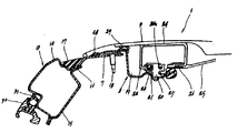
제4도는 마찬가지로 지붕개폐용 황부재를 부착한 지붕의 요부단면도.4 is a sectional view of the main part of the roof to which the yellow member for roof opening and closing is attached.
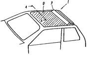
제5도는 종래예의 전체사시도.5 is an overall perspective view of a conventional example.
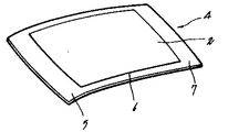
제6도는 종레예의 지붕패널의 사시도.6 is a perspective view of the roof panel of Jongleye.
제7도는 제5도의 A-A선 단면도.7 is a cross-sectional view taken along the line A-A of FIG.
* 도면의 주요부분에 대한 부호의 설명* Explanation of symbols for main parts of the drawings
1 : 지붕 2 : 개구부1: roof 2: opening
3 : 지붕개폐용 황부재 4 : 지붕패널3: roof member for roof opening 4: roof panel
5 : 앞쪽지붕패널 6 : 뒤쪽지붕패널5: front roof panel 6: rear roof panel
8 : 프레임부재 11 : 앞쪽헤더8 frame member 11 front header
12 : 뒤쪽헤더 13 : 지붕레일12: rear header 13: roof rail
16 : 접합플랜지부 22 : 접동부재16: joint flange 22: sliding member
본 발명은, 지붕개폐용 황부재(幌部材)를 갖춘 차량의 지붕구조에 관한 것이다. 상세하게는, 차량의 지붕구조에 있어서, 지붕에 형성된 개구부론 개폐 자재하게 덮는 지붕개폐용 황부재를 배설하는 지붕개폐용 황부재의 배설구조(配設構造)의 개량에 관한 것이다.TECHNICAL FIELD This invention relates to the roof structure of the vehicle provided with the sulfur member for roof opening and closing. Specifically, the present invention relates to an improvement in the excretion structure of the roof opening / closing sulfur member for disposing a roof opening / closing sulfur member, which is covered with the opening and closing material of the roof in a vehicle roof structure.
종래, 지붕에 개구부를 형성하여, 이 개구부를 개폐 자재한 지붕개폐용 황부재로 덮고, 지붕개폐용 황부재를 개방 조작함으로서 무개차와 같은 해방감을 얻도록 한 차량의 지붕구조가 개발되고 있다(예, 영국특허 제1315364호 명세서 참조). 이하 지붕개폐용 황부재를 간단히 "황부재"라 칭한다.Conventionally, a roof structure of a vehicle has been developed in which an opening is formed in a roof, the opening is covered with a roof opening / closing sulfur member which is opened and closed, and the roof opening / closing sulfur member is opened to obtain a feeling of openness such as a car. , British Patent No. 1315364). Hereinafter, the sulfur member for roof opening and closing is referred to simply as "sulfur member".
상기 차량의 지붕구조를 예를 들면, 제5도 내지 제7도에 의거해서 설명한다. 제5도의 전체사시도에 도시한 바와 같이, 지붕(1)의 개구부(2)에 황부재(3)가 착설되고, 이 황부재(3)가 통상시에는 사선으로 표시한 상태로 설정되어서 개구부(2)를 덮고, 무개차와 같은 해방감을 얻고 싶을 때에는, 도면에 표시한 상태로 설정되어서 개구부(2)를 개방하도록 구성되어 있다.The roof structure of the vehicle will be described based on, for example, FIGS. 5 to 7. As shown in the overall perspective view of FIG. 5, the sulfur member 3 is installed in the opening 2 of the roof 1, and the sulfur member 3 is normally set in the state indicated by the diagonal line so that the opening ( When 2) is covered and a feeling of openness such as a carriage is desired, the opening 2 is set in a state shown in the drawing.
상기 차량의 지붕구조에 있어서, 구성하는 지붕패널(4)은, 제6도에 도시한 바와 같이, 중앙에 개구부(2)가 형성되고, 앞쪽지붕패널(5), 뒤쪽지붕패널(6) 및 양쪽의 지붕패널(7)로 이루어진 것으로서, 프레스 성형에 의해서 일체적으로 형성되어 있다.In the roof structure of the vehicle, as shown in FIG. 6, the
또, 제6도에는 도시하지 않았으나, 상기 개구부(2)에는, 그 주연에 따라서 4각형인 프레임부재(8)가 배치되고, 이 프레임부재(8)에는, 상기 개구부(2)를 덮도록 황부재(3)가 안내 지지되나, 제7도에 의해 설명한다.Although not shown in FIG. 6, a quadrangular frame member 8 is disposed in the opening 2 along its periphery, and the frame member 8 is covered with sulfur to cover the opening 2. Although the member 3 is guide-supported, it demonstrates with FIG.
제7도는 황부재(3)가 개구부(2)를 덮고 있는 상태에 있어서의 제5도의 A-A선 단면도이며, (13)은 지붕레일로서, 지붕(1)의 측부에 앞뒤방향으로 뻗어있고, 바깥지붕레일(14)과 안지붕레일(15)을 폐단면 형상으로 접합한 것이며, 그 앞뒤단부가 앞필터, 뒤필터(도시하지 않음)등에 접합되어 있다. (16)은 바깥지붕레일(14)과 안지붕레일(15)의 상부 쪽의 접합부인 접합플랜지부이며, 이 접합플랜지부(16)에는 측(側)부 지붕패널(7)이 재치고정되고. 지붕레일(13)과 측부지붕패널(7)과의 접합부에 형성된 홈에는 지붕모울딩(roofmolding) (17)이 매워 넣어져서 방수 및 형상 조정되어 있다.FIG. 7 is a cross-sectional view taken along line AA of FIG. 5 in a state in which the sulfur member 3 covers the opening 2, and (13) is a roof rail, which extends in the front and rear directions on the side of the roof 1, and The roof rail 14 and the inner roof rail 15 are joined in a closed cross-sectional shape, and the front and rear ends thereof are joined to a front filter, a rear filter (not shown), and the like.
프레임부재(8)는, 측부지붕패널(7)의 개구부 주연에 걸어 맞추어지도록 착설되고, 최외측부가 클립 등의 고정부재(18)에 의해서 측부지붕패널(7)에 고정되어 있다. 프레임부재(8)에는 소정위치에 배수구멍(도시하지 않음)을 가진 레인레일(19) 및 안내홈(21)을 가진 안내레일(20)이 착설되어 있다.The frame member 8 is installed so as to be engaged with the periphery of the opening of the side roof panel 7, and the outermost side is fixed to the side roof panel 7 by fixing members 18, such as a clip. The frame member 8 is provided with a
상기 안내레일(20)에는, 황부재(3)에 착설된 복수개의 접동부재(22)가 앞뒤방향으로 이동할 수 있도록 착설되어 있다. 이 접동부재(22)는, 안내레일(20)의 안내홈(21)에 걸어 맞추어지는 굴림대, 슈우 등의 미끄럼부재(23), 황부재(3)를 고정 지지하는 지지부(24) 및 황부재(3)의 중간부를 지지하는 스테이(25)를 부착하는 부착부(26)를 구비하고 있다. 또, 황부재(3)는 도시하지 않는 구동장치에 의해, 안내레일(20)의 와이어 감합부(20a)에 삽감된 와이어(27)를 구동함으로서 앞뒤방향으로 이동된다.The guide rail 20 is installed so that the plurality of sliding members 22 mounted on the sulfur member 3 can move forward and backward. The sliding member 22 includes a sliding member 23 such as a roller, a shoe, etc., which is engaged with the guide groove 21 of the guide rail 20, a
황부재(3)는 가용성이 높고, 내수성, 내후성 등에 뛰어난 시이트 형성물이다(28),(29)는 방음, 방수를 위하여 프레임부재(8)의 주연에 착설된 시일부재이고, (31)은 도어의 새시(30)에 착설된 시일부재이다. 제5도 내지 제7도에 도시한 차량의 지붕구조에 있어서, 황부재(3)는 앞쪽지붕패널(5), 뒤쪽지붕패널(6), 양쪽의 측부지붕패널(7)로 둘러싸인 개구부(2)를 덮도록 배설되어 있으며, 와이어(27)를 구동함으로서 황부재(3)를 제5도에 표시한 위치로 이동시켜, 개구부(2)를 개방하고, 해방감을 조성할 수 있다.The sulfur member 3 is a sheet formation having high solubility and excellent in water resistance, weather resistance, etc. (28) and (29) are seal members installed on the periphery of the frame member (8) for soundproofing and waterproofing. It is a seal member mounted on the
그러나, 상기 구조의 경우 개구부(2)를 타발성형에 의하여 형성할 필요가 있기 때문에 필연적으로 상기 황부재에 의해서 개방되는 개구부(2)의 차폭치수가 좁아지기 때문에 개구부(2)의 면적이 작아져서, 충분한 해방감을 얻을 수 없으며, 또 프레스 성형 시에 앞뒤의 지붕패널(5),(6)사이에 비틀림이 발생하기 쉽고, 제조수율이 나쁘다. 또, 차량의 지붕에 착설할 때에도 상기 비틀림을 발생하기 쉽고, 조립 정밀도가 나아지는 등의 문제점이 있다.However, in the case of the above structure, since the opening 2 needs to be formed by punch molding, the area of the opening 2 becomes small because the difference in the width of the opening 2 that is opened by the sulfur member is inevitably narrowed. In addition, sufficient openness cannot be obtained, and torsion is likely to occur between the front and back roof panels 5 and 6 during press molding, and the production yield is poor. In addition, there is a problem in that the torsion is liable to occur even when installed on the roof of the vehicle, and the assembly accuracy is improved.
본 발명은, 상기 종래의 문제점을 해소하기 위하여 이루어진 것으로서, 그 목적은, 개구부 면적을 크게함으로서, 보다 충실한 해방감을 얻을 수 있고, 또한 지붕의 제조수율의 향상을 도모함과 동시에 지붕의 조립정밀도를 향상시킬 수 있는 차량의 지붕개폐용 황부재의 배설구조를 제공하는데 있다.SUMMARY OF THE INVENTION The present invention has been made to solve the above-mentioned conventional problems. The object of the present invention is to increase the opening area, thereby to achieve a more open feeling, and to improve the manufacturing yield of the roof and to improve the assembly accuracy of the roof. It is to provide an excavation structure of the sulfur member for opening and closing the roof of the vehicle that can be made.
본 발명은, 상기 목적을 달성하기 위하여 종래와 같이 개구부가 형성된 지붕패널을 사용함이 없이, 별체로 형성된 앞쪽지붕패널과 뒤쪽지붕패널을 사용하고, 앞쪽 및 뒤쪽의 지붕패널과 양쪽의 지붕레일로 개구부를 형성하고, 이 개구부에 황부재를 배설하여 차량의 지붕개폐용 황부재의 배설구조를 구성한 것이다.In order to achieve the above object, the present invention uses a front roof panel and a rear roof panel formed separately, without using a roof panel having openings as in the prior art, and opens the roof panels at the front and rear sides and roof roofs at both sides. And the sulfur member is disposed in the opening to form an excretion structure of the sulfur member for roof opening and closing of the vehicle.
즉, 본 발명은 지붕에 개구부를 형성차고, 이 개구부를 개폐 자제하게 덮는 황부재가 배치된 차량의 지붕구조이며, 지붕의 앞쪽과 뒤쪽에 소정간격을 두고서 착설되고, 상기 개구부의 앞가장자리부와 뒤가장자리부를 형성하는 앞속지붕패널 및 뒤쪽지붕패널과, 지붕의 양쪽에 앞뒤방향으로 연재되어 상기 개구부의 옆가장자리부를 형성하는 지붕레일과, 상기 개구부의 주연에 따라서 배치되고, 측단부가 상기 지붕레일에 재치 고정된 4각형상의 프레임부재와, 이 프레임부재의 상기 양쪽의 지붕레일에 따른 각각의 부분에 착설된 안내레일과, 복수개의 접동부재가 배설되고, 또한 상기 복수개의 접동부재가 상기 안내레일에 걸어맞추어지도록 배치된 황부재를 구비하고 있는 것을 특징으로 하는 것이다.That is, the present invention is a roof structure of a vehicle having an opening formed in the roof, and a sulfur member disposed to cover the opening and closing, and installed at a predetermined interval in front and the rear of the roof, and the front edge of the opening and A front roof panel and a rear roof panel forming a rear edge portion, a roof rail extending back and forth on both sides of the roof to form a side edge portion of the opening, and a side end portion is disposed along the periphery of the opening portion A quadrangular frame member mounted on the seat, a guide rail mounted on each part of the roof rails on both sides of the frame member, a plurality of sliding members are disposed, and the plurality of sliding members are provided on the guide rails. It is characterized in that it comprises a sulfur member arranged to be engaged with.
이하에, 본 발명의 실시예를 제1도 내지 제4도에 의거해서 설명한다. 또한, 제1도 내지 제4도에 있어서, 제5도 내지 제7도에 도시한 부호와 동일한 부호는 동일한 기능부재를 의미한다.EMBODIMENT OF THE INVENTION Below, the Example of this invention is described based on FIG. 1 thru | or FIG. In addition, in FIG. 1 thru | or FIG. 4, the code | symbol same as the code | symbol shown in FIG. 5 thru | or 7 means the same functional member.
제1도는 지붕의 좌우의 중심선에서 절단한 지붕의 골격을 사시도로 도시한 것이며, 지붕레일(13)은, 제4도에 상세하게 도시한 바와 같이 바깥지붕레일(14)과 안지붕레일(13)이 폐단면 형상으로 접합되고, 그 상부쪽의 접합부인 접합플랜지부(16)가 수평형상으로 형성되어 있다. 지불레일(13)의 접합플랜지부(16)에는 앞쪽지붕패널(5) 및 뒤쪽지붕패널(6)의 양쪽단부가 접합되고, 앞쪽 및 뒤쪽의 헤더(11),(12)에 의해서 지붕앞뒤쪽의 골격(9),(10)이 형성되고, 또 상기 각 부재에 둘러싸여서 개구부(2)가 형성되어 있다.FIG. 1 is a perspective view showing a skeleton of a roof cut from the left and right center lines of the roof, and the roof rail 13 is an outer roof rail 14 and an inner roof rail 13 as shown in detail in FIG. ) Is joined in a closed cross-sectional shape, and a joining
제2도는, 앞쪽 및 뒤쪽지붕패널(5),(6)을 제1도와 대응해서 사시도로 도시한 것이며, 앞쪽지붕패널(5)및 뒤쪽지붕패널(6)은, 각각 별체로 프레스 성형된 것이다. 각 지붕패널(5),(6)은 제1도에서 설명한 바와 같이, 각각에 대응한 헤더(11),(12)에 접합됨과 동시에, 그 양쪽단부가 지붕레일(13)의 접합플랜지부(16)에 접합된다.2 is a perspective view of the front and rear roof panels 5 and 6 corresponding to the first view, and the front roof panel 5 and the rear roof panel 6 are separately press-molded. . As described in FIG. 1, each roof panel 5, 6 is joined to the
제3도는 좌우의 중심선에서 절단한 지붕을 사시도로 도시한 것이며, 이 지붕은, 제1도에 도시한 지붕의 개구부(2)에 따라서 프레임부재(8)를 부착한 것이다. 프레임부재(8)는, 양쪽의 지붕레일(13)과 앞쪽 및 뒤쪽의 지붕패널(5),(6)(또는 헤더)로 형성된 개구부(2)의 주연에 따라서 배치되고, 클립 등의 고정부재(도시하지 않음)에 의해서 각각에 고정되어 있다. 또한, 앞쪽 및 뒤쪽의 지붕패널(5),(6)과 지붕레일과의 접합부에 형성된 홈에는, 지붕모울딩(17)이 메워넣어져 있다.FIG. 3 is a perspective view of the roof cut from the left and right center lines, and the roof is attached with the frame member 8 along the opening 2 of the roof shown in FIG. The frame member 8 is arranged along the periphery of the roof rails 13 on both sides and the openings 2 formed by the front and rear roof panels 5 and 6 (or headers), and fastening members such as clips. It is fixed to each by (not shown). In addition, the
제4도는, 제3도에 도시한 지붕의 프레임부재(8)에 황부재(3)를 정착한 상태의 요부단면도이며, 지붕레일(13)과 프레임부재(8) 및 황부재(3)와의 관계를 표시한다. 프레임부재(8)는, 단면이 대략 형상으로 형성되고, 차체고정부인 최외측부가 지붕레일(13)의 꼭대기부에 재치되어서 클립 등의 고정부재(18)에 의해서 고정되고, 레인레일(19)을 형성한 부분이 지붕레일(13)의 접합플랜지부(16)에 재치되어 있다.FIG. 4 is a sectional view of the main parts of the state in which the sulfur member 3 is fixed to the frame member 8 of the roof shown in FIG. 3, and the roof rail 13 and the frame member 8 and the sulfur member 3 are separated from each other. Display the relationship. The frame member 8 is formed in a substantially cross section, and the outermost part, which is the vehicle body fixing part, is placed on the top of the roof rail 13 to be fixed by fixing members 18 such as clips, and the
황부재(3)는 프레임부재(8)의 레인레일(19)보다 안쪽에 착설된 안내레일(20)과 황부재(3)쪽에 배설된 복수개의 접동부재(22)에 의해서 지지되어 있으며, 도시하지 않는 구동장치에 의해 와이어(27)를 구동함으로서 앞뒤방향으로 이동된다.The sulfur member 3 is supported by the guide rail 20 installed inside the
본 실시예의 차량의 지붕개폐용 황부재의 배설구조는, 이상의 각 도면에 있어서 설명한 바와 같이, 앞쪽 및 뒤쪽의 지붕패널(5),(6)자 양쪽의 지붕레일(13)에 의해서 형성된 개구부(2)에 프레임부재(8)를 배치 고정하고, 이 프레임부재(8)에 황부재(3)를 이동 가능하게 배설한 것으로서, 개구부의 측연부가 앙쪽의 지붕레일(13)에 의해서 형성되어 있기 때문에, 차폭 치수가 넓은 개구부를 형성할 수 있었다.The excavation structure of the roof opening / closing sulfur member of the vehicle according to the present embodiment includes the openings formed by the roof rails 13 on both the front and rear roof panels 5 and 6 as described in the above drawings. The frame member 8 is fixedly disposed at 2), and the sulfur member 3 is disposed on the frame member 8 so as to be movable. The side edges of the openings are formed by the roof rails 13 on the side. The opening having a wide vehicle width dimension could be formed.
또, 프레임부재(8)의 차체고정부인 최외측부가 지붕레일(13)의 꼭대기부에 재치되어 있기 때문에, 앞쪽지붕패널(5),(6)과 지붕레일(13)의 접합부에 형성되는 홈이 지붕레일(13)에 있어서의 앞 뒤쪽의 일부분만으로 되어, 종래와 같이 지붕레일(13)의 전체길이에 걸쳐서 지붕모울딩을 할 필요가 없어, 지붕모울딩의 사용량을 크게 줄일 수 있다.In addition, since the outermost part of the frame member 8, which is the vehicle body fixing part, is placed at the top of the roof rail 13, a groove formed at the junction of the front roof panels 5, 6 and the roof rail 13 is formed. Since only a part of the front and rear of the roof rail 13 is used, it is not necessary to perform roof molding over the entire length of the roof rail 13 as in the prior art, and the usage of the roof molding can be greatly reduced.
또, 프레임부재(8)의 레인레일(19)의 부분이 지붕레일(13)의 접합플랜지부(16)에 재치되어 있기 때문에, 프레임부재(8)는 안정적으로 지지된다.Moreover, since the part of the
본 발명의 지붕개폐용 황부재의 배설구조는 지붕의 개구부가 앞쪽 및 뒤쪽의 지붕패널과 양쪽의 지붕레일로 형성되어 있기 때문에, 종래의 것과 비교해서 차폭수지가 넓은 개구부를 얻을 수 있어, 황부재로 개방할 수 있는 개구면적이 증가하여, 보다 높은 해방감을 얻을 수 있다.In the structure of the roof opening / closing sulfur member of the present invention, since the openings of the roof are formed of the front and rear roof panels and both roof rails, the openings having a wider width difference width resin can be obtained as compared with the conventional ones. The opening area which can be opened by increases, and a higher release feeling can be obtained.
또, 지붕패널에 대해서 타발성형에 의해 개구부를 형성할 필요가 없으며, 사용되는 지붕패널은 앞폭과 뒤쪽의 지붕패널만으로 되고 또한 각각이 따로따로 프레스 성형되는 것이기 때문에, 종래와 같이 제조 중 또는 조립 중에 비틀림을 발생하는 일이 없어, 제조수율이 향상하는 동시에 조립작업을 효율 좋게 실시할 수 있다.In addition, it is not necessary to form the opening part by punch molding with respect to the roof panel, and since the roof panel used is only the front panel of the front width | variety and the back, and each is press-molded separately, it is during manufacture or assembly as before. No torsion occurs, the production yield can be improved, and the assembly work can be performed efficiently.
또, 종래와 같이 타발에 의해서 발생하는 재료의 낭비가 적고, 지붕패널의 재료의 절약을 도모할 수 있다.In addition, waste of material generated by punching is reduced as in the prior art, and the material of the roof panel can be saved.
Claims (1)
Applications Claiming Priority (3)
| Application Number | Priority Date | Filing Date | Title |
|---|---|---|---|
| JP61141014A JPS62295720A (en) | 1986-06-16 | 1986-06-16 | Canvas stop arrangement structure for vehicle |
| JP141014 | 1986-06-16 | ||
| JP61-141014 | 1986-06-16 |
Publications (2)
| Publication Number | Publication Date |
|---|---|
| KR880000263A KR880000263A (en) | 1988-03-24 |
| KR900005832B1 true KR900005832B1 (en) | 1990-08-13 |
Family
ID=15282187
Family Applications (1)
| Application Number | Title | Priority Date | Filing Date |
|---|---|---|---|
| KR1019870006089A KR900005832B1 (en) | 1986-06-16 | 1987-06-16 | Arrangements for forming roof structures of vehicle bodies |
Country Status (3)
| Country | Link |
|---|---|
| US (1) | US4838607A (en) |
| JP (1) | JPS62295720A (en) |
| KR (1) | KR900005832B1 (en) |
Cited By (1)
| Publication number | Priority date | Publication date | Assignee | Title |
|---|---|---|---|---|
| KR101866515B1 (en) * | 2017-09-20 | 2018-07-23 | (주)에이티이기술 | Matrix Switching System And Method For Controling The Same |
Families Citing this family (9)
| Publication number | Priority date | Publication date | Assignee | Title |
|---|---|---|---|---|
| JPH0370627A (en) * | 1989-08-11 | 1991-03-26 | Mazda Motor Corp | Slide roof device for vehicle |
| JP2543208B2 (en) * | 1989-11-29 | 1996-10-16 | マツダ株式会社 | Vehicle canvas top structure |
| DE19939725C2 (en) * | 1999-08-21 | 2002-05-29 | Webasto Vehicle Sys Int Gmbh | Vehicle convertible roof structure |
| US6406090B1 (en) * | 1999-09-20 | 2002-06-18 | Meritor Light Vehicle Systems, Inc. | Self-powered solar sunroof |
| JP4284793B2 (en) * | 1999-11-17 | 2009-06-24 | マツダ株式会社 | Upper body structure of the vehicle |
| US8458959B2 (en) * | 2007-03-30 | 2013-06-11 | Shiroki Corporation | Vehicle door frame structure |
| US7914072B2 (en) * | 2008-07-29 | 2011-03-29 | Ford Global Technologies, Llc | Moon roof frame module for reinforcement of automotive roof |
| FR2979292A1 (en) * | 2011-08-29 | 2013-03-01 | Peugeot Citroen Automobiles Sa | Device for forming convertible roof that is placed between two side parts of vehicle, has covers laterally extending bonnet into vehicle interior, where covers and assembly are visually arranged between bonnet and side parts of vehicle |
| KR20150069262A (en) * | 2013-12-13 | 2015-06-23 | 현대자동차주식회사 | Apparatus for preventing droop of blind for panorama sunroof |
Family Cites Families (8)
| Publication number | Priority date | Publication date | Assignee | Title |
|---|---|---|---|---|
| GB167583A (en) * | 1920-05-11 | 1921-08-11 | Charles Edmund Peczenik | Improvements in or relating to vehicle-bodies and roofs |
| GB297408A (en) * | 1927-06-22 | 1928-09-24 | Donald Ashmore Pearson | Improvements in or relating to motor vehicle bodies |
| GB315346A (en) * | 1928-07-12 | 1929-10-24 | Karl Robert Wagner | Improvements in and relating to cases for bottles |
| GB334091A (en) * | 1929-10-03 | 1930-08-28 | Sunsaloon Bodies Ltd | Improvements in or relating to convertible saloon bodies for motor vehicles |
| GB339805A (en) * | 1929-12-21 | 1930-12-18 | Sunsaloon Bodies Ltd | Improvements in or relating to removable heads and roofs for motor vehicles |
| US1950371A (en) * | 1931-11-28 | 1934-03-06 | Baier Wilhelm | Sliding roof for motor vehicles |
| FR2053488A5 (en) * | 1969-07-07 | 1971-04-16 | Peugeot & Renault | |
| JPS6047126B2 (en) * | 1980-08-29 | 1985-10-19 | 日産自動車株式会社 | vehicle roof structure |
-
1986
- 1986-06-16 JP JP61141014A patent/JPS62295720A/en active Granted
-
1987
- 1987-06-11 US US07/060,401 patent/US4838607A/en not_active Expired - Fee Related
- 1987-06-16 KR KR1019870006089A patent/KR900005832B1/en not_active IP Right Cessation
Cited By (1)
| Publication number | Priority date | Publication date | Assignee | Title |
|---|---|---|---|---|
| KR101866515B1 (en) * | 2017-09-20 | 2018-07-23 | (주)에이티이기술 | Matrix Switching System And Method For Controling The Same |
Also Published As
| Publication number | Publication date |
|---|---|
| KR880000263A (en) | 1988-03-24 |
| JPS62295720A (en) | 1987-12-23 |
| JPH0445375B2 (en) | 1992-07-24 |
| US4838607A (en) | 1989-06-13 |
Similar Documents
| Publication | Publication Date | Title |
|---|---|---|
| KR900005832B1 (en) | Arrangements for forming roof structures of vehicle bodies | |
| JPH04212623A (en) | Frame for car slide roof or slide tilt roof | |
| JP3229080B2 (en) | Sliding roof device | |
| US20090064594A1 (en) | Structure of Window Opening of Car Door | |
| JPH02225130A (en) | Sunshine roof construction of automobile | |
| JPH04108031A (en) | Wind molding for vehicle | |
| JPS6238854Y2 (en) | ||
| JPS5822819Y2 (en) | Body structure of sliding groove mounting part | |
| JP3378323B2 (en) | Frame unit for vehicle roof | |
| JPS63222923A (en) | Guide rail structure for sun roof | |
| JPH0840076A (en) | Sunroof frame structure of sunroof | |
| JPS6315166B2 (en) | ||
| JP3251181B2 (en) | Convertible car seal structure | |
| JP3681552B2 (en) | Rear drainage groove mounting structure | |
| JPS63222925A (en) | Sun roof frame structure for sun roof | |
| JPH0111592Y2 (en) | ||
| JPH0126502Y2 (en) | ||
| JPS6332546Y2 (en) | ||
| JPH10119585A (en) | Drain structure for open car | |
| JPH06297955A (en) | Automobile door structure | |
| JPH077229Y2 (en) | Vehicle seal structure | |
| JP2605325Y2 (en) | Sunroof frame structure | |
| JPH0519218Y2 (en) | ||
| JP2560599Y2 (en) | Sunroof sunshade support device | |
| JP2560038Y2 (en) | Sunroof car roof structure and vehicle roof molding mounting structure |
Legal Events
| Date | Code | Title | Description |
|---|---|---|---|
| A201 | Request for examination | ||
| E902 | Notification of reason for refusal | ||
| G160 | Decision to publish patent application | ||
| E701 | Decision to grant or registration of patent right | ||
| GRNT | Written decision to grant | ||
| FPAY | Annual fee payment |
Payment date: 19950809 Year of fee payment: 6 |
|
| LAPS | Lapse due to unpaid annual fee |