KR900002478B1 - Method of high-speed rotation arc automatic fillet welding - Google Patents
Method of high-speed rotation arc automatic fillet welding Download PDFInfo
- Publication number
- KR900002478B1 KR900002478B1 KR1019860003100A KR860003100A KR900002478B1 KR 900002478 B1 KR900002478 B1 KR 900002478B1 KR 1019860003100 A KR1019860003100 A KR 1019860003100A KR 860003100 A KR860003100 A KR 860003100A KR 900002478 B1 KR900002478 B1 KR 900002478B1
- Authority
- KR
- South Korea
- Prior art keywords
- welding
- arc
- speed
- wire
- nozzle
- Prior art date
Links
Images


Classifications
-
- B—PERFORMING OPERATIONS; TRANSPORTING
- B23—MACHINE TOOLS; METAL-WORKING NOT OTHERWISE PROVIDED FOR
- B23K—SOLDERING OR UNSOLDERING; WELDING; CLADDING OR PLATING BY SOLDERING OR WELDING; CUTTING BY APPLYING HEAT LOCALLY, e.g. FLAME CUTTING; WORKING BY LASER BEAM
- B23K9/00—Arc welding or cutting
- B23K9/16—Arc welding or cutting making use of shielding gas
-
- B—PERFORMING OPERATIONS; TRANSPORTING
- B23—MACHINE TOOLS; METAL-WORKING NOT OTHERWISE PROVIDED FOR
- B23K—SOLDERING OR UNSOLDERING; WELDING; CLADDING OR PLATING BY SOLDERING OR WELDING; CUTTING BY APPLYING HEAT LOCALLY, e.g. FLAME CUTTING; WORKING BY LASER BEAM
- B23K9/00—Arc welding or cutting
- B23K9/02—Seam welding; Backing means; Inserts
- B23K9/0216—Seam profiling, e.g. weaving, multilayer
Landscapes
- Engineering & Computer Science (AREA)
- Physics & Mathematics (AREA)
- Plasma & Fusion (AREA)
- Mechanical Engineering (AREA)
- Butt Welding And Welding Of Specific Article (AREA)
- Arc Welding In General (AREA)
Abstract
Description
제 1 도는 비이드의 기울기를 표시하는 기울기 상태도.1 is a tilt state diagram showing the tilt of the bead.
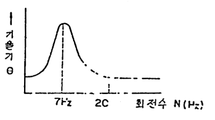
제 2 도는 회전수와 기울기의 특성도.2 is a characteristic diagram of rotational speed and tilt.
제 3 도는 본 발명의 실시예의 개략 구성도.3 is a schematic structural diagram of an embodiment of the present invention.
제 4 도는 회전수와 다리길이의 비율 l1/l2의 특성도.4 is a characteristic diagram of the ratio of rotational speed to leg length l 1 / l 2 .
제 5 도는 아아크 회전직경과 다리길이의 비율 l1/l2의 특성도.5 is a characteristic diagram of the ratio l 1 / l 2 of arc rotation diameter and leg length.
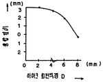
제 6 도는 아아크 회전직경과 융합깊이의 특성도.6 is a characteristic diagram of arc rotation diameter and fusion depth.
* 도면의 주요부분에 대한 부호의 설명* Explanation of symbols for main parts of the drawings
1 : 밑판 2,2a : 세운판1:
3 : 와이어 4 : 비이드3: wire 4: bead
5 : 전극노즐 l1: 세운판 다리길이5: electrode nozzle l 1 : length of bridge
l2: 밀판 다리길이l 2 : Leg length
본 발명은 고속회전 아아크 필릿(fillet ; 구석살)의 자동 용접방법에 관한 것이다.The present invention relates to a method for automatic welding of high speed arc fillets.
종래에는 밑판에 세우는 세운판의 필릿의 용접은, 하향(下向) 수평자세로 이은 부분에 따라 용접을 진행시켜서 구석부분의 용접을 행하고 있다.Conventionally, the welding of the fillet of the upright plate mounted on the base board is welding the corner part by advancing welding along the part which connected to the downward horizontal posture.
상기와 같은 하향 수평자세의 필릿용접에서는 중력의 영향을 받아서 비이드(bead)가 밑판측에 늘어지기 쉽고, 같은 다리길이의 비이드를 얻기가 힘들며, 또한, 세운판에 언더커드(under cut)가 발생하기 쉽다는 등의 근본적인 문제가 있고, 특히, 고속도 용접에 의한 작은 다리길이의 비이드형성 혹은 그와 반대로 고전류로 저속용접에 의한 큰 다리길이의 비이드형성에도 문제가 있었다.In the fillet welding in the horizontal direction as described above, the bead tends to hang on the bottom plate side under the influence of gravity, and it is difficult to obtain the beads of the same leg length, and also the under cut on the upright plate. There is a fundamental problem such as that is easily generated, and in particular, there is a problem in the formation of beads of small legs length by high speed welding or the formation of beads of large legs length by low speed welding at high current and vice versa.
본 발명은 그러한 문제점을 해결하기 위하여 된 것으로서, 필릿용접의 동등한 다리길이화, 고속도화, 시공 다리길이 범위의 확대를 도모할 수가 있는 고속회전 아아크 필릿 자동용접 방법을 제안하는 것을 목적으로하는 것이다.The present invention has been made to solve such a problem, and an object of the present invention is to propose a high-speed rotating arc fillet automatic welding method capable of achieving an equivalent leg length, high speed, and expansion of a construction leg length range.
본 발명에 관한 고속회전 아아크 필릿 자동용접은, (가) 전극(電極)노즐을 동심상으로 회전하는 것에 의하여 이 노즐을 통과하는 와이어 선단을 회전시켜서 아아크를 고속 회전하고, (나) 용접 진행방향을 향하여 우측에 세운판을 배치하였을 때에는 상기 아아크의 회전방향을 전극노즐 상방으로부터 보아서 우회전(시계방향 회전)으로 하고, 용접 진행방향을 향하여 좌측에 세운판을 배치하였을 때에는 아아크의 회전방향을 전극노즐 상방으로부터 보아서 좌회전(반시계 방향)으로 하고, (다)의 상기 아아크의 회전속도는 세운판 다리길이와 밑판 다리길이의 비율이 최대가 되는 회전속도로 하고, (라) 상기 아아크의 회전직경은 1mm로부터 6mm로 하고, (마) 상기 회전하는 와이어는 직경 0.8mm로부터 1.6mm의 와이어를 사용하고, 가스시일드 아아크 용접 혹은 서브머어지드 아아크 용접에 의하여 하향 수평 필릿용접을 행하는 용접 방법이다.In the high-speed rotation arc fillet automatic welding according to the present invention, (a) by rotating the electrode nozzle concentrically, the tip of the wire passing through the nozzle is rotated to rotate the arc at high speed, and (b) the welding advancing direction. When the upright plate is placed on the right side, the arc direction is rotated to the right (clockwise rotation) from the upper side of the electrode nozzle. (A) The rotational speed of the arc in (c) is the rotational speed at which the ratio of the upright leg length and the bottom leg length is maximum, and (d) the rotation diameter of the arc is 1 mm to 6 mm, and (e) the rotating wire uses a wire of 0.8 mm to 1.6 mm in diameter, and is used for gas shield arc welding or By probe meoeo azide arc welding is a welding method for performing a down-horizontal fillet welding.
본 발명에 있어서는 필릿용접을 회전방향, 회전속도 및 회전직경을 한정한 고속회전 아아크에 의하여 행하는 것에 의하여 비이드의 아래에 늘어지기를 방지하고 동등한 다리길이로 하는 동시에 적정한 융합깊이로 양호한 필릿용접을 행한다.In the present invention, the fillet welding is performed by a high-speed rotating arc that defines the rotational direction, the rotational speed, and the rotational diameter to prevent sagging under the bead, to make an equivalent leg length, and to provide a good fillet welding with an appropriate fusion depth. Do it.
본 발명의 고속회전 아아크 필릿 자동용접 방법에 있어서, 아아크를 고속회전 아아크로 한 것은, 회전하지 않은 종래의 필릿용접에서는 비이드가 중력의 영향을 받아서 밑판측에 내려 앉지만, 이것을 방지하기 위하여 비이드에 세운판측에 편향(偏向)하는 힘을 주어서 동등한 다리길이의 비이드를 얻기 위하여서이다.In the high-speed rotating arc fillet automatic welding method of the present invention, the arc is made into a high-speed rotating arc, but in the conventional fillet welding without rotation, the beads fall down on the side of the bottom plate under the influence of gravity, This is to obtain a bead of equal leg length by giving a biasing force to the plate standing on the id.
예를들면, 용접전류 I=300A, 용접속도 V=22cm/분으로 아아크를 회전시키면서 좁은 베버링(beveling)용접에 의하여 비이드의 기울기를 조사한 결과, 비이드의 수평면에 대한 기울기 (θ)는 제 1 도에 표시한 것 같이 되었다.For example, as a result of investigating the inclination of the bead by narrow beveling welding while rotating the arc with welding current I = 300A and welding speed V = 22cm / min, the inclination (θ) of the bead with respect to the horizontal plane is It became as shown in FIG.
제 1 도에 있어서, (1)은 밑판, (2),(2a)는 세운판, (3)은 상방으로부터 보아서 우회전, 즉, 시계방향으로 회전하는 와이어, (4)는 비이드이다. 도면에 있어서, 비이드(4)는 용접이 지면의 뒷쪽에 진행하였을 때에 형성된 것을 표시한다.In FIG. 1, (1) is a bottom plate, (2) and (2a) are upright plates, (3) is a wire which rotates clockwise from right upward, that is, clockwise rotation, and (4) is a bead. In the figure, the
도면에 표시한 바와같이, 와이어(3)의 회전방향 및 용접진행 방향에 의하여 비이드(4)의 기울기에 큰 차가 보여지고, 와이어(3)가 우회전시는 용접 진행방향을 향하여 우로 올라간 비이드(4)로 되어 있다. 이 비이드(4)의 기울기(θ)는 아아크의 회전수(N)와 관계가 있고, 가로축에 회전수(N(Hz)), 세로축에 기울기(θ)를 표시하면, 제 2 도에 표시한 바와 같이 되어, 용접전류 I=300A, 용접속도 V=22cm/분일때는 아아크의 회전수(N)가 7Hz(420회전/분)일 때에 기울기(θ)가 최대로 되었다.As shown in the figure, a large difference in the inclination of the
그래서, 이 회전 아아크 용접을 제 3 도에 표시한 하향 수평 필릿용접에 의하여 전극노즐(5)을 회전하면서 밑판(1)과 세운판(2)의 구석부분을 용접하면, 비이드(4)의 기울기(θ)를 최대로 하는 아아크의 회전수(N)일때의 동등한 다리길이의 비이드가 얻기 쉽고, 필릿용접의 비이드형상의 개선을 도모할 수가 있다.Therefore, when the corner portion of the
이 동등한 다리길이의 비이드가 얻기 쉬운 적정회전수(No)를 용접전류(I)와 용접속도(V)를 변경하여 조사한 결과를 제 1 표에 표시한다.Table 1 shows the results obtained by changing the welding current (I) and the welding speed (V) to an appropriate rotational speed (No) that is easily obtained by the beads having the same leg length.
[표 1]TABLE 1

제 1 표로부터 명백한 바와같이, 적정회전수(No)는 용접 전류(I)와 용접속도(V)의 값에 의존하고, 이 비(比)) V/I가 증가하면 적정회전수(No)도 증가하는 경향을 가진다. 이 때문에 적정회전수(No)는 사용하는 용접전류(I), 용접속도(V)에 의하여 다르지만, 용접전류(I), 용접속도(V)를 정하면 적정회전수(No)가 정해진다.As apparent from the first table, the proper rotation speed No depends on the value of the welding current I and the welding speed V, and if the ratio V / I increases, the proper rotation speed No It also tends to increase. For this reason, although the proper rotation speed No changes with welding current I and welding speed V used, when the welding current I and welding speed V are determined, the appropriate rotation speed No will be determined.
이 적정회전수(No)를 정하는데는 사용하는 용접전류(I), 용접속도(V)로서 필릿용접을 행하고, 세운판(2)의 다리길이(l1)와 밑판(1)의 다리길이(l2)의 비(比) l1/l2가 최대로 되는 회전수를 구하면 된다.In order to determine the proper rotational speed (No), fillet welding is performed using the welding current (I) and the welding speed (V) to be used, and the leg length (l 1 ) of the upright plate (2) and the leg length of the base plate ( the ratio (比) l 1 / l 2 l of 2) is Obtaining a rotation speed becomes maximum.
제 4 도는 용접전류 I=300A, 용접속도 V=22cm/분일때의 아아크 회전수와 다리길이의 비 l1/l2와의 관계를 표시하고, 도시된 바와같이, 이 용접 조건일때의 적정회전수(No)는 7Hz(420회전/분)로 된다.4 shows the relationship between the arc speed at the welding current I = 300A, the welding speed V = 22cm / min, and the ratio l 1 / l 2 of the leg length, and as shown, the proper rotation speed at this welding condition. No is set to 7 Hz (420 revolutions per minute).
한편, 이 다리길이의 비 l1/l2의 최대치는 용접전류(I), 용접속도(V)가 일정하여도 아아크의 회전직경(D)에 의하여 상이하다. 예를들면, 용접전류 I=300A, 용접속도 V=22cm/분, 회전수 7Hz에서 아아크의 회전직경(D)를 변경하여 필릿용접을 행한 결과는 제 5 도에 표시한 바와 같이 된다.On the other hand, the maximum value of the ratio l 1 / l 2 of the leg length differs depending on the rotation diameter D of the arc even if the welding current I and the welding speed V are constant. For example, the result of fillet welding by changing the rotation diameter D of arc at welding current I = 300A, welding speed V = 22cm / min, and rotation speed 7Hz becomes as shown in FIG.
제 5 도는 가로축에 아아크의 회전직경(D), 세로축에 D=0, 즉, 아아크의 회전을 행하지 아니하였을때에 얻어진 다리길이의 비 l1/l2를 1.0으로한 다리길이의 비 l1/l2를 표시한다. 도면에서 명백한 바와같이, 회전직경(D)이 1mm로 부터 6mm의 범위에서 다리길이의 비 l1/l2가 1.0이상으로 되고, 다리길이의 개선이 도모된다.The fifth turning D to the rotational diameter (D) of the arc, and the vertical axis on the horizontal axis = 0, that is, in the leg length of a non-l 1 / l 2 obtained when not performing the rotation of the arc one leg to 1.0 ratio l 1 / l Display 2 . As is apparent from the figure, the ratio L 1 / l 2 of the leg length becomes 1.0 or more in the range of the rotation diameter D from 1 mm to 6 mm, and the leg length is improved.
또, 필릿용접의 적부(適否)는 다리길이만 아니라, 융합깊이의 적부도 관계하지만 상기 회전직경(D)와 융합깊이의 관계를 조사한 결과, 가로축에 회전직경(D(mm)), 세로축에 융합길이(P(mm))를 취하여 표시하면 제 6 도에 표시한 바와같이 되어, 회전직경(D)이 4mm이하에서는 융합깊이(P)는 너무 얕게 되지 않고, 회전직경(D)이 8mm로 되면 융합깊이(P)가 영(0)으로 된다. 이 결과, 회전직경(D)이 상기 1mm로부터 6mm의 범위에서는 적당한 융합깊이(P)를 얻을 수가 있다.In addition, the fillet welding is not only the leg length but also the fusion depth, but the relationship between the rotation diameter (D) and the fusion depth is determined by the horizontal axis (D (mm)) and the vertical axis. If the fusion length (P (mm)) is taken and displayed, it is as shown in FIG. 6, and when the rotation diameter D is 4 mm or less, the fusion depth P is not too shallow, and the rotation diameter D is 8 mm. When the fusion depth (P) is zero (0). As a result, an appropriate fusion depth P can be obtained when the rotation diameter D is in the range of 1 mm to 6 mm.
따라서, 필릿용접에 있어서, 용접전류(I), 용접속도(V)에 따른 적정회전수(No)를 구하여 두고, 아아크의 회전직경 1mm∼6mm에서 회전수를 상기 적정회전수(No)로 하는 것에 의하여 자동으로 동등한 다리길이의 비이드를 형성할 수가 있다.Therefore, in fillet welding, the proper rotation speed (No) is determined according to the welding current (I) and the welding speed (V), and the rotation speed is set to the appropriate rotation speed (No) at a rotation diameter of 1 mm to 6 mm. This can automatically form beads of equal leg length.
또, 상기 실시예는, 와이어직경 1.2mm의 MAG용접으로 행한 경우를 표시하지만, 와이어직경 0.8mm로부터 1.6mm의 범위에서 상기 용접 방법을 적용할 수가 있다. 와이어직경 2.0mm이상을 제외한 것은, 와이어직경이 2.0mm이상이면 와이어의 강성저항이 증가하여 와이어를 고속도에서 회전하는데 큰 출력의 회전기구를 필요로 하고, 가격적으로 실용이 되지 않기 때문이다. 더우기, 용접도 MAG 용접에 한정되지 않고, CO2용접, TIG용접, SAW용접에도 적용될 수 있다.In addition, although the said Example shows the case performed by MAG welding of 1.2 mm of wire diameters, the said welding method can be applied in the range of 0.8 mm to 1.6 mm of wire diameters. The reason for excluding the wire diameter of 2.0 mm or more is that when the wire diameter is 2.0 mm or more, the rigid resistance of the wire increases, which requires a large output rotating mechanism to rotate the wire at high speed, and is not practical in price. Moreover, welding is not limited to MAG welding, but can also be applied to CO 2 welding, TIG welding, and SAW welding.
본 발명은 이상 설명한 바와같이, 필릿용접을 회전방향, 회전속도, 회전직경을 한정한 고속회전 아아크에 의하여 행하게 하였으므로, 용융금속이 아래로 늘어지는 것을 방지하고, 동등한 다리 길이의 비이드를 용이하게 얻을 수가 있는 동시에 적정한 융합 깊이에서 필릿 자동용접을 행할 수가 있는 효과를 가진다.As described above, the fillet welding is performed by a high-speed rotating arc that defines the rotational direction, the rotational speed, and the rotational diameter, thereby preventing the molten metal from sagging downward, and easily beading an equivalent leg length. It is possible to obtain fillet automatic welding at an appropriate fusion depth.
더우기, 세운판측의 언더커트가 생기기 어렵게 되므로 필릿 용접의 고속도화, 작은 다리길이화 혹은 큰 다리길이화를 도모할 수 있는 이점도 있다.In addition, since undercuts on the upright plate side are less likely to occur, there is an advantage that the fillet welding can be made faster, smaller leg lengths or larger leg lengths can be achieved.
Claims (1)
Applications Claiming Priority (3)
| Application Number | Priority Date | Filing Date | Title |
|---|---|---|---|
| JP85-88732 | 1985-04-26 | ||
| JP60088732A JPS61249667A (en) | 1985-04-26 | 1985-04-26 | Automatic fillet welding method with high speed rotating arc |
| JP88732 | 1985-04-26 |
Publications (2)
| Publication Number | Publication Date |
|---|---|
| KR860007994A KR860007994A (en) | 1986-11-10 |
| KR900002478B1 true KR900002478B1 (en) | 1990-04-16 |
Family
ID=13951091
Family Applications (1)
| Application Number | Title | Priority Date | Filing Date |
|---|---|---|---|
| KR1019860003100A KR900002478B1 (en) | 1985-04-26 | 1986-04-22 | Method of high-speed rotation arc automatic fillet welding |
Country Status (5)
| Country | Link |
|---|---|
| US (1) | US4760241A (en) |
| JP (1) | JPS61249667A (en) |
| KR (1) | KR900002478B1 (en) |
| CN (1) | CN1004406B (en) |
| CA (1) | CA1253219A (en) |
Families Citing this family (11)
| Publication number | Priority date | Publication date | Assignee | Title |
|---|---|---|---|---|
| JP2658644B2 (en) * | 1991-08-02 | 1997-09-30 | 松下電器産業株式会社 | Rotary arc welding robot system |
| US5495090A (en) * | 1992-06-29 | 1996-02-27 | Matsushita Electric Industrial Co., Ltd. | Welding robot |
| CN100395074C (en) * | 2005-07-20 | 2008-06-18 | 沪东重机有限公司 | Welding method for triangle screw sleeve type machine frame |
| JP5163613B2 (en) * | 2009-08-31 | 2013-03-13 | Jfeエンジニアリング株式会社 | Rotating submerged arc welding method |
| JP5343771B2 (en) * | 2009-09-04 | 2013-11-13 | Jfeエンジニアリング株式会社 | Tandem rotating submerged arc welding method |
| JP2011056553A (en) * | 2009-09-10 | 2011-03-24 | Jfe Engineering Corp | Method for profiling control with arc sensor in rotary submerge arc welding |
| CN101879666B (en) * | 2010-07-15 | 2012-03-21 | 湘潭电机股份有限公司 | Method for welding gusset and optical axis of rotating shaft of motor |
| WO2012037304A1 (en) | 2010-09-15 | 2012-03-22 | Edison Welding Institute, Inc. | Tandem gas metal arc welding system |
| CN102896400B (en) * | 2012-10-31 | 2015-07-15 | 哈尔滨工业大学(威海) | Solder wire rotating type consumable electrode welding method and device |
| JP7198067B2 (en) * | 2018-12-10 | 2022-12-28 | 株式会社ダイヘン | Horizontal fillet arc welding method |
| CN111360380B (en) * | 2020-03-30 | 2022-05-13 | 江苏科技大学 | Rotary submerged arc high-speed welding method for thin plate |
Family Cites Families (4)
| Publication number | Priority date | Publication date | Assignee | Title |
|---|---|---|---|---|
| SE7513076L (en) * | 1974-11-22 | 1976-05-24 | Hitachi Shipbuilding Eng Co | BACK WELDING METHOD AND DEVICE FOR IT |
| JPS55133871A (en) * | 1979-04-09 | 1980-10-18 | Nippon Kokan Kk <Nkk> | Narrow groove arc welding method |
| US4419563A (en) * | 1981-12-02 | 1983-12-06 | Nippon Kokan Kabushiki Kaisha | Rotary arc-welding method |
| JPS58107270A (en) * | 1981-12-21 | 1983-06-25 | Nippon Kokan Kk <Nkk> | Rotating arc welding |
-
1985
- 1985-04-26 JP JP60088732A patent/JPS61249667A/en active Granted
-
1986
- 1986-04-22 KR KR1019860003100A patent/KR900002478B1/en not_active IP Right Cessation
- 1986-04-23 CA CA000507356A patent/CA1253219A/en not_active Expired
- 1986-04-24 US US06/855,465 patent/US4760241A/en not_active Expired - Lifetime
- 1986-04-26 CN CN86102903.8A patent/CN1004406B/en not_active Expired
Also Published As
| Publication number | Publication date |
|---|---|
| US4760241A (en) | 1988-07-26 |
| CN86102903A (en) | 1986-10-29 |
| CA1253219A (en) | 1989-04-25 |
| KR860007994A (en) | 1986-11-10 |
| JPS61249667A (en) | 1986-11-06 |
| JPH0356828B2 (en) | 1991-08-29 |
| CN1004406B (en) | 1989-06-07 |
Similar Documents
| Publication | Publication Date | Title |
|---|---|---|
| KR900002478B1 (en) | Method of high-speed rotation arc automatic fillet welding | |
| US4704513A (en) | Groove tracing control method for high-speed rotating arc fillet welding | |
| KR910003525B1 (en) | Bevel profiling control method for arc welding | |
| JPH04238670A (en) | Back bead welding method | |
| US2220576A (en) | Method of arc welding | |
| JPH08238572A (en) | Narrow gap tig welding method of 9% ni steel to be welded | |
| JPS6092075A (en) | Two-electrodes two sides automatic welding method | |
| JPS5570479A (en) | Narrow groove co2 gas shielded arc welding method | |
| JP3867164B2 (en) | Welding method | |
| JPH02187272A (en) | First layer welding method for one-side welding | |
| JP2536328B2 (en) | Multi-electrode welding method | |
| JPH06122074A (en) | Narrow gap arc-welding method | |
| GB1506621A (en) | Electric arc welding | |
| Dickerson | Quality control in aluminum arc welding | |
| JPH0324304B2 (en) | ||
| JPS6012293A (en) | Welding method of short circuiting ring for rotor of electric rotary machine | |
| JPH0694069B2 (en) | One-sided welding method for pipes | |
| JPS551953A (en) | Arc welding method | |
| JPH0215312B2 (en) | ||
| JPS5545544A (en) | Narrow gap arc welding method | |
| JPS6035234B2 (en) | Narrow gap carbon dioxide arc welding method | |
| JPS55114472A (en) | Submerged arc welding method and device thereof | |
| JPH046472B2 (en) | ||
| Sidoruk et al. | Submerged-arc welding with a suspended electrode | |
| JPS5633192A (en) | Welding process for copper and copper alloy |
Legal Events
| Date | Code | Title | Description |
|---|---|---|---|
| A201 | Request for examination | ||
| E902 | Notification of reason for refusal | ||
| G160 | Decision to publish patent application | ||
| E701 | Decision to grant or registration of patent right | ||
| GRNT | Written decision to grant | ||
| FPAY | Annual fee payment |
Payment date: 20060410 Year of fee payment: 17 |
|
| EXPY | Expiration of term |