KR890002733B1 - Bending press - Google Patents
Bending press Download PDFInfo
- Publication number
- KR890002733B1 KR890002733B1 KR1019810004809A KR810004809A KR890002733B1 KR 890002733 B1 KR890002733 B1 KR 890002733B1 KR 1019810004809 A KR1019810004809 A KR 1019810004809A KR 810004809 A KR810004809 A KR 810004809A KR 890002733 B1 KR890002733 B1 KR 890002733B1
- Authority
- KR
- South Korea
- Prior art keywords
- bending
- workpiece
- ram
- length
- ram member
- Prior art date
Links
Images


Classifications
-
- B—PERFORMING OPERATIONS; TRANSPORTING
- B21—MECHANICAL METAL-WORKING WITHOUT ESSENTIALLY REMOVING MATERIAL; PUNCHING METAL
- B21D—WORKING OR PROCESSING OF SHEET METAL OR METAL TUBES, RODS OR PROFILES WITHOUT ESSENTIALLY REMOVING MATERIAL; PUNCHING METAL
- B21D5/00—Bending sheet metal along straight lines, e.g. to form simple curves
- B21D5/04—Bending sheet metal along straight lines, e.g. to form simple curves on brakes making use of clamping means on one side of the work
Abstract
Description
제1도는 본 발명의 원리를 응용한 유압식 프레스 브레이크의 정면도.1 is a front view of a hydraulic press brake applying the principle of the present invention.
제2도는 제1도에 표시된 벤딩프레스를 보여주는 우측면도.2 is a right side view showing the bending press shown in FIG.
제3도는 제1도와 제2도에 표시된 벤딩프레스의 일부분의 확대횡단면도로서제2도의 Ⅲ-Ⅲ선 단면도.3 is an enlarged transverse cross-sectional view of a part of the bending press shown in FIG. 1 and FIG. 2, taken along line III-III of FIG.
제4도는 제3도의 우측으로부터 본 제3도와 동일한 부분을 보여주는 측면도.4 is a side view showing the same portion as in FIG. 3 as seen from the right side of FIG.
제5도는 제1도와 제2도에 표시된 벤딩프레스의 게이징(gauging)장치의 입체도로서 벤딩 프레스의 배면도.5 is a three-dimensional view of the gauging device of the bending press shown in FIG. 1 and FIG.
제6도는 제1도 및 제2도에 표시된 벤딩프레스에 있어서의 램의 스트로우크 길이를 조정하기 위한 장치의 설명적 투시도로서 벤딩프레스의 배면도.6 is an explanatory perspective view of the bending press as an explanatory perspective view of an apparatus for adjusting the stroke length of the ram in the bending press shown in FIGS. 1 and 2;
제7도는 본 발명의 원리를 구체화하는 입력장치의 정면도.7 is a front view of an input device embodying the principles of the present invention.
제8도는 본 발명의 원리를 구체화하는 개략적 다이어그램.8 is a schematic diagram embodying the principles of the present invention.
제9도 및 제10도는 벤딩작업의 예시도.9 and 10 are examples of bending work.
제11도는 피가공물을 반원통형상으로 벤딩하는 예시도.11 is an illustration of bending a workpiece in a semi-cylindrical shape.
제12(a)도에서 제12(d)도는 피가공물을 반원통형상으로 벤딩하는 다른 예시도.12 (d) to 12 (d) show another example of bending a workpiece in a semi-cylindrical shape.
제13도는 피가공물의 전개도.13 is a development view of the workpiece.
본 발명은 일반적으로 프레스 브레이크로 지칭되고 판금등 사이트상 피가공물을 구부리는데 사용되는 벤딩 프레스에 관한 것으로 보다 상세하게는 본 발명은 시이트상 피가공물을 단면이 체널모양과 반원형등의 여러형상으로 정확하고 용이하게 구부리기 위한 방법과 장치에 관한 것이다.The present invention relates generally to bending presses, which are generally referred to as press brakes and are used to bend workpieces on a site such as sheet metal, and more particularly, the present invention relates to sheet-like workpieces in various shapes such as channel shapes and semicircles. The present invention relates to a method and an apparatus for easily and easily bending.
잘알려진 바와같이, 판금과 같은 시이트상 피가공물을 벤딩하기 위한 벤딩 프레스 또는 프레스 브레이크는, 서로 수직 일직선상에 수평으로 배치된 한쌍의 기다란 봉상(棒狀)상부와 하부공구 즉 다이로 되어 있다. 상부공구에는 그 하부에 보통 V형의 단면 또는 다른단면의 수평으로 뻗은 벤딩부분이 형성되어 있고, 하부공구는 역시 대체로 V형의 단면 또는 기타 단면의 수평홈이 그 상표면에 형성되어 있다. 또한, 상부공구나 하부공구중의 하나는 고정된 비임부재에 수평으로 고정되어 있고, 다른 공구는 유압식 모우터등의 적당한 수단에 의해 수직으로 구동되는 가동적 비임상 램에 의해 수평으로 이송된다.As is well known, a bending press or press brake for bending a sheet-like workpiece such as sheet metal consists of a pair of elongated rod-shaped upper and lower tools, or dies, arranged horizontally in a vertical line with each other. The upper tool is formed at its lower part with a horizontally extending bending portion, usually a V-shaped cross section or other cross section, and the lower tool is also generally formed with a horizontal groove of V-shaped cross section or other cross section on its trademark surface. In addition, one of the upper tool and the lower tool is horizontally fixed to the fixed beam member, and the other tool is horizontally transported by a movable non-clinical ram driven vertically by a suitable means such as a hydraulic motor.
물론 상부공구의 벤딩부분과 하부공구의 홈은 서로 수직 일렬로 되어 있어 램부재가 수직으로 움직여질때 그들은 서로 계합이 될수도 있고 계합이 풀릴수도 있다. 그래서, 조작시는, 벤딩될 피가공물은 하부공구에 수평으로 놓여지며, 그다음 램부재가 동력에 의해 움직여서 상부공구의 벤딩부가 피가공물과 접촉하게 되고 피가공물을 하부공구의 홈속으로 압압한다.Of course, the bending portions of the upper tool and the grooves of the lower tool are vertically aligned with each other so that when the ram members are moved vertically, they may engage each other or may be disengaged. Thus, during operation, the workpiece to be bent is placed horizontally on the lower tool, and then the ram member is moved by power so that the bending part of the upper tool comes into contact with the workpiece and presses the workpiece into the groove of the lower tool.
상기와 같이, 하부공구의 홈과 같은 형상으로 형성되어 있는 상부 공구의 벤딩부에 의해 피가공물이 홈속에충분히 압압되면 피가공물은 하부공구의 홈형상으로 구부려진다. 그러나, V형상인 상부공구를 사용하는 소위 에어벤딩(air bending)에서는, 피가공물은 상부공구의 벤딩부가 하부공구의 홈안에 삽입되는 깊이에 좌우되는 여러각도로 벤딩된다. 환언하면, 상부공구의 벤딩부가 하부공구의 홈속으로 들어감 즉 피가공물에의 상부공구의 압력을 조정하기 위해 램부재의 스트로우크 길이를 조정함에 의해 상부공구와 하부공구를 바꾸지 않고 에어벤딩에 의해 피가공물을 임의의 각도로 굴곡시킬 수 있다. 물론, 조정된 스트로우크 길이로 램부재를 반복스트로크함에 의해서 피가공물은 에어벤딩에 의해 여러번 벤딩되어 여러 각도로 여러번 접힌 여러형상으로 성형될 수 있다.As described above, when the workpiece is sufficiently pressed into the groove by the bending portion of the upper tool formed in the shape of the groove of the lower tool, the workpiece is bent into the groove shape of the lower tool. However, in the so-called air bending using the V-shaped upper tool, the workpiece is bent at various angles depending on the depth at which the bending portion of the upper tool is inserted into the groove of the lower tool. In other words, the bending part of the upper tool enters the groove of the lower tool, i.e., by adjusting the stroke length of the ram member to adjust the pressure of the upper tool to the workpiece, by air bending without changing the upper tool and the lower tool. The workpiece can be bent at any angle. Of course, by repeatedly stroke the ram member to the adjusted stroke length, the workpiece can be bent several times by air bending and molded into several shapes folded several times at different angles.
또한, 조절된 스트로우크 길이로 램부재를 반복 스트로크하고 램부재가 한번 스트로크한 후는 매번 극히 조금씩 같은 거리만큼 피가공물을 전진시킴에 의해 에어벤딩법으로 피가공물을 반원단면의 반원통상으로 벤딩시킬 수 있을 것이다.In addition, by repeatedly stroke the ram member with the adjusted stroke length, and after the ram member strokes once, the workpiece is bent in a semi-cylindrical shape of a semicircle by air bending method by advancing the workpiece by the same distance every time. Could be.
벤딩프레스에서는, 상기한 바와같이 피가공물을 원하는 각도로 정확히 벤딩시키기 위해서는 램부재의 스트로우크 길이를 정확히 조정 설정하는것이 대단히 중요한데 그 이유는 실제에 있어 램부재의 스트로우크 길이 조정에 약간의 오차가 생겨도 벤딩이 나빠지고 말기 때문이다.In the bending press, it is very important to set the stroke length of the ram member accurately in order to bend the workpiece precisely at the desired angle as described above. In practice, there is a slight error in the stroke length adjustment of the ram member. This is because the bending becomes worse even if it occurs.
피가공물에 중 벤딩각도에 따라서 뿐만아니라 하부공구의 홈의 폭 및 모양 벤딩할 피가공물의 두께, 폭 및 인장강도에 따라서도 램부재의 스트로우크 길이를 조정 설정할 필요가 꼭 있다. 더우기, 램부재의 스트로우크 길이를 조정 설정하는데는, 벤딩공정중의 벤딩력 때문에 불가피하게 일어나고 램부재의 스트로우크 길이에 영향을 끼치는 램부재의 휨(deflection)을 고려해야 함이 역시 필요하다.It is necessary to adjust and set the stroke length of the ram member not only according to the bending angle of the workpiece, but also according to the thickness, width and tensile strength of the workpiece to be bent, as well as the width and shape of the groove of the lower tool. Moreover, it is also necessary to adjust and set the stroke length of the ram member, taking into account the deflection of the ram member which inevitably occurs due to the bending force during the bending process and affects the stroke length of the ram member.
그러나, 현재까지는 벤딩프레스에서 램부재의 스트로우크 길이를 정확히 조정 설정할 방법도 장치도 없었던 것이다. 무엇보다도, 피가공물은 같은 규격으로 제조된 것이라 할지라도 두께와 인장강도가 미미하게 다르기 때문에, 벤딩시킬 피가공물의 두께와 인장강도를 정확히 발견 또는 측정하는 것은 종래에는 사실상 불가능 했다. 또한 벤딩프레스의 휨을 효과적으로 검출하고 그 휨에 따라 램부재의 스트로우크 길이를 보정할 수단이 전혀 없었다. 지금까지는 사정이 이러했으므로 만족한 벤딩이 얻어질때까지 피가공물을 실험적으로 벤딩함에 의해 시행 착오식으로 램부재의 스트로우크 길이를 조정하는 것이 관례 였다. 따라서, 램부재의 스트로우크 길이를 조정 설정하는데는 많은 숙력기술이 필요 했으며, 사실상 만족한 스트로우크 길이가 얻어지기까지에는 많은 불량품의 피가공물이 생기기 마련이었다. 그러나 피가공물은 두께와 인장강도가 달라서 벤딩력이 변화를 일으키기 때문에, 종래 방식으로는 램부재의 스트로우크 길이를 조정 설정함으로써 실제로 정확히 벤딩조작을 행하는 것은 어떤 경우에나 불가능 했던 것이다.However, until now, there has been neither a method nor a device for accurately adjusting the stroke length of the ram member in a bending press. First of all, even if the workpiece is manufactured to the same specification, because the thickness and tensile strength is slightly different, it was practically impossible to accurately detect or measure the thickness and tensile strength of the workpiece to be bent. In addition, there was no means for effectively detecting the bending of the bending press and correcting the stroke length of the ram member according to the bending. Until now, it was customary to adjust the stroke length of the ram member by trial and error by experimentally bending the workpiece until satisfactory bending was obtained. Therefore, a lot of skill was required to adjust and set the stroke length of the ram member, and in fact, many defective workpieces were produced until a satisfactory stroke length was obtained. However, since the workpiece has a different thickness and tensile strength and causes a change in bending force, it was not possible in any case to actually perform the exact bending operation by adjusting the stroke length of the ram member in the conventional manner.
벤딩프레스에 관한 다른 불리점으로서는, 단일쌍의 상부와 하부 공구를 사용하여 피가공물을 반원단면의 원통상으로 용이하고 정확하게 벤딩시키는 것은 불가능 하였다. 단일쌍의 상부 및 하부 공구를 사용하여 피가공물을 원통상으로 벤딩시키기 위해서는, 매 스트로크때마다 조정된 스트로우크 길이로 램부재를 반복 스트로우크하고 한번 스트로우크를 한 뒤는 매번 피가공물을 극소의 동일거리만큼씩 전진시키는 것이 필요하다. 그러나 상술한 바와같이 램부재의 스트로우크 길이를 정확히 조정설정하는 것은 사실상 불가능했고 더우기 램부재의 매스트로우크 후 피가공물이 반원통상으로 벤딩되기 위해 앞으로 이동되는 거리를 정확히 설정하는 것은 불가능했다.As another disadvantage with respect to the bending press, it was not possible to easily and accurately bend the workpiece in the cylindrical form of a semicircle using a single pair of upper and lower tools. In order to bend the workpiece cylindrically using a single pair of upper and lower tools, repeatedly stroke the ram member with the adjusted stroke length at every stroke, and after one stroke, It is necessary to advance by the distance. However, as described above, it was virtually impossible to precisely set the stroke length of the ram member, and moreover, it was impossible to accurately set the distance that the workpiece is moved forward to bend semi-cylindrically after the mast stroke of the ram member.
벤딩프레스의 단일쌍의 상부 및 하부공구를 사용하여 시이트상 피가공물을 단면이 반원상인 반원통상을 포함하여 여러 벤딩각도를 가진 각 형상으로 정확하고 용이하게 벤딩시키는 방법과 장치를 제공하는 것이 본 발명의 일반목적이다.피가공물을 벤딩프레스 내로 압압하기 위해 상부공구가 하부공구의 홈속으로 도입되는 램부재의 스트로우크 길이를 자동적으로 조정설정하는 방법과 장치를 제공하는 것이 본 발명의 특정 목적이다. 벤딩조작중 벤딩력에 의해 벤딩 프레스에 생긴 휨을 검출하고 그런 휨에 대해 램부재의 스트로우크 길이를 보정하기 위한 방법과 장치를 제공하기 위한 것이 본 발명의 또다른 특정 목적이다.It is an object of the present invention to provide a method and apparatus for precisely and easily bending sheet-like workpieces into various shapes having various bending angles, including semi-cylindrical shapes having semicircular cross sections using a single pair of upper and lower tools of a bending press. It is a particular object of the present invention to provide a method and apparatus for automatically adjusting and setting the stroke length of a ram member into which an upper tool is introduced into a groove of a lower tool to press a workpiece into a bending press. It is another particular object of the present invention to provide a method and apparatus for detecting warpage caused by bending forces during bending operations and for correcting the stroke length of ram members for such warpage.
벤딩프레스의 램부재의 매 스트로우크 후 단면이 반원인 반 원통형상으로 벤딩되기 위해 앞으로 이동될 거리를 자동적으로 설정하는 방법과 장치를 제공하는 것이 본 발명의 또다른 목적이다.It is another object of the present invention to provide a method and apparatus for automatically setting the distance to be moved forward to bend in a semi-cylindrical shape with a cross section after every stroke of the ram member of a bending press.
본 발명에 의하여, 램부재의 스트로우크 길이는 피가공물에 주어지는 벤딩각도, 하부공구의 폭과 형상, 그리고 벤딩된 피가공물의 두께, 폭 및 인장강도의 벤딩조건에 따라서 자동적으로 설정된다.According to the present invention, the stroke length of the ram member is automatically set according to the bending angle given to the workpiece, the width and shape of the lower tool, and the bending conditions of the thickness, width and tensile strength of the bent workpiece.
보다 상세하게는, 본 발명에 의한 벤딩 프레스에는 벤딩조건이 설정 입력되는 입력수단과, 입력수단에 설정된 벤딩 조건에 따라 램부재의 스트로우크 길이를 계산하는 계산수단과, 계산수단의 제어하에 램부재의 스트로우크 길이를 자동적으로 조정하는 조정수단과가 마련된다. 또한 벤딩 프레스에서 생기는 휨을 검출하는 검출수단은 검출된 휨에 대해 램부재의 스트로우크 길이를 보정하기 위해 계산수단이 연결된다. 그래서, 램부재의 스트로우크 길이는 벤딩프레스에 휨을 일으키는 벤딩력에 영향을 미치는 피가공물의 두께 및 인장강도의 차이에 대해서도 또한 보정된다.More specifically, the bending press according to the present invention includes an input means for setting and inputting a bending condition, calculation means for calculating the stroke length of the ram member according to the bending condition set in the input means, and a ram member under the control of the calculation means. And adjusting means for automatically adjusting the stroke length of the engine. In addition, the detection means for detecting the warpage generated in the bending press is connected to the calculation means to correct the stroke length of the ram member for the detected warpage. Thus, the stroke length of the ram member is also corrected for the difference in the thickness and tensile strength of the workpiece which affects the bending force causing bending in the bending press.
더우기, 피가공물이 원통형상으로 벤딩될때, 피가공물이 앞으로 이동 또는 공급될 거리도 또한 입력수단에 설정될 벤딩 조건에 따라 동시에 설정된다.Moreover, when the workpiece is bent in a cylindrical shape, the distance at which the workpiece is to be moved or supplied forward is also set simultaneously according to the bending conditions to be set in the input means.
본 발명의 다른 그리고 그 이상의 목적과 이점은 예시를 위해, 본 발명의 호적한 실시예와 그 원리를 보여주는 다음의 설명과 첨부도면으로부터 명백해 질 것이다.Other and further objects and advantages of the invention will be apparent from the following description and the accompanying drawings which show, by way of illustration, suitable embodiments of the invention and its principles.
제1도와 제2도에는 프레스 브레이크로 지칭되고 판금과 같은 시이트상 피가공물을 앵글과 채널과 같은 형상으로 벤딩하는데 사용되는 벤딩프레스(1)가 표시되어 있다. 벤딩프레스(1)는 서로 평행으로 수직배치되어 있고 그 하단에는 베이스판(7)에 의해 일체적으로 연결된 한쌍의 C자형 직림판(3)과 (5)를 포함하고 있다. 벤딩프레스(1)는 직립판(3) 및 (5)의 상단을 일체적으로 연결하고 봉상 상부공구(11)를 가진 수평의 상부 비임부재(9)를 또한 포함하며 더우기 벤딩될 피가공물(W)이 그위에 수평으로 놓인 봉상 하부공구(15)를 갖춘 비임상 램부재(13)를 포함하고 있다.1 and 2 show a
상부공구(11)는 비임부재(9)의 하단에 수평으로 착탈가능하게 고정되어 있고 또 그의 하단에는 단면이 대체로 V형상인 수평의 긴 벤딩부(11B)가 형성되어 있다. 또한, 하부공구(15)는 램부재(13)의 상단에 수평으로 착탈가능하게 재치되어 있고 그의 상면에는 단면이 대체로 V형상인 수평홈(15B)이 형성되어 있다.The
제2도에 표시되어 있는 바와같이, 하부공구(15)를 악지하고 있는 램부재(13)는, 램부재(13)가 상승될때 하부공구(15)의 홈(15B)이 상부공구(11)의 벤딩부(11B)와 감합될 수 있도록 비임부재(9)와 수직일직선상에 왕복가능하게 배설되어 있다. 보다 상세하게는, 램부재(13)는 비임부재(9)아래에 수직으로 배치된 전방판(19), 후방판(21)사이에 피스톤봉(17p)을 가진 유압식 모우터 또는 모우터들에 의해 비임부재(9)쪽으로 또한 먼 쪽으로 수직으로 왕복될 수 있도록 배치되어 있다. 전방과 후방판(19) 및 (21)은 직립판(3) 및 (5)의 하부를 연결하기 위해 램부재(13)의 앞과 뒤에 서로 평행하게 고정 설치되어 있으며 이들에는 램부재(13)의 수직움직임을 위한 안내수단이 마련되어 있다. 이렇게 배치되어 있어, 램부재(13)가 유압식 모우터 또는 모우터들에 의해 상승될 때, 하부공구(15)는 상부공구(11)의 벤딩부(11B)가 하부공구(15)의 홈(15B)에 삽입되도록 램부재(13)에 의해 상승되어 상부공구(11)에 계합된다. 그래서 제2도에 잘 표시되어 있는 것처럼 피가공물(W)이 하부공구(15)에 놓인채 램부재(13)가 상승되면, 피가공물(W)이 상부공구(11)와 벤딩부(11B)에 의해 어떤 형상으로 굴곡되게 하부공구(15)의 홈(15B)안으로 압입되도록 하기 위해 하부공구(15)는 피가공물(W)을 상부공구(11)에 압압할 것이다.As shown in FIG. 2, the
상기 구성에 의해서, 피가공물(W)이 하부공구(15)의 홈(15B)과 유사하게 성형된 상부공구의 벤딩부(11B)에 의해 충분히 압압되면 피가공물은 하부공구의 홈(15B)의 모양으로 벤딩된다. 그러나 V형상으로 성형된 상부공구(11)를 가지고서, 상부공구(11)의 벤딩부(11B)가 하부공구(15)의 홈(15B)내로의 삽입되는 것을 조정하기 위해 램부재(13)의 스트로우크길이를 조정함에 의하여 피가공물은 에어벤딩에 의해 어떤 각도 또는 형상으로 벤딩될 수가 있다. 또한, 피가공물(W)이 전방이동 또는 이송되고 램부재(13)가 조정된 스트로우크길이로 반복해서 스트로크되면, 피가공물(W)는 에어벤딩에 의해 여러번 벤딩되어 여러각도의 여러번 접어진 여러 형상으로 성형될 수 있다. 더우기, 조정된 스트로우크 길이로 램부재(13)가 반복해서 스트로크되고 피가공물(W)은 램부재(13)의 매 스트로우크 후 미소한 동일거리만큼씩 앞으로 움직여지면, 피가공물(W)은 단면이 반원인 반원통상으로 벤딩될 수 있다. 이와관련하여, 본 발명은 하부공구(15)가 고정된 상부공구(11)쪽으로 또 반대쪽으로 램부재(13)에 의해 악지 이동되는 제1도 및 제2도에 표시된 벤딩프레스(1)에만 한정 적용되는 것은 아니라는 것을 유의해야 할 것이다.By the above configuration, when the workpiece W is sufficiently pressed by the bending
본 발명은 하부공구가 고정되어 있고 상부공구가 램부재에 의해 하부공구쪽으로 또 반대쪽으로 왕복할 수 있게 되어 있는 벤딩프레스에도 역시 적용될 수 있다는 것을 주의해야 할 것이다.It should be noted that the present invention can also be applied to bending presses in which the lower tool is fixed and the upper tool can be reciprocated by the ram member towards the lower tool and vice versa.
상기한 벤딩프레스(1)에 있어서, 상부 비임부재(9)는 벤딩 조작중의 벤딩력 때문에 위로 휨을 받게 되는데 그 이유는 벤딩력에 대한 반작용이 C형상의 직립판(3) 및 (5)에 벤딩모우멘트를 인가하여 그의 간극 또는 드로우트(throat)를 상향으로 넓히거나 벌어지게 하기 때문이다. 벤딩력은 벤딩된 피가 공물의 두께, 폭 및 인장강도등의 벤딩 조건에 따라 변동하기 때문에, 비임부재(9)의 휘어짐도 또한 그러한 벤딩에 따라 변한다. 그래서, 비임부재(9)의 힘은 램부재(13)의 스트로우크 길이에 영향을 미치므로, 정확한 벤딩조작을 행하기 위해서는 비임부재 (9)의 힘은 램부재(13)의 스트로우크 길이에 영향을 미치므로, 정확한 벤딩조작을 행하기 위해서는 비임부재(9)의 의 휨을 검출하여 그 검출된 휨에 대하여 램부재(13)의 스트로우크 길이를 보정할 필요가 있다.In the
제2도에 표시된 바와같이, 비임부재(9)의 휨을 검출하기 위해서, 긴 검출관(23)이 직립판(3)의 외측에 수직으로 마련되어 있다. 검출판(23)은 직립판(3)의 외측의 전방 상단에서 힌지핀(25)에 의해 추지되어 거기서 아래로 매달려 직립판(3)의 외측의 하부까지 이르고 있다. 그래서, 직립판(3)의 전방상단이 벤딩력에 따라 비임부재(9)에 의해 위로 휘어졌다가 정상위치로 복귀될때 검출판(23)은 직립판의 외측을 따라 힌지핀(25)에 의해 상하로 움직일 수 있도록 구성되어 있다. 또한 검출판(23)의 하부는 안내로울러(27)와 블록부재(29)에 의해 힌지핀(25)주위로 회동하는 것이 억지당하여 그들 사이에서 상하로 이동될 수 있게 되어 있다.As shown in FIG. 2, in order to detect the curvature of the
제2도, 제3도 및 제4도에 표시된 바와같이, 상향으로 압압되는 검출부재(31D)가 착설된 다이알게이지 또는 하중모니터와 같은 휨 검출기(31)가 검출판(23)에 마련되어 있다. 휨 검출기(31)는 검출판(23)의 하부에 악지부재(37)에 의해 수직으로 유지된 안내봉(35)위에 손잡이(33)에 의해 수직으로 조정가능하게 악지되어 있다. 휨 검출기(31)는 상향으로 압압되는 검출부재(31D)가 블록부재(29)의 하면과 접촉하여 수직으로 유지되도록 검출판(23)의 하부에 재치되어 있다. 또한, 휨 검출기(31)는 검출부재(31D)가 블록부재(29)에 의해 눌려질때 비임부재(9)의 휨을 검출할 수 있도록 그렇게 구성되어 있는 것이다.As shown in FIG. 2, FIG. 3, and FIG. 4, a bending
상기 구조에 있어서, 직립판(3)의 전방상단이 벤딩력 때문에 비임부재(9)에 의해 휘어져 힌지핀(25)에 의해 검출판(23)이 올라갈때 휨 검출기(31)의 검출부재(31D)는 눌력질 것이다. 그래서, 직립판(3)이 휨판(23)을 올리기 위해 상향으로 휘어질때 비임부재(9)의 휨은 검출판(23)에 의해 휨 검출기(31)로 검출될 수 있다는 것을 이해할 수 있을 것이다. 또한 보다 자세히 설명되겠지만 비임부재(9)의 휨에 대해 램부재의 스트로우크 길이를 보정하기 위해 휨 검출기(31)는 계산수단에 연결되어 있다. 이와 관련하여 이 기술분야에 숙달된 사람에게는 검출판(23)과 휨 검출기(31)는 직립판(3) 및 (5)의 하나에 양자에 설치될 수 있다는 것을 쉽사리 이해될 수 있을 것이다.In the above structure, when the front upper end of the
제5도에 있어서, 피가공물(W)의 원하는 부분이 상부와 하부공구(11)과 (15)에 의해 벤딩되도록 피가공물(W)을 하부공구(15)위에 위치시키기 위하여 게이징장치(39)가 램부재(13)뒤에 배설된다. 게이징장치(39)는 램부재(13)의 배면에 직각으로 또한 서로 평행으로 수평 고정된 한쌍의 긴 지지부재(41a) 및 (43b)을 포함하고 있으며 이 지지부재의 상면에는 안내 궤도(43a)(43b)위에 각각 활동(滑動)가능하게 재치된 한쌍의 활동부재(49a) 와 (49b)위에 있는 한쌍의 안내봉(47a) 와 (47b)에 의해 수평유지되는 긴 운반부(45)를 갖고 있다. 운반부재(45)의 후면에는 손바퀴(51)가 장착되어 있으며, 이것은 이 손바퀴(51)를 회전함으로써 안내봉(47a)와 (47b)를 따라 수직위치가 조절될 수 있게 그렇게 구성되어 있다.In FIG. 5, the gauging
게이징장치(39)의 운반부재(45)에는 램부재(13)에 대향하는 그 전면에 적재 게이징 스토퍼(55a) 및(55b)를 각각 구비한 복수개의 활동가능한 적재부재(53a) 및 (53b)가 마련되어 있는데 게이징 스토퍼(55a) 및 (55b)에는 벤딩될 피가공물의 끝이 하부공구(15)에 놓여지기 위해 가해진다. 적재부재(53a) 및 (53b)는 정상적으로는 운반부재(45)에 고정 악지되지만 벤딩된 피가공물(W)의 폭에 따라 게이징 스토퍼(55a) 및(55b)사이의 간격을 조정하기 위해 그것을 따라 서로 접근 또는 격리이동될 수 있다. 게이징스토퍼(55a) 및(55b)는 하부공구(15)의 높이에 따라 각각 기압식 모우터(57a) 및 (57b)에 의해 동시에 높이가 변할 수 있도록 설계되어 있다. 또한 운반부재(45)가 수평게이징 스토퍼(55a) 및 (55b)와 함께 재치되어 있는 활동부재(49a) 및 (49b)는 각각 한쌍의 리이드 스크루우(59a) 및 (59b)에 의해 안내궤도(43a) 및 (43b)상에서 램부재(13)쪽으로 또 거기서 먼쪽으로 동시에 수평 이동될 수 있도록 되어 있다. 그래서, 게이징 스토퍼(55a) 및 (55b)는 리이드 스크루우(59a) 및 (59b)를 동시에 회전시킴에 의해 램부재(13)쪽으로 또한 거기서 먼 쪽으로 동시에 수평 이동될 수 있다.The conveying
게이징 스토퍼(55a) 및 (55b)를 동시에 움직이기 위해, 리이드 스크루우(59a) 및 (59b)에는 그 후단에 각각 기어(61a) 및 (61b)가 설치되어 있도, 이 기어(61a) 및 (61b)는 리이드스크루우(59a) 및 (59b)에 직각으로 수평 배설된 연결축(65)의 기어(63a) 및 (63b)에 각각 계합되어 있다. 연결축(65)은 적당한 방식으로 게이징장치(39)의 후부에 회전 가능하게 배설되어 있으며, 게이징장치(39)의 후부에 수직으로 회전가능하게 베설된 수직축(71)의 기어(69)와 계합하고 있는 기어(67)가 그 끝에 장착되어 있다. 축(71)은, 축(73)과 계합이 풀어지지 않고 서어보 모우터(75)쪽으로 또 거기서 먼 쪽으로 게이징장치(39)와 더불어 수직으로 움직일 수 있도록 스플라인 구조에 의해 서어보 모우터(75)의 출력축(73)과 축방향으로 계합되어 있다. 서어보모우터는 적당한 지지재(77)에 의해 직립판(5)과 같은 벤딩프레스(1)의 한부분에 재치되어 있고 서어보모우터(75)는 후술되는 것처럼 모우터 구동수단과 검출수단에 연결되어 있다. 또한 펄스 엔코우더(79)가 리이드 스크루우(59a) 및 (59b)의 어느 한 후단에 고정되며, 그것은 또한 후술되는 것처람 서어보모우터(75)가 연결되어 있고 검출수단에 연결된다. 그래서, 리이드 스크루우(59a) 및 (59b)는 수직축(71)과 연결축(65)에 의해 서어보모우터(75)로 동시에 회전하여 활동부재(49a) 및(49b)로 하여금 게이징 스토퍼(55a) 및 (55b)를 램부재(13)에 접근, 격리 이동시킬 수 있게 한다.In order to move the gauging
제6도에 표시된 바와같이, 램부재(13)를 상승시키기 위한 유압식모우터(17)는 그로부터 연결된 피스톤로드(17P)와 함께 램부재(13)밑에 설치되며, 유압랭크(89)까지 유로(passage)에 의해 수력적으로 연결되어 있다. 이 배치에 있어 유압식모우터(17)는 유압탱크(89)로부터 유압액이 공급될때 하부공구(15)가 상부공구(11)와 계합되도록 램부재(13)를 상승시킬 것이며, 동시에 유압액이 그로부터 배수될 때에는 그 자체의 중력(gravity)에 의해램부재를 하방으로 작동시킬 수 있다. 또한 램부재(13)는 램부재(13)의 중력과 피가공물(w)을 벤딩시킬 수 있는 벤딩력이 평형이 되도록 유압식모우터(17)의 실(chember)에서의 유압을 유지하기 위하여 낮아지는 것으로부터 상승된 위치로 정지될 수 있다.As shown in FIG. 6, the
더우기, 램부재(13)의 스트로우크 길이는 유압식모우터(17)의 유압을 제어하기 위해 조정될 수 있다. 유압식모우터(17)의 유압을 조정하기 위해, 그로부터 탄력적으로 돌출하는 스푸울부재(87s)를 갖춘 조정밸브까지 유로(85)에 의해 연결된 유로(79)가 바람직한 실시예에서 뒷판(21)의 후측상에 제공된다. 조정밸브 스푸울부재(87s)가 내리 누르고 있을 때 유압액이 유압탱크를 통해 배수되도록 하기 위해 배치된다. 따라서, 유압식모우터(17)에서의 유압은 램부재(13)의 벤딩힘을 조정하기 위해 스푸울부재(87s)를 내리누름에 의해 조정될 수 있다.Moreover, the stroke length of the
리이프(leaf)스프링과 같은 스프링부재(91)는 조정밸브(87)의 스푸울부재(87s)와 편심적으로 접촉하여 뒷판(21)의 후측상에 제공된다. 스프링부재(91)는 뒷판(21)에 고정된 회전가능한 핀에 의해 그 자체의 중력에 의해 스푸울부재(87s)를 미는 것으로부터 정지된다. 힌지레버(93)는 뒷판(21)의 후측에서 스푸울부재(87s)의 상단부상의 샤프트(95)에 의해 추지적으로 유지되는 3각형의 벨크랭크(97)의 힌지편(99)에 의해 스프링부재(91)의 최상단면에 접촉하도록 추지적으로 유지된다. 힌지레버(93)는 그로부터 형성된 수직으로 연장된 홈을 통하여 램부재(13)의 후측에 고정되고 뒷판(21)으로부터 후방으로 돌출하는 수직스토퍼(101)에 의해 접촉할 수 있도록 배치된다. 이에따라, 램부재(13)가 유압식모우터(17)에 의해 상승될때 힌지레버(93)는 스토퍼(101)에 의해 상방으로 밀어올려질 것이며 또 스프링부재(91)에 대해 하방으로 조절밸브(87)의 스푸울(87s)을 밀도록 벨크랭크(97)에 고착된 힌지핀(99)을 중심으로 시계방향으로 회전할 것이다. 따라서 유압펌프로부터 방출되는 부분적인 유압액이 조정밸브(87)를 통해 탱크(89)내로 배수되기 때문에 램부재(13)는 상승으로부터 정지된다.A
상기 배치에 있어서, 만약 힌지레버(93)가 스토퍼(101)에 의해 상방으로 밀어졌을 때 벨크랭크(97)가 힌지핀(99)을 중심으로 시계방향으로 회전되면, 조정밸브(87)의 스푸울부재(87s)는 그를 통한 배수로부터 유압탱크(89)까지 유압액을 차단(block)하도록 상방으로 돌출하기 때문에, 힌지레버(93)는 램부재(13)가 재상승할수 있도록 스토퍼(101)의 최상단면에 접촉될 것이다. 그러나, 램부재(13)는 조정밸브(87)의 스푸울부재(87s)를 억압할 수 있도록 스토퍼(101)를 힌지레버(93)에 재접촉 시키자마자 상승되는 것으로 부터 다시 정지된다. 따라서 램부재(13)의 스트로우크 길이는 소망의 각도로 피가공물(W)을 벤딩시킬 수 있도록 힌지레버(53)를 조정함에 의해 조정될 수 있다. 램부재(13)의 스트루우크 길이는 조정하기 위하여 연장된 한 연결판(103)은 핀(105)에 의해 가동판(97)에 추지적으로 연결되며 또 그것은 핀(107)에 의해 너트(109)에 대해 그 끝에 연결된다. 너트(109)는 벨 크랭크(97)가 리이드 스크루우(113)를 회전시킴에 의해 조정될 수 있도록 하기 위하여 수직판(5)의 외측에 제공된 케이싱(111)에 의해 회전가능하게 유지되며 수평으로 리이드 스크루우(113)에 의해 지지된다. 리이드 스크루우(113)는 그이 내부표면에 스플라인형상(Spline-shaped)으로 된 파이프상의 내부기어(117)와 푸울리(115)와 같이 제공된다. 핸드휘일(121)을 갖춘 샤프트(123)는 리이드 스크루우(113)와 동축상으로 베어링 케이싱(119)에 의하여 케이싱(111)에 의해 회전가능하게 지지되며 스플라인 형상의 외부기어(125)는 내부기어(117)와 안팎으로 계합할 수 있도록 하기 위하여 샤프트(123)상에 수평으로 활동 가능하게 되어 있다. 외부기어(125)는 케이싱(111)으로부터 수평으로 돌출한 레버(127)가 밀리거나 끌어 당겨졌을때 내부기어(117)와 계합되거나 해제될 수 있도록 배치된다. 이와같이 벨크랭크(97)는 내부기어(117)가 외부기어(125)와 계합하기 위하여 리이드스크루우(113)를 회전시키도록 핸드휘일(121)을 회전시킴에 의해 조정될 수 있다. 푸울리(115)는 베어링케이싱(131)으로 케이싱(111)에 의해 회전가능하게 지지된 회전가능한 샤프트(133)에 고정된 푸울리(135)에 대한 타이밍 벨트와 같은 무단벨트(129)에 의해 연결된다. 샤프트(133)는 푸울리(137)을 구비하여 케이싱(111)내에 설치된 펄스 엔코우더(139)의 축에 연결되어 있다. 푸울리(137)는 자기(magnetic)클러치와 같은 클러치부재(143)의 출력측에 고정된 푸울리(145)에 대한 타이밍밸트와 같이 무단벨트(141)에 의해 연결되며, 케이싱(111)내에 설치되어 있다. 클러치부재(143)는 케이싱(111)의 외측에 있는 회전속도계용 제너레이터(149)와 함께 역시 외측에 설치된 서어보모우터(147)와 연결된다.In the arrangement, if the bell crank 97 is rotated clockwise about the
따라서, 리이드스크루우(113)의 회전은 핸드휘일(121)상의 서어보모우터(147)의 회전에 의해 조정될 수 있으며 벨크랭크(97)는 너트(109)에 의해 리이드 스크루우(113)를 회전시킴에 의해 회전가능하게 조정될 수 있다. 또한, 벨크랭크(97)의 회전위치는 펄스 엔코우더(139)에 의해 검지될 수 있으며 그에 의해 수동 및 자동으로 조정될 수 있다. 따라서, 램부재(13)의 스트로우크 길이는 조정가능하며 피가공물(W)도 조정될 수 있어 피가공물(W)은 핸드휘일(121) 혹은 서어보모우터(147)를 제엄함에 의해 어느 각도로도 정확하고 용이하게 벤딩될 수 있다.Thus, the rotation of the
상기한 배치에 있어서, 게이징(gauging)장치(39)의 게이징 스토퍼(55a 및 55b)는 서어보모우터(75)를 제어함에 의해 하부공구(15)로 부터 멀어지거나 그를 향해 정확히 가동될 수 있으며 공기시(pneumatic)모우터(57a 및 57b)를 제어함에 의해 수직으로 조정될 수 있다. 또한 램부재(13)의 스트로우크 길이는 피가공물(W)을 어떠한 각도로도 벤딩할 수 있도록 서어보모우터(147)을 제어함에 의해 정확히 제어될 수 있다.In the above arrangement, the gauging
제7도는, 서어보모우터(75) 및 (147)를 제어하기 위한 제어장치(151)의 개략 다이어그램이다. 제어수단(151)은 수동입력수단(153)과 자동입력수단(155)으로써 구성되어 있다. 제8도에서 한 유니트로서 표시된 수동립력수단(153)은, 하부공구(11)의 벤딩홈의 폭, 피가공물(W)의 두께, 벤딩 각도 및 피가공물(W)의 폭과 같이 수동으로 입력된 데이타에 근거한 프로그램을 작성하도록 배치되어 있다. 자동입력수단(1155)은 자기 테이프, 카드, 카세트, 디쉬(dish) 및 다른 데이타 입력의 형태와 같은 입력장치로 부터의 상기 데이타에 근거한 프로그램을 작성하도록 배치되어 있다. 수동입력수단(153)으로부터의 자료는 연산장치(157)로 직접 이송되며, 자동입력수단(155)의 프리세트된 자료는 기억장치(159)를 통하여 연산장치로 이송된다. 연산장치(157)의 기억된 데이타는 기억장치(159) 및 데이타 출력장치(161)를 통하여 테이프와 같은 기록수단에 기록될 수 있다. 연산장치(157)는, 입력수단(153) 및 (155)로부터 이송된 적절하게 입력된 자료를 제어하며, 콘버어터(163)로 자료를 이송한다. 또한 콘버어터(163)는 연산장치(157)로부터 이송된 입력데이타를 제어하며 모우터 구동장치(165)를 통하여 서어보모우터(75) 및 (147)에 연결된 구동장치(167)를 제어한다. 구동장치(167)의 가동은 펄스 기록계(77) 및 (139)에 연결된 검지장치(169)에 의하여 검지되고 피이드백 제어된다.7 is a schematic diagram of a control device 151 for controlling the
이와같이, 게이지장치(39)의 측정스토퍼(55a) 및 (55b)의 위치와 램부재(13)의 스트로우크 길이는, 입력수단(153) 및 (155)의 프리세트된 데이타에 입각한 콘버어터(163)에 의하여 계속 제어된다.In this way, the positions of the
제8도에 표시된 바와같이, 수동입력수단(153)은, 전력공급을 위한 주스위치(171), 8개 위치 회전형 스위치(173)와 같은 스위치와 게이징장치(39)의 속력과 방향을 선정하기 위한 복수개의 속도 선정 스위치(175) 및 램부재(13)의 스트로우크 길이를 조정하기 위한 수단과, 데이터 설정 및 많은 데이터를 세팅하는 많은 입력데이타 키이(179)가 구비되어 있다. 특히, 속도선택 스위치(175)는, 게이지장치(39)의 속도와 방향을 선택하고 또 회전형 스위치(173)가 게이징장치(39)에서 스토퍼(55a) 및 (55b)를 이동시키도록 선택될때나, 수동으로 이동시키므로써 램부재(13)의 스크로우크 길이를 조정하도록 선정되었을때 램부재(13)의 스트로우크 길이를 조정하기 위한 수단을 선택하도록 되어 있다. 바람직한 실시예에 있어서, 입력데이타는, 제8도에 표시한 수동입력수단(153)의 표시장치(181)에 의하여 표시될 수 있다. 수동입력수단(153)의 기능키이(177)는 다음의 입력키이가 마련되어 있다. 즉, 프로세스의 일개 동작을 결정함에 필요한 파라미터 엔트리(parameter entry)를 갖춘 벤딩 과정의 프로세스 데이타 입력키이(177a), 상기 입력데이타를 표시장치(181)에 표시하는 데이타표시키이(177b) ; 피가공물을 벤딩되도록 프로세스를 설정하는 데이타입력키이(177c) ; 2차기능 파라미터와 상기 설정된 프로세스의 보정량을 설정하는 모듀울 프로그래밍 데이타 입력키이(177d) ; 데이타 입력키이(177d)에 의하여 설정된 일련의 입력 데이타를 선택하는 피가공물 호출키이(177e)와 게이징장치(39)를 자동 작동시키며 램부재(13)의 스트로우크 길이는 조정하기 위한 모듀울 프로그래밍 데이타 입력키이(177d) ; 게이징장치(39)에 제공된 스토퍼(55a) 및 (55b)와 램부재(13)의 현위치와 속도를 나타내는 표시키이(177f) ; 여러가지 피라미터를 설정하는 피라미터 입력키이(177g) ; 필요한 데이타를 종이테이프에 기록하기 위하여 핀칭을 시작하는 기록개시키이(177h) ; 제어수단(151)에서 착오가 발생하였을때 디스플레이(181)에 대하여 착오데이타를 표시하는 자기 검사키이(177i)등이 있다.As shown in FIG. 8, the manual input means 153 controls the speed and direction of the switch and the gauging
상기와 같은 배치에 있어서, 표시장치(181)에 의하여 표시되도록 수동입력수단(153)의 데이타 입력키이를 작동하며 설정하므로써 벤딩 조건상의 여러가지 데이타는 제어수단(151)에 설정될 수 있다. 이와같이 피가공물(W)은 게이징장치(39)의 스토퍼(55a) 및 (55b)의 이동을 제어하며, 수동입력수단(153)에 의하여 램부재(13)의 상부 스트로우크 한계를 제어함으로써 피가공물(W)을 희망하는 형상으로 용이하고 정확하게 벤딩할 수가 있다.In the above arrangement, various data on bending conditions can be set in the control means 151 by operating and setting the data input keys of the manual input means 153 to be displayed by the
제9도에 있어서, 하부공구(15)에 놓인 피가공물(W)은, 벤딩부(11B)를 하부공구(15)의 홈(15B)에 들어갈 수 있도록 하부공구 (15)가 램부재(13)에 의하여 상부공구(11)와 계합되도록 상방향으로 올라갈때 벤딩된다. 따라서, 벤딩시킬 피가공물(W)에서 만들어지는 벤딩 각(A)은 하부공구(15)의 상면과 벤딩홈(15B)으로 들어가는 상부공구(11)의 하단 사이의 벤딩깊이(Z)를 조정함으로써 결정된다. 그러나 벤딩깊이, 즉 하부공구(15)의 상면과 상부공구(11)의 하단사이의 거리는 하부공구(15)와 상부공구(11)가 서로 완전히 계합되어 있는 원계측 지점에 의하여 결정되기 때문에, 원계측지점과 상부공구(11)의 하단(11B)사이의 수직거리(D')를 결정함이 필요하다.In FIG. 9, the workpiece W placed on the
또한, 거리 D'는, 상부공구(11)의 하단(11B)이 단면도로 볼때 약간 반원형(반지름 Rp)으로 성형되어 있기때문에, 벤딩홈(15B)과 상부공구(11)의 하단사이의 아주 짧은 거리를 고려하여 결절하여야 한다.Further, the distance D 'is very short between the bending
그리고, 단면도로 볼때 또한 약간 원형이 되도록 성형되는 하부공구(15)의 벤딩홈(15B)의 쇼울더 에지(shoulder edge)의 반지름(Rd)을 동일하게 고려에 넣을 필요가 있다.In addition, the radius Rd of the shoulder edge of the bending
제9도 및 제10도에 있어서, 이하 본 발명의 원리를 산술적으로 설명하고자 하는바, T는 벤딩될 피가공물(W)의 두께, Ri는 벤딩될 피가공물의 벤딩 각(A)의 내경, V는 하부공구(15)의 벤딩홈(15B)의 폭 및 θ는 하부공구(15)의 벤딩홈(15B)의 각도를 나타낸다. 또한, 각종 도면칫수는 I, J, K, L, M, N등의 문자들에 의해 표시된다. Ri는 Ri=V/Q로 쓸수 있다. 문자 Q는 하부공구(15)의 벤딩홈(15B)의 폭(V), 벤딩되는 피가공물(W)의 두께(T), 피가공물의 벤딩각도(A), 피가공물(W)의 인장강도(![]()
![]()
Q=F(V, T, A,![]()
![]()
문자Q는 두께(T), 인장강도(![]()
![]()


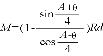
상기(5)식으로부터, 문자 N은 다음과 같이 얻을 수 있다.From the above formula (5), the letter N can be obtained as follows.

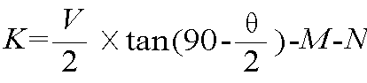
식(4)에 식(6)과 (7)을 대입시킴에 의해 문자 K는 다음과 같이 얻을 수 있다.By substituting equations (6) and (7) into equation (4), the letter K can be obtained as follows.
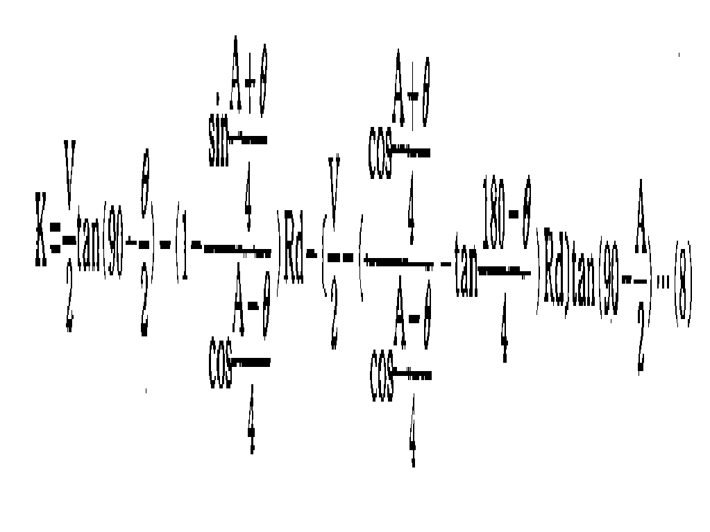
한편, 문자 X는 다음과 같이 나타낼 수 있다.On the other hand, the letter X can be represented as follows.

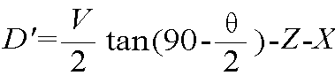
또 문자 D'는 다음과 같이 나타낼 수 있다.The letter D 'can also be represented as
따라서, 식(1) 및 식(9)에 대한 식(2), (3) 및 (8)에 의해, 거리 D'는 다음과 같이 얻을 수 있다.Therefore, by the formulas (2), (3) and (8) for the formulas (1) and (9), the distance D 'can be obtained as follows.

…………………………(10)… … … … … … … … … … 10
그러므로, 거리 D'는 다음과 같은 함수로 나타낼 수 있다.Therefore, the distance D 'can be expressed by the following function.
D'=f(T, A, Rd, Rp,V)……………………………………………………(11)D '= f (T, A, Rd, Rp, V)... … … … … … … … … … … … … … … … … … … … (11)
따라서, 거리D'는 피가공물(W)의 두께(T), 벤딩 각(A), 하부공구(15)의 벤딩홈(15B)내에 형성된 쇼울더에지의 반경(Rp), 상부공구(11)의 하단(11B)에 형성된 반경(Rp)과 벤딩홈(15B)의 폭(V)과 같은 데이타를 설정함에 의해 상기 식에 근거된 제어수단에 따라 결정될 수 있다.Therefore, the distance D 'is the thickness T of the workpiece W, the bending angle A, the radius Rp of the shoulder edge formed in the bending
상기수식(11)은 피가공물(W)의 벤딩 작업에서 발생되는 기본요소를 고려하지 않고 있음으로, 이 기본요소를 보정함이 필요하다. 따라서 다음과 같은 보정이 고려되어야 한다.![]()
![]()
![]()
![]()
![]()
![]()
![]()
![]()
상기보정![]()
![]()
![]()
![]()
![]()
![]()
![]()
![]()
BF=C![]()
![]()
상기 수식(12)에 있어서, C는 상수, B는 벤딩될 피가공물 W의 벤딩길이를 나타낸다. 상기 상수 C는 벤딩홈(15)의 폭 V, 피가공물(W)의 두계(T), 쇼울더에지의 반경(Rd), 쇼울더에지의 마찰계수(μ)와 같은 함수로 표시될 수 있는바 다음과 같다.In Equation (12), C is a constant and B represents a bending length of the workpiece W to be bent. The constant C may be expressed as a function such as the width V of the bending
C=f(V, T, Rd, μ)C = f (V, T, Rd, μ)
피가공물(W)을 90℃로 벤딩할 경우, 하부공구(15)에 놓인 피가공물은, 이 하부공구(15)위에서 피가공물(W)이 상부공구(11)와 계합되고, 피가공물(w)의 벤딩동작이 시작된 후에 벤딩 압력이 점차로 증가하기 시작해서, 피가공물의 벤딩각이 약 130°와 120°사이에서, 그 각도 범위가 좁혀짐에 따라 벤딩압력이 낮아지고, 벤딩 압력은 피가공물의 벤딩 각도가 약 95°및 93°사이의 범위로 될때 다시 증가하며, 벤딩 각도가 90°에 달할때 벤딩 압력이 신속히 증가한 후에 벤딩력이 소정치에 달하면 하부공구(15)위에 놓여 있는 피가공물(W)이 벤딩된다는 것은 잘 알려져 있는 사실이다. 환언하면, 피가공물(W)을 벤딩하는 실제 벤딩력은 벤딩 각 도에 따라 상이하지만 실제 벤딩력(BF')은 벤딩홈(15B)의 폭(V), 피가공물(W)의 두께(T) 및 벤딩각의 함수로서 표시할 수 있는 바 다음과 같다.When the workpiece W is bent at 90 ° C., the workpiece placed on the
BF'=f(V, T, A)×BF……………………………………………………(13)BF '= f (V, T, A) x BF... … … … … … … … … … … … … … … … … … … … (13)
상술과 같이, 실제의 벤딩력(BF')은 상기 수식(13)이나 휨 검지기(31)에 의하여 검지된 램부재(13)의 상향휨에 근거하여 계산에 의해 얻을 수 있다. 수식(13)에 의하여 얻어진 실제 벤딩력(BF')은, 비임부재(9)의 상향휨이 너무 적어 휨 검지기(31)에 의하여 검지될 수 없을 경우에만 사용된다.As described above, the actual bending force BF 'can be obtained by calculation based on the upward deflection of the
이와같이![]()
![]()
![]()
![]()
![]()
![]()
![]()
![]()
![]()
![]()
![]()
![]()
보정![]()
![]()
![]()
![]()
![]()
![]()
보정![]()
![]()
![]()
![]()
보정![]()
![]()
![]()
![]()
![]()
![]()
![]()
![]()
이와같이, 피가공물(W)의 벤딩력에 의하여 생긴 기본요소를 고려하여, 상부공구(11)의 하단(11B)과 원측상정 사이의 거리 D는 다음과 같이 표시될 수 있다.In this way, in consideration of the basic elements created by the bending force of the workpiece W, the distance D between the
D=D'-(![]()
![]()
![]()
![]()
![]()
![]()
![]()
![]()
![]()
![]()
또한, 상기 수식(18)은 다음과 같이도 표시할 수 있다.In addition, the formula (18) can also be expressed as follows.
D=f(V, T, Rd, Rp)-f(BF', B, K, T, V, K2)D = f (V, T, Rd, Rp) -f (BF ', B, K, T, V, K 2 )
자동입력수단(155)상의 수동입력수단의 제어와 상기 데이타에 입각한 연산제어를 제어함에 의하여 피가공물(W)의 벤딩에 필요한 여러 데이타를 제어수단(151)내에 설정함으로써 피가공물(W)은 어떤 각도로도 자동으로 벤딩할 수 있다. 1개의 피가공물은 그 자체가 울퉁불퉁한 자재일지라도 복수개의 서로 다른 각도와 벤딩길이를 갖는 형태로 순차적으로 벤딩될 수 잇으며 여러가지 데이타의 설정에 의하여 자동적으로 벤딩되도록 할 수 있다.By controlling the manual input means on the automatic input means 155 and the arithmetic control based on the data, various pieces of data necessary for the bending of the workpiece W are set in the control means 151 so that the workpiece W It can bend automatically at any angle. One workpiece can be bent sequentially in the form of a plurality of different angles and bending lengths, even if the material itself is uneven, and can be automatically bent by setting various data.
피가공물을 반원통 형상으로 벤딩하는 경우에 있어 제11도, 제12도 및 제13도에 표시된 바와같이, 피가공물(W)은 게이징장치(39)의 스토퍼(55a) 및 (55b)와의 접촉에 의하여 그 후단이 먼저 벤딩된 후에, 각 스트로우크에서 조정된 스트로우크 길이로서 램부재(13)의 각 스트로우크후, 아주 약간의 등거리만큼 전방으로 이동하거나 이송된다. 반지름(R)과 벤딩 각 A로써 반원통 형상으로 피가공물을 벤딩할 경우, 피가공물(W)의 반원통 형상의 전개된 길이(I)는 다음과 같이 반지름(R), 벤딩각도(A) 및 계수(K)의 함수로서 표시될 수 있다.In the case where the workpiece is bent in a semi-cylindrical shape, as shown in FIGS. 11, 12, and 13, the workpiece W is disposed with the
l=f(A, R, K1)l = f (A, R, K 1 )
또한, 벤딩작업의 회수나 램부재의 스트로우크는 다음과 같이 표시될 수 있다.In addition, the number of bending operations or the stroke of the ram member may be expressed as follows.
n=f(A, R)n = f (A, R)
더우기, 피가공물(W)이 램부재(13)의 각 스트로우크후에 이동 또는 이송될 거리 또는 피치(p)는 다음과 같이 표시될 수 있다.Furthermore, the distance or pitch p at which the workpiece W will be moved or conveyed after each stroke of the
p=l/np = l / n
이와같이, 피치(p)는 벤딩 각 A, 반지름 R 및 구부리는 작업회수 n의 데이타 기입항목을 집합함으로써 얻어질 수 있다. 이에 반하여, 벤딩 작업회수(n)는 피치(p), 벤딩 각(A) 및 반지름(R)의 데이타 기입 항목을 설정함으로써 얻을 수 있다. 또한, 피치(p)는 벤딩작업의 확실한 회수, 예컨대 20번과 같은 회수를 제어수단(151)에 기억시키고 벤딩 각(A) 및 반지름(R)만의 데이타를 설정함으로써 얻을 수 있다, 제12(a)도에 있어서, 하부공구(15)에 의하여 파지된 피가공물(W)이 일차 벤딩되는 벤딩깊이(D1)는, 제12(b)에 표시된 바와같이 상부공구(11)의 하단(11B)과 최초 측정점 사이의 거리를 표시하며 하부공구(15)에 의하여 파지되는 피가공물이 2차로 벤딩되는 벤딩깊이(D2)는 다음과 같이 표시될 수 있다.As such, the pitch p can be obtained by aggregating the data entries of the bending angle A, the radius R and the bending number of work n. On the contrary, the bending work frequency n can be obtained by setting data entry items of the pitch p, the bending angle A and the radius R. FIG. Further, the pitch p can be obtained by storing a certain number of bending operations, for example, number 20, in the control means 151 and setting data of only the bending angle A and the radius R. In Fig. a), the bending depth D 1 at which the workpiece W gripped by the
D2=D1-C2 D 2 = D 1 -C 2
제12(b)도에 있어서 가상선은 피가공물(W)이 1차 벤딩된 후 2차 벤딩을 위하여 전방으로 이동하는 것을 나타내며, 실선은 가상선으로 표시된 바와같이 전방으로 이동한 다음 2차 벤딩된 피가공물(W)을 표시한다. 동일하게 m 시간동안 벤딩된 벤딩깊이(Dm)는 제12(d)도에 표시된 바와같이 다음으로 표시될 수 있다.In FIG. 12 (b), the imaginary line indicates that the workpiece W is moved forward for the second bending after the first bend, and the solid line is moved forward and then the second bending as indicated by the imaginary line. The processed workpiece W is displayed. Similarly, the bending depth Dm bent for m time may be represented as follows as shown in FIG. 12 (d).
Dm=D1-CmDm = D 1 -Cm
이와같이, 상부공구(11)의 하단(11B)과 m시점에서의 원측정 점사이의 벤딩깊이(Dm)는, m시점에서의 거리(Dm)를 얻음으로써 결정될 수 있으며, 그 벤딩깊이는 벤딩 때마다 매번 제어될 수 있다.In this way, the bending depth Dm between the
제12(a)도에서 볼때, 치수(b)는 벤딩점과 벤딩홈(15B)의 어깨(shoulder)사이의 거리를 나타내며, 다음과 같이 벤딩홈의 넓이(V1), 벤딩 각(A) 및 성형작업의 회수(n)의 함수로서 표시할 수 있다.In FIG. 12 (a), the dimension (b) represents the distance between the bending point and the shoulder of the bending
b=f(V1, A, n)b = f (V 1 , A, n)
제11도에 있어서 n시점에서의 각각의 각도 αm, βm, γm 및 θm과 치수(bm)는 다음과 같이 표시될 수 있다.In FIG. 11, the angles αm, βm, γm, and θm and the dimension bm at the time n can be expressed as follows.
αm=f(A, m, n)αm = f (A, m, n)
βm=f(A, M, n)βm = f (A, M, n)
γm=f(b, p, bn, V, αm)γm = f (b, p, bn, V, αm)
θm=180-γm=αmθm = 180-γm = αm
다시 제10도에 있어서, 피가공물을 반원통인 각도로 벤딩할 경우, 피가공물(W)이 계합되고 있는 벤딩홈(15B)의 어깨(C) 사이의 거리는 벤딩홈(15B)이 하부공구(15)의 상부표면과 접촉중에 있는 가상점(C) 사이의 거리(V)보다 넓은바, 이는 벤딩홈(15B)의 상부가 횡단면도에서 반지름(Rd)을 갖는 반원이 되도록 형성되어 있기 때문이다. 따라서 실제의 계합 폭(V1)은 다음과 같이 표시될 수 있다.In FIG. 10, when the workpiece is bent at a semicylindrical angle, the distance between the shoulders C of the bending
V=f(V1, Rd, θ)V = f (V 1 , Rd, θ)
그러므로, 거리(Cm)는 다음과 같이 표시될 수 있다.Therefore, the distance Cm can be expressed as follows.
Cm=f(V1, θm)Cm = f (V 1 , θm)
그리고 m 시점에서의 벤딩깊이(Dm)는 다음과 같이 얻을 수 있다.The bending depth Dm at time m can be obtained as follows.
Dm=D1-CmDm = D 1 -Cm
1차 벤딩깊이(D1)는 다음과 같이 얻어질 수 있다.The primary bending depth D 1 can be obtained as follows.
D1=f(A, n, V1, T,![]()
![]()
제13도에 있어서, 피가공물(W)의 벤딩지점과 게이징 장치(39)의 스토퍼(55a) 및 (55b)사이의 계측 거리(H1)는 다음과 같이 H2, H3, H4및 bn+1 의 치수로 표시될 수 있다.In FIG. 13, the measurement distance H 1 between the bending point of the workpiece W and the
H1=H3+bn+1+H4 H 1 = H 3 + bn + 1 + H 4
치수 H4는 다음과 같이 두께(T), 벤딩 각(A) 및 기계적 기본요소(K2)의 함수로서 표시될 수 있다.Dimension H 4 can be expressed as a function of thickness T, bending angle A and mechanical element K 2 as follows.
H2=f(T, A, K2)H 2 = f (T, A, K 2 )
1차 벤딩 지점과 스트퍼(55a) 및 (55b)사이의 계측거리(L2)는 피가공물(W)의 전개된 치수(kTn)와 관계가 있으며 다음과 같이 표시될 수 있다.The measurement distance L 2 between the primary bending point and the
L2=H3+(n+1)}-kTn=H1-bn+1-f(T, A, K2)+p(n-1)-kTnL 2 = H 3 + (n + 1)}-kTn = H 1 -bn + 1-f (T, A, K 2 ) + p (n-1) -kTn
상기와 같이, m 시점에서의 계측거리 (Cm)는 다음과 같이 표시될 수 있다.As described above, the measurement distance Cm at time m may be expressed as follows.
Lm=L-P(m-1)-kTmLm = L-P (m-1) -kTm
이와같이, 벤딩 작업이 시작되기전의 피가공물(W)의 전개된 길이(Dp)는 다음과 같이 얻어질 수 있다.In this way, the developed length Dp of the workpiece W before the bending operation is started can be obtained as follows.
Dp=H1+H2-f(A, R, T)-P(n-1) 1 kTnDp = H 1 + H 2 -f (A, R, T) -P (n-1) 1 kTn
따라서, m 시점에서의 벤딩깊이(Dm)와 계측거리(Lm)는 제어수단(151)에 대한 데이타의 설정과 피가공물 및 상기 수식의 수단에 의한 산술적 제어를 행함으로써 결정될 수 있다. 그러므로 피가공물(W)은,입수된 데이타에 의하여 램부재(13)의 스트로우크 길이와 게이징장치(39)의 계측거리를 제어함으로써 정확하고 용이하게 어떠한 반원통형상으로도 벤딩될 수 있다. 환언하면, 피가공물(W)은 상부공구가 피가공물과 계합되는 위치를 조정함으로써 어떤 반원통형상으로도 벤딩될 수 있다. 여기에는 본 발명의 바람직한 형태가 예시되고 설명되었지만, 본 발명의 원리를 벗어나지 않는 범위내에서 당해 기술분야에 숙달된 자에 의하여 본 장치는 변결될 수 있는것임을 이해하여야 하며, 따라서 본 발명의 범위는 특허청구범위에 의하여 한정되는것만은 아니라 하겠다.Therefore, the bending depth Dm and the measurement distance Lm at the m point of time can be determined by setting data for the control means 151 and performing arithmetic control by means of the workpiece and the above equation. Therefore, the workpiece W can be bent into any semi-cylindrical shape easily and easily by controlling the stroke length of the
Claims (8)
Applications Claiming Priority (3)
| Application Number | Priority Date | Filing Date | Title |
|---|---|---|---|
| JP80-172571 | 1980-12-09 | ||
| JP55172571A JPS57100819A (en) | 1980-12-09 | 1980-12-09 | Bending angle controlling device in press brake |
| JP172571 | 1980-12-09 |
Publications (2)
| Publication Number | Publication Date |
|---|---|
| KR830007160A KR830007160A (en) | 1983-10-14 |
| KR890002733B1 true KR890002733B1 (en) | 1989-07-26 |
Family
ID=15944297
Family Applications (1)
| Application Number | Title | Priority Date | Filing Date |
|---|---|---|---|
| KR1019810004809A KR890002733B1 (en) | 1980-12-09 | 1981-12-09 | Bending press |
Country Status (2)
| Country | Link |
|---|---|
| JP (1) | JPS57100819A (en) |
| KR (1) | KR890002733B1 (en) |
Families Citing this family (10)
| Publication number | Priority date | Publication date | Assignee | Title |
|---|---|---|---|---|
| JPS59212121A (en) * | 1983-05-17 | 1984-12-01 | Amada Co Ltd | Folding method in press brake |
| JPS6024223A (en) * | 1983-07-19 | 1985-02-06 | Amada Co Ltd | Method for controlling bending angle with press brake |
| JPS61169118A (en) * | 1985-01-22 | 1986-07-30 | Amada Co Ltd | Press machine provided with temperature correction means |
| JPS63290623A (en) * | 1987-05-23 | 1988-11-28 | Toyo Koki:Kk | Press brake |
| JPS63295017A (en) * | 1987-05-26 | 1988-12-01 | Toyo Koki:Kk | Press brake |
| JPH0832341B2 (en) * | 1989-08-31 | 1996-03-29 | 株式会社小松製作所 | Control device for press brake |
| JP2008220218A (en) * | 2007-03-09 | 2008-09-25 | Yanmar Co Ltd | Transplanter |
| JP5737657B2 (en) * | 2010-02-04 | 2015-06-17 | 国立大学法人岐阜大学 | Bending method and system using a press brake |
| JP6103741B2 (en) * | 2012-05-11 | 2017-03-29 | 株式会社ホリカワ工業 | Mold and bending method |
| CN115464009B (en) * | 2022-06-20 | 2023-05-30 | 河北腾耀电子设备有限公司 | Bending machine with high-stability clamping function |
-
1980
- 1980-12-09 JP JP55172571A patent/JPS57100819A/en active Granted
-
1981
- 1981-12-09 KR KR1019810004809A patent/KR890002733B1/en active
Also Published As
| Publication number | Publication date |
|---|---|
| JPH0120927B2 (en) | 1989-04-19 |
| JPS57100819A (en) | 1982-06-23 |
| KR830007160A (en) | 1983-10-14 |
Similar Documents
| Publication | Publication Date | Title |
|---|---|---|
| US4486841A (en) | Bending press | |
| US5461893A (en) | Method and apparatus for bending steel rule | |
| KR970005520B1 (en) | Device and method for controlling a manupulator for a plate bending machine | |
| KR890002733B1 (en) | Bending press | |
| US4761979A (en) | Roller bending apparatus equipped with a curvature measuring unit | |
| US4923383A (en) | Apparatus for mold aligning in a compression molding machine | |
| US4085636A (en) | Method and machine for band sawing | |
| US5182936A (en) | Plate bending machine equipped with a plate clamping manipulator and a plate position detecting device | |
| CA1336570C (en) | Plate bending machine equipped with a plate clamping manipulator and a plate position detecting device | |
| JPH01501127A (en) | Adaptive control system for hydraulic press brakes | |
| US4047411A (en) | Numerically controlled pyramid roll forming machine | |
| US6189364B1 (en) | Bending angle correction method and press brake | |
| GB2066719A (en) | Punching and nibbling machines | |
| US3949588A (en) | Straightening press for rod-like workpiece | |
| JPH0353047B2 (en) | ||
| JP3797718B2 (en) | Press brake | |
| JPS63120000A (en) | Nc mechanical press for powder molding | |
| US3644999A (en) | Apparatus for marking one or more lines on a frame section or the like | |
| JP2818275B2 (en) | Bending method | |
| JPH01289525A (en) | Manipulator for bending machine for plate material and bending machine for plate material provided with position detecting device for plate material | |
| KR0178299B1 (en) | Correction device for deflection of bar | |
| CN220077681U (en) | Full-automatic centering positioning machine | |
| JP2941978B2 (en) | Bending machine with back gauge | |
| JP3459460B2 (en) | Bending equipment | |
| EP0205240A2 (en) | Automatic punching machine for punching a laminar workpiece |