KR20220113902A - Photographing device for checking goods - Google Patents
Photographing device for checking goods Download PDFInfo
- Publication number
- KR20220113902A KR20220113902A KR1020220097887A KR20220097887A KR20220113902A KR 20220113902 A KR20220113902 A KR 20220113902A KR 1020220097887 A KR1020220097887 A KR 1020220097887A KR 20220097887 A KR20220097887 A KR 20220097887A KR 20220113902 A KR20220113902 A KR 20220113902A
- Authority
- KR
- South Korea
- Prior art keywords
- inspection
- camera
- light
- test tray
- pair
- Prior art date
Links
- 238000007689 inspection Methods 0.000 claims abstract description 150
- 238000012360 testing method Methods 0.000 claims description 140
- 238000003825 pressing Methods 0.000 claims description 32
- 238000005286 illumination Methods 0.000 claims description 26
- 239000004065 semiconductor Substances 0.000 claims description 23
- 230000001678 irradiating effect Effects 0.000 claims description 17
- 238000000034 method Methods 0.000 claims description 10
- 230000003028 elevating effect Effects 0.000 claims description 6
- 238000003860 storage Methods 0.000 description 56
- 238000012546 transfer Methods 0.000 description 37
- 230000000712 assembly Effects 0.000 description 21
- 238000000429 assembly Methods 0.000 description 21
- 230000007547 defect Effects 0.000 description 21
- 230000008878 coupling Effects 0.000 description 18
- 238000010168 coupling process Methods 0.000 description 18
- 238000005859 coupling reaction Methods 0.000 description 18
- 238000003780 insertion Methods 0.000 description 12
- 230000037431 insertion Effects 0.000 description 12
- 239000013256 coordination polymer Substances 0.000 description 11
- 238000010586 diagram Methods 0.000 description 10
- NJPPVKZQTLUDBO-UHFFFAOYSA-N novaluron Chemical compound C1=C(Cl)C(OC(F)(F)C(OC(F)(F)F)F)=CC=C1NC(=O)NC(=O)C1=C(F)C=CC=C1F NJPPVKZQTLUDBO-UHFFFAOYSA-N 0.000 description 9
- 239000011521 glass Substances 0.000 description 8
- 238000004519 manufacturing process Methods 0.000 description 8
- 239000000463 material Substances 0.000 description 8
- 238000005452 bending Methods 0.000 description 6
- 230000002950 deficient Effects 0.000 description 5
- 238000009434 installation Methods 0.000 description 5
- 230000008859 change Effects 0.000 description 3
- 230000007257 malfunction Effects 0.000 description 3
- 239000004677 Nylon Substances 0.000 description 2
- 239000000853 adhesive Substances 0.000 description 2
- 230000001070 adhesive effect Effects 0.000 description 2
- 239000003086 colorant Substances 0.000 description 2
- 238000002347 injection Methods 0.000 description 2
- 239000007924 injection Substances 0.000 description 2
- 230000002452 interceptive effect Effects 0.000 description 2
- 230000001788 irregular Effects 0.000 description 2
- 229920001778 nylon Polymers 0.000 description 2
- 230000008569 process Effects 0.000 description 2
- 230000004044 response Effects 0.000 description 2
- JOYRKODLDBILNP-UHFFFAOYSA-N Ethyl urethane Chemical compound CCOC(N)=O JOYRKODLDBILNP-UHFFFAOYSA-N 0.000 description 1
- 230000008901 benefit Effects 0.000 description 1
- 230000008602 contraction Effects 0.000 description 1
- 238000013461 design Methods 0.000 description 1
- 230000006866 deterioration Effects 0.000 description 1
- 230000000694 effects Effects 0.000 description 1
- 238000005516 engineering process Methods 0.000 description 1
- 238000007667 floating Methods 0.000 description 1
- 238000003384 imaging method Methods 0.000 description 1
- 239000000203 mixture Substances 0.000 description 1
- 229920001296 polysiloxane Polymers 0.000 description 1
- 230000002265 prevention Effects 0.000 description 1
- 238000012545 processing Methods 0.000 description 1
- 125000006850 spacer group Chemical group 0.000 description 1
- 230000004304 visual acuity Effects 0.000 description 1
- 239000002699 waste material Substances 0.000 description 1
Images


Classifications
-
- G—PHYSICS
- G01—MEASURING; TESTING
- G01N—INVESTIGATING OR ANALYSING MATERIALS BY DETERMINING THEIR CHEMICAL OR PHYSICAL PROPERTIES
- G01N21/00—Investigating or analysing materials by the use of optical means, i.e. using sub-millimetre waves, infrared, visible or ultraviolet light
- G01N21/84—Systems specially adapted for particular applications
- G01N21/88—Investigating the presence of flaws or contamination
- G01N21/8806—Specially adapted optical and illumination features
-
- G—PHYSICS
- G01—MEASURING; TESTING
- G01R—MEASURING ELECTRIC VARIABLES; MEASURING MAGNETIC VARIABLES
- G01R31/00—Arrangements for testing electric properties; Arrangements for locating electric faults; Arrangements for electrical testing characterised by what is being tested not provided for elsewhere
- G01R31/26—Testing of individual semiconductor devices
- G01R31/2601—Apparatus or methods therefor
-
- G—PHYSICS
- G01—MEASURING; TESTING
- G01R—MEASURING ELECTRIC VARIABLES; MEASURING MAGNETIC VARIABLES
- G01R31/00—Arrangements for testing electric properties; Arrangements for locating electric faults; Arrangements for electrical testing characterised by what is being tested not provided for elsewhere
- G01R31/28—Testing of electronic circuits, e.g. by signal tracer
- G01R31/2851—Testing of integrated circuits [IC]
- G01R31/2855—Environmental, reliability or burn-in testing
- G01R31/286—External aspects, e.g. related to chambers, contacting devices or handlers
- G01R31/2863—Contacting devices, e.g. sockets, burn-in boards or mounting fixtures
-
- G—PHYSICS
- G01—MEASURING; TESTING
- G01N—INVESTIGATING OR ANALYSING MATERIALS BY DETERMINING THEIR CHEMICAL OR PHYSICAL PROPERTIES
- G01N21/00—Investigating or analysing materials by the use of optical means, i.e. using sub-millimetre waves, infrared, visible or ultraviolet light
- G01N21/84—Systems specially adapted for particular applications
- G01N21/88—Investigating the presence of flaws or contamination
- G01N21/8806—Specially adapted optical and illumination features
- G01N2021/8812—Diffuse illumination, e.g. "sky"
- G01N2021/8816—Diffuse illumination, e.g. "sky" by using multiple sources, e.g. LEDs
-
- G—PHYSICS
- G01—MEASURING; TESTING
- G01N—INVESTIGATING OR ANALYSING MATERIALS BY DETERMINING THEIR CHEMICAL OR PHYSICAL PROPERTIES
- G01N21/00—Investigating or analysing materials by the use of optical means, i.e. using sub-millimetre waves, infrared, visible or ultraviolet light
- G01N21/84—Systems specially adapted for particular applications
- G01N21/88—Investigating the presence of flaws or contamination
- G01N21/8806—Specially adapted optical and illumination features
- G01N2021/8835—Adjustable illumination, e.g. software adjustable screen
-
- G—PHYSICS
- G01—MEASURING; TESTING
- G01N—INVESTIGATING OR ANALYSING MATERIALS BY DETERMINING THEIR CHEMICAL OR PHYSICAL PROPERTIES
- G01N2201/00—Features of devices classified in G01N21/00
- G01N2201/10—Scanning
- G01N2201/104—Mechano-optical scan, i.e. object and beam moving
Abstract
Description
본 발명은 생산된 물품의 불량 여부를 검사하는 데 사용될 수 있는 촬영기에 관한 것이다.The present invention relates to an imaging device that can be used to inspect whether a product is defective.
반도체소자 테스트용 핸들러(이하 '핸들러'라 함)는 소정의 제조공정을 거쳐 제조된 반도체소자들을 테스터에 전기적으로 연결한 후 테스트 결과에 따라 반도체소자를 분류하는 장비이다.A semiconductor device test handler (hereinafter referred to as a 'handler') is an equipment that electrically connects semiconductor devices manufactured through a predetermined manufacturing process to a tester and classifies semiconductor devices according to test results.
반도체소자의 테스트를 지원하기 위한 핸들러는 대한민국 공개 특허 10-2002-0053406호나 10-2012-0027248호 등과 같은 다양한 특허 문헌을 통해 공개되어 있다.A handler for supporting a test of a semiconductor device is disclosed through various patent documents such as Korean Patent Laid-Open No. 10-2002-0053406 or 10-2012-0027248.
핸들러는 반도체소자들을 테스터에 전기적으로 연결시키고 테스트 결과에 따라 반도체소자들을 분류하기 위해서 필요한 다수의 부속품들을 가진다. 그리고 부속품들 중에서는 테스트될 반도체소자의 규격 변화에 따라 교체되어야 할 부속품들이 존재한다. 예를 들어, 핸들러는 반도체소자들을 적재하는 테스트트레이와 테스트트레이에 적재된 반도체소자들을 테스터 측으로 가압하기 위한 매치플레이트를 가진다. 테스트트레이와 매치플레이트는 반도체소자와 직접 접촉되기 때문에 반도체소자의 규격 변화에 따라 교체되어야 할 부속품들인 것이다.The handler has a plurality of accessories necessary for electrically connecting the semiconductor devices to the tester and classifying the semiconductor devices according to the test result. And among the accessories, there are accessories that need to be replaced according to a change in the standard of the semiconductor device to be tested. For example, the handler has a test tray on which semiconductor elements are loaded and a match plate for pressing the semiconductor elements loaded on the test tray toward the tester. Since the test tray and the match plate are in direct contact with the semiconductor device, they are components that need to be replaced according to the change in the specifications of the semiconductor device.
그런데, 테스트트레이와 매치플레이트의 기능이나 규격에 불량이 존재 또는 발생하게 되면, 핸들러의 작동 불량이나 반도체소자와 테스터 간의 전기적인 접촉 불량이 발생하게 된다. However, when a defect exists or occurs in the functions or specifications of the test tray and the match plate, an operation failure of the handler or a failure in electrical contact between the semiconductor device and the tester occurs.
따라서 핸들러를 생산하거나 반도체소자의 규격 변화에 따라 테스트트레이와 매치플레이트를 교체하고자 하는 경우에는, 반드시 테스트트레이와 매치플레이트에 대한 불량 여부를 먼저 검사하는 것이 필요하다. 물론, 부속품 교체의 경우가 아니더라도 핸들러의 설치 시에도 부속품의 검사가 필요하다. 예를 들면, 부속품 생산자의 경우 고객사 납품 전에 납품할 부속품에 대한 품질검사를 실시하여야 할 것이며, 고객사의 경우는 품질검사가 확인된 제품을 핸들러에 설치를 하거나 고객사 스스로 수령한 제품의 품질검사를 실시한 후 핸들러에 설치해야 할 수도 있는 것이다.Therefore, when manufacturing a handler or replacing a test tray and a match plate according to a change in the specifications of a semiconductor device, it is necessary to first inspect the test tray and the match plate for defects. Of course, it is necessary to inspect the accessories even when the handler is installed, even if not in the case of replacing the accessories. For example, in the case of an accessory producer, quality inspection of the accessories to be delivered should be conducted before delivery to the customer. You may need to install it in your post handler.
또한, 핸들러를 사용하다보면 일정 기간마다 정기적 또는 비정기적 안전 점검을 해야만 하고, 이러한 경우에도 테스트트레이와 매치플레이트의 장기 사용에 따른 불량 발생 여부를 먼저 검사하는 것이 필요하다. 이 때, 검사가 이루어질 항목에는 긁힘, 깨짐, 세부 부품의 상태 불량이나 기능 불량, 적절한 조립 여부, 부속품의 구부러짐 여부, 두께 및 폭, 부속품 내의 세부구조나 구성 및 형상들과 그들의 각도나 높이를 포함한 위치 그리고 개수 등이 있다. 긁힘, 깨짐, 세부부품의 상태 불량은 제품의 상품성 및 신뢰성을 하락시키고, 세부 부품의 기능 불량이나 부적절한 조립, 구부러짐, 두께 및 폭의 불량은 반도체소자와 테스터 간의 전기적인 접촉에 불량을 발생시킬 수 있다. 그리고 구부러짐, 두께 및 폭의 불량은 핸들러의 적절한 동작에 불량을 발생시킨다. In addition, when using the handler, it is necessary to perform regular or irregular safety inspections at regular or irregular intervals. At this time, the items to be inspected include scratches, cracks, poor condition or malfunction of detailed parts, whether proper assembly, whether or not the parts are bent, thickness and width, detailed structures, configurations and shapes within the accessories, and their angles or heights. location and number. Scratches, cracks, and poor condition of detailed parts reduce the product's marketability and reliability, and malfunction of detailed parts, improper assembly, bending, and defects in thickness and width may cause defects in electrical contact between the semiconductor device and the tester. have. Also, defects in bending, thickness, and width cause defects in the proper operation of the handler.
테스트트레이는 대한민국 공개특허 10-2008-0040654호 등에서 참조되는 바와 같이 반도체소자가 적재될 수 있는 다수의 인서트들을 가지고 있다. 인서트의 본체는 사출 성형되기 때문에 사출 불량이나 깨짐과 같이 육안에 의해 확인될 수 있는 불량을 가질 수 있다. 또한, 테스트트레이는 반도체소자를 고정시키기 위해 스프링에 의해 복원되는 래치를 가지고 있으며, 래치의 고정 기능에 불량이 있을 수도 있다. 그리고 생산 시에 테스트트레이의 프레임의 규격(두께나 폭 등)에 불량이 있거나, 테스트트레이가 오랜 시간 동안 반복적으로 사용되면서 구부러질 수도 있다.The test tray has a plurality of inserts in which semiconductor devices can be loaded, as referenced in Korean Patent Laid-Open Publication No. 10-2008-0040654 and the like. Since the body of the insert is injection molded, it may have defects that can be confirmed with the naked eye, such as injection defects or cracks. In addition, the test tray has a latch that is restored by a spring to fix the semiconductor device, and the fixing function of the latch may be defective. In addition, there may be defects in the frame specifications (thickness or width, etc.) of the test tray during production, or the test tray may be bent as it is used repeatedly for a long time.
매치플레이트는 대한민국 공개특허 10-2014-0127389호 등에서 참조되는 바와 같이 푸셔가 스프링에 의해 탄성 지지되는 상태로 설치판에 설치된다. 이러한 매치플레이트는 육안에 의해 확인될 수 있는 불량뿐만 아니라 푸셔를 탄성 지지하는 스프링의 기능(탄성력 정도)에 대한 불량도 가질 수 있다. 마찬가지로, 생산 시에 매치플레이트의 규격(두께나 폭 등)에 불량이 있거나, 매치플레이트가 오랜 시간 동안 반복적으로 사용되면서 구부러질 수도 있다.The match plate is installed on the mounting plate in a state in which the pusher is elastically supported by a spring, as referenced in Korean Patent Application Laid-Open No. 10-2014-0127389 or the like. Such a match plate may have not only a defect that can be confirmed by the naked eye, but also a defect in the function of the spring elastically supporting the pusher (the degree of elasticity). Similarly, there may be defects in the specifications (thickness, width, etc.) of the match plate during production, or the match plate may be bent after being used repeatedly for a long time.
종래에는 테스트트레이에 대한 검사와 매치플레이트에 대한 검사가 육안으로 이루어졌으며, 그 기능에 대한 불량도 수작업에 의해 이루어졌다.Conventionally, the inspection of the test tray and the inspection of the match plate were performed with the naked eye, and defective functions were also made by hand.
그러나 육안에 의할 경우 작업자의 전문성이나 현재 상태(피로도나 시력 상태 등)에 따라 검사 품질이 달라질 수 있다. 따라서 부속품에 대한 일률적인 양호한 검사 작업이 어렵고, 이는 검사의 신뢰성을 떨어뜨리는 원인이 된다. 또한, 기능에 대한 수작업 검사도 검사 품질의 정확성이 담보되지 못하기 때문에 검사의 신뢰성이 더욱 떨어졌다.However, in the case of the naked eye, the quality of the inspection may vary depending on the professionalism of the operator or the current condition (fatigue or visual acuity, etc.). Therefore, it is difficult to perform uniformly good inspection work on accessories, which causes the reliability of inspection to be lowered. In addition, since the accuracy of inspection quality is not guaranteed even for manual inspection of functions, the reliability of inspection is further deteriorated.
특히, 테스트트레이 및 매치플레이트는 모두 판상의 형태여서 그 구부러짐, 두께 및 폭의 불량에 의해 이동 걸림, 양자 간의 정합 불량, 가압 거리 불량 및 반도체소자와 테스터 간의 접속 불량 등을 가져올 수 있기 때문에 그 구부러짐, 두께 및 폭도 중요한 검사 항목이다. 그런데 테스트트레이 및 매치플레이트의 구부러짐, 두께, 폭 및 강도는 육안으로 확인하기가 매우 곤란하다.In particular, since both the test tray and match plate are in the form of a plate, it can cause movement jamming due to bending, poor thickness and width, poor matching between the two, poor pressing distance, and poor connection between the semiconductor device and the tester. , thickness and width are also important inspection items. However, it is very difficult to visually check the bending, thickness, width, and strength of the test tray and match plate.
물론, 테스트트레이의 외관에 대한 검사장비, 테스트트레이에 대한 기능에 대한 검사장비, 매치플레이트의 외관에 대한 검사장비, 매치플레이트의 기능에 대한 검사장비들을 고려해 볼 수는 있다. 그러나 별도의 여러 검사장비들을 구비하는 것은, 추가 비용에 대한 부담과 공간 활용성의 저하 때문에 바람직하지 못하다.Of course, inspection equipment for the appearance of the test tray, inspection equipment for the function of the test tray, inspection equipment for the appearance of the match plate, and inspection equipment for the function of the match plate may be considered. However, it is not preferable to provide several separate inspection equipment because of the burden of additional cost and the deterioration of space utilization.
일반적으로 테스트트레이와 매치플레이트는 상호 정합하는 관계이기 때문에 모두 판상이면서 그 면적도 대략 비슷하다. 따라서 하나의 검사장비로 동일한 절차에 의해 테스트트레이와 매치플레이트를 모두 검사할 수 있도록 하는 검사장비를 제안해 볼 수도 있다. 그런데, 만일 검사장비 내에서 테스트트레이의 이동과 매치플레이트의 이동 흐름 과정이 동일하다면, 상호 간의 중량 및 개수 차이에서 다음과 같은 몇 가지의 문제가 도출된다.In general, since the test tray and match plate have a matching relationship, they are both plate-shaped and have approximately the same area. Therefore, it is possible to propose an inspection equipment that allows one inspection equipment to inspect both the test tray and the match plate by the same procedure. However, if the movement of the test tray and the movement of the match plate are the same in the inspection equipment, the following problems arise from the difference in weight and number between them.
첫째, 테스트트레이는 핸들러 내에서 십 수 장이 순환하게 되고, 매치플레이트는 테스트위치에만 고정 설치되기 때문에 하나의 핸들러에 적용되는 테스트트레이의 개수와 매치플레이트의 개수는 다르다. 따라서 매치플레이트를 테스트트레이의 이동 흐름과 동일하게 가져가는 것은 시간 낭비를 초래할 수 있다.First, the number of test trays and the number of match plates applied to one handler are different because dozens of test trays are circulated in the handler, and the match plates are fixedly installed only in the test position. Therefore, taking the match plate in the same way as the movement flow of the test tray may result in a waste of time.
둘째, 매치플레이트는 테스트트레이보다 상대적으로 매우 무겁다. 따라서 매치플레이트와 테스트트레이의 무게에 영향을 받는 제반 부품들의 강도를 테스트트레이를 기준으로 설계하면 제반 부품들이 매치플레이트의 무게를 견딜 수 없게 된다. 그렇다고 제반 부품들의 강도를 매치플레이트 기준으로 설계하면 검사장비의 생산비용이 큰 폭으로 상승하게 된다.Second, the match plate is relatively heavier than the test tray. Therefore, if the strength of all parts affected by the weight of the match plate and test tray is designed based on the test tray, all parts cannot withstand the weight of the match plate. However, if the strength of all parts is designed based on the match plate, the production cost of the inspection equipment will rise significantly.
셋째, 테스트트레이나 매치플레이트는 핸들러마다 그 규격이나 특징이 다른데, 핸들러를 운영하는 업체 또는 생산하는 업체 그리고 그에 맞는 부속품을 생산하거나 납품하는 업체는 경우에 따라 소량이더라도 여러 종류의 부속품으로 운영하는 경우도 있기에 각각에 맞는 검사장비를 별도로 구비한다는 것은 막대한 비용을 초래하게 된다.Third, test trays and match plates have different specifications and characteristics for each handler. In some cases, the company that operates the handler or the company that produces it and the company that produces or supplies the appropriate accessories operates it with several types of accessories even in small quantities. Therefore, separately providing inspection equipment suitable for each incurs a huge cost.
넷째, 테스트트레이나 매치플레이트는 각각 검사해야할 부분들이 어디냐에 따라 조명의 조사각이 달라져야할 필요가 있어서 어느 한 부분을 기준으로 한 조사각을 가지는 조명으로는 정확한 검사를 진행하기가 곤란할 수 있다.Fourth, the test tray or match plate needs to have a different irradiation angle depending on where the parts to be inspected are, so it may be difficult to perform an accurate inspection with lighting having an irradiation angle based on any one part.
본 발명은 카메라와 조명이 상호 결합되어 있어서 함께 이동할 수 있으면서도 조명의 조사각도를 변경하면서 물품을 촬영할 수 있는 기술을 제공하는 것이다.The present invention is to provide a technology capable of photographing an article while changing the irradiation angle of the light while being able to move together because the camera and the light are mutually coupled.
위와 같은 목적을 달성하기 위한 본 발명에 따른 물품 검사용 촬영기는, 검사해야 할 검사대상물의 일면에 수직한 방향에 위치한 상태에서 상기 검사대상물의 일면에 있는 검사부분을 촬영하는 카메라; 상기 카메라에 결합되어서 상기 카메라와 함께 이동할 수 있으며, 상기 일면에 수직한 조사각도로 빛을 조사하는 수직 조명; 및 상기 카메라에 결합되어서 상기 카메라와 함께 이동할 수 있으며, 상기 일면에 대하여 상기 일면과 0도보다는 크고 90도보다는 작은 각의 범위 내의 조사각도로 빛을 조사하는 적어도 하나 이상의 경사 조명; 을 포함하고, 상기 수직 조명과 상기 적어도 하나 이상의 경사 조명은 제어장치에 의해 독립적으로 제어된다.A photographing apparatus for inspecting an article according to the present invention for achieving the above object includes: a camera for photographing an inspection portion on one surface of the inspection object in a state located in a direction perpendicular to one surface of the inspection object to be inspected; a vertical illumination coupled to the camera and capable of moving together with the camera, irradiating light at an irradiation angle perpendicular to the one surface; and at least one inclined light coupled to the camera and capable of moving together with the camera, irradiating light at an irradiating angle within the range of angles greater than 0 degrees and less than 90 degrees with respect to the one surface; Including, the vertical illumination and the at least one or more inclined illumination are independently controlled by a control device.
상기 경사 조명은 복수개로 구비되되, 복수개의 경사 조명은 상호 다른 각으로 상기 일면에 대하여 빛을 조사한다.A plurality of oblique lights are provided, and the plurality of oblique lights irradiate light to the one surface at different angles.
상기 수직 조명은 다수개의 광원을 가지며, 상기 다수개의 광원 중 적어도 하나는 나머지 광원들과 다른 색의 빛을 조사한다.The vertical illumination includes a plurality of light sources, and at least one of the plurality of light sources irradiates light of a color different from that of the other light sources.
상기 경사 조명은 다수개의 광원을 가지며, 상기 다수개의 광원 중 적어도 하나는 나머지 광원들과 다른 색의 빛을 조사한다.The oblique illumination includes a plurality of light sources, and at least one of the plurality of light sources irradiates light of a color different from that of the other light sources.
상기 다수개의 광원은 조사하는 빛의 세기가 상기 제어장치에 의해 조절될 수 있다.The intensity of the light irradiated to the plurality of light sources may be adjusted by the control device.
상기 경사 조명은 다수개의 광원을 가지며, 상기 다수개의 광원은 상기 일면에 평행한 가상면 상에 원의 형태로 배치된다.The oblique illumination has a plurality of light sources, and the plurality of light sources are arranged in a circle shape on an imaginary surface parallel to the one surface.
본 발명에 따르면 다음과 같은 효과가 있다.According to the present invention, there are the following effects.
첫째, 조명에 있는 광원들의 배치 구조를 변경하지 않고서도 조사각을 변경하면서 촬영할 수 있기 때문에 물품에 대한 흠결 검사의 정확도가 상승한다.First, since it is possible to photograph while changing the irradiation angle without changing the arrangement structure of the light sources in the lighting, the accuracy of the defect inspection on the article is increased.
둘째, 조사되는 빛의 색을 다양하게 조절할 수 있기 때문에 검사의 정확도가 더욱 상승한다.Second, since the color of the irradiated light can be adjusted in various ways, the accuracy of the inspection is further increased.
셋째, 카메라의 촬영각을 확보하면서도 수직 조명과 적어도 하나 이상의 경사 조명들이 카메라에 결합된 상태에서 일체로 이동할 수 있기 때문에 장비의 설계가 용이하다.Third, the design of equipment is easy because the vertical lighting and at least one or more inclined lights can be moved integrally while being coupled to the camera while securing the shooting angle of the camera.
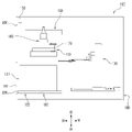
도 1은 본 발명의 일 실시예에 따른 촬영기가 적용된 검사장비에 대한 구조를 보여주는 개념적인 정면도이다.
도 2는 도 1의 검사장비에 대한 구조를 보여주는 개념적인 측면도이다.
도 3은 도 1의 검사장비에 대한 구조를 보여주는 개념적인 평면도이다.
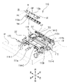
도 4는 도 1의 검사장비에 적용된 지지장치에 대한 사시도이다.
도 5는 도 4의 지지장치에 대한 일부 분해도이다.
도 6은 도 4의 지지장치의 작동을 설명하기 위한 참조도이다.
도 7은 도 4의 지지장치에 적용된 받침기를 설명하기 위한 참조도이다.
도 8은 도 4의 지지장치에 적용된 받침기에 대한 발췌도이다.
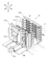
도 9는 도 1의 검사장비에 적용된 수납장치에 대한 사시도이다.
도 10의 도 9의 수납장치에 대한 일부 분해도이다.
도 11은 도 9의 수납장치에 적용된 무빙기의 작동을 설명하기 위한 참조도이다.
도 12는 도 1의 검사장비에 적용된 전후진장치에 대한 발췌 평면도이다.
도 13의 도 12의 전후진장치의 작동을 설명하기 위한 참조도이다.
도 14는 도 1의 검사장비에 적용된 트랜스퍼장치에 대한 사시도이다.
도 15는 도 14의 트랜스퍼장치에 적용된 파지기에 대한 저면 사시도이다.
도 16은 도 14의 트랜스퍼장치에 적용된 파지기를 설명하기 위한 참조도이다.
도 17은 도 14의 트랜스퍼장치의 작동을 설명하기 위한 참조도이다.
도 18은 도 14의 트랜스퍼장치가 파지기의 높이를 조절한 상태를 보여준다.
도 19는 도 14의 트랜스퍼장치가 테스트트레이를 파지할 수 있는 상태를 보여준다.
도 20은 도 14의 트랜스퍼장치가 테스트트레이를 수납장치로부터 인출한 상태를 보여준다.
도 21은 도 14의 트랜스퍼장치가 테스트트레이를 지지장치로 공급할 수 있는 상태를 보여준다.
도 22는 도 14의 트랜스퍼장치가 지지장치로 테스트트레이를 공급하는 상태를 보여준다.
도 23은 도 14의 트랜스퍼장치가 테스트트레이를 180도 회전시킨 상태를 보여준다.
도 24는 도 1의 검사장비에 적용된 검사장치에 대한 발췌도이다.
도 25는 도 24의 검사장치에 적용된 본 발명의 일 실시예에 따른 촬영기에 대한 개략적인 절개도이다.
도 26은 도 25의 촬영기에 대한 개념적인 구조도이다.
도 27은 도 24의 검사장치에 적용된 압력측정기에 대한 개요적인 구조도이다.
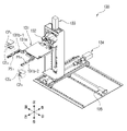
도 28은 도 1의 검사장비에 적용된 이동장치에 대한 사시도이다.
도 29는 도 1의 검사장비에 적용된 받침대에 대한 측단면도이다.
도 30은 도 1의 검사장비에 적용된 개폐도어에 대한 사시도이다.
도 31은 도 30의 개폐도어에 대한 다른 각도에서 바라본 사시도이다.
도 32는 도 30의 개폐도어에 적용된 정렬바의 기능을 설명하기 위한 참조도이다.
도 33은 도 1의 검사장비에 적용된 케이스에 구비되는 고정기에 대한 개략도이다.1 is a conceptual front view showing the structure of an inspection equipment to which a photographing machine according to an embodiment of the present invention is applied.
FIG. 2 is a conceptual side view showing the structure of the inspection equipment of FIG. 1 .
FIG. 3 is a conceptual plan view showing the structure of the inspection equipment of FIG. 1 .
4 is a perspective view of a support device applied to the inspection equipment of FIG. 1 .
FIG. 5 is a partially exploded view of the support device of FIG. 4 .
6 is a reference view for explaining the operation of the support device of FIG.
FIG. 7 is a reference view for explaining a supporter applied to the support device of FIG. 4 .
FIG. 8 is an excerpt of a supporter applied to the support device of FIG. 4 .
9 is a perspective view of a storage device applied to the inspection equipment of FIG.
It is a partial exploded view of the storage device of FIG.
FIG. 11 is a reference view for explaining the operation of the ice moving machine applied to the storage device of FIG. 9 .
12 is an excerpted plan view of the forward/backward device applied to the inspection equipment of FIG. 1 .
It is a reference diagram for explaining the operation of the forward/backward device of FIG. 12 of FIG. 13 .
14 is a perspective view of a transfer device applied to the inspection equipment of FIG. 1 .
15 is a bottom perspective view of a gripper applied to the transfer device of FIG. 14 .
16 is a reference view for explaining a gripper applied to the transfer device of FIG. 14 .
17 is a reference diagram for explaining the operation of the transfer device of FIG. 14 .
18 shows a state in which the transfer device of FIG. 14 adjusts the height of the gripper.
19 shows a state in which the transfer device of FIG. 14 can hold the test tray.
20 shows a state in which the transfer device of FIG. 14 takes out the test tray from the storage device.
21 shows a state in which the transfer device of FIG. 14 can supply the test tray to the support device.
22 shows a state in which the transfer device of FIG. 14 supplies the test tray to the support device.
23 shows a state in which the transfer device of FIG. 14 rotates the
24 is an excerpt of an inspection device applied to the inspection equipment of FIG. 1 .
25 is a schematic cut-away view of a camera according to an embodiment of the present invention applied to the inspection apparatus of FIG.
FIG. 26 is a conceptual structural diagram of the camera of FIG. 25 .
27 is a schematic structural diagram of a pressure gauge applied to the inspection device of FIG. 24 .
28 is a perspective view of a moving device applied to the inspection equipment of FIG. 1 .
29 is a side cross-sectional view of the pedestal applied to the inspection equipment of FIG.
30 is a perspective view of an opening/closing door applied to the inspection equipment of FIG. 1 .
FIG. 31 is a perspective view viewed from another angle with respect to the opening/closing door of FIG. 30 .
FIG. 32 is a reference view for explaining the function of the alignment bar applied to the opening/closing door of FIG. 30 .
33 is a schematic view of a fixture provided in a case applied to the inspection equipment of FIG.
이하 본 발명에 따른 바람직한 실시예에 대하여 설명한다. 참고로 설명의 간결함을 위해 중복되는 설명은 가급적 생략하거나 압축한다.Hereinafter, preferred embodiments according to the present invention will be described. For reference, overlapping descriptions are omitted or compressed as much as possible for the sake of brevity.
한편, 핸들러용 부속품을 검사하는 검사장비(100, 이하 '검사장비'라 약칭함)에 의해 검사되는 검사대상물인 테스트트레이와 매치플레이트는 반도체소자를 테스트할 때 반도체소자를 테스터에 전기적으로 접속시키는 핸들러에 구비되는 부속품이다. 테스트트레이는 다수의 반도체소자를 적재할 수 있는 부속품이고, 매치플레이트는 테스트트레이에 적재된 반도체소자들을 테스터 측으로 가압하기 위한 부속품이다. 따라서 본 설명에서는 테스트트레이와 매치플레이트를 통칭할 때 부속품이라 명칭한다.On the other hand, the test tray and match plate, which are inspection objects that are inspected by inspection equipment (100, hereinafter abbreviated as 'inspection equipment') that inspect accessories for handlers, electrically connect the semiconductor element to the tester when testing the semiconductor element. It is an accessory provided in the handler. The test tray is an accessory for loading a plurality of semiconductor devices, and the match plate is an accessory for pressing the semiconductor devices loaded on the test tray toward the tester. Therefore, in this description, when the test tray and the match plate are collectively referred to as an accessory.
<전체 구성에 대한 개요><Overview of the overall configuration>
도 1 내지 도 3은 검사장비(100, 이하 '검사장비'라 약칭함)에 대한 개념적인 구조도로서, 도 1은 정면도, 도 2는 측면도, 도 3은 평면도이다.1 to 3 are conceptual structural diagrams of an inspection equipment 100 (hereinafter abbreviated as 'inspection equipment'), in which Fig. 1 is a front view, Fig. 2 is a side view, and Fig. 3 is a plan view.
도 1 내지 도 3을 참조하면, 검사장비(100)는 지지장치(110), 수납장치(121), 전후진장치(122), 트랜스퍼장치(130), 검사장치(140), 이동장치(150), 제어장치(160), 받침대(170), 케이스(180) 및 개폐도어(190)를 포함한다. 참고로, 위의 지지장치(110), 수납장치(121), 전후진장치(122) 및 개폐도어(190)는 좌우 한 쌍으로 상호 대칭되게 구비되므로, 좌측의 지지장치(110), 수납장치(121), 전후진장치(122) 및 개폐도어(190)에 대한 설명으로 우측의 지지장치(110), 수납장치(121), 전후진장치(122) 및 개폐도어(190)에 대한 설명을 갈음한다.1 to 3 , the
지지장치(110)는 검사위치(TP)에 있는 부속품을 지지하며, 설치판(IP)에 설치된다.The
수납장치(121)는 지지장치(110)의 하방에 구비되며, 테스트트레이들을 수납할 수 있다.The
전후진장치(122)는 수납장치(121)를 전후 방향으로 전후진시킨다.The forward and
트랜스퍼장치(130)는 수납장치(120)에 있는 테스트트레이를 지지장치(110)로 이동시키거나 지지장치(110)에 의해 지지되고 있는 테스트트레이를 수납장치(120)로 이동시킨다.The
검사장치(140)는 지지장치(110)에 의해 지지된 상태로 검사위치(TP)에 있는 부속품에 대한 검사를 수행하기 위해 마련된다.The
이동장치(150)는 설치판에 설치되며, 검사장치(140)를 수평 방향인 좌우 방향이나 전후 방향으로 이동시킨다.The moving
제어장치(160)는 제어가 필요한 각 구성들을 제어하며, 검사장치(140)에 의해 검사된 결과를 판단한다.The
받침대(170)는 설치판(IP)에 설치되며, 검사장치(140)에 적용될 수 있는 다양한 규격의 누름부재들을 받친다. 이러한 받침대(170)는 다양한 규격의 누름부재의 탈착에 따라 누름부재들의 존재여부를 확인할 수 있는 센서를 구비할 수도 있다.The
케이스(180)는 지지장치(110), 수납장치(121), 전후진장치(122), 트랜스퍼장치(130), 검사장치(140), 이동장치(150) 및 받침대(170)를 내부에 수용한다. 이러한 케이스(180)는 지지장치(110)를 전방으로 노출시키기 위한 제1 노출창(EW1)과 수납장치(121)를 전방으로 노출시키기 위한 제2 노출창(EW2)을 가진다. 따라서 관리자는 자신의 선택과 판단에 따라서 제2 노출창(EW2)을 통해 테스트트레이를 수납장치(121)로 공급하여 트랜스퍼장치(130)에 의해 수납장치(121)에 있는 테스트트레이를 지지장치(110)로 이동시키도록 하거나, 제1 노출창(EW1)을 통해 부속품을 지지장치(110)로 직접 공급할 수도 있다.The
개폐도어(191)는 제2 노출창(EW2)을 개폐시키며, 제2 노출창(EW2)을 폐쇄시키는 동작에 의해 수납장치(121)에 수납된 테스트트레이를 정렬시킨다.The opening/
계속하여 위와 같은 검사장비(100)의 각 구성들에 대하여 더 구체적으로 설명한다. Subsequently, each configuration of the
<지지장치에 대한 설명><Description of the support device>
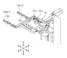
지지장치(110)는 검사위치(TP)에 있는 부속품을 지지한다. 이를 위해 지지장치(110)는 도 4의 발췌도 및 도 5의 일부 분해도에서와 같이 설치판(IP)에 설치되는 한 쌍의 설치대(111a, 111b), 한 쌍의 지지바(112a, 112b), 한 쌍의 롤러조립체(113a, 113b), 승강기(114-1 내지 114-4)들, 간격조정기(115) 및 받침기(116)를 포함한다.The
한 쌍의 설치대(111a, 111b)에는 한 쌍의 지지바(112a, 112b)가 설치된다. 특히 좌측의 제1 설치대(111a)에는 좌측의 제1 롤러조립체(113b) 및 승강기(114-1, 114-2)들도 설치된다. 이러한 한 쌍의 설치대(111a, 111b)는 각각의 후단에 부속품의 후단 위치를 결정하기 위한 스토퍼(ST)를 구비한다. 그리고 한 쌍의 설치대(111a, 111b) 중 좌측에 있는 제1 설치대(111a)는 좌우 방향으로 이동 가능하게 구비되고, 우측에 있는 제2 설치대(111b)는 설치판(IP)에 고정된다. A pair of
한 쌍의 지지바(112a, 112b)는 한 쌍의 설치대(111a, 111b)에 각각 나뉘어 설치되며, 검사위치(TP)에 있는 부속품을 지지한다. 이러한 한 쌍의 지지바(112a, 112b)는 안내돌기(GP)들과 통과구멍(TH)들을 가진다.A pair of support bars (112a, 112b) are installed separately on a pair of installation tables (111a, 111b), respectively, and support the accessories in the inspection position (TP). The pair of
안내돌기(GP)들은 부속품이 적절한 위치에 놓이면서 지지바(112a, 112b)에 얹어지도록 안내한다. 이를 위해 안내돌기(GP)들은 하방으로 갈수록 폭이 넓어지는 형상을 가짐으로써 상측에서 하측 방향으로 놓이는 부속품의 적절한 위치를 안내한다.The guide protrusions GP guide the accessories to be placed on the support bars 112a and 112b while being placed in an appropriate position. To this end, the guide projections (GP) guide the appropriate position of the accessory placed from the upper side to the lower side by having a shape that increases in width toward the lower side.
통과구멍(TH)들은 안내돌기(GP)들 사이에 형성되어 있으며, 후술할 롤러조립체(113a, 113b)의 롤러(R)가 승강할 수 있는 통로를 제공한다.The through holes TH are formed between the guide protrusions GP, and provide a passage through which the roller R of the
한 쌍의 롤러조립체(113a, 113b)는 상방으로 돌출된 다수의 롤러(R)들을 가진다. 여기서 다수의 롤러(R)들은 좌우방향으로의 수평선(HL)을 회전축으로 하여 회전하게 된다. 이러한 한 쌍의 롤러조립체(113a, 113b)는 각각 승강 가능하게 구비된다.The pair of
승강기(114-1 내지 114-4)들은 실린더로 구비되며, 한 쌍의 롤러조립체(113a, 113b)를 승강시킨다. 여기서 좌측 두 개의 승강기(114-1, 114-2)와 제1 롤러조립체(113a)는 결합부재(JE)를 게재하여 결합되어 있고, 우측 두 개의 승강기(114-3, 114-4)와 제2 롤러조립체(113b)는 직접 결합되어 있다. 만일 승강기(114-1 내지 114-4)들에 의해 롤러조립체(113a, 113b)가 상승하면 측면도인 도 6의 (a)에서와 같이 롤러(R)들의 상단이 지지바(112a, 112b)의 상단보다 위로 돌출되고, 승강기(114-1 내지 114-4)에 의해 롤러조립체(113a, 113b)가 하강하면 도 6의 (b)에서와 같이 롤러(R)들의 상단이 지지바(112a, 112b)의 상단과 적어도 동일하거나 그 아래에 위치하도록 내려간다. 따라서 도 6의 (a) 상태에서는 부속품(SP)이 지지바(112a, 112b)와 상하 방향으로 일정 간격(L) 이격된 상태가 되고, 도 6의 (b) 상태에서는 부속품(SP)이 지지바(112a, 112b)에 얹어지게 된다.The elevators (114-1 to 114-4) are provided as cylinders, and lift the pair of roller assemblies (113a, 113b). Here, the left two elevators 114-1 and 114-2 and the
간격조정기(115)는 제1 설치대(111a)를 좌우 방향으로 이동시킨다. 따라서 간격조정기(115)가 작동하면 제1 설치대(111a)에 설치된 제1 지지바(112a)와 제1 롤러조립체(113a)도 좌우 방향으로 이동하게 된다. 이러한 간격조정기(115)에 의해 한 쌍의 지지바(112a, 112b) 간의 간격과 한 쌍의 롤러조립체(113a, 113b) 간의 간격이 조정되기 때문에 다양한 규격의 좌우 폭을 가지는 부속품(SP)들에 대한 검사가 가능해진다.The
한편, 도 7에서와 같이 받침기(116)는 매치플레이트(MP)의 푸셔(PS)가 하방으로 눌려질 때, 매치플레이트(MP)의 프레임(FM)에 있는 지점들 중 하방으로 눌려지는 푸셔(PS)를 사이에 둔 전후 양측 지점(P1, P2)을 받친다. 이를 위해 받침기(116)는 도 8의 발췌도에서 참조되는 바와 같이 이동판(116a), 제1 이동기(116b), 결합판(116c), 전후 한 쌍의 받침판(116d-1, 116d-2), 전후의 승강원(116e-1 내지 116e-4)들 및 제2 이동기(116f)를 포함한다. 더 나아가 본 실시예에서의 받침기(116)는 부속품(SP)의 하방에서 상방을 향해 빛을 비추기 위한 조명기(116g)를 더 포함한다.On the other hand, as in FIG. 7 , when the pusher PS of the match plate MP is pressed downward, the
이동판(116a)에는 결합판(116c), 전후 한 쌍의 받침판(116d-1, 116d-2), 전후의 승강원(116e-1 내지 116e-4)들, 제2 이동기(116f) 및 조명기(116g)가 결합 설치되어 있다. 이러한 이동판(116a)은 제1 이동기(116b)에 의해 좌우 방향으로 이동 가능하게 구비된다.The moving plate 116a includes a coupling plate 116c, a pair of front and
제1 이동기(116b)는 이동판(116a)을 좌우 방향으로 이동시킨다. 따라서 제1 이동기(116b)에 의해 이동판(116a)에 결합된 결합판(116c), 전후 한 쌍의 받침판(116d-1, 116d-2), 전후의 승강원(116e-1 내지 116e-4)들, 제2 이동기(116f) 및 조명기(116g)가 좌우 방향으로 이동될 수 있다.The
결합판(116c)에는 전후 한 쌍의 받침판(116d-1, 116d-2), 전후의 승강원(116e-1 내지 116e-4)들 및 조명기(116g)가 결합 설치된다. 이러한 결합판(116c)은 제2 이동기(116f)에 의해 전후 방향으로 이동 가능하게 구비된다. A pair of front and
조명기(116g)를 사이에 두고 구비되는 전후 한 쌍의 받침판(116d-1, 116d-2)은 도 7에서와 같이 힘(F)로 눌려지는 푸셔(PS)의 양측 지점(P1, P2)에서 매치플레이트(MP)의 프레임(FM)을 받친다. 따라서 푸셔(PF)가 눌려지더라도 매치플레이트(MP)가 휘는 불량이 발생할 염려가 없고, 푸셔(PS)를 탄성 지지하는 스프링(S)에 대한 탄성력도 정확하게 감지될 수 있다.A pair of front and
전후의 승강원(116e-1 내지 116e-4)들은 각각 받침판(116d-1, 116d-2)을 승강시킨다. 즉, 받침판(116d-1, 116d-2)이 매치플레이트(MP)의 프레임(FM)을 지지할 필요가 있는 경우에는, 승강원(116e-1 내지 116e-4)들이 작동하여 받침판(116d-1, 116d-2)을 상승킴으로써 도 7에서와 같이 받침판(116d-1, 116d-2)이 매치플레이트(MP)의 프레임(FM)을 받칠 수 있도록 한다. 참고로, 매치플레이트(MP)의 가장 끝단 쪽의 검사를 할 경우에는 일 측만 지지하여도 무방한 경우도 있고 푸셔(PS)를 탄성 지지하는 스프링(S)도 하나만 구비되는 경우도 있으므로, 경우에 따라서 전후의 승강원(116e-1 내지 116e-4)들 중 전방 측 또는 후방 측 중 어느 일 측의 승강원(116e-1과 116e-2 또는 116e-3과 116e-4)만 구비되거나 전후의 승강원(116e-1 내지 116e-4)들 중 어느 일 측만 작동되도록 제어될 수도 있다.The front and rear elevating
제2 이동기(116f)는 결합판(116c)을 전후 방향으로 이동시킴으로써 전후 한 쌍의 받침판(116d-1, 116d-2), 전후의 승강원(116e-1 내지 116e-4)들 및 조명기(116g)를 전후 방향으로 이동시킨다. 즉, 제1 이동기(116b)와 제2 이동기(116f)의 작동에 따라서 결합판(116c)이 전후 및 좌우 방향으로 이동될 수 있기 때문에 부속품(SP)의 전체 영역에 걸쳐 전후 한 쌍의 받침판(116d-1, 116d-2)과 조명기(116g)가 위치될 수 있다. 물론, 결합판(116c)은 검사 작업의 수행 시에 검사장치(140)의 수직 하방에 위치되도록 검사장치(140)의 이동과 연동하여 이동하게 된다. The second mover 116f is a pair of front and
조명기(116g)는 검사장치(140)에 구비되는 조명에 의한 검사가 불완전할 수 있는 경우에 사용되며, 부속품(SP)의 하측에서 상방으로 빛을 비추도록 하기 위해 마련된다. 이러한 조명기(116g)는 백라이트유닛으로 구비될 수 있으며, 결합판(116c)과 함께 전후 및 좌우 방향으로 이동한다.The
참고로, 받침판(116d-1, 116d-2)과 조명기(116g)가 결합된 상태로 제1 이동기(116b)와 제2 이동기(116f)에 의해서 전후 방향 및 좌우 방향으로 이동하기 때문에 받침판(116d-1, 116d-2)과 조명기(116g)가 검사장치(140)와 대응되는 하방에 위치할 수 있다. 따라서 부속품(SP)의 전체 평면적에 해당하는 받침판(116d-1, 116d-2)과 조명기(116g)를 필요로 하지 않고도, 효율적으로 검사부위에 맞게 검사장치(140)와 대응되게 연동 구동되는 구조를 가진다. 그리고 이러한 구조에 의해 공간 활용과 효율성 증대라는 이점을 얻을 수 있다.For reference, since the
이어서 위의 지지장치(110)의 작동에 대해서 설명한다.Next, the operation of the
간격조정기(115)는 기 입력된 부속품(SP)에 대한 표준 규격 정보에 따라 제1 설치대(111)를 좌우 방향으로 이동시켜서 한 쌍의 지지바(112a, 112b) 간의 좌우 간격과 한 쌍의 롤러조립체(113a, 113b) 간의 좌우 간격을 조정한다. 그리고 승강기(114-1 내지 114-4)들이 작동하여 도 6의 (a)에서와 같이 한 쌍의 롤러조립체(113a, 113b)를 상승시킨다. 한 쌍의 롤러조립체(113a, 113b)가 상승한 상태에서 부속품(SP)은 관리자의 선택에 따라서 수납장치(121)를 경유한 후 트랜스퍼장치(130)에 의해 지지장치(110)로 공급될 수도 있고, 관리자에 의해 직접 제1 노출창(EW1)을 통해 지지장치(110)로 공급될 수도 있다. 이 때, 지지장치(110)로 부속품(SP)이 공급되는 과정에서 먼저 롤러조립체(113a, 113b)의 롤러(R)들에 부속품(SP)이 얹어지게 되기 때문에 트랜스퍼장치(130)나 관리자의 손이 지지바(112a, 112b)와 간섭되는 것이 방지된다. 또한, 제1 노출창(EW1)을 통해 부속품(SP)이 관리자에 의해 직접 지지장치(110)로 공급되는 경우에는, 한 쌍의 롤러조립체(113a, 113b)에 구비된 롤러(R)들에 의해 부속품(SP)의 후방 이동 시에 발생할 있는 이동 마찰이 최소화된다.The
그리고, 부속품(SP)의 후단이 스토퍼(ST)에 접촉함으로써 감지기(도시되지 않음)가 부속품(SP)이 적절한 위치에 있음을 확인하게 되면, 승강기(114-1 내지 114-4)들이 한 쌍의 롤러조립체(113a, 113b)를 하강시킴으로써 도 6의 (b)에서와 같이 부속품(SP)의 양단이 한 쌍의 지지바(112a, 112b)에 얹어지게 된다. 물론, 부속품(SP)이 지지장치(110)에서 수거되는 경우에도 한 쌍의 롤러조립체(13a, 113b)가 승강함으로써 부속품(SP)의 수거 작업을 돕게 된다.And, when the sensor (not shown) confirms that the accessory SP is in an appropriate position by the rear end of the accessory SP in contact with the stopper ST, the elevators 114-1 to 114-4 are a pair By lowering the
한편, 검사장치(140)에 의해 검사위치(TP)에 있는 부속품(SP)에 대한 검사가 이루어질 때, 받침기(116)는 결합판(116c)을 이동시키면서 조명기(116g)를 작동시켜 상방으로 빛을 비추거나, 승강원(116e-1 내지 116e-4)이 작동되어 받침판(116d-1, 116d-2)으로 메치플레이트(MP)의 프레임(FM)을 받친다.On the other hand, when the inspection of the accessory SP at the inspection position TP by the
<수납장치에 대한 설명><Description of storage device>
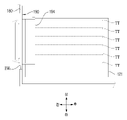
수납장치(121)는 상하 방향으로 여러 개의 테스트트레이를 적재 수납하기 위해 마련된다. 이를 위해 수납장치는 도 9의 발췌도에서와 같이 상호 마주보는 한 쌍의 지지체(121a, 121b), 측방이동기(121c) 및 무빙기(121d)를 가진다.The
한 쌍의 지지체(121a, 121b) 각각은 상하 방향으로 일정 간격 이격된 다수의 적층판(121a-1, 121b-1)들을 가진다. 여기서 적층판(121a-1, 121b-1)들은 테스트트레이(TT)의 양단을 공간에 띄우기 위한 돌출부분(PP)이 구비된다.Each of the pair of
테스트트레이(TT)는 상호 마주보는 적층판(121a-1, 121b-1)의 돌출부분(PP) 위에 좌우 양측이 얹어지는 상태로 수납장치(121)에 수납된다.The test tray TT is accommodated in the
그리고, 한 쌍의 지지체(121a, 121b) 중 좌측의 제1 지지체(121a)는 좌우 방향으로 이동 가능하게 베이스판(BP)에 결합되어 있다.And, the
측방이동기(121c)는 베이스판(BP)에 설치되며, 제1 지지체(121a)를 좌우 방향으로 이동시킴으로써 한 쌍의 지지체(121a, 121b) 간의 좌우 방향으로의 간격을 좁히거나 벌린다. 따라서 다양한 규격의 좌우 폭을 가지는 테스트트레이(TT)들이 수납장치(121)에 적절히 수납될 수 있다.The
한편, 무빙기(121d)는 관리자에 의해 수납장치(121)에 수납된 테스트트레이(TT)를 트랜스퍼장치(130)가 파지할 수 있는 후방으로 이동시키거나, 트랜스퍼장치(130)에 의해 수납장치(121)로 되돌아 온 테스트트레이(TT)를 전방으로 이동시킨다. 이를 위해 무빙기(131d)는 제1 지지체(121a)에 결합 설치되며, 도 10의 일부 분해도에서와 같이 다수의 제1 밀대(121a-1), 제1 이동판(121a-2), 제1 왕복기(121a-3), 다수의 제2 밀대(121a-4), 제2 이동판(121a-5), 제2 왕복기(121a-6), 결합프레임(121a-7) 및 전후진기(121a-8)를 포함한다.On the other hand, the moving
다수의 제1 밀대(121a-1)는 관리자에 의해 수납장치(121)로 수납된 테스트트레이(TT)를 수납장치(121) 내에서 트랜스퍼장치(130)가 파지할 수 있는 후방으로 밀어 이동시키기 위해 사용된다. The plurality of
제1 이동판(121a-2)에는 다수의 제1 밀대(121a-1)가 상하 방향으로 등간격을 가지며 결합되어 있다. 이러한 제1 이동판(121a-2)은 결합프레임(121a-7)에 좌우 방향으로 이동 가능하게 결합된다.A plurality of
제1 왕복기(121a-3)는 제1 이동판(121a-2)을 좌우 방향으로 왕복 이동시킬 수 있다. 따라서 제1 왕복기(121a-3)의 작동에 따라서 개략적인 평면도인 도 11의 (a)에서 참조되는 바와 같이 제1 이동판(121a-2)이 우측으로 이동된 상태에서는 테스트트레이(TT)를 후방으로 밀 수 있는 상태가 되고, 제1 이동판(121a-2)이 좌측으로 이동된 상태에서는 도 11의 (b)에서 참조되는 바와 같이 테스트트레이(TT)와 간섭 없이 전후 방향으로 이동될 수 있다.The
다수의 제2 밀대(121a-4)는 트랜스퍼장치(130)에 의해 수납장치(121)로 되돌아 온 테스트트레이(TT)를 관리자가 편리하게 수거할 수 있도록 전방으로 이동시키기 위해 사용된다. 참고로 도 10에서 다수의 제2 밀대(121a-4) 중 가장 상측의 것을 제외하고 나머지 하방의 것들은 결합프레임(121a-7)에 의해 가려져 있다. The plurality of second push bars 121a - 4 are used to move the test tray TT returned to the
제2 이동판(121a-5)에는 다수의 제2 밀대(121a-4)가 상하 방향으로 등간격을 가지며 결합되어 있다. 이러한 제2 이동판(121a-5)은 제1 이동판(121a-2)의 후방에 일정 간격 이격되게 구비되며, 결합프레임(121a-7)에 좌우 방향으로 이동 가능하게 결합된다.A plurality of
제2 왕복기(121a-6)는 제2 이동판(121a-5)을 좌우 방향으로 왕복 이동시킬 수 있다. 마찬가지로 제2 왕복기(121a-6)에 의해 제2 이동판(121a-5)이 우측으로 이동된 상태에서는 테스트트레이(TT)를 전방으로 밀 수 있는 상태가 되고, 제2 이동판(121a-5)이 좌측으로 이동된 상태에서는 테스트트레이(TT)와 간섭 없이 전후 방향으로 이동될 수 있다.The
결합프레임(121a-7)은 전후 방향으로 이동 가능하게 구비된다. 이러한 결합프레임에는 궁극적으로 다수의 제1 밀대(121a-1), 제1 이동판(121a-2), 제1 왕복기(121a-3), 다수의 제2 밀대(121a-4), 제2 이동판(121a-5) 및 제2 왕복기(121a-6)가 결합되어 있다. 따라서 결합프레임(121a-7)이 전후 방향으로 이동하면, 다수의 제1 밀대(121a-1), 제1 이동판(121a-2), 제1 왕복기(121a-3), 다수의 제2 밀대(121a-4), 제2 이동판(121a-5) 및 제2 왕복기(121a-6)도 전후 방향으로 이동하게 된다.The coupling frame (121a-7) is provided to be movable in the front-rear direction. Ultimately, such a coupling frame includes a plurality of first pushers (121a-1), a first moving plate (121a-2), a first reciprocator (121a-3), a plurality of second pushers (121a-4), and a second The moving
전후진기(121a-8)는 결합프레임(121a-7)을 전후 방향으로 이동시킨다. 물론, 이러한 전후진기(121a-8)의 작동에 의해 우측으로 전진한 제1 밀대(121a-1)가 테스트트레이(TT)를 후방으로 밀어 이동시키거나 제2 밀대(121a-4)가 테스트트레이(TT)를 전방으로 밀어 이동시킨다.The forward/backward mover (121a-8) moves the coupling frame (121a-7) in the front-rear direction. Of course, the
<전후진장치에 대한 설명><Description of the forward/reverse device>
전후진장치(122)는 도 12의 발췌 평면도에서와 같이 베이스판(BP)을 전후 방향으로 전후진시킴으로써 베이스판(BP)에 결합되어 있는 수납장치(121)를 전후 방향으로 전후진시킨다. 도 13에서와 같이 전후진장치(122)에 의해 수납장치(121)가 제2 노출창(EW2) 측으로 최대한 인접하게 전방으로 이동하게 되면 관리자가 테스트트레이(TT)를 수납장치(121)에 수납시키거나 수납장치(121)로부터 테스트트레이(TT)를 수거하는 작업을 편리하게 수행할 수 있다.The forward/
<트랜스퍼장치에 대한 설명><Description of the transfer device>
도 14의 발췌도에서와 같이 트랜스퍼장치(130)는 파지기(131), 회전기(132), 승강기(133), 전후이동기(134) 및 좌우이동기(135)를 포함한다.14 , the
파지기(131)는 테스트트레이(TT)를 파지하거나 파지를 해제한다. 이를 위해 파지기(131)는 도 15에서와 같이 회전판(131a), 한 쌍의 파지레버(131b-1, 131b-2), 구동원(131c), 제1 접촉부재(CP1)들 및 제2 접촉부재(CP2)들을 포함한다.The
회전판(131a)에는 한 쌍의 파지레버(131b-1, 131b-2)와 구동원(131c)이 설치된다. 이러한 회전판(131a)은 회전기(132)에 의해 180도 정역회전 가능하게 설치된다.A pair of grip levers 131b-1 and 131b-2 and a driving
한 쌍의 파지레버(131b-1, 131b-2)는 각각 파지홈(GS1, GS2)들과 방지홈(PS1, PS2)들을 가진다.The pair of
파지홈(GS1, GS2)들은 테스트트레이(TT)를 파지하기 위해 형성되며, 이를 위해 제1 파지레버(131b-1)의 파지홈(GS1)과 제2 파지레버(131b-2)의 파지홈(GS2)은 상호 마주보는 방향으로 개방되어 있다.The gripping grooves GS 1 , GS 2 are formed to grip the test tray TT, and for this purpose, the gripping groove GS 1 of the first
방지홈(PS1, PS2)들은 좌우 방향으로 패인 형태이며, 도 16에서와 한 쌍의 파지레버(131b-1, 131b-2)가 테스트트레이(TT)를 지지장치(110)로 공급하거나 지지장치(110)로부터 테스트트레이(TT)를 회수할 때 한 쌍의 파지레버(131b-1, 131b-2)가 지지장치(110)의 안내돌기(GP)들과 간섭하는 것을 방지한다.The prevention grooves (PS 1 , PS 2 ) are in the form of dents in the left and right directions, and a pair of
구동원(131c)은 한 쌍의 파지레버(131b-1, 131b-2) 중 제2 파지레버(131b-2)를 좌우 방향으로 이동시킴으로써 한 쌍의 파지레버(131b-1, 131b-2) 상호 간의 간격을 조정한다. 이러한 구동원(131c)의 작동에 의해 한 쌍의 파지레버(131b-1, 131b-2)가 테스트트레이(TT)를 파지하거나 파지를 해제할 수 있으며, 한 쌍의 파지레버(131b-1, 131b-2) 간의 간격도 조절될 수 있다. 본 실시예에서처럼 제2 파지레버(131b-2)만 이동되도록 한 경우에는 파지기(131)가 테스트트레이(TT)를 파지하거나 파지를 해제할 때 후술할 좌우이동기(135)의 작동이 다소 필요할 수 있다. 물론, 실시하기에 따라서는 양 파지레버(131b-1, 131b-2)가 모두 이동될 수 있도록 구현될 수도 있다.The driving
제1 접촉부재(CP1)들은 고정된 제1 파지레버(131b-1)의 파지홈(GS1)에 삽입된 상태로 구비된다. 이러한 제1 접촉부재(CP1)들은 탄성적인 수축 팽창이 가능한 재질이면서 다소간 점착성이 있는 실리콘이나 우레탄 등 연질의 고무와 같은 재질로 구비된다. 이러한 제1 접촉부재(CP1)는 제1 파지레버(131b-1)에 유동 되지 못하도록 고정 구비될 수도 있다.The first contact members CP 1 are provided in a state of being inserted into the gripping groove GS 1 of the fixed first gripping
제2 접촉부재(CP2)들은 좌우 이동이 가능한 제2 파지레버(131b-2)의 파지홈(GS2)에 삽입된 상태로 구비된다. 이러한 제2 접촉부재(CP2)는 탄성적인 수축 팽창이 없는 딱딱한 재질이면서 점착성이 없는 재질로 구비된다. 예를 들어, 제2 접촉부재(CP2)들은 M/C나일론(M/C NYLON) 등 경질의 재질로 구비될 수 있다.The second contact members CP 2 are provided in a state of being inserted into the gripping groove GS 2 of the second
위와 같이 제1 접촉부재(CP1)의 재질과 제2 접촉부재(CP2)의 재질을 달리하는 이유는, 회전판(131a)에 이동 불가능하게 고정된 제1 파지레버(131b-1)를 기준으로 테스트트레이(TT)가 정렬된 상태를 유지할 수 있도록 하기 위함이다. 즉, 제1 파지레버(131b-1)로부터 멀어지는 방향으로 제2 파지레버(131b-2)가 이동하여 파지된 테스트트레이(TT)의 파지를 해제할 때 테스트트레이(TT)는 제1 접촉부재(CP1)에 점착된 상태에 있으므로 테스트트레이(TT)가 제2 접촉부재(CP2)의 이동에 호응하여 함께 이동되는 것이 방지된다. 따라서 테스트트레이(TT)가 회전판(131a)에 고정된 제1 파지레버(1312b-1)를 기준으로 적절히 정렬된 상태를 유지하게 된다.As described above, the reason for differentiating the material of the first contact member (CP 1 ) and the material of the second contact member (CP 2 ) is based on the first gripping lever (131b-1) fixed immovably to the rotating plate (131a). This is to keep the test tray TT aligned. That is, when the second
또한, 제2 접촉부재(CP2)는 제2 파지레버(131b-2) 상에서 테스트트레이(TT) 측 방향으로 다소간 유동될 수 있도록 구비될 수 있다. 이러한 경우 스프링과 같은 탄성부재(도시 되지 않음)의 일단은 제2 파지레버(131b-2)에 지지되고 타단은 2 접촉부재(CP2)에 연결되는 구조를 고려해 볼 수 있다. 이러한 예를 가지면, 양 파지레버(131b-1, 131b-2)로 부속품(SP)을 파지하는 경우 적은 힘으로도 파지력의 증대를 가져오고, 제작 공차에 따라 다소 차이 나는 부속품(SP)의 규격에 적절히 대응함으로써 파지 불량이나 강한 파지력에 의한 부속품(SP)의 파손을 방지할 수 있다.In addition, the second contact member CP 2 may be provided to be able to flow more or less in the direction toward the test tray TT on the second
참고로, 양 파지레버(131b-1, 131b-2) 측에 모두 탄성부재(스프링)가 있을 경우에는 탄성부재(스프링)의 탄성력 차로 인한 쏠림의 문제가 발생할 수 있다. 따라서 이러한 문제가 발생하지 않도록 제2 파지레버(131b-2)에만 탄성부재(스프링)을 구현하였다. 그리고 이렇게 함으로써 탄성부재(스프링)가 없는 제1 파지레버(131b-1) 측이 기준면이 되어 파지 및 파지 해지 시 부속품(SP)의 정확한 접촉과 정확한 위치에 정렬된 상태로 안착이 가능해진다, 즉, 딱딱한 재질이면서 점착성이 없는 재질로서 제2 접촉부재(CP2)를 구현한 이유도 부속품(SP)의 파지 및 파지 해제 시에 부속품(SP)의 적절한 정렬을 고려하였기 때문이다. For reference, when there are elastic members (springs) on both sides of the grip levers 131b-1 and 131b-2, there may be a problem of tilting due to a difference in the elastic force of the elastic members (springs). Therefore, an elastic member (spring) is implemented only on the second
회전기(132)는 회전판(131a)을 180도 정역 회전시킴으로써 한 쌍의 파지레버(131b-1, 131b-2)를 180도 정역 회전시키기 위해 마련된다. 이러한 회전기(132)를 구비하는 이유는 테스트트레이(TT)나 매치플레이트(MP)의 상면 측과 하면 측을 모두 검사할 필요가 있기 때문이다. 따라서 테스트트레이(TT)나 매치플레이트(MP)의 테두리를 검사할 필요도 있는 경우에는 회전판(131a)을 -90도, 90도 및 180도만큼 정역 회전시킬 수 있도록 회전기(132)를 구비하는 것도 고려할 수 있다.또한 파지기(131)가 회전을 함에 따라 무게에 따른 처짐 정도가 다르기 때문에 기준높이가 동일한 면이 있는 것이 바람직하므로, 파지기(131)의 양 접촉부재(CP21, CP2)는 서로 다른 재질이면서도 구성도 다른 것이다.The
승강기(133)는 회전기(132)를 승강시킴으로써 회전기(132)에 결합된 파지기(131)를 승강시킨다. The
전후이동기(134)는 승강기(133)를 전후 방향으로 이동시킴으로써 궁극적으로 승강기(133)에 결합된 회전기(132) 및 파지기(131)를 전후 방향으로 이동시킨다. 물론, 전후이동기(134)의 작동에 따른 파지기(131)의 전후 이동에 의해 한 쌍의 파지레버(131b-1, 131b-2)가 수납장치(121)나 지지장치(110)에 있는 테스트트레이(TT)를 파지 할 수 있는 위치로 전진하거나 수납장치(121)나 지지장치(110)로 테스트트레이(TT)를 공급할 수 있는 위치로 전진하게 된다. 물론, 전후이동기(134)는 한 쌍의 파지레버(131b-1, 131b-2)가 테스트트레이(TT)를 파지하거나 파지를 해제한 후에는 파지기(131)를 후진시킨다.The forward/
좌우이동기(135)는 전후이동기(134)를 좌우 방향으로 이동시킴으로써 궁극적으로 전후이동기(134)에 결합된 파지기(131), 회전기(132) 및 승강기(133)를 좌우 방향으로 이동시킨다. 따라서, 트랜스퍼장치(130)는 쌍으로 구비되는 좌우 양측의 수납장치(121)와 좌우 양측의 지지장치(110)에 있는 테스트트레이(TT)를 대상으로 모두 이동 작업을 수행할 수 있다. The left and
이어서 트랜스퍼장치(130)의 작동에 대하여 도 17 내지 도 24의 개략도를 참조하여 설명한다.Next, the operation of the
먼저 도 17의 상태에서 승강기(133)가 작동하여 도 18에서와 같이 파지기(131)를 수납장치(121)에 적재된 이동이 필요한 테스트트레이(TT)를 파지할 수 있는 높이로 위치시킨다.First, in the state of FIG. 17 , the
도 18의 상태에서 전후이동기(134)가 작동하여 파지기(131)를 전진시키면, 도 19에서와 같이 한 쌍의 파지레버(131b-1, 131b-2)가 테스트트레이(TT)를 파지할 수 있는 상태가 된다. 물론, 파지기(131)의 양 파지레버(131b-1, 131b-2) 간의 간격은 벌려져 있다.In the state of FIG. 18, when the forward/
도 19의 상태에서 구동원(131c)이 작동하여 테스트트레이(TT)를 파지한 후, 도 20에서와 같이 전후이동기(134)가 작동하여 파지기(131)를 후진시킨다.In the state of FIG. 19 , after the driving
도 20의 상태가 되면, 승강기(133)가 작동하여 파지기(131)를 상승시킴으로써 도 21에서와 같이 파지기(131)가 지지장치(110)로 테스트트레이(TT)를 공급할 수 있는 높이가 된다.When the state of FIG. 20 is reached, the
도 21의 상태에서 전후이동기(134)가 작동하여 파지기(131)를 전진시켜 도 22의 상태가 되게 한 후, 승강기(133)가 파지기(131)를 약간 하강시킴으로써 테스트트레이(TT)가 롤러조립체(113a, 113b)의 롤러(R)들에 얹어지도록 한다. 그리고 파지기(131)가 테스트트레이(TT)의 파지를 해제하고, 승강기(133)가 파지기(131)를 약간 상승시킨 후 전후이동기(134)가 작동하여 파지기(131)를 후진시킨다. 물론, 테스트트레이(TT)가 롤러(R)들에 얹어지면, 앞서 언급한 바와 같이 롤러조립체(113a, 113b)가 하강함으로써 테스트트레이(TT)가 지지바(112a, 112b)에 얹어지게 된다. 이 때, 트랜스퍼장치(130)에 의해 테스트트레이(TT)가 지지장치(110)의 적절한 위치에 놓이도록 구현할 수도 있지만, 트랜스퍼장치(130)에 의해 지지장치(110)에 놓인 테스트트레이(TT)의 후단이 스토퍼(ST)에 접촉하도록 정렬시키는 별도의 정렬기가 더 구비될 수도 있다. 참고로, 제어적인 측면에서 전후이동기(134)가 파지기(131)를 전진시켜 테스트트레이(TT)를 지지장치(110)의 상측에 위치시킨 다음 롤러조립체(113a, 113b)를 상승시킴으로써 테스트트레이(TT)가 롤러조립체(113a, 113b)의 롤러(R)들에 얹어지도록 한 후, 롤러조립체(113a, 113b)를 하강시킴으로써 테스트트레이(TT)가 지지바(112a, 112b)에 얹어지도록 할 수도 있다. In the state of FIG. 21, the forward/
한편, 테스트트레이(TT)의 상면에 대한 검사가 완료되면, 전후이동기(134) 및 파지기(131)가 작동하여 지지장치(110)로부터 테스트트레이(TT)를 수거한 다음, 도 23에서와 같이 회전기(132)가 작동하여 테스트트레이(TT)를 180도 회전시킨다. 그리고 트랜스퍼장치(130)는 180도 회전된 테스트트레이(TT)를 지지장치(110)로 재공급한다. 이에 따라 검사장치(140)는 180도 회전에 의해 하면이 상방을 향하는 상태로 놓인 테스트트레이(TT)의 하면을 검사하게 된다.On the other hand, when the inspection of the upper surface of the test tray TT is completed, the forward/
차후, 상면 및 하면에 대한 검사가 모두 완료된 테스트트레이(TT)는 트랜스퍼장치(130)에 의해 지지장치(110)로부터 회수된 후, 180도 회전하여 원래의 상태로 복귀된 다음 수납장치(121)로 이동한다. 그리고 트랜스퍼장치(130)는 다음 검사대상인 테스트트레이(TT)를 수납장치(121)로부터 지지장치(110)로 이동시킨다.Afterwards, the test tray TT on which both the upper and lower surfaces are inspected is recovered from the
<검사장치에 대한 설명><Description of inspection device>
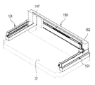
검사장치(140)는 부속품의 외관, 기능 및 규격을 검사하기 위해 마련된다. 이를 위해 검사장치(140)는 도 24의 발췌도에서와 같이 촬영기(141), 제1 승강기(142), 한 쌍의 거리측정기(143), 한 쌍의 압력측정기(144), 한 쌍의 승강프레임(145), 한 쌍의 제2 승강기(146) 및 이동판(147)을 포함한다.The
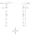
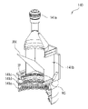
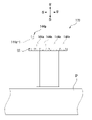
촬영기(141)는 검사해야 할 검사대상 물품인 부속품(SP)의 일면에 있는 검사부분을 촬영하기 위해 마련된다. 이를 위해 촬영기(141)는 이동판(147)에 승강 가능하게 결합되어 있으며, 도 25의 개략적인 절개도 및 도 26의 개념적인 구조도에서와 같이 카메라(141a), 제1 조명(1241b), 제2 조명(141c), 제3 조명(141d) 및 제4 조명(141e)을 포함한다.The photographing
카메라(141a)는 부속품의 상면에 수직한 상방에 위치한 상태에서 수직 하방에 있는 부속품(SP)에 대한 평면을 촬영하기 위해 마련된다.The
제1 조명(141b)은 부속품(SP)의 평면에 수직한 조사각도로 빛을 조사하기 위한 수직 조명으로서 마련되며, 카메라에 결합되어 있다. 이를 위해 제1 조명(141b)은 제1 광원(F1)들과 반사유리(RM)를 포함한다.The
제1 광원(F1)들은 수평 방향으로 빛을 조사한다. The first light sources F 1 irradiate light in a horizontal direction.
반사유리(RM)는 제1 광원(F1)에 의해 수평 방향으로 조사된 빛의 경로를 하방으로 90도 꺾어서 빛이 부속품(SP)의 상면에 수직하게 조사되도록 한다. 이러한 반사유리(RM)은 카메라(141a)의 시야각을 확보하기 위해 구비된다. 이를 위해 반사유리(RM)는 하프미러(half mirror)로 구비될 수 있다. 물론, 반사유리(RM)를 조명광이 전반사될 수 있도록 전반사 미러로 적용하고 부속품(피검사체)으로부터 카메라로 입사되는 입사광이 통과할 수 있도록 반사유리(RM)에 슬릿홀을 형성할 수도 있다. 즉, 반사유리는 카메라의 시야각을 가리지 않으면서도 조명이 부속품(피검사체)를 조사할 수 있다면, 어떠한 형태로 구비되어도 바람직하다.The reflective glass RM bends the path of the light irradiated in the horizontal direction by the first light source F 1 downward by 90 degrees so that the light is vertically irradiated to the upper surface of the accessory SP. The reflective glass RM is provided to secure a viewing angle of the
제2 조명(141c), 제3 조명(141d) 및 제4 조명(141e)은 그 내면에 삿갓 형태로 구비된 다수의 광원(F2, F3, F4)들에 의해 빛을 조사하며, 카메라(141a)에 결합되어 있다. 이로 인해 다수의 광원(F2, F3, F4)들은 부속품(SP)의 평면에 0도 보다는 크고 90도 보다는 작은 각으로 빛을 조사하게 된다. 예를 들면, 제2 조명(141c)의 제2 광원(F2)은 부속품(SP)의 평면에 대하여 70도의 각을 가지도록 조사하고, 제3 조명(141d)의 제3 광원(F3)은 부속품(SP)의 평면에 대하여 60도의 각을 가지도록 조사하며, 제4 조명(141e)의 제4 광원(F4)은 부속품(SP)의 평면에 대하여 50도의 각을 가지도록 조사하도록 구현될 수 있다. 이렇게 부속품(SP)의 평면에 대하여 일정한 경사각을 가지고 빛을 비추도록 하는 이유는 부속품(SP)을 이루는 부품들이 상방으로 돌출되거나 홈이 형성되어 있어서 제1 조명(141b)에 의한 빛에 의해서는 검사가 곤란한 영역들이 존재할 수 있기 때문이다. 따라서 부속품(SP)의 구조에 따라서는 제2 조명(141c) 내지 제4 조명(141e)보다 더 크거나 더 작은 각으로 부속품(SP)의 평면에 빛을 조사하는 제5 조명이나 제6 조명이 더 필요할 수도 있다. 즉, 본 발명에 따른 검사장비(100)에 적용된 촬영기(140)는 대상물의 평면에 빛을 수직으로 조사하는 제1 조명(141b) 외에도 대상물의 평면에 0도 보다는 크고 90도 보다는 작은 각으로 빛을 조사하는 적어도 하나 이상의 경사 조명을 가진다. 본 실시예에서는 제2 광원(F2), 제3 광원(F3) 및 제4 광원(F4)들이 부속품(SP)의 평면에 경사진 방향으로 빛을 조사하기 위한 경사 조명으로서 마련된다.The second illumination (141c), the third illumination (141d) and the fourth illumination (141e) are irradiated with light by a plurality of light sources (F 2 , F 3 , F 4 ) provided in the form of a hat on the inner surface, It is coupled to the camera (141a). Due to this, a plurality of light sources (F 2 , F 3 , F 4 ) irradiate light at an angle greater than 0 degrees and smaller than 90 degrees on the plane of the accessory SP. For example, the second light source (F 2 ) of the second light source (141c) is irradiated to have an angle of 70 degrees with respect to the plane of the accessory (SP), and the third light source (F 3 ) of the third light source (141d) is irradiated to have an angle of 60 degrees with respect to the plane of the accessory SP, and the fourth light source F 4 of the fourth lighting 141e is implemented to irradiate to have an angle of 50 degrees with respect to the plane of the accessory SP can be The reason for illuminating the light with a certain inclination angle with respect to the plane of the accessory (SP) is that the parts constituting the accessory (SP) protrude upward or have grooves formed so that the inspection is performed by the light by the first lighting (141b). This is because there may be areas that are difficult to access. Therefore, depending on the structure of the accessory (SP), the second lighting (141c) to the fourth lighting (141e), the fifth or sixth lighting for irradiating light to the plane of the accessory (SP) at a larger or smaller angle You may need more. That is, in addition to the
한편, 부속품(SP)에 수직 방향으로 조사하는 제1 광원(F1)들과 부속품에 다양한 각도의 빛을 조사할 수 있는 제2 광원(F2)들, 제3 광원(F3)들 및 제4 광원(F4)들은 각각 개별적으로 붉은색 빛, 푸른색 빛, 녹색 빛 그리고 백색의 빛을 조사하는 발광다이오드들을 가진다. 따라서 적어도 하나 이상의 빛을 선택적으로 조사할 수도 있고 원하는 빛의 종류를 각각으로 조합하여 조사할 수도 있다. 또한 빛의 세기도 조절함으로써 다양한 각도와 색과 세기를 지닌 빛을 조사함으로써 그간 보기 힘든 부속품(SP)의 어떠한 결함도 더욱 명확하게 검사 할 수 있게 되었다. 이렇게 조사되는 빛의 색을 조절할 수 있도록 한 이유는 부속품(SP)의 결함들에 따라서 특정 색에서 더욱 명확하게 드러나는 결함들이 있기 때문이다. 즉, 검사하기 위한 결함의 종류에 따라서 조사되는 빛의 색을 조절하여 결함을 발견하기에 최적화된 색으로 빛을 조사함으로써 검사의 신뢰성을 향상시킬 수 있다. 여기서 최적화된 색의 빛은 부속품(SP)별 결함에 있어 명확히 드러나는 빛의 종류를 검사 전에 미리 확인하여 설정할 수도 있고, 반복적인 검사가 이뤄지는 부속품(SP)에 대해서는 최적화된 빛의 종류를 기 설정하여, 검사 시에 재활용할 수도 있다.On the other hand, the first light source (F 1 ) for irradiating the accessory (SP) in a vertical direction and the second light source (F 2 ) that can irradiate light of various angles to the accessory, the third light source (F 3 ) and The fourth light sources (F 4 ) have light emitting diodes each individually irradiating red light, blue light, green light, and white light. Accordingly, at least one light may be selectively irradiated or a desired type of light may be combined and irradiated. In addition, by irradiating light with various angles, colors and intensities by adjusting the light intensity, any defect of the accessory (SP), which has been difficult to see before, can be inspected more clearly. The reason that the color of the irradiated light can be adjusted in this way is that there are defects that are more clearly revealed in a specific color depending on the defects of the accessory SP. That is, the reliability of the inspection can be improved by irradiating light with a color optimized for detecting defects by controlling the color of the irradiated light according to the type of defect to be inspected. Here, the light of the optimized color can be set by checking the type of light clearly revealed in the defects of each accessory (SP) before inspection, and for the accessory (SP) where repeated inspection is performed, the optimized light type , it can be recycled during inspection.
위와 같이 제1 조명(141b), 제2 조명(141c), 제3 조명(141d) 및 제4 조명(141e)은 빛의 조사각을 선택하기 위해서 제어장치(160)에 의해 각각 독립적으로 제어될 수 있고, 다양한 색상의 빛을 조사하기 위해 제1 광원(F1)들, 제2 광원(F2)들, 제3 광원(F3)들, 제4 광원(F4)들의 빛의 세기도 제어장치(160)에 의해 개별적으로 제어될 수 있다.As above, the
참고로, 카메라(141a)의 시야각을 해치지 않으면서 빛을 조사하기 위해 제2 조명(141c)의 다수의 광원(F2)들은 부속품(SP)의 평면에 평행한 가상면(IF) 상에 원(RG)의 형태로 배치된다. 마찬가지로 제3 조명(141d)과 제4 조명(141e)의 광원(F2 / F3)들도 설치 높이만 다르고 제1 광원(F1)들과 동일한 형태로 배치된다.For reference, in order to irradiate light without impairing the viewing angle of the
제1 승강기(142)는 이동판(147)에 결합되어 있으며, 촬영기(141)를 승강시킨다. 물론, 검사는 제1 승강기(142)에 의해 촬영기(141)가 하강한 상태에서 이루어진다.The
한 쌍의 거리측정기(143)는 상호 촬영기(141)를 사이에 두고 촬영기(141)에 결합되어 있으며, 부속품(SP)의 평면 간의 거리를 측정하기 위해 마련된다. 예를 들어 거리측정기(143)는 부속품(SP)의 평면에 전파를 발사한 후 되돌아오는 전파를 감지함으로써 거리측정기(143)와 부속품(SP)의 평면 간의 거리를 감지할 수 있다. 이러한 거리측정기(143)에 의해서 감지된 거리측정기(143)와 부속품(SP) 간의 거리는 다양한 결과들을 계산하는데 활용될 수 있다. 예를 들면, 부속품(SP)의 상하 방향으로의 두께, 부속품(SP)의 구부러짐, 부속품(SP)의 좌우 및 전후 방향으로의 폭이 거리측정기(143)에 의해 감지된 값에 의해 얻어질 수 있다. 즉, 부속품(SP)의 하면 높이와 거리측정기(143)의 높이는 정해져 있으므로, 거리측정기(143)와 부속품(SP)의 평면 간의 거리를 알면 부속품(SP)의 상하 방향으로의 두께를 알 수 있다. 또한, 거리측정기(143)를 수평 방향으로 이동시키면서 복수의 지점에서 거리측정기(143)와 부속품(SP)의 평면 간의 거리를 감지하면 부속품(SP)의 휘어짐 여부와 부속품(SP)의 폭을 알 수 있다.A pair of
한 쌍의 압력측정기(144)는 이동판(147)에 승강 가능하게 결합되며, 매치플레이트(MP)의 푸셔(PS)를 탄성 지지하는 스프링(S)의 탄성력을 감지하기 위해 촬영기(141)를 사이에 두고 이격되게 마련된다. 이 때, 한 쌍의 압력측정기(144) 중 좌측의 압력측정기(144)는 좌측에 있는 지지장치(110)에 지지된 매치플레이트(MP)를 검사하는 데 사용되고, 우측의 압력측정기(144)는 우측에 있는 지지장치(110)에 지지된 매치플레이트(MP)를 검사하는 데 사용된다. 이러한 한 쌍의 압력측정기(144) 각각은 도 27의 개요적인 구조도에서와 같이 누름부재(144a), 한 쌍의 파지부재(144b) 및 동작원(144c)을 포함한다.A pair of
누름부재(144a)는 푸셔(PS)를 하방으로 누르기 위해 마련되며, 한 쌍의 파지부재(144b)에 의해 파지되거나 파지가 해제됨으로써 탈착될 수 있다. 이러한 누름부재(144a)는 누름단(144a-1), 삽입단(144a-2) 및 연결단(144a-3)을 가진다.The pressing
누름단(144a-1)은 제2 승강기(146)에 의해 하강할 시에 그 하단이 푸셔(PS)의 상단에 접촉함으로써 푸셔(PS)를 누르는 부분이다.The pressing end (144a-1) is a part that presses the pusher (PS) by contacting the lower end of the pusher (PS) with the upper end of the pusher (PS) when descending by the second elevator (146).
삽입단(144a-2)은 한 쌍의 파지부재(144b)에 파지되거나 파지가 해제되는 부분으로서 규격화된 형태를 가진다. 즉, 푸셔(PS)의 형태에 따라서 누름부재(144a)들의 누름단(144a-1)은 다양한 형태를 가질 수 있지만, 삽입단(144a-2)은 규격화되어 있어서 누름단(144a-1)의 형태가 다르더라도 모든 누름부재(144a)들이 한 쌍의 파지부재(144b)에 의해 파지될 수 있다.The insertion end (144a-2) has a standardized form as a portion to be gripped or released by the pair of gripping members (144b). That is, depending on the shape of the pusher PS, the
연결단(144a-3)은 누름단(144a-1)과 삽입단(144a-2)을 연결하는 잘록한 부위이다. The connecting end (144a-3) is a narrow portion connecting the pressing end (144a-1) and the insertion end (144a-2).
한 쌍의 파지부재(144b)는 누름부재(144a)를 파지하거나 파지를 해제한다. 이를 위해 한 쌍의 파지부재(144b)는 동작원(144c)에 의해 상호 가까워지거나 멀어지는 좌우 방향으로 이동함으로써 한 쌍의 파지부재(144b) 간의 간격이 좁혀지거나 벌려질 수 있다. 또한, 한 쌍의 파지부재(144b)는 각각 상호 마주보는 면에 상호 마주보는 방향으로 개방된 파지홈(GS)을 가진다. 물론, 파지홈(GS)은 규격화된 삽입단의 형태에 대응되는 형태로 규격화되어 있다. 따라서 동작원(144c)의 작동에 의해 양 파지부재(144b) 간의 간격이 좁혀지면서 삽입단(144a-2)이 삽입홈(GS)에 삽입되면 누름부재(144a)가 한 쌍의 파지부재(144b)에 의해 파지되고, 양 파지부재(144b) 간의 간격이 벌려지면 한 쌍의 파지부재(144b)에 의한 누름부재(144a)의 파지가 해제된다.The pair of gripping
동작원(144c)은 한 쌍의 파지부재(144b)를 상호 가까워지거나 멀어지는 방향으로 이동시키기 위해 마련된다. 이러한 동작원(144c)의 작동에 따라서 한 쌍의 파지부재(144b)가 누름부재(144a)를 파지하거나 파지를 해제하게 된다. 물론, 실시하기에 따라서는 동작원(144c)이 어느 일 측의 파지부재(144b)만을 이동시키도록 구현될 수도 있다.The
제2 승강기(146)는 이동판(147)에 결합되어 있으며, 한 쌍의 파지부재(144b)를 승강시킴으로써 한 쌍의 파지부재(144b)가 하강될 때 누름부재(144a)가 푸셔(PS)를 하방으로 누르게 한다. 물론, 이렇게 누름부재(144a)가 푸셔(PS)를 하방으로 누를 때, 앞서 설명된 바와 같이 받침판(116d-1, 116d-2)이 매치플레이트(MP)의 프레임(FM)을 받치게 된다.The
이동판(147)은 후술할 이동장치(150)에 의해 전후 및 좌우 방향으로 이동된다. 이러한 이동판(150)에는 촬영기(141), 제1 승강기(142), 한 쌍의 거리측정기(143), 한 쌍의 압력측정기(144) 및 한 쌍의 제2 승강기(145)가 결합되어 있다. 따라서 이동판(150)의 이동에 따라 촬영기(141), 제1 승강기(142), 한 쌍의 거리측정기(143), 한 쌍의 압력측정기(144) 및 한 쌍의 제2 승강기(145)가 함께 이동하게 된다.The moving
<이동장치에 대한 설명><Description of the mobile device>
이동장치(150)는 검사장치(140)를 전후 방향 및 좌우 방향으로 이동시키기 위해 마련된다. 이를 위해 이동장치는 도 28에서와 같이 설치판(IP)에 설치되며, 좌우이동기(151) 및 전후이동기(152)를 포함한다.The moving
좌우이동기(151)는 이동판(150)이 포함된 검사장치(140)를 좌우 방향으로 이동시킨다.The left-
전후이동기(152)는 좌우이동기(151)를 전후 방향으로 이동시킴으로써 좌우이동기(151)에 결합된 검사장치(140)를 전후 방향으로 이동시킨다.The forward/
따라서 좌우이동기(151)와 전후이동기(152)의 작동에 의해 검사장치(140)가 이동함으로써, 검사장치(140)가 부속품(SP)의 전 영역에 나뉘어 있는 검사지점 간을 이동하면서 검사를 수행할 수 있다.Therefore, by moving the
<받침대에 대한 설명><Description of the pedestal>
받침대(170)는 설치판(IP) 상에 설치되어 있으며, 누름단(144a-1)이 서로 다른 규격으로 형성된 여러 종류의 누름부재(144a)들을 받친다. 이를 위해 받침대(170)에는 도 29의 측단면도에서와 같이 여러 종류의 누름부재(144a)들 각각에 있는 누름단(144a-1)의 하단이 각각 삽입되는 여러 개의 받침홈(SS)들이 형성되어 있으며, 받침홈(SS)들은 누름부재(144a)들 각각에 있는 누름단(144a-1)들의 형상에 대응되는 형상으로 형성된다.The
따라서 푸셔(PS)의 규격이 변경되면, 좌우이동기(151) 및 전후이동기(152)가 작동하여 압력측정기(144)를 받침대(170)의 상방에서 필요한 만큼 이동 및 정지시키고, 이에 호응하여 동작원(144c) 및 제2 승강기(146)가 작동하여 압력측정기(144)가 기 장착된 기존의 누름부재(144a)를 받침대(170)에 올려놓은 후 새로운 누름부재(144a)를 장착한다. 이로써 압력측정기(144)가 규격이 변경된 푸셔(PS)를 가진 매치플레이트(MP)에 대한 검사를 수행할 수 있게 된다. Therefore, when the standard of the pusher (PS) is changed, the left and
<케이스에 대한 설명><Description of the case>
케이스(180)는 상기한 구성들을 내부에 수용하며, 도 1 내지 도 3을 참조하여 기 언급한 바와 같이 상측의 제1 노출창(EW1)과 하측의 제2 노출창(EW2)을 가진다.The
관리자는 제2 노출창(EW2)을 통해 테스트트레이(TT)를 수납장치(121)로 공급할 수 있지만, 제1 노출창(EW1)을 통해 테스트트레이(TT)를 지지장치(110)로 직접 공급할 수도 있다.The manager may supply the test tray TT to the
예를 들어, 특별한 경우에 1개나 2개의 테스트트레이(TT)만 검사할 필요가 있을 경우, 제2 노출창(EW2)을 통해 테스트트레이(TT)를 공급하면 트랜스퍼장치(130)의 작동 따른 처리 시간 이상의 시간이 소요된다. 이러한 경우 테스트트레이(TT)를 제1 노출창(EW1)을 통해 지지장치(110)로 직접 공급하면 검사 작업에 소요되는 시간을 줄일 수 있다.For example, in a special case, if it is necessary to inspect only one or two test trays (TT), supplying the test tray (TT) through the second exposure window (EW 2 ) causes the operation of the
한편, 매치플레이트(MP)는 테스트트레이(TT)보다 상당히 무겁고, 일반적으로 하나의 핸들러에 2개가 구비된다. 만일 매치플레이트(MP)를 제2 노출창(EW2)을 통해 수납장치(121)로 공급하도록 구성하면 수납장치(121)나 트랜스퍼장치(130)와 같이 매치플레이트(MP)를 지지장치(110)로 공급하는 과정에서 사용되는 구성들의 내구성 및 강도를 증가시켜야만 한다. 그리고 그만큼 생산 단가도 상승하고, 검사 작업에 소요되는 시간도 증가하게 된다. 따라서 무겁고 개수가 적은 매치플레이트(MP)를 제1 노출창(EW1)을 통해 직접 지지장치(110)로 공급하도록 함으로써 생산단가를 낮추고 검사 작업에 소요되는 시간도 줄일 수 있게 된 것이다.On the other hand, the match plate MP is considerably heavier than the test tray TT, and two are generally provided in one handler. If the match plate MP is configured to be supplied to the
<개폐도어에 대한 설명> , <Description of the opening and closing door> ,
개폐도어(190)는 제2 노출창(EW2)을 개폐하기 위해 마련된다.The opening/
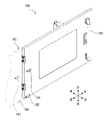
개폐도어(190)는 일 측이 케이스(180)에 힌지 결합되어 있다. 이러한 개폐도어(190)는 도 30에서와 같이 그 외면에 고정돌기(191), 피감지체(192) 및 손잡이(193)를 구비하고 있고, 도 31에서와 같이 그 내면에 상하 방향으로 긴 정렬바(194)가 구비된다.One side of the opening/
고정돌기(191)는 개폐도어(190)가 열렸을 때 케이스(180) 측에 고정되기 위해 마련되며 중단이 잘록한 형태이다.The fixing
피감지체(192)는 개폐도어(190)가 적절하게 열려 있는지를 확인하기 위한 마련된다.The
정렬바(194)는 관리자에 의해 수납장치(121)로 공급된 테스트트레이(TT)를 정렬하기 위해 마련된다. 도 32의 개략도에서와 같이 정렬바(194)는 개폐도어(190)가 제2 노출창(EW2)을 폐쇄할 때 수납장치(121)로 공급된 테스트트레이(TT)의 전단을 후방으로 밀어 무빙기(121d)에 의해 테스트트레이(TT)가 후방으로 이동될 수 있는 위치로 테스트트레이(TT)를 이동시킨다. 이를 위해 정렬바(194)는 내측으로 돌출되게 구비된다.The
한편, 고정돌기(191)와 피감지체(192)에 대응하여 케이스(180)에는 도 30에서 참조되는 바와 같이 고정기(181)와 감지기(181)가 구비된다.On the other hand, in correspondence with the fixing
도 33의 개략도에서와 같이 고정기(181)는 하우징(181a), 한 쌍의 고정볼(181b) 및 한 쌍의 탄성부재(181c)를 포함한다.As shown in the schematic diagram of FIG. 33 , the
하우징(181a)은 고정돌기(181)가 삽입되는 삽입홈(ISS)을 가지며, 고정볼(181b) 및 탄성부재(181c)를 수용한다.The
한 쌍의 고정볼(181b)은 삽입홈(ISS) 측으로 약간 돌출되도록 탄성부재(181c) 의해 탄성 지지됨으로써 삽입홈(ISS)에 삽입된 고정돌기(191)를 측방에서 탄성 가압한다.The pair of fixing
한 쌍의 탄성부재(181c)는 한 쌍의 고정볼(181b)을 삽입홈(ISS) 측으로 탄성 가압한다.The pair of
감지기(182)는 피감지체(191)를 감지함으로써 개폐도어(190)이 적절히 열려 있는지를 확인할 수 있게 한다.The
따라서 개폐도어(190)가 열려지면, 고정돌기(191)가 삽입홈(ISS)에 삽입되면서 고정볼(181b)에 의해 탄성 가압되기 때문에 개폐도어(190)가 열린 상태로 고정될 수 있다.Accordingly, when the opening/
또한, 고정돌기(191)가 고정볼(181b)에 의해 적절히 고정된 상태에서는 감지기(182)가 피감지체(1921)를 감지함으로써 개폐도어(190)가 적절히 열려 있음을 확인할 수 있게 된다.In addition, in a state in which the fixing
만일, 개폐도어(190)가 열렸음에도 감지기(182)가 피감지체(192)를 감지하지 못하면, 개폐도어(190)가 부적절하게 열려졌음을 의미하는 것이므로, 제어장치(160)는 작동불량신호를 발생시킨다.If the
참고로, 개폐도어(190)가 닫혔을 때에도 개폐도어(190)의 닫힌 상태를 감지할 수 있는 구성이 추가되는 것도 바람직하게 고려될 수 있다. For reference, even when the opening/
다음으로, 상기한 바와 같은 검사장비(100)의 전체 작동에 대하여 개략적으로 설명한다.Next, the overall operation of the
1. 설정1. Settings
(a) 관리자는 입력장치(도시되지 않음)를 이용하여 부속품(SP)에 대한 규격을 입력한 후 설정한다.(a) The manager sets the standard after inputting the specification for the accessory (SP) using an input device (not shown).
(b) 관리자는 검사장치(140)를 시험 작동시키면서 입력장치를 이용하여 검사부분, 조사각 및 빛의 색상 설정을 설정한다.(b) The manager sets the inspection part, the irradiation angle, and the color of the light by using the input device while operating the
예를 들면, 테스트트레이(TT)에 있는 인서트의 래치부분, 안내구멍, 안착홈의 불량 여부를 검사하고자 하는 경우 래치부분을 제1 검사부분, 안내구멍을 제2 검사부분, 안착홈을 제3 검사부분으로 설정한다.For example, if you want to inspect whether the latch part, guide hole, or seating groove of the insert in the test tray TT is defective, the latch part is the first inspection part, the guide hole is the second inspection part, and the seating groove is the third part. Set as inspection part.
또한, 관리자는 각 검사부분마다 최적화된 빛의 조사각과 빛의 색상을 설정한다. 여기서 빛의 조사각에 대한 설정은 특정 검사부분의 불량 여부를 확인하기에 가장 적절한 제1 조명 내지 제4 조명(141b 내지 141e) 중 어느 하나를 선택함으로써 이루어질 수 있다. 따라서 해당 특정 검사부분을 검사하고자 할 경우에는 선택된 특정 조명(141b/141c/141d/141e)이 작동하게 된다. 그리고 관리자는 해당 특정 조명이 조사할 빛의 색을 설정한다. 이 때 빛의 색에 대한 설정은 해당 특정 조명(141b/141c/141d/141e)에 구비된 다수의 광원(F1/F2/F3/F4)들 중 붉은색 빛을 조사하는 광원(예를 들면, 제1 조명의 다수의 F1 광원들 중 붉은색의 광원), 푸른색 빛을 조사하는 광원(예를 들면, 제1 조명의 다수의 F1 광원들 중 푸른색의 광원), 녹색 빛을 조사하는 광원(예를 들면, 제1 조명의 다수의 F1 광원들 중 녹색의 광원) 및 백색의 빛을 조사하는 광원(예를 들면, 제1 조명의 다수의 F1 광원들 중 백색의 광원)들의 세기를 조절함으로서 이루어질 수 있다.In addition, the manager sets the optimal light irradiation angle and light color for each inspection part. Here, the setting of the irradiation angle of light may be made by selecting any one of the first to
참고로 조사각 및 빛의 색에 대한 설정은 시험 작동 시에 관리자가 디스플레이장치(도시되지 않음)의 화면을 통해 보이는 검사부분에 대한 이미지를 보면서 불량 여부를 가장 명확히 판단할 수 있는 최적화된 상태를 확인하면서 이루어질 수 있다. For reference, the setting of the irradiation angle and the color of the light is an optimized state in which the administrator can most clearly determine whether there is a defect by looking at the image of the inspection part seen through the screen of the display device (not shown) during the test operation. This can be done while checking.
위와 같은 설정이 이루어지면, 관리자가 검사 시작 명령을 입력함으로써 검사가 수행된다. 즉, 검사장치(140)가 부속품(SP)의 상방에서 수평 방향으로 이동하면서 부속품(SP)의 평면에 대한 전체 영역을 촬영하면서 검사가 이루어진다. 이 때, 조사각 및 빛의 색은 앞서 설명한 바와 같이 검사하고자 하는 검사부분에 대해 설정된 대로 조절된다. When the above settings are made, the inspection is performed by the administrator inputting the inspection start command. That is, while the
2. 제1 노출창(EW2. First exposure window (EW) 1One )을 통해 부속품(SP)을 공급하는 경우) when supplying accessories (SP) through
관리자는 검사대상인 부속품(SP)의 개수가 소량인 경우, 직접 제1 노출창(EW1)을 통해 부속품(SP)을 지지장치(110)로 공급한 다음 검사장비(100)를 작동시킨다. 이에 따라 제어장치(160)는 이동장치(150) 및 검사장치(140)를 제어하여 부속품(SP)에 대한 1차 검사를 수행한다.When the number of accessories SP to be inspected is small, the manager directly supplies the accessories SP to the
그리고 부속품(SP)의 일 측 면에 대한 검사가 종료되면, 관리자가 부속품(SP)을 180도 회전시켜 놓은 후, 부속품(SP)에 대한 2차 검사를 수행하도록 검사장비(400)를 작동시킨다. 여기서 부속품(SP)이 테스트트레이(TT)인 경우에는 트랜스퍼장치(130)에 의해 테스트트레이(TT)를 180도 회전시켜 놓도록 구현될 수도 있다.And when the inspection on one side of the accessory (SP) is finished, the manager rotates the accessory (SP) by 180 degrees, and then operates the inspection equipment 400 to perform a secondary inspection on the accessory (SP) . Here, when the accessory SP is the test tray TT, it may be implemented to rotate the test tray TT by 180 degrees by the
차후 부속품(SP)에 대한 2차 검사까지 종료되면, 관리자는 제1 노출창(EW1)을 통해 부속품(SP)을 수거한다.After the second inspection of the accessory (SP) is finished, the manager collects the accessory (SP) through the first exposure window (EW 1 ).
3. 제2 노출창(EW3. Second exposure window (EW) 22 )을 통해 테스트트레이(TT)를 공급하는 경우) when supplying a test tray (TT) through
관리자는 개폐도어(190)를 열어서 고정시킨 후 검사장비(100)를 1차적으로 작동시킨다. 이 때, 개폐도어(190)가 부적절하게 열린 경우에는 검사장비(100)가 작동되지 않는다.The manager first operates the
개폐도어(190)가 적절하게 열린 경우, 관리자가 테스트트레이(TT)를 공급하기 편하도록 전후진장치(122)는 수납장치(121)를 전방으로 이동시킨다.When the opening/
수납장치(121)가 전방으로 이동되면, 관리자는 테스트트레이(TT)들을 수납장치(121)로 공급한다.When the
수납장치(121)로 테스트트레이(TT)들이 모두 공급되면, 관리자는 개폐도어(190)를 닫는다. 이 때, 개폐도어(190)의 정렬바(194)가 테스트트레이(TT)의 전단을 후방으로 밀기 때문에, 테스트트레이(TT)가 무빙기(121d)에 의해 후방으로 이동될 수 있는 위치로 이동하여 정렬된다.When all the test trays TT are supplied to the
관리자는 검사장비(100)를 2차적으로 작동시킨다. 만일 개폐도어(190)의 닫힘을 확인하기 위한 구성이 구비된 경우에는, 개폐도어(190)가 적절하게 닫힌 경우에만 검사장비(100)가 2차적으로 작동된다. 2차적인 작동에 따라 무빙기(121d)가 작동하여 테스트트레이(TT)들을 후방으로 이동시키고, 한편으로는 전후진장치(122)가 작동하여 수납장치(121)를 후방으로 이동시킨다. 따라서 수납장치(121)에 수납된 테스트트레이(TT)가 트랜스퍼장치(130)에 의해 파지될 수 있는 위치로 이동하게 된다.The manager operates the
위의 무빙기(121d), 전후진장치(122) 및 정렬바(194)는 설계자의 의도에 따라 모두 생략되거나 선택적으로 하나 이상이 구성될 수 있다. 그리고 상기의 장치들은 보다 효율적인 운영을 위해 서로 조화를 이룰 수도 있다.The above moving
그리고 트랜스퍼장치(130)가 작동하여 수납장치(121)에 있는 테스트트레이(TT)를 수납장치(121)의 상방에 있는 지지장치(110)로 이동시키고, 검사장치(140)와 이동장치(150)가 작동하여 테스트트레이(TT)의 상면에 대한 검사를 수행한다.Then, the
테스트트레이(TT)의 상면에 대한 검사가 종료되면, 트랜스퍼장치(130)가 작동하여 테스트트레이(TT)를 180도 회전시킨 후 테스트트레이(TT)를 지지장치(110)로 재공급한다. 이에 따라 검사장치(140)는 상방을 향하게 된 테스트트레이(TT)의 하면에 대한 검사를 수행한다.When the inspection of the upper surface of the test tray TT is finished, the
차후 테스트트레이(TT)의 하면에 대한 검사까지 종료되면, 트랜스퍼장치(130)가 작동하여 테스트트레이(TT)를 180도 회전시켜 원래의 상태로 복귀시킨 후 수납장치(121)로 이동시킨다. After the inspection of the lower surface of the test tray TT is finished, the
그리고 트랜스퍼장치(130)가 다른 테스트트레이(TT)를 지지장치(110)로 공급함으로써 다른 테스트트레이(TT)들에 대한 검사를 지속적으로 수행한다.In addition, the
한편, 수납장치(121)에 있는 모든 테스트트레이(TT)들에 대한 검사가 종료되고, 검사가 종료된 모든 테스트트레이(TT)가 수납장치(121)에 수납되면, 관리자는 개폐도어(190)를 연 다음 검사장비(100)를 3차적으로 작동시킨다. 이에 따라 무빙기(121d)가 작동하여 테스트트레이(TT)를 전방으로 이동시키고, 전후진장치(122)가 작동하여 수납장치(121)가 제2 노출창(EW2)에 인접하도록 전방으로 이동된다. 이렇게 테스트트레이(TT)와 수납장치(121)와 전방으로 이동된 상태에서 관리자는 수납장치(121)에 있는 테스트트레이(TT)를 수거한다.On the other hand, when the inspection of all the test trays TT in the
상술한 바와 같이, 본 발명에 대한 구체적인 설명은 첨부된 도면을 참조한 실시예에 의해서 이루어졌지만, 상술한 실시예는 본 발명의 바람직한 예를 들어 설명하였을 뿐이기 때문에, 본 발명이 상기한 실시예에만 국한되는 것으로 이해되어져서는 아니 되며, 본 발명의 권리범위는 후술하는 청구범위 및 그 균등범위로 이해되어져야 할 것이다.As described above, the detailed description of the present invention has been made by the embodiments with reference to the accompanying drawings, but since the above-described embodiments have only been described with preferred examples of the present invention, the present invention is limited to the above-described embodiments only. It should not be construed as being limited, and the scope of the present invention should be understood as the following claims and their equivalents.
141 : 촬영기
141a : 카메라
141b ; 제1 조명
F1 : 제1 광원
RM : 반사유리
141c : 제2 조명
F2 : 제2 광원
141d : 제3 조명
F3 : 제3 광원
141e : 제4 조명
F4 : 제4 광원
141 : camera
141a : camera
141b; first light
F 1 : first light source RM : reflective glass
141c: second light
F 2 : second light source
141d: third light
F 3 : third light source
141e: fourth light
F 4 : fourth light source
Claims (8)
상기 카메라에 결합되어서 상기 카메라와 함께 이동할 수 있으며, 검사대상물의 상면에 수직한 조사각도로 빛을 조사하는 수직 조명; 및
상기 카메라에 결합되어서 상기 카메라와 함께 이동할 수 있으며, 검사대상물의 상면에 대하여 0도 보다는 크고 90도 보다는 작은 각의 범위 내의 조사 각도로 빛을 조사하는 복수의 경사 조명; 을 포함하고,
상기 복수의 경사 조명은 조사 각도가 서로 다르며,
상기 수직 조명과 상기 복수의 경사 조명은 제어장치에 의해 각각 독립적으로 제어되는
물품 검사용 촬영기.A camera for photographing an inspection object in a vertically downward state in a state vertically upward to the upper surface of the inspection object to be inspected;
a vertical illumination coupled to the camera, capable of moving together with the camera, and irradiating light at an irradiation angle perpendicular to the upper surface of the object to be inspected; and
a plurality of oblique lights coupled to the camera and capable of moving together with the camera, irradiating light at an irradiation angle within a range of greater than 0 degrees and less than 90 degrees with respect to the upper surface of the object to be inspected; including,
The plurality of oblique lights have different irradiation angles,
The vertical lighting and the plurality of inclined lighting are each independently controlled by a control device
A camera for inspection of goods.
상기 수직 조명은 다수개의 광원을 가지며,
상기 다수개의 광원 중 적어도 하나는 나머지 광원들과 다른 색의 빛을 조사하는
물품 검사용 촬영기.The method of claim 1,
The vertical illumination has a plurality of light sources,
At least one of the plurality of light sources irradiates light of a color different from that of the other light sources.
A camera for inspection of goods.
상기 복수의 경사 조명 각각은 다수개의 광원을 가지며,
상기 다수개의 광원은 검사대상물의 상면에 평행한 가상면 상에 원의 형태로 배치되는 것을
상기 다수개의 광원 중 적어도 하나는 나머지 광원들과 다른 색의 빛을 조사하는
물품 검사용 촬영기.The method of claim 1,
Each of the plurality of inclined lights has a plurality of light sources,
The plurality of light sources are arranged in the form of a circle on a virtual surface parallel to the upper surface of the object to be inspected.
At least one of the plurality of light sources irradiates light of a color different from that of the other light sources.
A camera for inspection of goods.
검사대상물의 하방에서 상방을 향해 빛을 조사하기 위한 조명기; 를 더 포함하는
물품 검사용 촬영기.The method of claim 1,
An illuminator for irradiating light from the lower side to the upper side of the object to be inspected; further comprising
A camera for inspection of goods.
상기 조명기를 사이에 두고 승강 가능하게 구비되며, 상승하게 되면 검사대상물의 양 측 지점에서 검사대상물이 설치되는 프레임을 받치는 한 쌍의 받침판; 및
상기 한 쌍의 받침판을 승강시키는 승강원들; 을 더 포함하는
물품 검사용 촬영기.5. The method of claim 4,
a pair of support plates provided to be able to move up and down with the illuminator interposed therebetween, and to support the frame in which the object to be inspected is installed at both sides of the object when it rises; and
elevating members for elevating the pair of support plates; further comprising
A camera for inspection of goods.
상기 조명기를 수평 방향으로 이동시킴으로써 상기 조명기를 검사대상물의 하방에 위치시킬 수 있는 이동기; 를 더 포함하고,
상기 수직 조명 및 복수의 경사 조명은 수평 방향으로 이동될 수 있도록 마련되며,
상기 이동기에 의한 상기 조명기의 이동은 상기 수직 조명 및 복수의 경사 조명과 연동하는
물품 검사용 촬영기.5. The method of claim 4,
a mover capable of positioning the illuminator below the object to be inspected by moving the illuminator in a horizontal direction; further comprising,
The vertical light and the plurality of inclined lights are provided to be movable in the horizontal direction,
The movement of the illuminator by the mover is linked to the vertical lighting and a plurality of inclined lighting
A camera for inspection of goods.
상기 조명기는 백라이트유닛으로 구비되며, 상기 수직 조명 및 상기 복수의 경사 조명에 의한 검사가 불완전한 경우에 사용되는
물품 검사용 촬영기.5. The method of claim 4,
The illuminator is provided as a backlight unit, and is used when the inspection by the vertical illumination and the plurality of inclined illumination is incomplete.
A camera for inspection of goods.
검사대상물은 반도체소자를 적재하는 테스트트레이 또는 테스트트레이에 적재된 반도체소자들을 테스터 측으로 가압하기 위한 매치플레이트인
물품 검사용 촬영기.8. The method of claim 7,
The inspection object is a test tray on which semiconductor elements are loaded or a match plate for pressing semiconductor elements loaded on the test tray toward the tester.
A camera for inspection of goods.
Priority Applications (2)
| Application Number | Priority Date | Filing Date | Title |
|---|---|---|---|
| KR1020220097887A KR102620125B1 (en) | 2015-10-22 | 2022-08-05 | Photographing device for checking goods |
| KR1020230076300A KR20230091849A (en) | 2015-10-22 | 2023-06-14 | Photographing device for checking goods |
Applications Claiming Priority (3)
| Application Number | Priority Date | Filing Date | Title |
|---|---|---|---|
| KR1020150147118A KR20170046918A (en) | 2015-10-22 | 2015-10-22 | Photographing device for checking goods |
| KR1020220031588A KR20220038039A (en) | 2015-10-22 | 2022-03-14 | Photographing device for checking goods |
| KR1020220097887A KR102620125B1 (en) | 2015-10-22 | 2022-08-05 | Photographing device for checking goods |
Related Parent Applications (1)
| Application Number | Title | Priority Date | Filing Date |
|---|---|---|---|
| KR1020220031588A Division KR20220038039A (en) | 2015-10-22 | 2022-03-14 | Photographing device for checking goods |
Related Child Applications (1)
| Application Number | Title | Priority Date | Filing Date |
|---|---|---|---|
| KR1020230076300A Division KR20230091849A (en) | 2015-10-22 | 2023-06-14 | Photographing device for checking goods |
Publications (2)
| Publication Number | Publication Date |
|---|---|
| KR20220113902A true KR20220113902A (en) | 2022-08-17 |
| KR102620125B1 KR102620125B1 (en) | 2024-01-03 |
Family
ID=58743181
Family Applications (5)
| Application Number | Title | Priority Date | Filing Date |
|---|---|---|---|
| KR1020150147118A KR20170046918A (en) | 2015-10-22 | 2015-10-22 | Photographing device for checking goods |
| KR1020220031588A KR20220038039A (en) | 2015-10-22 | 2022-03-14 | Photographing device for checking goods |
| KR1020220097887A KR102620125B1 (en) | 2015-10-22 | 2022-08-05 | Photographing device for checking goods |
| KR1020230052144A KR20230057330A (en) | 2015-10-22 | 2023-04-20 | Apparatus for inspecting article |
| KR1020230076300A KR20230091849A (en) | 2015-10-22 | 2023-06-14 | Photographing device for checking goods |
Family Applications Before (2)
| Application Number | Title | Priority Date | Filing Date |
|---|---|---|---|
| KR1020150147118A KR20170046918A (en) | 2015-10-22 | 2015-10-22 | Photographing device for checking goods |
| KR1020220031588A KR20220038039A (en) | 2015-10-22 | 2022-03-14 | Photographing device for checking goods |
Family Applications After (2)
| Application Number | Title | Priority Date | Filing Date |
|---|---|---|---|
| KR1020230052144A KR20230057330A (en) | 2015-10-22 | 2023-04-20 | Apparatus for inspecting article |
| KR1020230076300A KR20230091849A (en) | 2015-10-22 | 2023-06-14 | Photographing device for checking goods |
Country Status (1)
| Country | Link |
|---|---|
| KR (5) | KR20170046918A (en) |
Citations (5)
| Publication number | Priority date | Publication date | Assignee | Title |
|---|---|---|---|---|
| JPH11242005A (en) * | 1998-12-25 | 1999-09-07 | Lion Engineerring Kk | Article appearance inspecting device |
| JP2006133052A (en) * | 2004-11-05 | 2006-05-25 | Ishizuka Glass Co Ltd | Foreign matter inspection method and device |
| JP2007064801A (en) * | 2005-08-31 | 2007-03-15 | Daiichi Jitsugyo Viswill Co Ltd | Lighting system and appearance inspection device equipped with it |
| JP2010175558A (en) * | 2010-04-01 | 2010-08-12 | Daiichi Jitsugyo Viswill Co Ltd | Inspection device |
| KR20120109473A (en) * | 2009-11-04 | 2012-10-08 | 사크미 코퍼라티브 메카니씨 이몰라 소시에타 코퍼라티바 | Apparatus, system and method for detecting defects of metallic lids |
-
2015
- 2015-10-22 KR KR1020150147118A patent/KR20170046918A/en not_active Application Discontinuation
-
2022
- 2022-03-14 KR KR1020220031588A patent/KR20220038039A/en not_active Application Discontinuation
- 2022-08-05 KR KR1020220097887A patent/KR102620125B1/en active IP Right Grant
-
2023
- 2023-04-20 KR KR1020230052144A patent/KR20230057330A/en not_active Application Discontinuation
- 2023-06-14 KR KR1020230076300A patent/KR20230091849A/en active Application Filing
Patent Citations (5)
| Publication number | Priority date | Publication date | Assignee | Title |
|---|---|---|---|---|
| JPH11242005A (en) * | 1998-12-25 | 1999-09-07 | Lion Engineerring Kk | Article appearance inspecting device |
| JP2006133052A (en) * | 2004-11-05 | 2006-05-25 | Ishizuka Glass Co Ltd | Foreign matter inspection method and device |
| JP2007064801A (en) * | 2005-08-31 | 2007-03-15 | Daiichi Jitsugyo Viswill Co Ltd | Lighting system and appearance inspection device equipped with it |
| KR20120109473A (en) * | 2009-11-04 | 2012-10-08 | 사크미 코퍼라티브 메카니씨 이몰라 소시에타 코퍼라티바 | Apparatus, system and method for detecting defects of metallic lids |
| JP2010175558A (en) * | 2010-04-01 | 2010-08-12 | Daiichi Jitsugyo Viswill Co Ltd | Inspection device |
Also Published As
| Publication number | Publication date |
|---|---|
| KR102620125B1 (en) | 2024-01-03 |
| KR20170046918A (en) | 2017-05-04 |
| KR20230057330A (en) | 2023-04-28 |
| KR20230091849A (en) | 2023-06-23 |
| KR20220038039A (en) | 2022-03-25 |
Similar Documents
| Publication | Publication Date | Title |
|---|---|---|
| KR101013573B1 (en) | Appearance inspecting method of semiconductor chip and its device | |
| CN109212282B (en) | Full-automatic probe detection platform and probe positioning module thereof | |
| KR101514409B1 (en) | Vision inspection apparatus | |
| US7746980B1 (en) | X-ray reflectometry system with multiple sample holder and individual sample lifting mechanism | |
| KR20150074288A (en) | TCO(Thermal Cut Off) Automatic welding device | |
| KR20220113902A (en) | Photographing device for checking goods | |
| TWI519798B (en) | Semiconductor component testing sorting machine and its working methods | |
| KR101674154B1 (en) | Side docking type test handler and operating method of side docking type test handler | |
| KR102485396B1 (en) | Inspection equipment for checking parts of handler | |
| CN108214416A (en) | Display panel detection workbench | |
| CN111273190A (en) | LED lamp strip check out test set | |
| TW200937552A (en) | Carrier wafer position device and examination method thereof | |
| KR101901394B1 (en) | Auto probe inspection apparatus and inspection method of organic light emmiting pannel | |
| KR101391312B1 (en) | Camera assembly for back light unit inspecting apparatus | |
| KR200332887Y1 (en) | A non-contact type framework inspaction apparatus | |
| GB2260640A (en) | Cell-size inspection device for nuclear fuel assembly | |
| KR101516333B1 (en) | TCO(Thermal Cut Off) Production apparatus and manufacturing methods | |
| KR20180088564A (en) | Themal testing apparatus for flatpanel display | |
| KR101634040B1 (en) | Inspection equipment for different kinds of cok | |
| KR102126358B1 (en) | jig apparatus for inspection | |
| KR101711111B1 (en) | Apparatus for packing and unpacking a cartridge for a wafer prober and control method therefor | |
| CN212255627U (en) | LED lamp strip check out test set | |
| CN212779863U (en) | Automatic test board of light radiation flux | |
| KR101070698B1 (en) | Led wafer tester | |
| TWI755942B (en) | Handler, tester, and testing equipment |
Legal Events
| Date | Code | Title | Description |
|---|---|---|---|
| A107 | Divisional application of patent | ||
| E902 | Notification of reason for refusal | ||
| E701 | Decision to grant or registration of patent right | ||
| GRNT | Written decision to grant |