KR20200096206A - Electronic component lead cutter - Google Patents
Electronic component lead cutter Download PDFInfo
- Publication number
- KR20200096206A KR20200096206A KR1020207010253A KR20207010253A KR20200096206A KR 20200096206 A KR20200096206 A KR 20200096206A KR 1020207010253 A KR1020207010253 A KR 1020207010253A KR 20207010253 A KR20207010253 A KR 20207010253A KR 20200096206 A KR20200096206 A KR 20200096206A
- Authority
- KR
- South Korea
- Prior art keywords
- plate
- cutter head
- electronic component
- conveyor belt
- medium plate
- Prior art date
Links
Images

Classifications
-
- B—PERFORMING OPERATIONS; TRANSPORTING
- B21—MECHANICAL METAL-WORKING WITHOUT ESSENTIALLY REMOVING MATERIAL; PUNCHING METAL
- B21F—WORKING OR PROCESSING OF METAL WIRE
- B21F11/00—Cutting wire
-
- B—PERFORMING OPERATIONS; TRANSPORTING
- B21—MECHANICAL METAL-WORKING WITHOUT ESSENTIALLY REMOVING MATERIAL; PUNCHING METAL
- B21C—MANUFACTURE OF METAL SHEETS, WIRE, RODS, TUBES OR PROFILES, OTHERWISE THAN BY ROLLING; AUXILIARY OPERATIONS USED IN CONNECTION WITH METAL-WORKING WITHOUT ESSENTIALLY REMOVING MATERIAL
- B21C51/00—Measuring, gauging, indicating, counting, or marking devices specially adapted for use in the production or manipulation of material in accordance with subclasses B21B - B21F
-
- B—PERFORMING OPERATIONS; TRANSPORTING
- B21—MECHANICAL METAL-WORKING WITHOUT ESSENTIALLY REMOVING MATERIAL; PUNCHING METAL
- B21F—WORKING OR PROCESSING OF METAL WIRE
- B21F23/00—Feeding wire in wire-working machines or apparatus
- B21F23/005—Feeding discrete lengths of wire or rod
-
- Y—GENERAL TAGGING OF NEW TECHNOLOGICAL DEVELOPMENTS; GENERAL TAGGING OF CROSS-SECTIONAL TECHNOLOGIES SPANNING OVER SEVERAL SECTIONS OF THE IPC; TECHNICAL SUBJECTS COVERED BY FORMER USPC CROSS-REFERENCE ART COLLECTIONS [XRACs] AND DIGESTS
- Y02—TECHNOLOGIES OR APPLICATIONS FOR MITIGATION OR ADAPTATION AGAINST CLIMATE CHANGE
- Y02W—CLIMATE CHANGE MITIGATION TECHNOLOGIES RELATED TO WASTEWATER TREATMENT OR WASTE MANAGEMENT
- Y02W30/00—Technologies for solid waste management
- Y02W30/50—Reuse, recycling or recovery technologies
- Y02W30/82—Recycling of waste of electrical or electronic equipment [WEEE]
Abstract
전자부품 리드커팅기는 지지판을 포함하되, 상기 지지판에는 컨베이어벨트 어셈블리, 좌우가 상대되게 설치된 왼쪽 커터헤드 및 오른쪽 커터헤드가 설치되고, 상기 컨베이어벨트 어셈블리는 앞뒤가 평행되게 설치된 실린더와 2개의 실린더에 덧씌워 설치된 고리모양 벨트체를 포함하며, 상기 왼쪽 커터헤드와 오른쪽 커터헤드 사이에 미디움 플레이트(Medium Plate)를 설치하고, 상기 고리모양 벨트체를 미디움 플레이트 밖에 덧씌워 설치하며, 상기 왼쪽 커터헤드와 오른쪽 커터헤드는 모두 제1 구동기구를 매칭하고, 상기 제1 구동기구의 작용 하에, 왼쪽 커터헤드가 미디움 플레이트의 좌측면으로 이동하고 오른쪽 커터헤드가 미디움 플레이트의 우측면으로 이동한다. 본 발명은 일회성으로 전자부품의 리드커팅을 완성하고, 생산효율을 대폭 향상하며, 작업자의 노동강도를 낮출 수 있는 장점을 가진다.The electronic component lead cutter includes a support plate, and a conveyor belt assembly, a left cutter head and a right cutter head installed opposite to each other are installed on the support plate, and the conveyor belt assembly is attached to a cylinder and two cylinders installed to be parallel to each other. It includes a ring-shaped belt body installed covered, a medium plate is installed between the left cutter head and the right cutter head, and the ring-shaped belt body is overlaid outside the medium plate, and the left cutter head and the right side All of the cutter heads match the first drive mechanism, and under the action of the first drive mechanism, the left cutter head moves to the left side of the medium plate and the right cutter head moves to the right side of the medium plate. The present invention has the advantage of completing lead cutting of electronic components in one-time, greatly improving production efficiency, and lowering the labor intensity of workers.
Description
본 발명은 전자부품 리드커팅기에 관한 것이다.The present invention relates to an electronic component lead cutter.
전자부품은 구매한 후, 수요에 따라 일정한 정도로 리드 커팅해야 하는 데, 핀(pin)에 초점을 맞추어 한 줄 내외의 간격을 두고 설치된 전자부품은 전단기를 이용해 일회성으로 한 줄의 모든 핀을 리드 커팅하지만, 도 1에 도시된 바와 같이, 핀이 2열로 여러 줄 늘어선 전자부품은 전단기를 이용해 일회성으로 리드 커팅을 완성할 수 없어, 전단기를 여러 번 사용해야 하므로, 효율이 비교적 낮다.After purchasing electronic components, lead-cut to a certain degree is required according to the demand. Electronic components installed with an interval of about one row or less focusing on the pin are lead-cutting all pins in one row at a time using a shearing machine. However, as shown in FIG. 1, the electronic component in which the pins are arranged in two rows in several rows cannot be lead cut once using a shearing machine, and thus the shearing machine must be used several times, and thus the efficiency is relatively low.
본 발명의 목적은 전자부품을 전단해 생산효율을 향상시킬 수 있는 전자부품 리드커팅기를 제공하는 데 있다.An object of the present invention is to provide an electronic component lead cutter capable of improving production efficiency by shearing electronic components.
상기 목적을 달성하기 위해, 본 발명은 아래 기술방안을 이용한다. 지지판을 포함하되, 상기 지지판에는 컨베이어벨트 어셈블리, 좌우가 상대되게 설치된 왼쪽 커터헤드 및 오른쪽 커터헤드가 설치되고, 상기 컨베이어벨트 어셈블리는 앞뒤가 평행되게 설치된 실린더와 2개의 실린더에 덧씌워 설치된 고리모양 벨트체를 포함하며, 상기 왼쪽 커터헤드와 오른쪽 커터헤드 사이에 미디움 플레이트(Medium Plate)를 설치하고, 상기 고리모양 벨트체를 미디움 플레이트 밖에 덧씌워 설치하며, 상기 왼쪽 커터헤드와 오른쪽 커터헤드는 모두 제1 구동기구를 매칭하고, 상기 제1 구동기구의 작용 하에, 왼쪽 커터헤드가 미디움 플레이트의 좌측면으로 이동하고 오른쪽 커터헤드가 미디움 플레이트의 우측면으로 이동하는 것을 특징으로 하는 전자부품 리드커팅기를 제공한다.In order to achieve the above object, the present invention uses the following technical solutions. Including a support plate, the support plate has a conveyor belt assembly, a left cutter head and a right cutter head installed opposite to each other, and the conveyor belt assembly is a cylinder installed in parallel with front and rear and an annular belt installed overlaid on two cylinders. It includes a sieve, and a medium plate is installed between the left cutter head and the right cutter head, and the ring-shaped belt body is covered outside the medium plate, and the left and right cutter heads are all manufactured. 1 Matching the driving mechanism, and under the action of the first driving mechanism, it provides an electronic component lead cutter, characterized in that the left cutter head moves to the left side of the medium plate and the right cutter head moves to the right side of the medium plate. .
본 발명에 따른 리드커팅기를 사용할 때, 전자부품을 컨베이어벨트 어셈블리의 고리모양 벨트체 상단면에 설치해 전자부품의 프레임이 고리모양 벨트체에 지지되도록 함으로써, 전자부품 좌우 양측의 핀(pin)이 각각 고리모양 벨트체의 좌우측에 위치하도록 한 다음, 고리모양 벨트체가 이동하도록 해 전자부품을 좌우측 커터헤드 사이까지 움직인다. 이때, 전자부품의 좌측의 핀이 미디움 플레이트과 왼쪽 커터헤드 사이에 위치하고, 전자부품의 우측의 핀이 미디움 플레이트와 오른쪽 커터헤드 사이에 위치하며, 제1 구동기구를 가동해 리드커팅 작업을 완성한 다음, 고리모양 벨트체가 계속 이동해 리드커팅이 완성된 전자부품을 언로딩단까지 이동한다. 본 발명에 따른 리드커팅기는 전자부품의 리드커팅을 일회성으로 완성해 생산효율을 대폭 향상시키고 작업자의 노동 강도를 낮출 수 있다.When using the lead cutter according to the present invention, the electronic component is installed on the top surface of the annular belt body of the conveyor belt assembly so that the frame of the electronic component is supported by the annular belt body, so that pins on the left and right sides of the electronic component are respectively It is positioned on the left and right sides of the annular belt body, and then the annular belt body is moved to move the electronic component between the left and right cutter heads. At this time, the pin on the left side of the electronic component is located between the medium plate and the left cutter head, the pin on the right side of the electronic component is located between the medium plate and the right cutter head, and the first driving mechanism is operated to complete the lead cutting operation. The ring-shaped belt body continues to move to move the electronic component that has been lead cut to the unloading end. The lead cutter according to the present invention can significantly improve the production efficiency and lower the labor intensity of workers by completing the lead cutting of electronic components in one time.
바람직하게, 상기 컨베이어벨트 어셈블리는 승강판 상측에 고정하고, 상기 승강판은 제2 구동기구를 결합하며, 상기 제2 구동기구의 작용 하에, 상기 컨베이어벨트 어셈블리는 미디움 플레이트에 상대되게 상하이동한다. 여기에서, 전자부품핀 길이가 다른 수요에 근거해, 본 발명은 리드커팅 길이를 조절할 수 있도록 높이가 다른 승강판을 선택한다.Preferably, the conveyor belt assembly is fixed to the upper side of the elevator plate, the elevator plate engages a second driving mechanism, and under the action of the second driving mechanism, the conveyor belt assembly moves upward and upward relative to the medium plate. Here, based on the demand for different electronic component pin lengths, the present invention selects an elevator plate having a different height so that the lead cutting length can be adjusted.
바람직하게, 상기 지지판에 수직판을 설치하고, 상기 수직판에는 좌우방향을 따라 설치된 가로판을 견고하게 구비하며, 상기 가로판 상단면은 아래로 함몰되어 앞뒤로 관통된 고정홈을 가지고, 상기 미디움 플레이트는 상기 고정홈 내에 고정되며, 상기 가로판은 왼쪽 커터헤드와 오른쪽 커터헤드의 앞측과 뒤측에 위치한다. 상기 설치는 미디움 플레이트의 지지 효과가 더 우수해 지도록 함으로써, 미디움 플레이트가 좌우로 흔들리는 것을 방지해 리드커팅 효과를 확보한다.Preferably, a vertical plate is installed on the support plate, and a horizontal plate installed along the left and right directions is firmly provided on the vertical plate, and the upper surface of the horizontal plate has a fixing groove recessed downward and penetrating back and forth, and the medium plate Is fixed in the fixing groove, and the horizontal plate is located at the front and rear sides of the left and right cutter heads. The above installation ensures a better support effect of the medium plate, thereby preventing the medium plate from shaking from side to side to secure a lead cutting effect.
바람직하게, 상기 미디움 플레이트의 일단은 컨베이어벨트 어셈블리의 로딩단까지 연장되며, 상기 미디움 플레이트는 로딩단의 일단에 위치해 로딩단부터 언로딩단 측까지의 폭이 점점 커지는 구조를 이룬다. 미디움 플레이트는 전자부품이 이동할 때의 가이드로도 사용할 수 있다.Preferably, one end of the medium plate extends to the loading end of the conveyor belt assembly, and the medium plate is positioned at one end of the loading end to form a structure in which the width from the loading end to the unloading end is gradually increased. The medium plate can also be used as a guide for moving electronic parts.
바람직하게, 상기 컨베이어벨트 어셈블리 측에는 검출센서가 설치되고, 상기 검출센서는 왼쪽 커터헤드와 오른쪽 커터헤드의 앞측에 위치하며, 검출센서가 고리모양 벨트체에 전자부품이 구비된 것을 검출하였을 경우, 제1 구동기구는 aS후에 작동한다. 정시 계전기를 설치해 aS 지연하며, 검출센서는 적외선 수신센서를 선택할 수 있고 기타 위치검출센서를 사용할 수도 있다.Preferably, a detection sensor is installed on the conveyor belt assembly side, the detection sensor is located in front of the left and right cutter heads, and when the detection sensor detects that an electronic component is provided in the
바람직하게, 상기 제2 구동기구는 구동모터와 리드스크루를 포함하고, 상기 리드스크루는 회전해 상기 승강판이 상향 또는 하향 이동하도록 하며, 상기 승강판에 나사산 블록을 고정하고, 상기 나사산 블록과 리드스크루는 나사산으로 매칭되며, 상기 승강판에 다수의 가이드 블록을 설치하고, 상기 지지판에 다수의 가이드 포스트를 설치하며, 상기 승강판과 가이드 블록에는 가이드 포스트와 서로 매칭되는 가이드 홀이 설치된다. 리드스크루를 사용해 승강판을 상하승강하도록 하고, 정밀도가 더 높아 리드커팅 효과가 더 우수해지게 된다.Preferably, the second driving mechanism includes a driving motor and a lead screw, and the lead screw rotates so that the elevator plate moves upward or downward, fixes a thread block to the elevator plate, and fixes the thread block and the lead screw. Is matched with a screw thread, a plurality of guide blocks are installed on the elevator plate, a plurality of guide posts are installed on the support plate, and guide holes matching with the guide posts are installed in the elevator plate and the guide block. A lead screw is used to move the elevator plate up and down, and the lead cutting effect is better with higher precision.
바람직하게, 상기 지지판에 엔클로저(encloser)를 설치하고, 상기 엔클로저는 적어도 고리모양 벨트체 상측에 위치한 프레스보드(pressboard)를 포함하며, 상기 프레스보드와 고리모양 벨트체 상단면 간에는 전자부품 프레임을 통과시키는 공간이 구비된다. 프레스보드는 전자부품이 이동할 때 튕기는 것을 방지하는 데 사용한다.Preferably, an enclosure is installed on the support plate, and the enclosure includes at least a pressboard located above the annular belt body, and the electronic component frame passes between the press board and the upper end of the annular belt body. Space is provided. Press boards are used to prevent electronic parts from bouncing when moving.
바람직하게, 상기 지지판에는 왼쪽 커터헤드와 오른쪽 커터헤드 하방에 위치한 부위에 상대되게 상하로 관통된 통과홈이 설치되고, 상기 통과홈 하측에 폐기물 수집함이 설치된다. 폐기물 수집함은 잘린 핀을 수집하는 데 사용한다.Preferably, the support plate is provided with a through groove penetrating up and down relative to a portion located below the left cutter head and the right cutter head, and a waste collection bin is installed under the passage groove. Waste collection bins are used to collect cut pins.
본 발명은 일회성으로 전자부품의 리드커팅을 완성하고, 생산효율을 대폭 향상하며, 작업자의 노동강도를 낮출 수 있는 장점을 가진다.The present invention has the advantage of completing lead cutting of electronic components in one-time, greatly improving production efficiency, and lowering the labor intensity of workers.
도 1은 본 발명의 구조 예시도이고;
도 2는 본 발명의 단면도이고;
도 3은 본 발명의 또 다른 구조 예시도이다.1 is a schematic structural diagram of the present invention;
2 is a cross-sectional view of the present invention;
Figure 3 is another exemplary structure of the present invention.
이하, 도면과 구체적인 실시예에 근거해 본 발명을 더 상세히 설명한다.Hereinafter, the present invention will be described in more detail based on the drawings and specific embodiments.
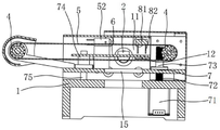
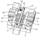
도 1, 도 2와 도 3에서 도시하는 바와 같이, 본 발명에 따른 전자부품 리드커팅기는 지지판(1)과 엔클로저를 포함하고, 지지판(1)에 컨베이어벨트 어셈블리, 좌우가 상대되게 설치된 왼쪽 커터헤드(2)와 오른쪽 커터헤드(3)를 설치하며, 왼쪽 커터헤드(2)와 오른쪽 커터헤드(3)는 전자부품(8)의 핀(pin)(82)을 자르는 데 사용하고, 컨베이어벨트 어셈블리는 앞뒤로 평행되게 설치된 실린더(4)와 2개의 실린더(4)에 덧씌워 설치된 고리모양 벨트체(5)를 포함하며, 왼쪽 커터헤드(2)와 오른쪽 커터헤드(3) 사이에 미디움 플레이트(Medium Plate)(6)를 설치하고, 고리모양 벨트체(5)는 미디움 플레이트(6) 밖에 덧씌워 설치되며, 왼쪽 커터헤드(2)와 오른쪽 커터헤드(3)는 모두 제1 구동기구(20)를 매칭하고, 제1 구동기구(20)의 작용 하에, 왼쪽 커터헤드(2)는 미디움 플레이트(6)의 좌측면으로 이동하되, 오른쪽 커터헤드(3)는 미디움 플레이트(6)의 우측면으로 이동한다. 여기에서, 제1 구동기구(20)는 실린더이며, 컨베이어벨트 어셈블리의 실린더(4)는 컨베이어벨트 모터(41)에 의해 구동된다. 엔클로저는 적어도 고리모양 벨트체(5) 상측에 위치한 프레스보드(13)를 포함하고, 프레스보드(13)와 고리모양 벨트체(5) 상단면 간에 전자부품(8)의 프레임(81)을 통과시키는 공간이 구비된다.1, 2 and 3, the electronic component lead cutter according to the present invention includes a
컨베이어벨트 어셈블리의 앞측의 실린더는 엔클로저 밖에 위치하고, 고리모양 벨트체(5)는 일부가 엔클로저 밖에 노출되어 로딩단을 형성하며, 고리모양 벨트체(5)가 엔클로저 내에 위치하는 일단은 방출단이고, 지지판에 공작물 수집함을 설치할 수 있으며,엔클로저 뒤측을 열어 작업자가 수동으로 언로딩하도록 할 수도 있다. 지지판(1)에는 왼쪽 커터헤드(2)와 오른쪽 커터헤드(3) 하방에 위치한 부위에 상대되게 상하로 관통된 통과홈(15)이 설치되고, 통과홈 하측에 폐기물 수집함이 설치된다.The cylinder at the front side of the conveyor belt assembly is located outside the enclosure, the
컨베이어벨트 어셈블리는 승강판(7) 상측에 고정하고, 승강판(7)은 제2 구동기구를 결합하며, 제2 구동기구의 작용 하에, 컨베이어벨트 어셈블리는 미디움 플레이트(6)에 상대되게 상하이동한다. 제2 구동기구는 구동모터(71)와 리드스크루(72)를 포함하고, 리드스크루(72)는 회전해 승강판(7)이 상향 또는 하향 이동하도록 하며, 승강판(7)에 나사산 블록(73)을 고정하고, 나사산 블록(73)과 리드스크루(72)는 나사산으로 매칭되며, 승강판(7)에 다수개의 가이드 블록(74)을 설치하고, 지지판(7)에 다수개의 가이드 포스트(75)를 설치하며, 승강판(7)과 가이드 블록(74)에는 가이드 포스트(75)과 서로 매칭되는 가이드 홀이 설치된다.The conveyor belt assembly is fixed to the upper side of the elevator plate 7, and the elevator plate 7 couples the second driving mechanism, and under the action of the second driving mechanism, the conveyor belt assembly moves upward relative to the
지지판(1)에는 2개가 좌우로 평행되게 설치된 수직판(11)이 설치되고, 각각의 제1 구동기구(20)는 모두 하나의 수직판(11)과 고정되며, 왼쪽의 수직판에 좌우방향을 따라 설치된 가로판(12)을 견고하게 구비하고, 가로판(12) 상단면은 아래로 함몰되어 앞뒤로 관통된 고정홈을 구비하며, 미디움 플레이트(6)는 죔쇠를 통해 고정홈 내에 고정되고, 가로판(12)은 왼쪽 커터헤드(2)와 오른쪽 커터헤드(3)의 뒤측에 위치한다.The
미디움 플레이트(6)의 일단은 컨베이어벨트 어셈블리의 로딩단까지 연장되고, 미디움 플레이트(6)는 로딩단의 일단에 위치해 로딩단부터 언로딩단 측까지의 폭이 점점 커지는 구조를 이룬다. 컨베이어벨트 어셈블리 측에 검출센서를 설치하고, 검출센서는 왼쪽 커터헤드(2)와 오른쪽 커터헤드(3)의 앞측에 위치하며, 검출센서가 고리모양 벨트체(5)에 전자부품이 구비된 것을 검출하였을 경우, 제1 구동기구(20)는 aS후에 작동한다. 검출센서는 적외선센서이며, 적외선 수신센서(51)와 적외선 발사센서(52)를 포함한다.One end of the
본 발명에 따른 리드커팅기를 사용할 때, 전자부품을 컨베이어벨트 어셈블리의 고리모양 벨트체 상단면에 설치해 전자부품의 프레임이 고리모양 벨트체에 지지되도록 함으로써, 전자부품 좌우 양측의 핀이 각각 고리모양 벨트체의 좌우측에 위치하도록 한 다음, 고리모양 벨트체가 이동함에 따라, 검출센서가 전자부품을 검출한 후, aS 지연하고(고리모양 벨트체의 이동 속도에 근거해 지연 시간을 확정함), 2개의 제1 구동기구가 작동함으로써, 전자부품을 왼쪽 오른쪽 커터헤드 사이까지 움직이는 데, 이때, 전자부품의 왼쪽의 핀이 미디움 플레이트와 왼쪽 커터헤드 사이에 위치하고, 전자부품의 오른쪽의 핀이 미디움 플레이트와 오른쪽 커터헤드 사이에 위치하며, 리드커팅할 수 있도록 좌우측 커터헤드가 이동하고, 리드커팅이 완성된 전자부품은 계속 뒤로 이동해 공작물 수집함에 떨어진다. 여기에서, 수요에 따라 제2 구동기구를 통해 승강판에서 컨베이어벨트 어셈블리의 상하이동을 구현함으로써, 고리모양 벨트체 상단면부터 미디움 플레이트 간의 거리를 조정해 리드커팅 길이를 조절한다.When using the lead cutter according to the present invention, the electronic component is installed on the top surface of the annular belt body of the conveyor belt assembly so that the frame of the electronic component is supported by the annular belt body. After positioning it on the left and right sides of the sieve, as the annular belt body moves, the detection sensor detects the electronic component and then delays aS (determining the delay time based on the moving speed of the annular belt body). The first driving mechanism moves the electronic component to the left and right cutter heads. At this time, the left pin of the electronic component is located between the medium plate and the left cutter head, and the right pin of the electronic component is the medium plate and the right side. It is located between the cutter heads, and the left and right cutter heads move to enable lead-cutting, and the electronic component that has been lead-cutting continues to move backwards and falls into the workpiece collection box. Here, by implementing the vertical movement of the conveyor belt assembly from the elevator plate through the second driving mechanism according to demand, the lead cutting length is adjusted by adjusting the distance between the medium plate from the top surface of the annular belt body.
본 발명에 따른 리드커팅기는 일회성으로 전자부품의 리드커팅을 완성하고, 생산효율을 대폭 향상하며, 작업자의 노동강도를 낮출 수 있다.The lead cutter according to the present invention can complete lead cutting of electronic components in one time, significantly improve production efficiency, and lower the labor intensity of workers.
Claims (8)
상기 컨베이어벨트 어셈블리는 승강판 상측에 고정하고, 상기 승강판은 제2 구동기구를 결합하며, 상기 제2 구동기구의 작용 하에, 상기 컨베이어벨트 어셈블리는 미디움 플레이트에 상대되게 상하이동하는 것을 특징으로 하는 전자부품 리드커팅기.The method of claim 1,
The conveyor belt assembly is fixed to the upper side of the elevator plate, the elevator plate couples a second driving mechanism, and under the action of the second driving mechanism, the conveyor belt assembly moves up and down relative to the medium plate. Electronic component lead cutter.
상기 지지판에 수직판을 설치하고, 상기 수직판에는 좌우방향을 따라 설치된 가로판을 견고하게 구비하며, 상기 가로판 상단면은 아래로 함몰되어 앞뒤로 관통된 고정홈을 가지고, 상기 미디움 플레이트는 상기 고정홈 내에 고정되며, 상기 가로판은 왼쪽 커터헤드와 오른쪽 커터헤드의 앞측과 뒤측에 위치하는 것을 특징으로 하는 전자부품 리드커팅기.According to claim 2,
A vertical plate is installed on the support plate, and a horizontal plate installed along the left and right direction is firmly provided on the vertical plate, and the upper surface of the horizontal plate has a fixing groove recessed downward and penetrating back and forth, and the medium plate is fixed to the An electronic component lead cutter, wherein the horizontal plate is fixed in the groove, and wherein the horizontal plate is located at front and rear sides of a left cutter head and a right cutter head.
상기 미디움 플레이트의 일단은 컨베이어벨트 어셈블리의 로딩단까지 연장되며, 상기 미디움 플레이트는 로딩단의 일단에 위치해 로딩단부터 언로딩단 측까지의 폭이 점점 커지는 구조를 이루는 것을 특징으로 하는 전자부품 리드커팅기.The method of claim 1,
One end of the medium plate extends to the loading end of the conveyor belt assembly, and the medium plate is positioned at one end of the loading end to form a structure in which the width from the loading end to the unloading end increases gradually. .
상기 컨베이어벨트 어셈블리 측에는 검출센서가 설치되고, 상기 검출센서는 왼쪽 커터헤드와 오른쪽 커터헤드의 앞측에 위치하며, 검출센서가 고리모양 벨트체에 전자부품이 구비된 것을 검출하였을 경우, 제1 구동기구는 aS후에 작동하는 것을 특징으로 하는 전자부품 리드커팅기.The method of claim 1,
A detection sensor is installed at the side of the conveyor belt assembly, the detection sensor is located in front of the left and right cutter heads, and when the detection sensor detects that an electronic component is provided in the annular belt body, a first driving mechanism Electronic component lead cutter, characterized in that the operation after aS.
상기 제2 구동기구는 구동모터와 리드스크루를 포함하고, 상기 리드스크루는 회전해 상기 승강판이 상향 또는 하향 이동하도록 하며, 상기 승강판에 나사산 블록을 고정하고, 상기 나사산 블록과 리드스크루는 나사산으로 매칭되며, 상기 승강판에 다수의 가이드 블록을 설치하고, 상기 지지판에 다수의 가이드 포스트를 설치하며, 상기 승강판과 가이드 블록에는 가이드 포스트와 서로 매칭되는 가이드 홀이 설치되는 것을 특징으로 하는 전자부품 리드커팅기.According to claim 2,
The second driving mechanism includes a driving motor and a lead screw, and the lead screw rotates to move the elevator plate upward or downward, and fixes a thread block to the elevator plate, and the thread block and the lead screw are threaded. An electronic component, characterized in that a plurality of guide blocks are installed on the elevator plate, a plurality of guide posts are installed on the support plate, and guide holes matched with the guide posts are installed in the elevator plate and the guide block. Lead cutter.
상기 지지판에 엔클로저(encloser)를 설치하고, 상기 엔클로저는 적어도 고리모양 벨트체 상측에 위치한 프레스보드(pressboard)를 포함하며, 상기 프레스보드와 고리모양 벨트체 상단면 간에는 전자부품 프레임을 통과시키는 공간이 구비되는 것을 특징으로 하는 전자부품 리드커팅기.The method of claim 1,
An enclosure is installed on the support plate, and the enclosure includes at least a pressboard located on the upper side of the annular belt body, and a space through which the electronic component frame passes between the press board and the upper surface of the annular belt body Electronic component lead cutter, characterized in that provided.
상기 지지판에는 왼쪽 커터헤드와 오른쪽 커터헤드 하방에 위치한 부위에 상대되게 상하로 관통된 통과홈이 설치되고, 상기 통과홈 하측에 폐기물 수집함이 설치되는 것을 특징으로 하는 전자부품 리드커팅기.The method of claim 1,
The electronic component lead cutter, characterized in that the support plate is provided with passage grooves penetrating vertically to correspond to portions located below the left cutter head and the right cutter head, and a waste collection bin is installed below the passage groove.
Applications Claiming Priority (3)
| Application Number | Priority Date | Filing Date | Title |
|---|---|---|---|
| CN201910091174.6 | 2019-01-30 | ||
| CN201910091174.6A CN109692925B (en) | 2019-01-30 | 2019-01-30 | Electronic component pin shearing machine |
| PCT/CN2019/098275 WO2020078065A1 (en) | 2019-01-30 | 2019-07-30 | Pin-cutting machine for electronic components |
Publications (2)
| Publication Number | Publication Date |
|---|---|
| KR20200096206A true KR20200096206A (en) | 2020-08-11 |
| KR102405980B1 KR102405980B1 (en) | 2022-06-07 |
Family
ID=66234654
Family Applications (1)
| Application Number | Title | Priority Date | Filing Date |
|---|---|---|---|
| KR1020207010253A KR102405980B1 (en) | 2019-01-30 | 2019-07-30 | Electronic Component Lead Cutting Machine |
Country Status (3)
| Country | Link |
|---|---|
| KR (1) | KR102405980B1 (en) |
| CN (1) | CN109692925B (en) |
| WO (1) | WO2020078065A1 (en) |
Cited By (1)
| Publication number | Priority date | Publication date | Assignee | Title |
|---|---|---|---|---|
| CN114029424A (en) * | 2021-10-21 | 2022-02-11 | 先之科半导体科技(东莞)有限公司 | Pin shearing device of high-power field effect transistor |
Families Citing this family (6)
| Publication number | Priority date | Publication date | Assignee | Title |
|---|---|---|---|---|
| CN109692925B (en) * | 2019-01-30 | 2024-04-26 | 浙江联宜电机有限公司 | Electronic component pin shearing machine |
| CN111482534B (en) * | 2020-04-07 | 2022-09-27 | 上海浦壹电子科技有限公司 | Component pin shearing device capable of adjusting pin shearing length |
| CN113333640A (en) * | 2021-06-08 | 2021-09-03 | 鑫创鑫自动化设备科技(漳州)有限公司 | Intelligence plug-in components feeder |
| CN113996730B (en) * | 2021-09-24 | 2024-02-02 | 深圳市万芯时代贸易有限公司 | Color ring resistor stitch trimming and collecting clamp for PCBA workshop |
| CN114210884B (en) * | 2021-11-29 | 2022-11-18 | 江西德尔诚半导体有限公司 | Pin cutting device for diode production |
| CN114289640B (en) * | 2021-12-28 | 2022-07-05 | 长春财经学院 | Computer motherboard handles with cutting foot machine based on artificial intelligence |
Citations (2)
| Publication number | Priority date | Publication date | Assignee | Title |
|---|---|---|---|---|
| KR20130060559A (en) * | 2011-11-30 | 2013-06-10 | 함승호 | Apparatus for cutting the wire |
| CN208033522U (en) * | 2018-01-30 | 2018-11-02 | 深圳市星迅电子科技有限公司 | A kind of IPM pinrshapes |
Family Cites Families (26)
| Publication number | Priority date | Publication date | Assignee | Title |
|---|---|---|---|---|
| JP2689001B2 (en) * | 1989-11-10 | 1997-12-10 | ローム株式会社 | Wire rod manufacturing device and pinning device |
| JP3503320B2 (en) * | 1996-01-10 | 2004-03-02 | 松下電器産業株式会社 | Electronic component lead wire cutting device |
| JP2004335935A (en) * | 2003-05-12 | 2004-11-25 | Fuji Electric Holdings Co Ltd | Method for replacing electronic component with lead retained by taping and automatic replacing device |
| CN201126760Y (en) * | 2007-11-12 | 2008-10-01 | 珠海华冠电子科技有限公司 | Capacitor feet-regulating apparatus |
| CN102554074B (en) * | 2012-01-12 | 2014-10-22 | 东莞市新泽谷机械制造股份有限公司 | Device for cutting vertical element pin short |
| CN204262248U (en) * | 2014-10-27 | 2015-04-15 | 苍南凯迪电气有限公司 | For the cutter of circuit board cutting |
| CN105810458A (en) * | 2014-12-29 | 2016-07-27 | 重庆同佳电子科技有限公司 | Automatic capacitor leg cutting machine |
| CN105810457A (en) * | 2014-12-29 | 2016-07-27 | 重庆同佳电子科技有限公司 | Capacitor leg cutting machine with pin detection |
| CN205236874U (en) * | 2015-11-18 | 2016-05-18 | 湖北精创电子有限公司 | Automatic pin cutting machine for LED lamp |
| CN106424468B (en) * | 2016-08-26 | 2018-08-31 | 惠州攸特电子股份有限公司 | A kind of automatic pin cutter for network transformer |
| CN206122597U (en) * | 2016-09-27 | 2017-04-26 | 福建农林大学 | Resistance pin cutting device |
| CN106311938A (en) * | 2016-10-19 | 2017-01-11 | 东莞市德速达精密设备有限公司 | Horizontal feeding device for electronic component tape |
| CN206535970U (en) * | 2016-11-16 | 2017-10-03 | 东莞市奥海电源科技有限公司 | The two-way cutter of electric capacity, resistance element |
| CN206305356U (en) * | 2016-11-30 | 2017-07-07 | 中山市华电自动化设备有限公司 | A kind of electronic component pinrshape |
| CN206997632U (en) * | 2017-03-10 | 2018-02-13 | 东莞全科姆自动化技术有限公司 | The automatic pinrshape of pcb board |
| JP6239800B1 (en) * | 2017-06-28 | 2017-11-29 | 旭精機工業株式会社 | Wire forming machine |
| CN206981648U (en) * | 2017-07-11 | 2018-02-09 | 象山佐页源电器有限公司 | Apparatus for correcting for transformer lead pin |
| CN207288742U (en) * | 2017-08-16 | 2018-05-01 | 成都禹港科技有限公司 | A kind of electronic equipment wiring board foot cut device |
| CN207205110U (en) * | 2017-09-21 | 2018-04-10 | 东莞市展荣电子设备有限公司 | A kind of electronic component material pin shaping, pinrshape |
| CN207611746U (en) * | 2017-11-14 | 2018-07-13 | 四川电科安信科技有限公司 | A kind of full-automatic encapsulation chip pin section straightening |
| CN107999672A (en) * | 2018-01-17 | 2018-05-08 | 天津九安医疗电子股份有限公司 | A kind of band-type electronic automatic pin cutter |
| CN108856590A (en) * | 2018-06-20 | 2018-11-23 | 佛山市程显科技有限公司 | A kind of pinrshape structure of pinrshape |
| CN109079055B (en) * | 2018-07-08 | 2020-01-17 | 广州市晟阳金属制品有限公司 | Terminal shaping equipment with improved structure |
| CN108889882A (en) * | 2018-07-10 | 2018-11-27 | 如皋市汇金电子科技有限公司 | A kind of circuit board connecting pins shear |
| CN109692925B (en) * | 2019-01-30 | 2024-04-26 | 浙江联宜电机有限公司 | Electronic component pin shearing machine |
| CN209792487U (en) * | 2019-01-30 | 2019-12-17 | 横店集团英洛华电气有限公司 | Electronic components cuts foot machine |
-
2019
- 2019-01-30 CN CN201910091174.6A patent/CN109692925B/en active Active
- 2019-07-30 WO PCT/CN2019/098275 patent/WO2020078065A1/en active Application Filing
- 2019-07-30 KR KR1020207010253A patent/KR102405980B1/en active IP Right Grant
Patent Citations (2)
| Publication number | Priority date | Publication date | Assignee | Title |
|---|---|---|---|---|
| KR20130060559A (en) * | 2011-11-30 | 2013-06-10 | 함승호 | Apparatus for cutting the wire |
| CN208033522U (en) * | 2018-01-30 | 2018-11-02 | 深圳市星迅电子科技有限公司 | A kind of IPM pinrshapes |
Cited By (2)
| Publication number | Priority date | Publication date | Assignee | Title |
|---|---|---|---|---|
| CN114029424A (en) * | 2021-10-21 | 2022-02-11 | 先之科半导体科技(东莞)有限公司 | Pin shearing device of high-power field effect transistor |
| CN114029424B (en) * | 2021-10-21 | 2022-08-09 | 先之科半导体科技(东莞)有限公司 | Pin shearing device of high-power field effect transistor |
Also Published As
| Publication number | Publication date |
|---|---|
| CN109692925B (en) | 2024-04-26 |
| WO2020078065A1 (en) | 2020-04-23 |
| NZ764130A (en) | 2023-09-29 |
| KR102405980B1 (en) | 2022-06-07 |
| CN109692925A (en) | 2019-04-30 |
Similar Documents
| Publication | Publication Date | Title |
|---|---|---|
| KR20200096206A (en) | Electronic component lead cutter | |
| CN109573565B (en) | Automatic plate thickness measuring machine | |
| CN106526451B (en) | Automatic circuit board detector | |
| CN110587023A (en) | Machining center for 45-degree-angle automatic cutting of single door and window aluminum-plastic profiles | |
| CN110773982B (en) | Small module assembling machine | |
| CN208230777U (en) | A kind of High Precision Automatic drift bolt riveting set | |
| CN104493292A (en) | Saw cutting device with rectangular feed manner and machining method thereof | |
| CN110329747B (en) | Method for sorting parts and sorting equipment for implementing method | |
| KR101581590B1 (en) | apparatus of manufacturing deck plate | |
| US20040144447A1 (en) | Veneer-slicing machine | |
| CN110653302A (en) | Riveting machine with self-checking function | |
| CN104972528A (en) | Novel automatic tenoning machine | |
| CN109093058A (en) | A kind of transmission chain continous way disconnecting device | |
| CN209792487U (en) | Electronic components cuts foot machine | |
| CN213055177U (en) | Batten sawing device | |
| CN214641317U (en) | Welding pressing device and welding equipment | |
| CN111604677A (en) | Circuit breaker terminal rigging equipment | |
| KR101218142B1 (en) | guide apparatus for wood manufacturing | |
| CN112122643A (en) | Numerical control automatic feeding double-row drilling machine | |
| CN110180794A (en) | A kind of detection machine of automatic measurement magnetic shoe middle part wall thickness | |
| KR101858956B1 (en) | device for piece distribution | |
| KR101620844B1 (en) | Apparatus for cutting assembly groove in window frame | |
| CN206779607U (en) | Copper piece screens beveler | |
| DE102013002762A1 (en) | Method for monitoring and optimizing terminal edges of elongated, rod-shaped wooden blocks as laths, involves monitoring end edges with line or area scan camera, and image processing single and moving images | |
| CN218428868U (en) | Positioning and drilling device for wood board processing |
Legal Events
| Date | Code | Title | Description |
|---|---|---|---|
| E902 | Notification of reason for refusal | ||
| E701 | Decision to grant or registration of patent right | ||
| GRNT | Written decision to grant |