KR20200091960A - Secondary battery positive electrode active material, secondary battery positive electrode, secondary battery, battery pack, electric vehicle, electric power storage system, electric tool, and electronic apparatus - Google Patents
Secondary battery positive electrode active material, secondary battery positive electrode, secondary battery, battery pack, electric vehicle, electric power storage system, electric tool, and electronic apparatus Download PDFInfo
- Publication number
- KR20200091960A KR20200091960A KR1020207021613A KR20207021613A KR20200091960A KR 20200091960 A KR20200091960 A KR 20200091960A KR 1020207021613 A KR1020207021613 A KR 1020207021613A KR 20207021613 A KR20207021613 A KR 20207021613A KR 20200091960 A KR20200091960 A KR 20200091960A
- Authority
- KR
- South Korea
- Prior art keywords
- positive electrode
- active material
- electrode active
- satisfies
- secondary battery
- Prior art date
Links
Images


Classifications
-
- H—ELECTRICITY
- H01—ELECTRIC ELEMENTS
- H01M—PROCESSES OR MEANS, e.g. BATTERIES, FOR THE DIRECT CONVERSION OF CHEMICAL ENERGY INTO ELECTRICAL ENERGY
- H01M4/00—Electrodes
- H01M4/02—Electrodes composed of, or comprising, active material
- H01M4/36—Selection of substances as active materials, active masses, active liquids
- H01M4/362—Composites
- H01M4/366—Composites as layered products
-
- H—ELECTRICITY
- H01—ELECTRIC ELEMENTS
- H01M—PROCESSES OR MEANS, e.g. BATTERIES, FOR THE DIRECT CONVERSION OF CHEMICAL ENERGY INTO ELECTRICAL ENERGY
- H01M10/00—Secondary cells; Manufacture thereof
- H01M10/05—Accumulators with non-aqueous electrolyte
- H01M10/052—Li-accumulators
- H01M10/0525—Rocking-chair batteries, i.e. batteries with lithium insertion or intercalation in both electrodes; Lithium-ion batteries
-
- H—ELECTRICITY
- H01—ELECTRIC ELEMENTS
- H01M—PROCESSES OR MEANS, e.g. BATTERIES, FOR THE DIRECT CONVERSION OF CHEMICAL ENERGY INTO ELECTRICAL ENERGY
- H01M10/00—Secondary cells; Manufacture thereof
- H01M10/05—Accumulators with non-aqueous electrolyte
- H01M10/056—Accumulators with non-aqueous electrolyte characterised by the materials used as electrolytes, e.g. mixed inorganic/organic electrolytes
- H01M10/0564—Accumulators with non-aqueous electrolyte characterised by the materials used as electrolytes, e.g. mixed inorganic/organic electrolytes the electrolyte being constituted of organic materials only
- H01M10/0566—Liquid materials
-
- H—ELECTRICITY
- H01—ELECTRIC ELEMENTS
- H01M—PROCESSES OR MEANS, e.g. BATTERIES, FOR THE DIRECT CONVERSION OF CHEMICAL ENERGY INTO ELECTRICAL ENERGY
- H01M10/00—Secondary cells; Manufacture thereof
- H01M10/42—Methods or arrangements for servicing or maintenance of secondary cells or secondary half-cells
- H01M10/425—Structural combination with electronic components, e.g. electronic circuits integrated to the outside of the casing
-
- H01M2/1016—
-
- H—ELECTRICITY
- H01—ELECTRIC ELEMENTS
- H01M—PROCESSES OR MEANS, e.g. BATTERIES, FOR THE DIRECT CONVERSION OF CHEMICAL ENERGY INTO ELECTRICAL ENERGY
- H01M4/00—Electrodes
- H01M4/02—Electrodes composed of, or comprising, active material
- H01M4/13—Electrodes for accumulators with non-aqueous electrolyte, e.g. for lithium-accumulators; Processes of manufacture thereof
- H01M4/131—Electrodes based on mixed oxides or hydroxides, or on mixtures of oxides or hydroxides, e.g. LiCoOx
-
- H—ELECTRICITY
- H01—ELECTRIC ELEMENTS
- H01M—PROCESSES OR MEANS, e.g. BATTERIES, FOR THE DIRECT CONVERSION OF CHEMICAL ENERGY INTO ELECTRICAL ENERGY
- H01M4/00—Electrodes
- H01M4/02—Electrodes composed of, or comprising, active material
- H01M4/36—Selection of substances as active materials, active masses, active liquids
- H01M4/362—Composites
-
- H—ELECTRICITY
- H01—ELECTRIC ELEMENTS
- H01M—PROCESSES OR MEANS, e.g. BATTERIES, FOR THE DIRECT CONVERSION OF CHEMICAL ENERGY INTO ELECTRICAL ENERGY
- H01M4/00—Electrodes
- H01M4/02—Electrodes composed of, or comprising, active material
- H01M4/36—Selection of substances as active materials, active masses, active liquids
- H01M4/48—Selection of substances as active materials, active masses, active liquids of inorganic oxides or hydroxides
- H01M4/485—Selection of substances as active materials, active masses, active liquids of inorganic oxides or hydroxides of mixed oxides or hydroxides for inserting or intercalating light metals, e.g. LiTi2O4 or LiTi2OxFy
-
- H—ELECTRICITY
- H01—ELECTRIC ELEMENTS
- H01M—PROCESSES OR MEANS, e.g. BATTERIES, FOR THE DIRECT CONVERSION OF CHEMICAL ENERGY INTO ELECTRICAL ENERGY
- H01M4/00—Electrodes
- H01M4/02—Electrodes composed of, or comprising, active material
- H01M4/36—Selection of substances as active materials, active masses, active liquids
- H01M4/48—Selection of substances as active materials, active masses, active liquids of inorganic oxides or hydroxides
- H01M4/50—Selection of substances as active materials, active masses, active liquids of inorganic oxides or hydroxides of manganese
- H01M4/505—Selection of substances as active materials, active masses, active liquids of inorganic oxides or hydroxides of manganese of mixed oxides or hydroxides containing manganese for inserting or intercalating light metals, e.g. LiMn2O4 or LiMn2OxFy
-
- H—ELECTRICITY
- H01—ELECTRIC ELEMENTS
- H01M—PROCESSES OR MEANS, e.g. BATTERIES, FOR THE DIRECT CONVERSION OF CHEMICAL ENERGY INTO ELECTRICAL ENERGY
- H01M4/00—Electrodes
- H01M4/02—Electrodes composed of, or comprising, active material
- H01M4/36—Selection of substances as active materials, active masses, active liquids
- H01M4/48—Selection of substances as active materials, active masses, active liquids of inorganic oxides or hydroxides
- H01M4/52—Selection of substances as active materials, active masses, active liquids of inorganic oxides or hydroxides of nickel, cobalt or iron
- H01M4/525—Selection of substances as active materials, active masses, active liquids of inorganic oxides or hydroxides of nickel, cobalt or iron of mixed oxides or hydroxides containing iron, cobalt or nickel for inserting or intercalating light metals, e.g. LiNiO2, LiCoO2 or LiCoOxFy
-
- H—ELECTRICITY
- H01—ELECTRIC ELEMENTS
- H01M—PROCESSES OR MEANS, e.g. BATTERIES, FOR THE DIRECT CONVERSION OF CHEMICAL ENERGY INTO ELECTRICAL ENERGY
- H01M50/00—Constructional details or processes of manufacture of the non-active parts of electrochemical cells other than fuel cells, e.g. hybrid cells
- H01M50/20—Mountings; Secondary casings or frames; Racks, modules or packs; Suspension devices; Shock absorbers; Transport or carrying devices; Holders
-
- H—ELECTRICITY
- H01—ELECTRIC ELEMENTS
- H01M—PROCESSES OR MEANS, e.g. BATTERIES, FOR THE DIRECT CONVERSION OF CHEMICAL ENERGY INTO ELECTRICAL ENERGY
- H01M10/00—Secondary cells; Manufacture thereof
- H01M10/05—Accumulators with non-aqueous electrolyte
- H01M10/052—Li-accumulators
-
- H—ELECTRICITY
- H01—ELECTRIC ELEMENTS
- H01M—PROCESSES OR MEANS, e.g. BATTERIES, FOR THE DIRECT CONVERSION OF CHEMICAL ENERGY INTO ELECTRICAL ENERGY
- H01M4/00—Electrodes
- H01M4/02—Electrodes composed of, or comprising, active material
- H01M2004/021—Physical characteristics, e.g. porosity, surface area
-
- H—ELECTRICITY
- H01—ELECTRIC ELEMENTS
- H01M—PROCESSES OR MEANS, e.g. BATTERIES, FOR THE DIRECT CONVERSION OF CHEMICAL ENERGY INTO ELECTRICAL ENERGY
- H01M4/00—Electrodes
- H01M4/86—Inert electrodes with catalytic activity, e.g. for fuel cells
- H01M2004/8678—Inert electrodes with catalytic activity, e.g. for fuel cells characterised by the polarity
- H01M2004/8689—Positive electrodes
-
- H—ELECTRICITY
- H01—ELECTRIC ELEMENTS
- H01M—PROCESSES OR MEANS, e.g. BATTERIES, FOR THE DIRECT CONVERSION OF CHEMICAL ENERGY INTO ELECTRICAL ENERGY
- H01M2220/00—Batteries for particular applications
- H01M2220/10—Batteries in stationary systems, e.g. emergency power source in plant
-
- H—ELECTRICITY
- H01—ELECTRIC ELEMENTS
- H01M—PROCESSES OR MEANS, e.g. BATTERIES, FOR THE DIRECT CONVERSION OF CHEMICAL ENERGY INTO ELECTRICAL ENERGY
- H01M2220/00—Batteries for particular applications
- H01M2220/20—Batteries in motive systems, e.g. vehicle, ship, plane
-
- H—ELECTRICITY
- H01—ELECTRIC ELEMENTS
- H01M—PROCESSES OR MEANS, e.g. BATTERIES, FOR THE DIRECT CONVERSION OF CHEMICAL ENERGY INTO ELECTRICAL ENERGY
- H01M2220/00—Batteries for particular applications
- H01M2220/30—Batteries in portable systems, e.g. mobile phone, laptop
-
- Y—GENERAL TAGGING OF NEW TECHNOLOGICAL DEVELOPMENTS; GENERAL TAGGING OF CROSS-SECTIONAL TECHNOLOGIES SPANNING OVER SEVERAL SECTIONS OF THE IPC; TECHNICAL SUBJECTS COVERED BY FORMER USPC CROSS-REFERENCE ART COLLECTIONS [XRACs] AND DIGESTS
- Y02—TECHNOLOGIES OR APPLICATIONS FOR MITIGATION OR ADAPTATION AGAINST CLIMATE CHANGE
- Y02E—REDUCTION OF GREENHOUSE GAS [GHG] EMISSIONS, RELATED TO ENERGY GENERATION, TRANSMISSION OR DISTRIBUTION
- Y02E60/00—Enabling technologies; Technologies with a potential or indirect contribution to GHG emissions mitigation
- Y02E60/10—Energy storage using batteries
-
- Y—GENERAL TAGGING OF NEW TECHNOLOGICAL DEVELOPMENTS; GENERAL TAGGING OF CROSS-SECTIONAL TECHNOLOGIES SPANNING OVER SEVERAL SECTIONS OF THE IPC; TECHNICAL SUBJECTS COVERED BY FORMER USPC CROSS-REFERENCE ART COLLECTIONS [XRACs] AND DIGESTS
- Y02—TECHNOLOGIES OR APPLICATIONS FOR MITIGATION OR ADAPTATION AGAINST CLIMATE CHANGE
- Y02E—REDUCTION OF GREENHOUSE GAS [GHG] EMISSIONS, RELATED TO ENERGY GENERATION, TRANSMISSION OR DISTRIBUTION
- Y02E60/00—Enabling technologies; Technologies with a potential or indirect contribution to GHG emissions mitigation
- Y02E60/30—Hydrogen technology
- Y02E60/50—Fuel cells
-
- Y—GENERAL TAGGING OF NEW TECHNOLOGICAL DEVELOPMENTS; GENERAL TAGGING OF CROSS-SECTIONAL TECHNOLOGIES SPANNING OVER SEVERAL SECTIONS OF THE IPC; TECHNICAL SUBJECTS COVERED BY FORMER USPC CROSS-REFERENCE ART COLLECTIONS [XRACs] AND DIGESTS
- Y02—TECHNOLOGIES OR APPLICATIONS FOR MITIGATION OR ADAPTATION AGAINST CLIMATE CHANGE
- Y02T—CLIMATE CHANGE MITIGATION TECHNOLOGIES RELATED TO TRANSPORTATION
- Y02T10/00—Road transport of goods or passengers
- Y02T10/60—Other road transportation technologies with climate change mitigation effect
- Y02T10/70—Energy storage systems for electromobility, e.g. batteries
Landscapes
- Chemical & Material Sciences (AREA)
- Chemical Kinetics & Catalysis (AREA)
- Electrochemistry (AREA)
- General Chemical & Material Sciences (AREA)
- Engineering & Computer Science (AREA)
- Inorganic Chemistry (AREA)
- Composite Materials (AREA)
- Materials Engineering (AREA)
- Manufacturing & Machinery (AREA)
- Microelectronics & Electronic Packaging (AREA)
- Physics & Mathematics (AREA)
- Condensed Matter Physics & Semiconductors (AREA)
- General Physics & Mathematics (AREA)
- Battery Electrode And Active Subsutance (AREA)
- Secondary Cells (AREA)
- Inorganic Compounds Of Heavy Metals (AREA)
- Battery Mounting, Suspending (AREA)
Abstract
본 발명은 우수한 전지 특성을 얻는 것이 가능한 이차 전지용 정극 활물질, 이차 전지용 정극, 이차 전지, 전지 팩, 전동 차량, 전력 저장 시스템, 전동 공구 및 전자 기기를 제공하는 것을 목적으로 한다. 본 발명의 이차 전지는, 정극 활물질을 포함하는 정극과, 부극과, 전해액을 구비한다. 정극 활물질은, 코발트 및 원소 M을 구성 원소로서 포함하는 리튬 복합 산화물을 포함하는 중심부와, 그 중심부의 표면 중 적어도 일부에 형성됨과 함께 리튬, 니켈 및 망간을 구성 원소로서 포함하는 피복부를 포함한다. 코발트, 원소 M, 니켈 및 망간의 각각은, 정극 활물질의 표면으로부터 중심을 향하는 방향에 있어서 농도가 구배를 갖도록 분포된다. 비율 D가 D=0.05를 만족시키는 피복부 내의 위치에 있어서, 몰 분율 R은 0.03<R<0.13을 만족시킨다. 비율 D가 D=0.3을 만족시키는 중심부 내의 위치에 있어서, 몰 분율 R은 0.01<R<0.13을 만족시킨다. 몰 분율 R(D=0.05)에 대한 몰 분율 R(D=0.3)의 비 F는 0.7≤F≤1을 만족시킨다.An object of the present invention is to provide a positive electrode active material for a secondary battery capable of obtaining excellent battery characteristics, a positive electrode for a secondary battery, a secondary battery, a battery pack, an electric vehicle, a power storage system, a power tool, and electronic equipment. The secondary battery of the present invention includes a positive electrode, a negative electrode, and an electrolytic solution containing a positive electrode active material. The positive electrode active material includes a central portion containing lithium composite oxide containing cobalt and element M as constituent elements, and a coating portion formed on at least a portion of the surface of the central portion and containing lithium, nickel, and manganese as constituent elements. Each of cobalt, element M, nickel and manganese is distributed such that the concentration has a gradient in the direction from the surface of the positive electrode active material toward the center. At a position in the coating where the ratio D satisfies D=0.05, the molar fraction R satisfies 0.03<R<0.13. At a position in the center where the ratio D satisfies D=0.3, the molar fraction R satisfies 0.01<R<0.13. The ratio F of the molar fraction R (D=0.3) to the molar fraction R (D=0.05) satisfies 0.7≦F≦1.
Description
본 기술은, 이차 전지에 사용되는 정극 활물질, 그 정극 활물질을 사용한 정극 및 이차 전지, 그리고 그 이차 전지를 사용한 전지 팩, 전동 차량, 전력 저장 시스템, 전동 공구 및 전자 기기에 관한 것이다.The present technology relates to a positive electrode active material used in a secondary battery, a positive electrode and a secondary battery using the positive electrode active material, and a battery pack using the secondary battery, an electric vehicle, a power storage system, a power tool, and an electronic device.
휴대 전화기 및 휴대 정보 단말 기기(PDA) 등의 다양한 전자 기기가 널리 보급되고 있으며, 그 전자 기기의 소형화, 경량화 및 장수명화가 요망되고 있다. 이것에 수반하여, 전원으로서, 전지, 특히 소형이면서 경량이며 고에너지 밀도를 얻는 것이 가능한 이차 전지의 개발이 진행되고 있다.Various electronic devices, such as portable telephones and portable information terminal devices (PDAs), are widely used, and miniaturization, light weight, and long life of the electronic devices are desired. Along with this, development of a battery as a power source, in particular a secondary battery capable of obtaining a high energy density while being compact and lightweight, is in progress.
이차 전지는, 상기한 전자 기기에 한하지 않고, 다른 용도에의 적용도 검토되고 있다. 다른 용도의 일례는, 전자 기기 등에 착탈 가능하게 탑재되는 전지 팩, 전기 자동차 등의 전동 차량, 가정용 전력 서버 등의 전력 저장 시스템, 전동 드릴 등의 전동 공구이다.The secondary battery is not limited to the above-mentioned electronic equipment, and application to other uses is also being investigated. Examples of other uses are battery packs detachably mounted on electronic devices, electric vehicles such as electric vehicles, electric power storage systems such as household power servers, and electric tools such as electric drills.
이 이차 전지는, 정극 및 부극과 함께 전해액을 구비하고 있고, 그 정극은, 정극 활물질을 포함하고 있다. 정극 활물질의 구성은, 전지 특성에 큰 영향을 미치기 때문에, 그 정극 활물질의 구성에 관해서는, 다양한 검토가 이루어지고 있다.This secondary battery includes an electrolytic solution together with a positive electrode and a negative electrode, and the positive electrode contains a positive electrode active material. Since the configuration of the positive electrode active material greatly influences battery characteristics, various studies have been conducted regarding the configuration of the positive electrode active material.
구체적으로는, 사이클 특성 등을 향상시키기 위해, 정극 활물질에 포함되어 있는 주요한 구성 원소의 농도 분포가 적정화되어 있다(예를 들어, 특허문헌 1 내지 4 참조).Specifically, in order to improve the cycle characteristics and the like, the concentration distribution of the main constituent elements contained in the positive electrode active material is optimized (see, for example,
상기한 전자 기기 등은, 점점, 고성능화 및 다기능화되고 있다. 이것에 수반하여, 전자 기기 등의 사용 빈도는 증가되고 있음과 함께, 그 전자 기기 등의 사용 환경은 확대되고 있다. 따라서, 이차 전지의 전지 특성에 관해서는, 아직 개선의 여지가 있다.The electronic devices and the like described above are becoming increasingly high performance and multifunctional. With this, the frequency of use of electronic devices and the like is increasing, and the use environment of the electronic devices and the like is expanding. Therefore, there is still room for improvement regarding the battery characteristics of the secondary battery.
따라서, 우수한 전지 특성을 얻는 것이 가능한 이차 전지용 정극 활물질, 이차 전지용 정극, 이차 전지, 전지 팩, 전동 차량, 전력 저장 시스템, 전동 공구 및 전자 기기를 제공하는 것이 바람직하다.Therefore, it is desirable to provide a positive electrode active material for a secondary battery capable of obtaining excellent battery characteristics, a positive electrode for a secondary battery, a secondary battery, a battery pack, an electric vehicle, a power storage system, a power tool, and electronic equipment.
본 기술의 일 실시 형태의 이차 전지용 정극 활물질은, 코발트(Co) 및 원소 M을 구성 원소로서 포함함과 함께 하기의 식 (1)로 표시되는 리튬 복합 산화물을 포함하는 중심부와, 그 중심부의 표면 중 적어도 일부에 형성됨과 함께 리튬(Li), 니켈(Ni) 및 망간(Mn)을 구성 원소로서 포함하는 피복부를 포함하는 것이다. 코발트, 원소 M, 니켈 및 망간의 각각은, 피복부의 표면으로부터 중심부의 중심을 향하는 방향에 있어서 농도가 구배를 갖도록 분포된다. 하기의 식 (2)로 표시되는 비율 D(%)에 의해, 피복부의 표면으로부터의 깊이가 규정됨과 함께, 하기의 식 (3)으로 표시되는 몰 분율 R에 의해, 중심부 및 피복부의 각각에 있어서의 원소 M의 존재량이 규정된다. 비율 D가 D=0.05를 만족시키는 피복부 내의 위치에 있어서, 몰 분율 R은 0.03<R<0.13을 만족시킨다. 비율 D가 D=0.3을 만족시키는 중심부 내의 위치에 있어서, 몰 분율 R은 0.01<R<0.13을 만족시킨다. 몰 분율 R(D=0.05)에 대한 몰 분율 R(D=0.3)의 비 F는 0.7≤F≤1을 만족시킨다.The positive electrode active material for a secondary battery according to an embodiment of the present technology includes a cobalt (Co) and an element M as constituent elements, and a central portion including a lithium composite oxide represented by the following formula (1), and a surface of the central portion It is formed on at least a part of the same and includes a coating part containing lithium (Li), nickel (Ni), and manganese (Mn) as constituent elements. Each of cobalt, element M, nickel and manganese is distributed such that the concentration has a gradient in a direction from the surface of the coating portion toward the center of the center portion. Depth from the surface of the coating portion is defined by the ratio D (%) represented by the following formula (2), and by the molar fraction R represented by the following formula (3), in each of the central portion and the covering portion The abundance of element M is defined. At a position in the coating where the ratio D satisfies D=0.05, the molar fraction R satisfies 0.03<R<0.13. At a position in the center where the ratio D satisfies D=0.3, the molar fraction R satisfies 0.01<R<0.13. The ratio F of the molar fraction R (D=0.3) to the molar fraction R (D=0.05) satisfies 0.7≦F≦1.
![]()
![]()
(M은 마그네슘(Mg), 알루미늄(Al), 붕소(B), 티타늄(Ti), 바나듐(V), 크롬(Cr), 철(Fe), 구리(Cu), 아연(Zn), 몰리브덴(Mo), 주석(Sn), 텅스텐(W), 지르코늄(Zr), 이트륨(Y), 니오븀(Nb), 칼슘(Ca), 스트론튬(Sr), 비스무트(Bi), 나트륨(Na), 칼륨(K), 규소(Si) 및 인(P) 중 적어도 1종임. x, y 및 z는, 0≤x≤1, 0<y<0.5 및 -0.1≤z≤0.2를 만족시킴)(M is magnesium (Mg), aluminum (Al), boron (B), titanium (Ti), vanadium (V), chromium (Cr), iron (Fe), copper (Cu), zinc (Zn), molybdenum ( Mo), tin (Sn), tungsten (W), zirconium (Zr), yttrium (Y), niobium (Nb), calcium (Ca), strontium (Sr), bismuth (Bi), sodium (Na), potassium ( K), at least one of silicon (Si) and phosphorus (P), where x, y and z satisfy 0≤x≤1, 0<y<0.5 and -0.1≤z≤0.2)


본 기술의 일 실시 형태의 이차 전지용 정극은, 정극 활물질을 포함하고, 그 정극 활물질이 상기한 본 기술의 일 실시 형태의 이차 전지용 정극 활물질과 마찬가지의 구성을 갖는 것이다.The positive electrode for a secondary battery of one embodiment of the present technology includes a positive electrode active material, and the positive electrode active material has the same configuration as the positive electrode active material for a secondary battery of one embodiment of the present technology described above.
본 기술의 일 실시 형태의 이차 전지는, 정극 활물질을 포함하는 정극과, 부극과, 전해액을 구비하고, 그 정극 활물질이 상기한 본 기술의 일 실시 형태의 이차 전지용 정극 활물질과 마찬가지의 구성을 갖는 것이다.The secondary battery of one embodiment of the present technology includes a positive electrode including a positive electrode active material, a negative electrode, and an electrolytic solution, and the positive electrode active material has the same configuration as the positive electrode active material for a secondary battery of one embodiment of the present technology described above. will be.
본 기술의 일 실시 형태의 전지 팩, 전동 차량, 전력 저장 시스템, 전동 공구 및 전자 기기의 각각은, 이차 전지를 구비하고, 그 이차 전지가 상기한 본 기술의 이차 전지와 마찬가지의 구성을 갖는 것이다.Each of the battery pack, the electric vehicle, the power storage system, the power tool, and the electronic device of one embodiment of the present technology includes a secondary battery, and the secondary battery has the same configuration as the secondary battery of the present technology described above. .
본 기술의 일 실시 형태의 이차 전지용 정극 활물질, 이차 전지용 정극 및 이차 전지의 각각에 따르면, 몰 분율 R 및 비 F의 각각이 상기한 조건을 만족시키고 있으므로, 우수한 전지 특성을 얻을 수 있다. 또한, 본 기술의 전지 팩, 전동 차량, 전력 저장 시스템, 전동 공구 및 전자 기기의 각각에 있어서도, 마찬가지의 효과를 얻을 수 있다.According to each of the positive electrode active material for a secondary battery of the embodiment of the present technology, the positive electrode for a secondary battery, and the secondary battery, each of the molar fractions R and ratio F satisfies the above conditions, and thus excellent battery characteristics can be obtained. In addition, the same effect can be obtained in each of the battery pack, the electric vehicle, the electric power storage system, the electric tool, and the electronic equipment of the present technology.
또한, 여기에 기재된 효과는, 반드시 한정되는 것은 아니고, 본 기술 중에 기재된 어느 효과여도 된다.In addition, the effect described here is not necessarily limited, and may be any effect described in the present technology.
도 1은 본 기술의 일 실시 형태의 이차 전지용 정극의 구성을 도시하는 단면도이다.
도 2는 본 기술의 일 실시 형태의 이차 전지용 정극 활물질의 구성을 도시하는 단면도이다.
도 3은 본 기술의 일 실시 형태의 이차 전지(원통형)의 구성을 도시하는 단면도이다.
도 4는 도 3에 도시한 권회 전극체 중 일부의 구성을 도시하는 단면도이다.
도 5는 본 기술의 일 실시 형태의 다른 이차 전지(라미네이트 필름형)의 구성을 도시하는 사시도이다.
도 6은 도 5에 도시한 권회 전극체의 VI-VI선을 따른 단면도이다.
도 7은 이차 전지의 적용예(전지 팩 : 단전지)의 구성을 도시하는 사시도이다.
도 8은 도 7에 도시한 전지 팩의 구성을 도시하는 블록도이다.
도 9는 이차 전지의 적용예(전지 팩 : 조전지)의 구성을 도시하는 블록도이다.
도 10은 이차 전지의 적용예(전동 차량)의 구성을 도시하는 블록도이다.
도 11은 이차 전지의 적용예(전력 저장 시스템)의 구성을 도시하는 블록도이다.
도 12는 이차 전지의 적용예(전동 공구)의 구성을 도시하는 블록도이다.
도 13은 시험용의 이차 전지(코인형)의 구성을 도시하는 단면도이다.1 is a cross-sectional view showing the configuration of a positive electrode for a secondary battery according to an embodiment of the present technology.
2 is a cross-sectional view showing the configuration of a positive electrode active material for a secondary battery according to an embodiment of the present technology.
3 is a cross-sectional view showing the configuration of a secondary battery (cylindrical) according to an embodiment of the present technology.
4 is a cross-sectional view showing a configuration of a part of the wound electrode body shown in FIG. 3.
5 is a perspective view showing the configuration of another secondary battery (laminate film type) according to an embodiment of the present technology.
6 is a cross-sectional view taken along line VI-VI of the wound electrode body shown in FIG. 5.
7 is a perspective view showing the configuration of an application example (battery pack: single cell) of a secondary battery.
8 is a block diagram showing the configuration of the battery pack shown in FIG. 7.
9 is a block diagram showing a configuration of an application example (battery pack: assembled battery) of a secondary battery.
10 is a block diagram showing a configuration of an application example (electric vehicle) of a secondary battery.
11 is a block diagram showing the configuration of an application example (a power storage system) of a secondary battery.
12 is a block diagram showing the configuration of an application example (electric tool) of a secondary battery.
13 is a cross-sectional view showing the configuration of a test secondary battery (coin type).
이하, 본 기술의 일 실시 형태에 관하여, 도면을 참조하여 상세하게 설명한다. 또한, 설명하는 순서는 하기와 같다.Hereinafter, one embodiment of the present technology will be described in detail with reference to the drawings. In addition, the order of explanation is as follows.
1. 이차 전지용 정극 활물질 및 이차 전지용 정극1. Positive electrode active material for secondary batteries and positive electrode for secondary batteries
1-1. 이차 전지용 정극1-1. Positive electrode for secondary battery
1-2. 이차 전지용 활물질1-2. Active material for secondary batteries
1-3. 작용 및 효과1-3. Action and effect
2. 이차 전지2. Secondary battery
2-1. 리튬 이온 이차 전지(원통형)2-1. Lithium ion secondary battery (cylindrical type)
2-2. 리튬 이온 이차 전지(라미네이트 필름형)2-2. Lithium ion secondary battery (laminate film type)
2-3. 리튬 금속 이차 전지2-3. Lithium metal secondary battery
3. 이차 전지의 용도3. Use of secondary battery
3-1. 전지 팩(단전지)3-1. Battery pack (single cell)
3-2. 전지 팩(조전지)3-2. Battery pack (assembled battery)
3-3. 전동 차량3-3. Electric vehicle
3-4. 전력 저장 시스템3-4. Power storage system
3-5. 전동 공구3-5. Power tools
<1. 이차 전지용 정극 활물질 및 이차 전지용 정극><1. Positive electrode active material for secondary battery and positive electrode for secondary battery>
먼저, 본 기술의 일 실시 형태의 이차 전지용 정극 활물질 및 본 발명의 일 실시 형태의 이차 전지용 정극에 관하여 설명한다.First, the positive electrode active material for a secondary battery of one embodiment of the present technology and the positive electrode for a secondary battery of one embodiment of the present invention will be described.
<1-1. 이차 전지용 정극><1-1. Positive electrode for secondary battery>
본 기술의 일 실시 형태의 이차 전지용 정극(이하, 간단히 「정극」이라고도 함)은, 예를 들어 이차 전지 등의 전기 화학 디바이스에 적용된다. 이 정극이 적용되는 이차 전지의 종류는 특별히 한정되지 않지만, 예를 들어 리튬 이온 이차 전지 등이다.The positive electrode for secondary batteries (hereinafter also simply referred to as “positive electrode”) of one embodiment of the present technology is applied to electrochemical devices such as secondary batteries, for example. The type of the secondary battery to which this positive electrode is applied is not particularly limited, but is, for example, a lithium ion secondary battery.
또한, 본 기술의 일 실시 형태의 이차 전지용 정극 활물질(이하, 간단히 「정극 활물질」이라고도 함)은 여기에서 설명하는 정극에 적용된다. 따라서, 정극 활물질에 관해서는, 이하에서 정극과 아울러 설명한다.In addition, the positive electrode active material for secondary batteries of one embodiment of the present technology (hereinafter, simply referred to as "positive electrode active material") is applied to the positive electrode described herein. Therefore, a positive electrode active material is demonstrated below with a positive electrode.
[전체 구성][Overall configuration]
도 1은 정극의 단면 구성을 도시하고 있다. 이 정극은, 예를 들어 정극 집전체(1)와, 그 정극 집전체(1) 상에 형성된 정극 활물질층(2)을 포함하고 있다.1 shows a cross-sectional configuration of a positive electrode. The positive electrode includes, for example, a positive electrode
또한, 정극 활물질층(2)은 정극 집전체(1)의 편면에만 형성되어 있어도 되고, 정극 집전체(1)의 양면에 형성되어 있어도 된다. 도 1에서는, 예를 들어 정극 활물질층(2)이 정극 집전체(1)의 양면에 형성되어 있는 경우를 도시하고 있다.In addition, the positive electrode
[정극 집전체][Positive electrode current collector]
정극 집전체(1)는, 예를 들어 도전성 재료 중 어느 1종류 또는 2종류 이상을 포함하고 있다. 도전성 재료의 종류는 특별히 한정되지 않지만, 예를 들어 알루미늄, 니켈 및 스테인리스 등의 금속 재료이다. 단, 도전성 재료는 합금이어도 된다. 이 정극 집전체(1)는 단층이어도 되고, 다층이어도 된다.The positive electrode
[정극 활물질층][Positive electrode active material layer]
정극 활물질층(2)은 전극 반응 물질을 흡장 및 방출하는 것이 가능한 정극 활물질 중 어느 1종류 또는 2종류 이상을 포함하고 있다. 단, 정극 활물질층(2)은, 또한, 정극 결착제 및 정극 도전제 등의 다른 재료 중 어느 1종류 또는 2종류 이상을 포함하고 있어도 된다.The positive electrode
「전극 반응 물질」이란, 전극 반응, 즉 이차 전지의 충방전 반응에 관계되는 물질이며, 그 이차 전지가 충방전 반응할 때에 정극 활물질에 의해 흡장 및 방출된다. 이 전극 반응 물질의 종류는 특별히 한정되지 않지만, 예를 들어 리튬 이온 이차 전지에 있어서 사용되는 전극 반응 물질은 리튬이다.The "electrode-reactive substance" is an electrode reaction, that is, a substance related to the charge-discharge reaction of the secondary battery, and when the secondary battery is charged and discharged, it is occluded and released by the positive electrode active material. Although the type of the electrode reaction material is not particularly limited, the electrode reaction material used in, for example, a lithium ion secondary battery is lithium.
정극 활물질은, 리튬 함유 화합물을 포함하고 있고, 그 리튬 함유 화합물은, 리튬과 함께 1종류 또는 2종류 이상의 타원소(리튬 이외의 원소)를 구성 원소로서 포함하고 있다. 이 리튬 함유 화합물 중에서는, 특정한 농도 구배에 관한 조건이 만족되도록 주요한 구성 원소가 분포되어 있다. 이 정극 활물질의 상세한 구성(주요한 구성 원소의 분포)에 관해서는 후술한다.The positive electrode active material contains a lithium-containing compound, and the lithium-containing compound contains one or two or more ellipsoids (elements other than lithium) as constituent elements together with lithium. Among these lithium-containing compounds, main constituent elements are distributed so that conditions relating to a specific concentration gradient are satisfied. The detailed configuration (distribution of main constituent elements) of this positive electrode active material will be described later.
정극 결착제는, 예를 들어 합성 고무 및 고분자 화합물 등 중 어느 1종류 또는 2종류 이상을 포함하고 있다. 합성 고무는, 예를 들어 스티렌부타디엔계 고무, 불소계 고무 및 에틸렌프로필렌디엔 등이다. 고분자 화합물은, 예를 들어 폴리불화비닐리덴, 폴리아크릴산 및 폴리이미드 등이다.The positive electrode binder contains, for example, any one kind or two or more kinds of synthetic rubber and polymer compounds. The synthetic rubber is, for example, styrene-butadiene-based rubber, fluorine-based rubber, and ethylene propylene diene. The polymer compound is, for example, polyvinylidene fluoride, polyacrylic acid and polyimide.
정극 도전제는, 예를 들어 탄소 재료 등 중 어느 1종류 또는 2종류 이상을 포함하고 있다. 이 탄소 재료는, 예를 들어 흑연, 카본 블랙, 아세틸렌 블랙 및 케첸 블랙 등이다. 또한, 정극 도전제는, 도전성을 갖는 재료이면, 금속 재료 및 도전성 고분자 등이어도 된다.The positive electrode conductive agent contains, for example, any one kind or two or more kinds of carbon materials. The carbon material is, for example, graphite, carbon black, acetylene black, and Ketjen black. In addition, a metal material, a conductive polymer, etc. may be sufficient as the positive electrode conductive agent as long as it is a material having conductivity.
<1-2. 이차 전지용 정극 활물질><1-2. Positive electrode active material for secondary batteries>
여기서, 정극 활물질(리튬 함유 화합물)의 상세한 구성에 관하여 설명한다.Here, a detailed configuration of the positive electrode active material (lithium-containing compound) will be described.
[전체 구성][Overall configuration]
도 2는 도 1에 도시한 정극에 적용되는 정극 활물질(200)의 단면 구성을 도시하고 있다. 이 정극 활물질(200)은 중심부(201)와, 그 중심부(201)의 표면에 형성된 피복부(202)를 포함하고 있다.FIG. 2 shows a cross-sectional configuration of the positive electrode
[중심부][center]
중심부(201)는 실질적으로 전극 반응 물질을 흡장 및 방출하는 정극 활물질(200) 중의 주요부이다. 이 중심부(201)는 코발트 및 원소 M을 구성 원소로서 포함하고 있고, 보다 구체적으로는, 하기의 식 (1)로 표시되는 리튬 복합 산화물을 포함하고 있다.The
![]()
![]()
(M은 마그네슘, 알루미늄, 붕소, 티타늄, 바나듐, 크롬, 철, 구리, 아연, 몰리브덴, 주석, 텅스텐, 지르코늄, 이트륨, 니오븀, 칼슘, 스트론튬, 비스무트, 나트륨, 칼륨, 규소 및 인 중 적어도 1종임. x, y 및 z는, 0≤x≤1, 0<y<0.5 및 -0.1≤z≤0.2를 만족시킴)(M is at least one of magnesium, aluminum, boron, titanium, vanadium, chromium, iron, copper, zinc, molybdenum, tin, tungsten, zirconium, yttrium, niobium, calcium, strontium, bismuth, sodium, potassium, silicon and phosphorus. .x, y and z satisfy 0≤x≤1, 0<y<0.5 and -0.1≤z≤0.2)
이 리튬 복합 산화물은, y 및 z의 각각이 취할 수 있는 값의 범위로부터 명백해지는 바와 같이, 리튬과 함께 코발트 및 원소 M을 구성 원소로서 포함하는 산화물이다.This lithium composite oxide is an oxide containing cobalt and element M as constituent elements together with lithium, as is apparent from the range of values each of y and z can take.
원소 M의 종류는, 상기한 마그네슘 등 중 어느 1종류 또는 2종류 이상이면, 특별히 한정되지 않는다. 그 중에서도, 원소 M은 마그네슘인 것이 바람직하다. 예를 들어, 정극이 리튬 이온 이차 전지에 사용된 경우에는, 마그네슘의 이온 반경과 전극 반응 물질인 리튬의 이온 반경이 거의 동일하기 때문에, 전극 반응 시(특히 충전 상태)에 있어서 정극 활물질의 결정 구조가 안정화되기 때문이다.The type of the element M is not particularly limited as long as it is any one or two or more of the above-mentioned magnesium. Especially, it is preferable that element M is magnesium. For example, when a positive electrode is used in a lithium ion secondary battery, since the ion radius of magnesium and the ion radius of lithium, which is an electrode reaction material, are almost the same, the crystal structure of the positive electrode active material during electrode reaction (especially in a charged state) Because is stabilized.
리튬 복합 산화물의 결정 구조는, 특별히 한정되지 않지만, 그 중에서도, 층상 암염형의 결정 구조인 것이 바람직하다. 정극이 사용된 이차 전지에 있어서, 충전 전압을 높게 함으로써, 정극 활물질의 결정 구조의 안정성을 확보하면서, 충방전 가능한 용량이 증가되기 때문이다.Although the crystal structure of a lithium composite oxide is not specifically limited, Especially, it is preferable that it is a layered rock salt type crystal structure. This is because in a secondary battery in which a positive electrode is used, the chargeable and dischargeable capacity is increased while securing the stability of the crystal structure of the positive electrode active material by increasing the charging voltage.
[피복부][Skin]
피복부(202)는 중심부(201)를 물리적 및 화학적으로 보호하기 위해, 중심부(201)의 표면 중 일부 또는 전부에 형성되어 있다.The
물론, 피복부(202)가 중심부(201)의 표면 중 일부에 형성되어 있는 경우에는, 그 피복부(202)는 중심부(201)의 표면 중 복수의 장소에 존재하고 있어도 된다. 또한, 도 2에서는, 피복부(202)가 중심부(201)의 표면 중 전부에 형성되어 있는 경우를 도시하고 있다.Of course, when the covering
이 피복부(202)는 리튬, 니켈 및 망간을 구성 원소로서 포함하고 있다. 즉, 피복부(202)는 주로, 중심부(201)에 구성 원소로서 포함되어 있지 않은 원소(니켈 및 망간)를 구성 원소로서 포함하고 있다.The covering
[주요한 구성 원소의 분포][Distribution of major constituent elements]
이 정극 활물질(200) 중에서는, 상기한 바와 같이, 특정한 농도 구배에 관한 조건이 만족되도록, 주요한 구성 원소가 분포되어 있다.In the positive electrode
구체적으로는, 정극 활물질(200) 중에서는, 중심부(201)의 구성 원소(코발트 및 원소 M) 중의 일부가 피복부(202)에 확산되어 있음과 함께, 그 피복부(202)의 구성 원소(니켈 및 망간) 중의 일부가 중심부(201)에 확산되어 있다.Specifically, in the positive electrode
이것에 수반하여, 정극 활물질(200) 중에서는, 주요한 구성 원소(코발트, 원소 M, 니켈 및 망간)의 각각은, 그 정극 활물질(200)의 표면으로부터 중심을 향하는 방향에 있어서 농도가 구배되도록 분포되어 있다. 또한, 코발트, 원소 M, 니켈 및 망간의 각각의 농도는, 정극 활물질(200)의 표면으로부터 중심을 향하는 방향에 있어서 증가되어 있어도 되고, 그 방향에 있어서 감소되어 있어도 된다.In accordance with this, among the positive electrode
이와 같이 정극 활물질(200) 중에 있어서 농도 구배가 발생하도록 주요한 구성 원소(코발트, 원소 M, 니켈 및 망간)가 분포되어 있는 경우에 있어서, 그 주요한 구성 원소의 농도 구배에 관해서는, 하기의 3개의 조건이 동시에 만족되어 있다.When the main constituent elements (cobalt, element M, nickel, and manganese) are distributed in such a way that a concentration gradient occurs in the positive electrode
(제1 조건)(1st condition)
정극 활물질(200)의 표면으로부터 중심을 향하는 방향에 있어서의 비교적 얕은 위치에 있어서, 주요한 구성 원소 중 원소 M의 존재량은, 특정한 범위 내로 되도록 설정되어 있다.At a relatively shallow position in the direction from the surface of the positive electrode
구체적으로는, 정극 활물질(200)의 표면으로부터 중심을 향하는 방향에 있어서, 그 정극 활물질(200)의 표면으로부터의 깊이는, 비율 D(%)에 의해 규정됨과 함께, 그 비율 D에 의해 규정되는 깊이에 있어서의 원소 M의 존재량은, 몰 분율 R에 의해 규정된다. 이 비율 D가 피복부(202) 내의 위치에 상당하는 깊이를 규정하는 경우에는, 원소 M에 관한 몰 분율 R은, 특정한 범위 내로 되도록 적정화되어 있다.Specifically, in the direction from the surface of the positive electrode
비율 D는, 하기의 식 (2)에 의해 표시된다. 즉, 비율 D는, 정극 활물질(200)의 질량에 대하여, 코발트의 질량과 원소 M의 질량과 니켈의 질량과 망간의 질량의 합이 차지하는 비율이다. 또한, 정극 활물질(200)의 질량은, 중심부(201)의 질량과 피복부(202)의 질량의 합이다.The ratio D is represented by the following formula (2). That is, the ratio D is the ratio of the mass of the cobalt, the mass of the element M, the mass of nickel, and the mass of manganese with respect to the mass of the positive electrode

몰 분율 R은, 하기의 식 (3)에 의해 표시된다. 즉, 몰 분율 R은, 코발트의 물질량과 원소 M의 물질량과 니켈의 물질량과 망간의 물질량의 합에 대하여 원소 M의 물질량이 차지하는 비율이다. 또한, 물질량의 단위는 몰이다.The molar fraction R is represented by the following formula (3). That is, the molar fraction R is the ratio of the amount of material of element M to the sum of the amount of material of cobalt, the amount of material of element M, the amount of material of nickel, and the amount of material of manganese. In addition, the unit of a substance amount is mol.

보다 구체적으로는, 비율 D가 D=0.05를 만족시키는 피복부(202) 내의 위치에 있어서, 몰 분율 R은 0.03<R<0.13을 만족시키고 있다.More specifically, in the position in the covering
(제2 조건)(Second condition)
정극 활물질(200)의 표면으로부터 중심을 향하는 방향에 있어서의 비교적 깊은 위치에 있어서, 주요한 구성 원소 중 원소 M의 존재량은, 특정한 범위 내로 되도록 설정되어 있다. 즉, 비율 D가 중심부(201) 내의 위치에 상당하는 깊이를 규정하는 경우에는, 원소 M에 관한 몰 분율 R은, 특정한 범위 내로 되도록 적정화되어 있다.At a relatively deep position in the direction from the surface of the positive electrode
구체적으로는, 비율 D가 D=0.3을 만족시키는 중심부(201) 내의 위치에 있어서, 몰 분율 R은 0.01<R<0.13을 만족시키고 있다.Specifically, in the position in the
(제3 조건)(3rd condition)
몰 분율 R(D=0.05)에 대한 몰 분율 R(D=0.3)의 비율, 즉 몰 분율 R(D=0.3)/몰 분율 R(D=0.05)에 의해 표시되는 비 F는, 0.7≤F≤1을 만족시키고 있다.The ratio of the molar fraction R (D=0.3) to the molar fraction R (D=0.05), i.e., the ratio F represented by the molar fraction R(D=0.3)/molar fraction R(D=0.05), is 0.7≤F ≤1 is satisfied.
정극 활물질(200)의 주요한 구성 원소의 분포(농도 구배)에 관하여 상기한 3개의 조건이 동시에 만족되어 있는 것은, 그 정극 활물질(200) 중에 있어서 원소 M의 분포가 적정화되기 때문이다. 즉, 정극 활물질(200)의 표면으로부터 비교적 얕은 위치(피복부(202) 내의 위치)에 있어서 원소 M의 존재량이 적정화됨과 함께, 그 정극 활물질(200)의 표면으로부터 비교적 깊은 위치(중심부(201) 내의 위치)에 있어서도 원소 M의 존재량이 적정화된다. 게다가, 양자의 위치의 사이에 있어서의 원소 M의 농도 구배도 적정화된다.The above three conditions are satisfied simultaneously with respect to the distribution (concentration gradient) of the main constituent elements of the positive electrode
이 경우에는, 피복부(202)에 의해 중심부(201)가 물리적 또한 화학적으로 보호되면서, 그 중심부(201)에 있어서 전극 반응 물질이 흡장 및 방출되기 쉬워진다. 따라서, 중심부(201)의 구성 원소(예를 들어, 코발트)가 용출되는 것을 억제함과 함께, 정극 활물질(200) 전체의 열적 안정성을 확보하면서, 그 정극 활물질(200)에 있어서 전극 반응 물질이 원활하게 흡장 및 방출된다.In this case, while the
또한, 몰 분율 R의 적정 범위를 규정할 때, 비율 D가 D=0.05를 만족시키는 피복부(202) 내의 위치와 비율 D가 D=0.3을 만족시키는 중심부(201) 내의 위치에 주목하고 있는 것은, 그것들의 위치에 있어서의 원소 M의 존재량(바꿔 말하면 원소 M의 확산 상태)이 정극 활물질(200)의 물성(성능 및 안정성 등)에 영향을 주기 쉽기 때문이다.In addition, when defining the appropriate range of the molar fraction R, it is noted that the position in the covering
[정극 활물질의 분석 방법][Method for analyzing positive electrode active material]
중심부(201) 및 피복부(202)의 각각의 조성을 조사하기 위해서는, 각종 원소 분석법을 사용하여 중심부(201) 및 피복부(202)의 각각을 분석하면 된다. 이 원소 분석법은, 예를 들어 X선 회절(XRD)법, 비행 시간형 2차 이온 질량 분석(TOF-SIMS)법, 고주파 유도 결합 플라즈마(ICP) 발광 분광 분석법, 라만 분광 분석법 및 에너지 분산 X선 분광법(EDX) 등의 분석법 중 어느 1종류 또는 2종류 이상이다. 이 경우에는, 산 등을 사용하여 정극 활물질(200)의 표층 영역(피복부(202)의 일부)을 용해시켜도 된다.In order to investigate the composition of each of the
비율 D 및 몰 분율 R을 조사하기 위해서는, 예를 들어 이하의 수순을 사용하면 된다.In order to investigate ratio D and molar fraction R, the following procedure may be used, for example.
처음에, 0.01mol/dm3(=0.01mol/l)의 염산(간토 가가쿠 가부시키가이샤제) 10ml(=10㎤) 중에 0.2g의 정극 활물질(200)을 투입함으로써, 그 정극 활물질(200)이 분산된 염산 용액을 얻은 후, 그 염산 용액을 교반한다. 계속해서, 정극 활물질(200)의 투입 후, 20분간이 경과할 때까지 1분간마다 염산 용액을 순차적으로 채취한 후, 필터(0.2㎛)를 사용하여 염산 용액을 여과함으로써, 고형분을 회수한다. 이 고형분은, 염산에 의해 부분적으로 용해된 정극 활물질(200)이다. 여기에서는, 정극 활물질(200)의 형상이 구형임과 함께, 시간의 경과에 따라서 정극 활물질(200)이 표면으로부터 중심을 향하는 방향에 있어서 구형을 유지한 채로 균일하게 용해된다고 가정한다.Initially, by adding 0.2 g of the positive electrode
계속해서, ICP 발광 분광 분석 장치(히타치 하이테크 사이언스 가부시키가이샤제의 SPS3100 시퀀셜형 ICP 발광 분광 분석 장치)를 사용하여, 일련의 여과 후의 염산 용액을 분석함으로써, 시간의 경과마다 염산에 의해 용해된(염산 용액 중에 방출된) 코발트, 원소 M, 니켈 및 망간의 각각의 농도(질량/체적)를 측정한다. 계속해서, 농도에 기초하여 코발트, 원소 M, 니켈 및 망간의 각각의 질량 및 물질량을 산출한다.Subsequently, by using an ICP emission spectroscopic analysis device (SPS3100 sequential ICP emission spectroscopic analysis device manufactured by Hitachi High-Tech Science Co., Ltd.), the hydrochloric acid solution after a series of filtration was analyzed to dissolve with hydrochloric acid over time (( The respective concentrations (mass/volume) of cobalt, element M, nickel and manganese released in the hydrochloric acid solution are measured. Subsequently, the mass and mass of each of the cobalt, element M, nickel and manganese are calculated based on the concentration.
마지막으로, 상기한 질량 및 물리량에 기초하여, 비율 D가 D=0.05 및 D=0.3의 각각을 만족시키는 조건(정극 활물질(200)의 투입 후의 경과 시간)을 특정함과 함께, 각각의 조건에 있어서의 몰 분율 R을 특정한다.Lastly, based on the mass and physical quantity described above, while specifying the condition (elapsed time after the positive electrode
[다른 정극 활물질][Other positive electrode active material]
또한, 정극 활물질층(2)은, 상기한 주요한 구성 원소의 분포에 관한 3개의 조건을 동시에 만족시키는 정극 활물질과 함께, 그 3개의 조건을 동시에 만족시키지 않는 다른 정극 활물질 중 어느 1종류 또는 2종류 이상을 포함하고 있어도 된다.In addition, the positive electrode
다른 정극 활물질은, 예를 들어 상기 이외의 리튬 함유 화합물이며, 보다 구체적으로는, 리튬 복합 산화물 및 리튬 인산 화합물 등이다. 높은 에너지 밀도가 얻어지기 때문이다.Other positive electrode active materials are, for example, lithium-containing compounds other than the above, and more specifically, lithium composite oxides and lithium phosphate compounds. This is because a high energy density is obtained.
「리튬 복합 산화물」이란, 리튬과 타원소(리튬 이외의 원소) 중 어느 1종류 또는 2종류 이상을 구성 원소로서 포함하는 산화물이다. 이 리튬 함유 산화물은, 예를 들어 층상 암염형 및 스피넬형 등 중 어느 1종류 또는 2종류 이상의 결정 구조를 갖고 있다.The "lithium composite oxide" is an oxide containing any one kind or two or more of lithium and other elements (elements other than lithium) as constituent elements. The lithium-containing oxide has, for example, a layered rock salt type or a spinel type, or any one or two or more types of crystal structures.
「리튬 인산 화합물」이란, 리튬과 타원소 중 어느 1종류 또는 2종류 이상을 구성 원소로서 포함하는 인산 화합물이다. 이 리튬 함유 인산 화합물은, 예를 들어 올리빈형 등 중 어느 1종류 또는 2종류 이상의 결정 구조를 갖고 있다.The "lithium phosphate compound" is a phosphoric acid compound containing any one or two or more of lithium and other elements as constituent elements. The lithium-containing phosphoric acid compound has, for example, one or two or more crystal structures of olivine type or the like.
타원소의 종류는, 임의의 원소(리튬을 제외함) 중 어느 1종류 또는 2종류 이상이면, 특별히 한정되지 않는다. 그 중에서도, 타원소는, 장주기형 주기율표에 있어서의 2족 내지 15족에 속하는 원소 중 어느 1종류 또는 2종류 이상인 것이 바람직하다. 보다 구체적으로는, 타원소는, 니켈, 코발트, 망간 및 철 등 중 어느 1종류 또는 2종류 이상의 금속 원소인 것이 보다 바람직하다. 높은 전압이 얻어지기 때문이다.The type of the oval element is not particularly limited as long as it is any one or two or more of arbitrary elements (excluding lithium). Especially, it is preferable that the elliptic element is any one or two or more of the elements belonging to
층상 암염형의 결정 구조를 갖는 리튬 복합 산화물은, 예를 들어 하기의 식 (11) 내지 식 (13)의 각각으로 표시되는 화합물 등이다.The lithium composite oxide having a layered rock salt crystal structure is, for example, a compound represented by each of the following formulas (11) to (13).
![]()
![]()
(M1은 코발트, 마그네슘, 알루미늄, 붕소, 티타늄, 바나듐, 크롬, 철, 구리, 아연, 지르코늄, 몰리브덴, 주석, 칼슘, 스트론튬 및 텅스텐 중 적어도 1종임. a 내지 e는, 0.8≤a≤1.2, 0<b<0.5, 0≤c≤0.5, (b+c)<1, -0.1≤d≤0.2 및 0≤e≤0.1을 만족시킴. 단, 리튬의 조성은 충방전 상태에 따라서 상이하며, a는 완전 방전 상태의 값임)(M1 is at least one of cobalt, magnesium, aluminum, boron, titanium, vanadium, chromium, iron, copper, zinc, zirconium, molybdenum, tin, calcium, strontium, and tungsten. a to e are 0.8≤a≤1.2, Satisfies 0<b<0.5, 0≤c≤0.5, (b+c)<1, -0.1≤d≤0.2 and 0≤e≤0.1, provided that the composition of lithium differs depending on the state of charge and discharge, a is the value of the fully discharged state)
![]()
![]()
(M2는 코발트, 망간, 마그네슘, 알루미늄, 붕소, 티타늄, 바나듐, 크롬, 철, 구리, 아연, 몰리브덴, 주석, 칼슘, 스트론튬 및 텅스텐 중 적어도 1종임. a 내지 d는, 0.8≤a≤1.2, 0.005≤b≤0.5, -0.1≤c≤0.2 및 0≤d≤0.1을 만족시킴. 단, 리튬의 조성은 충방전 상태에 따라서 상이하며, a는 완전 방전 상태의 값임)(M2 is at least one of cobalt, manganese, magnesium, aluminum, boron, titanium, vanadium, chromium, iron, copper, zinc, molybdenum, tin, calcium, strontium and tungsten. a to d is 0.8≤a≤1.2, Satisfies 0.005≤b≤0.5, -0.1≤c≤0.2 and 0≤d≤0.1, except that the composition of lithium differs depending on the state of charge and discharge, and a is the value of the fully discharged state)
![]()
![]()
(M3은 니켈, 망간, 마그네슘, 알루미늄, 붕소, 티타늄, 바나듐, 크롬, 철, 구리, 아연, 몰리브덴, 주석, 칼슘, 스트론튬 및 텅스텐 중 적어도 1종임. a 내지 d는, 0.8≤a≤1.2, 0≤b<0.5, -0.1≤c≤0.2 및 0≤d≤0.1을 만족시킴. 단, 리튬의 조성은 충방전 상태에 따라서 상이하며, a는 완전 방전 상태의 값임)(M3 is at least one of nickel, manganese, magnesium, aluminum, boron, titanium, vanadium, chromium, iron, copper, zinc, molybdenum, tin, calcium, strontium and tungsten. a to d is 0.8≤a≤1.2, Satisfies 0≤b<0.5, -0.1≤c≤0.2 and 0≤d≤0.1, except that the composition of lithium varies depending on the state of charge and discharge, and a is the value of the fully discharged state)
층상 암염형의 결정 구조를 갖는 리튬 복합 산화물은, 예를 들어 LiNiO2, LiCoO2, LiCo0.98Al0.01Mg0.01O2, LiNi0.5Co0.2Mn0.3O2, LiNi0.8Co0.15Al0.05O2, LiNi0.33Co0.33Mn0.33O2, Li1.2Mn0.52Co0.175Ni0.1O2 및 Li1.15(Mn0.65Ni0.22Co0.13)O2 등이다.Lithium composite oxides having a layered rock salt crystal structure include, for example, LiNiO 2 , LiCoO 2 , LiCo 0.98 Al 0.01 Mg 0.01 O 2 , LiNi 0.5 Co 0.2 Mn 0.3 O 2 , LiNi 0.8 Co 0.15 Al 0.05 O 2 , LiNi 0.33 Co 0.33 Mn 0.33 O 2 , Li 1.2 Mn 0.52 Co 0.175 Ni 0.1 O 2 and Li 1.15 (Mn 0.65 Ni 0.22 Co 0.13 )O 2 .
또한, 층상 암염형의 결정 구조를 갖는 리튬 복합 산화물이 니켈, 코발트, 망간 및 알루미늄을 구성 원소로서 포함하는 경우에는, 그 니켈의 원자 비율은, 50 원자% 이상인 것이 바람직하다. 높은 에너지 밀도가 얻어지기 때문이다.In addition, when the lithium composite oxide having a layered rock salt crystal structure contains nickel, cobalt, manganese, and aluminum as constituent elements, the atomic ratio of the nickel is preferably 50 atomic% or more. This is because a high energy density is obtained.
스피넬형의 결정 구조를 갖는 리튬 복합 산화물은, 예를 들어 하기의 식 (14)로 표시되는 화합물 등이다.The lithium composite oxide having a spinel-type crystal structure is, for example, a compound represented by the following formula (14).
![]()
![]()
(M4는 코발트, 니켈, 마그네슘, 알루미늄, 붕소, 티타늄, 바나듐, 크롬, 철, 구리, 아연, 몰리브덴, 주석, 칼슘, 스트론튬 및 텅스텐 중 적어도 1종임. a 내지 d는, 0.9≤a≤1.1, 0≤b≤0.6, 3.7≤c≤4.1 및 0≤d≤0.1을 만족시킴. 단, 리튬의 조성은 충방전 상태에 따라서 상이하며, a는 완전 방전 상태의 값임)(M4 is at least one of cobalt, nickel, magnesium, aluminum, boron, titanium, vanadium, chromium, iron, copper, zinc, molybdenum, tin, calcium, strontium, and tungsten. a to d are 0.9≤a≤1.1, Satisfies 0≤b≤0.6, 3.7≤c≤4.1 and 0≤d≤0.1, except that the composition of lithium differs depending on the state of charge and discharge, and a is the value of the fully discharged state)
스피넬형의 결정 구조를 갖는 리튬 복합 산화물은, 예를 들어 LiMn2O4 등이다.The lithium composite oxide having a spinel crystal structure is LiMn 2 O 4 or the like.
올리빈형의 결정 구조를 갖는 리튬 인산 화합물은, 예를 들어 하기의 식 (15)로 표시되는 화합물 등이다.The lithium phosphate compound having an olivine-type crystal structure is, for example, a compound represented by the following formula (15).
![]()
![]()
(M5는 코발트, 망간, 철, 니켈, 마그네슘, 알루미늄, 붕소, 티타늄, 바나듐, 니오븀, 구리, 아연, 몰리브덴, 칼슘, 스트론튬, 텅스텐 및 지르코늄 중 적어도 1종임. a는, 0.9≤a≤1.1을 만족시킴. 단, 리튬의 조성은 충방전 상태에 따라서 상이하며, a는 완전 방전 상태의 값임)(M5 is at least one of cobalt, manganese, iron, nickel, magnesium, aluminum, boron, titanium, vanadium, niobium, copper, zinc, molybdenum, calcium, strontium, tungsten, and zirconium. a is 0.9≤a≤1.1 Satisfied, except that the composition of lithium differs depending on the state of charge and discharge, and a is the value of the state of complete discharge)
올리빈형의 결정 구조를 갖는 리튬 함유 인산 화합물은, 예를 들어 LiFePO4, LiMnPO4, LiFe0.5Mn0.5PO4 및 LiFe0.3Mn0.7PO4 등이다.Lithium-containing phosphoric acid compounds having an olivine-type crystal structure are, for example, LiFePO 4 , LiMnPO 4 , LiFe 0.5 Mn 0.5 PO 4 and LiFe 0.3 Mn 0.7 PO 4 and the like.
또한, 리튬 복합 산화물은, 하기의 식 (16)으로 표시되는 화합물 등이어도 된다.Moreover, the compound etc. which are represented by following formula (16) may be sufficient as a lithium composite oxide.
![]()
![]()
(x는, 0≤x≤1을 만족시킴)(x satisfies 0≤x≤1)
이 밖에, 다른 정극 활물질은, 예를 들어 산화물, 이황화물, 칼코겐화물 및 도전성 고분자 등이어도 된다. 산화물은, 예를 들어 산화티타늄, 산화바나듐 및 이산화망간 등이다. 이황화물은, 예를 들어 이황화티타늄 및 황화몰리브덴 등이다. 칼코겐화물은, 예를 들어 셀렌화 니오븀 등이다. 도전성 고분자는, 예를 들어 황, 폴리아닐린 및 폴리티오펜 등이다.In addition, other positive electrode active materials may be, for example, oxides, disulfides, chalcogenides, and conductive polymers. The oxide is, for example, titanium oxide, vanadium oxide and manganese dioxide. The disulfide is, for example, titanium disulfide and molybdenum sulfide. Chalcogenide is, for example, niobium selenide. The conductive polymer is, for example, sulfur, polyaniline and polythiophene.
<1-3. 작용 및 효과><1-3. Action and effect>
이 정극 활물질 또는 정극에 따르면, 코발트 및 원소 M을 구성 원소로서 포함하는 중심부와, 리튬, 니켈 및 망간을 구성 원소로서 포함하는 피복부를 구비한 정극 활물질에 있어서, 주요한 구성 원소(코발트, 원소 M, 니켈 및 망간)의 분포(농도 구배)에 관하여 상기한 3개의 조건이 동시에 만족되어 있다.According to this positive electrode active material or positive electrode, in the positive electrode active material having a central portion containing cobalt and element M as constituent elements and a coating portion containing lithium, nickel and manganese as constituent elements, the main constituent elements (cobalt, element M, The above three conditions are satisfied simultaneously with respect to the distribution (concentration gradient) of nickel and manganese).
이 경우에는, 상기한 바와 같이, 정극 활물질(200) 중에 있어서 원소 M의 분포가 적정화된다. 즉, 정극 활물질(200) 중의 비교적 얕은 위치(피복부(202) 내의 위치) 및 비교적 깊은 위치(중심부(201) 내)의 위치의 각각에 있어서 원소 M의 존재량이 적정화됨과 함께, 양자의 위치의 사이에 있어서 원소 M의 농도 구배도 적정화된다. 이에 의해, 피복부(202) 중의 주요한 구성 원소(니켈 및 망간)에 의한 중심부(201)의 피복 상태가 적정화됨과 함께, 그 중심부(201) 중의 주요한 구성 원소(원소 M)에 의한 정극 활물질의 결정 구조를 안정화하는 기능이 효과적으로 발휘된다. 따라서, 정극 활물질의 구성 원소가 용출되는 것을 억제함과 함께, 그 정극 활물질 전체의 열적 안정성을 확보하면서, 그 정극 활물질에 있어서 전극 반응 물질이 원활하게 흡장 및 방출되기 때문에, 정극 활물질 및 그 정극 활물질을 포함하는 정극을 사용한 이차 전지에 있어서, 우수한 전지 특성을 얻을 수 있다.In this case, as described above, the distribution of the element M in the positive electrode
특히, 원소 M이 마그네슘이면, 전극 반응 시에 있어서 정극 활물질의 결정 상태가 안정화되기 때문에, 보다 높은 효과를 얻을 수 있다. 또한, 리튬 복합 산화물이 층상 암염형의 결정 구조를 갖고 있으면, 정극이 사용된 이차 전지에 있어서, 충전 전압을 높게 함으로써, 정극 활물질의 결정 구조의 안정성을 확보하면서, 충방전 가능한 용량을 증가시킬 수 있다.Particularly, when the element M is magnesium, the crystal state of the positive electrode active material is stabilized during the electrode reaction, so that a higher effect can be obtained. In addition, when the lithium composite oxide has a layered rock salt crystal structure, in a secondary battery using a positive electrode, by increasing the charging voltage, it is possible to increase the chargeable and dischargeable capacity while securing the stability of the crystal structure of the positive electrode active material. have.
<2. 이차 전지><2. Secondary battery>
다음에, 상기한 정극 활물질 및 정극을 사용한 이차 전지에 관하여 설명한다.Next, a secondary battery using the positive electrode active material and the positive electrode described above will be described.
<2-1. 리튬 이온 이차 전지(원통형)><2-1. Lithium ion secondary battery (cylindrical type)>
도 3은 이차 전지의 단면 구성을 도시하고 있고, 도 4는 도 3에 도시한 권회 전극체(20)의 일부의 단면 구성을 도시하고 있다.3 shows a cross-sectional configuration of the secondary battery, and FIG. 4 shows a cross-sectional configuration of a part of the
여기서 설명하는 이차 전지는, 예를 들어 전극 반응 물질인 리튬의 흡장 및 방출에 의해 부극(22)의 용량이 얻어지는 리튬 이온 이차 전지이다.The secondary battery described here is, for example, a lithium ion secondary battery in which the capacity of the
[전체 구성][Overall configuration]
이차 전지는, 원통형의 전지 구조를 갖고 있다. 이 이차 전지에서는, 예를 들어 도 3에 도시한 바와 같이, 중공 원기둥형의 전지 캔(11)의 내부에, 한 쌍의 절연판(12, 13)과, 전지 소자인 권회 전극체(20)가 수납되어 있다. 권회 전극체(20)에서는, 예를 들어 세퍼레이터(23)를 개재하여 적층된 정극(21) 및 부극(22)이 권회되어 있다. 이 권회 전극체(20)에는, 예를 들어 액상의 전해질인 전해액이 함침되어 있다.The secondary battery has a cylindrical battery structure. In this secondary battery, for example, as shown in Fig. 3, inside a hollow cylindrical battery can 11, a pair of insulating
전지 캔(11)은, 예를 들어 일단부가 폐쇄됨과 함께 타단부가 개방된 중공 구조를 갖고 있고, 예를 들어 철, 알루미늄 및 그들의 합금 등 중 어느 1종류 또는 2종류 이상을 포함하고 있다. 이 전지 캔(11)의 표면에는, 니켈 등이 도금되어 있어도 된다. 한 쌍의 절연판(12, 13)은, 권회 전극체(20)를 사이에 두고 있음과 함께, 그 권회 전극체(20)의 권회 둘레면에 대하여 수직으로 연장되어 있다.The battery can 11 has, for example, a hollow structure with one end closed and the other end open, and includes, for example, any one type or two or more types of iron, aluminum, and alloys thereof. Nickel or the like may be plated on the surface of the battery can 11. The pair of insulating
전지 캔(11)의 개방 단부에는, 전지 덮개(14)와, 안전 밸브 기구(15)와, 열감 저항 소자(PTC 소자)(16)가 가스킷(17)을 개재하여 코오킹되어 있다. 이에 의해, 전지 캔(11)은 밀폐되어 있다. 전지 덮개(14)는, 예를 들어 전지 캔(11)과 마찬가지의 재료를 포함하고 있다. 안전 밸브 기구(15) 및 열감 저항 소자(16)의 각각은, 전지 덮개(14)의 내측에 설치되어 있고, 그 안전 밸브 기구(15)는 열감 저항 소자(16)를 통해 전지 덮개(14)와 전기적으로 접속되어 있다. 이 안전 밸브 기구(15)에서는, 내부 단락 또는 외부로부터의 가열 등에 기인하여 내압이 일정 이상으로 되면, 디스크판(15A)이 반전된다. 이에 의해, 전지 덮개(14)와 권회 전극체(20)의 전기적 접속이 절단된다. 대전류에 기인하는 이상 발열을 방지하기 위해, 열감 저항 소자(16)의 전기 저항은, 온도의 상승에 따라서 증가된다. 가스킷(17)은, 예를 들어 절연성 재료를 포함하고 있고, 그 가스킷(17)의 표면에는, 아스팔트 등이 도포되어 있어도 된다.At the open end of the battery can 11, a
권회 전극체(20)의 권회 중심에 형성된 공간에는, 예를 들어 센터 핀(24)이 삽입되어 있다. 단, 센터 핀(24)은 생략되어도 된다. 정극(21)에는, 정극 리드(25)가 접속되어 있음과 함께, 부극(22)에는, 부극 리드(26)가 접속되어 있다. 정극 리드(25)는, 예를 들어 알루미늄 등의 도전성 재료를 포함하고 있다. 이 정극 리드(25)는, 예를 들어 안전 밸브 기구(15)에 접속되어 있음과 함께, 전지 덮개(14)와 전기적으로 도통하고 있다. 부극 리드(26)는, 예를 들어 니켈 등의 도전성 재료를 포함하고 있다. 이 부극 리드(26)는, 예를 들어 전지 캔(11)에 접속되어 있고, 그 전지 캔(11)과 전기적으로 도통하고 있다.In the space formed at the center of the winding of the
[정극][Positive Electrode]
정극(21)은 상기한 본 기술의 일 실시 형태의 정극과 마찬가지의 구성을 갖고 있다. 즉, 정극(21)은 본 기술의 일 실시 형태의 정극 활물질을 포함하고 있고, 그 정극 활물질의 주요한 구성 원소의 분포(농도 구배)에 관해서는, 상기한 3개의 조건이 동시에 만족되어 있다.The
[부극][Negative electrode]
부극(22)은, 예를 들어 부극 집전체(21A)와, 그 부극 집전체(21A) 상에 형성된 부극 활물질층(21B)을 포함하고 있다.The
또한, 부극 활물질층(21B)은, 부극 집전체(21A)의 편면에만 형성되어 있어도 되고, 부극 집전체(21A)의 양면에 형성되어 있어도 된다. 도 4에서는, 예를 들어 부극 활물질층(21B)이 부극 집전체(21A)의 양면에 형성되어 있는 경우를 도시하고 있다.In addition, the negative electrode
[부극 집전체][Negative electrode current collector]
부극 집전체(21A)는, 예를 들어 도전성 재료 중 어느 1종류 또는 2종류 이상을 포함하고 있다. 도전성 재료의 종류는 특별히 한정되지 않지만, 예를 들어 구리, 알루미늄, 니켈 및 스테인리스 등의 금속 재료이며, 그 금속 재료 중 2종류 이상을 포함하는 합금이어도 된다. 이 부극 집전체(21A)는 단층이어도 되고, 다층이어도 된다.The negative electrode
부극 집전체(21A)의 표면은 조면화되어 있는 것이 바람직하다. 소위 앵커 효과에 의해, 부극 집전체(21A)에 대한 부극 활물질층(21B)의 밀착성이 향상되기 때문이다. 이 경우에는, 적어도 부극 활물질층(21B)과 대향하는 영역에서, 부극 집전체(21A)의 표면이 조면화되어 있으면 된다. 조면화의 방법은, 예를 들어 전해 처리를 사용하여 미립자를 형성하는 방법 등이다. 전해 처리에서는, 전해조 중에 있어서 전해법에 의해 부극 집전체(21A)의 표면에 미립자가 형성되기 때문에, 그 부극 집전체(21A)의 표면에 요철이 형성된다. 전해법에 의해 제작된 구리박은, 일반적으로, 전해 구리박이라 불리고 있다.It is preferable that the surface of the negative electrode
[부극 활물질층][Negative electrode active material layer]
부극 활물질층(22B)은, 부극 활물질로서, 리튬을 흡장 및 방출하는 것이 가능한 부극 재료 중 어느 1종류 또는 2종류 이상을 포함하고 있다. 단, 부극 활물질층(22B)은, 또한, 부극 결착제 및 부극 도전제 등의 다른 재료 중 어느 1종류 또는 2종류 이상을 포함하고 있어도 된다. 부극 결착제 및 부극 도전제에 관한 상세는, 예를 들어 정극 결착제 및 정극 도전제에 관한 상세와 마찬가지이다.The negative electrode
단, 충전 도중에 있어서 의도하지 않게 리튬 금속이 부극(22)에 석출되는 것을 방지하기 위해, 부극 재료의 충전 가능한 용량은, 정극(21)의 방전 용량보다도 큰 것이 바람직하다. 즉, 리튬을 흡장 및 방출 가능한 부극 재료의 전기 화학 당량은, 정극(21)의 전기 화학 당량보다도 큰 것이 바람직하다.However, in order to prevent the lithium metal from being unintentionally deposited on the
부극 재료는, 예를 들어 탄소 재료 중 어느 1종류 또는 2종류 이상이다. 리튬의 흡장 및 방출 시에 있어서의 결정 구조의 변화가 매우 적기 때문에, 높은 에너지 밀도가 안정적으로 얻어지기 때문이다. 또한, 탄소 재료는 부극 도전제로서도 기능하기 때문에, 부극 활물질층(22B)의 도전성이 향상되기 때문이다.The negative electrode material is, for example, any one kind or two or more kinds of carbon materials. This is because a high energy density is stably obtained because the change in crystal structure at the time of lithium storage and release is very small. Moreover, since the carbon material also functions as a negative electrode conductive agent, the conductivity of the negative electrode
탄소 재료는, 예를 들어 이흑연화성 탄소, 난흑연화성 탄소 및 흑연 등이다. 단, 난흑연화성 탄소에 관한 (002)면의 면 간격은, 0.37㎚ 이상인 것이 바람직함과 함께, 흑연에 관한 (002)면의 면 간격은, 0.34㎚ 이하인 것이 바람직하다. 보다 구체적으로는, 탄소 재료는, 예를 들어 열분해 탄소류, 코크스류, 유리상 탄소 섬유, 유기 고분자 화합물 소성체, 활성탄 및 카본 블랙류 등이다. 이 코크스류에는, 피치 코크스, 니들 코크스 및 석유 코크스 등이 포함된다. 유기 고분자 화합물 소성체는, 페놀 수지 및 푸란 수지 등의 고분자 화합물이 적당한 온도에서 소성(탄소화)된 것이다. 이 밖에, 탄소 재료는, 약 1000℃ 이하의 온도에서 열처리된 저결정성 탄소여도 되고, 비정질 탄소여도 된다. 또한, 탄소 재료의 형상은, 섬유상, 구상, 입상 및 인편상 중 어느 것이어도 된다.The carbon material is, for example, bigraphitizable carbon, non-graphitizable carbon and graphite. However, it is preferable that the space|interval of the (002) plane about non-graphitizable carbon is 0.37 nm or more, and it is preferable that the surface spacing of the (002) plane about graphite is 0.34 nm or less. More specifically, the carbon material is, for example, pyrolytic carbons, coke, glass carbon fiber, organic polymer compound fired body, activated carbon and carbon black. These cokes include pitch coke, needle coke and petroleum coke. In the organic polymer compound fired body, a polymer compound such as a phenol resin and a furan resin is fired (carbonized) at an appropriate temperature. In addition, the carbon material may be low-crystalline carbon heat-treated at a temperature of about 1000°C or lower, or amorphous carbon. Further, the shape of the carbon material may be any of fibrous, spherical, granular, and scale shapes.
또한, 부극 재료는, 예를 들어 금속 원소 및 반금속 원소 중 어느 1종류 또는 2종류 이상을 구성 원소로서 포함하는 재료(금속계 재료)이다. 높은 에너지 밀도가 얻어지기 때문이다.In addition, the negative electrode material is, for example, a material (metal-based material) containing any one or two or more of metal elements and semi-metal elements as constituent elements. This is because a high energy density is obtained.
금속계 재료는, 단체, 합금 및 화합물 중 어느 것이어도 되고, 그것들 중 2종류 이상이어도 되고, 그것들 중 1종류 또는 2종류 이상의 상을 적어도 일부에 갖는 재료여도 된다. 단, 합금에는, 2종류 이상의 금속 원소를 포함하는 재료에 더하여, 1종류 이상의 금속 원소와 1종류 이상의 반금속 원소를 포함하는 재료도 포함된다. 또한, 합금은 비금속 원소를 포함하고 있어도 된다. 이 금속계 재료의 조직은, 예를 들어 고용체, 공정(공융 혼합물), 금속간 화합물 및 그것들의 2종류 이상의 공존물 등이다.The metal-based material may be any of a single substance, an alloy, and a compound, or two or more of them, or a material having at least a portion of one or two or more of them. However, in addition to the material containing two or more types of metal elements, the alloy also includes materials containing one or more types of metal elements and one or more types of semi-metal elements. In addition, the alloy may contain a non-metal element. The structure of the metal-based material is, for example, a solid solution, a process (eutectic mixture), an intermetallic compound, and two or more kinds of these coexistence products.
상기한 금속 원소 및 반금속 원소는, 예를 들어 리튬과 합금을 형성 가능한 금속 원소 및 반금속 원소 중 어느 1종류 또는 2종류 이상이다. 구체적으로는, 예를 들어 마그네슘(Mg), 붕소(B), 알루미늄(Al), 갈륨(Ga), 인듐(In), 규소(Si), 게르마늄(Ge), 주석(Sn), 납(Pb), 비스무트(Bi), 카드뮴(Cd), 은(Ag), 아연, 하프늄(Hf), 지르코늄, 이트륨(Y), 팔라듐(Pd) 및 백금(Pt) 등이다.The above-mentioned metal element and semi-metal element are, for example, any one kind or two or more kinds of metal elements and semi-metal elements capable of forming an alloy with lithium. Specifically, for example, magnesium (Mg), boron (B), aluminum (Al), gallium (Ga), indium (In), silicon (Si), germanium (Ge), tin (Sn), lead (Pb) ), bismuth (Bi), cadmium (Cd), silver (Ag), zinc, hafnium (Hf), zirconium, yttrium (Y), palladium (Pd), and platinum (Pt).
그 중에서도, 규소 및 주석 중 한쪽 또는 양쪽이 바람직하다. 리튬을 흡장 및 방출하는 능력이 우수하기 때문에, 현저하게 높은 에너지 밀도가 얻어지기 때문이다.Especially, one or both of silicon and tin is preferable. This is because a remarkably high energy density is obtained because the ability to occlude and release lithium is excellent.
규소 및 주석 중 한쪽 또는 양쪽을 구성 원소로서 포함하는 재료는, 규소의 단체, 합금 및 화합물 중 어느 것이어도 되고, 주석의 단체, 합금 및 화합물 중 어느 것이어도 되고, 그것들 중 2종류 이상이어도 되고, 그것들 중 1종류 또는 2종류 이상의 상을 적어도 일부에 갖는 재료여도 된다. 여기서 설명하는 단체란, 어디까지나 일반적인 의미에서의 단체(미량의 불순물을 포함하고 있어도 됨)를 의미하고 있으며, 반드시 순도 100%를 의미하고 있는 것은 아니다.The material containing one or both of silicon and tin as a constituent element may be either a simple substance of silicon, an alloy and a compound, or a simple substance of tin, an alloy and a compound, or two or more of them, A material having at least a part of one or two or more of them may be used. The simple substance described herein means a simple substance (which may contain trace impurities) in a general sense, and does not necessarily mean 100% purity.
규소의 합금은, 예를 들어 규소 이외의 구성 원소로서, 주석, 니켈, 구리, 철, 코발트, 망간, 아연, 인듐, 은, 티타늄, 게르마늄, 비스무트, 안티몬 및 크롬 등 중 어느 1종류 또는 2종류 이상을 포함하고 있다. 규소의 화합물은, 예를 들어 규소 이외의 구성 원소로서, 탄소 및 산소 등 중 어느 1종류 또는 2종류 이상을 포함하고 있다. 또한, 규소의 화합물은, 예를 들어 규소 이외의 구성 원소로서, 규소의 합금에 관하여 설명한 일련의 원소 중 어느 1종류 또는 2종류 이상을 포함하고 있어도 된다.The alloy of silicon is, for example, a constituent element other than silicon, and any one or two of tin, nickel, copper, iron, cobalt, manganese, zinc, indium, silver, titanium, germanium, bismuth, antimony and chromium. The above is included. The compound of silicon contains, for example, one or two or more of carbon and oxygen as constituent elements other than silicon. In addition, the compound of silicon may contain, for example, any one or two or more of a series of elements described with respect to an alloy of silicon as constituent elements other than silicon.
규소의 합금 및 규소의 화합물의 구체예는, SiB4, SiB6, Mg2Si, Ni2Si, TiSi2, MoSi2, CoSi2, NiSi2, CaSi2, CrSi2, Cu5Si, FeSi2, MnSi2, NbSi2, TaSi2, VSi2, WSi2, ZnSi2, SiC, Si3N4, Si2N2O, SiOv(0<v≤2), 및 LiSiO 등이다. 또한, SiOv에 있어서의v는 0.2<v<1.4이어도 된다.Specific examples of silicon alloys and silicon compounds include SiB 4 , SiB 6 , Mg 2 Si, Ni 2 Si, TiSi 2 , MoSi 2 , CoSi 2 , NiSi 2 , CaSi 2 , CrSi 2 , Cu 5 Si, FeSi 2 , MnSi 2 , NbSi 2 , TaSi 2 , VSi 2 , WSi 2 , ZnSi 2 , SiC, Si 3 N 4 , Si 2 N 2 O, SiO v (0<v≤2), and LiSiO. Further, v in SiO v may be 0.2<v<1.4.
주석의 합금은, 예를 들어 주석 이외의 구성 원소로서, 규소, 니켈, 구리, 철, 코발트, 망간, 아연, 인듐, 은, 티타늄, 게르마늄, 비스무트, 안티몬 및 크롬 등 중 어느 1종류 또는 2종류 이상을 포함하고 있다. 주석의 화합물은, 예를 들어 주석 이외의 구성 원소로서, 탄소 및 산소 등 중 어느 1종류 또는 2종류 이상을 포함하고 있다. 또한, 주석의 화합물은, 예를 들어 주석 이외의 구성 원소로서, 주석의 합금에 관하여 설명한 일련의 원소 중 어느 1종류 또는 2종류 이상을 포함하고 있어도 된다.The alloy of tin is, for example, a constituent element other than tin, and any one or two of silicon, nickel, copper, iron, cobalt, manganese, zinc, indium, silver, titanium, germanium, bismuth, antimony and chromium. The above is included. The tin compound contains, for example, any one or two or more of carbon and oxygen as constituent elements other than tin. In addition, the tin compound may contain, for example, one or two or more of a series of elements described with respect to the alloy of tin as constituent elements other than tin.
주석의 합금 및 주석의 화합물의 구체예는, SnOw(0<w≤2), SnSiO3, LiSnO 및 Mg2Sn 등이다.Specific examples of the tin alloy and the tin compound are SnO w (0<w≤2), SnSiO 3 , LiSnO, Mg 2 Sn, and the like.
특히, 주석을 구성 원소로서 포함하는 재료는, 예를 들어 제1 구성 원소인 주석과 함께 제2 구성 원소 및 제3 구성 원소를 포함하는 재료(Sn 함유 재료)인 것이 바람직하다. 제2 구성 원소는, 예를 들어 코발트, 철, 마그네슘, 티타늄, 바나듐, 크롬, 망간, 니켈, 구리, 아연, 갈륨, 지르코늄, 니오븀, 몰리브덴, 은, 인듐, 세슘(Ce), 하프늄(Hf), 탄탈륨, 텅스텐, 비스무트 및 규소 등 중 어느 1종류 또는 2종류 이상을 포함하고 있다. 제3 구성 원소는, 예를 들어 붕소, 탄소, 알루미늄 및 인(P) 등 중 어느 1종류 또는 2종류 이상을 포함하고 있다. Sn 함유 재료가 제2 구성 원소 및 제3 구성 원소를 포함하고 있음으로써, 높은 전지 용량 및 우수한 사이클 특성 등이 얻어지기 때문이다.In particular, the material containing tin as a constituent element is preferably a material (Sn-containing material) containing, for example, a second constituent element and a third constituent element together with tin as the first constituent element. The second constituent elements are, for example, cobalt, iron, magnesium, titanium, vanadium, chromium, manganese, nickel, copper, zinc, gallium, zirconium, niobium, molybdenum, silver, indium, cesium (Ce), hafnium (Hf) , Tantalum, tungsten, bismuth and silicon. The third constituent element contains, for example, any one type or two or more types of boron, carbon, aluminum and phosphorus (P). This is because a high battery capacity, excellent cycle characteristics, and the like are obtained when the Sn-containing material contains the second constituent element and the third constituent element.
그 중에서도, Sn 함유 재료는, 주석과 코발트와 탄소를 구성 원소로서 포함하는 재료(SnCoC 함유 재료)인 것이 바람직하다. 이 SnCoC 함유 재료에서는, 예를 들어 탄소의 함유량이 9.9질량% 내지 29.7질량%, 주석 및 코발트의 함유량의 비율(Co/(Sn+Co))이 20질량% 내지 70질량%이다. 높은 에너지 밀도가 얻어지기 때문이다.Among them, it is preferable that the Sn-containing material is a material (SnCoC-containing material) containing tin, cobalt, and carbon as constituent elements. In this SnCoC-containing material, for example, the carbon content is 9.9 mass% to 29.7 mass%, and the ratio of the content of tin and cobalt (Co/(Sn+Co)) is 20 mass% to 70 mass%. This is because a high energy density is obtained.
SnCoC 함유 재료는, 주석과 코발트와 탄소를 포함하는 상을 갖고 있고, 그 상은, 저결정성 또는 비정질인 것이 바람직하다. 이 상은, 리튬과 반응 가능한 상(반응상)이기 때문에, 그 반응상의 존재에 의해 우수한 특성이 얻어진다. 물론, 반응상은, 저결정성의 부분과, 비정질의 부분을 포함하고 있어도 된다. 이 반응상의 X선 회절에 의해 얻어지는 회절 피크의 반값폭(회절각 2θ)은, 특정 X선으로서 CuKα선을 사용함과 함께 삽입 속도를 1°/min으로 한 경우에 있어서, 1° 이상인 것이 바람직하다. SnCoC 함유 재료에 있어서 리튬이 보다 원활하게 흡장 및 방출됨과 함께, 전해액에 대한 SnCoC 함유 재료의 반응성이 저감되기 때문이다. 또한, SnCoC 함유 재료는, 저결정성 또는 비정질의 상에 더하여, 각 구성 원소의 단체 또는 일부가 포함되어 있는 상을 포함하고 있는 경우도 있다.The SnCoC-containing material has a phase containing tin, cobalt, and carbon, and the phase is preferably low-crystalline or amorphous. Since this phase is a phase (reactive phase) capable of reacting with lithium, excellent properties are obtained by the presence of the reaction phase. Of course, the reaction phase may contain a low-crystalline part and an amorphous part. The half-value width (diffraction angle 2θ) of the diffraction peak obtained by X-ray diffraction of this reaction phase is preferably 1° or more in the case where the insertion rate is 1°/min while using CuKα rays as a specific X-ray. . This is because, in the SnCoC-containing material, lithium is more easily occluded and released, and the reactivity of the SnCoC-containing material to the electrolyte is reduced. In addition, the SnCoC-containing material may contain a phase in which a single element or a part of each constituent element is included in addition to the low-crystalline or amorphous phase.
X선 회절에 의해 얻어진 회절 피크가 리튬과 반응 가능한 반응상에 대응하고 있는지 여부에 관해서는, 예를 들어 리튬과의 전기 화학적 반응의 전후에 있어서의 X선 회절 차트를 비교함으로써, 용이하게 판단할 수 있다. 구체적으로는, 예를 들어 리튬과의 전기 화학적 반응의 전후에 있어서 회절 피크의 위치가 변화되면, 리튬과 반응 가능한 반응상에 대응하고 있다. 이 경우에는, 예를 들어 저결정성 또는 비정질의 반응상의 회절 피크가 2θ=20° 내지 50°의 사이에 보인다. 이와 같은 반응상은, 예를 들어 상기한 각 구성 원소를 포함하고 있고, 주로, 탄소의 존재에 기인하여 저결정화 또는 비정질화되어 있다고 생각된다.Whether or not the diffraction peak obtained by X-ray diffraction corresponds to a reaction phase capable of reacting with lithium can be easily determined by comparing the X-ray diffraction charts before and after the electrochemical reaction with lithium, for example. Can. Specifically, for example, if the position of the diffraction peak changes before and after the electrochemical reaction with lithium, it corresponds to a reaction phase capable of reacting with lithium. In this case, for example, a diffraction peak of the low-crystalline or amorphous reaction phase is seen between 2θ = 20° to 50°. Such a reaction phase contains, for example, each of the above-described constituent elements, and is considered to be low crystallized or amorphized mainly due to the presence of carbon.
SnCoC 함유 재료에서는, 구성 원소인 탄소 중의 적어도 일부가 다른 구성 원소인 금속 원소 또는 반금속 원소와 결합하고 있는 것이 바람직하다. 주석 등의 응집 또는 결정화가 억제되기 때문이다. 원소의 결합 상태에 관해서는, 예를 들어 X선 광전자 분광법(XPS)을 사용하여 확인 가능하다. 시판되고 있는 장치에서는, 예를 들어 연X선으로서 Al-Kα선 또는 Mg-Kα선 등이 사용된다. 탄소 중 적어도 일부가 금속 원소 또는 반금속 원소 등과 결합하고 있는 경우에는, 탄소의 1s 궤도(C1s)의 합성파의 피크가 284.5eV보다도 낮은 영역에 나타난다. 또한, 금 원자의 4f 궤도(Au4f)의 피크는, 84.0eV에 얻어지도록 에너지 교정되어 있는 것으로 한다. 이때, 통상, 물질 표면에 표면 오염 탄소가 존재하고 있기 때문에, 그 표면 오염 탄소의 C1s의 피크를 284.8eV로 하고, 그 피크를 에너지 기준으로 한다. XPS 측정에 있어서, C1s의 피크의 파형은, 표면 오염 탄소의 피크와 SnCoC 함유 재료 중의 탄소의 피크를 포함한 형태로 얻어진다. 이 때문에, 예를 들어 시판되는 소프트웨어를 사용하여 해석함으로써, 양자의 피크를 분리한다. 파형의 해석에서는, 최저 속박 에너지측에 존재하는 주피크의 위치를 에너지 기준(284.8eV)으로 한다.In the SnCoC-containing material, it is preferable that at least a part of the carbon which is a constituent element is combined with a metal element or a semimetal element that is another constituent element. This is because aggregation or crystallization of tin or the like is suppressed. The bonding state of the elements can be confirmed using, for example, X-ray photoelectron spectroscopy (XPS). In a commercially available device, for example, Al-Kα rays or Mg-Kα rays are used as soft X-rays. When at least a part of carbon is bonded to a metal element or a semimetal element, the peak of the synthesized wave of the 1s orbital (C1s) of carbon appears in a region lower than 284.5 eV. In addition, it is assumed that the peak of the 4f orbital (Au4f) of the gold atom is energy-corrected to obtain 84.0 eV. At this time, normally, since surface-contaminated carbon is present on the surface of the substance, the peak of C1s of the surface-contaminated carbon is set to 284.8 eV, and the peak is used as an energy standard. In XPS measurement, the waveform of the peak of C1s is obtained in the form including the peak of the surface-contaminated carbon and the peak of carbon in the SnCoC-containing material. For this reason, both peaks are separated by, for example, analysis using commercially available software. In the waveform analysis, the position of the main peak existing on the lowest binding energy side is taken as the energy reference (284.8 eV).
이 SnCoC 함유 재료는, 구성 원소가 주석, 코발트 및 탄소만인 재료(SnCoC)에 한정되지 않는다. 이 SnCoC 함유 재료는, 예를 들어 주석, 코발트 및 탄소에 더하여, 규소, 철, 니켈, 크롬, 인듐, 니오븀, 게르마늄, 티타늄, 몰리브덴, 알루미늄, 인, 갈륨 및 비스무트 등 중 어느 1종류 또는 2종류 이상을 구성 원소로서 더 포함하고 있어도 된다.This SnCoC-containing material is not limited to a material (SnCoC) whose constituent elements are only tin, cobalt, and carbon. This SnCoC-containing material is, for example, tin, cobalt, and carbon, in addition to silicon, iron, nickel, chromium, indium, niobium, germanium, titanium, molybdenum, aluminum, phosphorus, gallium, and bismuth. The above may further be included as a constituent element.
SnCoC 함유 재료 외에, 주석과 코발트와 철과 탄소를 구성 원소로서 포함하는 재료(SnCoFeC 함유 재료)도 바람직하다. 이 SnCoFeC 함유 재료의 조성은 임의이다. 일례를 들면, 철의 함유량을 약간 적게 설정하는 경우에는, 탄소의 함유량이 9.9질량% 내지 29.7질량%, 철의 함유량이 0.3질량% 내지 5.9질량%, 주석 및 코발트의 함유량의 비율(Co/(Sn+Co))이 30질량% 내지 70질량%이다. 또한, 철의 함유량을 약간 많게 설정하는 경우에는, 탄소의 함유량이 11.9질량% 내지 29.7질량%, 주석, 코발트 및 철의 함유량의 비율((Co+Fe)/(Sn+Co+Fe))이 26.4질량% 내지 48.5질량%, 코발트 및 철의 함유량의 비율(Co/(Co+Fe))이 9.9질량% 내지 79.5질량%이다. 이와 같은 조성 범위에 있어서, 높은 에너지 밀도가 얻어지기 때문이다. 또한, SnCoFeC 함유 재료의 물성(반값폭 등)은 상기한 SnCoC 함유 재료의 물성과 마찬가지이다.In addition to the SnCoC-containing material, a material containing tin and cobalt, iron and carbon as constituent elements (SnCoFeC-containing material) is also preferable. The composition of this SnCoFeC-containing material is arbitrary. For example, when the iron content is set to be slightly less, the content of carbon is 9.9 mass% to 29.7 mass%, the iron content is 0.3 mass% to 5.9 mass%, and the ratio of the content of tin and cobalt (Co/( Sn+Co)) is 30% by mass to 70% by mass. In addition, when setting the iron content to be slightly higher, the carbon content is 11.9% by mass to 29.7% by mass, and the ratio of the content of tin, cobalt, and iron ((Co+Fe)/(Sn+Co+Fe)) is The ratio (Co/(Co+Fe)) of 26.4 mass% to 48.5 mass% and the content of cobalt and iron is 9.9 mass% to 79.5 mass%. It is because a high energy density is obtained in such a composition range. In addition, the physical properties (half-value width, etc.) of the SnCoFeC-containing material are the same as those of the aforementioned SnCoC-containing material.
이 밖에, 부극 재료는, 예를 들어 금속 산화물 및 고분자 화합물 등 중 어느 1종류 또는 2종류 이상이어도 된다. 금속 산화물은, 예를 들어 산화철, 산화루테늄 및 산화몰리브덴 등이다. 고분자 화합물은, 예를 들어 폴리아세틸렌, 폴리아닐린 및 폴리피롤 등이다.In addition, any one kind or two or more kinds of a metal oxide and a polymer compound may be used as the negative electrode material. The metal oxide is, for example, iron oxide, ruthenium oxide and molybdenum oxide. The polymer compound is, for example, polyacetylene, polyaniline and polypyrrole.
그 중에서도, 부극 재료는, 이하의 이유에 의해, 탄소 재료 및 금속계 재료의 양쪽을 포함하고 있는 것이 바람직하다.Especially, it is preferable that the negative electrode material contains both a carbon material and a metal-based material for the following reasons.
금속계 재료, 특히 규소 및 주석 중 한쪽 또는 양쪽을 구성 원소로서 포함하는 재료는, 이론 용량이 높다는 이점을 갖는 반면, 충방전 시에 있어서 심하게 팽창 수축하기 쉽다는 우려점을 갖는다. 한편, 탄소 재료는, 이론 용량이 낮다는 우려점을 갖는 반면, 충방전 시에 있어서 팽창 수축되기 어렵다는 이점을 갖는다. 따라서, 탄소 재료 및 금속계 재료의 양쪽을 사용함으로써, 높은 이론 용량(바꿔 말하면 전지 용량)을 얻으면서, 충방전 시의 팽창 수축이 억제된다.Metal-based materials, particularly materials containing one or both of silicon and tin as constituent elements, have the advantage of high theoretical capacity, but have a concern that they tend to expand and contract severely during charging and discharging. On the other hand, the carbon material has a concern that the theoretical capacity is low, but has the advantage that it is difficult to expand and contract during charging and discharging. Therefore, by using both the carbon material and the metal-based material, expansion and contraction during charging and discharging is suppressed while obtaining a high theoretical capacity (in other words, battery capacity).
부극 활물질층(22B)은, 예를 들어 도포법, 기상법, 액상법, 용사법 및 소성법(소결법) 등 중 어느 1종류 또는 2종류 이상의 방법에 의해 형성되어 있다. 도포법이란, 예를 들어 입자(분말)상의 부극 활물질을 부극 결착제 등과 혼합한 후, 그 혼합물을 유기 용제 등에 분산시키고 나서 부극 집전체(21A)에 도포하는 방법이다. 기상법은, 예를 들어 물리 퇴적법 및 화학 퇴적법 등이다. 보다 구체적으로는, 예를 들어 진공 증착법, 스퍼터법, 이온 플레이팅법, 레이저 어블레이션법, 열화학 기상 성장, 화학 기상 성장(CVD)법 및 플라즈마 화학 기상 성장법 등이다. 액상법은, 예를 들어 전해 도금법 및 무전해 도금법 등이다. 용사법이란, 용융 상태 또는 반용융 상태의 부극 활물질을 부극 집전체(21A)의 표면에 분사하는 방법이다. 소성법이란, 예를 들어 도포법을 사용하여, 유기 용제 등에 분산된 혼합물을 부극 집전체(21A)에 도포한 후, 부극 결착제 등의 융점보다도 높은 온도에서 혼합물을 열처리하는 방법이다. 이 소성법은, 예를 들어 분위기 소성법, 반응 소성법 및 핫 프레스 소성법 등이다.The negative electrode
이 이차 전지에서는, 상기한 바와 같이, 충전 도중에 있어서 부극(21)에 리튬이 의도하지 않게 석출되는 것을 방지하기 위해, 리튬을 흡장 및 방출 가능한 부극 재료의 전기 화학 당량은, 정극의 전기 화학 당량보다도 크다. 또한, 완전 충전 시의 개회로 전압(즉 전지 전압)이 4.25V 이상이면, 4.20V인 경우와 비교하여, 동일한 정극 활물질을 사용해도 단위 질량당의 리튬의 방출량이 많아지기 때문에, 그것에 따라서 정극 활물질과 부극 활물질의 양이 조정되어 있다. 이에 의해, 높은 에너지 밀도가 얻어진다.In this secondary battery, as described above, in order to prevent the lithium from being unintentionally deposited on the
[세퍼레이터][Separator]
세퍼레이터(23)는 정극(21)과 부극(22) 사이에 배치되어 있다. 이에 의해, 세퍼레이터(23)는 정극(21)과 부극(22)을 격리함과 함께, 그 정극(21)과 부극(22)의 접촉에 기인하는 전류의 단락을 방지하면서 리튬 이온을 통과시킨다.The
이 세퍼레이터(23)는, 예를 들어 합성 수지 및 세라믹 등의 다공질막 중 어느 1종류 또는 2종류 이상을 포함하고 있고, 2종류 이상의 다공질막의 적층막이어도 된다. 합성 수지는, 예를 들어 폴리테트라플루오로에틸렌, 폴리프로필렌 및 폴리에틸렌 등이다.The
또한, 세퍼레이터(23)는, 예를 들어 상기한 다공질막(기재층)과, 그 기재층 상에 형성된 고분자 화합물층을 포함하고 있어도 된다. 정극(21) 및 부극(22)의 각각에 대한 세퍼레이터(23)의 밀착성이 향상되기 때문에, 권회 전극체(20)가 왜곡되기 어려워지기 때문이다. 이에 의해, 전해액의 분해 반응이 억제됨과 함께, 기재층에 함침된 전해액의 누액도 억제되기 때문에, 충방전을 반복해도 전기 저항이 상승되기 어려워짐과 함께 이차 전지가 팽창되기 어려워진다.Further, the
고분자 화합물층은, 기재층의 편면에만 형성되어 있어도 되고, 기재층의 양면에 형성되어 있어도 된다. 이 고분자 화합물층은, 예를 들어 폴리불화비닐리덴 등의 고분자 재료 중 어느 1종류 또는 2종류 이상을 포함하고 있다. 폴리불화비닐리덴은, 물리적 강도가 우수함과 함께, 전기 화학적으로 안정되기 때문이다. 고분자 화합물층을 형성하는 경우에는, 예를 들어 유기 용제 등에 의해 고분자 재료가 용해된 용액을 기재층에 도포한 후, 그 기재층을 건조시킨다. 또한, 용액 중에 기재층을 침지시킨 후, 그 기재층을 건조시켜도 된다.The polymer compound layer may be formed only on one side of the base layer, or may be formed on both sides of the base layer. The polymer compound layer contains any one kind or two or more kinds of polymer materials such as polyvinylidene fluoride, for example. This is because polyvinylidene fluoride is excellent in physical strength and is electrochemically stable. In the case of forming a polymer compound layer, for example, a solution in which a polymer material is dissolved in an organic solvent or the like is applied to the base layer, and then the base layer is dried. In addition, after immersing the base layer in a solution, the base layer may be dried.
[전해액][Electrolyte amount]
전해액은, 예를 들어 용매 중 어느 1종류 또는 2종류 이상과, 전해질염 중 어느 1종류 또는 2종류 이상을 포함하고 있다. 또한, 전해액은 첨가제 등의 각종 재료 중 어느 1종류 또는 2종류 이상을 더 포함하고 있어도 된다.The electrolyte solution contains, for example, any one kind or two or more kinds of solvents, and any one or two or more kinds of electrolyte salts. Further, the electrolyte solution may further contain any one kind or two or more kinds of various materials such as additives.
용매는, 유기 용매 등의 비수 용매를 포함하고 있다. 비수 용매를 포함하는 전해액은, 소위 비수 전해액이다.The solvent contains a non-aqueous solvent such as an organic solvent. The electrolyte solution containing a non-aqueous solvent is a so-called non-aqueous electrolyte solution.
이 용매는, 예를 들어 환상 탄산에스테르, 쇄상 탄산에스테르, 락톤, 쇄상 카르복실산에스테르 및 니트릴(모노니트릴) 등이다. 우수한 전지 용량, 사이클 특성 및 보존 특성 등이 얻어지기 때문이다.These solvents are, for example, cyclic carbonate esters, chain carbonate esters, lactones, chain carboxylic acid esters, and nitriles (mononitrile). This is because excellent battery capacity, cycle characteristics, and storage characteristics are obtained.
환상 탄산에스테르는, 예를 들어 탄산에틸렌, 탄산프로필렌 및 탄산부틸렌 등이다. 쇄상 탄산에스테르는, 예를 들어 탄산디메틸, 탄산디에틸, 탄산에틸메틸 및 탄산메틸프로필 등이다. 락톤은, 예를 들어 γ-부티로락톤 및 γ-발레로락톤 등이다. 쇄상 카르복실산에스테르는, 예를 들어 아세트산메틸, 아세트산에틸, 프로피온산메틸, 프로피온산에틸, 프로피온산프로필, 부티르산메틸, 이소부티르산메틸, 트리메틸아세트산메틸 및 트리메틸아세트산에틸 등이다. 니트릴은, 예를 들어 아세토니트릴, 메톡시아세토니트릴 및 3-메톡시프로피오니트릴 등이다.Cyclic carbonate esters are, for example, ethylene carbonate, propylene carbonate and butylene carbonate. The chain carbonate ester is, for example, dimethyl carbonate, diethyl carbonate, ethyl methyl carbonate and methyl propyl carbonate. The lactones are, for example, γ-butyrolactone and γ-valerolactone. The chain carboxylic acid ester is, for example, methyl acetate, ethyl acetate, methyl propionate, ethyl propionate, propyl propionate, methyl butyrate, methyl isobutyrate, methyl trimethyl acetate and ethyl trimethyl acetate. Nitrile is, for example, acetonitrile, methoxyacetonitrile and 3-methoxypropionitrile.
이 밖에, 용매는, 예를 들어 1,2-디메톡시에탄, 테트라히드로푸란, 2-메틸테트라히드로푸란, 테트라히드로피란, 1,3-디옥솔란, 4-메틸-1,3-디옥솔란, 1,3-디옥산, 1,4-디옥산, N,N-디메틸포름아미드, N-메틸피롤리디논, N-메틸옥사졸리디논, N,N'-디메틸이미다졸리디논, 니트로메탄, 니트로에탄, 술포란, 인산트리메틸 및 디메틸술폭시드 등이어도 된다. 마찬가지의 이점이 얻어지기 때문이다.In addition, the solvent is, for example, 1,2-dimethoxyethane, tetrahydrofuran, 2-methyltetrahydrofuran, tetrahydropyran, 1,3-dioxolane, 4-methyl-1,3-dioxolane, 1,3-dioxane, 1,4-dioxane, N,N-dimethylformamide, N-methylpyrrolidinone, N-methyloxazolidinone, N,N'-dimethylimidazolidinone, nitromethane, Nitroethane, sulfolane, trimethyl phosphate and dimethyl sulfoxide may be used. It is because the same advantage is obtained.
그 중에서도, 탄산에틸렌, 탄산프로필렌, 탄산디메틸, 탄산디에틸 및 탄산에틸메틸 등의 탄산에스테르 중 어느 1종류 또는 2종류 이상이 바람직하다. 보다 우수한 전지 용량, 사이클 특성 및 보존 특성 등이 얻어지기 때문이다.Among them, any one or two or more of carbonic acid esters such as ethylene carbonate, propylene carbonate, dimethyl carbonate, diethyl carbonate and ethyl methyl carbonate are preferable. This is because better battery capacity, cycle characteristics and storage characteristics are obtained.
이 경우에는, 탄산에틸렌 및 탄산프로필렌 등의 환상 탄산에스테르인 고점도(고유전율) 용매(예를 들어 비유전율 ε≥30)와, 탄산디메틸, 탄산에틸메틸 및 탄산디에틸 등의 쇄상 탄산에스테르인 저점도 용매(예를 들어 점도≤1mPa·s)의 조합이 보다 바람직하다. 전해질염의 해리성 및 이온의 이동도가 향상되기 때문이다.In this case, a high-viscosity (high-permittivity) solvent (for example, relative dielectric constant ε≥30), which is a cyclic carbonate ester such as ethylene carbonate and propylene carbonate, and a low-viscosity carbonate ester such as dimethyl carbonate, ethyl methyl carbonate and diethyl carbonate. A combination of a degree solvent (for example, viscosity ≤ 1 mPa·s) is more preferable. This is because the dissociation property of the electrolyte salt and the mobility of ions are improved.
또한, 용매는, 불포화 환상 탄산에스테르, 할로겐화 탄산에스테르, 술폰산에스테르, 산무수물, 디니트릴 화합물 및 디이소시아네이트 화합물 등이어도 된다. 전해액의 화학적 안정성이 향상되기 때문이다.Moreover, the solvent may be an unsaturated cyclic carbonate ester, a halogenated carbonate ester, a sulfonic acid ester, an acid anhydride, a dinitrile compound, and a diisocyanate compound. This is because the chemical stability of the electrolyte is improved.
불포화 환상 탄산에스테르는, 1 또는 2 이상의 불포화 결합(탄소간 이중 결합)을 갖는 환상 탄산에스테르이다. 이 불포화 환상 탄산에스테르는, 예를 들어 탄산비닐렌(1,3-디옥솔-2-온), 탄산비닐에틸렌(4-비닐-1,3-디옥솔란-2-온) 및 탄산메틸렌에틸렌(4-메틸렌-1,3-디옥솔란-2-온) 등이다. 용매 중에 있어서의 불포화 환상 탄산에스테르의 함유량은, 특별히 한정되지 않지만, 예를 들어 0.01중량% 내지 10중량%이다. The unsaturated cyclic carbonate ester is a cyclic carbonate ester having one or two or more unsaturated bonds (double bonds between carbons). Examples of the unsaturated cyclic carbonate include vinylene carbonate (1,3-dioxol-2-one), vinylethylene carbonate (4-vinyl-1,3-dioxolan-2-one) and methylene ethylene carbonate ( 4-methylene-1,3-dioxolan-2-one). The content of the unsaturated cyclic carbonate in the solvent is not particularly limited, but is, for example, 0.01 to 10% by weight.
할로겐화 탄산에스테르는, 1 또는 2 이상의 할로겐을 구성 원소로서 포함하는 환상 또는 쇄상의 탄산에스테르이다. 할로겐의 종류는 특별히 한정되지 않지만, 예를 들어 불소, 염소, 브롬 및 요오드 등 중 어느 1종류 또는 2종류 이상이다. 환상 할로겐화 탄산에스테르는, 예를 들어 4-플루오로-1,3-디옥솔란-2-온 및 4,5-디플루오로-1,3-디옥솔란-2-온 등이다. 쇄상 할로겐화 탄산에스테르는, 예를 들어 탄산플루오로메틸메틸, 탄산비스(플루오로메틸) 및 탄산디플루오로메틸메틸 등이다. 용매 중에 있어서의 할로겐화 탄산에스테르의 함유량은, 특별히 한정되지 않지만, 예를 들어 0.01중량% 내지 50중량%이다.The halogenated carbonate ester is a cyclic or chain carbonate ester containing one or two or more halogens as constituent elements. The type of halogen is not particularly limited, but is, for example, any one or two or more of fluorine, chlorine, bromine and iodine. Cyclic halogenated carbonate esters are, for example, 4-fluoro-1,3-dioxolan-2-one and 4,5-difluoro-1,3-dioxolan-2-one. The chain halogenated carbonic acid ester is, for example, fluoromethyl methyl carbonate, bis (fluoromethyl) carbonate, difluoromethyl methyl carbonate, or the like. The content of the halogenated carbonate ester in the solvent is not particularly limited, but is, for example, 0.01 to 50% by weight.
술폰산에스테르는, 예를 들어 모노술폰산에스테르 및 디술폰산에스테르 등이다. 모노술폰산에스테르는, 환상 모노술폰산에스테르여도 되고, 쇄상 모노술폰산에스테르여도 된다. 환상 모노술폰산에스테르는, 예를 들어 1,3-프로판술톤 및 1,3-프로펜술톤 등의 술톤이다. 쇄상 모노술폰산에스테르는, 예를 들어 환상 모노술폰산에스테르가 도중에 절단된 화합물 등이다. 디술폰산에스테르는, 환상 디술폰산에스테르여도 되고, 쇄상 디술폰산에스테르여도 된다. 용매 중에 있어서의 술폰산에스테르의 함유량은, 특별히 한정되지 않지만, 예를 들어 0.5중량% 내지 5 중량%이다.The sulfonic acid ester is, for example, monosulfonic acid ester and disulfonic acid ester. The monosulfonic acid ester may be a cyclic monosulfonic acid ester or a chained monosulfonic acid ester. The cyclic monosulfonic acid esters are, for example, sulfones such as 1,3-propanesultone and 1,3-propenesultone. The chain monosulfonic acid ester is, for example, a compound in which a cyclic monosulfonic acid ester is cut along the way. The disulfonic acid ester may be a cyclic disulfonic acid ester or a chained disulfonic acid ester. The content of the sulfonic acid ester in the solvent is not particularly limited, but is, for example, 0.5% to 5% by weight.
산무수물은, 예를 들어 카르복실산무수물, 디술폰산무수물 및 카르복실산술폰산무수물 등이다. 카르복실산무수물은, 예를 들어 무수 숙신산, 무수 글루타르산 및 무수 말레산 등이다. 디술폰산무수물은, 예를 들어 무수 에탄디술폰산 및 무수 프로판디술폰산 등이다. 카르복실산술폰산무수물은, 예를 들어 무수 술포벤조산, 무수 술포프로피온산 및 무수 술포부티르산 등이다. 용매 중에 있어서의 산무수물의 함유량은, 특별히 한정되지 않지만, 예를 들어 0.5중량% 내지 5 중량%이다.The acid anhydride is, for example, carboxylic acid anhydride, disulfonic acid anhydride, and carboxylic acid sulfonic anhydride. The carboxylic anhydride is, for example, succinic anhydride, glutaric anhydride and maleic anhydride. The disulfonic acid anhydride is, for example, ethane disulfonic anhydride and propane disulfonic anhydride. The carboxylic acid sulfonic anhydride is, for example, sulfobenzoic anhydride, sulfopropionic anhydride, and sulfobutyric anhydride. The content of the acid anhydride in the solvent is not particularly limited, but is, for example, 0.5% to 5% by weight.
디니트릴 화합물은, 예를 들어 NC-CmH2m-CN(m은, 1 이상의 정수임)으로 표시되는 화합물이다. 이 디니트릴 화합물은, 예를 들어 숙시노니트릴(NC-C2H4-CN), 글루타로니트릴(NC-C3H6-CN), 아디포니트릴(NC-C4H8-CN) 및 프탈로니트릴(NC-C6H4-CN) 등이다. 용매 중에 있어서의 디니트릴 화합물의 함유량은, 특별히 한정되지 않지만, 예를 들어 0.5중량% 내지 5중량%이다.The dinitrile compound is, for example, a compound represented by NC-C m H 2m -CN (m is an integer of 1 or more). This dinitrile compound is, for example, succinonitrile (NC-C 2 H 4 -CN), glutaronitrile (NC-C 3 H 6 -CN), adiponitrile (NC-C 4 H 8 -CN) And phthalonitrile (NC-C 6 H 4 -CN). The content of the dinitrile compound in the solvent is not particularly limited, but is, for example, 0.5% to 5% by weight.
디이소시아네이트 화합물은, 예를 들어 OCN-CnH2n-NCO(n은, 1 이상의 정수임)로 표시되는 화합물이다. 이 디이소시아네이트 화합물은, 예를 들어 OCN-C6H12-NCO 등이다. 용매 중에 있어서의 디이소시아네이트 화합물의 함유량은, 특별히 한정되지 않지만, 예를 들어 0.5중량% 내지 5중량%이다.The diisocyanate compound is, for example, a compound represented by OCN-C n H2 n -NCO (n is an integer of 1 or more). The diisocyanate compound is, for example, OCN-C 6 H 12 -NCO. The content of the diisocyanate compound in the solvent is not particularly limited, but is, for example, 0.5 to 5% by weight.
전해질염은, 예를 들어 리튬염 중 어느 1종류 또는 2종류 이상을 포함하고 있다. 단, 전해질염은, 예를 들어 리튬염 이외의 염을 포함하고 있어도 된다. 이 리튬 이외의 염은, 예를 들어 리튬 이외의 경금속의 염 등이다.The electrolyte salt contains, for example, any one kind or two or more kinds of lithium salts. However, the electrolyte salt may contain, for example, salts other than lithium salts. The salt other than lithium is, for example, a salt of a light metal other than lithium.
리튬염은, 예를 들어 육불화인산리튬(LiPF6), 사불화붕산리튬(LiBF4), 과염소산리튬(LiClO4), 육불화비산리튬(LiAsF6), 테트라페닐붕산리튬(LiB(C6H5)4), 메탄술폰산리튬(LiCH3SO3), 트리플루오로메탄술폰산리튬(LiCF3SO3), 테트라클로로알루민산리튬(LiAlCl4), 육불화규산이리튬(Li2SiF6), 염화리튬(LiCl) 및 브롬화리튬(LiBr) 등이다. 우수한 전지 용량, 사이클 특성 및 보존 특성 등이 얻어지기 때문이다.Lithium salts include, for example, lithium hexafluorophosphate (LiPF 6 ), lithium tetrafluoride (LiBF 4 ), lithium perchlorate (LiClO 4 ), lithium hexafluorophosphate (LiAsF 6 ), lithium tetraphenylborate (LiB(C 6 H 5 ) 4 ), lithium methanesulfonate (LiCH 3 SO 3 ), lithium trifluoromethanesulfonate (LiCF 3 SO 3 ), lithium tetrachloroaluminate (LiAlCl 4 ), lithium hexafluorosilicate (Li 2 SiF 6 ), And lithium chloride (LiCl) and lithium bromide (LiBr). This is because excellent battery capacity, cycle characteristics, and storage characteristics are obtained.
그 중에서도, 육불화인산리튬, 사불화붕산리튬, 과염소산리튬 및 육불화비산리튬 중 어느 1종류 또는 2종류 이상이 바람직하고, 육불화인산리튬이 보다 바람직하다. 내부 저항이 저하되기 때문에, 보다 높은 효과가 얻어지기 때문이다.Among them, any one or two or more of lithium hexafluorophosphate, lithium tetrafluoroborate, lithium perchlorate and lithium hexafluoride are preferable, and lithium hexafluorophosphate is more preferable. This is because a higher effect is obtained because the internal resistance is lowered.
전해질염의 함유량은, 특별히 한정되지 않지만, 그 중에서도, 용매에 대하여 0.3mol/㎏ 내지 3.0mol/㎏인 것이 바람직하다. 높은 이온 전도성이 얻어지기 때문이다.The content of the electrolyte salt is not particularly limited, but it is preferably 0.3 mol/kg to 3.0 mol/kg with respect to the solvent. This is because high ionic conductivity is obtained.
[동작][action]
이 이차 전지는, 예를 들어 이하와 같이 동작한다.This secondary battery operates as follows, for example.
충전 시에는, 정극(21)으로부터 리튬 이온이 방출됨과 함께, 그 리튬 이온이 전해액을 통해 부극(22)에 흡장된다. 한편, 방전 시에는, 부극(22)으로부터 리튬 이온이 방출됨과 함께, 그 리튬 이온이 전해액을 통해 정극(21)에 흡장된다.During charging, lithium ions are released from the
[제조 방법] [Manufacturing method]
이 이차 전지는, 예를 들어 이하의 수순에 의해 제조된다.This secondary battery is produced, for example, by the following procedure.
정극(21)을 제작하는 경우에는, 처음에, 정극 활물질과, 정극 결착제 및 정극 도전제 등을 혼합함으로써, 정극합제로 한다. 계속해서, 유기 용제 등에 정극합제를 분산시킴으로써, 페이스트상의 정극합제 슬러리로 한다. 마지막으로, 정극 집전체(21A)의 양면에 정극합제 슬러리를 도포한 후, 그 정극합제 슬러리를 건조시킴으로써, 정극 활물질층(21B)을 형성한다. 이후, 롤 프레스기 등을 사용하여 정극 활물질층(21B)을 압축 성형해도 된다. 이 경우에는, 정극 활물질층(21B)을 가열해도 되고, 압축 성형을 복수회 반복해도 된다.When manufacturing the
부극(22)을 제작하는 경우에는, 상기한 정극(21)의 제작 수순과 마찬가지의 수순에 의해, 부극 집전체(22A)의 양면에 부극 활물질층(22B)을 형성한다. 즉, 부극 활물질과 함께 부극 결착제 및 부극 도전제 등을 포함하는 부극합제를 유기 용제 등에 분산시킴으로써, 페이스트상의 부극합제 슬러리로 한다. 부극 집전체(22A)의 양면에 부극합제 슬러리를 도포한 후, 그 부극합제 슬러리를 건조시킴으로써, 부극 활물질층(22B)을 형성한다. 이후, 롤 프레스기 등을 사용하여 부극 활물질층(22B)을 압축 성형해도 된다.In the case of manufacturing the
이차 전지를 조립하는 경우에는, 용접법 등을 사용하여 정극 집전체(21A)에 정극 리드(25)를 접속시킴과 함께, 용접법 등을 사용하여 부극 집전체(22A)에 부극 리드(26)를 접속시킨다. 계속해서, 세퍼레이터(23)를 개재하여 적층된 정극(21) 및 부극(22)을 권회시킴으로써, 권회 전극체(20)를 형성한다. 계속해서, 권회 전극체(20)의 권회 중심에 형성된 공간에, 센터 핀(24)을 삽입한다.In the case of assembling the secondary battery, the
계속해서, 한 쌍의 절연판(12, 13)에 의해 권회 전극체(20)를 사이에 두면서, 그 권회 전극체(20)를 전지 캔(11)의 내부에 수납한다. 이 경우에는, 용접법 등을 사용하여 정극 리드(25)를 안전 밸브 기구(15)에 접속시킴과 함께, 용접법 등을 사용하여 부극 리드(26)를 전지 캔(11)에 접속시킨다. 계속해서, 전지 캔(11)의 내부에 전해액을 주입함으로써, 그 전해액을 권회 전극체(20)에 함침시킨다. 마지막으로, 가스킷(17)을 개재하여 전지 캔(11)의 개구 단부에 전지 덮개(14), 안전 밸브 기구(15) 및 열감 저항 소자(16)를 코오킹한다. 이에 의해, 원통형의 이차 전지가 완성된다.Subsequently, the
[작용 및 효과][Action and effect]
이 이차 전지에 따르면, 정극(21)이 상기한 본 기술의 일 실시 형태의 정극과 마찬가지의 구성을 갖고 있기 때문에, 그 정극(21)이 본 기술의 일 실시 형태의 정극 활물질을 포함하고 있다. 따라서, 우수한 전지 특성을 얻을 수 있다. 이것 이외의 작용 및 효과는 상기한 바와 같다.According to this secondary battery, since the
<2-2. 리튬 이온 이차 전지(라미네이트 필름형)><2-2. Lithium ion secondary battery (laminated film type)>
도 5는 다른 이차 전지의 사시 구성을 도시하고 있으며, 도 6은 도 5에 도시한 권회 전극체(30)의 VI-VI선을 따른 단면을 도시하고 있다. 또한, 도 5에서는, 권회 전극체(30)와 외장 부재(40)가 이격된 상태를 도시하고 있다.FIG. 5 shows a perspective configuration of another secondary battery, and FIG. 6 shows a cross section along line VI-VI of the
이하의 설명에서는, 이미 설명한 원통형의 이차 전지의 구성 요소를 수시로 인용한다.In the following description, the components of the cylindrical secondary battery described above are frequently cited.
[전체 구성][Overall configuration]
이차 전지는, 라미네이트 필름형의 전지 구조를 갖는 리튬 이온 이차 전지이다. 이 이차 전지에서는, 예를 들어 도 5에 도시한 바와 같이, 필름상의 외장 부재(40)의 내부에, 전지 소자인 권회 전극체(30)가 수납되어 있다. 권회 전극체(30)에서는, 예를 들어 세퍼레이터(35) 및 전해질층(36)을 개재하여 적층된 정극(33) 및 부극(34)이 권회되어 있다. 정극(33)에는, 정극 리드(31)가 접속되어 있음과 함께, 부극(34)에는, 부극 리드(32)가 접속되어 있다. 권회 전극체(30)의 최외주부는, 보호 테이프(37)에 의해 보호되어 있다.The secondary battery is a lithium ion secondary battery having a laminate film type battery structure. In this secondary battery, for example, as shown in FIG. 5, the
정극 리드(31) 및 부극 리드(32)의 각각은, 예를 들어 외장 부재(40)의 내부로부터 외부를 향하여 동일한 방향으로 도출되어 있다. 정극 리드(31)는, 예를 들어 알루미늄 등의 도전성 재료 중 어느 1종류 또는 2종류 이상을 포함하고 있다. 부극 리드(32)는, 예를 들어 구리, 니켈 및 스테인리스 등의 도전성 재료 중 어느 1종류 또는 2종류 이상을 포함하고 있다. 이들 도전성 재료는, 예를 들어 박판상 또는 메쉬상이다.Each of the
외장 부재(40)는, 예를 들어 도 5 및 도 6에 도시한 화살표 R의 방향으로 절첩하는 것이 가능한 1매의 필름이며, 그 외장 부재(40)의 일부에는, 권회 전극체(30)를 수납하기 위한 오목부가 형성되어 있다. 이 외장 부재(40)는, 예를 들어 융착층과, 금속층과, 표면 보호층이 이 순서로 적층된 라미네이트 필름이다. 이차 전지의 제조 공정에서는, 융착층끼리가 권회 전극체(30)를 개재하여 대향하도록 외장 부재(40)가 절첩됨과 함께, 그 융착층의 외주연부끼리가 융착된다. 단, 외장 부재(40)는 접착제 등을 통해 접합된 2매의 라미네이트 필름이어도 된다. 융착층은, 예를 들어 폴리에틸렌 및 폴리프로필렌 등의 필름 중 어느 1종류 또는 2종류 이상을 포함하고 있다. 금속층은, 예를 들어 알루미늄박 등 중 어느 1종류 또는 2종류 이상을 포함하고 있다. 표면 보호층은, 예를 들어 나일론 및 폴리에틸렌테레프탈레이트 등의 필름 중 어느 1종류 또는 2종류 이상을 포함하고 있다.The
그 중에서도, 외장 부재(40)는 폴리에틸렌 필름과, 알루미늄박과, 나일론 필름이 이 순서로 적층된 알루미늄 적층 필름인 것이 바람직하다. 단, 외장 부재(40)는 다른 적층 구조를 갖는 라미네이트 필름이어도 되고, 폴리프로필렌 등의 고분자 필름이어도 되고, 금속 필름이어도 된다.Especially, it is preferable that the
외장 부재(40)와 정극 리드(31) 사이에는, 예를 들어 외기의 침입을 방지하기 위해 밀착 필름(41)이 삽입되어 있다. 또한, 외장 부재(40)와 부극 리드(32) 사이에는, 예를 들어 상기한 밀착 필름(41)이 삽입되어 있다. 이 밀착 필름(41)은 정극 리드(31) 및 부극 리드(32)의 양쪽에 대하여 밀착성을 갖는 재료 중 어느 1종류 또는 2종류 이상을 포함하고 있다. 이 밀착성을 갖는 재료는, 예를 들어 폴리올레핀 수지 등이며, 보다 구체적으로는, 폴리에틸렌, 폴리프로필렌, 변성 폴리에틸렌 및 변성 폴리프로필렌 등이다.An
[정극, 부극, 세퍼레이터 및 전해액][Positive electrode, negative electrode, separator and electrolyte solution]
정극(33)은, 예를 들어 정극 집전체(33A) 및 정극 활물질층(33B)을 포함하고 있다. 부극(34)은 부극 집전체(34A) 및 부극 활물질층(34B)을 포함하고 있다. 정극 집전체(33A), 정극 활물질층(33B), 부극 집전체(34A) 및 부극 활물질층(34B)의 각각의 구성은, 예를 들어 정극 집전체(21A), 정극 활물질층(21B), 부극 집전체(22A) 및 부극 활물질층(22B)의 각각의 구성과 마찬가지이다. 세퍼레이터(35)의 구성은, 예를 들어 세퍼레이터(23)의 구성과 마찬가지이다.The
전해질층(36)은 전해액과, 고분자 화합물을 포함하고 있다. 이 전해액은, 상기한 원통형의 이차 전지에 사용되는 전해액과 마찬가지의 구성을 갖고 있다. 여기서 설명하는 전해질층(36)은 소위 겔상의 전해질이며, 그 전해질층(36) 중에서는, 고분자 화합물에 의해 전해액이 유지되고 있다. 높은 이온 전도율(예를 들어, 실온에서 1mS/㎝ 이상)이 얻어짐과 함께, 전해액의 누액이 방지되기 때문이다. 또한, 전해질층(36)은 첨가제 등의 다른 재료 중 어느 1종류 또는 2종류 이상을 더 포함하고 있어도 된다.The
고분자 화합물은, 단독 중합체 및 공중합체 등 중 어느 1종류 또는 2종류 이상을 포함하고 있다. 단독 중합체는, 예를 들어 폴리아크릴로니트릴, 폴리불화비닐리덴, 폴리테트라플루오로에틸렌, 폴리헥사플루오로프로필렌, 폴리에틸렌옥시드, 폴리프로필렌옥시드, 폴리포스파젠, 폴리실록산, 폴리불화비닐, 폴리아세트산비닐, 폴리비닐알코올, 폴리메타크릴산메틸, 폴리아크릴산, 폴리메타크릴산, 스티렌-부타디엔 고무, 니트릴-부타디엔 고무, 폴리스티렌 및 폴리카르보네이트 등이다. 공중합체는, 예를 들어 불화비닐리덴과 헥사플루오로피렌의 공중합체 등이다. 그 중에서도, 단독 중합체는, 폴리불화비닐리덴인 것이 바람직함과 함께, 공중합체는, 불화비닐리덴과 헥사플루오로피렌의 공중합체인 것이 바람직하다. 전기 화학적으로 안정되기 때문이다.The polymer compound contains any one kind or two or more kinds of homopolymers and copolymers. Homopolymers include, for example, polyacrylonitrile, polyvinylidene fluoride, polytetrafluoroethylene, polyhexafluoropropylene, polyethylene oxide, polypropylene oxide, polyphosphazene, polysiloxane, polyvinyl fluoride, polyacetic acid Vinyl, polyvinyl alcohol, methyl polymethacrylate, polyacrylic acid, polymethacrylic acid, styrene-butadiene rubber, nitrile-butadiene rubber, polystyrene and polycarbonate. The copolymer is, for example, a copolymer of vinylidene fluoride and hexafluoropyrene. Especially, it is preferable that a homopolymer is polyvinylidene fluoride, and it is preferable that a copolymer is a copolymer of vinylidene fluoride and hexafluoropyrene. This is because it is electrochemically stable.
겔상의 전해질인 전해질층(36)에 있어서, 전해액에 포함되는 「용매」란, 액상의 재료뿐만 아니라, 전해질염을 해리시키는 것이 가능한 이온 전도성을 갖는 재료까지 포함하는 넓은 개념이다. 이 때문에, 이온 전도성을 갖는 고분자 화합물을 사용하는 경우에는, 그 고분자 화합물도 용매에 포함된다.In the
또한, 전해질층(36) 대신에, 전해액을 그대로 사용해도 된다. 이 경우에는, 전해액이 권회 전극체(30)에 함침된다.Further, instead of the
[동작][action]
이 이차 전지는, 예를 들어 이하와 같이 동작한다.This secondary battery operates as follows, for example.
충전 시에는, 정극(33)으로부터 리튬 이온이 방출됨과 함께, 그 리튬 이온이 전해질층(36)을 통해 부극(34)에 흡장된다. 한편, 방전 시에는, 부극(34)으로부터 리튬 이온이 방출됨과 함께, 그 리튬 이온이 전해질층(36)을 통해 정극(33)에 흡장된다.During charging, lithium ions are released from the
[제조 방법][Manufacturing method]
겔상의 전해질층(36)을 구비한 이차 전지는, 예를 들어 이하의 3종류의 수순에 의해 제조된다.The secondary battery provided with the
제1 수순에서는, 정극(21) 및 부극(22)과 마찬가지의 제작 수순에 의해, 정극(33) 및 부극(34)을 제작한다. 구체적으로는, 정극(33)을 제작하는 경우에는, 정극 집전체(33A)의 양면에 정극 활물질층(33B)을 형성함과 함께, 부극(34)을 제작하는 경우에는, 부극 집전체(34A)의 양면에 부극 활물질층(34B)을 형성한다. 계속해서, 전해액과, 고분자 화합물과, 유기 용제 등을 혼합함으로써, 전구 용액을 제조한다. 계속해서, 정극(33)에 전구 용액을 도포한 후, 그 전구 용액을 건조시킴으로써, 겔상의 전해질층(36)을 형성한다. 또한, 부극(34)에 전구 용액을 도포한 후, 그 전구 용액을 건조시킴으로써, 겔상의 전해질층(36)을 형성한다. 계속해서, 용접법 등을 사용하여 정극 집전체(33A)에 정극 리드(31)를 접속시킴과 함께, 용접법 등을 사용하여 부극 집전체(34A)에 부극 리드(32)를 접속시킨다. 계속해서, 세퍼레이터(35) 및 전해질층(36)을 개재하여 적층된 정극(33) 및 부극(34)을 권회시킴으로써, 권회 전극체(30)를 형성한다. 계속해서, 권회 전극체(30)의 최외주부에, 보호 테이프(37)를 부착한다. 계속해서, 권회 전극체(30)를 사이에 두도록 외장 부재(40)를 절첩한 후, 열 융착법 등을 사용하여 외장 부재(40)의 외주연부끼리를 접착시킴으로써, 그 외장 부재(40)의 내부에 권회 전극체(30)를 봉입한다. 이 경우에는, 정극 리드(31)와 외장 부재(40) 사이에 밀착 필름(41)을 삽입함과 함께, 부극 리드(32)와 외장 부재(40) 사이에 밀착 필름(41)을 삽입한다.In the first procedure, the
제2 수순에서는, 용접법 등을 사용하여 정극(33)에 정극 리드(31)를 접속시킴과 함께, 용접법 등을 사용하여 부극(34)에 부극 리드(32)를 접속시킨다. 계속해서, 세퍼레이터(35)를 개재하여 적층된 정극(33) 및 부극(34)을 권회시킴으로써, 권회 전극체(30)의 전구체인 권회체를 제작한다. 계속해서, 권회체의 최외주부에 보호 테이프(37)를 부착한다. 계속해서, 권회 전극체(30)를 사이에 두도록 외장 부재(40)를 절첩한 후, 열 융착법 등을 사용하여 외장 부재(40) 중 1변의 외주연부를 제외한 나머지의 외주연부를 접착시킴으로써, 주머니형의 외장 부재(40)의 내부에 권회체를 수납한다. 계속해서, 전해액과, 고분자 화합물의 원료인 단량체와, 중합 개시제와, 필요에 따라서 중합 금지제 등의 다른 재료를 혼합함으로써, 전해질용 조성물을 제조한다. 계속해서, 주머니형의 외장 부재(40)의 내부에 전해질용 조성물을 주입한 후, 열 융착법 등을 사용하여 외장 부재(40)를 밀봉한다. 계속해서, 단량체를 열 중합시킴으로써, 고분자 화합물을 형성한다. 이에 의해, 고분자 화합물에 의해 전해액이 유지되기 때문에, 겔상의 전해질층(36)이 형성된다.In the second procedure, the
제3 수순에서는, 다공질막(기재층)에 고분자 화합물층이 형성된 세퍼레이터(35)를 사용하는 것을 제외하고, 상기한 제2 수순과 마찬가지의 수순에 의해, 권회체를 제작한 후, 주머니형의 외장 부재(40)의 내부에 권회체를 수납한다. 계속해서, 외장 부재(40)의 내부에 전해액을 주입한 후, 열 융착법 등을 사용하여 외장 부재(40)의 개구부를 밀봉한다. 계속해서, 외장 부재(40)에 가중을 가하면서, 그 외장 부재(40)를 가열함으로써, 고분자 화합물층을 개재하여 세퍼레이터(35)를 정극(33)에 밀착시킴과 함께, 고분자 화합물층을 개재하여 세퍼레이터(35)를 부극(34)에 밀착시킨다. 이에 의해, 전해액이 고분자 화합물층에 함침됨과 함께, 그 고분자 화합물층이 겔화되기 때문에, 전해질층(36)이 형성된다.In the third procedure, after the wound body is produced in the same manner as in the second procedure described above, except that the
이 제3 수순에서는, 제1 수순과 비교하여, 이차 전지가 팽창되기 어려워진다. 또한, 제3 수순에서는, 제2 수순과 비교하여, 용매 및 단량체(고분자 화합물의 원료) 등이 전해질층(36) 중에 거의 잔존하지 않기 때문에, 고분자 화합물의 형성 공정이 양호하게 제어된다. 이 때문에, 정극(33), 부극(34) 및 세퍼레이터(35)의 각각이 전해질층(36)에 대하여 충분히 밀착된다.In this third procedure, it is difficult for the secondary battery to expand as compared to the first procedure. In addition, in the third procedure, as compared with the second procedure, the solvent and the monomer (the raw material of the polymer compound) and the like rarely remain in the
[작용 및 효과][Action and effect]
이 이차 전지에 따르면, 정극(33)이 상기한 본 기술의 일 실시 형태의 정극과 마찬가지의 구성을 갖고 있기 때문에, 그 정극(33)이 본 기술의 일 실시 형태의 정극 활물질을 포함하고 있다. 따라서, 우수한 전지 특성을 얻을 수 있다. 이것 이외의 작용 및 효과는 상기한 바와 같다.According to this secondary battery, since the
<2-3. 리튬 금속 이차 전지><2-3. Lithium metal secondary battery>
여기서 설명하는 이차 전지는, 리튬 금속의 석출 및 용해에 의해 부극(22)의 용량이 얻어지는 원통형의 리튬 금속 이차 전지이다. 이 이차 전지는, 부극 활물질층(22B)이 리튬 금속에 의해 형성되어 있는 것을 제외하고, 상기한 원통형의 리튬 이온 이차 전지와 마찬가지의 구성을 갖고 있음과 함께, 마찬가지의 수순에 의해 제조된다.The secondary battery described here is a cylindrical lithium metal secondary battery in which the capacity of the
이 이차 전지에서는, 부극 활물질로서 리튬 금속이 사용되고 있기 때문에, 높은 에너지 밀도가 얻어진다. 부극 활물질층(22B)은, 조립 시부터 이미 존재하고 있어도 된다. 또한, 부극 활물질층(22B)은, 조립 시에는 존재하고 있지 않고, 충전 시에 있어서 석출된 리튬 금속에 의해 형성되어도 된다. 또한, 부극 활물질층(22B)을 집전체로서 이용함으로써, 부극 집전체(22A)를 생략해도 된다.In this secondary battery, since lithium metal is used as the negative electrode active material, a high energy density is obtained. The negative electrode
이 이차 전지는, 예를 들어 이하와 같이 동작한다. 충전 시에는, 정극(21)으로부터 리튬 이온이 방출됨과 함께, 그 리튬 이온이 전해액을 통해 부극 집전체(22A)의 표면에 리튬 금속으로 되어 석출된다. 한편, 방전 시에는, 부극 활물질층(22B)으로부터 리튬 금속이 리튬 이온으로 되어 전해액 중에 용출됨과 함께, 그 리튬 이온이 전해액을 통해 정극(21)에 흡장된다.This secondary battery operates as follows, for example. During charging, lithium ions are released from the
이 리튬 금속 이차 전지에 따르면, 정극(21)이 상기한 본 기술의 일 실시 형태의 정극과 마찬가지의 구성을 갖고 있기 때문에, 그 정극(21)이 본 기술의 일 실시 형태의 정극 활물질을 포함하고 있다. 따라서, 우수한 전지 특성을 얻을 수 있다. 이것 이외의 작용 및 효과는 상기한 바와 같다.According to this lithium metal secondary battery, since the
또한, 여기에서 설명한 리튬 금속 이차 전지의 구성은, 원통형의 이차 전지에 한하지 않고, 라미네이트 필름형의 이차 전지에 적용되어도 된다. 이 경우에 있어서도, 마찬가지의 효과를 얻을 수 있다.Note that the configuration of the lithium metal secondary battery described herein is not limited to a cylindrical secondary battery, and may be applied to a laminated film type secondary battery. Also in this case, the same effect can be obtained.
<3. 이차 전지의 용도><3. Use of secondary battery>
다음에, 상기한 이차 전지의 적용예에 관하여 설명한다.Next, an application example of the secondary battery described above will be described.
이차 전지의 용도는, 그 이차 전지를 구동용의 전원 또는 전력 축적용의 전력 저장원 등으로서 이용 가능한 기계, 기기, 기구, 장치 및 시스템(복수의 기기 등의 집합체) 등이면, 특별히 한정되지 않는다. 전원으로서 사용되는 이차 전지는, 주전원이어도 되고, 보조 전원이어도 된다. 주전원이란, 다른 전원의 유무에 관계없이, 우선적으로 사용되는 전원이다. 보조 전원은, 예를 들어 주전원 대신에 사용되는 전원이어도 되고, 필요에 따라서 주전원으로부터 전환되는 전원이어도 된다. 이차 전지를 보조 전원으로서 사용하는 경우에는, 주전원의 종류는 이차 전지에 한정되지 않는다.The use of the secondary battery is not particularly limited as long as it is a machine, apparatus, mechanism, apparatus and system (aggregation of multiple apparatuses, etc.) that can use the secondary battery as a power source for driving or a power storage source for power storage. . The secondary battery used as a power source may be a main power source or an auxiliary power source. The main power source is a power source that is primarily used regardless of whether or not there is another power source. The auxiliary power supply may be, for example, a power supply used instead of the main power supply, or a power supply switched from the main power supply if necessary. When a secondary battery is used as an auxiliary power source, the type of the main power source is not limited to the secondary battery.
이차 전지의 용도는, 예를 들어 이하와 같다. 비디오 카메라, 디지털 스틸 카메라, 휴대 전화기, 노트북 컴퓨터, 무선 전화기, 헤드폰 스테레오, 휴대용 라디오, 휴대용 텔레비전 및 휴대용 정보 단말기 등의 전자 기기(휴대용 전자 기기를 포함함)이다. 전기 면도기 등의 휴대용 생활 기구이다. 백업 전원 및 메모리 카드 등의 기억용 장치이다. 전동 드릴 및 전동 톱 등의 전동 공구이다. 착탈 가능한 전원으로서 노트북 컴퓨터 등에 탑재되는 전지 팩이다. 페이스 메이커 및 보청기 등의 의료용 전자 기기이다. 전기 자동차(하이브리드 자동차를 포함함) 등의 전동 차량이다. 비상시 등에 대비하여 전력을 축적해 두는 가정용 배터리 시스템 등의 전력 저장 시스템이다. 물론, 이차 전지의 용도는, 상기 이외의 용도여도 된다.The use of the secondary battery is as follows, for example. Electronic devices (including portable electronic devices) such as video cameras, digital still cameras, mobile phones, notebook computers, cordless phones, headphone stereos, portable radios, portable televisions, and portable information terminals. It is a portable living appliance such as an electric shaver. It is a storage device such as a backup power supply and a memory card. It is a power tool such as an electric drill and a chainsaw. As a removable power supply, it is a battery pack mounted on a notebook computer or the like. It is a medical electronic device such as a face maker and a hearing aid. Electric vehicles such as electric vehicles (including hybrid vehicles). It is a power storage system such as a home battery system that stores power in preparation for emergencies. Of course, the use of the secondary battery may be a use other than the above.
그 중에서도, 이차 전지는, 전지 팩, 전동 차량, 전력 저장 시스템, 전동 공구 및 전자 기기 등에 적용되는 것이 유효하다. 이들 용도에서는 우수한 전지 특성이 요구되기 때문에, 본 기술의 이차 전지를 사용함으로써, 유효하게 성능 향상을 도모할 수 있기 때문이다. 또한, 전지 팩은, 이차 전지를 사용한 전원이다. 이 전지 팩은, 후술하는 바와 같이, 단전지를 사용해도 되고, 조전지를 사용해도 된다. 전동 차량은, 이차 전지를 구동용 전원으로 하여 작동(주행)하는 차량이며, 상기한 바와 같이, 이차 전지 이외의 구동원을 아울러 구비한 자동차(하이브리드 자동차 등)여도 된다. 전력 저장 시스템은, 이차 전지를 전력 저장원으로서 사용하는 시스템이다. 예를 들어, 가정용의 전력 저장 시스템에서는, 전력 저장원인 이차 전지에 전력이 축적되어 있기 때문에, 그 전력을 이용하여 가정용의 전기 제품 등을 사용하는 것이 가능하다. 전동 공구는, 이차 전지를 구동용의 전원으로 하여 가동부(예를 들어 드릴 등)가 가동되는 공구이다. 전자 기기는, 이차 전지를 구동용의 전원(전력 공급원)으로 하여 각종 기능을 발휘하는 기기이다.Especially, it is effective that a secondary battery is applied to a battery pack, an electric vehicle, an electric power storage system, a power tool, and electronic equipment. This is because excellent battery characteristics are required in these applications, and performance improvement can be effectively achieved by using the secondary battery of the present technology. In addition, the battery pack is a power source using a secondary battery. As described later, the battery pack may be a single battery or a assembled battery. The electric vehicle is a vehicle that operates (runs) using a secondary battery as a driving power source, and may be a vehicle (hybrid vehicle or the like) provided with a driving source other than the secondary battery as described above. The power storage system is a system that uses a secondary battery as a power storage source. For example, in a household electric power storage system, since electric power is accumulated in a secondary battery as a power storage source, it is possible to use household electric appliances or the like by using the electric power. The power tool is a tool in which a movable part (for example, a drill) is operated using a secondary battery as a power source for driving. An electronic device is a device that exhibits various functions by using a secondary battery as a driving power source (power source).
여기서, 이차 전지의 몇 가지의 적용예에 관하여 구체적으로 설명한다. 또한, 이하에서 설명하는 적용예의 구성은 어디까지나 일례이기 때문에, 그 적용예의 구성은 적절히 변경 가능하다.Here, some application examples of the secondary battery will be described in detail. In addition, since the configuration of the application example described below is only an example, the configuration of the application example can be appropriately changed.
<3-1. 전지 팩(단전지)><3-1. Battery pack (single cell)>
도 7은 단전지를 사용한 전지 팩의 사시 구성을 도시하고 있으며, 도 8은 도 7에 도시한 전지 팩의 블록 구성을 도시하고 있다. 또한, 도 7에서는, 전지 팩이 분해된 상태를 도시하고 있다.7 illustrates a perspective configuration of a battery pack using a single cell, and FIG. 8 illustrates a block configuration of the battery pack illustrated in FIG. 7. In addition, in FIG. 7, the battery pack is disassembled.
여기서 설명하는 전지 팩은, 1개의 본 기술의 이차 전지를 사용한 간이형의 전지 팩(소위 소프트 팩)이며, 예를 들어 스마트폰으로 대표되는 전자 기기 등에 탑재된다. 이 전지 팩은, 예를 들어 도 7에 도시한 바와 같이, 라미네이트 필름형의 이차 전지인 전원(111)과, 그 전원(111)에 접속되는 회로 기판(116)을 구비하고 있다. 이 전원(111)에는, 정극 리드(112) 및 부극 리드(113)가 설치되어 있다.The battery pack described here is a simple type battery pack (so-called soft pack) using one secondary battery of the present technology, and is mounted on, for example, an electronic device represented by a smartphone. This battery pack includes, for example, a
전원(111)의 양측면에는, 한 쌍의 점착 테이프(118, 119)가 부착되어 있다. 회로 기판(116)에는, 보호 회로(PCM : Protection·Circuit·Module)가 형성되어 있다. 이 회로 기판(116)은 탭(114)을 개재하여 정극(112)에 접속되어 있음과 함께, 탭(115)을 개재하여 부극 리드(113)에 접속되어 있다. 또한, 회로 기판(116)은 외부 접속용의 커넥터가 구비된 리드선(117)에 접속되어 있다. 또한, 회로 기판(116)이 전원(111)에 접속된 상태에 있어서, 그 회로 기판(116)은 라벨(120) 및 절연 시트(121)에 의해 보호되어 있다. 이 라벨(120)이 부착됨으로써, 회로 기판(116) 및 절연 시트(121) 등은 고정되어 있다.A pair of
또한, 전지 팩은, 예를 들어 도 8에 도시한 바와 같이, 전원(111)과, 회로 기판(116)을 구비하고 있다. 회로 기판(116)은, 예를 들어 제어부(121)와, 스위치부(122)와, PTC 소자(123)와, 온도 검출부(124)를 구비하고 있다. 전원(111)은 정극 단자(125) 및 부극 단자(127)를 통해 외부와 접속되는 것이 가능하기 때문에, 그 전원(111)은 정극 단자(125) 및 부극 단자(127)를 통해 충방전된다. 온도 검출부(124)는 온도 검출 단자(소위 T 단자)(126)를 사용하여 온도를 검출한다.Moreover, the battery pack is provided with the
제어부(121)는 전지 팩 전체의 동작(전원(111)의 사용 상태를 포함함)을 제어한다. 이 제어부(121)는, 예를 들어 중앙 연산 처리 장치(CPU) 및 메모리 등을 포함하고 있다.The
이 제어부(121)는, 예를 들어 전지 전압이 과충전 검출 전압에 도달하면, 스위치부(122)를 절단시킴으로써, 전원(111)의 전류 경로에 충전 전류가 흐르지 않도록 한다. 또한, 제어부(121)는, 예를 들어 충전 시에 있어서 대전류가 흐르면, 스위치부(122)를 절단시킴으로써, 충전 전류를 차단한다.When the battery voltage reaches the overcharge detection voltage, for example, the
한편, 제어부(121)는, 예를 들어 전지 전압이 과방전 검출 전압에 도달하면, 스위치부(122)를 절단시킴으로써, 전원(111)의 전류 경로에 방전 전류가 흐르지 않도록 한다. 또한, 제어부(121)는, 예를 들어 방전 시에 있어서 대전류가 흐르면, 스위치부(122)를 절단시킴으로써, 방전 전류를 차단한다.On the other hand, when the battery voltage reaches the over-discharge detection voltage, for example, the
또한, 과충전 검출 전압은, 예를 들어 4.2V±0.05V임과 함께, 과방전 검출 전압은, 예를 들어 2.4V±0.1V이다.In addition, the overcharge detection voltage is, for example, 4.2V±0.05V, and the overdischarge detection voltage is, for example, 2.4V±0.1V.
스위치부(122)는 제어부(121)의 지시에 따라서, 전원(111)의 사용 상태, 즉 전원(111)과 외부 기기의 접속의 유무를 전환한다. 이 스위치부(122)는, 예를 들어 충전 제어 스위치 및 방전 제어 스위치 등을 포함하고 있다. 충전 제어 스위치 및 방전 제어 스위치의 각각은, 예를 들어 금속 산화물 반도체를 사용한 전계 효과 트랜지스터(MOSFET) 등의 반도체 스위치이다. 또한, 충방전 전류는, 예를 들어 스위치부(122)의 ON 저항에 기초하여 검출된다.The
온도 검출부(124)는 전원(111)의 온도를 측정함과 함께, 그 온도의 측정 결과를 제어부(121)에 출력한다. 이 온도 검출부(124)는, 예를 들어 서미스터 등의 온도 검출 소자를 포함하고 있다. 또한, 온도 검출부(124)에 의해 측정되는 온도의 측정 결과는, 이상 발열 시에 있어서 제어부(121)가 충방전 제어를 행하는 경우, 잔류 용량의 산출 시에 있어서 제어부(121)가 보정 처리를 행하는 경우 등에 사용된다.The
또한, 회로 기판(116)은 PTC 소자(123)를 구비하고 있지 않아도 된다. 이 경우에는, 별도로, 회로 기판(116)에 PTC 소자가 부설되어 있어도 된다.In addition, the
<3-2. 전지 팩(조전지)><3-2. Battery Pack (Battery Pack)>
도 9는 조전지를 사용한 전지 팩의 블록 구성을 도시하고 있다.9 shows a block configuration of a battery pack using an assembled battery.
이 전지 팩은, 예를 들어 하우징(60)의 내부에, 제어부(61)와, 전원(62)과, 스위치부(63)와, 전류 측정부(64)와, 온도 검출부(65)와, 전압 검출부(66)와, 스위치 제어부(67)와, 메모리(68)와, 온도 검출 소자(69)와, 전류 검출 저항(70)과, 정극 단자(71) 및 부극 단자(72)를 구비하고 있다. 이 하우징(60)은, 예를 들어 플라스틱 재료 등을 포함하고 있다.The battery pack includes, for example, a
제어부(61)는 전지 팩 전체의 동작(전원(62)의 사용 상태를 포함함)을 제어한다. 이 제어부(61)는, 예를 들어 CPU 등을 포함하고 있다. 전원(62)은 2 이상의 본 기술의 이차 전지를 포함하는 조전지이며, 그 2 이상의 이차 전지의 접속 형식은 직렬이어도 되고, 병렬이어도 되고, 양쪽의 혼합형이어도 된다. 일례를 들면, 전원(62)은 2병렬 3직렬로 되도록 접속된 6개의 이차 전지를 포함하고 있다.The
스위치부(63)는 제어부(61)의 지시에 따라서, 전원(62)의 사용 상태, 즉 전원(62)과 외부 기기의 접속의 유무를 전환한다. 이 스위치부(63)는, 예를 들어 충전 제어 스위치, 방전 제어 스위치, 충전용 다이오드 및 방전용 다이오드 등을 포함하고 있다. 충전 제어 스위치 및 방전 제어 스위치의 각각은, 예를 들어 금속 산화물 반도체를 사용한 전계 효과 트랜지스터(MOSFET) 등의 반도체 스위치이다.The
전류 측정부(64)는 전류 검출 저항(70)을 사용하여 전류를 측정함과 함께, 그 전류의 측정 결과를 제어부(61)에 출력한다. 온도 검출부(65)는 온도 검출 소자(69)를 사용하여 온도를 측정함과 함께, 그 온도의 측정 결과를 제어부(61)에 출력한다. 이 온도의 측정 결과는, 예를 들어 이상 발열 시에 있어서 제어부(61)가 충방전 제어를 행하는 경우, 잔류 용량의 산출 시에 있어서 제어부(61)가 보정 처리를 행하는 경우 등에 사용된다. 전압 검출부(66)는 전원(62) 중에 있어서의 이차 전지의 전압을 측정함과 함께, 아날로그-디지털 변환된 전압의 측정 결과를 제어부(61)에 공급한다.The
스위치 제어부(67)는 전류 측정부(64) 및 전압 검출부(66)의 각각으로부터 입력되는 신호에 따라서, 스위치부(63)의 동작을 제어한다.The
이 스위치 제어부(67)는, 예를 들어 전지 전압이 과충전 검출 전압에 도달하면, 스위치부(63)(충전 제어 스위치)를 절단함으로써, 전원(62)의 전류 경로에 충전 전류가 흐르지 않도록 한다. 이에 의해, 전원(62)에서는, 방전용 다이오드를 통해 방전만이 가능해진다. 또한, 스위치 제어부(67)는, 예를 들어 충전 시에 대전류가 흐르면, 충전 전류를 차단한다.When the battery voltage reaches the overcharge detection voltage, for example, the
또한, 스위치 제어부(67)는, 예를 들어 전지 전압이 과방전 검출 전압에 도달하면, 스위치부(63)(방전 제어 스위치)를 절단함으로써, 전원(62)의 전류 경로에 방전 전류가 흐르지 않도록 한다. 이에 의해, 전원(62)에서는, 충전용 다이오드를 통해 충전만이 가능해진다. 또한, 스위치 제어부(67)는, 예를 들어 방전 시에 대전류가 흐르면, 방전 전류를 차단한다.In addition, the
또한, 과충전 검출 전압은, 예를 들어 4.2V±0.05V임과 함께, 과방전 검출 전압은, 예를 들어 2.4V±0.1V이다.In addition, the overcharge detection voltage is, for example, 4.2V±0.05V, and the overdischarge detection voltage is, for example, 2.4V±0.1V.
메모리(68)는, 예를 들어 불휘발성 메모리인 EEPROM 등을 포함하고 있다. 이 메모리(68)에는, 예를 들어 제어부(61)에 의해 연산된 수치, 제조 공정 단계에 있어서 측정된 이차 전지의 정보(예를 들어, 초기 상태의 내부 저항 등) 등이 기억되어 있다. 또한, 메모리(68)에 이차 전지의 만충전 용량을 기억시켜 두면, 제어부(61)가 잔류 용량 등의 정보를 파악할 수 있다.The
온도 검출 소자(69)는 전원(62)의 온도를 측정함과 함께, 그 온도의 측정 결과를 제어부(61)에 출력한다. 이 온도 검출 소자(69)는, 예를 들어 서미스터 등을 포함하고 있다.The
정극 단자(71) 및 부극 단자(72)의 각각은, 전지 팩을 사용하여 가동되는 외부 기기(예를 들어 노트북형의 퍼스널 컴퓨터 등), 전지 팩을 충전하기 위해 사용되는 외부 기기(예를 들어 충전기 등) 등에 접속되는 단자이다. 전원(62)은 정극 단자(71) 및 부극 단자(72)를 통해 충방전된다.Each of the
<3-3. 전동 차량><3-3. Electric Vehicle>
도 10은 전동 차량의 일례인 하이브리드 자동차의 블록 구성을 도시하고 있다.10 shows a block configuration of a hybrid vehicle as an example of an electric vehicle.
이 전동 차량은, 예를 들어 금속제의 하우징(73)의 내부에, 제어부(74)와, 엔진(75)과, 전원(76)과, 구동용의 모터(77)와, 차동 장치(78)와, 발전기(79)와, 트랜스미션(80) 및 클러치(81)와, 인버터(82, 83)와, 각종 센서(84)를 구비하고 있다. 이 밖에, 전동 차량은, 예를 들어 차동 장치(78) 및 트랜스미션(80)에 접속된 전륜용 구동축(85) 및 전륜(86)과, 후륜용 구동축(87) 및 후륜(88)을 구비하고 있다.This electric vehicle is, for example, inside a
이 전동 차량은, 예를 들어 엔진(75) 및 모터(77) 중 어느 한쪽을 구동원으로서 사용하여 주행하는 것이 가능하다. 엔진(75)은 주요한 동력원이며, 예를 들어 가솔린 엔진 등이다. 엔진(75)을 동력원으로 하는 경우에는, 예를 들어 구동부인 차동 장치(78), 트랜스미션(80) 및 클러치(81)를 통해, 엔진(75)의 구동력(회전력)이 전륜(86) 및 후륜(88)에 전달된다. 또한, 엔진(75)의 회전력이 발전기(79)에 전달되기 때문에, 그 회전력을 이용하여 발전기(79)가 교류 전력을 발생함과 함께, 그 교류 전력이 인버터(83)를 통해 직류 전력으로 변환되기 때문에, 그 직류 전력이 전원(76)에 축적된다. 한편, 변환부인 모터(77)를 동력원으로 하는 경우에는, 전원(76)으로부터 공급된 전력(직류 전력)이 인버터(82)를 통해 교류 전력으로 변환되기 때문에, 그 교류 전력을 이용하여 모터(77)가 구동된다. 이 모터(77)에 의해 전력으로부터 변환된 구동력(회전력)은, 예를 들어 구동부인 차동 장치(78), 트랜스미션(80) 및 클러치(81)를 통해 전륜(86) 및 후륜(88)에 전달된다.This electric vehicle can travel using, for example, either the
또한, 제동 기구를 통해 전동 차량이 감속되면, 그 감속 시의 저항력이 모터(77)에 회전력으로서 전달되기 때문에, 그 회전력을 이용하여 모터(77)가 교류 전력을 발생시키도록 해도 된다. 이 교류 전력은 인버터(82)를 통해 직류 전력으로 변환되기 때문에, 그 직류 회생 전력은 전원(76)에 축적되는 것이 바람직하다.In addition, when the electric vehicle is decelerated through the braking mechanism, since the resistive force at the time of deceleration is transmitted to the
제어부(74)는 전동 차량 전체의 동작을 제어한다. 이 제어부(74)는, 예를 들어 CPU 등을 포함하고 있다. 전원(76)은 1 또는 2 이상의 본 기술의 이차 전지를 포함하고 있다. 이 전원(76)은 외부 전원과 접속되어 있음과 함께, 그 외부 전원으로부터 전력 공급을 받음으로써, 전력을 축적시켜도 된다. 각종 센서(84)는, 예를 들어 엔진(75)의 회전수를 제어함과 함께, 스로틀 밸브의 개방도(스로틀 개방도)를 제어하기 위해 사용된다. 이 각종 센서(84)는, 예를 들어 속도 센서, 가속도 센서 및 엔진 회전수 센서 등 중 어느 1종류 또는 2종류 이상을 포함하고 있다.The
또한, 전동 차량이 하이브리드 자동차인 경우를 예로 들었지만, 그 전동 차량은, 엔진(75)을 사용하지 않고 전원(76) 및 모터(77)만을 사용하여 작동하는 차량(전기 자동차)이어도 된다.In addition, although the case where the electric vehicle is a hybrid vehicle is exemplified, the electric vehicle may be a vehicle (electric vehicle) that operates using only the
<3-4. 전력 저장 시스템><3-4. Power storage system>
도 11은 전력 저장 시스템의 블록 구성을 도시하고 있다.11 shows a block configuration of a power storage system.
이 전력 저장 시스템은, 예를 들어 일반 주택 및 상업용 빌딩 등의 가옥(89)의 내부에, 제어부(90)와, 전원(91)과, 스마트미터(92)와, 파워 허브(93)를 구비하고 있다.This power storage system is provided with, for example, a
여기에서는, 전원(91)은, 예를 들어 가옥(89)의 내부에 설치된 전기 기기(94)에 접속되어 있음과 함께, 가옥(89)의 외부에 정차된 전동 차량(96)에 접속되는 것이 가능하다. 또한, 전원(91)은, 예를 들어 가옥(89)에 설치된 자가 발전기(95)에 파워 허브(93)를 통해 접속되어 있음과 함께, 스마트미터(92) 및 파워 허브(93)를 통해 외부의 집중형 전력 계통(97)에 접속되는 것이 가능하다.Here, the
또한, 전기 기기(94)는, 예를 들어 1 또는 2 이상의 가전 제품을 포함하고 있고, 그 가전 제품은, 예를 들어 냉장고, 에어컨, 텔레비전 및 급탕기 등이다. 자가 발전기(95)는, 예를 들어 태양광 발전기 및 풍력 발전기 등 중 어느 1종류 또는 2종류 이상을 포함하고 있다. 전동 차량(96)은, 예를 들어 전기 자동차, 전기 바이크 및 하이브리드 자동차 등 중 어느 1종류 또는 2종류 이상을 포함하고 있다. 집중형 전력 계통(97)은, 예를 들어 화력 발전소, 원자력 발전소, 수력 발전소 및 풍력 발전소 등 중 어느 1종류 또는 2종류 이상을 포함하고 있다.In addition, the
제어부(90)는 전력 저장 시스템 전체의 동작(전원(91)의 사용 상태를 포함함)을 제어한다. 이 제어부(90)는, 예를 들어 CPU 등을 포함하고 있다. 전원(91)은 1 또는 2 이상의 본 기술의 이차 전지를 포함하고 있다. 스마트미터(92)는, 예를 들어 전력 수요측의 가옥(89)에 설치되는 네트워크 대응형의 전력계이며, 전력 공급측과 통신하는 것이 가능하다. 이것에 수반하여, 스마트미터(92)는, 예를 들어 외부와 통신하면서, 가옥(89)에 있어서의 전력의 수요와 공급의 밸런스를 제어함으로써, 고효율로 안정된 에너지 공급을 가능하게 한다.The
이 전력 저장 시스템에서는, 예를 들어 외부 전원인 집중형 전력 계통(97)으로부터 스마트미터(92) 및 파워 허브(93)를 통해 전원(91)에 전력이 축적됨과 함께, 독립 전원인 자가 발전기(95)로부터 파워 허브(93)를 통해 전원(91)에 전력이 축적된다. 이 전원(91)에 축적된 전력은, 제어부(90)의 지시에 따라서 전기 기기(94) 및 전동 차량(96)에 공급되기 때문에, 그 전기 기기(94)가 가동 가능해짐과 함께, 그 전동 차량(96)이 충전 가능해진다. 즉, 전력 저장 시스템은, 전원(91)을 사용하여, 가옥(89) 내에 있어서의 전력의 축적 및 공급을 가능하게 하는 시스템이다.In this power storage system, for example, power is accumulated in the
전원(91)에 축적된 전력은, 필요에 따라서 사용하는 것이 가능하다. 이 때문에, 예를 들어 전기 사용료가 싼 심야에 있어서, 집중형 전력 계통(97)으로부터 전원(91)에 전력을 축적해 두고, 전기 사용료가 높은 낮에 있어서, 그 전원(91)에 축적된 전력을 사용할 수 있다.The electric power accumulated in the
또한, 상기한 전력 저장 시스템은, 1호(1세대)마다 설치되어 있어도 되고, 복수호(복수 세대)마다 설치되어 있어도 된다.In addition, the above-mentioned power storage system may be provided for every 1st (1st generation), or may be provided for every 1st (multiple generations).
<3-5. 전동 공구><3-5. Power Tools>
도 12는 전동 공구의 블록 구성을 도시하고 있다.12 shows a block configuration of a power tool.
여기서 설명하는 전동 공구는, 예를 들어 전동 드릴이다. 이 전동 공구는, 예를 들어 공구 본체(98)의 내부에, 제어부(99)와, 전원(100)을 구비하고 있다. 이 공구 본체(98)에는, 예를 들어 가동부인 드릴부(101)가 가동(회전) 가능하게 설치되어 있다.The power tool described here is, for example, an electric drill. The power tool includes, for example, a
공구 본체(98)는, 예를 들어 플라스틱 재료 등을 포함하고 있다. 제어부(99)는 전동 공구 전체의 동작(전원(100)의 사용 상태를 포함함)을 제어한다. 이 제어부(99)는, 예를 들어 CPU 등을 포함하고 있다. 전원(100)은 1 또는 2 이상의 본 기술의 이차 전지를 포함하고 있다. 이 제어부(99)는 동작 스위치의 조작에 따라서, 전원(100)으로부터 드릴부(101)에 전력을 공급한다.The
실시예Example
본 기술의 실시예에 관하여 설명한다. 또한, 설명하는 순서는 하기와 같다.An embodiment of the present technology will be described. In addition, the order of explanation is as follows.
1. 정극 활물질의 제조1. Preparation of positive electrode active material
2. 이차 전지의 제작2. Production of secondary battery
3. 이차 전지의 평가3. Evaluation of secondary battery
4. 고찰4. Discussion
<1. 정극 활물질의 제조><1. Preparation of positive electrode active material>
(실험예 1 내지 14)(Experimental Examples 1 to 14)
먼저, 이하의 수순에 의해, 정극 활물질을 제조하였다.First, a positive electrode active material was produced by the following procedure.
처음에, 탄산리튬(Li2CO3)과, 산화코발트(Co3O4)와, 탄산마그네슘(MgCO3)을 혼합함으로써, 혼합물을 얻었다. 계속해서, 알루미나제의 도가니를 사용하여 건조 공기 기류 중에 있어서 혼합물을 소성함으로써, 분말을 얻었다. 이 경우에는, 리튬과 코발트와 마그네슘의 혼합비(몰비)를 1.01 : 0.985: 0.015로 하였다.First, a mixture was obtained by mixing lithium carbonate (Li 2 CO 3 ), cobalt oxide (Co 3 O 4 ), and magnesium carbonate (MgCO 3 ). Subsequently, a powder was obtained by firing the mixture in a dry air stream using a crucible made of alumina. In this case, the mixing ratio (molar ratio) of lithium, cobalt, and magnesium was set to 1.01: 0.985: 0.015.
이 분말의 조성을 조사한바, 그 조성(평균 화학 조성)은 Li0.97CoMg0.15O2이었다. 즉, 원소 M으로서 마그네슘을 구성 원소로서 포함하는 리튬 복합 산화물(중심부)이 얻어졌다. 레이저 산란법에 의해 측정되는 리튬 복합 산화물의 평균 입경은 20㎛임과 함께, 그 리튬 복합 산화물의 비표면적은 0.3㎡/g이었다.When the composition of this powder was investigated, the composition (average chemical composition) was Li 0.97 CoMg 0.15 O 2 . That is, a lithium composite oxide (center portion) containing magnesium as a constituent element as element M was obtained. The average particle diameter of the lithium composite oxide measured by laser scattering was 20 µm, and the specific surface area of the lithium composite oxide was 0.3
계속해서, 수산화리튬(LiOH) 수용액(온도=80℃) 3000질량부에 리튬 복합 산화물 100질량부를 투입한 후, 그 수산화리튬 수용액을 교반(교반 시간=1시간)함으로써, 분산 수용액을 얻었다. 이 경우에는, 표 1에 나타낸 바와 같이, 수산화리튬 수용액의 농도(N)를 조정하였다.Subsequently, after adding 100 parts by mass of lithium composite oxide to 3000 parts by mass of an aqueous lithium hydroxide (LiOH) solution (temperature = 80°C), the aqueous solution of lithium hydroxide was stirred (stirring time = 1 hour) to obtain a dispersed aqueous solution. In this case, as shown in Table 1, the concentration (N) of the lithium hydroxide aqueous solution was adjusted.
계속해서, 순수 100질량부에, 질산니켈(Ni(NO3)2·6H2O)과, 질산망간(Mn(NO3)2·6H2O)을 용해시킴으로써, 질산 수용액을 얻었다. 이 경우에는, 표 1에 나타낸 바와 같이, 질산니켈의 혼합비(질량부) 및 질산망간의 혼합비(질량부)를 조정하였다.Subsequently, an aqueous nitric acid solution was obtained by dissolving nickel nitrate (Ni(NO 3 ) 2 ·6H 2 O) and manganese nitrate (Mn(NO 3 ) 2 ·6H 2 O) in 100 parts by mass of pure water. In this case, as shown in Table 1, the mixing ratio (parts by mass) of nickel nitrate and the mixing ratio (parts by mass) of manganese nitrate were adjusted.
계속해서, 분산 수용액에 질산 수용액을 서서히 첨가함으로써, 혼합 용액을 얻었다. 이 경우에는, 질산 수용액의 첨가 개시부터 첨가 완료까지의 시간을 2시간으로 하였다. 계속해서, 혼합 용액을 교반(온도=80℃, 교반 시간=1시간)함으로써, 그 혼합 용액 중에 질산니켈 및 질산망간을 분산시킨 후, 그 혼합 용액을 냉각하였다. 계속해서, 혼합 용액을 여과한 후, 그 여과에 의해 얻어진 고형분을 건조(건조 온도=120℃)시킴으로써, 전구체를 얻었다.Subsequently, a mixed solution was obtained by gradually adding an aqueous nitric acid solution to the dispersion aqueous solution. In this case, the time from the start of the addition of the aqueous nitric acid solution to the completion of the addition was set to 2 hours. Subsequently, by stirring the mixed solution (temperature = 80°C, stirring time = 1 hour), nickel nitrate and manganese nitrate were dispersed in the mixed solution, and then the mixed solution was cooled. Subsequently, after filtering a mixed solution, the solid content obtained by the filtration was dried (drying temperature = 120 degreeC), and the precursor was obtained.
계속해서, 리튬량을 조정하기 위해, 탄산리튬 수용액(농도=2N) 150질량부 중에 전구체 100질량부를 첨가함으로써, 그 전구체에 탄산리튬 수용액을 함침시켰다. 계속해서, 탄산리튬 수용액이 함침된 전구체를 건조시킴으로써, 소성 전구체를 얻었다.Subsequently, to adjust the amount of lithium, by adding 100 parts by mass of the precursor to 150 parts by mass of the lithium carbonate aqueous solution (concentration = 2N), the precursor was impregnated with an aqueous lithium carbonate solution. Subsequently, the precursor impregnated with the lithium carbonate aqueous solution was dried to obtain a calcined precursor.
마지막으로, 전기로를 사용하여 소성 전구체를 소성한 후, 그 소성 전구체를 냉각함으로써, 리튬, 니켈 및 망간을 구성 원소로서 포함하는 피복부를 형성하였다. 이 경우에는, 표 1에 나타낸 바와 같이, 소성 속도(℃/분), 소성 온도(℃), 소성 시간(시간), 냉각 속도(℃/분) 및 냉각 온도(℃)를 조정하였다.Finally, after firing the firing precursor using an electric furnace, the firing precursor was cooled to form a coating portion containing lithium, nickel, and manganese as constituent elements. In this case, as shown in Table 1, the firing rate (°C/min), firing temperature (°C), firing time (hours), cooling rate (°C/min) and cooling temperature (°C) were adjusted.
이에 의해, 중심부의 표면에 피복부가 형성됨과 함께, 주요한 구성 원소(코발트, 마그네슘, 니켈 및 망간)가 농도 구배를 갖도록 분포되었기 때문에, 정극 활물질이 완성되었다.As a result, the positive electrode active material was completed because the main component (cobalt, magnesium, nickel, and manganese) was distributed so as to have a concentration gradient while the coating was formed on the surface of the central portion.
이 정극 활물질의 주요한 구성 원소의 분포를 조사하기 위해, 상기한 방법을 사용하여 비율 D(D=0.05 및 D=0.3)를 특정함과 함께, 그 비율 D에 기초하여 몰 분율 R 및 비 F를 산출한바, 표 2에 나타낸 결과가 얻어졌다. 또한, 표 2에 나타낸 「증감」이란, 몰 분율 R(비율 D=0.05)과 몰 분율 R(비율 D=0.3)의 대소 관계에 기초하여, 그 몰 분율 R이 어떻게 구배되어 있는지를 나타내고 있다. 즉, 몰 분율 R(비율 D=0.3)이 몰 분율 R(비율 D=0.05)보다도 작은 경우를 「감소」로 나타내고 있음과 함께, 몰 분율 R(비율 D=0.3)이 몰 분율 R(비율 D=0.05)보다도 큰 경우를 「증가」로 나타내고 있다.To investigate the distribution of the main constituent elements of this positive electrode active material, the ratio D (D=0.05 and D=0.3) was specified using the above method, and the molar fractions R and ratio F were based on the ratio D. When calculated, the results shown in Table 2 were obtained. In addition, the "increase/decrease" shown in Table 2 shows how the molar fraction R is gradient based on the relationship between the molar fraction R (ratio D=0.05) and the molar fraction R (ratio D=0.3). That is, the case where the molar fraction R (ratio D=0.3) is smaller than the molar fraction R (ratio D=0.05) is indicated as “reduction”, and the molar fraction R (ratio D=0.3) is the molar fraction R (ratio D). =0.05) is shown as "increase".

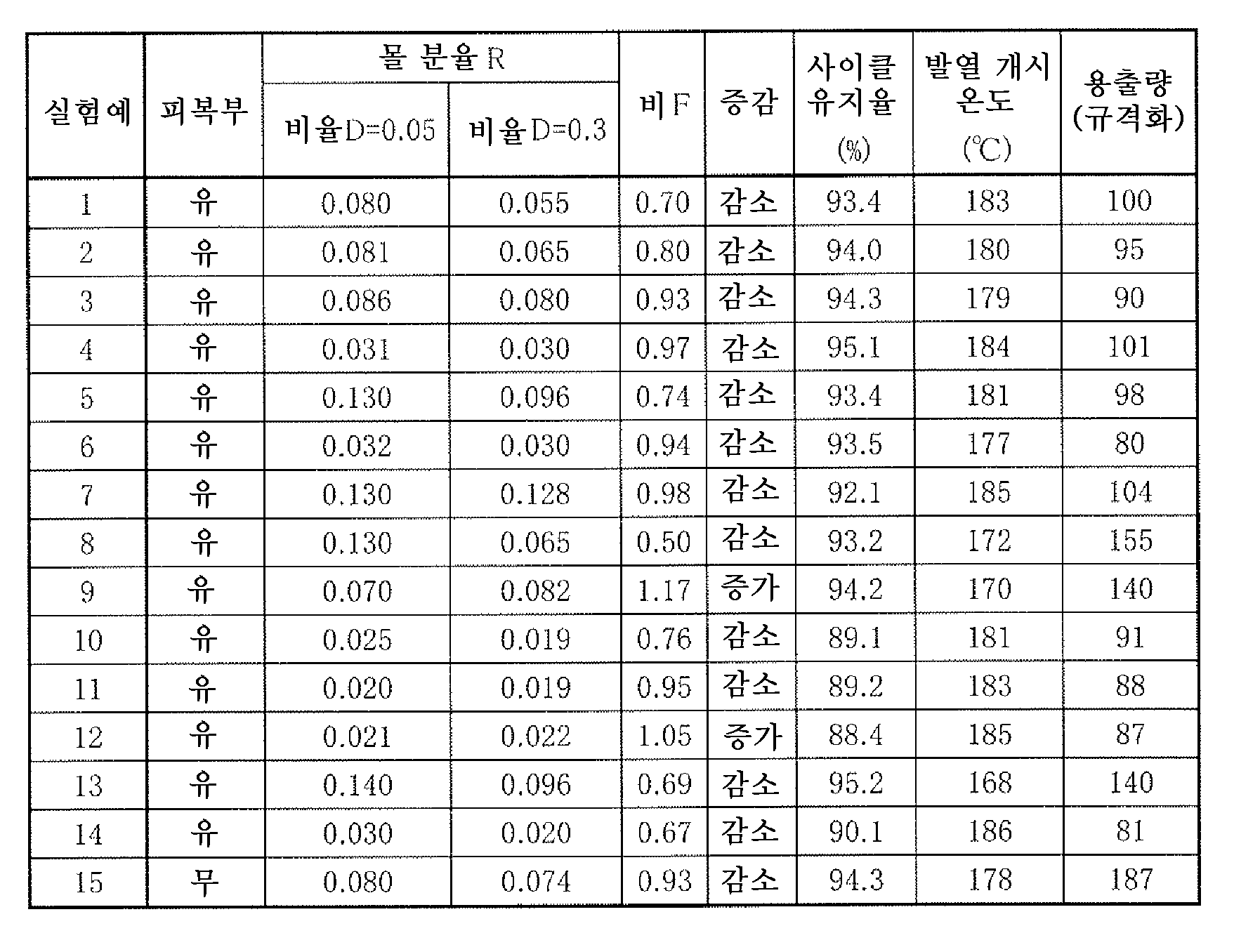
(실험예 15)(Experimental Example 15)
비교를 위해, 피복부를 형성하지 않는 것을 제외하고, 실험예 1 내지 14와 마찬가지의 수순을 거침으로써, 정극 활물질(중심부)을 얻었다. 이 정극 활물질에 관한 몰 분율 R 및 비 F는, 표 2에 나타낸 바와 같다.For comparison, a positive electrode active material (center portion) was obtained by passing through the same procedure as in Experimental Examples 1 to 14, except that no covering portion was formed. The molar fractions R and F of the positive electrode active material are shown in Table 2.
<2. 이차 전지의 제작><2. Production of secondary battery>
(실험예 1 내지 15)(Experimental Examples 1 to 15)
이하의 수순에 의해, 시험용의 이차 전지로서, 도 13에 도시한 코인형의 리튬 이온 이차 전지를 제작하였다.The coin-type lithium ion secondary battery shown in Fig. 13 was produced as a secondary battery for testing by the following procedure.
이 이차 전지에서는, 외장 컵(54)의 내부에 수용된 시험 전극(51)과 외장 캔(52)의 내부에 수용된 대향 전극(53)이 세퍼레이터(55)를 개재하여 적층되어 있음과 함께, 외장 캔(52)과 외장 컵(54)이 가스킷(56)을 개재하여 코오킹되어 있다. 이 세퍼레이터(55)에는, 전해액이 함침되어 있다.In this secondary battery, the
시험 전극(51)을 제작하는 경우에는, 처음에, 상기한 정극 활물질 98질량부와, 정극 결착제(폴리불화비닐리덴) 1.2질량부와, 정극 도전제(케첸 블랙) 0.8질량부를 혼합함으로써, 정극합제로 하였다. 계속해서, 유기 용제(N-메틸-2-피롤리돈)에 정극합제를 분산시킴으로써, 페이스트상의 정극합제 슬러리로 하였다. 계속해서, 코팅 장치를 사용하여 정극 집전체(15㎛ 두께의 알루미늄박)의 양면에 정극합제 슬러리를 도포한 후, 그 정극합제 슬러리를 온풍 건조시킴으로써, 정극 활물질층을 형성하였다. 마지막으로, 유압 프레스기를 사용하여 정극 활물질층을 압축 성형하였다.When manufacturing the
대향 전극(53)을 제작하는 경우에는, 처음에, 부극 활물질(흑연) 95질량부와, 부극 결착제(폴리불화비닐리덴) 5질량부를 혼합함으로써, 부극합제로 하였다. 계속해서, 유기 용제(N-메틸-2-피롤리돈)에 부극합제를 분산시킴으로써, 페이스트상의 부극합제 슬러리로 하였다. 계속해서, 코팅 장치를 사용하여 부극 집전체(12㎛ 두께의 구리박)의 양면에 부극합제 슬러리를 도포한 후, 그 부극합제 슬러리를 온풍 건조시킴으로써, 부극 활물질층을 형성하였다. 마지막으로, 유압 프레스기를 사용하여 부극 활물질층을 압축 성형하였다.When producing the
전해액을 제조하는 경우에는, 용매(탄산에틸렌 및 탄산프로필렌)에 전해질염(육불화인산리튬)을 용해시켰다. 이 경우에는, 용매의 조성을 체적비로 탄산에틸렌 : 탄산프로필렌=1 : 1로 함과 함께, 전해액염의 함유량을 용매에 대하여 1mol/㎤(=1mol/l)로 하였다.When preparing an electrolytic solution, an electrolyte salt (lithium hexafluorophosphate) was dissolved in a solvent (ethylene carbonate and propylene carbonate). In this case, the composition of the solvent was ethylene carbonate:propylene carbonate=1:1 in a volume ratio, and the content of the electrolytic solution salt was 1 mol/cm 3 (=1 mol/l) relative to the solvent.
이차 전지를 조립하는 경우에는, 처음에, 시험 전극(51)을 펠릿상(직경=15㎜)으로 스탬핑한 후, 그 시험 전극(51)을 외장 컵(54)의 내부에 수용하였다. 계속해서, 대향 전극(53)을 펠릿상(직경=16㎜)으로 스탬핑한 후, 그 대향 전극(53)을 외장 캔(52)의 내부에 수용하였다. 계속해서, 전해액이 함침된 세퍼레이터(55)(다공성 폴리올레핀 필름)를 개재하여, 외장 컵(54)에 수용된 시험 전극(51)과 외장 캔(52)에 수용된 대향 전극(53)을 적층시켰다. 마지막으로, 가스킷(56)을 개재하여 외장 캔(52) 및 외장 컵(54)을 코오킹하였다. 이에 의해, 코인형의 이차 전지가 완성되었다.In the case of assembling the secondary battery, first, the
<3. 이차 전지의 평가><3. Evaluation of secondary battery>
이차 전지의 전지 특성으로서 사이클 특성, 안전 특성 및 보존 특성을 조사한바, 표 2에 나타낸 결과가 얻어졌다.When the cycle characteristics, safety characteristics, and storage characteristics were investigated as battery characteristics of the secondary battery, the results shown in Table 2 were obtained.
사이클 특성을 조사하는 경우에는, 처음에, 전지 상태를 안정화시키기 위해, 상온 환경 중(23℃)에서 이차 전지를 1사이클 충방전시켰다. 계속해서, 동일 환경 중에서 이차 전지를 다시 1사이클 충방전시킴으로써, 2사이클째의 방전 용량을 측정하였다. 계속해서, 동일 환경 중에서 사이클수의 합계가 50사이클로 될 때까지 이차 전지를 반복하여 충방전시킴으로써, 50사이클째의 방전 용량을 측정하였다. 마지막으로, 사이클 유지율(%)=(50사이클째의 방전 용량/2사이클째의 방전 용량)×100을 산출하였다.In the case of examining the cycle characteristics, first, in order to stabilize the battery state, the secondary battery was charged and discharged one cycle in a normal temperature environment (23°C). Subsequently, the secondary battery was charged and discharged one cycle again in the same environment to measure the discharge capacity at the second cycle. Subsequently, the discharge capacity at the 50th cycle was measured by repeatedly charging and discharging the secondary battery until the total number of cycles became 50 cycles in the same environment. Finally, the cycle retention rate (%) = (the discharge capacity at the 50th cycle/the discharge capacity at the 2nd cycle) x 100 was calculated.
1사이클째 및 2사이클째의 충방전 조건은 이하와 같다. 충전 시에는, 0.5㎃의 전류로 전압이 4.35V에 도달할 때까지 충전한 후, 또한 4.35V의 전압으로 총 충전 시간이 10시간에 도달할 때까지 충전하였다. 방전 시에는, 2.5㎃의 전류로 전압이 3.0V에 도달할 때까지 방전하였다.Charging and discharging conditions at the first and second cycles are as follows. At the time of charging, it was charged with a current of 0.5 mA until the voltage reached 4.35 V, and then charged with a voltage of 4.35 V until the total charging time reached 10 hours. At the time of discharge, discharge was performed at a current of 2.5 mA until the voltage reached 3.0 V.
3사이클째 이후의 충방전 조건은 이하와 같다. 충전 시에는, 2.5㎃의 전류로 전압이 4.35V에 도달할 때까지 충전한 후, 또한 4.35V의 전압으로 총 충전 시간이 2시간에 도달할 때까지 충전하였다. 방전 시에는, 2.5㎃의 전류로 전압이 3.0V에 도달할 때까지 방전하였다.Charging and discharging conditions after the third cycle are as follows. At the time of charging, the battery was charged with a current of 2.5 mA until the voltage reached 4.35 V, and then charged with a voltage of 4.35 V until the total charging time reached 2 hours. At the time of discharge, discharge was performed at a current of 2.5 mA until the voltage reached 3.0 V.
안전 특성을 조사하는 경우에는, 상기한 전지 상태가 안정화된 이차 전지를 사용하여, 상온 환경 중(23℃)에서 이차 전지를 1사이클 충방전시킨 후, 동일 환경 중에서 이차 전지를 다시 충전시켰다.In the case of investigating safety characteristics, the secondary battery was charged and discharged one cycle in a normal temperature environment (23° C.) using the secondary battery in which the battery state was stabilized, and then the secondary battery was charged again in the same environment.
충전 시에는, 0.5㎃의 전류로 전압이 4.35V에 도달할 때까지 충전한 후, 또한 4.35V의 전압으로 총 충전 시간이 10시간에 도달할 때까지 충전하였다. 방전 시에는, 2.5㎃의 전류로 전압이 3.0V에 도달할 때까지 방전하였다.At the time of charging, it was charged with a current of 0.5 mA until the voltage reached 4.35 V, and then charged with a voltage of 4.35 V until the total charging time reached 10 hours. At the time of discharge, discharge was performed at a current of 2.5 mA until the voltage reached 3.0 V.
계속해서, 충전 상태의 이차 전지를 해체함으로써, 시험 전극(51)을 취출하였다. 계속해서, 유기 용제(탄산디메틸) 중에 시험 전극(51)을 침지(침지 시간=10분간)시킨 후, 진공 환경 중에서 대향 전극(53)을 건조(건조 온도=60℃, 건조 시간=8시간)시켰다. 계속해서, 시험 전극(51)으로부터 정극합제를 추출한 후, 새롭게 제조된 전해액과 함께 정극합제를 SUS 캔에 봉입하였다. 이 전해액의 조성은, 이차 전지를 제작하기 위해 사용된 전해액의 조성과 마찬가지이다. 마지막으로, 시차 주사 열량 측정 장치(세이코 인스트루먼츠 가부시키가이샤제의 EXSTAR6000)를 사용하여 시차 주사 열량을 측정함으로써, 안전 특성(열 안정성)을 평가하기 위한 지표인 제1 발열 피크의 발열 개시 온도(℃)를 특정하였다.Subsequently, the
보존 특성을 조사하는 경우에는, 처음에, 세퍼레이터(55)를 2매 겹침으로 한 것을 제외하고, 실험예 1 내지 15와 마찬가지의 수순에 의해, 보존 시험용의 이차 전지를 제작하였다. 계속해서, 상온 환경 중(23℃)에서 보존 시험용의 이차 전지를 1사이클 충방전시킨 후, 동일 환경 중에서 보존 시험용의 이차 전지를 다시 충전시켰다. 충방전 조건은, 안전 특성을 조사한 경우와 마찬가지로 하였다. 계속해서, 고온 환경 중(60℃)에 있어서 충전 상태의 보존 시험용의 이차 전지를 보존(보존 시간=168시간)하였다.In the case of examining the storage characteristics, a secondary battery for storage testing was produced in the same manner as in Experimental Examples 1 to 15, except that the
계속해서, 보존 후의 이차 전지를 해체함으로써, 대향 전극(53) 및 세퍼레이터(44)를 취출한 후, 1mol/dm3(=1mol/l)의 염산 15㎤(=15ml) 중에 대향 전극(53) 및 세퍼레이터(55)를 투입함으로써, 염산 용액을 얻었다. 계속해서, 염산 용액을 자비(자비 시간=15분간)한 후, 그 염산 용액을 여과하였다. 계속해서, ICP 발광 분광 분석 장치(히타치 하이테크 사이언스 가부시키가이샤제의 SPS3100 시퀀셜형 ICP 발광 분광 분석 장치)를 사용하여, 여과 후의 염산 용액 중에 포함되어 있는 코발트의 농도를 측정하였다.Subsequently, by dismantling the secondary battery after storage, the
마지막으로, 하기의 식 (5)에 기초하여, 보존 시험용의 이차 전지의 보존 시에 있어서의 코발트의 용출량을 산출하였다. 또한, 표 2에 나타낸 용출량은, 실험예 1의 용출량을 100으로 하여 규격화한 값이다.Finally, based on the following formula (5), the amount of elution of cobalt during storage of the secondary battery for storage test was calculated. In addition, the elution amount shown in Table 2 is the value normalized by setting the elution amount of Experimental Example 1 to 100.

<4. 고찰><4. Consideration>
표 2로부터 명백해지는 바와 같이, 사이클 유지율, 발열 개시 온도 및 용출량의 각각은, 정극 활물질의 구성에 따라서 크게 변동되었다.As apparent from Table 2, each of the cycle retention rate, the heat generation start temperature, and the amount of elution varied greatly depending on the configuration of the positive electrode active material.
구체적으로는, 중심부의 표면에 피복부가 형성되어 있지 않은 경우(실험예 15)에는, 사이클 유지율 및 발열 개시 온도에 관해서는 비교적 양호한 결과가 얻어졌지만, 용출량이 현저하게 증가되었다.Specifically, in the case where the coating portion was not formed on the surface of the center portion (Experimental Example 15), relatively good results were obtained with respect to the cycle retention rate and the heat generation start temperature, but the elution amount was significantly increased.
한편, 중심부의 표면에 피복부가 형성되어 있는 경우(실험예 1 내지 14)에는, 비율 D가 D=0.05를 만족시키는 경우의 몰 분율 R이 0.03<R<0.13을 만족시키고, 비율 D가 D=0.3을 만족시키는 경우의 몰 분율 R이 0.01<R<0.13을 만족시키고, 비 F가 0.7≤F≤1을 만족시키고 있으면(실험예 1 내지 7), 그것들의 3개의 조건을 만족시키고 있지 않은 경우(실험예 8 내지 14)와 비교하여, 용출량을 억제하면서, 양호한 사이클 유지율이 얻어짐과 함께 발열 개시 온도가 상승하였다.On the other hand, in the case where the coating portion is formed on the surface of the center portion (Experimental Examples 1 to 14), the molar fraction R when the ratio D satisfies D=0.05 satisfies 0.03<R<0.13, and the ratio D is D= When the molar fraction R when satisfying 0.3 satisfies 0.01<R<0.13, and when the ratio F satisfies 0.7≤F≤1 (Experimental Examples 1 to 7), those three conditions are not satisfied. Compared to (Experimental Examples 8 to 14), while suppressing the elution amount, a good cycle retention rate was obtained and the heating start temperature rose.
이들의 것으로부터, 본 기술의 정극에서는, 정극 활물질의 주요한 구성 원소(코발트, 원소 M, 니켈 및 망간)의 분포(몰 분율 R 및 비율 F)에 관하여 상기한 3개의 조건을 동시에 만족시키고 있다. 이 경우에는, 피복부 중의 주요한 구성 원소(니켈 및 망간)에 의한 중심부의 피복 상태가 적정화됨과 함께, 그 중심부 중의 주요한 구성 원소(원소 M)에 의한 정극 활물질의 결정 구조를 안정화하는 기능이 효과적으로 발휘된다. 이에 의해, 표 1 및 표 2에 나타낸 바와 같이, 사이클 특성, 안전 특성 및 보존 특성이 모두 개선되었다. 따라서, 이차 전지에 있어서 우수한 전지 특성이 얻어졌다.From these, in the positive electrode of the present technology, the above three conditions are simultaneously satisfied with respect to the distribution (molar fraction R and ratio F) of the main constituent elements (cobalt, element M, nickel, and manganese) of the positive electrode active material. In this case, the coating state of the center portion by the main constituent elements (nickel and manganese) in the covering portion is optimized, and the function of stabilizing the crystal structure of the positive electrode active material by the main constituent element (element M) in the center portion is effectively exhibited. do. Thereby, as shown in Table 1 and Table 2, the cycle characteristics, safety characteristics, and storage characteristics were all improved. Therefore, excellent battery characteristics were obtained in the secondary battery.
이상, 일 실시 형태 및 실시예를 들면서 본 기술을 설명하였지만, 본 기술은 일 실시 형태 및 실시예에 있어서 설명한 양태에 한정되지 않고, 다양한 변형이 가능하다.As described above, the present technology has been described with reference to one embodiment and an embodiment, but the present technology is not limited to the embodiments described in one embodiment and the embodiment, and various modifications are possible.
예를 들어, 본 기술의 이차 전지 구성을 설명하기 위해, 전지 구조가 원통형, 라미네이트 필름형 및 코인형임과 함께, 전지 소자가 권회 구조를 갖는 경우를 예로 들었다. 그러나, 본 기술의 이차 전지는, 각형 및 버튼형 등의 다른 전지 구조를 갖는 경우에 적용 가능함과 함께, 전지 소자가 적층 구조 등의 다른 구조를 갖는 경우에도 적용 가능하다.For example, in order to explain the secondary battery configuration of the present technology, the case where the battery structure has a wound structure while the battery structure is cylindrical, laminate film type, and coin type is exemplified. However, the secondary battery of the present technology is applicable to a case where the battery structure has a different structure, such as a square type and a button type, and is also applicable to a case where the battery element has a different structure, such as a stacked structure.
또한, 예를 들어 본 기술의 이차 전지용 정극 활물질 및 이차 전지용 정극은, 이차 전지에 한정되지 않고, 다른 전기 화학 디바이스에 적용되어도 된다. 다른 전기 화학 디바이스는, 예를 들어 캐패시터 등이다.Further, for example, the positive electrode active material for a secondary battery and the positive electrode for a secondary battery of the present technology are not limited to the secondary battery, and may be applied to other electrochemical devices. Other electrochemical devices are, for example, capacitors.
또한, 본 명세서 중에 기재된 효과는 어디까지나 예시이며 한정되는 것은 아니고, 또한, 다른 효과가 있어도 된다.In addition, the effect described in this specification is an illustration to the last, and is not limited, and another effect may be sufficient.
또한, 본 기술은, 이하와 같은 구성을 취하는 것도 가능하다.In addition, the present technology can also take the following structures.
(1)(One)
정극 활물질을 포함하는 정극과, 부극과, 전해액을 구비하고,A positive electrode including a positive electrode active material, a negative electrode, and an electrolytic solution are provided.
상기 정극 활물질은, 코발트(Co) 및 원소 M을 구성 원소로서 포함함과 함께 하기의 식 (1)로 표시되는 리튬 복합 산화물을 포함하는 중심부와, 그 중심부의 표면 중 적어도 일부에 형성됨과 함께 리튬(Li), 니켈(Ni) 및 망간(Mn)을 구성 원소로서 포함하는 피복부를 포함하고,The positive electrode active material includes cobalt (Co) and element M as constituent elements, and is formed on at least a portion of a central portion including a lithium composite oxide represented by the following formula (1), and a surface of the central portion. (Li), nickel (Ni) and manganese (Mn) containing a coating portion containing as a constituent element,
상기 코발트, 상기 원소 M, 상기 니켈 및 상기 망간의 각각은, 상기 정극 활물질의 표면으로부터 중심을 향하는 방향에 있어서 농도가 구배를 갖도록 분포되고,Each of the cobalt, the element M, the nickel and the manganese is distributed such that the concentration has a gradient in a direction from the surface of the positive electrode active material toward the center,
하기의 식 (2)로 표시되는 비율 D(%)에 의해, 상기 정극 활물질의 표면으로부터의 깊이가 규정됨과 함께, 하기의 식 (3)으로 표시되는 몰 분율 R에 의해, 상기 정극 활물질 중에 있어서의 상기 원소 M의 존재량이 규정되고,Depth from the surface of the positive electrode active material is defined by the ratio D (%) represented by the following formula (2), and in the positive electrode active material by the molar fraction R represented by the following formula (3): The abundance of the element M of is defined,
상기 비율 D가 D=0.05를 만족시키는 상기 피복부 내의 위치에 있어서, 상기 몰 분율 R은 0.03<R<0.13을 만족시키고,In the position in the covering where the ratio D satisfies D=0.05, the molar fraction R satisfies 0.03<R<0.13,
상기 비율 D가 D=0.3을 만족시키는 상기 중심부 내의 위치에 있어서, 상기 몰 분율 R은 0.01<R<0.13을 만족시키고,In the position in the center where the ratio D satisfies D=0.3, the molar fraction R satisfies 0.01<R<0.13,
상기 몰 분율 R(D=0.05)에 대한 상기 몰 분율 R(D=0.3)의 비 F는, 0.7≤F≤1을 만족시키는 이차 전지.A secondary battery in which the ratio F of the molar fraction R (D=0.3) to the molar fraction R (D=0.05) satisfies 0.7≦F≦1.
![]()
![]()
(M은 마그네슘(Mg), 알루미늄(Al), 붕소(B), 티타늄(Ti), 바나듐(V), 크롬(Cr), 철(Fe), 구리(Cu), 아연(Zn), 몰리브덴(Mo), 주석(Sn), 텅스텐(W), 지르코늄(Zr), 이트륨(Y), 니오븀(Nb), 칼슘(Ca), 스트론튬(Sr), 비스무트(Bi), 나트륨(Na), 칼륨(K), 규소(Si) 및 인(P) 중 적어도 1종임. x, y 및 z는, 0≤x≤1, 0<y<0.5 및 -0.1≤z≤0.2를 만족시킴)(M is magnesium (Mg), aluminum (Al), boron (B), titanium (Ti), vanadium (V), chromium (Cr), iron (Fe), copper (Cu), zinc (Zn), molybdenum ( Mo), tin (Sn), tungsten (W), zirconium (Zr), yttrium (Y), niobium (Nb), calcium (Ca), strontium (Sr), bismuth (Bi), sodium (Na), potassium ( K), at least one of silicon (Si) and phosphorus (P), where x, y and z satisfy 0≤x≤1, 0<y<0.5 and -0.1≤z≤0.2)


(2)(2)
상기 원소 M은 마그네슘인 상기 (1)에 기재된 이차 전지.The secondary battery according to the above (1), wherein the element M is magnesium.
(3)(3)
상기 리튬 복합 산화물은, 층상 암염형의 결정 구조를 갖는 상기 (1) 또는 (2)에 기재된 이차 전지.The secondary battery according to (1) or (2), wherein the lithium composite oxide has a layered rock salt crystal structure.
(4)(4)
리튬 이온 이차 전지인 상기 (1) 내지 (3) 중 어느 한 항에 기재된 이차 전지.The secondary battery according to any one of (1) to (3) above, which is a lithium ion secondary battery.
(5)(5)
정극 활물질을 포함하고,It contains a positive electrode active material,
상기 정극 활물질은, 코발트 및 원소 M을 구성 원소로서 포함함과 함께 하기의 식 (1)로 표시되는 리튬 복합 산화물을 포함하는 중심부와, 그 중심부의 표면 중 적어도 일부에 형성됨과 함께 리튬, 니켈 및 망간을 구성 원소로서 포함하는 피복부를 포함하고,The positive electrode active material includes cobalt and element M as constituent elements, and is formed on at least a portion of a central portion including a lithium composite oxide represented by the following formula (1) and a surface of the central portion, and lithium, nickel, and It includes a coating part containing manganese as a constituent element,
상기 코발트, 상기 원소 M, 상기 니켈 및 상기 망간의 각각은, 상기 정극 활물질의 표면으로부터 중심을 향하는 방향에 있어서 농도가 구배를 갖도록 분포되고,Each of the cobalt, the element M, the nickel and the manganese is distributed such that the concentration has a gradient in a direction from the surface of the positive electrode active material toward the center,
하기의 식 (2)로 표시되는 비율 D(%)에 의해, 상기 정극 활물질의 표면으로부터의 깊이가 규정됨과 함께, 하기의 식 (3)으로 표시되는 몰 분율 R에 의해, 상기 정극 활물질 중에 있어서의 상기 원소 M의 존재량이 규정되고,Depth from the surface of the positive electrode active material is defined by the ratio D (%) represented by the following formula (2), and in the positive electrode active material by the molar fraction R represented by the following formula (3): The abundance of the element M of is defined,
상기 비율 D가 D=0.05를 만족시키는 상기 피복부 내의 위치에 있어서, 상기 몰 분율 R은 0.03<R<0.13을 만족시키고,In the position in the covering where the ratio D satisfies D=0.05, the molar fraction R satisfies 0.03<R<0.13,
상기 비율 D가 D=0.3을 만족시키는 상기 중심부 내의 위치에 있어서, 상기 몰 분율 R은 0.01<R<0.13을 만족시키고,In the position in the center where the ratio D satisfies D=0.3, the molar fraction R satisfies 0.01<R<0.13,
상기 몰 분율 R(D=0.05)에 대한 상기 몰 분율 R(D=0.3)의 비 F는, 0.7≤F≤1을 만족시키는 이차 전지용 정극.The ratio F of the molar fraction R (D=0.3) to the molar fraction R (D=0.05) satisfies 0.7≦F≦1.
![]()
![]()
(M은 마그네슘, 알루미늄, 붕소, 티타늄, 바나듐, 크롬, 철, 구리, 아연, 몰리브덴, 주석, 텅스텐, 지르코늄, 이트륨, 니오븀, 칼슘, 스트론튬, 비스무트, 나트륨, 칼륨, 규소 및 인 중 적어도 1종임. x, y 및 z는, 0≤x≤1, 0<y<0.5 및 -0.1≤z≤0.2를 만족시킴)(M is at least one of magnesium, aluminum, boron, titanium, vanadium, chromium, iron, copper, zinc, molybdenum, tin, tungsten, zirconium, yttrium, niobium, calcium, strontium, bismuth, sodium, potassium, silicon and phosphorus. .x, y and z satisfy 0≤x≤1, 0<y<0.5 and -0.1≤z≤0.2)


(6)(6)
코발트 및 원소 M을 구성 원소로서 포함함과 함께 하기의 식 (1)로 표시되는 리튬 복합 산화물을 포함하는 중심부와, 그 중심부의 표면 중 적어도 일부에 형성됨과 함께 리튬, 니켈 및 망간을 구성 원소로서 포함하는 피복부를 포함하고,While containing cobalt and element M as constituent elements, a central portion containing the lithium composite oxide represented by the following formula (1), and formed on at least a part of the surface of the central portion, and lithium, nickel and manganese as constituent elements It includes a covering portion,
상기 코발트, 상기 원소 M, 상기 니켈 및 상기 망간의 각각은, 상기 피복부의 표면으로부터 상기 중심부의 중심을 향하는 방향에 있어서 농도가 구배를 갖도록 분포되고,Each of the cobalt, the element M, the nickel, and the manganese is distributed such that the concentration has a gradient in a direction from the surface of the coating portion toward the center of the center portion,
하기의 식 (2)로 표시되는 비율 D(%)에 의해, 상기 피복부의 표면으로부터의 깊이가 규정됨과 함께, 하기의 식 (3)으로 표시되는 몰 분율 R에 의해, 상기 중심부 및 상기 피복부의 각각에 있어서의 상기 원소 M의 존재량이 규정되고,The depth from the surface of the coating portion is defined by the ratio D (%) represented by the following formula (2), and by the molar fraction R represented by the following formula (3), the central portion and the coating portion The abundance of the element M in each is defined,
상기 비율 D가 D=0.05를 만족시키는 상기 피복부 내의 위치에 있어서, 상기 몰 분율 R은 0.03<R<0.13을 만족시키고,In the position in the covering where the ratio D satisfies D=0.05, the molar fraction R satisfies 0.03<R<0.13,
상기 비율 D가 D=0.3을 만족시키는 상기 중심부 내의 위치에 있어서, 상기 몰 분율 R은 0.01<R<0.13을 만족시키고,In the position in the center where the ratio D satisfies D=0.3, the molar fraction R satisfies 0.01<R<0.13,
상기 몰 분율 R(D=0.05)에 대한 상기 몰 분율 R(D=0.3)의 비 F는, 0.7≤F≤1을 만족시키는 이차 전지용 정극 활물질.The ratio F of the molar fraction R (D=0.3) to the molar fraction R (D=0.05) satisfies 0.7≦F≦1, a positive electrode active material for a secondary battery.
![]()
![]()
(M은 마그네슘, 알루미늄, 붕소, 티타늄, 바나듐, 크롬, 철, 구리, 아연, 몰리브덴, 주석, 텅스텐, 지르코늄, 이트륨, 니오븀, 칼슘, 스트론튬, 비스무트, 나트륨, 칼륨, 규소 및 인 중 적어도 1종임. x, y 및 z는, 0≤x≤1, 0<y<0.5 및 -0.1≤z≤0.2를 만족시킴)(M is at least one of magnesium, aluminum, boron, titanium, vanadium, chromium, iron, copper, zinc, molybdenum, tin, tungsten, zirconium, yttrium, niobium, calcium, strontium, bismuth, sodium, potassium, silicon and phosphorus. .x, y and z satisfy 0≤x≤1, 0<y<0.5 and -0.1≤z≤0.2)

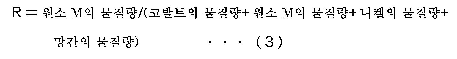
(7)(7)
상기 (1) 내지 (4) 중 어느 한 항에 기재된 이차 전지와, 상기 이차 전지의 동작을 제어하는 제어부와, 상기 제어부의 지시에 따라서 상기 이차 전지의 동작을 전환하는 스위치부를 구비한 전지 팩.A battery pack comprising the secondary battery according to any one of (1) to (4), a control unit for controlling the operation of the secondary battery, and a switch unit for switching the operation of the secondary battery according to the instructions of the control unit.
(8)(8)
상기 (1) 내지 (4) 중 어느 한 항에 기재된 이차 전지와, 상기 이차 전지로부터 공급된 전력을 구동력으로 변환하는 변환부와, 상기 구동력에 따라서 구동하는 구동부와, 상기 이차 전지의 동작을 제어하는 제어부를 구비한 전동 차량.The secondary battery according to any one of (1) to (4), a conversion unit for converting electric power supplied from the secondary battery into driving force, a driving unit for driving according to the driving force, and controlling the operation of the secondary battery Electric vehicle having a control unit.
(9)(9)
상기 (1) 내지 (4) 중 어느 한 항에 기재된 이차 전지와, 상기 이차 전지로부터 전력을 공급받는 1 또는 2 이상의 전기 기기와, 상기 이차 전지로부터의 상기 전기 기기에 대한 전력 공급을 제어하는 제어부를 구비한 전력 저장 시스템.The secondary battery according to any one of (1) to (4), one or two or more electric devices supplied with power from the secondary battery, and a control unit for controlling power supply to the electrical device from the secondary battery Power storage system having a.
(10)(10)
상기 (1) 내지 (4) 중 어느 한 항에 기재된 이차 전지와, 상기 이차 전지로부터 전력을 공급받는 가동부를 구비한 전동 공구.The electric tool provided with the secondary battery in any one of said (1)-(4), and the movable part supplied with electric power from the said secondary battery.
(11)(11)
상기 (1) 내지 (4) 중 어느 한 항에 기재된 이차 전지를 전력 공급원으로서 구비한 전자 기기.An electronic device comprising the secondary battery according to any one of (1) to (4) above as a power source.
본 출원은, 일본 특허청에 있어서 2016년 2월 8일에 출원된 일본 특허 출원 번호 제2016-022013호를 기초로 하여 우선권을 주장하는 것이며, 이 출원의 모든 내용을 참조에 의해 본 출원에 원용한다.This application claims priority based on Japanese Patent Application No. 2016-022013 filed on February 8, 2016 by the Japan Patent Office, and the entire contents of this application are incorporated in this application by reference. .
당업자라면 설계상의 요건이나 다른 요인에 따라서, 다양한 수정, 콤비네이션, 서브 콤비네이션 및 변경을 상도할 수 있지만, 그것들은 첨부의 청구범위의 취지나 그 균등물의 범위에 포함되는 것인 것이 이해된다.Various modifications, combinations, sub-combinations, and changes can be devised by those skilled in the art depending on design requirements or other factors, but it is understood that they are included in the scope of the appended claims or the equivalents thereof.
Claims (8)
상기 정극 활물질은, 코발트(Co) 및 원소 M을 구성 원소로서 포함함과 함께 하기의 식 (1)로 표시되는 리튬 복합 산화물을 포함하는 중심부와, 그 중심부의 표면 중 적어도 일부에 형성됨과 함께 리튬(Li), 니켈(Ni) 및 망간(Mn)을 구성 원소로서 포함하는 피복부를 포함하고,
상기 코발트, 상기 원소 M, 상기 니켈 및 상기 망간의 각각은, 상기 정극 활물질의 표면으로부터 중심을 향하는 방향에 있어서 농도가 구배를 갖도록 분포되고,
하기의 식 (2)로 표시되는 비율 D(%)에 의해, 상기 정극 활물질의 표면으로부터의 깊이가 규정됨과 함께, 하기의 식 (3)으로 표시되는 몰 분율 R에 의해, 상기 정극 활물질 중에 있어서의 상기 원소 M의 존재량이 규정되고,
상기 비율 D가 D=0.05를 만족시키는 상기 피복부 내의 위치에 있어서, 상기 몰 분율 R은 0.03<R<0.13을 만족시키고,
상기 비율 D가 D=0.3을 만족시키는 상기 중심부 내의 위치에 있어서, 상기 몰 분율 R은 0.01<R<0.13을 만족시키고,
상기 몰 분율 R(D=0.05)에 대한 상기 몰 분율 R(D=0.3)의 비 F는, 0.7≤F≤1을 만족시키고,
상기 원소 M은 마그네슘이고,
상기 리튬 복합 산화물은, 층상 암염형의 결정 구조를 갖는 리튬 이온 이차 전지.
(x, y 및 z는, 0≤x≤1, 0<y<0.5 및 -0.1≤z≤0.2를 만족시킴)


The positive electrode active material includes cobalt (Co) and element M as constituent elements, and is formed on at least a portion of a central portion including a lithium composite oxide represented by the following formula (1), and a surface of the central portion. (Li), nickel (Ni) and manganese (Mn) containing a coating portion containing as a constituent element,
Each of the cobalt, the element M, the nickel and the manganese is distributed such that the concentration has a gradient in a direction from the surface of the positive electrode active material toward the center,
Depth from the surface of the positive electrode active material is defined by the ratio D (%) represented by the following formula (2), and in the positive electrode active material by the molar fraction R represented by the following formula (3): The abundance of the element M of is defined,
In the position in the covering where the ratio D satisfies D=0.05, the molar fraction R satisfies 0.03<R<0.13,
In the position in the center where the ratio D satisfies D=0.3, the molar fraction R satisfies 0.01<R<0.13,
The ratio F of the molar fraction R (D=0.3) to the molar fraction R (D=0.05) satisfies 0.7≦F≦1,
The element M is magnesium,
The lithium composite oxide is a lithium ion secondary battery having a layered rock salt crystal structure.
(x, y and z satisfy 0≤x≤1, 0<y<0.5 and -0.1≤z≤0.2)
상기 정극 활물질은, 코발트 및 원소 M을 구성 원소로서 포함함과 함께 하기의 식 (1)로 표시되는 리튬 복합 산화물을 포함하는 중심부와, 그 중심부의 표면 중 적어도 일부에 형성됨과 함께 리튬, 니켈 및 망간을 구성 원소로서 포함하는 피복부를 포함하고,
상기 코발트, 상기 원소 M, 상기 니켈 및 상기 망간의 각각은, 상기 정극 활물질의 표면으로부터 중심을 향하는 방향에 있어서 농도가 구배를 갖도록 분포되고,
하기의 식 (2)로 표시되는 비율 D(%)에 의해, 상기 정극 활물질의 표면으로부터의 깊이가 규정됨과 함께, 하기의 식 (3)으로 표시되는 몰 분율 R에 의해, 상기 정극 활물질 중에 있어서의 상기 원소 M의 존재량이 규정되고,
상기 비율 D가 D=0.05를 만족시키는 상기 피복부 내의 위치에 있어서, 상기 몰 분율 R은 0.03<R<0.13을 만족시키고,
상기 비율 D가 D=0.3을 만족시키는 상기 중심부 내의 위치에 있어서, 상기 몰 분율 R은 0.01<R<0.13을 만족시키고,
상기 몰 분율 R(D=0.05)에 대한 상기 몰 분율 R(D=0.3)의 비 F는, 0.7≤F≤1을 만족시키고,
상기 원소 M은 마그네슘이고,
상기 리튬 복합 산화물은, 층상 암염형의 결정 구조를 갖는 리튬 이온 이차 전지용 정극.
(x, y 및 z는, 0≤x≤1, 0<y<0.5 및 -0.1≤z≤0.2를 만족시킴)


The positive electrode active material includes cobalt and element M as constituent elements, and is formed on at least a portion of a central portion including a lithium composite oxide represented by the following formula (1) and a surface of the central portion, and lithium, nickel, and It includes a coating part containing manganese as a constituent element,
Each of the cobalt, the element M, the nickel and the manganese is distributed such that the concentration has a gradient in a direction from the surface of the positive electrode active material toward the center,
Depth from the surface of the positive electrode active material is defined by the ratio D (%) represented by the following formula (2), and in the positive electrode active material by the molar fraction R represented by the following formula (3): The abundance of the element M of is defined,
In the position in the covering where the ratio D satisfies D=0.05, the molar fraction R satisfies 0.03<R<0.13,
In the position in the center where the ratio D satisfies D=0.3, the molar fraction R satisfies 0.01<R<0.13,
The ratio F of the molar fraction R (D=0.3) to the molar fraction R (D=0.05) satisfies 0.7≦F≦1,
The element M is magnesium,
The lithium composite oxide is a positive electrode for a lithium ion secondary battery having a layered rock salt crystal structure.
(x, y and z satisfy 0≤x≤1, 0<y<0.5 and -0.1≤z≤0.2)
상기 코발트, 상기 원소 M, 상기 니켈 및 상기 망간의 각각은, 상기 피복부의 표면으로부터 상기 중심부의 중심을 향하는 방향에 있어서 농도가 구배를 갖도록 분포되고,
하기의 식 (2)로 표시되는 비율 D(%)에 의해, 상기 피복부의 표면으로부터의 깊이가 규정됨과 함께, 하기의 식 (3)으로 표시되는 몰 분율 R에 의해, 상기 중심부 및 상기 피복부의 각각에 있어서의 상기 원소 M의 존재량이 규정되고,
상기 비율 D가 D=0.05를 만족시키는 상기 피복부 내의 위치에 있어서, 상기 몰 분율 R은 0.03<R<0.13을 만족시키고,
상기 비율 D가 D=0.3을 만족시키는 상기 중심부 내의 위치에 있어서, 상기 몰 분율 R은 0.01<R<0.13을 만족시키고,
상기 몰 분율 R(D=0.05)에 대한 상기 몰 분율 R(D=0.3)의 비 F는, 0.7≤F≤1을 만족시키고,
상기 원소 M은 마그네슘이고,
상기 리튬 복합 산화물은, 층상 암염형의 결정 구조를 갖는 리튬 이온 이차 전지용 정극 활물질.
(x, y 및 z는, 0≤x≤1, 0<y<0.5 및 -0.1≤z≤0.2를 만족시킴)


Each of the cobalt, the element M, the nickel, and the manganese is distributed such that the concentration has a gradient in a direction from the surface of the coating portion toward the center of the center portion,
The depth from the surface of the coating portion is defined by the ratio D (%) represented by the following formula (2), and by the molar fraction R represented by the following formula (3), the central portion and the coating portion The abundance of the element M in each is defined,
In the position in the covering where the ratio D satisfies D=0.05, the molar fraction R satisfies 0.03<R<0.13,
In the position in the center where the ratio D satisfies D=0.3, the molar fraction R satisfies 0.01<R<0.13,
The ratio F of the molar fraction R (D=0.3) to the molar fraction R (D=0.05) satisfies 0.7≦F≦1,
The element M is magnesium,
The lithium composite oxide is a positive electrode active material for a lithium ion secondary battery having a layered rock salt crystal structure.
(x, y and z satisfy 0≤x≤1, 0<y<0.5 and -0.1≤z≤0.2)
상기 리튬 이온 이차 전지는, 정극 활물질을 포함하는 정극과, 부극과, 비수 전해액을 구비하고,
상기 정극 활물질은, 코발트 및 원소 M을 구성 원소로서 포함함과 함께 하기의 식 (1)로 표시되는 리튬 복합 산화물을 포함하는 중심부와, 그 중심부의 표면 중 적어도 일부에 형성됨과 함께 리튬, 니켈 및 망간을 구성 원소로서 포함하는 피복부를 포함하고,
상기 코발트, 상기 원소 M, 상기 니켈 및 상기 망간의 각각은, 상기 정극 활물질의 표면으로부터 중심을 향하는 방향에 있어서 농도가 구배를 갖도록 분포되고,
하기의 식 (2)로 표시되는 비율 D(%)에 의해, 상기 정극 활물질의 표면으로부터의 깊이가 규정됨과 함께, 하기의 식 (3)으로 표시되는 몰 분율 R에 의해, 상기 정극 활물질 중에 있어서의 상기 원소 M의 존재량이 규정되고,
상기 비율 D가 D=0.05를 만족시키는 상기 피복부 내의 위치에 있어서, 상기 몰 분율 R은 0.03<R<0.13을 만족시키고,
상기 비율 D가 D=0.3을 만족시키는 상기 중심부 내의 위치에 있어서, 상기 몰 분율 R은 0.01<R<0.13을 만족시키고,
상기 몰 분율 R(D=0.05)에 대한 상기 몰 분율 R(D=0.3)의 비 F는, 0.7≤F≤1을 만족시키고,
상기 원소 M은 마그네슘이고,
상기 리튬 복합 산화물은, 층상 암염형의 결정 구조를 갖는 전지 팩.
(x, y 및 z는, 0≤x≤1, 0<y<0.5 및 -0.1≤z≤0.2를 만족시킴)


The lithium ion secondary battery includes a positive electrode, a negative electrode, and a non-aqueous electrolyte containing a positive electrode active material,
The positive electrode active material includes cobalt and element M as constituent elements, and is formed on at least a portion of a central portion including a lithium composite oxide represented by the following formula (1) and a surface of the central portion, and lithium, nickel, and It includes a coating part containing manganese as a constituent element,
Each of the cobalt, the element M, the nickel and the manganese is distributed such that the concentration has a gradient in a direction from the surface of the positive electrode active material toward the center,
Depth from the surface of the positive electrode active material is defined by the ratio D (%) represented by the following formula (2), and in the positive electrode active material by the molar fraction R represented by the following formula (3): The abundance of the element M of is defined,
In the position in the covering where the ratio D satisfies D=0.05, the molar fraction R satisfies 0.03<R<0.13,
In the position in the center where the ratio D satisfies D=0.3, the molar fraction R satisfies 0.01<R<0.13,
The ratio F of the molar fraction R (D=0.3) to the molar fraction R (D=0.05) satisfies 0.7≦F≦1,
The element M is magnesium,
The lithium composite oxide is a battery pack having a layered rock salt crystal structure.
(x, y and z satisfy 0≤x≤1, 0<y<0.5 and -0.1≤z≤0.2)
상기 리튬 이온 이차 전지는, 정극 활물질을 포함하는 정극과, 부극과, 비수 전해액을 구비하고,
상기 정극 활물질은, 코발트 및 원소 M을 구성 원소로서 포함함과 함께 하기의 식 (1)로 표시되는 리튬 복합 산화물을 포함하는 중심부와, 그 중심부의 표면 중 적어도 일부에 형성됨과 함께 리튬, 니켈 및 망간을 구성 원소로서 포함하는 피복부를 포함하고,
상기 코발트, 상기 원소 M, 상기 니켈 및 상기 망간의 각각은, 상기 정극 활물질의 표면으로부터 중심을 향하는 방향에 있어서 농도가 구배를 갖도록 분포되고,
하기의 식 (2)로 표시되는 비율 D(%)에 의해, 상기 정극 활물질의 표면으로부터의 깊이가 규정됨과 함께, 하기의 식 (3)으로 표시되는 몰 분율 R에 의해, 상기 정극 활물질 중에 있어서의 상기 원소 M의 존재량이 규정되고,
상기 비율 D가 D=0.05를 만족시키는 상기 피복부 내의 위치에 있어서, 상기 몰 분율 R은 0.03<R<0.13을 만족시키고,
상기 비율 D가 D=0.3을 만족시키는 상기 중심부 내의 위치에 있어서, 상기 몰 분율 R은 0.01<R<0.13을 만족시키고,
상기 몰 분율 R(D=0.05)에 대한 상기 몰 분율 R(D=0.3)의 비 F는, 0.7≤F≤1을 만족시키고,
상기 원소 M은 마그네슘이고,
상기 리튬 복합 산화물은, 층상 암염형의 결정 구조를 갖는 전동 차량.
(x, y 및 z는, 0≤x≤1, 0<y<0.5 및 -0.1≤z≤0.2를 만족시킴)


The lithium ion secondary battery includes a positive electrode, a negative electrode, and a non-aqueous electrolyte containing a positive electrode active material,
The positive electrode active material includes cobalt and element M as constituent elements, and is formed on at least a portion of a central portion including a lithium composite oxide represented by the following formula (1) and a surface of the central portion, and lithium, nickel, and It includes a coating part containing manganese as a constituent element,
Each of the cobalt, the element M, the nickel and the manganese is distributed such that the concentration has a gradient in a direction from the surface of the positive electrode active material toward the center,
Depth from the surface of the positive electrode active material is defined by the ratio D (%) represented by the following formula (2), and in the positive electrode active material by the molar fraction R represented by the following formula (3): The abundance of the element M of is defined,
In the position in the covering where the ratio D satisfies D=0.05, the molar fraction R satisfies 0.03<R<0.13,
In the position in the center where the ratio D satisfies D=0.3, the molar fraction R satisfies 0.01<R<0.13,
The ratio F of the molar fraction R (D=0.3) to the molar fraction R (D=0.05) satisfies 0.7≦F≦1,
The element M is magnesium,
The lithium composite oxide is an electric vehicle having a layered rock salt crystal structure.
(x, y and z satisfy 0≤x≤1, 0<y<0.5 and -0.1≤z≤0.2)
상기 리튬 이온 이차 전지는, 정극 활물질을 포함하는 정극과, 부극과, 비수 전해액을 구비하고,
상기 정극 활물질은, 코발트 및 원소 M을 구성 원소로서 포함함과 함께 하기의 식 (1)로 표시되는 리튬 복합 산화물을 포함하는 중심부와, 그 중심부의 표면 중 적어도 일부에 형성됨과 함께 리튬, 니켈 및 망간을 구성 원소로서 포함하는 피복부를 포함하고,
상기 코발트, 상기 원소 M, 상기 니켈 및 상기 망간의 각각은, 상기 정극 활물질의 표면으로부터 중심을 향하는 방향에 있어서 농도가 구배를 갖도록 분포되고,
하기의 식 (2)로 표시되는 비율 D(%)에 의해, 상기 정극 활물질의 표면으로부터의 깊이가 규정됨과 함께, 하기의 식 (3)으로 표시되는 몰 분율 R에 의해, 상기 정극 활물질 중에 있어서의 상기 원소 M의 존재량이 규정되고,
상기 비율 D가 D=0.05를 만족시키는 상기 피복부 내의 위치에 있어서, 상기 몰 분율 R은 0.03<R<0.13을 만족시키고,
상기 비율 D가 D=0.3을 만족시키는 상기 중심부 내의 위치에 있어서, 상기 몰 분율 R은 0.01<R<0.13을 만족시키고,
상기 몰 분율 R(D=0.05)에 대한 상기 몰 분율 R(D=0.3)의 비 F는, 0.7≤F≤1을 만족시키고,
상기 원소 M은 마그네슘이고,
상기 리튬 복합 산화물은, 층상 암염형의 결정 구조를 갖는 전력 저장 시스템.
(x, y 및 z는, 0≤x≤1, 0<y<0.5 및 -0.1≤z≤0.2를 만족시킴)
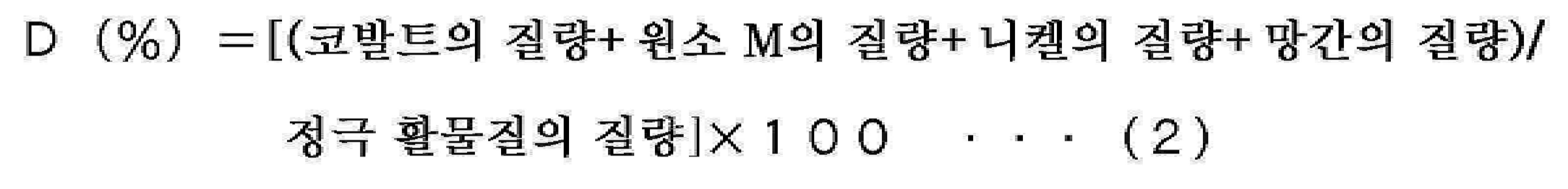

The lithium ion secondary battery includes a positive electrode, a negative electrode, and a non-aqueous electrolyte containing a positive electrode active material,
The positive electrode active material includes cobalt and element M as constituent elements, and is formed on at least a portion of a central portion including a lithium composite oxide represented by the following formula (1) and a surface of the central portion, and lithium, nickel, and It includes a coating part containing manganese as a constituent element,
Each of the cobalt, the element M, the nickel and the manganese is distributed such that the concentration has a gradient in a direction from the surface of the positive electrode active material toward the center,
Depth from the surface of the positive electrode active material is defined by the ratio D (%) represented by the following formula (2), and in the positive electrode active material by the molar fraction R represented by the following formula (3): The abundance of the element M of is defined,
In the position in the covering where the ratio D satisfies D=0.05, the molar fraction R satisfies 0.03<R<0.13,
In the position in the center where the ratio D satisfies D=0.3, the molar fraction R satisfies 0.01<R<0.13,
The ratio F of the molar fraction R (D=0.3) to the molar fraction R (D=0.05) satisfies 0.7≦F≦1,
The element M is magnesium,
The lithium composite oxide, a power storage system having a layered rock salt crystal structure.
(x, y and z satisfy 0≤x≤1, 0<y<0.5 and -0.1≤z≤0.2)
상기 리튬 이온 이차 전지는, 정극 활물질을 포함하는 정극과, 부극과, 비수 전해액을 구비하고,
상기 정극 활물질은, 코발트 및 원소 M을 구성 원소로서 포함함과 함께 하기의 식 (1)로 표시되는 리튬 복합 산화물을 포함하는 중심부와, 그 중심부의 표면 중 적어도 일부에 형성됨과 함께 리튬, 니켈 및 망간을 구성 원소로서 포함하는 피복부를 포함하고,
상기 코발트, 상기 원소 M, 상기 니켈 및 상기 망간의 각각은, 상기 정극 활물질의 표면으로부터 중심을 향하는 방향에 있어서 농도가 구배를 갖도록 분포되고,
하기의 식 (2)로 표시되는 비율 D(%)에 의해, 상기 정극 활물질의 표면으로부터의 깊이가 규정됨과 함께, 하기의 식 (3)으로 표시되는 몰 분율 R에 의해, 상기 정극 활물질 중에 있어서의 상기 원소 M의 존재량이 규정되고,
상기 비율 D가 D=0.05를 만족시키는 상기 피복부 내의 위치에 있어서, 상기 몰 분율 R은 0.03<R<0.13을 만족시키고,
상기 비율 D가 D=0.3을 만족시키는 상기 중심부 내의 위치에 있어서, 상기 몰 분율 R은 0.01<R<0.13을 만족시키고,
상기 몰 분율 R(D=0.05)에 대한 상기 몰 분율 R(D=0.3)의 비 F는, 0.7≤F≤1을 만족시키고,
상기 원소 M은 마그네슘이고,
상기 리튬 복합 산화물은, 층상 암염형의 결정 구조를 갖는 전동 공구.
(x, y 및 z는, 0≤x≤1, 0<y<0.5 및 -0.1≤z≤0.2를 만족시킴)


The lithium ion secondary battery includes a positive electrode, a negative electrode, and a non-aqueous electrolyte containing a positive electrode active material,
The positive electrode active material includes cobalt and element M as constituent elements, and is formed on at least a portion of a central portion including a lithium composite oxide represented by the following formula (1) and a surface of the central portion, and lithium, nickel, and It includes a coating part containing manganese as a constituent element,
Each of the cobalt, the element M, the nickel and the manganese is distributed such that the concentration has a gradient in a direction from the surface of the positive electrode active material toward the center,
Depth from the surface of the positive electrode active material is defined by the ratio D (%) represented by the following formula (2), and in the positive electrode active material by the molar fraction R represented by the following formula (3): The abundance of the element M of is defined,
In the position in the covering where the ratio D satisfies D=0.05, the molar fraction R satisfies 0.03<R<0.13,
In the position in the center where the ratio D satisfies D=0.3, the molar fraction R satisfies 0.01<R<0.13,
The ratio F of the molar fraction R (D=0.3) to the molar fraction R (D=0.05) satisfies 0.7≦F≦1,
The element M is magnesium,
The lithium composite oxide is a power tool having a layered rock salt crystal structure.
(x, y and z satisfy 0≤x≤1, 0<y<0.5 and -0.1≤z≤0.2)
상기 리튬 이온 이차 전지는, 정극 활물질을 포함하는 정극과, 부극과, 비수 전해액을 구비하고,
상기 정극 활물질은, 코발트 및 원소 M을 구성 원소로서 포함함과 함께 하기의 식 (1)로 표시되는 리튬 복합 산화물을 포함하는 중심부와, 그 중심부의 표면 중 적어도 일부에 형성됨과 함께 리튬, 니켈 및 망간을 구성 원소로서 포함하는 피복부를 포함하고,
상기 코발트, 상기 원소 M, 상기 니켈 및 상기 망간의 각각은, 상기 정극 활물질의 표면으로부터 중심을 향하는 방향에 있어서 농도가 구배를 갖도록 분포되고,
하기의 식 (2)로 표시되는 비율 D(%)에 의해, 상기 정극 활물질의 표면으로부터의 깊이가 규정됨과 함께, 하기의 식 (3)으로 표시되는 몰 분율 R에 의해, 상기 정극 활물질 중에 있어서의 상기 원소 M의 존재량이 규정되고,
상기 비율 D가 D=0.05를 만족시키는 상기 피복부 내의 위치에 있어서, 상기 몰 분율 R은 0.03<R<0.13을 만족시키고,
상기 비율 D가 D=0.3을 만족시키는 상기 중심부 내의 위치에 있어서, 상기 몰 분율 R은 0.01<R<0.13을 만족시키고,
상기 몰 분율 R(D=0.05)에 대한 상기 몰 분율 R(D=0.3)의 비 F는, 0.7≤F≤1을 만족시키고,
상기 원소 M은 마그네슘이고,
상기 리튬 복합 산화물은, 층상 암염형의 결정 구조를 갖는 전자 기기.
(x, y 및 z는, 0≤x≤1, 0<y<0.5 및 -0.1≤z≤0.2를 만족시킴)


The lithium ion secondary battery includes a positive electrode, a negative electrode, and a non-aqueous electrolyte containing a positive electrode active material,
The positive electrode active material includes cobalt and element M as constituent elements, and is formed on at least a portion of a central portion including a lithium composite oxide represented by the following formula (1) and a surface of the central portion, and lithium, nickel, and It includes a coating part containing manganese as a constituent element,
Each of the cobalt, the element M, the nickel and the manganese is distributed such that the concentration has a gradient in a direction from the surface of the positive electrode active material toward the center,
Depth from the surface of the positive electrode active material is defined by the ratio D (%) represented by the following formula (2), and in the positive electrode active material by the molar fraction R represented by the following formula (3): The abundance of the element M of is defined,
In the position in the covering where the ratio D satisfies D=0.05, the molar fraction R satisfies 0.03<R<0.13,
In the position in the center where the ratio D satisfies D=0.3, the molar fraction R satisfies 0.01<R<0.13,
The ratio F of the molar fraction R (D=0.3) to the molar fraction R (D=0.05) satisfies 0.7≦F≦1,
The element M is magnesium,
The lithium composite oxide is an electronic device having a layered rock salt crystal structure.
(x, y and z satisfy 0≤x≤1, 0<y<0.5 and -0.1≤z≤0.2)
Applications Claiming Priority (3)
| Application Number | Priority Date | Filing Date | Title |
|---|---|---|---|
| JPJP-P-2016-022013 | 2016-02-08 | ||
| JP2016022013 | 2016-02-08 | ||
| PCT/JP2017/001393 WO2017138309A1 (en) | 2016-02-08 | 2017-01-17 | Secondary battery positive electrode active material, secondary battery positive electrode, secondary battery, battery pack, electric vehicle, electric power storage system, electric tool, and electronic apparatus |
Related Parent Applications (1)
| Application Number | Title | Priority Date | Filing Date |
|---|---|---|---|
| KR1020187022501A Division KR102334080B1 (en) | 2016-02-08 | 2017-01-17 | Positive electrode active material for secondary battery, positive electrode for secondary battery, secondary battery, battery pack, electric vehicle, electric power storage system, power tool and electronic device |
Publications (1)
| Publication Number | Publication Date |
|---|---|
| KR20200091960A true KR20200091960A (en) | 2020-07-31 |
Family
ID=59563725
Family Applications (2)
| Application Number | Title | Priority Date | Filing Date |
|---|---|---|---|
| KR1020207021613A KR20200091960A (en) | 2016-02-08 | 2017-01-17 | Secondary battery positive electrode active material, secondary battery positive electrode, secondary battery, battery pack, electric vehicle, electric power storage system, electric tool, and electronic apparatus |
| KR1020187022501A KR102334080B1 (en) | 2016-02-08 | 2017-01-17 | Positive electrode active material for secondary battery, positive electrode for secondary battery, secondary battery, battery pack, electric vehicle, electric power storage system, power tool and electronic device |
Family Applications After (1)
| Application Number | Title | Priority Date | Filing Date |
|---|---|---|---|
| KR1020187022501A KR102334080B1 (en) | 2016-02-08 | 2017-01-17 | Positive electrode active material for secondary battery, positive electrode for secondary battery, secondary battery, battery pack, electric vehicle, electric power storage system, power tool and electronic device |
Country Status (6)
| Country | Link |
|---|---|
| US (1) | US10522832B2 (en) |
| EP (1) | EP3416218B1 (en) |
| JP (1) | JP6809487B2 (en) |
| KR (2) | KR20200091960A (en) |
| CN (1) | CN108475784B (en) |
| WO (1) | WO2017138309A1 (en) |
Cited By (1)
| Publication number | Priority date | Publication date | Assignee | Title |
|---|---|---|---|---|
| WO2022203401A1 (en) * | 2021-03-23 | 2022-09-29 | 주식회사 엘지화학 | Positive electrode active material for lithium secondary battery, manufacturing method therefor, positive electrode for lithium secondary battery, comprising same, and lithium secondary battery |
Families Citing this family (10)
| Publication number | Priority date | Publication date | Assignee | Title |
|---|---|---|---|---|
| JP6426820B1 (en) * | 2017-11-30 | 2018-11-21 | 住友化学株式会社 | Lithium-containing transition metal composite oxide, positive electrode active material for lithium secondary battery, positive electrode for lithium secondary battery, lithium secondary battery, and method for producing lithium-containing transition metal composite oxide |
| WO2019187131A1 (en) | 2018-03-30 | 2019-10-03 | 株式会社 東芝 | Electrode group, battery, and battery pack |
| FR3079664B1 (en) * | 2018-03-30 | 2020-04-24 | Institut Vedecom | MODULAR POWER SWITCHING ELEMENT AND DEMOUNTABLE ASSEMBLY OF SEVERAL MODULAR ELEMENTS |
| CN110729458B (en) * | 2018-07-17 | 2021-10-01 | 宁德时代新能源科技股份有限公司 | Positive active material, preparation method thereof, positive pole piece and lithium ion secondary battery |
| WO2021153044A1 (en) * | 2020-01-31 | 2021-08-05 | 株式会社村田製作所 | Secondary-battery positive electrode active material, secondary-battery positive electrode, and secondary battery |
| CN113839080B (en) * | 2020-06-24 | 2023-07-14 | 比亚迪股份有限公司 | Lithium ion battery and preparation method thereof |
| KR102542483B1 (en) * | 2020-12-31 | 2023-06-12 | 국민대학교산학협력단 | Ultra-thin LED element, ink for ink-jet and light source comprising the same |
| CN112909320A (en) * | 2020-12-31 | 2021-06-04 | 天津中电新能源研究院有限公司 | High-energy-density lithium ion power battery |
| KR102573265B1 (en) * | 2021-03-25 | 2023-08-31 | 국민대학교산학협력단 | Ultra-thin LED electrode assembly and method for manufacturing thereof |
| CN116247162B (en) * | 2023-05-09 | 2023-08-04 | 宁德时代新能源科技股份有限公司 | Positive pole piece, battery and electric equipment |
Citations (4)
| Publication number | Priority date | Publication date | Assignee | Title |
|---|---|---|---|---|
| JP2002203553A (en) | 2000-12-28 | 2002-07-19 | Sony Corp | Positive-electrode active material and non-aqueous electrolyte secondary battery |
| JP2006331940A (en) | 2005-05-27 | 2006-12-07 | Sony Corp | Positive electrode active material and its manufacturing method as well as positive electrode and battery |
| JP2011129498A (en) | 2009-11-18 | 2011-06-30 | Sony Corp | Positive electrode active material and nonaqueous electrolyte secondary battery |
| JP2014038828A (en) | 2012-08-14 | 2014-02-27 | Samsung Sdi Co Ltd | Positive electrode active material for lithium secondary battery, method for manufacturing positive electrode active material for lithium secondary battery, and lithium secondary battery including positive electrode active material |
Family Cites Families (14)
| Publication number | Priority date | Publication date | Assignee | Title |
|---|---|---|---|---|
| JP5206914B2 (en) * | 2005-05-27 | 2013-06-12 | ソニー株式会社 | Positive electrode active material for lithium ion secondary battery, positive electrode for lithium ion secondary battery, and lithium ion secondary battery |
| JP5034366B2 (en) * | 2006-08-09 | 2012-09-26 | ソニー株式会社 | Positive electrode active material for non-aqueous electrolyte secondary battery, method for producing the same, and non-aqueous electrolyte secondary battery |
| JP2008159560A (en) * | 2006-11-28 | 2008-07-10 | Sony Corp | Method of manufacturing positive electrode active material |
| JP4311438B2 (en) * | 2006-11-28 | 2009-08-12 | ソニー株式会社 | Positive electrode active material, nonaqueous electrolyte secondary battery using the same, and method for producing positive electrode active material |
| WO2008092568A1 (en) * | 2007-01-29 | 2008-08-07 | Umicore | Island-covered lithium cobaltite oxides |
| WO2014178624A1 (en) * | 2013-04-29 | 2014-11-06 | 한양대학교 산학협력단 | Anode active material for lithium rechargeable battery |
| WO2013002457A1 (en) * | 2011-06-27 | 2013-01-03 | 주식회사 에코프로 | Positive electrode active material, electrode including the positive electrode active material, and lithium electrochemical battery |
| CN102623694A (en) * | 2012-03-19 | 2012-08-01 | 宁德新能源科技有限公司 | High-voltage lithium ion battery and cathode material thereof |
| US20150044513A1 (en) * | 2012-03-26 | 2015-02-12 | Sony Corporation | Cathode active material, cathode, secondary battery, battery pack, electric vehicle, electric power storage system, electric power tool, and electronic apparatus |
| KR20130138073A (en) * | 2012-06-08 | 2013-12-18 | 한양대학교 산학협력단 | Precursor for cathod active material of lithium secondary battery, cathode active materials made by the same, and lithium secondary battery containing the same |
| KR101567039B1 (en) * | 2012-12-13 | 2015-11-10 | 주식회사 에코프로 | Manufacuring method of cathode active material for lithium rechargeable battery, and cathode active material made by the same |
| WO2014104759A1 (en) * | 2012-12-26 | 2014-07-03 | 한양대학교 산학협력단 | Cathode active material for lithium secondary batteries |
| KR101568263B1 (en) * | 2014-08-07 | 2015-11-11 | 주식회사 에코프로 | Cathod active material for lithium rechargeable battery and lithium rechargeable battery comprising the same |
| KR101555594B1 (en) * | 2014-10-02 | 2015-10-06 | 주식회사 에코프로 | Cathod active material for lithium rechargeable battery and lithium rechargeable battery comprising the same |
-
2017
- 2017-01-17 CN CN201780007400.7A patent/CN108475784B/en active Active
- 2017-01-17 JP JP2017566561A patent/JP6809487B2/en active Active
- 2017-01-17 KR KR1020207021613A patent/KR20200091960A/en active Application Filing
- 2017-01-17 KR KR1020187022501A patent/KR102334080B1/en active IP Right Grant
- 2017-01-17 EP EP17750034.5A patent/EP3416218B1/en active Active
- 2017-01-17 WO PCT/JP2017/001393 patent/WO2017138309A1/en active Application Filing
-
2018
- 2018-07-23 US US16/041,911 patent/US10522832B2/en active Active
Patent Citations (4)
| Publication number | Priority date | Publication date | Assignee | Title |
|---|---|---|---|---|
| JP2002203553A (en) | 2000-12-28 | 2002-07-19 | Sony Corp | Positive-electrode active material and non-aqueous electrolyte secondary battery |
| JP2006331940A (en) | 2005-05-27 | 2006-12-07 | Sony Corp | Positive electrode active material and its manufacturing method as well as positive electrode and battery |
| JP2011129498A (en) | 2009-11-18 | 2011-06-30 | Sony Corp | Positive electrode active material and nonaqueous electrolyte secondary battery |
| JP2014038828A (en) | 2012-08-14 | 2014-02-27 | Samsung Sdi Co Ltd | Positive electrode active material for lithium secondary battery, method for manufacturing positive electrode active material for lithium secondary battery, and lithium secondary battery including positive electrode active material |
Cited By (1)
| Publication number | Priority date | Publication date | Assignee | Title |
|---|---|---|---|---|
| WO2022203401A1 (en) * | 2021-03-23 | 2022-09-29 | 주식회사 엘지화학 | Positive electrode active material for lithium secondary battery, manufacturing method therefor, positive electrode for lithium secondary battery, comprising same, and lithium secondary battery |
Also Published As
| Publication number | Publication date |
|---|---|
| KR102334080B1 (en) | 2021-12-01 |
| KR20180095709A (en) | 2018-08-27 |
| US10522832B2 (en) | 2019-12-31 |
| CN108475784A (en) | 2018-08-31 |
| US20180331362A1 (en) | 2018-11-15 |
| EP3416218A1 (en) | 2018-12-19 |
| CN108475784B (en) | 2021-07-27 |
| WO2017138309A1 (en) | 2017-08-17 |
| JPWO2017138309A1 (en) | 2018-07-05 |
| JP6809487B2 (en) | 2021-01-06 |
| EP3416218B1 (en) | 2021-01-06 |
| EP3416218A4 (en) | 2019-10-23 |
Similar Documents
| Publication | Publication Date | Title |
|---|---|---|
| KR102334080B1 (en) | Positive electrode active material for secondary battery, positive electrode for secondary battery, secondary battery, battery pack, electric vehicle, electric power storage system, power tool and electronic device | |
| JP2013218875A (en) | Positive-electrode active material, positive electrode, secondary battery, battery pack, electrically-powered vehicle, electric power storage system, electric motor-driven tool and electronic device | |
| JPWO2015163017A1 (en) | Secondary battery, battery pack, electric vehicle, power storage system, electric tool and electronic device | |
| CN110832678B (en) | Secondary battery, battery pack, electric vehicle, power storage system, electric tool, and electronic device | |
| JP6596815B2 (en) | Secondary battery active material, secondary battery electrode, secondary battery, electric vehicle and electronic device | |
| JP6763410B2 (en) | Rechargeable batteries, battery packs, electric vehicles, power storage systems, power tools and electronics | |
| CN109417197B (en) | Secondary battery, battery pack, electric vehicle, power storage system, electric power tool, and electronic device | |
| WO2016088471A1 (en) | Secondary battery active material, secondary battery electrode, secondary battery, battery pack, electric vehicle, power storage system, electric tool, and electronic apparatus | |
| WO2016056361A1 (en) | Electrolyte for secondary cell, secondary cell, cell pack, electric vehicle, power storage system, electric power tool and electronic apparatus equipment | |
| CN108370064B (en) | Secondary battery, battery pack, electric vehicle, power storage system, electric power tool, and electronic device | |
| JP6966422B2 (en) | Negative electrodes for secondary batteries, secondary batteries, battery packs, electric vehicles, power storage systems, power tools and electronic devices | |
| JP6874777B2 (en) | Negative electrodes for secondary batteries, secondary batteries, battery packs, electric vehicles, power storage systems, power tools and electronic devices | |
| WO2015186517A1 (en) | Secondary cell electrolyte, secondary cell, cell pack, electric vehicle, electric power-storing system, electric tool, and electronic device | |
| JP6597793B2 (en) | Secondary battery, battery pack, electric vehicle, power storage system, electric tool and electronic device | |
| JP2015156280A (en) | Active material for secondary battery, electrode for secondary battery, secondary battery, battery pack, electric vehicle, electric power storage system, electric tool, and electronic apparatus | |
| JP6849066B2 (en) | Rechargeable batteries, battery packs, electric vehicles, power storage systems, power tools and electronics | |
| WO2016059861A1 (en) | Secondary battery, battery pack, electric vehicle, power storage system, power tool, and electronic apparatus | |
| KR102171213B1 (en) | Negative electrode for lithium ion secondary batteries, lithium ion secondary batteries, battery packs, electric vehicles, power storage systems, power tools and electronic devices | |
| WO2017168982A1 (en) | Secondary battery negative electrode, secondary battery, battery pack, electric vehicle, power storage system, electric tool and electronic device | |
| WO2015194314A1 (en) | Active material for secondary batteries, electrode for secondary batteries, secondary battery, battery pack, electric vehicle, electrical energy storage system, electric tool and electronic device |
Legal Events
| Date | Code | Title | Description |
|---|---|---|---|
| A107 | Divisional application of patent |