KR20200091466A - Battery cell balancing - Google Patents
Battery cell balancing Download PDFInfo
- Publication number
- KR20200091466A KR20200091466A KR1020207020399A KR20207020399A KR20200091466A KR 20200091466 A KR20200091466 A KR 20200091466A KR 1020207020399 A KR1020207020399 A KR 1020207020399A KR 20207020399 A KR20207020399 A KR 20207020399A KR 20200091466 A KR20200091466 A KR 20200091466A
- Authority
- KR
- South Korea
- Prior art keywords
- smd
- cell
- current
- balancing
- voltage
- Prior art date
Links
Images
Classifications
-
- H—ELECTRICITY
- H02—GENERATION; CONVERSION OR DISTRIBUTION OF ELECTRIC POWER
- H02J—CIRCUIT ARRANGEMENTS OR SYSTEMS FOR SUPPLYING OR DISTRIBUTING ELECTRIC POWER; SYSTEMS FOR STORING ELECTRIC ENERGY
- H02J7/00—Circuit arrangements for charging or depolarising batteries or for supplying loads from batteries
- H02J7/0013—Circuit arrangements for charging or depolarising batteries or for supplying loads from batteries acting upon several batteries simultaneously or sequentially
- H02J7/0014—Circuits for equalisation of charge between batteries
- H02J7/0016—Circuits for equalisation of charge between batteries using shunting, discharge or bypass circuits
-
- H—ELECTRICITY
- H02—GENERATION; CONVERSION OR DISTRIBUTION OF ELECTRIC POWER
- H02J—CIRCUIT ARRANGEMENTS OR SYSTEMS FOR SUPPLYING OR DISTRIBUTING ELECTRIC POWER; SYSTEMS FOR STORING ELECTRIC ENERGY
- H02J7/00—Circuit arrangements for charging or depolarising batteries or for supplying loads from batteries
- H02J7/0013—Circuit arrangements for charging or depolarising batteries or for supplying loads from batteries acting upon several batteries simultaneously or sequentially
- H02J7/0014—Circuits for equalisation of charge between batteries
- H02J7/0019—Circuits for equalisation of charge between batteries using switched or multiplexed charge circuits
-
- H—ELECTRICITY
- H02—GENERATION; CONVERSION OR DISTRIBUTION OF ELECTRIC POWER
- H02J—CIRCUIT ARRANGEMENTS OR SYSTEMS FOR SUPPLYING OR DISTRIBUTING ELECTRIC POWER; SYSTEMS FOR STORING ELECTRIC ENERGY
- H02J7/00—Circuit arrangements for charging or depolarising batteries or for supplying loads from batteries
- H02J7/0047—Circuit arrangements for charging or depolarising batteries or for supplying loads from batteries with monitoring or indicating devices or circuits
- H02J7/0048—Detection of remaining charge capacity or state of charge [SOC]
- H02J7/0049—Detection of fully charged condition
-
- H—ELECTRICITY
- H02—GENERATION; CONVERSION OR DISTRIBUTION OF ELECTRIC POWER
- H02J—CIRCUIT ARRANGEMENTS OR SYSTEMS FOR SUPPLYING OR DISTRIBUTING ELECTRIC POWER; SYSTEMS FOR STORING ELECTRIC ENERGY
- H02J7/00—Circuit arrangements for charging or depolarising batteries or for supplying loads from batteries
- H02J7/007—Regulation of charging or discharging current or voltage
- H02J7/00712—Regulation of charging or discharging current or voltage the cycle being controlled or terminated in response to electric parameters
-
- H—ELECTRICITY
- H01—ELECTRIC ELEMENTS
- H01M—PROCESSES OR MEANS, e.g. BATTERIES, FOR THE DIRECT CONVERSION OF CHEMICAL ENERGY INTO ELECTRICAL ENERGY
- H01M10/00—Secondary cells; Manufacture thereof
- H01M10/42—Methods or arrangements for servicing or maintenance of secondary cells or secondary half-cells
- H01M10/425—Structural combination with electronic components, e.g. electronic circuits integrated to the outside of the casing
- H01M2010/4271—Battery management systems including electronic circuits, e.g. control of current or voltage to keep battery in healthy state, cell balancing
-
- Y—GENERAL TAGGING OF NEW TECHNOLOGICAL DEVELOPMENTS; GENERAL TAGGING OF CROSS-SECTIONAL TECHNOLOGIES SPANNING OVER SEVERAL SECTIONS OF THE IPC; TECHNICAL SUBJECTS COVERED BY FORMER USPC CROSS-REFERENCE ART COLLECTIONS [XRACs] AND DIGESTS
- Y02—TECHNOLOGIES OR APPLICATIONS FOR MITIGATION OR ADAPTATION AGAINST CLIMATE CHANGE
- Y02E—REDUCTION OF GREENHOUSE GAS [GHG] EMISSIONS, RELATED TO ENERGY GENERATION, TRANSMISSION OR DISTRIBUTION
- Y02E60/00—Enabling technologies; Technologies with a potential or indirect contribution to GHG emissions mitigation
- Y02E60/10—Energy storage using batteries
Abstract
배터리 셀 밸런싱 시스템(18)은 셀에 걸친 전압 센서(210)를 이용하는 스위치 모드 회로, 및 배터리 충전 동안 신뢰성 있고 효율적으로 셀을 밸런싱 맞출 수 있도록 상기 밸런싱 레그(212) 상에 전류 센서(218)를 포함한다.The battery cell balancing system 18 includes a switch mode circuit using the voltage sensor 210 across the cell, and a current sensor 218 on the balancing leg 212 to reliably and efficiently balance the cell during battery charging. Includes.
Description
본 출원은 일반적으로 충전 또는 방전 동안 배터리의 셀을 밸런싱 맞추는 것에 관한 것이다.This application relates generally to balancing cells of a battery during charging or discharging.
재충전 가능 배터리에서 직렬로 연결된 셀들은 충전/방전 사이클이 반복되거나 장시간 충전되지 않은 채 방치된 상태에 있을 때 밸런싱이 맞지 않는 경향이 있다. 이 문제는 재충전 가능 배터리 시스템에서 일반적이며 리튬 이온 배터리(LIB)에서 특히 심각하다. 이 밸런싱이 맞지 않는 문제를 완화하려는 기존의 시도는 제한된 성공만을 거두었다.Cells connected in series in a rechargeable battery tend to be out of balance when the charge/discharge cycles are repeated or left uncharged for a long time. This problem is common in rechargeable battery systems and is particularly serious in lithium ion batteries (LIB). Existing attempts to alleviate this inconsistent problem have had only limited success.
따라서, 장치는, 서로 전기적으로 직렬로 배열되고 1차 충전/방전 경로를 형성하는, 리튬-이온 셀과 같은 적어도 제1 및 제2 배터리 셀을 포함한다. 밸런싱 회로는 1차 충전/방전 경로와 전기적으로 병렬로 배열된다. 밸런싱 회로는 2개의 개별 셀 사이에 셀 접합부를 포함하는 밸런싱 라인(balancing line), 및 각각의 셀에 걸친 전압을 나타내는 신호를 생성하기 위해 각 셀 접합부들 사이의 밸런싱 라인에 각각의 전압 센서를 포함한다. 각각의 스위치 모드 분배기(switch mode divider: SMD)는 각각의 셀의 전압 센서와 전기적으로 병렬로 각각의 밸런싱 레그(balancing leg)를 통해 각각의 셀 접합부에 연결된다. 추가적으로, 각각의 전류 센서는 전기적으로 직렬로 각각의 밸런싱 레그에 연결되고, 각각의 SMD가 전류 센서가 연결된 밸런싱 레그를 통한 전류를 제한하게 하는 데 사용 가능하다. 각각의 셀의 전압을 등화하기 위해 SMD를 제어하기 위해 적어도 하나의 제어기가 제공된다.Accordingly, the device includes at least first and second battery cells, such as lithium-ion cells, arranged in electrical series with each other and forming a primary charge/discharge path. The balancing circuit is arranged electrically in parallel with the primary charge/discharge path. The balancing circuit includes a balancing line comprising a cell junction between two individual cells, and a respective voltage sensor on the balancing line between each cell junction to generate a signal indicative of the voltage across each cell. do. Each switch mode divider (SMD) is connected to each cell junction through a respective balancing leg in electrical parallel with the voltage sensor of each cell. Additionally, each current sensor is electrically connected to each balancing leg in series, and each SMD can be used to limit the current through the balancing leg to which the current sensor is connected. At least one controller is provided to control the SMD to equalize the voltage of each cell.
전류 센서로부터 신호가 제어기에 제공되며, 제어기는 밸런싱 레그를 통한 전류가 임계 전류 크기 이하가 되도록 제한하기 위해 전류 센서로부터의 신호에 기초하여 SMD를 변조한다.The signal from the current sensor is provided to the controller, and the controller modulates the SMD based on the signal from the current sensor to limit the current through the balancing leg to be below the threshold current magnitude.
예에서, 제어기는 배터리 충전 동안 적어도 하나의 셀이 최대 셀 전압에 도달할 때에만 밸런싱 레그를 통한 전류가 임계 전류 이하가 되도록 제한하기 위해 전류 센서로부터의 신호에 기초하여 SMD를 변조한다.In the example, the controller modulates the SMD based on the signal from the current sensor to limit the current through the balancing leg to be below the threshold current only when at least one cell reaches the maximum cell voltage during battery charging.
다른 양태에서, 조립체는, 적어도 하나의 각각의 배터리 셀과 병렬로 연결 가능하고, 셀의 충전 동안 복수의 셀 사이의 전압을 등화하도록 동작 가능한 적어도 하나의 스위치 모드 분배기(SMD)를 포함한다. 적어도 하나의 전류 센서는 충전 동안 SMD가 SMD로부터 적어도 하나의 셀로 흐르는 전류를 제한할 수 있도록 SMD의 제어 출력 전압과 관련된다.In another aspect, the assembly includes at least one switch mode divider (SMD) connectable in parallel with at least one respective battery cell and operable to equalize voltages between the plurality of cells during charging of the cell. The at least one current sensor is associated with the control output voltage of the SMD so that during charging the SMD can limit the current flowing from the SMD to the at least one cell.
다른 양태에서, 방법은 배터리 충전 또는 방전 동안 셀들 사이의 전압을 등화하기 위해 각각의 셀과 관련된 복수의 스위치 모드 분배기(SMD)를 변조하는 단계를 포함한다. 방법은 임계값을 충족하기 위해 적어도 하나의 SMD와 관련된 적어도 하나의 밸런싱 레그의 전류를 제한하는 단계를 더 포함한다. 임계값은 임의의 방향(양의 전류 또는 음의 전류)으로 밸런싱 레그를 통과할 수 있는 전류의 최대 크기를 지정한다.In another aspect, a method includes modulating a plurality of switch mode dividers (SMDs) associated with each cell to equalize voltage between cells during battery charging or discharging. The method further includes limiting the current of the at least one balancing leg associated with the at least one SMD to meet the threshold. The threshold value specifies the maximum amount of current that can pass the balancing leg in any direction (positive or negative current).
본 발명의 구조 및 동작에 관한 상세한 설명은 첨부 도면을 참조하여 가장 잘 이해될 수 있으며, 도면에서 유사한 참조 번호는 유사한 부분을 지칭한다.The detailed description of the structure and operation of the present invention may be best understood with reference to the accompanying drawings, in which like reference numerals refer to like parts.
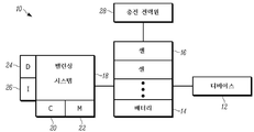
도 1은 본 원리에 따른 예시적인 시스템의 블록도;
도 2는 다수의 셀이 직렬로 연결된 리튬-이온 배터리와 같은 배터리를 충전하는 동안 셀 전압을 밸런싱하기 위한 회로의 개략도; 및
도 3은 예시적인 실시형태에 따른 예시적인 논리 흐름도.1 is a block diagram of an exemplary system according to the present principles;
2 is a schematic diagram of a circuit for balancing cell voltages while charging a battery such as a lithium-ion battery in which multiple cells are connected in series; And
3 is an exemplary logic flow diagram according to an exemplary embodiment.
본 발명은 일반적으로 배터리 충전에 관한 것으로서, 특히 동적 임피던스가 낮은 셀을 사용하는 재충전 가능한 배터리를 충전하는 것과 관련되며, 이 배터리의 하나의 실시예는 리튬-이온 배터리이다. 본 발명의 시스템은 배터리, 배터리에 의해 전력을 공급받는 구성 요소, 및 충전을 제어하기 위해 하나 이상의 컴퓨팅 구성 요소를 포함할 수 있는 충전 조립체를 포함할 수 있다. 충전 조립체는 본 원리에 따라 충전을 제어하도록 조립체를 구성하는 명령을 실행하는 하나 이상의 프로세서를 포함할 수 있다. 본 명세서에 사용된 바와 같이, 명령은 시스템에서 정보를 처리하기 위해 컴퓨터로 구현되는 단계를 지칭한다. 명령은 소프트웨어, 펌웨어 또는 하드웨어로 구현될 수 있으며, 시스템의 구성 요소에 의해 수행되는 임의의 유형의 프로그래밍된 단계를 포함한다.The present invention relates generally to battery charging, and particularly to charging rechargeable batteries using cells with low dynamic impedance, one embodiment of which is a lithium-ion battery. The system of the present invention can include a battery, a component powered by the battery, and a charging assembly that can include one or more computing components to control charging. The charging assembly can include one or more processors that execute instructions to configure the assembly to control charging according to the present principles. As used herein, instructions refer to computer-implemented steps for processing information in a system. Instructions may be implemented in software, firmware or hardware, and include any type of programmed steps performed by components of the system.
프로세서는 어드레스 라인, 데이터 라인, 및 제어 라인과 레지스터 및 시프트 레지스터와 같은 다양한 라인에 의해 논리를 실행할 수 있는 임의의 종래의 범용 단일 또는 다중 칩 프로세서일 수 있다.The processor can be any conventional general purpose single or multi-chip processor capable of executing logic by address lines, data lines, and control lines and various lines such as registers and shift registers.
본 발명의 흐름도 및 사용자 인터페이스를 통해 기술된 소프트웨어 모듈은 다양한 서브 루틴, 절차 등을 포함할 수 있다. 본 발명을 제한하지 않고, 특정 모듈에 의해 실행되는 것으로 언급된 논리는 다른 소프트웨어 모듈로 재분배되거나 되고/되거나 단일 모듈로 함께 결합되고/되거나 공유 가능한 라이브러리에서 이용 가능할 수 있다.The software module described through the flow chart and user interface of the present invention may include various subroutines, procedures, and the like. Without limiting the invention, logic referred to as being executed by a particular module may be redistributed into other software modules and/or available in a library that is combined and/or shared together as a single module.
본 명세서에 기술된 본 원리는 하드웨어, 소프트웨어, 펌웨어 또는 이들의 조합으로 구현될 수 있으며; 따라서, 예시적인 구성 요소, 블록, 모듈, 회로 및 단계는 그 기능 측면에서 제시된다.The principles described herein can be implemented in hardware, software, firmware, or a combination thereof; Accordingly, exemplary components, blocks, modules, circuits, and steps are presented in terms of their functionality.
위에서 언급된 것에 더하여, 이하에 설명되는 논리 블록, 모듈 및 회로는 본 명세서에 기술된 기능을 수행하도록 설계된 범용 프로세서, 디지털 신호 프로세서(DSP), 전계 프로그래밍 가능 게이트 어레이(FPGA) 또는 다른 프로그래밍 가능 논리 디바이스, 또는 주문형 집적 회로(ASIC), 이산 게이트 또는 트랜지스터 논리 회로, 이산 하드웨어 컴포넌트, 또는 이들의 임의의 조합으로 구현되거나 수행될 수 있다. 프로세서는 제어기 또는 상태 머신, 또는 컴퓨팅 디바이스의 조합에 의해 구현될 수 있다.In addition to those mentioned above, the logic blocks, modules and circuits described below are general purpose processors, digital signal processors (DSPs), electric field programmable gate arrays (FPGAs) or other programmable logic designed to perform the functions described herein. It may be implemented or implemented as a device, or an application specific integrated circuit (ASIC), discrete gate or transistor logic circuit, discrete hardware component, or any combination thereof. The processor may be implemented by a controller or state machine, or a combination of computing devices.
아래 설명된 기능과 방법은 소프트웨어로 구현될 때 C#이나 C++를 포함하지만 이들로 제한되지 않는 적절한 언어로 작성될 수 있으며, 랜덤 액세스 메모리(RAM), 판독 전용 메모리(ROM), 전기적으로 소거 가능한 프로그래밍 가능 판독 전용 메모리(EEPROM), 콤팩트 디스크 판독 전용 메모리(CD-ROM) 또는 다른 광 디스크 저장 매체, 예를 들어, 디지털 다용도 디스크(DVD), 자기 디스크 저장 매체 또는 다른 자기 저장 디바이스, 예를 들어, 이동식 엄지 드라이브 등을 포함하는 저장 디바이스와 같은 컴퓨터 판독 가능 저장 매체에 저장되거나 이를 통해 전송될 수 있다. 연결은 컴퓨터 판독 가능 매체를 수립할 수 있다. 이러한 연결은 예로서 광섬유 및 동축 와이어 및 디지털 가입자 회선(DSL) 및 트위스트 페어 와이어를 포함하는 유선 케이블을 포함할 수 있다.The features and methods described below, when implemented in software, can be written in any suitable language, including but not limited to C# or C++, random access memory (RAM), read-only memory (ROM), electrically erasable programming Possible read-only memory (EEPROM), compact disk read-only memory (CD-ROM) or other optical disk storage medium, for example, a digital versatile disk (DVD), magnetic disk storage medium or other magnetic storage device, for example, It may be stored on or transmitted through a computer readable storage medium, such as a storage device including a removable thumb drive or the like. The connection can establish a computer readable medium. Such connections may include, for example, fiber optic and coaxial wires and wired cables including digital subscriber line (DSL) and twisted pair wires.
일 실시형태에서 포함된 구성 요소는 다른 실시형태에서 임의의 적절한 조합으로 사용될 수 있다. 예를 들어, 본 명세서에 기술되고/되거나 도면에 도시된 다양한 구성 요소 중 임의의 구성 요소는 다른 실시형태에서 결합, 교환 또는 배제될 수 있다.The components included in one embodiment may be used in any suitable combination in other embodiments. For example, any of the various components described herein and/or illustrated in the drawings may be combined, exchanged, or excluded in other embodiments.
"A, B 및 C 중 적어도 하나를 갖는 시스템"(마찬가지로 "A, B 또는 C 중 적어도 하나를 갖는 시스템" 및 "A, B, C 중 적어도 하나를 갖는 시스템")은 A 단독, B 단독, C 단독, A와 B 함께, A와 C 함께, B와 C 함께 및/또는 A, B 및 C 함께 등을 갖는 시스템을 포함한다."A system having at least one of A, B, and C" (similarly, "a system having at least one of A, B, or C" and "a system having at least one of A, B, C") are A alone, B alone, Systems having C alone, A and B together, A and C together, B and C together and/or A, B and C together, and the like.
다음 용어들이 본 명세서에 사용될 수 있다:The following terms may be used herein:
배터리 용량 - 배터리에서 이용 가능한 에너지의 양으로, 일반적으로 더 큰 배터리의 경우 암페어시(Amp-hour: Ah) 또는 와트시(Watt-hour: Wh)로 표시된다.Battery capacity-The amount of energy available in the battery, usually expressed in amp-hours (Ah) or watt-hours (Wh) for larger batteries.
셀 - 일반적으로 애노드, 캐소드, 전해질 및 분리기로 구성된 전기 에너지 저장 유닛이다. 배터리는 단일 셀로 구성되거나 또는 직렬로 및/또는 병렬로 연결된 많은 셀로 구성될 수 있다. 배터리 밸런싱의 상황에서, 병렬로 연결된 셀 그룹은 단일 대형 셀로 취급된다.Cell-an electrical energy storage unit, usually composed of an anode, a cathode, an electrolyte and a separator. The battery may consist of a single cell or of many cells connected in series and/or in parallel. In the context of battery balancing, groups of cells connected in parallel are treated as a single large cell.
충전 상태(State of Charge: SOC) - 임의의 주어진 순간에 셀 또는 배터리에서 이용 가능한 에너지의 양으로, 일반적으로 최대 배터리 용량(FBC)의 백분율로 표시된다.State of Charge (SOC)-The amount of energy available in a cell or battery at any given moment, usually expressed as a percentage of the maximum battery capacity (FBC).
건강 상태(State of Health: SOH) - 새 배터리의 공칭 배터리 용량에 대한 배터리의 현재 최대 배터리 용량(FBC)을 나타낸다. 예를 들어, 배터리(새 배터리)의 공칭 용량이 200Ah이고 일정 기간 사용 후 FBC가 160Ah로 떨어진 경우 배터리의 SOH는 80%이다.State of Health (SOH)-indicates the current maximum battery capacity (FBC) of the battery relative to the nominal battery capacity of the new battery. For example, if the nominal capacity of the battery (new battery) is 200 Ah and the FBC drops to 160 Ah after a period of use, the SOH of the battery is 80%.
1차 충전 경로 - 일련의 배터리 셀 바로 아래의 충전 경로를 나타낸다.Primary charging path-represents the charging path just below a series of battery cells.
밸런스 - 단자 충전 단계에서 셀 전압이 등화되어 모든 셀(여기서 "셀"은 병렬로 연결된 개별 셀 그룹일 수 있음)이 최대 충전 전압에 있고 나서 충전이 계속되어 일반적으로 밸런싱 전류가 아래에 더 설명된 바와 같이 배터리가 밸런싱이 맞는 지점인 낮은 임계값 레벨로 떨어졌을 때 배터리는 밸런싱이 맞춰진다.Balance-In the terminal charging phase, the cell voltage is equalized so that all cells (where "cells" can be individual groups of cells connected in parallel) are at the maximum charging voltage and then charging continues, so that the balancing current is generally described further below. As shown, when the battery drops to a low threshold level, which is the point at which it is balanced, the battery is balanced.
등화 - 배터리 밸런싱을 맞추기 위해 충전 및 밸런싱 프로세스 동안 셀 전압의 차이를 줄이는 프로세스를 설명하는 데 사용된다.Equalization-used to describe the process of reducing the difference in cell voltage during the charging and balancing process to match battery balancing.
"밸런싱이 맞는" 및 "밸런싱이 맞지 않는"은 상대적인 용어라는 것이 주목된다. 본 목적을 위해, 배터리 내 모든 셀의 SOC가 서로 대략 ±1% 내에 있으면 배터리는 밸런싱이 맞는 것으로 고려된다.It is noted that "balanced" and "unbalanced" are relative terms. For this purpose, the batteries are considered to be balanced if the SOC of all cells in the battery is within approximately ±1% of each other.
밸런싱 전류 - 셀의 밸런싱을 맞추기 위해 배터리 내 셀의 서브세트에 적용된 충전(또는 방전) 전류의 차이를 나타낸다.Balancing Current-Shows the difference in charge (or discharge) current applied to a subset of cells in the battery in order to balance the cells.
밸런싱 레그 - 1차 충전 경로에서 분리되고 배터리 밸런싱을 맞추기 위해 셀의 서브세트에 충전 또는 방전 전류를 인가하는 데 사용되는 전도성 경로를 나타낸다.Balancing Leg-represents a conductive path that is separated from the primary charge path and used to apply charge or discharge current to a subset of cells to match battery balancing.
참된(true) 배터리 용량 - 배터리 내 모든 셀이 100% SOC로 충전될 때의 배터리 용량이다.True battery capacity-the battery capacity when all cells in the battery are charged to 100% SOC.
이용 가능한 배터리 용량 - 임의의 주어진 순간의 배터리 용량.Available battery capacity-Battery capacity at any given moment.
공칭 배터리 용량 - 새 배터리의 공칭 용량을 나타낸다.Nominal battery capacity-indicates the nominal capacity of the new battery.
최대 배터리 용량 - 충전 시스템이 할 수 있을 만큼 최대로 충전 시스템이 배터리를 충전한 후 배터리의 이용 가능한 용량을 나타낸다.Maximum battery capacity-represents the available capacity of the battery after the charging system has charged the battery to the maximum extent that the charging system can.
참된 배터리 용량 대 최대 배터리 용량 - 충전 시스템이 전체 충전 사이클이 끝날 때 모든 셀을 100% SOC까지 올릴 수 없거나 올리지 못한 경우 최대 배터리 용량은 참된 배터리 용량보다 더 적다.True battery capacity vs. maximum battery capacity-If the charging system cannot or cannot raise all cells to 100% SOC at the end of the entire charging cycle, the maximum battery capacity is less than the true battery capacity.
셀 전압 - 임의의 순간의 셀 전압.Cell voltage-the cell voltage at any instant.
공칭 전압 - 방전 곡선의 평탄한 영역에 걸쳐 셀 또는 배터리의 평균 또는 평균 전압.Nominal voltage-the average or average voltage of a cell or battery over a flat area of the discharge curve.
최대 충전 전압 - 충전 사이클이 끝나갈 때 셀 또는 배터리에 공급되는 전압.Maximum charging voltage-the voltage supplied to the cell or battery at the end of the charging cycle.
셀 임피던스 - 셀 전압을 셀 전류로 나눈 값을 지칭한다.Cell impedance-refers to the value of the cell voltage divided by the cell current.
동적 임피던스 - 전류에 대한 전압의 1계 미분 - dV/dI.Dynamic impedance-1st derivative of voltage to current-dV/dI.
이제 도 1을 구체적으로 참조하면, 예시적인 시스템(10)이 도시되고, 시스템은 본 원리에 따라 위에서 언급되고 아래에서 더 설명되는 예시적인 디바이스 중 하나 이상을 포함할 수 있다. 시스템(10)에 포함된 예시적인 디바이스 중 제1 디바이스는 가전(CE) 디바이스, 예를 들어, 태블릿 컴퓨터, 노트북 컴퓨터, 웨어러블 컴퓨터화된 디바이스, 컴퓨터화된 인터넷 가능 팔찌, 다른 컴퓨터화된 인터넷 가능 디바이스, 컴퓨터화된 인터넷 가능 음악 플레이어, 컴퓨터화된 인터넷 가능 헤드폰, 컴퓨터화된 인터넷 가능 이식 가능 디바이스, 예를 들어, 이식 가능 피부 디바이스 등과 같은 디바이스(12)이다. 다른 예시적인 디바이스(12)는 전기 차량, 산업 전력 시스템, 및 전력망 또는 구조 전기 시스템에 사용되는 저장 디바이스에서 에너지 저장 모듈(예를 들어, 배터리 어레이)을 포함한다.Referring now specifically to FIG. 1, an example system 10 is shown, and the system may include one or more of the example devices mentioned above and further described below in accordance with the present principles. The first of the exemplary devices included in the system 10 is a consumer electronics (CE) device, such as a tablet computer, a notebook computer, a wearable computerized device, a computerized internet enabled bracelet, and other computerized internet enabled It is a
디바이스(12)는 복수의 셀(16)이 서로 전기적으로 직렬로 연결된 리튬-이온 배터리와 같은 재충전 가능 배터리(14)에 의해 전력을 공급받을 수 있고, 여기서는 단 하나의 연결(18)만이 배터리(14)와 디바이스(12) 사이에 도시되어 있지만 일반적으로 하나를 초과하는 전기 라인이 배터리를 디바이스에 연결하는 것으로 이해된다. 배터리(14)는 디바이스(12)의 하우징에 제거 가능하게 또는 제거 가능하지 않게 결합될 수 있다. 리튬-이온 배터리는 리튬 철 인산염, 리튬 코발트 산화물, 리튬 니켈 망간 코발트 산화물, 리튬 이온 망간 산화물, 리튬 니켈 코발트 알루미늄 산화물, 리튬 티타네이트, 또는 리튬 이온을 사용하는 전해질을 포함한 임의의 다른 배터리 화학 물질과 같은 리튬계 전해질을 사용하는 임의의 배터리에 의해 구현될 수 있다. 본 원리는 예시적인 실시형태에서 리튬 이온 배터리와 관련하여 사용하는 것을 고려하지만, 본 원리는 임의의 적절한 저장된 에너지 원 또는 저장 요소, 특히 (비-제한적으로) 충전/방전 동안 낮은 동적 임피던스 특성을 나타내는 것에 사용하는 것을 고려한다.The
아래에서 더 논의되는 바와 같이, 밸런싱 시스템(18)은 배터리(14)를 충전하거나 또는 방전하는 동안 배터리(14)에 전기적으로 연결될 수 있다. 밸런싱 시스템(18)은 디바이스(12)의 하우징 내에 전체적으로 또는 부분적으로 통합될 수 있거나 이와 분리될 수 있다. 밸런싱 시스템(18)은 배터리 케이스 내에 봉함되거나 배터리 케이스 외부에 배치될 수 있다.As discussed further below, the balancing
이하에서 보다 완전히 개시되는 밸런싱 시스템(18)의 구성 요소 중에는 적어도 하나의 제어기(20) 및 적어도 하나의 데이터 저장 매체(22)가 있다. 원하는 경우, 밸런싱 시스템(18)은 또한 액정 디스플레이(LCD)와 같은 하나 이상의 디스플레이(24), 및 네트워크 인터페이스, 범용 직렬 버스(USB) 포트, 키 입력 디바이스 등과 같은 하나 이상의 입력 디바이스(26)를 더 포함할 수 있다. 네트워크 인터페이스는 인터넷, 광역 네트워크 또는 근거리 네트워크, Wi-Fi 네트워크, 무선 전화 네트워크, 블루투스 네트워크 등과 같은 하나 이상의 네트워크를 통한 통신을 제공할 수 있다. Among the components of the
데이터 메모리(22)는 비-제한적으로 일시적인 신호가 아닌 디스크 기반 또는 솔리드 스테이트 저장 매체일 수 있다. 메모리는 이동식 매체일 수 있다.The
어쨌든, 아래에서 더 논의되는 바와 같이, 밸런싱 시스템(18)은 충전 전력원(28)으로부터 충전하는 동안 개별 셀(16)의 전압을 등화하도록 동작한다.In any case, as discussed further below, balancing
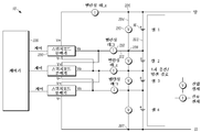
이제 예시적인 밸런싱 시스템(18)의 보다 상세한 묘사를 위해 도 2를 참조하면, 밸런싱 시스템(18)은 복수의 스위치 모드 분배기(SMD)(200)를 포함한다. 본 명세서에서 이해되는 바와 같이, SMD(200)를 사용하는 밸런싱 시스템은 덜 효율적인 밸런싱 시스템의 한계를 극복할 수 있다. 스위치 모드 설계의 낮은 임피던스 전류 경로는 효율을 크게 향상시키지만, 이것은 높은 루프 이득을 갖는 제어 시스템을 생성하여, 제어 루프를 셀(16)의 전압의 가장 작은 차이에도 매우 민감하게 한다. 밸런싱 시스템(18)의 후술하는 밸런싱 레그(212)의 전류 센서(218)는 밸런싱 레그(212)의 전류가 밸런싱 시스템(18)에 대해 후술되는 임계값(들)에 의해 지정된 임계 범위 내에 있는지 여부를 결정하는 데 사용된다. 이러한 회로 측정을 통해 밸런싱 시스템(18)은 회로의 루프 이득을 제한하여, 고 이득 루프를 보다 효과적으로 제어할 수 있다.Referring now to FIG. 2 for a more detailed depiction of an
일반적으로 그리고 밸런싱 시스템(18)의 세부 사항을 설명하기 전에, SMD(200)는 고전력(저 임피던스) 전압 분배기이다. 제어 출력 전압(Vo)은 구동 파형의 듀티 사이클과 높은 및 낮은 레일 전압의 함수이다.In general and before describing the details of the
스위치 모드 회로 기술에 따르면, 각각의 SMD(200)는 고유한 ON 시간 및 OFF 시간을 갖는 일정한 기간의 신호(period signal)에 의해 구동되며, 두 시간의 합은 총 일정 기간과 본질적으로 항상 동일하다. SMD 변조는 ON 시간 대 총 기간의 비율(듀티 사이클이라고도 함)이 제어 출력 전압(Vo)을 직접 대응하여 변화시키도록 조절된다는 점에서 펄스 폭 변조의 형태를 갖는다.According to the switch mode circuit technology, each
듀티 사이클이 50%인 경우 출력 전압은 높은 레일 전압과 낮은 레일 전압 사이의 중간 지점에 있다. SMD 기반 밸런싱 시스템(18)의 임피던스가 낮으면 비교적 큰 밸런싱 전류 레벨이 매우 높은 효율로 셀(16)에 인가될 수 있다. SMD(200)와 Li-이온 셀(16)은 본질적으로 병렬로 연결된 매우 낮은 임피던스 디바이스이기 때문에, 작은 전압 차이를 생성하는, 듀티 사이클의 매우 작은 변화로도 상대적으로 높은 대응하는 레벨의 차동 밸런싱 레그 전류를 생성할 수 있다. 저 임피던스 셀을 충전 및/또는 밸런싱을 맞추기 위해 저 임피던스 셀의 전압을 변화시키면, 결과적으로 높은 이득 응답이 밸런싱 시스템에 피드백 불안정성을 야기할 수 있는 데, 이 문제는 밸런싱 레그(212)에 후술하는 전류 센서(218)를 사용함으로써 해결된다. When the duty cycle is 50%, the output voltage is halfway between the high and low rail voltages. If the impedance of the SMD-based
따라서, 도 2의 세부 사항으로 돌아가면, 4개의 배터리 셀이 도시된 예에서 복수의 배터리 셀(16)은 1차 충전/방전 경로(202)를 형성하도록 도시된 바와 같이 서로 전기적으로 직렬로 배열된다. 밸런싱 회로(18)는 도시된 바와 같이 1차 충전/방전 경로(202)와 전기적으로 병렬로 배열된다.Thus, returning to the details of FIG. 2, in the example where four battery cells are shown, a plurality of
밸런싱 회로(18)는 1차 충전/방전 경로(202)와 병렬로 밸런싱 라인(204)을 포함한다. 밸런싱 라인(204)은 제1 SMD(200)의 "높은" 또는 양의 측(도 2에서 최상위에 V+로 표시)이 전기적으로 결합된 양의 노드(206), 및 마지막 SMD(200)의 "낮은" 또는 음의 측(도 2에서 최하위에 V-로 표시)이 전기적으로 결합된 음의 노드(207)를 포함한다. 각각의 SMD(200)의 제어 출력(Vo)은, 도시된 바와 같이 각각의 전류 센서(218)를 포함하고 인접한 셀(16)들 사이의 각각의 셀 접합부(208)에서 종료하는 각각의 밸런싱 레그(212)에 연결된다. 예시적인 실시형태에서, N개의 셀(16)에 대해 총 N-1개의 SMD(200)가 제공된다는 것이 주목된다. 또한, 위에서 아래로 가면서, 최상위 SMD(200)의 음의 측(V-)이 그 다음 (도시된 예에서 중간) SMD(200)의 제어 출력 전압(Vo)에 연결되는 반면, 중간 SMD(200)의 양의 측(V+)은 최상위 SMD의 제어 출력 전압(Vo)에 연결되며, 이러한 패턴은 도시된 바와 같이 SMD 아래로 전파된다는 것이 주목된다.The balancing
다시 말해, 각 SMD(200)의 양의 레일(V+)은 직렬 연결에서 그 다음 가장 높은 밸런싱 레그(212)에 연결되고, 또는 직렬 연결에서 더 높은 밸런싱 레그가 없다면 양의 노드(206)에 연결된다. 각 SMD(200)의 음의 레일(V-)은 직렬 연결에서 그 다음 가장 낮은 밸런싱 레그(212)에 연결되고, 또는 직렬 연결에서 더 낮은 밸런싱 레그가 없다면 음의 노드(207)에 연결된다. 각각의 SMD(200)의 제어 출력 전압(Vo)은 전류 센서를 통해 각각의 셀 접합부(208)로 전달하는 밸런싱 레그(212)에 연결된다.In other words, the positive rail (V+) of each
각각의 전압 센서(210)는 각각의 셀(16)과 전기적으로 병렬로 각각의 개별 셀 접합부(208) 사이의 밸런싱 라인(204)에 있으며, 각각의 셀(16)에 걸친 전압을 나타내는 신호를 생성한다. 전압 센서(210)는 제어기(220)가 각각의 전압 센서(210)로부터 전압 정보를 수신할 수 있도록 아래에서 더 설명된 제어기(220)에 통신 가능하게 결합된다.Each
각각의 SMD(200)의 제어 출력 전압(Vo)은 각각의 셀의 전압 센서(210)와 전기적으로 병렬로 밸런싱 라인의 각각의 셀 접합부(208)에 각각의 밸런싱 레그(212)를 통해 연결된다. 일부 실시예에서, 밸런싱 레그(212)는 Vo를 각각의 셀 접합부(208)에 연결하는, 도시된 노드들 사이에 도시된 전기 회로로 구성된다. 각각의 전류 센서(218)는 각각의 SMD(200)로부터의 제어 출력 전압(Vo)과 각 셀 접합부(208) 사이에 전기적으로 직렬로 밸런싱 레그(212)에 전기적으로 연결되고, 각 밸런싱 레그(212)를 통한 전류를 나타내는 신호를 생성한다. 양의 노드(206)를 포함하는 최상위 양의 라인에서 도 2에 도시된 전류 센서(218)는 선택 사항이라는 것이 주목된다. 각각의 전류 센서(218)는 제어기가 전류 센서(218)로부터 밸런싱 레그 전류 정보를 수신할 수 있도록 아래에서 논의된 제어기(220)에 통신 가능하게 결합된다.The control output voltage Vo of each
따라서, 적어도 하나의 제어기(220), 바람직하게는 디지털 마이크로제어기는, 아래에서 더 설명된 바와 같이 밸런싱 레그(212) 상의 전류를 특정 한계 내로 유지하도록 각각의 셀(16)에 대한 1차 충전 경로(202) 상의 전압에 가감되는 각 SMD(200)의 제어 출력 전압(Vo)을 수립하도록 SMD(200)를 변조하기 위해 SMD(200)에 연결된다.Thus, at least one
제어 출력 전압(Vo)을 수립할 때, SMD(200)의 듀티 사이클은 위에서 논의되고 아래에서 더 설명된 바와 같이 출력 전압을 상승시키기 위해 증가되고 출력 전압을 낮추기 위해 감소된다.When establishing the control output voltage Vo, the duty cycle of the
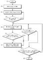
도 3은 도 2에 도시된 밸런싱 시스템(18)의 동작을 도시한다. 프로세스는 시작 상태(300)에서 시작된다. 배터리 충전은 블록(302)에서 각각의 셀(16)이 임의의 SOC 상태에 있고 셀(16)이 일반적으로 최대 충전 전압 미만에서 밸런싱이 맞거나 또는 밸런싱이 맞지 않는 임의의 상태에 있는 배터리(14)에 대해 시작된다. 블록(304)은 1차 충전/방전 경로(202) 상의 양의 단자로부터 음의 단자로 흐르는, 바람직하게는 최대 임계 레벨의 충전 전류가 인가됨으로써 충전이 시작되는 것을 나타낸다. 1차 충전 경로 전류의 최대 임계 레벨은 밸런싱 레그 임계 전류와 동일할 것이 요구되지 않는다. 2개의 임계 전류는 임의의 특정 구현에서 동일하거나 상이할 수 있다.3 shows the operation of the
각각의 셀(16)의 전압은 각각의 전압 센서(210)를 사용하여 모니터링되고, 결정 마름모꼴(306)에서 적어도 하나의 셀(16)이 최대 충전 전압(FCV)에 도달하거나 이를 초과한다고 결정되면, 논리는 셀 전압을 등화하도록 SMD(200)를 변조하기 위해 블록(308)으로 진행한다. 즉, 예시적인 구현예에서, 후술되는 전류 제한 동작을 갖는 셀 등화는 제1 셀이 FCV에 도달할 때에만 시작된다. 다른 실시형태에서, 전류 센서로부터의 입력은 배터리 충전 동안 적어도 하나의 셀이 최대 충전 전압에 도달하기 전에 밸런싱 레그를 통한 전류가 임계 전류 크기 이하가 되도록 제한하기 위해 제어기에 의해 사용된다.The voltage of each
셀(16)이 셀(16)의 각각의 전압 센서(210)에 의해 지시된 바와 같이 최대 충전 전압을 초과하는 전압에 도달하면, 제어기(220)는 전압이 FCV에 있거나 이 FCV 바로 아래에 있을 때까지 제어된 율로 셀의 전압을 등화하기 위해 과전압 셀(16)과 관련된 SMD(200)를 변조하는 것에 의해 셀(16)의 전압을 낮춘다.When the
SMD(200)가 셀 전압을 변조하기 위해 사용될 때, 논리는 결정 마름모꼴(310)에서 임의의 밸런싱 레그 전류 센서(218)에 의해 측정된 전류의 크기(양 또는 음)가 임계값, 일반적으로 최대 허용 전류 크기 이상인지 여부를 결정한다. 이는 밸런싱 전류가 임의의 방향으로 흐를 수 있기 때문에 음의 전류 및 양의 전류를 모두 제한하기 위해 적용된다. 하나의 임계값은 음의 전류에 사용될 수 있고, 또 하나의 다른 임계값은 양의 전류에 사용될 수 있고, 또는 단일 임계값이 이 둘 모두에 적용될 수 있다는 것이 주목된다. 임의의 밸런싱 레그 전류의 크기가, 예를 들어, 과도한 변화율로 블록(308)에서 변조를 적용한 결과, 결정 마름모꼴(310)에서, 예를 들어, 임계값 이상인 것에 의해 임계값을 충족하는 경우, 논리는 블록(312)으로 이동하여 밸런싱 레그 전류 크기를 임계값 이하로 유지하면서 셀(16)들 사이의 전압 차를 감소시키도록 인접한 셀(16)의 전압을 조절하도록 SMD(200)를 변조한다.When the
다시 말해, 밸런싱 프로세스 동안 언제라도, 셀 전압을 등화하기 위해 제어 출력 전압(Vo)을 제어하는 것은 임의의 밸런싱 레그(212)의 전류의 크기가 한계 임계값 이상이 되는 방식으로 조절되면, 과도 전류를 갖는 밸런싱 레그(212)에 있거나 및/또는 이 밸런싱 레그에 인접하는 SMD(200)를 변조하는 것은 과도 밸런싱 전류를 갖는 셀(16)과 하나 또는 둘 모두의 인접 셀(16) 사이의 전압 차이를 감소시키도록 조절된다.In other words, controlling the control output voltage Vo to equalize the cell voltage at any time during the balancing process, if the magnitude of the current in any balancing
제어기(220)는 밸런싱 레그 전류 크기의 임계값을 위반하지 않으면서 가장 빠른 충전 및 밸런싱을 제공하도록 밸런싱 전류의 허용된 크기를 가능한 한 많이 항상 최대 허용 임계값 아래로 수립하는 것이 바람직하다. 따라서, 예시적인 실시형태에서, 밸런싱 전류 크기는 셀(16)을 손상시키거나 안전 위험을 야기할 수 있는 과전류 상태를 방지하기 위해 임계값 이하의 높은 레벨로 유지된다.It is desirable that the
전압 및 전류 데이터의 상기 모니터링 및 SMD의 변조는 바람직하게는 적어도 하나 이상의, 바람직하게는, 2개의 조건이 충족될 때까지 계속된다. 결정 마름모꼴(314)에 지시된 바와 같이, 모든 셀(16)이 FCV에 도달했는지 여부가 결정된다. 만약 그렇지 않은 경우, 프로세스는 블록(308)으로 되돌아간다. 모든 셀이 FCV에 도달한 경우, 논리는 결정 마름모꼴(314)로부터 결정 마름모꼴(315)로 이동하여 각 셀에 대한 전류가 참된 배터리 용량에 도달한 배터리(14)를 나타내는 레벨로 감소했는지 여부를 결정할 수 있다. 만약 그렇다면, 프로세스는 상태(316)에서 종료한다. 만약 그렇지 않은 경우, 논리는 블록(308)으로 되돌아간다.The monitoring of the voltage and current data and modulation of the SMD preferably continues until at least one, preferably two conditions are met. As indicated by
SMD(200)를 변조할 때, 제어기(220)가, 밸런싱 레그 전류 센서(218)로부터의 신호에 기초하여, 밸런싱 레그(212)에 흐르는 전류가 양의 방향으로 (예를 들어, SMD(200)로부터 각각의 셀(16)로 가는 방향으로) 너무 높다고 (예를 들어, 임계값보다 높다고) 결정하면, SMD(200)의 듀티 사이클이 감소되어 제어 출력 전압(Vo)을 낮춘다. 한편, 밸런싱 레그(212)의 전류가 음의 방향으로 너무 큰 경우, 제어기는 SMD(200)를 변조하여 듀티 사이클을 증가시켜 제어 출력 전압(Vo)을 상승시킨다.When modulating the
제어기(220)는 밸런싱 레그 전류 크기를 밸런싱 전류의 임계값 이하로 유지하면서 셀 전압을 등화하기 위해 SMD(200)를 계속 변조하기 위해 전압 센서(210)에 의해 지시된 바와 같이 모든 셀 전압을 샘플링한다는 것이 주목된다. 임의의 하나의 셀(16)에서 SMD 제어 출력 전압(Vo)이 변경될 때, 이것은 셀(16)들이 직렬로 연결되어 있는 것으로 인해 인접한 셀(16)들 및 인접한 밸런싱 레그 전류들에 영향을 미쳐서, SMD(200)의 출력 전압을 변조 및 조절하는 것은 일반적으로 밸런싱 시스템(18)이 동작하는 동안 계속되는 프로세스이다.The
원하는 경우, 밸런싱 레그 전류에 대한 임계값 크기는 배터리 용량, 배터리의 화학 물질, 배터리의 설계, 원하는 밸런싱 범위 및 사용 환경의 함수로서 수립될 수 있다. 일반적으로, 밸런싱 레그 전류의 임계 크기는 배터리 시스템의 설계 목표에 기초하여 최대 허용 충전 전류의 적절한 백분율이 되도록 선택된다. 더 높은 밸런싱 전류 임계값은 셀(16)이 더 짧은 시간에 밸런싱이 맞는 상태에 도달할 수 있게 하지만, 너무 높은 임계값은 셀 손상을 초래할 수 있어서, 임계값은 밸런싱 레그(212)의 전류가 셀 스트레스 레벨 아래로 유지되도록 수립된다.If desired, the threshold size for the balancing leg current can be established as a function of battery capacity, battery chemistry, battery design, desired balancing range and usage environment. Generally, the threshold size of the balancing leg current is selected to be an appropriate percentage of the maximum allowable charging current based on the design goal of the battery system. A higher balancing current threshold allows the
일례로서, 더 큰 배터리에서 최대 1차 충전 전류의 5% 내지 10%의 밸런싱 전류 범위 임계값이 일반적으로 발생할 수 있는 배터리(14)와 셀(16)의 조건 하에서 1 시간 또는 2 시간 내에 100% 밸런싱을 보장하기에 충분하다. 셀(16)의 SOC가 서로 더 가까울수록, 임의의 주어진 시간 기간에 걸쳐 완전한 밸런싱을 달성하는데 필요한 밸런싱 범위가 더 낮아진다. 일부 설계자들은 예를 들어 비용을 절약하기 위해 2% 내지 3%의 낮은 범위를 선택할 수 있지만, 더 빠른 밸런싱 시간이 시스템 비용보다 더 중요한 경우 다른 사람들은 더 높은 범위(예를 들어, 20% 또는 30%)를 선택할 수 있다.As an example, in a larger battery, a balancing current range threshold of 5% to 10% of the maximum primary charging current may occur 100% within 1 hour or 2 hours under conditions of the
이제 밸런싱 레그(212)의 전류는 1차 충전 경로(202)에 있는 각 셀(16)을 충전하는 전류의 프록시(proxy)로서 유리하게 사용될 수 있는 것으로 이해될 수 있다. 본 명세서에서 이해되는 바와 같이, 밸런싱 레그(212)의 전류는 각각의 셀(16)이 100% SOC에 도달했을 때를 결정하는 데 사용될 수 있는 1차 충전 경로(202)의 주 충전 전류와 충분히 근접하게 상관된다. 이것은 전류 센서(218)가 밸런싱 레그(212) 상에 배치될 수 있게 하고, 1차 충전 경로(202)의 전류를 감지하는 데 필요할 수 있는 것보다 훨씬 낮은 정격 전류를 갖는 전류 센서(218)를 사용할 수 있게 한다. 2개의 입력, 즉 밸런싱 레그(212)의 전류 및 각 셀(16)의 전압을 사용하면 (스위치 모드 회로로부터) 매우 높은 효율을 가능하게 하고 (전류 센서(218)의 추가로부터) 매우 우수한 안정성을 가능하게 한다. 또한, 회로(18)는 모든 전체 충전 사이클이 끝날 때 배터리(14) 내의 모든 셀(16)을 100% SOC까지 신뢰성 있고 효율적이며 정확하게 올릴 수 있다. 다시 말해, 셀 전압 및 밸런싱 레그 전류를 모니터링함으로써, 제어기(220)는 셀(16)이 최대 충전 전압에 도달하고 나서 100% SOC에 도달할 때를 검출할 수 있다. 셀(16)이 처음 최대 충전 전압에 도달할 때에는, 셀이 일반적으로 아직 100% SOC에 있지 않아서, 셀을 100% SOC까지 올리기 위해 일반적으로 최대 충전 전압 이후에 추가 충전이 필요하며, 이는 밸런싱 레그 전류 센서(218)의 입력에 의해 가능하고, 이에 의해 셀(16)이 100% SOC에 도달한 때를 정확하고 신뢰성 있게 결정할 수 있다. 100% SOC를 지시하는 것은 셀(16)이 각각의 전압 센서(210)에 의해 지시된 바와 같이 최대 충전 전압에 있고 셀(16)과 관련된 전류 센서(218)에 의해 지시된 바와 같이 셀(16)의 전류가 매우 낮은 레벨, 일반적으로 약 0.05C 내지 0.01C 정도만큼 낮은 레벨로 떨어졌을 때 발생하고, 여기서 "C"는 셀의 용량에 대한 전류 율의 척도이다.It can now be understood that the current of the balancing
또한, 밸런싱 레그(212) 상에 전류 센서(218)를 위치시키면 배터리의 1차 충전 경로(202)를 손상시키는 것을 회피할 수 있다.In addition, placing the current sensor 218 on the balancing
다양한 셀(16) 간의 고유한 전압 강하의 차이를 관리할 수 있는 것에 더하여, 제어기(220)에 의해 사용되는 피드백 루프에 대한 입력으로서 밸런싱 전류를 사용하면, 이 구성의 모든 추가된 장점을 유지하면서 저 임피던스 SMD(200) 구성의 불안정성 단점을 완화시킬 수 있다. 전류 센서(218)를 사용하면, 셀 전압은 대략적으로 측정되기만 하면 되는 한편, 밸런싱 레그(212)의 전류를 유한한 최대 레벨로 제한하면 높은 이득 충전 시스템의 제어 손실 가능성을 효과적으로 제거할 수 있다.In addition to being able to manage the difference in the inherent voltage drop between the
더 나아가, 전압 및 전류 측정의 정확도(또는 해상도)는 가능한 전류 폭주(runaway) 조건을 검출하고 이를 방지하기 위해 이 조건을 수정하고, 셀(16)이 최대 충전 전압을 넘어 상승하지 않고 및/또는 최대 셀 전압(셀을 손상시킬 위험을 야기함이 없이 셀을 충전할 수 있는 최대 전압)에 접근하지 않는 것을 보장할 만큼 충분히 크기만 하면 되기 때문에, 비교적 낮은 정확도(일반적으로 전압 센서(210)의 경우 최대 셀 전압의 2% 및 전류 센서(218)의 경우 0.03C의 정확도)를 갖는 전류 및 전압 센서라도 충분하다. Furthermore, the accuracy (or resolution) of the voltage and current measurements detects possible current runaway conditions and corrects them to prevent them, and the
또한, 밸런싱 레그(212) 상의 전류 센서(218)는 1차 충전 경로(202)에 배치될 수 있는 전류 센서에 비해 비교적 작고 저렴한 것으로 평가될 수 있으며; 밸런싱 레그(212) 상에 있는 전류 센서(218)는 시스템의 효율을 감소시킬 수 있는, 1차 충전 경로(202)로부터 에너지를 사이펀 오프(siphon off)하는 것을 야기하지 않으며; 1차 충전 경로 상에 있는 더 큰 전류 센서와 달리 밸런싱 레그 상에 있는 전류 센서는 과도한 열을 발생시키지 않는다.Also, the current sensor 218 on the balancing
높은 충전 전류가 충전 사이클에 걸쳐 효율적이고 안전하게 인가될 수 있기 때문에, 각 셀(16)이 최대 충전 전압에 도달할 때 충전 전류가 낮은 레벨로 떨어지는 것으로 인해, 현재 제공되는 것보다 더 빠른 충전 사이클이 회로(18)에 의해 실현된다. 또한 밸런싱 회로(18)는 상당히 밸런싱이 맞지 않는 셀(16)을 밸런싱 맞출 수 있다. 결함이 있는 셀(16)이 없는 한(본질적으로, 모든 셀이 충전될 수 있는 한), 밸런싱 회로(18)는 충전 사이클의 시작 시에 각 셀(16)의 SOC에 관계없이 배터리(14)의 모든 셀(16)을 100% SOC까지 올려서 배터리(14) 내 다른 모든 셀(16)과 밸런싱을 맞출 수 있다.Because the high charge current can be applied efficiently and safely over the charge cycle, the charge current falls to a low level when each
셀 특성이 변해도 밸런싱 회로(18)의 밸런싱 성능에는 영향을 미치지 않는다. 다시 말해, 밸런싱 회로(18)는 셀 특성이 변하는 것에 관계없이 배터리를 완전히 충전하고 밸런싱 맞출 수 있다.Even if the cell characteristics are changed, the balancing performance of the balancing
SMD(200)는 각 셀(16)이 최대 충전 전압 및 고 임피던스에 도달하여 각 셀(16)이 100% SOC에 도달할 때까지 각 셀(16)에 대한 충전 전류를 독립적으로 조절하도록 제어기(220)에 의해 변조된다. 비-제한적인 실시형태에서, 이것은 셀(16)들 사이의 전류 분기를 최소화하면서, 고전압 셀(16)을 하강시키는 것이 아니라 저전압 셀(16)을 상승시키는 셀 전압을 수립하도록 SMD(200)을 변조함으로써 셀에 가해지는 스트레스를 최소화하면서 달성될 수 있다. 일반적으로 그러나 비-제한적으로, 셀(16)은 충전 동안 밸런싱 방식의 일부로서 개별 셀(16)로부터의 방전이 거의 없거나 전혀없이, 꾸준한 상향 충전 사이클에서 방전 상태로부터 최대 충전 상태까지 올릴 수 있다.The
상기 언급된 장점에 더하여, 본 밸런싱 회로(18)는, 밸런싱을 유지하기 위해 부하 저항기를 통해 셀(16)을 방전할 필요성을 제거하고, 일부 시스템에 고유한 밸런싱 범위의 한계를 극복한다. 본 밸런싱 회로(18)는 적어도 하나의 셀(16)이 최대 충전 전압에 도달할 때에만 밸런싱 회로(18)가 스위칭온되어서 최대 주 충전 전류가 충전 사이클의 대부분 동안 인가될 수 있기 때문에 배터리의 최대 허용 전류(ampacity)의 작은 분율에 대해서만 정격된 전류 센서(218)를 사용할 수 있게 하여, 전류 감지 시스템의 비용을 감소시킨다. 이 지점에서 다른 셀(16)도 일정 시간 동안 충전되어서 일반적으로 최대 충전 전압에 가까울 수 있다. 따라서, 예시적인 실시형태에서, 셀 밸런싱은 모든 셀(16)이 최대 충전 전압에 근접할 때 각 충전 사이클의 종료 근처에서만 순간 밸런싱 회로(18)에 의해 수행되어, 셀(16)을 신속하게 밸런싱하고 모든 셀을 100% SOC로 올리는 데 소량의 밸런싱 전류만이 필요하다.In addition to the above-mentioned advantages, the
전술한 밸런싱 프로세스는 배터리 충전 동안 셀 등화를 고려하지만, 배터리 방전 동안 동일한 원리가 사용될 수도 있다. 일 실시형태에서, 제어기(220)의 논리는 방전 사이클 동안 (일반적으로 배터리(14)가 부하에 전력을 공급할 때) 배터리(14)의 셀(16)을 밸런싱 맞춘다. 따라서, 밸런싱 레그(212) 상의 전류를 제한하면서 셀 전압을 등화하는 논리는 충전 사이클 동안뿐만 아니라 방전 사이클 동안에도 이용될 수 있다.The balancing process described above considers cell equalization during battery charging, but the same principle may be used during battery discharge. In one embodiment, the logic of
본 명세서에서 이해되는 바와 같이, 방전 사이클 동안 밸런싱은 배터리(14)의 이용 가능한 용량을 증가시킬 수 있다. 배터리(14)의 셀(16)의 용량에 상당한 차이가 있는 경우(예를 들어, 가장 작은 셀이 가장 큰 셀의 90% 이하의 용량을 갖는 경우), 일반적으로 배터리를 위해 제공되는 관리 시스템은 가장 작은 셀이 최소 셀 전압에 도달한 때 부하로부터 배터리를 전기적으로 분리한다. 한편, 방전 동안 배터리의 밸런싱이 맞으면, 더 큰 용량의 셀에 저장된 에너지가 가장 작은 용량의 셀로 전송되어, 이용 가능한 배터리 용량이 증가한다.As understood herein, balancing during the discharge cycle can increase the available capacity of the
본 밸런싱 회로(18)를 이용하면, SOC를 추정할 때 고유한 부정확성을 완화하기 위해 배터리 충전 및 방전 사이클에 대한 데이터를 수집, 저장 및 분석할 필요가 없어진다.With this balancing
상기 방법은 제어기(220), 예를 들어, 프로세서, 적절하게 구성된 주문형 집적 회로(ASIC) 또는 전계 프로그래밍 가능 게이트 어레이(FPGA) 모듈, 또는 이 기술 분야에 통상의 지식을 가진 자라면 이해할 수 있는 임의의 다른 편리한 방식에 의해 실행되는 소프트웨어 명령으로 구현될 수 있다. 소프트웨어 명령은 사용되는 경우 CD ROM 또는 플래시 드라이브와 같은 비-일시적인 디바이스로 구현될 수 있다. 소프트웨어 코드 명령은 대안적으로 무선 또는 광학 신호와 같은 일시적인 배열로 구현되거나 또는 인터넷을 통한 다운로드를 통해 구현될 수 있다.The method may be understood by a
본 원리가 일부 예시적인 실시형태를 참조하여 설명되었지만, 이들 실시형태는 본 발명을 제한하는 것으로 의도된 것이 아니고, 다양한 대안적인 배열이 본 명세서에 청구된 주제를 구현하는 데 사용될 수 있는 것으로 이해된다.Although the present principles have been described with reference to some exemplary embodiments, it is understood that these embodiments are not intended to limit the invention, and various alternative arrangements may be used to implement the subject matter claimed herein. .
Claims (21)
서로 전기적으로 직렬로 배열되고 1차 충전/방전 경로를 형성하는 적어도 제1 및 제2 리튬-이온 배터리 셀; 및
상기 1차 충전/방전 경로와 전기적으로 병렬로 배열된 밸런싱 회로를 포함하되, 상기 밸런싱 회로는,
각각의 양의 노드와 각각의 음의 노드, 및 각각의 인접한 셀들 사이에 적어도 하나의 셀 접합부를 포함하는 밸런싱 라인(balancing line);
각각의 셀에 걸친 전압을 나타내는 신호를 생성하기 위해 각각의 셀과 전기적으로 병렬로 상기 밸런싱 라인에 있는 각각의 전압 센서;
각각의 전압 센서와 전기적으로 병렬로 상기 밸런싱 라인의 각각의 셀 접합부에 각각의 밸런싱 레그(balancing leg)를 통해 연결된 각각의 스위치 모드 분배기(switch mode divider: SMD);
각각의 밸런싱 레그에 전기적으로 연결되고, 상기 각각의 SMD가 상기 전류 센서가 연결된 상기 밸런싱 레그를 통한 전류를 제한할 수 있도록 하는 데 사용 가능한 각각의 전류 센서; 및
셀들 사이의 전압을 등화하도록 상기 SMD를 제어하는 적어도 하나의 제어기를 포함하는, 장치.As a device,
At least first and second lithium-ion battery cells arranged in series with each other and forming a primary charge/discharge path; And
And a balancing circuit arranged in parallel with the primary charging/discharging path, wherein the balancing circuit comprises:
A balancing line including at least one cell junction between each positive node and each negative node, and each adjacent cell;
Each voltage sensor in the balancing line in electrical parallel with each cell to generate a signal indicative of the voltage across each cell;
A respective switch mode divider (SMD) connected in parallel with each voltage sensor to each cell junction of the balancing line via a respective balancing leg;
A respective current sensor that is electrically connected to each balancing leg and is capable of enabling each SMD to limit current through the balancing leg to which the current sensor is connected; And
And at least one controller that controls the SMD to equalize voltage between cells.
적어도 하나의 각각의 배터리 셀에 병렬로 연결 가능하고, 상기 셀의 충전 동안 복수의 셀 사이의 전압을 등화하도록 동작 가능한 적어도 하나의 스위치 모드 분배기(SMD); 및
충전 동안 상기 SMD가 상기 SMD로부터 적어도 하나의 상기 셀로 흐르는 전류를 제한할 수 있도록 상기 적어도 하나의 SMD의 제어 출력 전압과 관련된 적어도 하나의 전류 센서를 포함하는, 조립체.As an assembly,
At least one switch mode divider (SMD) connectable in parallel to at least one respective battery cell and operable to equalize voltages between a plurality of cells during charging of the cell; And
And at least one current sensor associated with the control output voltage of the at least one SMD so that the SMD during charging can limit the current flowing from the SMD to the at least one cell.
각각의 양의 노드와 각각의 음의 노드, 및 상기 양의 노드와 상기 음의 노드 사이에 셀 접합부를 포함하는 밸런싱 라인으로서, 각각의 전압 센서는 각 셀에 걸친 전압을 나타내는 신호를 생성하기 위해 각각의 셀과 병렬로 상기 밸런싱 라인에 있는, 상기 밸런싱 라인; 및
각각의 전압 센서와 전기적으로 병렬로 상기 밸런싱 라인의 각각의 셀 접합부에 각각의 밸런싱 레그를 통해 연결되는 각각의 SMD로서, 상기 각각의 전류 센서는 각각의 개별 셀에 대한 상기 밸런싱 레그에 전기적으로 연결되고, 상기 각각의 SMD가 전류 제한 구성 요소가 연결된 상기 밸런싱 레그를 통한 전류를 제한할 수 있도록 사용 가능한, 조립체.The balancing circuit according to claim 12, wherein the battery cells are arranged in series with each other, forming a primary charge/discharge path, and the SMD and current sensors are arranged in parallel with the primary charge/discharge path. Is a component of the balancing circuit,
A balancing line comprising a cell junction between each positive node and each negative node, and between the positive node and the negative node, wherein each voltage sensor generates a signal indicative of the voltage across each cell. The balancing line in the balancing line in parallel with each cell; And
Each SMD connected to each cell junction of the balancing line in parallel with each voltage sensor through each balancing leg, wherein each current sensor is electrically connected to the balancing leg for each individual cell. And, each SMD is usable to limit current through the balancing leg to which the current limiting component is connected.
배터리 충전 동안 셀들 사이의 전압을 등화하기 위해 각각의 배터리 셀과 관련된 적어도 하나의 스위치 모드 분배기(SMD)를 변조하는 단계; 및
임계값을 충족하기 위해 상기 적어도 하나의 SMD와 관련된 적어도 하나의 밸런싱 레그의 전류를 제한하는 단계를 포함하는, 방법.As a method,
Modulating at least one switch mode divider (SMD) associated with each battery cell to equalize voltage between cells during battery charging; And
And limiting the current of at least one balancing leg associated with the at least one SMD to meet a threshold.
Applications Claiming Priority (7)
| Application Number | Priority Date | Filing Date | Title |
|---|---|---|---|
| US201762609063P | 2017-12-21 | 2017-12-21 | |
| US62/609,063 | 2017-12-21 | ||
| US201862658364P | 2018-04-16 | 2018-04-16 | |
| US62/658,364 | 2018-04-16 | ||
| US15/961,604 | 2018-04-24 | ||
| US15/961,604 US10910847B2 (en) | 2017-12-21 | 2018-04-24 | Active cell balancing in batteries using switch mode dividers |
| PCT/US2018/065523 WO2019125916A1 (en) | 2017-12-21 | 2018-12-13 | Cell balancing in batteries |
Publications (1)
| Publication Number | Publication Date |
|---|---|
| KR20200091466A true KR20200091466A (en) | 2020-07-30 |
Family
ID=66948985
Family Applications (1)
| Application Number | Title | Priority Date | Filing Date |
|---|---|---|---|
| KR1020207020399A KR20200091466A (en) | 2017-12-21 | 2018-12-13 | Battery cell balancing |
Country Status (6)
| Country | Link |
|---|---|
| US (1) | US10910847B2 (en) |
| EP (1) | EP3729600A4 (en) |
| JP (1) | JP2021507669A (en) |
| KR (1) | KR20200091466A (en) |
| CN (1) | CN109950942A (en) |
| WO (1) | WO2019125916A1 (en) |
Families Citing this family (7)
| Publication number | Priority date | Publication date | Assignee | Title |
|---|---|---|---|---|
| US11876394B2 (en) * | 2017-12-21 | 2024-01-16 | Eric Paul Grasshoff | Active cell balancing in batteries using switch mode dividers |
| KR20200101173A (en) * | 2019-02-19 | 2020-08-27 | 삼성전자주식회사 | Method to control multiple batteries and electronic device applying the method |
| CN113678009A (en) * | 2019-11-29 | 2021-11-19 | 旻泰克科技股份有限公司 | Battery state estimating device and method |
| TWI762961B (en) * | 2020-06-24 | 2022-05-01 | 倍米科技股份有限公司 | A system of battery pack balancing using a single charger and charging method |
| CN114696376A (en) * | 2020-12-25 | 2022-07-01 | 神讯电脑(昆山)有限公司 | Charging method and charging device |
| US20220407332A1 (en) * | 2021-06-21 | 2022-12-22 | Lenovo (United States) Inc. | Charging control method of a battery pack for portable electronic devices |
| WO2023224678A1 (en) * | 2022-05-20 | 2023-11-23 | Grasshoff Eric Paul | Active cell balancing in batteries using switch mode dividers |
Family Cites Families (84)
| Publication number | Priority date | Publication date | Assignee | Title |
|---|---|---|---|---|
| US5504415A (en) | 1993-12-03 | 1996-04-02 | Electronic Power Technology, Inc. | Method and apparatus for automatic equalization of series-connected batteries |
| JPH07336905A (en) | 1994-06-08 | 1995-12-22 | Nissan Motor Co Ltd | Charger for battery set |
| US5528122A (en) | 1994-11-29 | 1996-06-18 | Ventron Corporation | Battery voltage equalizer circuit |
| US5631534A (en) | 1995-08-21 | 1997-05-20 | Delco Electronics Corp. | Bidirectional current pump for battery charge balancing |
| US5773959A (en) | 1996-01-11 | 1998-06-30 | Lockheed Martin Corporation | Lithium polymer battery charger methods and apparatus |
| GB9605830D0 (en) | 1996-03-20 | 1996-05-22 | Atomic Energy Authority Uk | Cell overcharge prevention |
| US5920179A (en) | 1997-05-05 | 1999-07-06 | Aer Energy Resources, Inc. | System and method for balancing charge cycles for batteries or multiple-cell battery packs |
| FR2776139B1 (en) | 1998-03-13 | 2002-03-08 | Denso Corp | DEVICE FOR BALANCING VOLTAGES IN A COMPOSITE BATTERY |
| US5982142A (en) | 1998-05-22 | 1999-11-09 | Vanner, Inc. | Storage battery equalizer with improved, constant current output filter, overload protection, temperature compensation and error signal feedback |
| KR100262465B1 (en) | 1998-06-25 | 2000-08-01 | 박찬구 | Method and apparatus for determining battery capacity by measuring and analysing battery's voltage response signal generated by current pulse |
| TW502900U (en) | 1998-11-30 | 2002-09-11 | Ind Tech Res Inst | Battery charging equalizing device |
| US6150795A (en) | 1999-11-05 | 2000-11-21 | Power Designers, Llc | Modular battery charge equalizers and method of control |
| US6271645B1 (en) * | 2000-02-11 | 2001-08-07 | Delphi Technologies, Inc. | Method for balancing battery pack energy levels |
| US6271646B1 (en) * | 2000-07-05 | 2001-08-07 | The United States Of America As Represented By The Administrator Of The National Aeronautics And Space Administration | Battery cell by-pass circuit |
| US6452363B1 (en) | 2000-12-28 | 2002-09-17 | C. E. Niehoff & Co. | Multiple battery charge equalizer |
| US7615966B2 (en) | 2001-05-25 | 2009-11-10 | Texas Instruments Northern Virginia Incorporated | Method and apparatus for managing energy in plural energy storage units |
| FR2825842B1 (en) | 2001-06-07 | 2003-10-03 | Cit Alcatel | BALANCING METHOD FOR ELECTRIC BATTERY SUBJECT TO A DISCONTINUOUS RECHARGE REGIMEN AND BATTERY MANAGEMENT SYSTEM FOR CARRYING OUT SAID METHOD |
| US6544078B2 (en) | 2001-07-18 | 2003-04-08 | Midtronics, Inc. | Battery clamp with integrated current sensor |
| US7193392B2 (en) | 2002-11-25 | 2007-03-20 | Tiax Llc | System and method for determining and balancing state of charge among series connected electrical energy storage units |
| US6882129B2 (en) | 2003-03-26 | 2005-04-19 | General Motors Corporation | Battery pack for a battery-powered vehicle |
| US6806686B1 (en) * | 2003-04-25 | 2004-10-19 | Maxwell Technologies, Inc. | Charge balancing circuit |
| JP3795499B2 (en) | 2003-12-26 | 2006-07-12 | 富士重工業株式会社 | Voltage equalization device for storage element |
| US7489109B1 (en) | 2004-06-23 | 2009-02-10 | Intersil Americas Inc. | Integrated battery charger and system regulator circuit |
| US7126312B2 (en) | 2004-07-28 | 2006-10-24 | Enerdel, Inc. | Method and apparatus for balancing multi-cell lithium battery systems |
| US7786699B2 (en) | 2005-01-25 | 2010-08-31 | Victhom Human Bionics, Inc. | Power supply charger and method of charging |
| US7562234B2 (en) | 2005-08-25 | 2009-07-14 | Apple Inc. | Methods and apparatuses for dynamic power control |
| US7612530B2 (en) | 2006-11-21 | 2009-11-03 | Industrial Technology Research Institute | Bridge battery voltage equalizer |
| US7598706B2 (en) | 2007-01-26 | 2009-10-06 | General Electric Company | Cell balancing battery pack and method of balancing the cells of a battery |
| KR20090121402A (en) | 2007-03-20 | 2009-11-25 | 에네르델, 인코포레이티드 | System and method for balancing a state of charge of series connected cells |
| US7973514B2 (en) | 2007-10-09 | 2011-07-05 | O2Micro, Inc. | Battery cell balancing systems using current regulators |
| US7856328B2 (en) | 2007-10-10 | 2010-12-21 | Texas Instruments Incorporated | Systems, methods and circuits for determining potential battery failure based on a rate of change of internal impedance |
| KR101107999B1 (en) | 2007-10-16 | 2012-01-25 | 한국과학기술원 | Battery Management System with Integration of Voltage Sensor and Charge Equalizer |
| US7888910B2 (en) | 2007-11-29 | 2011-02-15 | Hdm Systems Corporation | Sequencing switched single capacitor for automatic equalization of batteries connected in series |
| JP5140470B2 (en) * | 2008-03-25 | 2013-02-06 | Fdk株式会社 | Series cell voltage balance correction circuit |
| US7808244B2 (en) | 2008-03-31 | 2010-10-05 | Texas Instruments Incorporated | System and method for determining state of charge of a battery utilizing initial voltage and current measurement and a previous estimate of battery resistance |
| US8421416B2 (en) | 2008-04-16 | 2013-04-16 | Texas Instruments Incorporated | Battery charge compensation |
| US8242738B2 (en) | 2008-05-28 | 2012-08-14 | Texas Instruments Incorporated | Systems and methods for determining battery parameters following active operation of the battery |
| KR101076786B1 (en) * | 2009-01-30 | 2011-10-25 | 한국과학기술원 | Charge Equalization Apparatus for Series-Connected Battery String and Charge Equalization Method Thereof |
| US8493028B2 (en) | 2009-04-03 | 2013-07-23 | Marvell World Trade Ltd. | Power management circuit for rechargeable battery stack |
| CN201466770U (en) | 2009-05-22 | 2010-05-12 | 深圳市德泽能源科技有限公司 | Novel lithium iron phosphate battery balance charge protecting circuit |
| US8754614B2 (en) | 2009-07-17 | 2014-06-17 | Tesla Motors, Inc. | Fast charging of battery using adjustable voltage control |
| TWI400854B (en) | 2009-09-15 | 2013-07-01 | Green Solution Tech Co Ltd | Circuit and method for balancing battery voltages |
| CN102577017A (en) | 2009-09-16 | 2012-07-11 | 国家半导体公司 | Active cell and module balancing for batteries or other power supplies |
| LT2302757T (en) | 2009-09-24 | 2020-07-10 | Vito Nv (Vlaamse Instelling Voor Technologisch Onderzoek Nv) | Method and system for balancing electrical energy storage cells |
| US8965721B2 (en) | 2009-09-30 | 2015-02-24 | Tesla Motors, Inc. | Determining battery DC impedance |
| US8148942B2 (en) | 2009-11-05 | 2012-04-03 | O2Micro International Limited | Charging systems with cell balancing functions |
| US8525478B2 (en) | 2010-01-06 | 2013-09-03 | Marvell World Trade Ltd. | Power management circuit of rechargeable battery stack |
| EP2363935B1 (en) | 2010-03-04 | 2013-05-15 | Nxp B.V. | Balancing circuit for charge storage elements |
| EP2367258B1 (en) | 2010-03-16 | 2018-06-27 | CTEK Sweden AB | A combined battery charger and battery equalizer |
| HUP1000311A2 (en) | 2010-06-14 | 2012-08-28 | Ferenc Stangl | System and method for charge equalisation and/or charring of electrical energy storing units |
| US8723481B2 (en) | 2010-06-25 | 2014-05-13 | O2Micro, Inc. | Battery pack with balancing management |
| EP2400622A3 (en) | 2010-06-28 | 2012-03-14 | Nxp B.V. | Inductive cell balancing |
| CN102375098A (en) | 2010-08-10 | 2012-03-14 | 光宝动力储能科技股份有限公司 | Detection module and detection method of battery equalizer |
| US8423215B2 (en) | 2010-08-10 | 2013-04-16 | Tesla Motors, Inc. | Charge rate modulation of metal-air cells as a function of ambient oxygen concentration |
| US8450978B2 (en) | 2010-08-27 | 2013-05-28 | Texas Instruments Incorporated | Monitoring a rechargeable battery with multiple parameter update rates |
| US9201121B2 (en) | 2010-12-06 | 2015-12-01 | Texas Instruments Incorporated | System and method for sensing battery capacity |
| CA2825481C (en) | 2011-01-22 | 2019-06-25 | Alpha Technologies Inc. | Charge equalization systems and methods |
| CN103155346B (en) | 2011-03-18 | 2015-11-25 | 旭化成微电子株式会社 | The equilibrium charging circuit of series connection electricity accumulating unit, the balance charging method of series connection electricity accumulating unit |
| US9225197B2 (en) | 2011-05-06 | 2015-12-29 | Tesla Motors, Inc. | Charging efficiency using variable isolation |
| EP2538519B1 (en) | 2011-06-15 | 2022-12-07 | Analog Devices International Unlimited Company | Stackable bi-directional multicell battery balancer |
| JP2013046433A (en) | 2011-08-22 | 2013-03-04 | Seiko Instruments Inc | Cell balance device and battery system |
| US8168315B1 (en) | 2011-08-23 | 2012-05-01 | Tesla Motors, Inc. | Method for detecting battery thermal events via battery pack isolation monitoring |
| US9166416B2 (en) | 2011-09-02 | 2015-10-20 | Boston-Power, Inc. | Method for balancing cells in batteries |
| US9225179B2 (en) | 2011-10-12 | 2015-12-29 | Texas Instruments Incorporated | Capacitor-based active balancing for batteries and other power supplies |
| US9203121B2 (en) | 2011-10-12 | 2015-12-01 | Texas Instruments Incorporated | Inductor-based active balancing for batteries and other power supplies |
| US8766597B2 (en) | 2011-10-21 | 2014-07-01 | Linear Technology Corporation | Optimized bi-directional balancing method and system |
| FR2982091B1 (en) | 2011-10-31 | 2013-11-01 | Renault Sa | METHOD AND SYSTEM FOR MANAGING ELECTRICAL CHARGES OF BATTERY CELLS |
| US8618775B2 (en) | 2012-01-05 | 2013-12-31 | Tesla Motors, Inc. | Detection of over-current shorts in a battery pack using pattern recognition |
| JP2013169031A (en) * | 2012-02-14 | 2013-08-29 | Toyota Industries Corp | Battery equalization device and method |
| US8970173B2 (en) | 2012-02-28 | 2015-03-03 | Tesla Motors, Inc. | Electric vehicle battery lifetime optimization operational mode |
| US8901885B2 (en) | 2012-03-09 | 2014-12-02 | Tesla Motors, Inc. | Low temperature fast charge |
| US8963494B2 (en) | 2012-05-18 | 2015-02-24 | Tesla Motors, Inc. | Charge rate optimization |
| US9362772B2 (en) | 2012-08-14 | 2016-06-07 | Texas Instruments Incorporated | System and method for balancing voltages |
| US9236748B2 (en) | 2012-08-30 | 2016-01-12 | Texas Instruments Incorporated | Method and apparatus of charging the battery with globally minimized integral degradation possible for predefined charging duration |
| US9130377B2 (en) | 2012-09-15 | 2015-09-08 | Texas Instruments Incorporated | System and method for battery pack management using predictive balancing |
| US9153990B2 (en) | 2012-11-30 | 2015-10-06 | Tesla Motors, Inc. | Steady state detection of an exceptional charge event in a series connected battery element |
| FR3001089B1 (en) | 2013-01-11 | 2016-09-09 | Enerstone | LOAD BALANCING IN AN ELECTRIC BATTERY |
| JP2014147148A (en) * | 2013-01-25 | 2014-08-14 | Fdk Corp | Balance correction device and power storage device |
| JP2014155405A (en) * | 2013-02-13 | 2014-08-25 | Toyota Industries Corp | Voltage equalization device and voltage equalization method |
| TWI627812B (en) | 2013-04-05 | 2018-06-21 | 美商線性科技股份有限公司 | Device, system, and method of voltage compensated active cell balancing |
| JP2015015777A (en) | 2013-07-03 | 2015-01-22 | ソニー株式会社 | Power storage device and control method power storage device |
| US9276415B2 (en) | 2013-09-18 | 2016-03-01 | Go-Tech Energy Co. Ltd. | Charging station having battery cell balancing system |
| CN105703447B (en) * | 2016-04-15 | 2019-09-03 | 周衍 | The direct balance charging method of rechargeable battery set |
| CN107086625A (en) | 2017-05-18 | 2017-08-22 | 深圳市沃特玛电池有限公司 | The passive equalizing system of battery and method |
-
2018
- 2018-04-24 US US15/961,604 patent/US10910847B2/en active Active
- 2018-06-15 CN CN201810619235.7A patent/CN109950942A/en active Pending
- 2018-12-13 KR KR1020207020399A patent/KR20200091466A/en not_active Application Discontinuation
- 2018-12-13 EP EP18890177.1A patent/EP3729600A4/en not_active Withdrawn
- 2018-12-13 JP JP2020534953A patent/JP2021507669A/en active Pending
- 2018-12-13 WO PCT/US2018/065523 patent/WO2019125916A1/en unknown
Also Published As
| Publication number | Publication date |
|---|---|
| WO2019125916A1 (en) | 2019-06-27 |
| EP3729600A1 (en) | 2020-10-28 |
| EP3729600A4 (en) | 2021-07-14 |
| JP2021507669A (en) | 2021-02-22 |
| US10910847B2 (en) | 2021-02-02 |
| US20190199106A1 (en) | 2019-06-27 |
| CN109950942A (en) | 2019-06-28 |
Similar Documents
| Publication | Publication Date | Title |
|---|---|---|
| US10910847B2 (en) | Active cell balancing in batteries using switch mode dividers | |
| JP5687340B2 (en) | Battery control device, battery system | |
| US9564768B2 (en) | Discharge device for electricity storage device | |
| JP6300945B2 (en) | Apparatus and method for controlling a plurality of cells of a battery | |
| JP5715694B2 (en) | Battery control device, battery system | |
| JP7126498B2 (en) | Multi-cell battery equalization | |
| US11820253B2 (en) | Adaptive balancing for battery management | |
| JP2016523503A (en) | Method for controlling an energy storage system | |
| CN105765395A (en) | Energy storage device | |
| KR20170132078A (en) | System for determining a discharge power limit value and a charge power limit value of a battery cell | |
| KR101707150B1 (en) | Apparatus for cell balancing of battery pack and method thereof | |
| KR102045047B1 (en) | Maximum capacity charging apparatus considering SOH unbalance of battery module and control method thereof | |
| CN107947270B (en) | Voltage equalization apparatus and system | |
| KR20080097128A (en) | System and method for balancing battery cells and recording medium using it | |
| US11876394B2 (en) | Active cell balancing in batteries using switch mode dividers | |
| CN209592234U (en) | A kind of cell equalization compensation device | |
| CN115800418B (en) | Battery control method, energy storage system, device, computer equipment and storage medium | |
| KR20160046220A (en) | Apparatus for Cell Balancing by Connecting Reference Battery in Consecutive Order and Method thereof | |
| US20240006894A1 (en) | Active cell balancing in batteries using switch mode dividers | |
| CN111435792A (en) | Battery electric quantity balance compensation system | |
| JP2019193349A (en) | Charging method | |
| WO2023224678A1 (en) | Active cell balancing in batteries using switch mode dividers | |
| Mach et al. | Electronics and software structure of BMS with circuits of BQ769x0 series | |
| JP2019193356A (en) | Charging method | |
| JP2019193348A (en) | Charging method |
Legal Events
| Date | Code | Title | Description |
|---|---|---|---|
| WITB | Written withdrawal of application |