JP6300945B2 - Apparatus and method for controlling a plurality of cells of a battery - Google Patents
Apparatus and method for controlling a plurality of cells of a battery Download PDFInfo
- Publication number
- JP6300945B2 JP6300945B2 JP2016555310A JP2016555310A JP6300945B2 JP 6300945 B2 JP6300945 B2 JP 6300945B2 JP 2016555310 A JP2016555310 A JP 2016555310A JP 2016555310 A JP2016555310 A JP 2016555310A JP 6300945 B2 JP6300945 B2 JP 6300945B2
- Authority
- JP
- Japan
- Prior art keywords
- charge
- cell
- group
- battery
- cells
- Prior art date
- Legal status (The legal status is an assumption and is not a legal conclusion. Google has not performed a legal analysis and makes no representation as to the accuracy of the status listed.)
- Expired - Fee Related
Links
Images

Classifications
-
- H—ELECTRICITY
- H02—GENERATION; CONVERSION OR DISTRIBUTION OF ELECTRIC POWER
- H02J—CIRCUIT ARRANGEMENTS OR SYSTEMS FOR SUPPLYING OR DISTRIBUTING ELECTRIC POWER; SYSTEMS FOR STORING ELECTRIC ENERGY
- H02J7/00—Circuit arrangements for charging or depolarising batteries or for supplying loads from batteries
- H02J7/0013—Circuit arrangements for charging or depolarising batteries or for supplying loads from batteries acting upon several batteries simultaneously or sequentially
- H02J7/0014—Circuits for equalisation of charge between batteries
- H02J7/0016—Circuits for equalisation of charge between batteries using shunting, discharge or bypass circuits
-
- B—PERFORMING OPERATIONS; TRANSPORTING
- B60—VEHICLES IN GENERAL
- B60L—PROPULSION OF ELECTRICALLY-PROPELLED VEHICLES; SUPPLYING ELECTRIC POWER FOR AUXILIARY EQUIPMENT OF ELECTRICALLY-PROPELLED VEHICLES; ELECTRODYNAMIC BRAKE SYSTEMS FOR VEHICLES IN GENERAL; MAGNETIC SUSPENSION OR LEVITATION FOR VEHICLES; MONITORING OPERATING VARIABLES OF ELECTRICALLY-PROPELLED VEHICLES; ELECTRIC SAFETY DEVICES FOR ELECTRICALLY-PROPELLED VEHICLES
- B60L58/00—Methods or circuit arrangements for monitoring or controlling batteries or fuel cells, specially adapted for electric vehicles
- B60L58/10—Methods or circuit arrangements for monitoring or controlling batteries or fuel cells, specially adapted for electric vehicles for monitoring or controlling batteries
- B60L58/18—Methods or circuit arrangements for monitoring or controlling batteries or fuel cells, specially adapted for electric vehicles for monitoring or controlling batteries of two or more battery modules
- B60L58/22—Balancing the charge of battery modules
-
- H—ELECTRICITY
- H01—ELECTRIC ELEMENTS
- H01M—PROCESSES OR MEANS, e.g. BATTERIES, FOR THE DIRECT CONVERSION OF CHEMICAL ENERGY INTO ELECTRICAL ENERGY
- H01M10/00—Secondary cells; Manufacture thereof
- H01M10/05—Accumulators with non-aqueous electrolyte
- H01M10/052—Li-accumulators
- H01M10/0525—Rocking-chair batteries, i.e. batteries with lithium insertion or intercalation in both electrodes; Lithium-ion batteries
-
- H—ELECTRICITY
- H01—ELECTRIC ELEMENTS
- H01M—PROCESSES OR MEANS, e.g. BATTERIES, FOR THE DIRECT CONVERSION OF CHEMICAL ENERGY INTO ELECTRICAL ENERGY
- H01M10/00—Secondary cells; Manufacture thereof
- H01M10/42—Methods or arrangements for servicing or maintenance of secondary cells or secondary half-cells
- H01M10/4207—Methods or arrangements for servicing or maintenance of secondary cells or secondary half-cells for several batteries or cells simultaneously or sequentially
-
- H—ELECTRICITY
- H01—ELECTRIC ELEMENTS
- H01M—PROCESSES OR MEANS, e.g. BATTERIES, FOR THE DIRECT CONVERSION OF CHEMICAL ENERGY INTO ELECTRICAL ENERGY
- H01M10/00—Secondary cells; Manufacture thereof
- H01M10/42—Methods or arrangements for servicing or maintenance of secondary cells or secondary half-cells
- H01M10/425—Structural combination with electronic components, e.g. electronic circuits integrated to the outside of the casing
-
- H—ELECTRICITY
- H01—ELECTRIC ELEMENTS
- H01M—PROCESSES OR MEANS, e.g. BATTERIES, FOR THE DIRECT CONVERSION OF CHEMICAL ENERGY INTO ELECTRICAL ENERGY
- H01M10/00—Secondary cells; Manufacture thereof
- H01M10/42—Methods or arrangements for servicing or maintenance of secondary cells or secondary half-cells
- H01M10/44—Methods for charging or discharging
- H01M10/441—Methods for charging or discharging for several batteries or cells simultaneously or sequentially
-
- H—ELECTRICITY
- H01—ELECTRIC ELEMENTS
- H01M—PROCESSES OR MEANS, e.g. BATTERIES, FOR THE DIRECT CONVERSION OF CHEMICAL ENERGY INTO ELECTRICAL ENERGY
- H01M10/00—Secondary cells; Manufacture thereof
- H01M10/42—Methods or arrangements for servicing or maintenance of secondary cells or secondary half-cells
- H01M10/48—Accumulators combined with arrangements for measuring, testing or indicating the condition of cells, e.g. the level or density of the electrolyte
- H01M10/482—Accumulators combined with arrangements for measuring, testing or indicating the condition of cells, e.g. the level or density of the electrolyte for several batteries or cells simultaneously or sequentially
-
- H—ELECTRICITY
- H01—ELECTRIC ELEMENTS
- H01M—PROCESSES OR MEANS, e.g. BATTERIES, FOR THE DIRECT CONVERSION OF CHEMICAL ENERGY INTO ELECTRICAL ENERGY
- H01M10/00—Secondary cells; Manufacture thereof
- H01M10/42—Methods or arrangements for servicing or maintenance of secondary cells or secondary half-cells
- H01M10/48—Accumulators combined with arrangements for measuring, testing or indicating the condition of cells, e.g. the level or density of the electrolyte
- H01M10/486—Accumulators combined with arrangements for measuring, testing or indicating the condition of cells, e.g. the level or density of the electrolyte for measuring temperature
-
- H—ELECTRICITY
- H02—GENERATION; CONVERSION OR DISTRIBUTION OF ELECTRIC POWER
- H02J—CIRCUIT ARRANGEMENTS OR SYSTEMS FOR SUPPLYING OR DISTRIBUTING ELECTRIC POWER; SYSTEMS FOR STORING ELECTRIC ENERGY
- H02J7/00—Circuit arrangements for charging or depolarising batteries or for supplying loads from batteries
- H02J7/0013—Circuit arrangements for charging or depolarising batteries or for supplying loads from batteries acting upon several batteries simultaneously or sequentially
- H02J7/0014—Circuits for equalisation of charge between batteries
- H02J7/0018—Circuits for equalisation of charge between batteries using separate charge circuits
-
- H—ELECTRICITY
- H02—GENERATION; CONVERSION OR DISTRIBUTION OF ELECTRIC POWER
- H02J—CIRCUIT ARRANGEMENTS OR SYSTEMS FOR SUPPLYING OR DISTRIBUTING ELECTRIC POWER; SYSTEMS FOR STORING ELECTRIC ENERGY
- H02J7/00—Circuit arrangements for charging or depolarising batteries or for supplying loads from batteries
- H02J7/0013—Circuit arrangements for charging or depolarising batteries or for supplying loads from batteries acting upon several batteries simultaneously or sequentially
- H02J7/0014—Circuits for equalisation of charge between batteries
- H02J7/0019—Circuits for equalisation of charge between batteries using switched or multiplexed charge circuits
-
- H—ELECTRICITY
- H02—GENERATION; CONVERSION OR DISTRIBUTION OF ELECTRIC POWER
- H02J—CIRCUIT ARRANGEMENTS OR SYSTEMS FOR SUPPLYING OR DISTRIBUTING ELECTRIC POWER; SYSTEMS FOR STORING ELECTRIC ENERGY
- H02J7/00—Circuit arrangements for charging or depolarising batteries or for supplying loads from batteries
- H02J7/0047—Circuit arrangements for charging or depolarising batteries or for supplying loads from batteries with monitoring or indicating devices or circuits
- H02J7/0048—Detection of remaining charge capacity or state of charge [SOC]
- H02J7/0049—Detection of fully charged condition
-
- H—ELECTRICITY
- H01—ELECTRIC ELEMENTS
- H01M—PROCESSES OR MEANS, e.g. BATTERIES, FOR THE DIRECT CONVERSION OF CHEMICAL ENERGY INTO ELECTRICAL ENERGY
- H01M10/00—Secondary cells; Manufacture thereof
- H01M10/42—Methods or arrangements for servicing or maintenance of secondary cells or secondary half-cells
- H01M10/425—Structural combination with electronic components, e.g. electronic circuits integrated to the outside of the casing
- H01M2010/4271—Battery management systems including electronic circuits, e.g. control of current or voltage to keep battery in healthy state, cell balancing
-
- H—ELECTRICITY
- H01—ELECTRIC ELEMENTS
- H01M—PROCESSES OR MEANS, e.g. BATTERIES, FOR THE DIRECT CONVERSION OF CHEMICAL ENERGY INTO ELECTRICAL ENERGY
- H01M2220/00—Batteries for particular applications
- H01M2220/10—Batteries in stationary systems, e.g. emergency power source in plant
-
- Y—GENERAL TAGGING OF NEW TECHNOLOGICAL DEVELOPMENTS; GENERAL TAGGING OF CROSS-SECTIONAL TECHNOLOGIES SPANNING OVER SEVERAL SECTIONS OF THE IPC; TECHNICAL SUBJECTS COVERED BY FORMER USPC CROSS-REFERENCE ART COLLECTIONS [XRACs] AND DIGESTS
- Y02—TECHNOLOGIES OR APPLICATIONS FOR MITIGATION OR ADAPTATION AGAINST CLIMATE CHANGE
- Y02E—REDUCTION OF GREENHOUSE GAS [GHG] EMISSIONS, RELATED TO ENERGY GENERATION, TRANSMISSION OR DISTRIBUTION
- Y02E60/00—Enabling technologies; Technologies with a potential or indirect contribution to GHG emissions mitigation
- Y02E60/10—Energy storage using batteries
-
- Y—GENERAL TAGGING OF NEW TECHNOLOGICAL DEVELOPMENTS; GENERAL TAGGING OF CROSS-SECTIONAL TECHNOLOGIES SPANNING OVER SEVERAL SECTIONS OF THE IPC; TECHNICAL SUBJECTS COVERED BY FORMER USPC CROSS-REFERENCE ART COLLECTIONS [XRACs] AND DIGESTS
- Y02—TECHNOLOGIES OR APPLICATIONS FOR MITIGATION OR ADAPTATION AGAINST CLIMATE CHANGE
- Y02T—CLIMATE CHANGE MITIGATION TECHNOLOGIES RELATED TO TRANSPORTATION
- Y02T10/00—Road transport of goods or passengers
- Y02T10/60—Other road transportation technologies with climate change mitigation effect
- Y02T10/70—Energy storage systems for electromobility, e.g. batteries
Description
本発明は、バッテリ管理システムに関する。特に、本発明は、バッテリの複数のセルを制御する装置及び方法に関する。 The present invention relates to a battery management system. In particular, the present invention relates to an apparatus and method for controlling a plurality of cells of a battery.
リチウムイオン電池のスタックは、バッテリセルの充電状態のバランシングを必要とし、なぜなら、かかるバランシングを提供することができる自然の副次的反応がないからである。これは、各セルに対し又は少なくとも並列なセルの各グループに対し並列のバッテリスタックの小さい電力源又はシンクによって行われる。このアプローチは、個別のセルに追加の充電又は放電電流を意図的に強いる。スタックを充分に充電することによって、通常、第1のセルは、100%の充電状態に到達し、これは電圧の急な上昇によって示される。これは、この特定のセルの放電充電ゲージをゼロにリセットするために使用される。 Lithium ion battery stacks require balancing of the state of charge of the battery cells since there are no natural side reactions that can provide such balancing. This is done by a small power source or sink of parallel battery stacks for each cell or at least for each group of parallel cells. This approach intentionally imposes additional charge or discharge currents on individual cells. By fully charging the stack, the first cell typically reaches 100% charge, which is indicated by a sudden rise in voltage. This is used to reset the discharge charge gauge for this particular cell to zero.
次いで、セルは、第1のセルを過剰に充電することなくスタックの残りのものが更に充電されることを可能にするよう、バイパス経路に接続される。やがて、第2のセルが、フル充電状態に達し、同様にバイパス経路に接続される。すべてのセルがフル充電状態に達するまで、プロシージャは続く。代替として、主充電器が止まる場合、第1のセルがフル充電されるまで、スタックは、主電力経路を通じて充電されることができる。その後、フル充電状態にまだ達していないすべてのセル又はセルのグループは、追加の小さい充電電流を生成する充電バランシング装置によって充電される。 The cell is then connected to a bypass path to allow the rest of the stack to be further charged without overcharging the first cell. Eventually, the second cell reaches full charge and is similarly connected to the bypass path. The procedure continues until all cells reach full charge. Alternatively, if the main charger stops, the stack can be charged through the main power path until the first cell is fully charged. Thereafter, all cells or groups of cells that have not yet reached full charge are charged by a charge balancing device that generates additional small charging current.
米国特許出願第2011/0241623A1号明細書は、バッテリ充電システム及び方法を記述しており、バッテリ充電システムは、直列接続したバッテリセルのグループ又はストリングを充電する高電圧充電器と、セルの個別のものを充電する個別のセル充電器のグループと、を有する。記述された充電技法は、予め決められた電圧に充電されている少なくとも1つのセルを検出すること、次に、高電圧充電器がセルのいずれかを更に充電することを妨げること、を含む。予め決められた電圧に充電される少なくとも1つのセルを除いて、個別のセル充電器は、セルの個別のものを充電する。 U.S. Patent Application No. 2011 / 0241623A1 describes a battery charging system and method, the battery charging system comprising a high voltage charger for charging a group or string of battery cells connected in series; And a group of individual cell chargers that charge things. The described charging technique includes detecting at least one cell that is charged to a predetermined voltage, and then preventing the high voltage charger from further charging any of the cells. With the exception of at least one cell that is charged to a predetermined voltage, an individual cell charger charges an individual one of the cells.
国際公開第2010/041859A3号明細書は、X線イメージング装置を記述し、より詳しくは、コンデンサが低いバッテリ電圧で充電され、キャパシタの充電電圧、又はキャパシタに直列接続されるバッテリの出力電圧及びキャパシタの充電電圧の合計電圧が、X線生成電力として使用されるX線イメージング装置を記述する。 WO 2010 / 041859A3 describes an X-ray imaging device, and more particularly, a capacitor is charged with a low battery voltage and the capacitor charging voltage or the battery output voltage and capacitor connected in series with the capacitor Describes an X-ray imaging device in which the total voltage of the charging voltage is used as X-ray generation power.
記述されたX線イメージング装置は、バッテリパワー及びキャパシタパワーが、X線イメージング装置を動作させるためのパワーを供給するよう直列に接続され、こうして、X線イメージング装置を動作させるためのパワーを低いバッテリパワーから生成し、軽量でかさばらないX線イメージング装置を得ることができる。更に、記述されたX線イメージング装置は、キャパシタユニットの充電された電圧を検知し、キャパシタユニットの充電が完了されることが決定される場合、バッテリからキャパシタ充電ユニットに印加されているパワーを遮断し、それによりバッテリの消費電力を低減する。 The described X-ray imaging apparatus has a battery power and a capacitor power connected in series to provide power for operating the X-ray imaging apparatus, and thus a low power battery for operating the X-ray imaging apparatus. It is possible to obtain an X-ray imaging apparatus which is generated from power and is light and bulky. Furthermore, the described X-ray imaging device senses the charged voltage of the capacitor unit and shuts off the power applied to the capacitor charging unit from the battery if it is determined that the charging of the capacitor unit is complete. Thus, the power consumption of the battery is reduced.
複数のセルを有するバッテリのバッテリ管理システムを改善するためのニーズがありうる。 There may be a need to improve battery management systems for batteries having multiple cells.
これらのニーズは、独立請求項の主題によって達成される。他の例示的な実施形態が、従属請求項及び以下の記述から明らかである。 These needs are met by the subject matter of the independent claims. Other exemplary embodiments are evident from the dependent claims and the following description.
本発明の見地は、バッテリの複数のセルを制御する装置において、複数のセル制御ユニットを有するバッテリ制御モジュールであって、各セル制御ユニットがセルの1つに割り当てられ、各々のセル制御ユニットは、割り当てられたセルの充電バランスを変更し、割り当てられたセルの少なくとも1つのセルパラメータを測定するように構成される、バッテリ制御モジュールと、充電−放電サイクル中のバッテリセルの充電状態の好適レンジを規定するように構成される主制御モジュールであって、好適レンジはフルレンジと比較して低減されたものであり、主制御モジュールは更に、充電−放電サイクルがフルレンジ内のフル充電状態を有して実施される選択されたセルの第1のグループと、充電−放電サイクルが好適レンジ内で実施される非選択セルの第2のグループと、を提供するように構成される、主制御モジュールと、を有する装置に関する。 An aspect of the present invention is a battery control module having a plurality of cell control units in an apparatus for controlling a plurality of cells of a battery, wherein each cell control unit is assigned to one of the cells, and each cell control unit is A battery control module configured to change the charge balance of the assigned cell and measure at least one cell parameter of the assigned cell, and a preferred range of charge states of the battery cell during the charge-discharge cycle The main control module is configured to define a preferred range wherein the preferred range is reduced compared to the full range, and the main control module further has a fully charged state where the charge-discharge cycle is within the full range. The first group of selected cells to be performed and the charge-discharge cycle is performed within the preferred range. Configured to provide a second group of non-selected cells, and an apparatus having a main control module.
本発明の他の見地は、第1の見地又は第1の見地の任意の実現形態による、複数のセル及び装置を有するバッテリに関する。 Another aspect of the invention relates to a battery having a plurality of cells and devices according to the first aspect or any implementation of the first aspect.
本発明の他の見地は、第2の見地による、バッテリを有する高電圧発生器を有するX線源に関する。 Another aspect of the invention relates to an X-ray source having a high voltage generator with a battery according to the second aspect.
本発明の他の見地は、バッテリの複数のセルを制御する方法であって、充電−放電サイクル中のバッテリセルの充電状態の好適レンジを規定するステップであって、好適レンジはフルレンジと比べて低減されたものである、ステップと、充電−放電サイクルがフルレンジ内でフル充電される状態を有して実施される選択されたセルの第1のグループを提供し、充電−放電サイクルが好適レンジ内で実施される非選択セルの第2のグループを提供するステップと、を含む方法に関する。 Another aspect of the present invention is a method for controlling a plurality of cells of a battery, the step defining a preferred range of charge states of a battery cell during a charge-discharge cycle, the preferred range being compared to a full range. Providing a first group of selected cells that are reduced and having a state where the charge-discharge cycle is fully charged within the full range, the charge-discharge cycle being the preferred range Providing a second group of unselected cells implemented within.
本発明は、バッテリスタックが、バッテリの充電状態に或る程度依存する電圧を生成することを有利に提供する。これは通常、アプリケーション設計の理由によることを意図しないが、これは、有利には、バッテリセルの充電状態を検出する基準を提供する。 The present invention advantageously provides that the battery stack generates a voltage that depends to some extent on the state of charge of the battery. This is not usually intended for application design reasons, but it advantageously provides a basis for detecting the state of charge of a battery cell.
リチウムイオン電池(Liイオン電池又はLIB)は、リチウムイオンが、放電中は負電極から正電極に遷移し、充電時は正電極から負電極にうつる再充電可能電池タイプのファミリのメンバである。非再充電可能リチウムバッテリにおいて使用される金属リチウムと比較して、リチウムイオン電池は、電極材料としてインターカレーションリチウム化合物を使用する。リン酸鉄リチウムLiFePO4とも呼ばれるLFPバッテリ(「LFP」は、「リチウムリン酸鉄(lithium ferrophosphate)」を表す)及びさらに岩塩型LiTiO2及びスピネル−タイプLiTi2O4を利用するリチウムイオンセルは、非常に平坦な電圧曲線を自然に示し、これは、システムに必要な設計マージンを大幅に低減するので、電力電子アプリケーションにおいて非常に評価される。 Lithium ion batteries (Li ion batteries or LIBs) are members of a family of rechargeable battery types in which lithium ions transition from a negative electrode to a positive electrode during discharge and pass from the positive electrode to the negative electrode during charging. Compared to metallic lithium used in non-rechargeable lithium batteries, lithium ion batteries use intercalated lithium compounds as electrode materials. LFP battery ( "LFP" is "lithium iron phosphate (lithium Ferrophosphate)" represents a), also known as lithium iron phosphate LiFePO4 and more rock-salt LiTiO 2 and spinel - lithium ion cell utilizing type LiTi 2 O 4 is Naturally it shows a very flat voltage curve, which greatly reduces the design margin required for the system and is highly appreciated in power electronic applications.
フル充電状態に非常に近い場合を除いて、リチウムイオン電池の電圧曲線は、例えばバッテリ電圧対充電状態のダイアグラムにおいて、非常に平坦であるので、リチウムイオン電池の充電管理の較正のために有用であり、従って、時間とともに、個別のセルが、気付くことなく低い充電状態に向かってドリフトしうることを生じさせる。バッテリをその意図された目的に従事させる場合、それらのセルは、過放電され、従ってダメージを受けることがあり、又は早期にバッテリ動作を止めることがある。 Except when very close to full charge, the voltage curve of a lithium ion battery is very flat, for example in the battery voltage vs. charge state diagram, so it is useful for calibration of lithium ion battery charge management. Yes, thus causing over time that individual cells can drift to a low state of charge without noticing. When a battery is engaged for its intended purpose, those cells may be over-discharged and thus damaged or may cease battery operation early.
従って、充電管理の再較正は、再びフル充電を必要とし、ゆえに高いバッテリ電圧につながり、これは、本発明によって提供される電力変換器(power electronic converters)におけるマージンについて考慮されなければならない。1ヵ月に一度実行されなければならないであろうこのプロセスの間、システムは、正常動作で利用できないことがある。更に、フルロードされた状態のバッテリの動作は、エージングを加速し、セルの寿命を低減する。 Accordingly, recalibration of charge management again requires a full charge, thus leading to a high battery voltage, which must be taken into account for margins in the power electronic converters provided by the present invention. During this process that would have to be performed once a month, the system may not be available for normal operation. In addition, the operation of a fully loaded battery accelerates aging and reduces cell life.
本発明は、有利には、充電カウンタのリセット中、これらの不利益を回避し、プロシージャによって影響されないスタック電圧を保持し、個別のセルが高い充電状態で動作される時間を最小限に低減する。正常動作の中断は、必然的でなく、システムの動作電圧は、より一定であり、電力変換器コンポーネントについてリスクなしにより高い平均電圧にシフトされることができる。 The present invention advantageously avoids these disadvantages during charge counter reset, maintains the stack voltage unaffected by the procedure, and minimizes the time that individual cells are operated in a high charge state. . The disruption of normal operation is not inevitable and the operating voltage of the system is more constant and can be shifted to a higher average voltage without risk for the power converter component.
本発明は、例えば単一セルのみを有するグループでありうるスタックの選択されたセルのグループのような一部分のみを、充電管理を再較正するためにフル充電状態に駆動することによって、この問題を有利に解決し、スタックの残りが好適なレベルでフロートする状態が達成されると、較正された部分は、好適な充電レベルに戻され、プロシージャは、例えば他のバッテリセルのようなバッテリスタックの別の部分について繰り返される。 The present invention overcomes this problem by driving only a portion, such as a selected group of cells in a stack, which can be a group having only a single cell, to full charge to recalibrate the charge management. If advantageously solved and a condition is reached in which the rest of the stack floats at a suitable level, the calibrated part is returned to a suitable charge level and the procedure is performed for a battery stack such as, for example, another battery cell. Repeat for another part.
本発明は、有利には、各バッテリセルに並列に少なくとも1つの充電制御ブロックを使用し、又は並列接続セルの各グループに対し並列に少なくとも1つの充電制御ブロックを使用する。これらのブロックは、制御されたやり方でセルの充電バランスを変更するように設計される。本発明は、有利には、バッテリ管理システムにおいて使用される装置及び方法を提供する。 The present invention advantageously uses at least one charge control block in parallel for each battery cell, or at least one charge control block in parallel for each group of parallel connected cells. These blocks are designed to change the charge balance of the cell in a controlled manner. The present invention advantageously provides an apparatus and method for use in a battery management system.
同時に、これらは、電圧、温度、及び電流(特に充電制御ブロックを通るバイパス電流)のようなセル量での測定を実施する。これらのブロックは、コントローラと直接に又はデータバスを介して接続され、それは、ソフトウェアプログラムを実行することによって、充電バランス機能を含むバッテリ管理を実施する。 At the same time, they perform measurements on cell quantities such as voltage, temperature, and current (especially bypass current through the charge control block). These blocks are connected directly to the controller or via a data bus, which implements battery management including charge balancing functions by executing software programs.
「充電状態(State of charge)」という語(略記SoC)は、本発明によって使用されるとき、バッテリパック用の燃料ゲージと等価なものとして理解されることができる。SoC量は、公称値に対して、バッテリ(例えばバッテリの残りの利用可能な容量)に現在蓄積されているエネルギー量の比率を表す測定の相対単位として規定されることができる。 The term “State of charge” (abbreviated SoC) can be understood as equivalent to a fuel gauge for a battery pack when used in accordance with the present invention. The amount of SoC can be defined as a relative unit of measurement that represents the ratio of the amount of energy currently stored in a battery (eg, the remaining available capacity of the battery) to a nominal value.
SoC量であるSoC=1は、フル充電されたバッテリを示し、SoC=0はフル放電されたバッテリを示す。代替として、SoCの単位は、パーセンテージポイント(0%=空(empty);100%=フル(full))に関連して示されることができる。更に、SoC=1が、より高い電圧に設定され、SoC=0がより低い端子電圧に設定されるよう規定されることができ、ただしこれは寿命(又は安全)を犠牲にしうる。更に、寿命に対するペナルティなしにシステムのバランシングを可能にするために、SoCの好適レンジを、充電のフルレンジの範囲内とすることが可能である。 SoC = 1, which is the amount of SoC, indicates a fully charged battery, and SoC = 0 indicates a fully discharged battery. Alternatively, units of SoC can be indicated in terms of percentage points (0% = empty; 100% = full). Furthermore, it can be defined that SoC = 1 is set to a higher voltage and SoC = 0 is set to a lower terminal voltage, but this may sacrifice lifetime (or safety). In addition, the preferred range of SoCs can be within the full range of charging in order to allow system balancing without penalizing for lifetime.
ソフトウェアでの充電バランシング機能が、バッテリスタックで達成され、その結果、バランシングプロセスの終了時に、すべてのセルが充電状態の好適レンジ内にあり、バランシングは、以下のステップからの任意の数又は任意の組み合わせを含むことができる:
−例えば0.5<SoC<0.7のように、バッテリセルの充電状態SoCを好適レンジに規定する。
−例えば0.5<SoC<1.0のように、フル充電状態、すなわちSoCが1に等しい状態を含むように、バッテリセルの充電状態(SoC)をフルレンジに規定する。
−バランシングが実施されるセル又はセルのグループを選択する。
−選択されたセル又はセルのグループからであることを除いて、これらのセルの充電状態が規定されたレンジ内に保持されるようにするために、個別のセルの充電カウンタを使用することによってバッテリ主充電器を制御する。
−フル充電状態がセル電圧によって示されるまで、並列に、充電制御ブロックによって選択されたセルを充電する。
−バッテリの残りのものの平均の充電状態に達するまで、充電制御ブロックによって選択されたセルを放電する。
−セル選択ステップに復帰し、他のセル又はセルのグループを選択する。
A charge balancing function in software is achieved in the battery stack so that at the end of the balancing process all cells are within the preferred range of charge states and the balancing can be any number or any from the following steps: Combinations can be included:
-Define the state of charge SoC of the battery cell in the preferred range, for example 0.5 <SoC <0.7.
-Define the full charge state (SoC) of the battery cell to include the full charge state, i.e., the state where the SoC is equal to 1, such as 0.5 <SoC <1.0.
-Select the cell or group of cells on which balancing is performed.
-By using the charge counters of individual cells to ensure that the charge state of these cells is kept within a specified range, except from selected cells or groups of cells. Control the main battery charger.
-Charge the cells selected by the charge control block in parallel until a full charge state is indicated by the cell voltage.
Discharge the cells selected by the charge control block until the average charge state of the rest of the battery is reached.
Return to the cell selection step and select another cell or group of cells.
プロシージャは、好適な充電状態を残していないセルの残りのものをチェックすることによって一層改良されることができる。そのようなセルは、異常に低いセル電圧によって示される。この場合、少なくとも充電状態の好適レンジに再び達するように、このセルにセル選択を切り替えることが提案される。 The procedure can be further improved by checking the rest of the cells that do not leave the preferred state of charge. Such a cell is indicated by an abnormally low cell voltage. In this case, it is proposed to switch the cell selection to this cell so that at least the preferred range of the state of charge is reached again.
本発明は、正常動作として動作させられることができるので、中断が考えられなくてよい。更に、最大のスタック電圧は、充電状態の好適レンジに関連付けられる電圧とほんの少ししか違わず、より良好なコンポーネント利用及び効率のために平均動作電圧を増大することを可能にする。 Since the present invention can be operated as a normal operation, interruptions may not be considered. Furthermore, the maximum stack voltage is only slightly different from the voltage associated with the preferred range of state of charge, allowing the average operating voltage to be increased for better component utilization and efficiency.
本発明は、バッテリ管理のためのアクションが、正常動作と、又は最も一定の動作電圧レベルから利益を得るピーク電力の成形又は提供のためにバッテリを使用する他の機器と干渉することができない状況で、無停電電源におけるバランシング(例えばリチウムイオン、リチウムポリバッテリ)を必要とするバッテリに適用されることができる。 The present invention provides a situation where the action for battery management cannot interfere with normal operation or other equipment that uses the battery to shape or provide peak power that benefits from the most constant operating voltage level. Thus, it can be applied to a battery that requires balancing (for example, lithium ion, lithium poly battery) in an uninterruptible power supply.
本発明の例示的な実施形態により、主制御モジュールは、セル制御ユニットによって、選択されたセルの第1のグループを、フル充電された充電状態レベルに充電するように、及び/又はセル制御ユニットによって、選択されたセルの第1のグループを、非選択セルの第2のグループの充電状態レベルに対応する充電状態レベルに放電するように、構成される。 According to an exemplary embodiment of the present invention, the main control module is configured to charge the first group of selected cells by the cell control unit to a fully charged state of charge and / or the cell control unit. Is configured to discharge the first group of selected cells to a charge state level corresponding to the charge state level of the second group of unselected cells.
これは、改善されたバッテリ管理を有利に提供する。 This advantageously provides improved battery management.
本発明の例示的な実施形態によれば、主制御モジュールは、バッテリのすべてのセルにわたって選択されたセルの第1のグループを置換するように構成される。 According to an exemplary embodiment of the invention, the main control module is configured to replace the first group of selected cells across all cells of the battery.
これは、有利に、エネルギー蓄積装置の性能を失うことのなくすべてのバッテリセルの完全なバッテリ管理を提供する。 This advantageously provides complete battery management of all battery cells without losing the performance of the energy storage device.
本発明の例示的な実施形態によれば、主制御モジュールは、バッテリのすべてのセルを通じて非選択セルの第2のグループを置換するために構成される。 According to an exemplary embodiment of the present invention, the main control module is configured to replace the second group of unselected cells through all cells of the battery.
これは、有利には、エネルギー蓄積装置の性能を失うことのないすべてのバッテリセルのバッテリ管理を提供する。 This advantageously provides battery management of all battery cells without losing the performance of the energy storage device.
本発明の例示的な実施形態によれば、セル制御ユニットは、割り当てられたセルの少なくとも1つのセルパラメータとして、割り当てられたセルの電圧、温度、又は電流又はバイパス電流を測定するように構成される。 According to an exemplary embodiment of the present invention, the cell control unit is configured to measure the voltage, temperature, or current or bypass current of the assigned cell as at least one cell parameter of the assigned cell. The
これは、有利には、バッテリセルの適応されたバッテリ管理を提供する。 This advantageously provides adapted battery management of the battery cells.
本発明の例示的な実施形態によれば、セル制御ユニットは、割り当てられたセルの充電状態レベル、電流又はバイパス電流を制御するように構成される。 According to an exemplary embodiment of the present invention, the cell control unit is configured to control the charge state level, current or bypass current of the assigned cell.
本発明の例示的な実施形態により、主制御モジュールは、バッテリセルの充電状態の好適レンジとして、充電のフルレンジの下限より高い最小値と、フル充電された充電状態レベルの1.0より小さい最大値との間のレンジを規定するように構成される。 According to an exemplary embodiment of the present invention, the main control module has a preferred range of battery cell state of charge that is a minimum value that is higher than the lower limit of the full range of charge and a maximum value that is less than 1.0 of the fully charged state of charge level. Configured to define a range between values.
本発明の例示的な実施形態により、主制御モジュールは、バッテリセルの充電状態の好適レンジとして、フル充電レンジの下限より高い少なくとも0.5である最小値と、フル充電された充電状態レベルの0.7より小さい最大値との間のレンジを規定するように構成される。 According to an exemplary embodiment of the present invention, the main control module has a preferred range of battery cell charge states of a minimum value that is at least 0.5 higher than the lower limit of the full charge range, and a fully charged charge state level. It is configured to define a range between a maximum value less than 0.7.
本発明の例示的な実施形態により、主制御モジュールは、セル電圧をセル電圧閾値と比較することによって、1つのセルのフル充電された充電状態を決定するように構成される。 According to an exemplary embodiment of the present invention, the main control module is configured to determine the fully charged state of a cell by comparing the cell voltage to a cell voltage threshold.
本発明の例示的な実施形態により、主制御モジュールは、充電−放電サイクルが選択されたセルの第1のグループのフルレンジ内で実施される間、選択されたセルの第1のグループの各セルの充電状態プロファイル及び/又は選択されたセルの第1のグループの各セルのフル充電容量を、決定するように構成される。 In accordance with an exemplary embodiment of the present invention, the main control module allows each cell of the first group of selected cells to be used while the charge-discharge cycle is performed within the full range of the first group of selected cells. And / or a full charge capacity of each cell of the first group of selected cells is configured.
本発明の方法を実施するコンピュータプログラムは、コンピュータ可読媒体に記憶されることができる。コンピュータ可読媒体は、穿孔カード、(フロッピー)ディスク記憶媒体、ハードディスク、CD、DVD、USB(Universal Serial Bus)記憶装置、RAM(ランダムアクセスメモリ)、ROM(リードオンリメモリ)及びEPROM(Erasable Programmable Read Only Memory)でありうる。コンピュータ可読媒体は更に、例えばインターネットのようなデータ通信ネットワークでありえ、これは、プログラムコード又は他のシステムをダウンロードすることを可能にする。 A computer program implementing the method of the present invention may be stored on a computer readable medium. Computer-readable media are perforated cards, (floppy) disk storage media, hard disks, CDs, DVDs, USB (Universal Serial Bus) storage devices, RAM (Random Access Memory), ROM (Read Only Memory) and EPROM (Erasable Programmable Read Only) Memory). The computer readable medium may further be a data communication network, such as the Internet, which allows downloading of program code or other systems.
ここに記述される方法、システム及び装置は、マイクロコントローラ、FPGA、PLD、又は任意の他のサイドプロセッサにおけるデジタル信号プロセッサ(DSP)のソフトウェアとして、又は特定用途向け集積回路ASIC内のハードウェア回路として、実現されることができる。 The methods, systems and devices described herein may be used as digital signal processor (DSP) software in a microcontroller, FPGA, PLD, or any other side processor, or as a hardware circuit within an application specific integrated circuit ASIC. Can be realized.
本発明は、デジタル電子回路において、又はコンピュータハードウエア、ファームウエア、ソフトウェア又はそれらの組み合わせにおいて、例えば従来のモバイル装置の利用可能なハードウェアにおいて、又はここに記述された方法を処理するための専用の新しいハードウェアにおいて、実現されることが可能である。 The present invention is dedicated to processing the methods described herein in digital electronic circuits, or in computer hardware, firmware, software, or combinations thereof, eg, in available hardware of conventional mobile devices. Can be implemented in new hardware.
本発明は、さまざまな画像処理アプリケーションにおいて画像再構成の使用のために実現されることができ、画像変更及びセグメント化タスクのためのこの変換の有用性を実現することを目指す。 The present invention can be implemented for the use of image reconstruction in a variety of image processing applications and aims to realize the usefulness of this transformation for image modification and segmentation tasks.
本発明のより完全な認識及びその利点は、正確な縮尺ではない添付の概略的な図面を参照することによって一層明確に理解される。 The more complete appreciation of the present invention and its advantages will be more clearly understood by referring to the accompanying schematic drawings, which are not to scale.
図面における図示は、単に概略的なものにすぎず、縮尺関係又はサイズ情報を提供することを意図しない。異なる図面において、同様の又は同一の構成要素は、同一の参照番号を具える。概して、同一の部分、ユニット、エンティティ又はステップは、記述において同じ参照記号を具える。 The illustrations in the drawings are merely schematic and are not intended to provide scale relationships or size information. In different drawings, similar or identical components are provided with the same reference numerals. In general, identical parts, units, entities or steps comprise the same reference sign in the description.
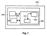
図1は、本発明の例示的な実施形態によるバッテリの複数のセルを制御する装置の概略図を示す。 FIG. 1 shows a schematic diagram of an apparatus for controlling a plurality of cells of a battery according to an exemplary embodiment of the present invention.
バッテリ100の複数のセル110、120、130、140、150を制御する装置200は、複数のセル制御ユニット214、224、234、244、254を有するバッテリ制御モジュール210を有し、各々のセル制御ユニットは、セルの1つに割り当てられ、各々のセル制御ユニットは、割り当てられたセルの充電バランスを変えるように構成され、各々のセル制御ユニットは、割り当てられたセルの少なくとも1つのセルパラメータを測定するように構成される。
The
バッテリ100は、複数のセル110、120、130、140、150及び装置200を有することができる、装置は、バッテリ100のハウジングに一体化されることができる。
The
装置200は更に、充電−放電サイクル中のバッテリセルの充電状態の好適レンジを規定するように構成される主制御モジュール220を有することができ、好適レンジは、フルレンジと比べて低減されたものであり、主制御モジュールは更に、充電−放電サイクルがフルレンジ内のフル充電状態を有して実施される選択されたセルの第1のグループと、充電−放電サイクルが好適レンジ内で実施される非選択セルの第2のグループと、を提供するように構成される。
The
主制御モジュール220は、第1の最小充電状態値よって、及び第1の最大値又はフル充電された充電状態の値によって、バッテリセルの充電状態のフルレンジを規定するように構成されることができる。
The
主制御モジュール220は、バッテリの任意の印加パワー要求が満たされることができ又はバッテリ容量の予め規定された値がバッテリ100によって提供されるように、フルレンジの第1の最小充電状態値を規定するように構成されることができる。
The
バッテリ容量は、バッテリ100が定格電圧で供給することができる充電量でありうる。容量は、例えばアンペア−時間(Ah)のような単位で測定されることができる。
The battery capacity may be a charge amount that the
主制御モジュール220は、第2の最小充電状態値と第2の最大充電状態値との間で、充電状態の制限されたレンジ又は好適レンジを規定するように構成されることができる。好適レンジの第2の最小充電状態値は、主制御モジュール220によって、フルレンジの第1の最小充電状態値と同じ又は対応する値に、又はより低い値に規定されることができる。好適レンジの第2の最大の充電状態値は、主制御モジュール220によって、フルレンジの第1の最小充電状態値より低いものであってもよい。
The
バッテリ100又はバッテリのセル110、120、130、140、150は、充電プロセスの間、主充電器300に直接に又は図1にて図示したように装置200を通じて間接的に、接続されることができる。放電プロセスの間、バッテリ100は、電気コンシューマ300に対応する同じ装置にパワーを供給することができる。
The
X線源500は、バッテリ100及び装置200を有する高電圧発生器400を有することができる。
The
図2は、本発明の例示的な実施形態によるバッテリの複数のセルを制御する方法の概略的なフローチャートを示す。 FIG. 2 shows a schematic flowchart of a method for controlling a plurality of cells of a battery according to an exemplary embodiment of the present invention.
方法は、ブロック図に関して視覚化されている。方法は、2つのステップS1及びS2、又は他のステップを有することができる。 The method is visualized with respect to the block diagram. The method can have two steps S1 and S2, or other steps.
方法の第1のステップとして、充電−放電サイクル中のバッテリセルの充電状態の好適レンジを規定すること(S1)が実施され、ここで、好適レンジは、フルレンジと比べて低減されたものである。 As a first step of the method, defining a preferred range of the state of charge of the battery cell during the charge-discharge cycle is implemented (S1), where the preferred range is reduced compared to the full range. .
方法の第2のステップとして、充電−放電サイクルがフルレンジ内のフル充電状態を有して実施される選択されたセルの第1のグループを提供すること(S2)、及び充電−放電サイクルが好適レンジ内で実施される非選択セルの第2のグループを提供することが、実施される。 As a second step of the method, providing a first group of selected cells where the charge-discharge cycle is performed with a full charge state within the full range (S2), and the charge-discharge cycle is preferred Providing a second group of unselected cells implemented in the range is performed.
本発明の例示的な実施形態によれば、これらのステップは、同時に実施されることができ、あるいは、複数の動作又はタスクに分割されることができ、あるいは反復的に繰り返されることができる。ステップの繰り返しは、カウント制御されるループによって、又は、条件制御されるループによって、再帰的に実現されることができる。 According to exemplary embodiments of the present invention, these steps can be performed simultaneously, can be divided into multiple operations or tasks, or can be repeated iteratively. The iteration of the steps can be realized recursively by a count controlled loop or by a condition controlled loop.
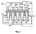
図3は、本発明の例示的な実施形態によるバッテリの複数のセルを制御する装置の概略図を示す。 FIG. 3 shows a schematic diagram of an apparatus for controlling a plurality of cells of a battery according to an exemplary embodiment of the present invention.
装置200は、バッテリ制御モジュール210及び主制御モジュール220を有することができる。バッテリ制御モジュール210は、複数のセル制御ユニット214、224、234、244、254を有することができる。1つのセル制御ユニット214は、1つのセル110に結合され、1つのセル110には、セル制御ユニット214が割り当てられる。セル110、120、130、140、150の各々は、セルハウジング112、122、132、142、152のうちの1つに組み込まれることができる。
The
本発明の別の例示的な実施形態において、セル制御ユニット214、224、234、244、254は、制御バス230を通じて主制御モジュール220に接続されることができ、セル制御ユニット214、224、234、244、254の割り当てられたセル110、120、130、140、150の充電又は放電要求に関して特定のコマンドを受け取る。
In another exemplary embodiment of the present invention,
本発明の別の例示的な実施形態において、主充電器300は、制御バス230を通じて主制御モジュール220に接続されることができ、バッテリ100の充電又は放電要求に関するコマンドを受け取る。
In another exemplary embodiment of the present invention, the
本発明の別の例示的な実施形態において、バッテリ100は、正端子101及び負端子102を有することができ、端子101、102を通じて、バッテリ100は、主充電器300に結合されることができる。
In another exemplary embodiment of the present invention, the
本発明の別の例示的な実施形態において、主制御モジュール220は、バッテリステータスシステム(例えばクーロン計数システム(「CCS」)を実現することができ、バッテリステータスシステムは、バッテリ100との間で電流フローを測定し、複数のセル制御ユニット214、224、234、244、254を使用し、及び時間にわたってセル110、120、130、140、150へ/からの電流フローを積分することによって、バッテリ100の容量を計算する。
In another exemplary embodiment of the present invention, the
本発明の別の例示的な実施形態において、適当なシステム上で上述の実施形態の1つに従う方法の方法ステップを実行するように適応されることによって特徴付けられるコンピュータプログラム又はコンピュータプログラム要素が提供される。 In another exemplary embodiment of the present invention, there is provided a computer program or computer program element characterized by being adapted to perform the method steps of the method according to one of the above embodiments on a suitable system. Is done.
従って、本発明の他の例示的な実施形態によれば、コンピュータプログラム要素は、本発明の一実施形態の一部でありうるコンピュータユニットに記憶されることができる。このコンピューティングユニットは、上述の方法のステップを実施するように又はその実施を誘導するように適応されることができる。 Thus, according to another exemplary embodiment of the present invention, computer program elements may be stored in a computer unit that may be part of one embodiment of the present invention. This computing unit can be adapted to perform the steps of the method described above or to guide its implementation.
更に、コンピューティングユニットは、上述した装置のコンポーネントを動作させるように適応されることができる。コンピューティングユニットは、ユーザの命令を自動的に動作させ及び/又は実行するように適応されることができる。コンピュータプログラムは、データプロセッサの作業メモリにロードされることができる。従って、データプロセッサは、本発明の方法を実施する能力が有することができる。 Furthermore, the computing unit can be adapted to operate the components of the apparatus described above. The computing unit may be adapted to automatically operate and / or execute user instructions. The computer program can be loaded into the working memory of the data processor. Thus, the data processor can have the ability to implement the method of the present invention.
本発明のこの例示的な実施形態は、最初から本発明を使用するコンピュータプログラムと、更新によって、既存のプログラムを本発明を使用するプログラムに変えるコンピュータプログラムとの両方をカバーする。 This exemplary embodiment of the present invention covers both a computer program that uses the present invention from the beginning and a computer program that, by updating, turns an existing program into a program that uses the present invention.
更に、コンピュータプログラム要素は、上述の方法の例示的な実施形態のプロシージャを果たすために必要なすべてのステップを提供することが可能でありうる。 Further, the computer program element may be able to provide all the steps necessary to perform the procedure of the exemplary embodiment of the method described above.
本発明の他の例示的な実施形態により、コンピュータ可読媒体に記憶されたコンピュータプログラム要素であって、上述のセクションによって記述されるコンピュータプログラム要素を有する該コンピュータ可読媒体(例えばCD−ROM)が提示される。 According to another exemplary embodiment of the present invention, a computer program element stored on a computer readable medium, the computer readable medium (e.g. CD-ROM) comprising the computer program element described by the above section being presented. Is done.
コンピュータプログラムは、他のハードウェアと共に又はその一部として供給される適切な媒体、例えば光学記憶媒体又は固体媒体に記憶され及び/又は配布されることができるが、他の形式で、例えばインターネット又は他のワイヤード若しくはワイヤレス通信システムを通じて配布されることもできる。 The computer program may be stored and / or distributed on any suitable medium supplied with or as part of other hardware, such as an optical storage medium or solid medium, but in other forms such as the Internet or It can also be distributed through other wired or wireless communication systems.
従って、コンピュータプログラムは、ワールドワイドウェブのようにネットワークを通じて提示されることができ、このようなネットワークからデータプロセッサの作業メモリにダウンロードされることができる。 Thus, the computer program can be presented over a network, such as the World Wide Web, and can be downloaded from such a network to the working memory of the data processor.
本発明の他の例示的な実施形態により、本発明の上述の実施形態のうちの1つに従う方法を実施するように構成されるコンピュータプログラム要素をダウンロードできるようにする媒体が提供される。 According to another exemplary embodiment of the present invention, there is provided a medium that enables a computer program element configured to perform a method according to one of the above-described embodiments of the present invention to be downloaded.
本発明の実施形態は、それぞれ異なる発明の主題に関して記述されていることに注意すべきである。特に、ある実施形態は、方法タイプの請求項に関して記述され、他の実施形態が、装置タイプの請求項に関して記述される。 It should be noted that the embodiments of the present invention are described with respect to different inventive subject matter. In particular, certain embodiments are described with respect to method type claims, and other embodiments are described with respect to device type claims.
しかしながら、当業者であれば、上述及び後述の説明から、他の場合が示されない限り、本発明の主題の1つのタイプに属する特徴の任意の組み合わせに加えて、異なる主題に関連する特徴の間の任意の組み合わせが、本願によって開示されていると考えられることが分かるであろう。しかしながら、すべての特徴は、特徴の単なる足し合わせより多くの相乗効果を提供するように組み合わせられることができる。 However, those skilled in the art will understand that, in addition to any combination of features belonging to one type of subject matter of the present invention, between features associated with different subjects, unless otherwise indicated from the foregoing and following description. It will be appreciated that any combination of is considered to be disclosed by the present application. However, all the features can be combined to provide more synergy than just adding the features.
本発明は、図面及び上述の説明において詳しく図示され記述されているが、このような図示及び記述は、制限的なものではなく、説明的又は例示的なものであると考えられることができる。本発明は、開示される実施形態に制限されない。開示された実施形態に対する他の変更は、図面、開示及び添付の請求項における検討から、本発明を実施する当業者によって理解され達成されることができる。 While the invention has been illustrated and described in detail in the drawings and foregoing description, such illustration and description are to be considered illustrative or exemplary rather than restrictive. The invention is not limited to the disclosed embodiments. Other modifications to the disclosed embodiments can be understood and attained by those skilled in the art, which practice the invention, from a study of the drawings, the disclosure, and the appended claims.
請求項において、「有する、含む(comprising)」という語は、他の構成要素又はステップを除外せず、不定冠詞「a」又は「an」は複数性を除外しない。単一のプロセッサ、コントローラ、又は他のユニットが、請求項に列挙されるいくつかのアイテムの機能を果たすことができる。特定の手段が相互に異なる従属請求項に列挙されているという単なる事実は、これらの手段の組み合わせが有利に使用されることができないことを示さない。請求項における参照符号は、請求項の範囲を制限するものとして解釈されるべきでない。 In the claims, the word “comprising” does not exclude other elements or steps, and the indefinite article “a” or “an” does not exclude a plurality. A single processor, controller, or other unit may fulfill the functions of several items recited in the claims. The mere fact that certain measures are recited in mutually different dependent claims does not indicate that a combination of these measured cannot be used to advantage. Any reference signs in the claims should not be construed as limiting the scope of the claims.
Claims (15)
複数のセル制御ユニットを有するバッテリ制御モジュールであって、各セル制御ユニットが、前記複数のセルの1つに割り当てられており、各セル制御ユニットが、割り当てられた当該1つのセルの充電状態レベルを変更し且つ当該1つのセルの少なくとも1つのセルパラメータを測定する、バッテリ制御モジュールと、
充電−放電サイクル中の前記バッテリのセルの充電状態の好適レンジを規定する主制御モジュールであって、前記好適レンジはフルレンジと比較して低減されたものであり、前記主制御モジュールは、前記複数のセルにおいて、1又は複数のセルの第1のグループ及び前記第1のグループの前記セルと異なるセルの第2のグループを提供し、前記第1のグループにおいて、前記フルレンジ内でのフル充電状態を有して前記充電−放電サイクルが実施され、前記第2のグループにおいて、前記充電−放電サイクルが前記好適レンジ内で実施されるよう、各セル制御ユニットを制御し、フル充電された前記第1のグループは前記第2のグループの充電状態レベルに対応する充電状態レベルに放電される、前記主制御モジュールと、
を有する装置。 A device for controlling a plurality of cells of a battery , wherein the plurality of cells of the battery are connected directly or indirectly to a main charger, the device comprising:
A battery control module having a plurality of cell control units, wherein each cell control unit is assigned to one of the plurality of cells, and each cell control unit is assigned to a charge state level of the assigned one cell. And a battery control module that measures at least one cell parameter of the one cell;
A main control module that prescribes a preferred range of charge states of the battery cells during a charge-discharge cycle, wherein the preferred range is reduced compared to a full range, wherein the main control module comprises the plurality of A first group of one or more cells and a second group of cells different from the cells of the first group, wherein the first group is fully charged within the full range. The second control unit controls each cell control unit so that the charge-discharge cycle is performed within the preferred range and is fully charged in the second group. The main control module, wherein one group is discharged to a charge state level corresponding to the charge state level of the second group;
Having a device.
充電−放電サイクル中の前記バッテリのセルの充電状態の好適レンジを規定するステップであって、前記好適レンジはフルレンジと比較して低減されたものである、ステップと、
前記複数のセルにおいて、1又は複数のセルの第1のグループ及び前記第1のグループの前記セルと異なるセルの第2のグループを提供するステップであって、前記第1のグループにおいて、前記充電−放電サイクルがフルレンジ内のフル充電状態を有して実施され、前記第2のグループにおいて、前記充電−放電サイクルが前記好適レンジ内で実施されるよう、各セル制御ユニットを制御し、フル充電された前記第1のグループは前記第2のグループの充電状態レベルに対応する充電状態レベルに放電される、ステップと、
を有する方法。 A method of controlling a plurality of cells of a battery , wherein the plurality of cells of the battery are connected directly or indirectly to a main charger, the method comprising:
Defining a preferred range of charge states of the cells of the battery during a charge-discharge cycle, the preferred range being reduced compared to a full range; and
Providing a first group of one or more cells and a second group of cells different from the cells of the first group in the plurality of cells, wherein the charging in the first group - discharge cycle is performed with a full charge in the full range, in the second group, the charge - so that discharge cycle is performed in the preferred range in controls each cell control unit, full charge The first group is discharged to a state of charge level corresponding to a state of charge level of the second group;
Having a method.
Applications Claiming Priority (3)
| Application Number | Priority Date | Filing Date | Title |
|---|---|---|---|
| EP14172889.9 | 2014-06-18 | ||
| EP14172889 | 2014-06-18 | ||
| PCT/EP2015/060827 WO2015193041A1 (en) | 2014-06-18 | 2015-05-18 | Device and method for controlling a plurality of cells of a battery |
Publications (2)
| Publication Number | Publication Date |
|---|---|
| JP2017511104A JP2017511104A (en) | 2017-04-13 |
| JP6300945B2 true JP6300945B2 (en) | 2018-03-28 |
Family
ID=50979560
Family Applications (1)
| Application Number | Title | Priority Date | Filing Date |
|---|---|---|---|
| JP2016555310A Expired - Fee Related JP6300945B2 (en) | 2014-06-18 | 2015-05-18 | Apparatus and method for controlling a plurality of cells of a battery |
Country Status (6)
| Country | Link |
|---|---|
| US (1) | US20170104350A1 (en) |
| EP (1) | EP3078073B1 (en) |
| JP (1) | JP6300945B2 (en) |
| CN (1) | CN105993094B (en) |
| ES (1) | ES2653513T3 (en) |
| WO (1) | WO2015193041A1 (en) |
Families Citing this family (16)
| Publication number | Priority date | Publication date | Assignee | Title |
|---|---|---|---|---|
| DK3417522T3 (en) | 2016-02-15 | 2023-03-20 | Pitt Ohio Express Llc | COMBINED WIND/SOLAR DRIVEN DC SYSTEM |
| US10403923B1 (en) | 2016-03-11 | 2019-09-03 | SimpliPhi Power, Incorporated | Battery having a folded architecture |
| CN106129457B (en) * | 2016-08-12 | 2019-02-12 | 淄博火炬能源有限责任公司 | Fork truck Li-ion batteries piles |
| CN106652630A (en) * | 2016-12-07 | 2017-05-10 | 行云新能科技(深圳)有限公司 | Electric automobile battery management simulation system |
| EP3600750B1 (en) * | 2017-03-17 | 2023-08-30 | Nelson Stud Welding, Inc. | Portable drawn arc stud welder including a lithium ferrophosphate battery |
| US10646192B2 (en) * | 2017-03-20 | 2020-05-12 | General Electric Company | Peak shave enabled computed tomography system with built-in uninterruptible power supply and stabilizer |
| EP3398818B1 (en) * | 2017-05-04 | 2022-07-06 | Volvo Car Corporation | Voltage supply unit, battery balancing method |
| EP3817947B1 (en) * | 2018-07-05 | 2023-02-15 | Volvo Truck Corporation | A method of controlling a battery system in a vehicle |
| KR20210037700A (en) | 2018-07-31 | 2021-04-06 | 시온 파워 코퍼레이션 | Multiplex Charge Discharge Battery Management System |
| CN112134315B (en) * | 2019-06-25 | 2023-07-14 | 比亚迪股份有限公司 | Control system and control method for gradient battery |
| US11056728B2 (en) | 2019-10-31 | 2021-07-06 | Sion Power Corporation | System and method for operating a rechargeable electrochemical cell or battery |
| US11424492B2 (en) | 2019-10-31 | 2022-08-23 | Sion Power Corporation | System and method for operating a rechargeable electrochemical cell or battery |
| TWI762961B (en) * | 2020-06-24 | 2022-05-01 | 倍米科技股份有限公司 | A system of battery pack balancing using a single charger and charging method |
| US20230327446A1 (en) * | 2022-04-08 | 2023-10-12 | Enphase Energy, Inc. | Integrated pcba design with fast connection-disconnection capabilities for cell to system design |
| DE102022116264A1 (en) | 2022-06-29 | 2024-01-04 | Webasto SE | Method for electrically connecting a set of battery packs in parallel, an electronic control device, a computer program, a computer-readable storage medium, a battery system and a motor vehicle |
| CN116961177B (en) * | 2023-07-20 | 2024-03-08 | 安徽大学 | Method for utilizing maximum available capacity of battery pack based on dispatching field algorithm |
Family Cites Families (45)
| Publication number | Priority date | Publication date | Assignee | Title |
|---|---|---|---|---|
| JP3229696B2 (en) * | 1993-02-25 | 2001-11-19 | 三洋電機株式会社 | How to charge the battery |
| JP3304777B2 (en) * | 1996-08-22 | 2002-07-22 | トヨタ自動車株式会社 | Electric vehicle |
| DE10015885A1 (en) * | 2000-03-30 | 2001-10-11 | Philips Corp Intellectual Pty | AC adapter or charger |
| JP4065232B2 (en) * | 2003-12-11 | 2008-03-19 | 三洋電機株式会社 | How to charge the battery |
| CN101278469B (en) * | 2005-10-05 | 2012-11-14 | 皇家飞利浦电子股份有限公司 | Driver circuit arrangement |
| JP4745879B2 (en) * | 2006-04-06 | 2011-08-10 | 日立ビークルエナジー株式会社 | Hybrid vehicle control system, hybrid vehicle control method, and vehicle storage battery control system |
| JP4413888B2 (en) * | 2006-06-13 | 2010-02-10 | 株式会社東芝 | Storage battery system, in-vehicle power supply system, vehicle, and method for charging storage battery system |
| US8222870B2 (en) * | 2007-03-07 | 2012-07-17 | O2Micro, Inc | Battery management systems with adjustable charging current |
| JP5109619B2 (en) * | 2007-11-21 | 2012-12-26 | トヨタ自動車株式会社 | Battery pack system and charge / discharge control method |
| US8330413B2 (en) * | 2008-06-12 | 2012-12-11 | Honeywell International Inc. | Method and system for determining and charging Li-ion battery in an integrated power system |
| GB2462467B (en) * | 2008-08-08 | 2013-03-13 | P G Drives Technology Ltd | A cell management system |
| KR101023735B1 (en) * | 2008-10-07 | 2011-03-25 | 주식회사 포스콤 | X-ray device with baterry power |
| JP5656415B2 (en) * | 2009-03-26 | 2015-01-21 | プライムアースEvエナジー株式会社 | Secondary battery state determination device and control device |
| WO2010140235A1 (en) * | 2009-06-03 | 2010-12-09 | 三菱重工業株式会社 | Grouped cells state of charge calculation device, grouped cells state of charge calculation method, program, and grouped cells soc display device |
| JP5593849B2 (en) * | 2009-06-12 | 2014-09-24 | 日産自動車株式会社 | Battery monitoring device |
| EP2272722B1 (en) * | 2009-07-01 | 2015-04-08 | Denso Corporation | Power source apparatus for vehicle |
| JP2011041452A (en) * | 2009-07-17 | 2011-02-24 | Toshiba Corp | Assembled battery unit and vehicle |
| US8629657B2 (en) * | 2009-12-31 | 2014-01-14 | Tesla Motors, Inc. | State of charge range |
| WO2011085317A2 (en) * | 2010-01-11 | 2011-07-14 | A123 Systems, Inc. | System and method for monitoring and balancing voltage of individual battery cells within a battery pack |
| US8564246B2 (en) * | 2010-03-30 | 2013-10-22 | Grrreen, Inc. | Battery charging system and method |
| US8541979B2 (en) * | 2010-06-22 | 2013-09-24 | A123 Systems, Inc. | System and method for balancing voltage of individual battery cells within a battery pack |
| US8190320B2 (en) * | 2010-08-10 | 2012-05-29 | Tesla Motors, Inc. | Efficient dual source battery pack system for an electric vehicle |
| DE102010039913A1 (en) * | 2010-08-30 | 2012-03-01 | Sb Limotive Company Ltd. | A method for balancing states of charge of a battery with a plurality of battery cells and a corresponding battery management system and a battery |
| JP5605436B2 (en) * | 2010-12-20 | 2014-10-15 | トヨタ自動車株式会社 | Electric vehicle and control method thereof |
| WO2012119297A1 (en) * | 2011-03-05 | 2012-09-13 | Global Storage Group Llc | Electrical energy storage unit |
| US9450426B2 (en) * | 2011-03-07 | 2016-09-20 | A123 Systems Llc | Method for opportunistically balancing charge between battery cells |
| KR101367875B1 (en) * | 2011-03-21 | 2014-02-26 | 주식회사 엘지화학 | Apparatus for controlling connection of battery pack |
| US9196930B2 (en) * | 2011-03-24 | 2015-11-24 | Ford Global Technologies, Llc | Vehicle battery cell with integral control circuit |
| JP5727868B2 (en) * | 2011-05-30 | 2015-06-03 | 旭化成株式会社 | Power storage module and charge control method |
| EP2752956A4 (en) * | 2011-09-02 | 2015-09-30 | Nec Corp | Cell control system, cell control device, cell control method, and recording medium |
| CN103765721B (en) * | 2011-09-08 | 2016-04-06 | 日立汽车系统株式会社 | Battery system monitoring arrangement |
| JP6106991B2 (en) * | 2011-09-09 | 2017-04-05 | 株式会社Gsユアサ | State management device and method for equalizing storage elements |
| US20140239914A1 (en) * | 2011-10-06 | 2014-08-28 | Hitachi Vehicle Energy, Ltd. | Battery controller |
| CN103918120B (en) * | 2011-10-11 | 2016-07-06 | 新神户电机株式会社 | Lead accumulator system |
| FR2983653B1 (en) * | 2011-12-06 | 2014-01-17 | Renault Sa | METHOD FOR MANAGING AN ALTERNATOR ASSOCIATED WITH AT LEAST ONE BATTERY OF POWER SUPPLY AND DRIVEN BY A THERMAL MOTOR |
| JP5842768B2 (en) * | 2012-08-22 | 2016-01-13 | 富士通株式会社 | Deduplication apparatus, deduplication method, and deduplication program |
| US20140266061A1 (en) * | 2013-03-13 | 2014-09-18 | Manitoba Hydro International Ltd. | Heterogeneous Energy Storage System and Associated Methods |
| US9236749B2 (en) * | 2013-04-08 | 2016-01-12 | GM Global Technology Operations LLC | Vehicle battery system balancing systems and methods |
| US20140358343A1 (en) * | 2013-05-28 | 2014-12-04 | Raymond Louis Chastang, JR. | Vehicle tire frictional drive rotational power and energy source |
| EP3020116B1 (en) * | 2013-07-11 | 2017-04-26 | Philips Lighting Holding B.V. | Capacitive powering system with increased efficiency |
| EP3025430A1 (en) * | 2013-07-26 | 2016-06-01 | Koninklijke Philips N.V. | Contactless pick-up of a signal |
| JP6119516B2 (en) * | 2013-09-02 | 2017-04-26 | ソニー株式会社 | Battery pack and electric vehicle |
| US9612288B2 (en) * | 2014-01-31 | 2017-04-04 | Analog Devices Global | Voltage-based fuel gauge on battery capacity |
| JP6172008B2 (en) * | 2014-03-24 | 2017-08-02 | トヨタ自動車株式会社 | Hybrid vehicle |
| US20160043580A1 (en) * | 2014-08-07 | 2016-02-11 | General Electric Company | System and method for reducing current variability between multiple energy storage devices |
-
2015
- 2015-05-18 CN CN201580008428.3A patent/CN105993094B/en not_active Expired - Fee Related
- 2015-05-18 JP JP2016555310A patent/JP6300945B2/en not_active Expired - Fee Related
- 2015-05-18 ES ES15725273.5T patent/ES2653513T3/en active Active
- 2015-05-18 US US15/112,451 patent/US20170104350A1/en not_active Abandoned
- 2015-05-18 WO PCT/EP2015/060827 patent/WO2015193041A1/en active Application Filing
- 2015-05-18 EP EP15725273.5A patent/EP3078073B1/en not_active Not-in-force
Also Published As
| Publication number | Publication date |
|---|---|
| EP3078073A1 (en) | 2016-10-12 |
| CN105993094A (en) | 2016-10-05 |
| WO2015193041A1 (en) | 2015-12-23 |
| EP3078073B1 (en) | 2017-10-04 |
| ES2653513T3 (en) | 2018-02-07 |
| CN105993094B (en) | 2017-10-24 |
| US20170104350A1 (en) | 2017-04-13 |
| JP2017511104A (en) | 2017-04-13 |
Similar Documents
| Publication | Publication Date | Title |
|---|---|---|
| JP6300945B2 (en) | Apparatus and method for controlling a plurality of cells of a battery | |
| JP4405558B2 (en) | Battery smoothing system and method using state of charge | |
| KR102634816B1 (en) | An battery monitoring apparatus detecting charge balance of a battery and a method thereof | |
| EP2002525B1 (en) | Battery charge indication methods, battery charge monitoring devices, rechargeable batteries and articles of manufacture | |
| CN102097835B (en) | Battery pack | |
| EP2553483B1 (en) | Monitoring state of charge of a battery system | |
| JP2015073429A (en) | Method for detecting cell state-of-charge and state-of-discharge divergence of series string of batteries or capacitors | |
| US9018912B2 (en) | System and method for managing parallel-connected battery cells | |
| US10910847B2 (en) | Active cell balancing in batteries using switch mode dividers | |
| RU2600313C1 (en) | Device for controlling battery, energy accumulating device, energy accumulating method and program | |
| US20190157896A1 (en) | Battery management apparatus and method for protecting a lithium iron phosphate cell from over-voltage using the same | |
| JP2016023968A (en) | Battery state detection device, secondary battery system, battery state detection program, and battery state detection method | |
| US20160197506A1 (en) | Battery pack | |
| JP6848475B2 (en) | Storage control device, server, storage control method and program | |
| CN102343831A (en) | System and method for rebalancing a vehicle battery | |
| JP7293569B2 (en) | Battery management device and method | |
| JP2003068369A (en) | Detecting method of total capacity of secondary battery and detector of total capacity | |
| US11796599B2 (en) | Battery diagnosis apparatus, battery diagnosis method and energy storage system | |
| JP6881414B2 (en) | Battery management system, battery management method and battery management program | |
| KR20230017598A (en) | Method for charging a plurality of battery cells and control device for performing the method | |
| KR101342529B1 (en) | Energy storage system controller, method and computer readable recording medium thereof | |
| JP2024513368A (en) | Device and method for managing battery open circuit voltage (OCV)-state of charge (SOC) profile | |
| Aalto | Battery Cell Modeling for Battery Management System | |
| JP2022089830A (en) | Monitoring system for series-connected battery cells | |
| WO2016152100A1 (en) | Storage battery management device, control device, storage battery module, and storage battery management method |
Legal Events
| Date | Code | Title | Description |
|---|---|---|---|
| A975 | Report on accelerated examination |
Free format text: JAPANESE INTERMEDIATE CODE: A971005 Effective date: 20170207 |
|
| A131 | Notification of reasons for refusal |
Free format text: JAPANESE INTERMEDIATE CODE: A131 Effective date: 20170214 |
|
| RD04 | Notification of resignation of power of attorney |
Free format text: JAPANESE INTERMEDIATE CODE: A7424 Effective date: 20170214 |
|
| A521 | Request for written amendment filed |
Free format text: JAPANESE INTERMEDIATE CODE: A523 Effective date: 20170512 |
|
| A131 | Notification of reasons for refusal |
Free format text: JAPANESE INTERMEDIATE CODE: A131 Effective date: 20170613 |
|
| A521 | Request for written amendment filed |
Free format text: JAPANESE INTERMEDIATE CODE: A523 Effective date: 20170912 |
|
| A02 | Decision of refusal |
Free format text: JAPANESE INTERMEDIATE CODE: A02 Effective date: 20170926 |
|
| A521 | Request for written amendment filed |
Free format text: JAPANESE INTERMEDIATE CODE: A523 Effective date: 20180125 |
|
| A911 | Transfer to examiner for re-examination before appeal (zenchi) |
Free format text: JAPANESE INTERMEDIATE CODE: A911 Effective date: 20180202 |
|
| TRDD | Decision of grant or rejection written | ||
| A01 | Written decision to grant a patent or to grant a registration (utility model) |
Free format text: JAPANESE INTERMEDIATE CODE: A01 Effective date: 20180222 |
|
| A61 | First payment of annual fees (during grant procedure) |
Free format text: JAPANESE INTERMEDIATE CODE: A61 Effective date: 20180227 |
|
| R150 | Certificate of patent or registration of utility model |
Ref document number: 6300945 Country of ref document: JP Free format text: JAPANESE INTERMEDIATE CODE: R150 |
|
| R250 | Receipt of annual fees |
Free format text: JAPANESE INTERMEDIATE CODE: R250 |
|
| LAPS | Cancellation because of no payment of annual fees |