KR20200069964A - Cooling system for refrigerated vehicle - Google Patents
Cooling system for refrigerated vehicle Download PDFInfo
- Publication number
- KR20200069964A KR20200069964A KR1020180157584A KR20180157584A KR20200069964A KR 20200069964 A KR20200069964 A KR 20200069964A KR 1020180157584 A KR1020180157584 A KR 1020180157584A KR 20180157584 A KR20180157584 A KR 20180157584A KR 20200069964 A KR20200069964 A KR 20200069964A
- Authority
- KR
- South Korea
- Prior art keywords
- power
- cooling
- vehicle
- battery
- refrigeration
- Prior art date
- Legal status (The legal status is an assumption and is not a legal conclusion. Google has not performed a legal analysis and makes no representation as to the accuracy of the status listed.)
- Granted
Links
Images


Classifications
-
- B—PERFORMING OPERATIONS; TRANSPORTING
- B60—VEHICLES IN GENERAL
- B60H—ARRANGEMENTS OF HEATING, COOLING, VENTILATING OR OTHER AIR-TREATING DEVICES SPECIALLY ADAPTED FOR PASSENGER OR GOODS SPACES OF VEHICLES
- B60H1/00—Heating, cooling or ventilating devices
- B60H1/32—Cooling devices
- B60H1/3204—Cooling devices using compression
- B60H1/3226—Self-contained devices, i.e. including own drive motor
-
- B—PERFORMING OPERATIONS; TRANSPORTING
- B60—VEHICLES IN GENERAL
- B60H—ARRANGEMENTS OF HEATING, COOLING, VENTILATING OR OTHER AIR-TREATING DEVICES SPECIALLY ADAPTED FOR PASSENGER OR GOODS SPACES OF VEHICLES
- B60H1/00—Heating, cooling or ventilating devices
- B60H1/32—Cooling devices
- B60H1/3204—Cooling devices using compression
- B60H1/3232—Cooling devices using compression particularly adapted for load transporting vehicles
-
- B—PERFORMING OPERATIONS; TRANSPORTING
- B60—VEHICLES IN GENERAL
- B60H—ARRANGEMENTS OF HEATING, COOLING, VENTILATING OR OTHER AIR-TREATING DEVICES SPECIALLY ADAPTED FOR PASSENGER OR GOODS SPACES OF VEHICLES
- B60H1/00—Heating, cooling or ventilating devices
- B60H1/32—Cooling devices
- B60H1/3204—Cooling devices using compression
- B60H1/3205—Control means therefor
-
- B—PERFORMING OPERATIONS; TRANSPORTING
- B60—VEHICLES IN GENERAL
- B60P—VEHICLES ADAPTED FOR LOAD TRANSPORTATION OR TO TRANSPORT, TO CARRY, OR TO COMPRISE SPECIAL LOADS OR OBJECTS
- B60P3/00—Vehicles adapted to transport, to carry or to comprise special loads or objects
- B60P3/20—Refrigerated goods vehicles
-
- H—ELECTRICITY
- H02—GENERATION; CONVERSION OR DISTRIBUTION OF ELECTRIC POWER
- H02J—ELECTRIC POWER NETWORKS; CIRCUIT ARRANGEMENTS OR SYSTEMS FOR SUPPLYING OR DISTRIBUTING ELECTRIC POWER; SYSTEMS FOR STORING ELECTRIC ENERGY
- H02J7/00—Circuit arrangements for charging or discharging batteries or for supplying loads from batteries
- H02J7/02—Circuit arrangements for charging or discharging batteries or for supplying loads from batteries for charging batteries from AC mains by converters
-
- B—PERFORMING OPERATIONS; TRANSPORTING
- B60—VEHICLES IN GENERAL
- B60H—ARRANGEMENTS OF HEATING, COOLING, VENTILATING OR OTHER AIR-TREATING DEVICES SPECIALLY ADAPTED FOR PASSENGER OR GOODS SPACES OF VEHICLES
- B60H1/00—Heating, cooling or ventilating devices
- B60H1/32—Cooling devices
- B60H2001/3236—Cooling devices information from a variable is obtained
- B60H2001/3266—Cooling devices information from a variable is obtained related to the operation of the vehicle
-
- B—PERFORMING OPERATIONS; TRANSPORTING
- B60—VEHICLES IN GENERAL
- B60H—ARRANGEMENTS OF HEATING, COOLING, VENTILATING OR OTHER AIR-TREATING DEVICES SPECIALLY ADAPTED FOR PASSENGER OR GOODS SPACES OF VEHICLES
- B60H1/00—Heating, cooling or ventilating devices
- B60H1/32—Cooling devices
- B60H2001/3286—Constructional features
- B60H2001/3292—Compressor drive is electric only
Landscapes
- Engineering & Computer Science (AREA)
- Physics & Mathematics (AREA)
- Thermal Sciences (AREA)
- Mechanical Engineering (AREA)
- Health & Medical Sciences (AREA)
- Public Health (AREA)
- Transportation (AREA)
- Power Engineering (AREA)
- Devices That Are Associated With Refrigeration Equipment (AREA)
Abstract
본 발명에 따른 냉장/냉동 탑차의 냉각 시스템은, 차량용 엔진, 발전기, 차량용 배터리, 상기 차량용 배터리에 비해 상대적으로 고전압으로 작동되며, 상기 냉장/냉동 탑차와는 별도의 외부 전원으로부터 공급된 전기 에너지를 저장하기 위한 냉각용 배터리 및, 직류 모터가 구비된 전동 압축기, 응축기, 팽창밸브 및 증발기를 포함하여 냉각 사이클을 이루는 적어도 하나의 냉각 유닛을 포함하여 구성되며, 통상적인 상황에서는 상기 발전기의 전력이 상기 전동 압축기에 인가되지 않도록 전기적으로 차단됨과 동시에, 주행 모드에서는, 상기 냉각용 배터리 전원은 상기 전동 압축기 구동 전원으로만 사용되며, 주차 모드에서는, 상기 냉각용 배터리 전원은 상기 전동 압축기를 포함한 상기 냉각 유닛 전력 부하 전체의 구동 전원으로 사용되며, 대기모드에서는 상기 외부전원이 상기 냉각 유닛의 전력 부하 전체의 구동 전원으로 사용됨과 동시에 상기 냉각용 배터리에 충전 전력을 제공하도록 구성되어, 차량 운행을 위한 엔진 동력과는 완전히 무관한 동력원으로부터 냉각 유닛을 구동시키므로, 엔진 효율 저하가 발생하지 않고 RPM 변화 등 운행 상태에 따른 냉각 효율의 영향도 받지 않는다.The cooling system of the refrigerated/frozen truck according to the present invention is operated at a relatively high voltage compared to a vehicle engine, a generator, a vehicle battery, and the vehicle battery, and uses electric energy supplied from an external power source separate from the refrigerated/frozen truck. It comprises a cooling battery for storing and at least one cooling unit that forms a cooling cycle, including an electric compressor equipped with a DC motor, a condenser, an expansion valve, and an evaporator, and in normal circumstances, the power of the generator is At the same time as being electrically cut off from being applied to the electric compressor, in the driving mode, the cooling battery power is used only as the electric compressor driving power, and in the parking mode, the cooling battery power is the cooling unit including the electric compressor. It is used as the driving power for the entire power load, and in standby mode, the external power is used as the driving power for the entire power load of the cooling unit and is configured to provide charging power to the cooling battery, and the engine power for vehicle operation Since the unit drives the cooling unit from a completely unrelated power source, engine efficiency does not decrease and cooling efficiency according to operating conditions such as RPM changes is not affected.
Description
본 발명은 냉장/냉동 탑차용 냉각 시스템에 관한 것으로, 보다 상세하게는, 냉각 사이클이 적용된 냉각 유닛 방식의 냉각 시스템에 있어서, 압축기의 작동 동력을 전동 모터로서 적용한 경우에 최적화된 냉장/냉동 탑차용 냉각 시스템에 관한 것이다.The present invention relates to a cooling system for a refrigeration/refrigeration tower vehicle, and more particularly, in a cooling unit type cooling system to which a cooling cycle is applied, for an optimized refrigeration/refrigeration vehicle when the operating power of the compressor is applied as an electric motor. It relates to a cooling system.
냉장 탑차 또는 냉동 탑차라고도 불리는 냉각용 특장차에는, 운전 객실 이외에, 냉각 전용 공간인 탑 또는 고(庫)라고도 불리는 격실 형태의 공간이 별도로 설치된다.In the cooling special vehicle, also called a refrigerated top vehicle or a refrigerated top vehicle, in addition to the driving cabin, a space in the form of a compartment, also called a tower or high, which is a space dedicated to cooling, is separately provided.
해당 격실은 농, 축, 수산물이나, 화훼 그 밖의 신선도를 유지하여야 하는 물류의 보관 및 운송을 위해 사용되기 때문에, 효율적이고 적절한 냉각 기능을 필수적으로 구비하여야 한다.Since this compartment is used for storage and transportation of agricultural, livestock, aquatic products, flowers, and other logistics that must maintain freshness, efficient and appropriate cooling functions must be provided.
이러한 냉각 기능을 구비한 냉장/냉동 탑차로서는 크게 축냉 물질을 사용하는 축냉 방식 냉장/냉동 탑차와, 압축기를 포함한 냉각 유닛이 냉각 사이클을 구성하는 냉각 사이클 방식 냉장/냉동 탑차로 구분된다.The refrigerated/frozen wagon equipped with such a cooling function is largely divided into a refrigerated refrigerated/frozen wagon that uses a refrigerated material and a cooling cycle refrigerated/frozen wagon that a cooling unit including a compressor constitutes a cooling cycle.
축냉 방식의 경우, 운행 중 자동차에 구비된 동력원을 사용하지 않기 때문에 냉각 사이클 방식에 비해 차량의 운행 상태에 영향받지 않는 냉각 환경의 조성이 가능하다는 장점이 있으나, 핵심이 되는 부품인 축냉판의 무게가 무거워 운행 효율을 떨어뜨리는 점, 냉각판이 잠열을 흡수하여 상변화를 일으키는 시점에서는 더 이상 냉각 기능이 불가능하므로, 물류 보관/이동 가능 시간이 한정적이고 단속적인 점, 물류 보관/이동 중 축냉판이 냉각 성능을 유지할 수 있도록 하기 위해 물류 보관, 이동 이외의 시간에는 축냉 물질의 상변화를 일으켜 놓아야 하는데, 이때 탑차 내부의 온도를 영하 30도 이하까지 낮추는 과정에 상당한 에너지 및 시간이 소모되는 점 등의 단점이 있다.In the case of the axial cooling method, since it does not use a power source provided in the vehicle during operation, it has the advantage of being able to create a cooling environment that is not affected by the driving state of the vehicle compared to the cooling cycle method. Because it is heavy, the operation efficiency is reduced, and since the cooling plate absorbs latent heat and causes a phase change, the cooling function is no longer possible, so the time limit for logistics storage/movement is limited and intermittent. In order to maintain performance, it is necessary to cause a phase change of the refrigerated material during the time other than storage and transportation, and disadvantages such as significant energy and time are consumed in the process of lowering the temperature inside the truck to below 30 degrees below zero. There is this.
따라서, 장시간 지속적인 냉각 기능의 유지가 가능하고(동력만 제공된다면), 요구되는 바에 따라 냉각 정도의 조절이 용이하며, 자동차 운행 과정에서 엔진에서 발생하는 기계적인 동력이나 전력 등을 동력원으로 사용하여 냉각 기능을 수행할 수 있는 냉각 사이클 방식 냉장/냉동 탑차 역시 폭넓게 사용되고 있다.Therefore, it is possible to maintain a continuous cooling function for a long time (if only power is provided), and it is easy to adjust the degree of cooling as required, and cooling is performed by using mechanical power or power generated by the engine as a power source in the process of driving the vehicle. Refrigeration/refrigeration trucks that can perform functions are also widely used.
이러한 방식의 대표적인 구성으로, 냉각 사이클을 구성하는 부품 중 가장 높은 동력을 필요로 하는 압축기의 동력을, 차량 운행용 엔진의 동력으로부터 동축 연결하여 사용하는 엔진 동축 압축기 구동 방식 냉각 유닛이 있는데, 기왕의 자동차 동력을 활용한다는 점에서 효율적이나, 엔진의 동력을 나눠 쓰는 방식이므로 차량 출력 저하로 연료 소비가 증가 되는 점, 차량운행 시 엔진의 RPM 변화에 따라 냉방 성능이 급하게 변하는 현상이 발생할 수 있는 점, 냉동기 성능이 차량의 연비와 직접 관련되어 연료 소모량을 증가시켜 이산화탄소 배출량이 증가하므로, 환경 오염의 원인이 될 수 있는 점, 통상 소모품인 벨트를 구동력을 전달하는 수단으로 사용하여 벨트 손상으로 인한 부품 교체시기가 짧고, 에너지 낭비, 소음문제 등 발생한다는 점 등의 단점이 있다.As a typical configuration of this method, there is an engine coaxial compressor driving method cooling unit that uses the power of a compressor that needs the highest power among components constituting a cooling cycle coaxially from the power of an engine for driving a vehicle. It is efficient in that it utilizes automobile power, but it is a method of sharing the power of the engine, so fuel consumption increases due to a decrease in vehicle output, and when the vehicle is running, the cooling performance may change rapidly due to changes in engine RPM. Since the performance of the freezer is directly related to the fuel efficiency of the vehicle, the amount of carbon dioxide emissions is increased by increasing the consumption of fuel, which can cause environmental pollution.Replace parts due to belt damage by using the belt, which is usually a consumable, as a means to transmit driving power. There are shortcomings such as short time, energy waste and noise problems.
이를 보완하는 또 다른 냉각 사이클 방식으로, 이른바 서브 엔진 타입의 냉장/냉동 탑차가 사용되기도 한다.As another cooling cycle method to compensate for this, a so-called sub-engine type refrigeration/refrigeration truck is also used.
본 방식은, 차량 운행에 사용되는 엔진에 영향을 미치지 않기 위해 별도의 엔진을 이용하여 차량과는 독립적 구동 냉각 유닛을 설치하는 방식으로, 당연히 차량의 운행 출력 저하나 RPM 변화에 따른 냉각 성능의 변동이 발생하지 않는다는 장점이 있으나, 보조 압축기 구동 동력원 설치로 차량의 총중량 증가 및 공간의 활용도 저하에 따라 1~2톤 급의 소형 탑차에는 적합하지 않고 대형 차량(예를 들어 25톤급)에나 적용이 적합하다는 한계를 가지고 있다.This method is a method of installing an independent driving cooling unit from a vehicle by using a separate engine in order not to affect the engine used for driving the vehicle. Of course, the cooling performance fluctuates due to a decrease in the driving output of the vehicle or a change in RPM. This has the advantage that it does not occur, but it is not suitable for small to medium-sized vehicles of 1 to 2 tons, but suitable for large vehicles (e.g., 25 tons) due to the increase in the total weight of the vehicle and the reduced utilization of space due to the installation of an auxiliary compressor-driven power source. Has a limit.
따라서, 비교적 소형의 전동 모터를 이용하여 압축기를 구동하고 그 동력을 차량용 발전기나 차량용 배터리 등으로부터 공급받기 위한 형태의 전동 모터 압축기를 구비한 냉각 유닛 방식이 제안되어 왔다.Accordingly, a cooling unit method having a motor-driven compressor in a form for driving a compressor using a relatively small electric motor and receiving its power from a vehicle generator or a vehicle battery has been proposed.
이러한 예로, 일본 특허 출원 제1998-113332호에는, 모터를 동력원으로 하는 전동 압축기를 구비하고, 전원을 발전기, 상용전원 및 배터리를 활용하여 이 중 가장 높은 전압을 전원으로 사용하도록 하는 탑차용 냉각 사이클 시스템이 개시된 바 있으나, 이 역시 엔진 발전기의 전력을 냉각 유닛이 나눠쓰는 방식으로써, 통상의 차량용 전력 부하를 위한 배터리 전원을 전동 모터의 동력원으로도 사용한다는 점에서, 충분하고 지속 가능한 냉각 성능을 담보하기 어렵고, 엔진 성능에 직접적 영향을 줄 수밖에 없다는 단점이 여전히 존재한다.For this example, Japanese Patent Application No. 1998-113332 includes an electric compressor using a motor as a power source, and a cooling cycle for a tower vehicle using power as a generator, commercial power, and a battery to use the highest voltage among them as a power source. Although the system has been disclosed, this also ensures sufficient and sustainable cooling performance in that the cooling power of the engine generator is shared, and battery power for a normal vehicle power load is also used as a power source for the electric motor. There are still drawbacks that are difficult to do and have a direct impact on engine performance.
또한, 미국 특허 출원 제14/009586호에는, 발전기와 배터리의 두 종류의 동력원과 이들로부터 전력을 공급받는 다양한 전기 부하들간의 연결을 운행 상태에 따라 모드별로 적절하게 변경해가는 방식의 내용이 개시되고는 있으나, 앞서 설명한 특허에서와 마찬가지로 여전히 엔진에 직결된 발전기 및 배터리로부터 전력을 공급받도록 구성되어 있어, 효율적인 전원 관리에도 불구하고 차량 운행의 상태에 따라 냉각 성능의 균일성, 지속성을 담보하기 어려울 뿐만 아니라, 엔진 성능에 부담을 줄 수밖에 없다는 점을 해결하기 어렵다.In addition, U.S. Patent Application No. 14/009586 discloses a method of appropriately changing the connection between two types of power sources, such as a generator and a battery, and various electric loads that are supplied with electric power, according to a driving state, according to a mode. However, as in the patent described above, it is still configured to receive power from the generator and the battery directly connected to the engine, so it is difficult to guarantee uniformity and persistence of cooling performance depending on the state of vehicle operation despite efficient power management. No, it is difficult to solve the fact that it has no choice but to burden the engine performance.
상기한 종래 기술의 문제점을 극복하기 위하여, 본 발명에 따른 냉장/냉동 탑차의 냉각 시스템은, 차량 운행용 엔진에 영향을 미치지 않아 엔진 효율을 최대한으로 유지하면서도, 효율적이고 지속적인 고 내 냉각이 가능하도록 하는 냉장/냉동 탑차의 고 내용 냉각 시스템을 제공하는 것을 목적으로 한다.In order to overcome the above-mentioned problems of the prior art, the cooling system of the refrigeration/freezer tower vehicle according to the present invention does not affect the engine for driving the vehicle, while maintaining the engine efficiency to the maximum, enabling efficient and continuous high-internal cooling. It is an object of the present invention to provide a high-content cooling system for refrigeration/freezing tower vehicles.
본 발명의 또다른 목적은, 냉각 사이클의 주된 동력으로 전력을 사용하는 경우, 제한적일 수밖에 없는 전력 공급 환경에서도 한정된 전력을 최대한 효율적으로 사용할 수 있는, 배터리 전원에 최적화된 냉각 사이클을 구비한 냉장/냉동 탑차의 고 내용 냉각 시스템을 제공하는 것이다.Another object of the present invention, when using power as the main power of the cooling cycle, refrigeration / refrigeration with a cooling cycle optimized for battery power that can use the limited power as efficiently as possible even in a limited power supply environment It is to provide a high content cooling system of a top car.
본 발명의 또다른 목적은, 냉각 사이클을 위한 별도 전력원의 장시간 사용으로 냉각 시스템의 구동이 어려워지는 비상 상황에서도, 안정적인 외부 전력 수급 때까지 비상 전원을 활용할 수 있는 대비적 구성까지 완비한, 냉각 사이클을 구비한 냉장/냉동 탑차의 고 내용 냉각 시스템을 제공하는 것이다.Another object of the present invention, even in an emergency situation in which the cooling system is difficult to drive due to long-time use of a separate power source for a cooling cycle, is equipped with a ready configuration that can utilize emergency power until stable external power is supplied. It is to provide a high-content cooling system for a refrigerated/frozen truck equipped with a cycle.
본 발명이 이루고자 하는 기술적 과제들은 이상에서 언급한 기술적 과제들로제한되지 않으며, 언급되지 않은 또 다른 기술적 과제들은 아래의 기재로부터 본 발명이 속하는 기술 분야에서 통상의 지식을 가진 자에게 명확하게 이해될 수 있을 것이다.The technical problems to be achieved by the present invention are not limited to the technical problems mentioned above, and other technical problems that are not mentioned will be clearly understood by those skilled in the art from the following description. Will be able to.
전술한 목적을 달성하기 위하여, 본 발명에 따른 냉장/냉동 탑차의 냉각 시스템은, 압축기, 응축기, 팽창밸브, 증발기를 포함하여 구성되는 냉장/냉동 탑차의 고 내용 냉각 시스템에 있어서, 차량용 엔진, 상기 차량용 엔진으로부터 발생된 동력을 전기 에너지로 변환하는 발전기, 상기 발전기로부터의 전기 에너지를 저장하기 위한 차량용 배터리, 상기 차량용 배터리에 비해 상대적으로 고전압으로 작동되며, 상기 냉장/냉동 탑차와는 별도의 외부 전원으로부터 공급된 전기 에너지를 저장하기 위한 냉각용 배터리 및, 직류 모터가 구비된 전동 압축기, 응축기, 팽창밸브 및 증발기를 포함하여 냉각 사이클을 이루는 적어도 하나의 냉각 유닛을 포함하여 구성되며, 통상적인 상황에서는 상기 발전기의 전력이 상기 전동 압축기에 인가되지 않도록 전기적으로 차단됨과 동시에, 상기 차량용 엔진이 작동하여 상기 발전기로부터 전력이 발생되는 주행 모드에서는, 상기 냉각용 배터리 전원은 상기 전동 압축기 구동 전원으로만 사용되며, 상기 차량용 엔진은 작동하지 않으나 상기 외부전원에는 연결되지 않은 주차 모드에서는, 상기 냉각용 배터리 전원은 상기 전동 압축기를 포함한 상기 냉각 유닛 전력 부하 전체의 구동 전원으로 사용되며, 상기 외부전원이 연결된 대기모드에서는 상기 외부전원이 상기 냉각 유닛의 전력 부하 전체의 구동 전원으로 사용됨과 동시에 상기 냉각용 배터리에 충전 전력을 제공하도록 구성된다.In order to achieve the above object, the cooling system of the refrigeration/refrigeration tower vehicle according to the present invention includes a compressor, a condenser, an expansion valve, and a high-content cooling system of a refrigeration/refrigeration tower vehicle comprising an evaporator, a vehicle engine, the A generator that converts power generated from a vehicle engine into electrical energy, a vehicle battery for storing electrical energy from the generator, and is operated at a relatively high voltage compared to the vehicle battery, and an external power source separate from the refrigerated/frozen tower car It comprises a cooling battery for storing the electric energy supplied from, and at least one cooling unit that forms a cooling cycle including an electric compressor, a condenser, an expansion valve, and an evaporator equipped with a DC motor, and in a normal situation, In the driving mode in which the power of the generator is electrically cut off so as not to be applied to the electric compressor, and the vehicle engine is operated to generate electric power from the generator, the battery power for cooling is used only as the driving power of the electric compressor. In the parking mode in which the vehicle engine is not operated but is not connected to the external power, the cooling battery power is used as a driving power for the entire power load of the cooling unit including the electric compressor, and the standby mode in which the external power is connected In the above, the external power is used to drive the entire power load of the cooling unit and at the same time, it is configured to provide charging power to the cooling battery.
이때, 상기 냉각 유닛에서 상기 전동 압축기의 상기 직류 모터를 제외한 상기 증발기, 상기 응축기, 상기 팽창밸브 운전과 관련된 전기부하인 저전력 냉각 부하에는 i) 상기 발전기 및/또는 상기 차량용 배터리를 전원으로 하는 차량용 전원과, ii) 상기 냉각 배터리 및/또는 상기 외부전원을 전원으로 하는 냉각용 전원의 두 그룹 전원의 전력이 전환 공급되며, 이를 위해 상기 저전력 냉각 부하와 상기 차량용 전원, 상기 저전력 냉각 부하와 상기 냉각용 전원 사이의 연결을 선택적으로 전환하기 위한 전환 스위치를 더욱 포함하여 구성될 수 있다.At this time, in the cooling unit, a low-power cooling load that is an electric load associated with the evaporator, the condenser, and the expansion valve, excluding the DC motor of the electric compressor, i) a vehicle power source powered by the generator and/or the vehicle battery. And, ii) the power of the two groups of the cooling power supply for the cooling battery and / or the external power supply is switched, for this purpose, the low-power cooling load and the vehicle power, the low-power cooling load and the cooling It may be configured to further include a switching switch for selectively switching the connection between the power source.
더욱이, 상기 냉각용 배터리는 출력전압이 48V이며, 상기 냉각 유닛의 상기 전동 압축기에 구비된 상기 직류 모터는 구동 전압이 48V인 브러시리스 직류 모터(Brushless DC Motor, BLDC Motor)일 수 있다.Moreover, the cooling battery has an output voltage of 48V, and the DC motor provided in the electric compressor of the cooling unit may be a brushless DC motor (BLDC motor) having a driving voltage of 48V.
더욱이, 상기 냉각용 전원과 상기 전환 스위치의 사이에는 48V의 직류 전압을 낮은 전압으로 변환하는 직류/직류 컨버터가 더욱 포함될 수 있다.Moreover, between the cooling power supply and the switching switch, a DC/DC converter for converting a DC voltage of 48V to a low voltage may be further included.
이때, 상기 외부전원이 연결된 상태에서 상기 외부전원으로부터 전력을 공급받는 상기 냉각용 배터리와 상기 외부전원의 사이에는 교류를 직류로 변환하는 교류/직류 컨버터가 포함된 충전회로가 구비되며, 상기 충전회로는 온/오프 스위치를 경유하여 상기 차량용 전원의 전력이 상기 냉각 배터리에 충전되는 것을 허용하기 위한 직류/직류 컨버터를 더욱 포함할 수 있다.At this time, a charging circuit including an AC/DC converter for converting AC to DC is provided between the cooling battery receiving power from the external power and the external power while the external power is connected, and the charging circuit May further include a DC/DC converter to allow electric power of the vehicle power source to be charged to the cooling battery via an on/off switch.
더욱이, 상기 온/오프 스위치는 통상적인 상태에서 전기적 연결을 차단하는 오프 상태이며, 상기 냉각 배터리의 잔량이 설정된 전압 또는 전류량의 이하일 경우에만 자동적으로 온 상태로 전환되도록 구성될 수 있다.Moreover, the on/off switch is an off state that cuts off the electrical connection in a normal state, and can be configured to automatically switch to the on state only when the remaining amount of the cooling battery is less than a set voltage or current amount.
더욱이, 상기 온/오프 스위치가 온 상태로 전환되는 경우, 상기 전환 스위치는 상기 저전력 냉각 부하와 상기 차량용 전원을 연결하도록 구성될 수 있다.Moreover, when the on/off switch is switched to the on state, the switch may be configured to connect the low power cooling load and the vehicle power supply.
전술한 바와 같은 구성에 의해서, 본 발명에 따른 냉장/냉동 탑차용 냉각 시스템은 다음과 같은 효과를 가진다.By the configuration as described above, the cooling system for a refrigerated/frozen truck according to the present invention has the following effects.
첫째, 차량 운행을 위한 엔진 동력과는 완전히 무관한 동력원으로부터 냉각 유닛을 구동시키므로, 엔진 효율 저하가 발생하지 않고 RPM 변화 등 운행 상태에 따른 냉각 효율의 영향도 받지 않는다.First, since the cooling unit is driven from a power source that is completely independent of the engine power for vehicle operation, the engine efficiency is not reduced and the cooling efficiency according to the driving conditions such as RPM change is not affected.
둘째, 차량용 발전기나 차량용 배터리와는 무관한 별도의 냉각용 배터리를 구비하여, 해당 동력원을 주 동력원으로서 냉각 유닛을 구동하므로, 냉각 운전이 자동차 운행에 전혀 영향을 주지 않는 것은 물론, 종래의 서브 엔진형 냉각 시스템 방식과는 달리 소형화된 형태로도 제공이 가능하다.Second, a separate cooling battery independent of the vehicle generator or the vehicle battery is provided, and the cooling unit is driven as the main power source, so that the cooling operation does not affect the driving of the vehicle at all. Unlike the type cooling system, it can be provided in a compact form.
셋째, 상기 냉각용 배터리는 차량용 발전기와 직결된 차량용 배터리와는 달리, 전동 압축기 운전에 유리한 상대적인 고전압으로 구성됨으로써, 압축기를 비롯한 냉각 유닛 전체의 성능을 높게 유지할 수 있다.Third, unlike the vehicle battery, which is directly connected to the vehicle generator, the cooling battery is composed of a relatively high voltage, which is advantageous for the operation of the electric compressor, thereby maintaining high performance of the entire cooling unit including the compressor.
다섯째, 냉각 유닛 중 가장 많은 전력을 필요로 하는 압축기 전동 모터 및 응축기, 팽창기 등에 적용되는 팬 구동을 위한 전동 모터 등을 전력 효율이 좋은 직류 모터, 더 나아가 속도 가변형 브러시리스 직류 모터(Brushless DC Motor, BLDC Motor)로 구성함으로써, 전력 효율을 극대화할 수 있다.Fifth, power-efficient DC motors, furthermore, variable speed brushless DC motors (Brushless DC Motors), such as compressor electric motors that require the most power among cooling units and electric motors for driving fans applied to condensers, expanders, etc. BLDC Motor) to maximize power efficiency.
여섯째, 냉각용 배터리와 외부전원으로 이루어진 냉각용 전원, 차량 운행용 엔진으로부터 전력을 발생시키는 발전기와 상기 발전기로부터 발생된 전력을 저장하는 차량용 배터리로 이루어진 차량용 전원을 각각 그룹으로 구분하여, 양 전원으로부터 각종 부하로의 전력 공급을 선택적으로 적용할 수 있는 전환 스위치를 포함함으로써, 차량의 운행 상태 등에 따라 가장 적절한 모드 운전이 가능하도록 하여 전력 효율을 극대화할 수 있다.Sixth, a vehicle power source comprising a cooling battery made of a cooling battery and an external power source, a generator generating power from a vehicle driving engine, and a vehicle battery storing electric power generated from the generator are divided into groups, from both power sources. By including a switching switch that can selectively apply power supply to various loads, it is possible to maximize power efficiency by enabling the most appropriate mode driving according to the driving state of the vehicle.
일곱째, 차량 운행 중 사용되는 냉각용 전원인 냉각용 배터리 잔량이 냉각 유닛을 구동할 수 없을 정도로 낮아져 비상 상황이 발생할 경우, 냉각용 배터리로 구동되는 전력 부하 연결은 최소화하고, 차량용 전원으로부터 임시 충전이 가능하도록 구성함으로써, 냉각 기능의 지속성을 확보할 수 있다.Seventh, if the remaining amount of the cooling battery, which is the cooling power used during vehicle operation, becomes low enough to not drive the cooling unit, when an emergency occurs, the connection of the power load driven by the cooling battery is minimized, and temporary charging from the vehicle power By configuring it to be possible, the continuity of the cooling function can be secured.
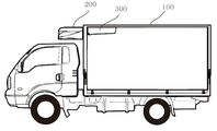
도 1은 본 발명에 따른 냉장/냉동 탑차용 냉각 시스템이 적용될 수 있는 탑차의 형태 및 구조를 도시한 도면,
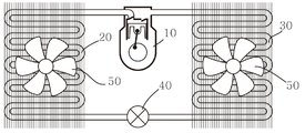
도 2는 냉각 사이클을 이루는 냉각 유닛의 개념도,
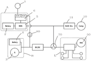
도 3은 본 발명의 바람직한 실시예에 따른 냉장/냉동 탑차용 냉각 시스템의 구성도로서, 대기모드에서의 구성 상태를 도시한 도면,
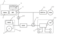
도 4는 본 발명의 바람직한 실시예에 따른 냉장/냉동 탑차용 냉각 시스템의 구성도로서, 주행모드에서의 구성 상태를 도시한 도면,
도 5는 본 발명의 바람직한 실시예에 따른 냉장/냉동 탑차용 냉각 시스템의 구성도로서, 주차모드에서의 구성 상태를 도시한 도면,
도 6은 본 발명의 바람직한 실시예에 따른 냉장/냉동 탑차용 냉각 시스템의 구성도로서, 비상 충전 모드에서의 구성 상태를 도시한 도면이다.1 is a view showing the shape and structure of a tower vehicle to which a cooling system for a refrigerated/frozen tower vehicle according to the present invention can be applied;
2 is a conceptual diagram of a cooling unit forming a cooling cycle,
3 is a block diagram of a cooling system for a refrigeration/freezing tower vehicle according to a preferred embodiment of the present invention, showing a configuration state in a standby mode;
4 is a block diagram of a cooling system for a refrigeration/freezing tower vehicle according to a preferred embodiment of the present invention, showing a configuration state in a driving mode;
5 is a block diagram of a cooling system for a refrigerated/frozen truck according to a preferred embodiment of the present invention, showing a configuration state in a parking mode,
6 is a block diagram of a cooling system for a refrigeration/freezing tower vehicle according to a preferred embodiment of the present invention, and is a view showing a configuration state in an emergency charging mode.
이하, 전술한 본 발명에 따른 냉장/냉동 탑차용 냉각 시스템의 구성을, 본 발명의 바람직한 실시예들이 도시된 첨부 도면을 참조하여 보다 상세히 설명한다.Hereinafter, the configuration of the refrigeration/freezing tower vehicle cooling system according to the present invention will be described in more detail with reference to the accompanying drawings, in which preferred embodiments of the present invention are shown.
또한, 도면에 도시된 구성요소의 크기나 형상 등은 설명의 명료성과 편의상 과장되게 도시될 수 있으며, 본 발명의 구성 및 작용을 고려하여 특별히 정의된 용어들은 사용자, 운용자의 의도 또는 관례에 따라 달라질 수 있고, 이러한 용어들에 대한 정의는 본 명세서 전반에 걸친 내용을 토대로 내려져야 한다.In addition, the size or shape of the components shown in the drawings may be exaggerated for clarity and convenience of description, and terms specifically defined in consideration of the configuration and operation of the present invention may vary depending on the intention or custom of the user or operator And definitions of these terms should be made based on the contents throughout this specification.
도 1은 본 발명에 따른 냉장/냉동 탑차용 냉각 시스템이 적용될 수 있는 냉장/냉동 탑차의 전체 형태 및 구조를 예시한다.1 illustrates the overall shape and structure of a refrigerated/frozen wagon to which a cooling system for a refrigerated/frozen wagon according to the present invention can be applied.
도시된 바와 같이, 냉장/냉동 탑차는 냉각 공간인 격실을 구비한 고(100)를 포함하고, 고(100) 내부 공간에 실내기(300), 고(100) 외측에 실외기(200)를 구비한다.As illustrated, the refrigerated/frozen truck includes a high 100 having a compartment that is a cooling space, an
실외기(200)는 응축기(20) 중심의 장치로서, 확보되는 공간에 따라 기타 부품들이 함께 설치될 수 있고, 실내기(300)는 증발기(30)와 증발기용 블로워 팬(50) 등을 구비하는 장치이다.The
이와 같은 구성에 의해, 외부와 차단된 격실 내에 위치한 실내기(300)의 증발기(30)에서 흡수되는 열기(방출되는 냉기)에 의해 고(100) 내의 온도는 고(100) 외의 온도보다 낮은 온도를 유지할 수 있게 된다.By such a configuration, the temperature in the high 100 by the heat (cold air discharged) absorbed by the
즉, 이러한 냉각 운전은, 압축기, 응축기, 팽창밸브 및 증발기를 거치는 냉매 순환 사이클을 구비한 냉각 유닛의 구동에 의해 이루어지는데, 이를 단순화하여 도식화한 도 2를 통해 냉동 사이클에서 이루어지는 단계별 과정 및 본 발명의 바람직한 실시예에 따라 적용되는 구성을 보다 상세히 설명한다.That is, this cooling operation is performed by driving a cooling unit having a refrigerant circulation cycle through a compressor, a condenser, an expansion valve, and an evaporator. The configuration applied according to the preferred embodiment of the will be described in more detail.
압축기(10)는 흡입-토출 작용을 반복하며 증발기에서 증발한 저온/저압의 기체 냉매를 흡입한 후 압축하여 고온/고압의 냉매 가스로 만들어 응축기로 보내며, 냉각 사이클 전체에서 냉매를 순환시키는 펌프 역할을 한다.The
압축기(10)는 냉각 유닛의 심장과 같은 부품으로서 지속적으로 냉매를 순환시키기 위해 상당한 동력을 필요로 하는데, 기존 탑차용 냉각 유닛의 압축기는 엔진에 동축 연결되어 작동하는 동축 압축기이거나, 전동 모터에 의해 구동되도록 구성되는 경우에도 대체로 속도 고정형의 일반 모터를 사용하여 왔으나, 본 발명의 바람직한 실시예에 따라 본 발명에 적용되는 압축기는 충전 용량이 우수한 리튬 계열 배터리로 이루어진, 엔진 발전기로부터 전력을 공급받아 충전되는 차량용 배터리와는 별도의 냉각용 배터리를 전원으로 하는 속도 가변형 압축기를 적용함으로써, 고(100) 내의 냉각 상황에 따라 RPM을 가변적으로 제어하는 등 효율적인 전력 관리를 할 수 있도록 구성되는 것이 바람직하다.The
또한, 본 발명의 압축기(10)를 구동하는 전동 모터는 브러시리스 직류 모터(Brushless DC Motor, BLDC Motor)인 것이 바람직한데, 기존의 모터가 회전하는 코일에서 발생한 전류를 흘려주기 위해 회전하는 코일에 계속 접촉을 반복해야 하는 브러시가 필수적으로 구비되어야 하는 반면, 브러시리스 직류 모터는 홀센서에 의해 직접 접촉해야하는 브러시를 제외한 구조이기 때문에, 브러시의 접촉 마찰에 의한 에너지 손실이 적어 효율이 높고, 소음이나 미세먼지 발생도 감소되는 전동 모터이다. 따라서, 전력 효율을 극대하해야 하는 본 발명에 적합하다.In addition, the electric motor for driving the
한편, 압축기(10)는 계속적으로 냉매를 순환시키며 저온 저압의 기체 상태의 냉매를 고온, 고압으로 압축하는 기계적 과정을 수행하는 곳이므로, 냉동 사이클의 부조화 등으로 인해 냉매가 액 상태로 유입 시 급격한 압력 변화 등으로 인한 고장이나 수명 저하가 일어날 수 있으니 유의하여야 한다.On the other hand, since the
응축기(20)는 열이 방출되는 곳으로, 압축기에서 토출된 고온/고압의 기체 상태의 냉매를 상온하의 공기에 접촉시켜 열을 제거함(열을 방출함)으로써 냉매를 응축하며 액화시키는 장치이며, 수랭식과 공랭식이 있으나, 도면에서는 열교환 핀과 팬(50)에 의한 공냉식을 예시하고 있다.The
본 발명의 바람직한 실시예에 따라, 종래에 흔히 쓰이는 핀 튜브 방식보다는, 공기와의 접촉 면적을 극대화할 수 있는 브레이징 방식의 플레이트 핀 형태의 열교환기를 적용하는 것도 바람직하다.According to a preferred embodiment of the present invention, it is also preferable to apply a heat exchanger in the form of a plate fin of a brazing method capable of maximizing a contact area with air, rather than a fin tube method commonly used in the related art.
과도한 열이 장시간 발생 될 경우 냉각 능력이 떨어지고, 기계적 손상이 발생할 수 있기 때문에, 팬(50)이나 방열 핀과 같은 효율적인 열교환 수단을 구비하는 것이 바람직하며, 팬(50) 구동 모터 역시 전술한 압축기(10)에서와 마찬가지로 냉각 상태에 따라 즉각적으로 미세하게 전력 소모량을 조절할 수 있도록, 속도 가변형 BLDC 모터로서 적용하는 것이 바람직하다.When excessive heat is generated for a long time, it is preferable to provide an efficient heat exchange means, such as a
팽창밸브(40)는 응축기(20)에서 넘어온 저온/고압의 액 냉매를 증발기에서 증발하기 쉽도록 교축하여 저온/저압 상태로 팽창시켜 주는 장치이며, 통상 기계식으로 작동하는 팽창밸브가 사용되나, 본 발명의 바람직한 실시예에 따라 전원으로 가동되고 정밀 제어가 가능한 전자식 팽창밸브가 사용되는 것도 바람직하다.The
증발기(30)는 팽창밸브(40)에서 넘어온 저온/저압의 액 냉매가 저온/저압의 기체 냉매로 변화하면서 피 냉각 대상(즉, 고 내의 공기)으로부터 열을 흡수하여 증발함으로써 냉동 목적을 직접 달성하는 장치이다. 증발기(30) 역시 원활한 열교환을 위해 열교환 핀이나 팬(50)과 같은 열교환 수단을 구비하는 것이 바람직한데, 증발기(30)의 열교환용 팬(50)은 블로워라고도 부르며, 전력 소모량을 조절하여 효율적으로 전력 관리되도록 연속 제어 가능하게 구성되는 것이 바람직하다.The
이하, 본 발명의 바람직한 실시예에 따른 냉장/냉동 탑차용 냉각 시스템의 전체 구성을 도 3을 참조하여 설명한다.Hereinafter, an entire configuration of a cooling system for a refrigeration/freezing tower vehicle according to a preferred embodiment of the present invention will be described with reference to FIG. 3.
도 3에 도시된 바와 같이, 본 발명은 압축기(10) 및 기타 전력 부하에 전력을 공급하기 위한 전원으로서 적어도 4종류 이상의 전력 공급원을 포함한다.As shown in FIG. 3, the present invention includes at least four types of power sources as power sources for supplying power to the
즉, 본 발명에 따른 냉각 시스템은 외부전원(1), 냉각용 배터리(2), 발전기(3) 및 차량용 배터리(4)의 전원을 포함하는데, 차량의 운행 중 냉각 유닛에서 가장 중요한 전력 부하인 압축기(10)를 구동시키기 위한 전원으로서, 리튬 계열 배터리로 이루어지는 냉각용 배터리(2)를 구비한다.That is, the cooling system according to the present invention includes an external power source (1), a cooling battery (2), a generator (3) and a power source for the vehicle battery (4), which is the most important power load in the cooling unit during operation of the vehicle. As a power source for driving the
상기 냉각용 배터리(2)는 후술할 대기모드에서 220V 교류 전원 등의 외부전원(1)으로부터 전력을 공급받아 전력을 충전하고, 다음 대기모드 이전까지 냉각 유닛 중 특히 압축기(10)의 중요 전원으로서 사용된다.The cooling
냉각용 배터리(2)와 외부전원(1)을 그룹화하여 본 발명에서 냉각용 전원(A)이라고 명명한다.The cooling
한편, 냉각 유닛의 압축기(10) 구동 전력 부하를 제외한 나머지 전력 부하에 전력을 공급하고, 그 밖의 차량 운행에 필요한 일상적인 전력을 공급하기 위한 전원으로서는 차량용 엔진에 직결된 발전기(3) 및 상기 발전기로부터 발생한 전력을 충전하는 차량용 배터리(4)를 구비한다.On the other hand, as a power source for supplying power to the remaining power loads excluding the driving power load of the
차량용 배터리(4)는 차량에 필수적으로 장착된 통상적인 배터리를 의미하며, 보통의 승용차의 경우 12V, 대형 화물차의 경우 24V 배터리가 장착되어 있는 것이 일반적이다.The
냉각 유닛의 전력 부하들 중에서도, 압축기(10) 구동을 제외한 나머지 부하들에는 큰 전력이 소요되지 않기 때문에, 본 발명의 특징적 구성에 따라 차량 엔진이 작동 상태여서 발전기(3) 및 차량용 배터리(4)를 통한 전력 공급이 원활한 경우에는 압축기(10)를 제외한 냉각 유닛의 기타 전력 부하에도 발전기(3) 또는 차량용 배터리(4)의 전력을 공급하도록 구성되는데, 냉각 유닛의 전력 부하들 중 압축기(10)용 전력 부하를 제외한 나머지 전력 부하들을 본 발명에서는 저전력 냉각 부하(L)라고 명명하며, 통상의 차량에 일반적으로 구비된 발전기(3)와 차량용 배터리(4)를 그룹화하여 차량용 전원(B)이라고 명명한다.Among the power loads of the cooling unit, since a large amount of power is not required to loads other than driving the
저전력 냉각 부하(L)에는 응축기(20)와 증발기(30)용 팬(50) 구동용 모터, 전자 팽창 밸브(40), 각종 센서 등이 포함될 수 있다.The low power cooling load L may include a motor for driving the
냉각용 배터리(2)는 효율적으로 관리되어야 하기 때문에, 배터리의 성능이나 수명을 시스템적으로 관리할 수 있는 배터리 매니지먼트 시스템을 구현한 BMS 제어회로(5)가 연결될 수 있고, 여기에 더하여 외부전원(1)이나 기타 전원으로부터 냉각용 배터리(2)로 전력 공급 시 교류를 직류로 전환하여주거나, 직류 전압을 전환하여 주기 위한 교류/직류 컨버터 및/또는 직류/직류 컨버터를 포함하는 충전회로(6)를 더욱 구비할 수 있다.Since the cooling
압축기(10)에는, 전술한 바와 같이 압축기(10)를 구동시키는 속도 가변형 BLDC 모터를 미세 제어할 수 있도록 BLDC 모터 드라이버(11)가 연결되는 것이 바람직하다.As described above, it is preferable that the
한편, 압축기(10)는 높은 동력을 필요로 하기 때문에, 가급적 높은 전압에서 작동하는 모터에 의해 작동되는 것이 바람직하나, 차량에 적용되는 전력 부품의 경우, 고 전압의 부품을 적용하는 것에는 안전상의 우려 때문에 많은 제약이 따른다.On the other hand, since the
따라서, 본 발명에는 별도의 전기 안전 허가 등이 불필요한 범위에서 48V의 구동 전압을 가지는 BLDC 모터를 적용할 수 있는데, 이때에는 상기 압축기(10)에 대해 거의 전용 전원으로 사용되는 냉각용 배터리(2) 역시 전력 공급 과정에서 별도의 전압 전환 등이 불필요하도록 동등한 정도의 48V의 출력 전압을 가지는 것을 적용하는 것이 바람직하다.Therefore, in the present invention, a BLDC motor having a driving voltage of 48V can be applied in a range in which a separate electric safety permit is unnecessary, and in this case, a cooling
한편, 본 발명의 특징적인 구성의 하나로서, 본 발명은 저전력 냉각 부하(L)에, 냉각용 전원(A)과 차량용 전원(B)과의 연결을 선택적으로 전환할 수 있는 전환 스위치(70)를 더욱 포함한다. 이는 저전력 냉각 부하(L)가 전력을 냉각용 전원(A) 또는 차량용 전원(B) 두 그룹 중 하나로부터 선택적으로 공급받을 수 있다는 것을 의미하는 것으로서, 후술할 냉각 시스템의 다양한 운전 모드에서는 상기 전환 스위치(70)가 중요한 역할을 한다. On the other hand, as one of the characteristic configuration of the present invention, the present invention is a low-power cooling load (L), a switching switch (70) that can selectively switch the connection between the cooling power supply (A) and the vehicle power supply (B) It further includes. This means that the low-power cooling load L can receive power selectively from one of two groups: a power supply for cooling (A) or a power supply for vehicles (B). In various driving modes of the cooling system to be described later, the switching switch (70) plays an important role.
여기에 더하여, 차량용 전원(B)과, 냉각용 배터리(2)에 연결된 충전회로(6)의 사이에는 이들간의 전기적 연결을 끊거나 이을 수 있는 온/오프 스위치(80)가 더욱 구비되는데, 해당 구성의 기능에 대해서는 뒤에 보다 상세히 설명한다.In addition to this, an on/off
이하에서는, 차량 운행 상황에 따라 변경되는 본 발명의 바람직한 실시예에 따른 냉장/냉동 탑차용 냉각 시스템의 모드 운전 방식을 도 3 내지 도 6을 참조하여 순차적으로 설명한다.Hereinafter, a mode driving method of a refrigeration/freezing tower vehicle cooling system according to a preferred embodiment of the present invention, which is changed according to a vehicle operation situation, will be sequentially described with reference to FIGS. 3 to 6.
먼저, 도 3은 외부전원(1)이 탑차에 연결된 상태인 대기모드의 구성 상태를 도시한다.First, FIG. 3 shows a configuration state of the standby mode in which the
도시된 바와 같이, 안정적으로 전력 수급이 가능한 외부전원(1)이 연결된 상태이기 때문에, 대기모드에서 냉각 유닛의 운전이 필요한 경우에는, 상기 외부전원(1)으로부터의 전력이 압축기(10) 및 저전력 냉각 부하(L) 전체를 구동하도록 전환 스위치(70)가 연결된 상태임을 확인할 수 있다.As shown, since the
이와 동시에, 외부전원(1)으로부터 전력을 공급받아 냉각용 배터리(2)의 충전이 함께 수행되는데, 충전회로(6)는 교류/직류 컨버터를 포함함으로써, 예를 들어 국내 소비 전력으로 공급되는 일반 전압인 220V의 교류 전류를 48V 전압의 직류 전류로 전환하여 냉각용 배터리(2)에 공급한다.At the same time, the electric power is supplied from the
도 4는 시동이 걸려 엔진이 작동하고 있는 상태인 주행모드에서의 구성 상태를 도시한다.4 shows a configuration state in the driving mode in which the engine is operating because the engine is started.
도시된 바와 같이, 주행모드에서는 엔진으로부터 발생한 동력이 발전기(3)를 가동하여 원활하게 전력을 공급할 수 있는 상태이기 때문에, 해당 전력을 충전할 수 있는 차량용 배터리(4)와 함께 저전력 냉각 부하(L) 및 실내등, 헤드라이트 등 기타 전력 부하에도 전력을 공급할 수 있도록 구성된다.As illustrated, in the driving mode, since the power generated from the engine is in a state capable of smoothly supplying power by operating the
이에 따라, 저전력 냉각 부하(L)에 차량용 전원(B)이 전원을 공급할 수 있도록 전환 스위치(70)가 연결된 상태임을 확인할 수 있다.Accordingly, it can be confirmed that the switching
한편, 예를 들어 차량용 전원(B)으로부터 공급되는 전력의 전압이 12V이고, 저전력 냉각 부하(B)의 구동 전압이 24V인 경우에는, 도시된 바와 같이 전류를 승압하여 공급하기 위한 직류/직류 컨버터가 개재되는 것이 바람직하다.On the other hand, for example, when the voltage of the power supplied from the vehicle power supply B is 12V and the driving voltage of the low-power cooling load B is 24V, a DC/DC converter for boosting and supplying current as shown It is preferred that is interposed.
주목할 점은, 도 3에서와 마찬가지로 차량용 전원(B)과, 냉각용 배터리(2)를 연결하는 온/오프 스위치(80)는 계속 단락된 상태를 유지하고 있다는 것인데, 이는, 엔진의 동력을 직접 압축기(10)의 동력으로 사용하는 경우는 물론, 엔진으로부터 직접적으로 발생한 전력을 전동 압축기의 전원으로 쓰는 경우에도, 압축기의 구동에 따라 많은 양의 전력을 발전기(3) 등으로부터 가져다 쓴다면, 이를 작동시키기 위한 엔진의 효율이 저하될 수밖에 없고, 이는 차량 운행 상의 에너지 효율의 저하를 가져올 뿐만 아니라, 또한 엔진 효율의 저하는 역으로 냉각 성능의 항상성을 저해하는 문제를 일으킬 수도 있기 때문에, 가급적 압축기(10) 구동을 위한 전력 라인과 차량용 전원(B)을 전기적으로 분리하기 위함이다. It should be noted that, as in FIG. 3, the on/off
즉, 본 발명은 엔진 및 엔진 직결 전력원으로부터의 동력원이 냉각 유닛의 압축기로 직접 전달되는 것을 차단함으로써, 엔진 출력저하나 냉각 성능의 저하를 방지하는 원천적인 해법을 제공한다.That is, the present invention provides an original solution to prevent engine power loss or deterioration of cooling performance by blocking direct transmission of power from the engine and the engine direct power source to the compressor of the cooling unit.
도 5는 엔진은 정지되어 있으나, 냉장/냉동 탑차 내의 물류를 하차하는 등의 목적으로 주차나 정차하고 있는 상태인 주차 모드에서의 구성 상태를 도시한다.Fig. 5 shows a configuration state in a parking mode in which the engine is stationary, but is parked or stopped for the purpose of unloading logistics in a refrigerated/frozen truck.
이때에는, 엔진이 정지되어 있기 때문에 발전기(3)로부터의 전력 발생은 0이며, 차량용 배터리(4)의 경우 냉각 유닛 이외의 전력 부하를 감당하기에도 버거운 상태가 될 수 있다.At this time, since the engine is stopped, the power generation from the
따라서, 주차모드에서는, 냉각 유닛은 계속 가동하되 차량용 배터리(4)에 무리를 주지 않기 위해서 냉각용 배터리(2)가 냉각 유닛의 전력 부하 전체를 가동하도록 구성된다.Therefore, in the parking mode, the cooling unit is continuously operated but the cooling
이때, 저전력 냉각 부하(L)의 전력 부하들은 대체로 24V 이하의 저전압 전력부하들이기 때문에, 이들과의 연결 경로에는 전압을 강하하는 직류/직류 컨버터가 개재되는 것이 바람직하다(미도시).At this time, since the power loads of the low-power cooling load L are generally low-voltage power loads of 24 V or less, it is preferable that a DC/DC converter that drops the voltage is interposed in the connection path with them (not shown).
이와 같은 주차모드의 상황은 통상 수 분에서 수십 분의 짧은 시간 동안 발생하기 때문에, 이후에 물류 하차를 완료한 탑차는 다시 냉각용 배터리로서는 최소한의 전력 소모를 위해 압축기(10)만을 가동하는 주행모드나, 안정적인 전력 수급 환경에서 충전이 가능한 대기모드로 돌아가게 된다. Since such a parking mode situation usually occurs for a short time of several minutes to several tens of minutes, the top vehicle that has completed the logistics disembarking afterwards again runs only the
이와 같은 모드 변환에 의한 전력 관리에도 불구하고, 십 수시간 이상의 차량 운행이 계속됨으로써 냉각용 배터리(2)의 충전량이 압축기(10)를 구동하기 어려운 상태까지 떨어지는 경우가 발생할 수도 있다.In spite of the power management by the mode conversion, the vehicle may continue to operate for several tens of hours or more, so that the charging amount of the cooling
도 6은 이러한 비상 상황인 비상 충전 모드에서의 시스템 구성을 나타낸 도면이다.6 is a view showing a system configuration in an emergency charging mode, which is an emergency situation.
도시된 바와 같이, 냉각용 전원(A)은 여전히 압축기(10)를 구동하여야 하는 상황이기 때문에, 전압이나 전류량으로부터 측정된 냉각용 배터리(2)의 잔량이 설정값 이하로 떨어지는 경우에는 차량용 전원(B)의 전력이 냉각용 배터리(2)로 공급될 수 있도록 온/오프 스위치(80)가 임시로 연결된다. 통상의 발전기(3)나 차량용 배터리(4)의 전압은 12V~13V이거나 24V를 넘지 못하기 때문에, 충전회로(6)에서는 이들로부터 인가된 직류 전류를 냉각용 배터리(2)의 전압인 48V로 승압하여 냉각용 배터리(2)에 공급한다.As shown in the figure, since the cooling power supply A is still in a situation where the
이와 동시에, 상기 냉각용 배터리(2)에 걸리는 전력 부하를 최소화하기 위하여, 전환 스위치(70) 역시 저전력 냉각 부하(L)와 냉각용 전원(A)의 연결을 해제하도록 하는 것이 바람직하다.At the same time, in order to minimize the power load applied to the cooling
이상에서 본 발명에 따른 실시예들이 설명되었으나, 이는 예시적인 것에 불과하며, 당해 분야에서 통상적 지식을 가진 자라면 이로부터 다양한 변형 및 균등한 범위의 실시예가 가능하다는 점을 이해할 것이다. 따라서, 본 발명의 진정한 기술적 보호 범위는 다음의 특허청구범위에 의해서 정해져야 할 것이다.Although the embodiments according to the present invention have been described above, they are merely exemplary, and those skilled in the art will understand that various modifications and equivalent ranges of the embodiments are possible therefrom. Therefore, the true technical protection scope of the present invention should be defined by the following claims.
1: 외부전원
2: 냉각용 배터리
3: 발전기
4: 차량용 배터리
5: BMS 제어회로
6: 충전회로
10: 압축기
11: BLDC 모터 드라이버
20: 응축기
30: 증발기
40: 팽창밸브
50: 팬
70: 전환 스위치
80: 온/오프 스위치
100: 고
200: 실외기
300: 실내기1: External power
2: Cooling battery
3: generator
4: Vehicle battery
5: BMS control circuit
6: Charging circuit
10: compressor
11: BLDC motor driver
20: condenser
30: evaporator
40: expansion valve
50: Fan
70: changeover switch
80: on/off switch
100: high
200: outdoor unit
300: indoor unit
Claims (7)
차량용 엔진, 상기 차량용 엔진으로부터 발생된 동력을 전기 에너지로 변환하는 발전기, 상기 발전기로부터의 전기 에너지를 저장하기 위한 차량용 배터리, 상기 차량용 배터리에 비해 상대적으로 고전압으로 작동되며, 상기 냉장/냉동 탑차와는 별도의 외부 전원으로부터 공급된 전기 에너지를 저장하기 위한 냉각용 배터리 및, 직류 모터가 구비된 전동 압축기, 응축기, 팽창밸브 및 증발기를 포함하여 냉각 사이클을 이루는 적어도 하나의 냉각 유닛을 포함하여 구성되며,
통상적인 상황에서는 상기 발전기의 전력이 상기 전동 압축기에 인가되지 않도록 전기적으로 차단됨과 동시에,
상기 차량용 엔진이 작동하여 상기 발전기로부터 전력이 발생되는 주행 모드에서는, 상기 냉각용 배터리 전원은 상기 전동 압축기 구동 전원으로만 사용되며,
상기 차량용 엔진은 작동하지 않으나 상기 외부전원에는 연결되지 않은 주차 모드에서는, 상기 냉각용 배터리 전원은 상기 전동 압축기를 포함한 상기 냉각 유닛 전력 부하 전체의 구동 전원으로 사용되며,
상기 외부전원이 연결된 대기모드에서는 상기 외부전원이 상기 냉각 유닛의 전력 부하 전체의 구동 전원으로 사용됨과 동시에 상기 냉각용 배터리에 충전 전력을 제공하는 것을 특징으로 하는, 냉장/냉동 탑차용 냉각 시스템.
In the high-content cooling system of a refrigeration / refrigeration tower vehicle comprising a compressor, a condenser, an expansion valve, an evaporator,
A vehicle engine, a generator that converts power generated from the vehicle engine into electrical energy, a vehicle battery for storing electric energy from the generator, and is operated at a relatively high voltage compared to the vehicle battery, and is different from the refrigerated/frozen tower vehicle. It comprises a cooling battery for storing electric energy supplied from a separate external power source, and at least one cooling unit that forms a cooling cycle, including an electric compressor equipped with a DC motor, a condenser, an expansion valve, and an evaporator,
Under normal circumstances, the electric power of the generator is electrically cut off so as not to be applied to the electric compressor, and at the same time,
In the driving mode in which the vehicle engine is operated to generate power from the generator, the battery power for cooling is used only as the driving power for the electric compressor,
In the parking mode, in which the vehicle engine does not operate but is not connected to the external power, the battery power for cooling is used as driving power for the entire power load of the cooling unit including the electric compressor,
In the standby mode in which the external power is connected, the external power is used as a driving power for the entire power load of the cooling unit and provides charging power to the cooling battery, and the cooling system for a refrigeration/freezing tower vehicle.
상기 냉각 유닛에서 상기 전동 압축기의 상기 직류 모터를 제외한 상기 증발기, 상기 응축기, 상기 팽창밸브 운전과 관련된 전기부하인 저전력 냉각 부하에는 i) 상기 발전기 및/또는 상기 차량용 배터리를 전원으로 하는 차량용 전원과, ii) 상기 냉각 배터리 및/또는 상기 외부전원을 전원으로 하는 냉각용 전원의 두 그룹 전원의 전력이 전환 공급되며, 이를 위해 상기 저전력 냉각 부하와 상기 차량용 전원, 상기 저전력 냉각 부하와 상기 냉각용 전원 사이의 연결을 선택적으로 전환하기 위한 전환 스위치를 더욱 포함하여 구성된 것을 특징으로 하는, 냉장/냉동 탑차용 냉각 시스템.
According to claim 1,
In the cooling unit, a low-power cooling load that is an electric load related to the evaporator, the condenser, and the expansion valve except for the DC motor of the electric compressor includes i) a vehicle power source using the generator and/or the vehicle battery as a power source; ii) The power of the two groups of cooling power supplying the cooling battery and/or the external power as a power supply is switched, and for this purpose, between the low power cooling load and the vehicle power supply, the low power cooling load and the cooling power supply It characterized in that it further comprises a switching switch for selectively switching the connection of the refrigeration / refrigeration cooling system for a tower car.
상기 냉각용 배터리는 출력전압이 48V이며, 상기 냉각 유닛의 상기 전동 압축기에 구비된 상기 직류 모터는 구동 전압이 48V인 브러시리스 직류 모터(Brushless DC Motor, BLDC Motor)인 것을 특징으로 하는, 냉장/냉동 탑차용 냉각 시스템.
According to claim 2,
The cooling battery has an output voltage of 48V, and the DC motor provided in the electric compressor of the cooling unit is a brushless DC motor (Brushless DC Motor, BLDC Motor) having a driving voltage of 48V. Cooling system for refrigeration trucks.
상기 냉각용 전원과 상기 전환 스위치의 사이에는 48V의 직류 전압을 낮은 전압으로 변환하는 직류/직류 컨버터가 더욱 포함되는 것을 특징으로 하는, 냉장/냉동 탑차용 냉각 시스템.
According to claim 3,
Between the cooling power supply and the changeover switch, further comprising a DC/DC converter for converting a DC voltage of 48V to a low voltage, the cooling system for a refrigeration/freezing tower car.
상기 외부전원이 연결된 상태에서 상기 외부전원으로부터 전력을 공급받는 상기 냉각용 배터리와 상기 외부전원의 사이에는 교류를 직류로 변환하는 교류/직류 컨버터가 포함된 충전회로가 구비되며,
상기 충전회로는 온/오프 스위치를 경유하여 상기 차량용 전원의 전력이 상기 냉각 배터리에 충전되는 것을 허용하기 위한 직류/직류 컨버터를 더욱 포함하는 것을 특징으로 하는, 냉장/냉동 탑차용 냉각 시스템.
The method according to any one of claims 2 to 4,
A charging circuit including an AC/DC converter that converts AC to DC is provided between the cooling battery receiving power from the external power and the external power while the external power is connected,
The charging circuit further includes a DC/DC converter for allowing electric power of the vehicle power source to be charged to the cooling battery via an on/off switch.
상기 온/오프 스위치는 통상적인 상태에서 전기적 연결을 차단하는 오프 상태이며, 상기 냉각 배터리의 잔량이 설정된 전압 또는 전류량의 이하일 경우에만 자동적으로 온 상태로 전환되도록 구성된 것을 특징으로 하는, 냉장/냉동 탑차용 냉각 시스템.
The method of claim 5,
The on/off switch is an off state that cuts off the electrical connection in a normal state, and is configured to automatically switch to the on state only when the remaining amount of the cooling battery is equal to or less than a set voltage or current amount. Dragon cooling system.
상기 온/오프 스위치가 온 상태로 전환되는 경우, 상기 전환 스위치는 상기 저전력 냉각 부하와 상기 차량용 전원을 연결하는 것을 특징으로 하는, 냉장/냉동 탑차용 냉각 시스템.
The method of claim 6,
When the on/off switch is switched to the on state, the switch is characterized in that for connecting the low-power cooling load and the vehicle power supply, refrigeration / refrigeration cooling system for a top vehicle.
Priority Applications (1)
| Application Number | Priority Date | Filing Date | Title |
|---|---|---|---|
| KR1020180157584A KR102162926B1 (en) | 2018-12-07 | 2018-12-07 | Cooling system for refrigerated vehicle |
Applications Claiming Priority (1)
| Application Number | Priority Date | Filing Date | Title |
|---|---|---|---|
| KR1020180157584A KR102162926B1 (en) | 2018-12-07 | 2018-12-07 | Cooling system for refrigerated vehicle |
Publications (2)
| Publication Number | Publication Date |
|---|---|
| KR20200069964A true KR20200069964A (en) | 2020-06-17 |
| KR102162926B1 KR102162926B1 (en) | 2020-10-07 |
Family
ID=71406077
Family Applications (1)
| Application Number | Title | Priority Date | Filing Date |
|---|---|---|---|
| KR1020180157584A Active KR102162926B1 (en) | 2018-12-07 | 2018-12-07 | Cooling system for refrigerated vehicle |
Country Status (1)
| Country | Link |
|---|---|
| KR (1) | KR102162926B1 (en) |
Cited By (5)
| Publication number | Priority date | Publication date | Assignee | Title |
|---|---|---|---|---|
| KR102182838B1 (en) * | 2020-06-19 | 2020-11-25 | 주식회사 벡스시스템스 | Power supply system of refrigerator for special truck |
| KR20220099178A (en) * | 2021-01-05 | 2022-07-13 | 강상원 | Cooling air supply device for live fish vehicles |
| JP2023097422A (en) * | 2021-12-27 | 2023-07-07 | セメス株式会社 | Transfer device and transfer method |
| EP4331879A1 (en) * | 2022-09-02 | 2024-03-06 | Schmitz Cargobull AG | Road vehicle comprising a transport refrigerating machine |
| WO2025182342A1 (en) * | 2024-02-29 | 2025-09-04 | 三菱重工サーマルシステムズ株式会社 | Voltage conversion device, refrigeration cycle system, and vehicle |
Families Citing this family (2)
| Publication number | Priority date | Publication date | Assignee | Title |
|---|---|---|---|---|
| KR102316363B1 (en) | 2021-06-22 | 2021-10-22 | 주식회사 일진정공 | Electric refrigeration container for electric special vehicle |
| KR102539489B1 (en) | 2022-05-27 | 2023-06-05 | 주식회사 일진정공 | Refrigeration container for electric refrigeratoe truck |
Citations (4)
| Publication number | Priority date | Publication date | Assignee | Title |
|---|---|---|---|---|
| JPH10113332A (en) | 1996-10-14 | 1998-05-06 | Fuji Photo Optical Co Ltd | Treatment tool inserting tube for endoscope |
| KR100841257B1 (en) * | 2008-03-24 | 2008-06-25 | 이형주 | Air conditioner refrigeration unit for refrigeration tower |
| JP2014009586A (en) | 2013-01-10 | 2014-01-20 | Hauzesanei Co Ltd | Coping lower part ventilation structure |
| KR20150029883A (en) * | 2013-09-11 | 2015-03-19 | (주)레코디아 | Hybrid Electric Type Apparatus for Cycling Refrigerants Employed in Truck or Van by Using Power Supply of a Solar Cell Array and Power Supply of a generator |
-
2018
- 2018-12-07 KR KR1020180157584A patent/KR102162926B1/en active Active
Patent Citations (4)
| Publication number | Priority date | Publication date | Assignee | Title |
|---|---|---|---|---|
| JPH10113332A (en) | 1996-10-14 | 1998-05-06 | Fuji Photo Optical Co Ltd | Treatment tool inserting tube for endoscope |
| KR100841257B1 (en) * | 2008-03-24 | 2008-06-25 | 이형주 | Air conditioner refrigeration unit for refrigeration tower |
| JP2014009586A (en) | 2013-01-10 | 2014-01-20 | Hauzesanei Co Ltd | Coping lower part ventilation structure |
| KR20150029883A (en) * | 2013-09-11 | 2015-03-19 | (주)레코디아 | Hybrid Electric Type Apparatus for Cycling Refrigerants Employed in Truck or Van by Using Power Supply of a Solar Cell Array and Power Supply of a generator |
Cited By (5)
| Publication number | Priority date | Publication date | Assignee | Title |
|---|---|---|---|---|
| KR102182838B1 (en) * | 2020-06-19 | 2020-11-25 | 주식회사 벡스시스템스 | Power supply system of refrigerator for special truck |
| KR20220099178A (en) * | 2021-01-05 | 2022-07-13 | 강상원 | Cooling air supply device for live fish vehicles |
| JP2023097422A (en) * | 2021-12-27 | 2023-07-07 | セメス株式会社 | Transfer device and transfer method |
| EP4331879A1 (en) * | 2022-09-02 | 2024-03-06 | Schmitz Cargobull AG | Road vehicle comprising a transport refrigerating machine |
| WO2025182342A1 (en) * | 2024-02-29 | 2025-09-04 | 三菱重工サーマルシステムズ株式会社 | Voltage conversion device, refrigeration cycle system, and vehicle |
Also Published As
| Publication number | Publication date |
|---|---|
| KR102162926B1 (en) | 2020-10-07 |
Similar Documents
| Publication | Publication Date | Title |
|---|---|---|
| KR102162926B1 (en) | Cooling system for refrigerated vehicle | |
| CN101583833B (en) | Refrigeration device for refrigeration vehicle | |
| EP2844506B1 (en) | Transport refrigeration system having electric fans | |
| US20180222278A1 (en) | Refrigeration device and container refrigeration system | |
| US7043931B2 (en) | Method and apparatus for cooling interior spaces of vehicles | |
| US20190105969A1 (en) | Transport refrigeration unit | |
| US11964536B2 (en) | Vehicular heat exchange system and motor unit used in same | |
| EP3481665A1 (en) | High voltage system for a transport refrigeration unit | |
| EP2668051B1 (en) | Efficient control algorithm for start-stop operation of refrigeration unit powered by an engine | |
| US9211881B2 (en) | Control system for auxiliary power unit of a vehicle | |
| KR102162925B1 (en) | Multiple compressor cooling system for refrigerated vehicle | |
| KR20210027612A (en) | System of refrigeration for electic vehicle using independent power source | |
| JP7311279B2 (en) | transportation refrigeration machinery | |
| CN221819842U (en) | Radiator and engineering vehicle | |
| KR20090083543A (en) | Refrigeration equipment for refrigeration vehicles with a high power generator | |
| KR102085560B1 (en) | Cooling system for refrigerated vehicle | |
| CN216101432U (en) | Automobile air conditioner control system | |
| JP7208066B2 (en) | transportation refrigeration machinery | |
| CN103522964B (en) | Automobile auxiliary refrigeration device, automobile refrigeration system and automobile | |
| JP2004225991A (en) | On-vehicle refrigeration unit | |
| JP2020108267A (en) | Power supply system, transportation refrigerator, and vehicle | |
| JP2015033205A (en) | Vehicular temperature controlling device | |
| CN115610177B (en) | Automobile air conditioning control system | |
| JP2013113548A (en) | Cooling storage device for vehicle | |
| JP3219210U (en) | Refrigeration system for shipping refrigeration containers |
Legal Events
| Date | Code | Title | Description |
|---|---|---|---|
| PA0109 | Patent application |
Patent event code: PA01091R01D Comment text: Patent Application Patent event date: 20181207 |
|
| PA0201 | Request for examination | ||
| PE0902 | Notice of grounds for rejection |
Comment text: Notification of reason for refusal Patent event date: 20200310 Patent event code: PE09021S01D |
|
| PG1501 | Laying open of application | ||
| E701 | Decision to grant or registration of patent right | ||
| PE0701 | Decision of registration |
Patent event code: PE07011S01D Comment text: Decision to Grant Registration Patent event date: 20200917 |
|
| GRNT | Written decision to grant | ||
| PR0701 | Registration of establishment |
Comment text: Registration of Establishment Patent event date: 20200928 Patent event code: PR07011E01D |
|
| PR1002 | Payment of registration fee |
Payment date: 20200928 End annual number: 3 Start annual number: 1 |
|
| PG1601 | Publication of registration | ||
| PR1001 | Payment of annual fee |
Payment date: 20240617 Start annual number: 5 End annual number: 5 |