KR20200066200A - Rotation mechanism of industrial machinery, speed reducer, industrial machine and drive device - Google Patents
Rotation mechanism of industrial machinery, speed reducer, industrial machine and drive device Download PDFInfo
- Publication number
- KR20200066200A KR20200066200A KR1020190154024A KR20190154024A KR20200066200A KR 20200066200 A KR20200066200 A KR 20200066200A KR 1020190154024 A KR1020190154024 A KR 1020190154024A KR 20190154024 A KR20190154024 A KR 20190154024A KR 20200066200 A KR20200066200 A KR 20200066200A
- Authority
- KR
- South Korea
- Prior art keywords
- gear
- industrial machine
- reduction
- input
- unit
- Prior art date
Links
Images


Classifications
-
- F—MECHANICAL ENGINEERING; LIGHTING; HEATING; WEAPONS; BLASTING
- F16—ENGINEERING ELEMENTS AND UNITS; GENERAL MEASURES FOR PRODUCING AND MAINTAINING EFFECTIVE FUNCTIONING OF MACHINES OR INSTALLATIONS; THERMAL INSULATION IN GENERAL
- F16H—GEARING
- F16H57/00—General details of gearing
- F16H57/02—Gearboxes; Mounting gearing therein
- F16H57/029—Gearboxes; Mounting gearing therein characterised by means for sealing the gearboxes, e.g. to improve airtightness
-
- F—MECHANICAL ENGINEERING; LIGHTING; HEATING; WEAPONS; BLASTING
- F16—ENGINEERING ELEMENTS AND UNITS; GENERAL MEASURES FOR PRODUCING AND MAINTAINING EFFECTIVE FUNCTIONING OF MACHINES OR INSTALLATIONS; THERMAL INSULATION IN GENERAL
- F16H—GEARING
- F16H1/00—Toothed gearings for conveying rotary motion
- F16H1/28—Toothed gearings for conveying rotary motion with gears having orbital motion
- F16H1/32—Toothed gearings for conveying rotary motion with gears having orbital motion in which the central axis of the gearing lies inside the periphery of an orbital gear
-
- B—PERFORMING OPERATIONS; TRANSPORTING
- B25—HAND TOOLS; PORTABLE POWER-DRIVEN TOOLS; MANIPULATORS
- B25J—MANIPULATORS; CHAMBERS PROVIDED WITH MANIPULATION DEVICES
- B25J9/00—Programme-controlled manipulators
- B25J9/10—Programme-controlled manipulators characterised by positioning means for manipulator elements
- B25J9/102—Gears specially adapted therefor, e.g. reduction gears
-
- F—MECHANICAL ENGINEERING; LIGHTING; HEATING; WEAPONS; BLASTING
- F16—ENGINEERING ELEMENTS AND UNITS; GENERAL MEASURES FOR PRODUCING AND MAINTAINING EFFECTIVE FUNCTIONING OF MACHINES OR INSTALLATIONS; THERMAL INSULATION IN GENERAL
- F16H—GEARING
- F16H57/00—General details of gearing
- F16H57/02—Gearboxes; Mounting gearing therein
- F16H2057/02039—Gearboxes for particular applications
- F16H2057/02069—Gearboxes for particular applications for industrial applications
- F16H2057/02073—Reduction gearboxes for industry
Landscapes
- Engineering & Computer Science (AREA)
- General Engineering & Computer Science (AREA)
- Mechanical Engineering (AREA)
- Robotics (AREA)
- Retarders (AREA)
- General Details Of Gearings (AREA)
- Gear Transmission (AREA)
Abstract
Description
본 발명은, 산업 기계의 회전 기구, 감속기, 산업 기계 및 구동 장치에 관한 것이다.The present invention relates to a rotating mechanism, a reducer, an industrial machine, and a driving device for an industrial machine.
예를 들어 일본 특허 제5356462호 공보에 개시되어 있는 바와 같이, 산업 기계의 회전 기구에 감속기가 사용되고 있다. 일본 특허 제5356462호 공보에 개시된 감속기는, 복수의 입력 기어와 맞물리는 원통 형상 기어와, 원통 형상 기어에 맞물리는 아이들 기어를 갖고 있다. 모터로부터 아이들 기어에 입력된 회전이, 원통형 기어를 통해 복수의 입력 기어에 전달된다. 감속기는, 모터로부터 입력된 회전을 감속하여, 케이스와 캐리어의 상대 회전으로서 출력한다. 일본 특허 제5356462호 공보에서는, 케이스가 산업용 로봇의 제1 부재와 고정되고, 캐리어는 산업용 로봇의 제2 부재와 고정되어 있다.For example, as disclosed in Japanese Patent No. 5,646,646, a reducer is used in a rotating mechanism of an industrial machine. The reducer disclosed in Japanese Patent Publication No. 5,646,2 has a cylindrical gear engaged with a plurality of input gears, and an idle gear engaged with the cylindrical gear. The rotation input from the motor to the idle gear is transmitted to a plurality of input gears through a cylindrical gear. The reducer decelerates the rotation input from the motor and outputs it as a relative rotation between the case and the carrier. In Japanese Patent Publication No. 5,646,2, the case is fixed with the first member of the industrial robot, and the carrier is fixed with the second member of the industrial robot.
그런데, 일본 특허 제5356462호 공보에 개시된 구조에서는, 산업용 로봇의 제2 부재는, 원통 형상 기어 및 아이들 기어와, 캐리어의 동일한 측에 배치되어 있다. 이 때문에, 캐리어의 제2 부재의 측에 있어서, 캐리어의 원주 방향을 따른 일부와 대면하는 영역에 아이들 기어 및 모터가 배치되게 된다.By the way, in the structure disclosed in Japanese Patent No. 5,646,2, the second member of the industrial robot is disposed on the same side of the cylindrical gear and the idle gear and the carrier. For this reason, the idle gear and the motor are arranged on the side of the second member of the carrier in a region facing a part along the circumferential direction of the carrier.
제2 부재는, 통상, 캐리어에 대하여 볼트를 사용하여 고정된다. 단, 캐리어의 원주 방향을 따른 일부와 대면하는 영역이 아이들 기어 및 모터에 의해 점유되어 있다. 따라서, 제2 부재를 고정하기 위한 복수의 고정용 볼트의 배치가, 아이들 기어 및 모터에 의해 제약을 받고, 대칭성을 상실하여 불연속으로 된다. 고정용 볼트의 배치가 대칭성을 상실하면, 제2 부재의 동작 시에 감속기에 큰 힘이 가해지는 경우도 있다. 감속에 큰 힘이 가해지면, 감속기로부터 윤활유가 누설되고, 나아가 감속기에 프레팅 등의 손상이 발생할 수 있다.The second member is usually fixed to the carrier using bolts. However, the region facing a part along the circumferential direction of the carrier is occupied by the idle gear and the motor. Therefore, the arrangement of the plurality of fixing bolts for fixing the second member is restricted by the idle gear and the motor, and is lost due to loss of symmetry. When the arrangement of the fixing bolt loses symmetry, a large force may be applied to the reducer during operation of the second member. When a large force is applied to the deceleration, lubricating oil may leak from the decelerator, and further damage such as fretting may occur.
본 발명은, 이상의 점을 고려하여 이루어진 것이고, 감속기를 산업 기계에 고정하기 위한 고정용 볼트의 배치 자유도를 개선하여, 산업 기계에 감속기를 안정되게 고정할 수 있도록 하는 것을 목적으로 한다.This invention is made|formed in view of the above, and it aims at improving the freedom of arrangement|positioning of the fixing bolt for fixing a reduction gear to an industrial machine, and making it possible to stably fix a reduction gear to an industrial machine.
본 발명에 의한 제1 산업 기계의 회전 기구는,The rotating mechanism of the first industrial machine according to the present invention,
산업 기계의 제1 부재와,A first member of an industrial machine,
상기 제1 부재에 고정되는 케이스와,A case fixed to the first member,
상기 케이스에 보유 지지되어 회전 입력을 감속하여 출력부로부터 출력하는 감속부와,A reduction unit which is held in the case to decelerate the rotational input and output it from the output unit;
상기 출력부와 고정되는 산업 기계의 제2 부재와,A second member of the industrial machine fixed with the output part,
상기 제1 부재측에 배치되어 상기 감속부에 회전을 입력하는 센터 기어와,A center gear disposed on the first member side to input rotation to the reduction unit;
상기 센터 기어에 맞물림과 함께 구동부의 출력 기어에 맞물려 제1 부재측에 배치된 중간 기어를 구비한다.It is provided with an intermediate gear which is arranged on the first member side in engagement with the output gear of the driving part with the center gear.
본 발명에 의한 제2 산업 기계의 회전 기구는,The rotating mechanism of the second industrial machine according to the present invention,
산업 기계의 제1 부재와,A first member of an industrial machine,
상기 제1 부재에 고정되는 케이스와,A case fixed to the first member,
상기 케이스에 보유 지지되어 입력 기어에 입력되는 회전을 감속하여 출력부로부터 출력하는 감속부와,A reduction unit which is held by the case and decelerates the rotation input to the input gear to output from the output unit;
상기 감속부의 상기 출력부와 고정되는 제2 부재와,A second member fixed to the output unit of the reduction unit,
상기 감속부의 상기 제2 부재측과는 반대측에 배치되어 상기 입력 기어와 맞물리는 센터 기어와,A center gear disposed on a side opposite to the second member side of the reduction unit and engaged with the input gear;
상기 센터 기어와 맞물려, 구동부로부터 회전이 입력되는 중간 기어를 구비한다.The intermediate gear is engaged with the center gear, and rotation is input from the driving unit.
본 발명에 의한 제1 또는 제2 산업 기계의 회전 기구에 있어서, 상기 중간 기어는, 상기 감속부로부터 축 방향으로 시프트하여 배치되어 있어도 된다.In the rotating mechanism of the first or second industrial machine according to the present invention, the intermediate gear may be arranged by shifting in the axial direction from the reduction unit.
본 발명에 의한 제1 또는 제2 산업 기계의 회전 기구에 있어서, 상기 센터 기어는 통 형상의 부재이도록 해도 된다.In the rotating mechanism of the first or second industrial machine according to the present invention, the center gear may be a cylindrical member.
본 발명에 의한 제1 또는 제2 산업 기계의 회전 기구에 있어서, 상기 감속부는, 상기 입력 기어를 포함하는 회전 가능한 축 부재와, 상기 축 부재가 삽입된 관통 구멍을 갖는 보유 지지부와, 상기 관통 구멍을 상기 제2 부재의 측으로부터 막는 캡을 갖게 해도 된다.In the rotating mechanism of the first or second industrial machine according to the present invention, the reduction unit includes a rotatable shaft member including the input gear, a holding portion having a through hole in which the shaft member is inserted, and the through hole You may have a cap which blocks the side member from the side of the second member.
본 발명에 의한 제1 또는 제2 산업 기계의 회전 기구가, 회전 대칭인 위치에 배치되어 상기 제2 부재를 상기 감속부에 고정하는 복수의 볼트를 구비하게 해도 된다.The rotating mechanism of the first or second industrial machine according to the present invention may be provided in a plurality of bolts that are arranged at rotationally symmetrical positions to secure the second member to the reduction unit.
본 발명에 의한 제1 또는 제2 산업 기계의 회전 기구에 있어서, 상기 중간 기어는, 직경 방향에 있어서, 상기 보유 지지부의 외측 에지보다도 내측에 위치하고 있어도 된다.In the rotating mechanism of the first or second industrial machine according to the present invention, the intermediate gear may be located in the radial direction, inside the outer edge of the holding portion.
본 발명에 의한 제1 또는 제2 산업 기계의 회전 기구에 있어서, 상기 중간 기어와 맞물리는 상기 구동부의 상기 출력 기어는, 직경 방향에 있어서, 상기 보유 지지부의 외측 에지보다도 내측에 위치하고 있어도 된다.In the rotating mechanism of the first or second industrial machine according to the present invention, the output gear of the driving part engaged with the intermediate gear may be located inside the outer edge of the holding part in the radial direction.
본 발명에 의한 제1 또는 제2 산업 기계의 회전 기구에 있어서, 상기 제1 부재의 상기 케이스와 고정된 부분은, 축 방향에 있어서, 상기 감속부의 입력 기어보다도 제2 부재측에 위치하고 있어도 된다.In the rotating mechanism of the first or second industrial machine according to the present invention, the case and the fixed portion of the first member may be located on the second member side in the axial direction, rather than the input gear of the reduction unit.
본 발명에 의한 제1 또는 제2 산업 기계의 회전 기구에 있어서, 상기 제1 부재의 상기 케이스와 고정된 부분은, 축 방향에 있어서, 상기 중간 기어보다도 제2 부재측에 위치하고 있어도 된다.In the rotating mechanism of the first or second industrial machine according to the present invention, the case and the fixed portion of the first member may be located on the second member side than the intermediate gear in the axial direction.
본 발명에 의한 산업 기계는, 상술한 본 발명에 의한 제1 및 제2 회전 기구의 어느 것을 구비한다.The industrial machine according to the present invention includes any of the first and second rotating mechanisms according to the present invention described above.
본 발명에 의한 제1 감속기는,The first reducer according to the present invention,
산업 기계의 제1 부재에 고정되는 케이스와,A case fixed to the first member of the industrial machine,
상기 케이스에 보유 지지되어 회전 입력을 감속하여 산업 기계의 제2 부재에 출력하는 감속부와,A reduction unit which is held in the case to decelerate the rotation input and output it to the second member of the industrial machine,
제1 부재측에 배치되어 상기 감속부에 회전을 입력하는 센터 기어와,A center gear disposed on the first member side to input rotation to the reduction unit;
상기 센터 기어에 맞물려 제1 부재측에 배치된 중간 기어를 구비한다.An intermediate gear is disposed on the first member side in engagement with the center gear.
본 발명에 의한 제2 감속기는,The second reducer according to the present invention,
산업 기계의 제1 부재에 고정되는 케이스와,A case fixed to the first member of the industrial machine,
상기 케이스에 보유 지지되어, 입력 기어에 입력되는 회전을 감속하여 산업 기계의 제2 부재에 출력하는 감속부와,A reduction unit which is held in the case and decelerates the rotation input to the input gear and outputs it to the second member of the industrial machine,
상기 감속부의 상기 제2 부재측과는 반대측에 배치되어 상기 입력 기어와 맞물리는 센터 기어와,A center gear disposed on a side opposite to the second member side of the reduction unit and engaged with the input gear;
상기 센터 기어와 맞물려, 구동부로부터 회전이 입력되는 중간 기어를 구비한다.The intermediate gear is engaged with the center gear, and rotation is input from the driving unit.
본 발명에 의한 제3 감속기는,The third reducer according to the present invention,
산업 기계의 제1 부재 및 제2 부재 사이에 배치되어 상기 제1 부재에 고정된 케이스와,A case disposed between the first member and the second member of the industrial machine and fixed to the first member,
상기 케이스에 보유 지지되어, 입력 기어에 입력되는 회전을 감속하여 상기 제2 부재에 출력하는 감속부와,A reduction unit which is held in the case and decelerates the rotation input to the input gear and outputs it to the second member;
상기 감속부와 상기 제1 부재 사이에 배치되어, 상기 입력 기어와 맞물리는 센터 기어와,A center gear disposed between the reduction unit and the first member and engaged with the input gear;
상기 감속부와 상기 제1 부재 사이에 배치되어, 상기 센터 기어와 맞물리는 중간 기어를 구비한다.It is disposed between the reduction unit and the first member, and has an intermediate gear engaged with the center gear.
본 발명에 의한 구동 장치는,The driving device according to the present invention,
본 발명에 의한 제1 내지 제3 감속기의 어느 것과,Any of the first to third reducers according to the present invention,
상기 감속기에 회전을 입력하는 구동부를 구비한다.It has a driving unit for inputting the rotation to the reducer.
본 발명에 따르면, 감속기를 산업 기계에 고정하기 위한 고정용 볼트의 배치 자유도를 개선하여, 산업 기계에 감속기를 안정되게 고정할 수 있도록 하는 것을 목적으로 한다.According to the present invention, it is an object of the present invention to improve the degree of freedom of arrangement of a fixing bolt for fixing a reducer to an industrial machine, and to stably fix the reducer to an industrial machine.
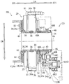
도 1은, 일 실시 형태를 설명하기 위한 도면이며, 산업 기계의 회전 기구를 도시하는 단면도이다.
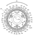
도 2는, 도 1의 산업 기계에 내장된 감속기를 제1 부재측에서 도시하는 평면도이다.
도 3은, 도 1의 산업 기계에 내장된 감속기를 제2 부재측에서 도시하는 평면도이다.
도 4는, 산업 기계의 일례를 나타내는 사시도이다.1 is a view for explaining an embodiment, and is a cross-sectional view showing a rotating mechanism of an industrial machine.
Fig. 2 is a plan view showing a reducer incorporated in the industrial machine of Fig. 1 from the first member side.
3 is a plan view showing a reducer incorporated in the industrial machine of FIG. 1 from the second member side.
4 is a perspective view showing an example of an industrial machine.
이하, 도면을 참조하면서 본 발명의 일 실시 형태에 대하여 설명한다. 도 1 내지 도 3은, 본 실시 형태에 관한 회전 기구(RM) 및 구동 장치(DD)의 일 구체예를 도시하는 단면도 또는 사시도이다. 회전 기구(RM)는, 상세하게는 후술하는 바와 같이, 산업 기계(IM)의 제1 부재(11) 및 제2 부재(12)를 상대 동작, 보다 구체적으로는 상대 회전시키는 기구이다. 회전 기구(RM)는, 제1 부재(11) 및 제2 부재(12)와, 제1 부재(11)에 고정된 케이스(25)와, 제2 부재(12)에 고정된 감속부(30)를 갖고 있다. 또한, 구동 장치(DD)는, 케이스(25) 및 감속부(30)를 포함하는 감속기(20)와, 감속기(20)에 회전을 입력하는 구동부(50)를 갖고 있다.Hereinafter, one embodiment of the present invention will be described with reference to the drawings. 1 to 3 are cross-sectional or perspective views showing one specific example of the rotation mechanism RM and the drive device DD according to the present embodiment. The rotation mechanism RM is a mechanism for relative motion, and more specifically, relative rotation of the
이하에 설명하는 본 실시 형태에 있어서는, 감속기(20)를 산업 기계(IM)에 고정하기 위한 고정용 볼트의 배치 자유도를 개선하기 위한 고안이 이루어져 있다. 이 고안에 의해, 안정되게 고정된 상태에서 감속기(20)를 산업 기계(IM)에 내장할 수 있다.In the present embodiment described below, a design has been made to improve the degree of freedom in the arrangement of the fixing bolts for fixing the
회전 기구(RM)나 구동 장치(DD)가 적용되는 산업 기계(IM)의 일례로서, 도 4에 도시한 바와 같이, 산업용의 로봇(R)을 예시할 수 있다. 보다 구체적으로는, 로봇의 선회동이나 팔 관절 등의 선회부, 각종 공작 기계의 선회부 등에, 회전 기구(RM)나 구동 장치(DD)가 적용될 수 있다.As an example of the industrial machine IM to which the rotation mechanism RM or the driving device DD is applied, as shown in FIG. 4, the industrial robot R can be illustrated. More specifically, a rotating mechanism RM or a driving device DD may be applied to a turning portion of a robot, a turning portion such as an arm joint, or a turning portion of various machine tools.
도 1은, 도 4에 도시된 산업 기계(IM)에 있어서의 감속기(20)의 베이스(RB) 및 선회동(RA)으로의 접속부를 도시하고 있다. 도 1에 도시된 구체예에 있어서, 로봇(R)의 베이스(RB)에 케이스(25)가 고정되어, 로봇(R)의 선회동(RA)에 감속부(30)가 접속되어 있다. 이 예에서는, 로봇(R)의 베이스(RB)가 제1 부재(11)를 구성하고, 선회동(RA)이 제2 부재(12)를 구성하고 있다. 도 1에 도시된 예에서는, 제1 부재(11)는 케이싱으로서 구성되어 있고, 제2 부재(12)는 암재로서 구성되어 있다. 제2 부재(12)와 고정된 감속부(30)는, 입력된 회전을 감속하여 제2 부 재(12)에 출력한다. 따라서, 도시된 예에서는, 베이스(RB)에 대하여 선회동(RA)을 고토크로 회전시키고 또한 당해 선회동(RA)의 회전량이나 회전 위치를 고정밀도로 제어할 수 있다.FIG. 1 shows a connection portion of the
이어서, 감속기(20)에 대하여 설명한다. 도 1에 도시한 바와 같이, 감속기(20)는, 케이스(25)와, 케이스(25)에 보유 지지된 감속부(30)를 갖고 있다. 상술한 바와 같이, 케이스(25)는, 산업 기계(IM)의 제1 부재(11)(도시된 예에 있어서, 베이스(RB))에 고정된다. 감속부(30)는, 구동부(50)가 출력한 회전을 입력하게 된다. 감속부(30)는, 입력된 회전을 감속하여, 출력부(34a)로부터 출력한다. 이때, 출력부(34a)는, 회전 축선(RA)을 중심으로 하여 회전한다. 산업 기계(IM)의 제2 부재(12)(도시된 예에 있어서, 선회동(RA))는, 감속부(30)의 출력부(34a)에 접속하고 있다. 따라서, 감속부(30)는, 입력되는 동력의 회전 속도를 감속하고, 토크가 증대된 동력을 제2 부재(12)에 전달한다. 제2 부재(12)는, 케이스(25)에 고정된 제1 부재(11)에 대하여, 회전 축선(RA)을 중심으로 하여 상대 회전한다.Next, the
이하에 있어서, 회전 축선(RA)과 평행한 방향을 축 방향(DA)으로 하고, 회전 축선(RA)과 직교하는 방향을 직경 방향(DR)으로 하고, 회전 축선(RA)을 중심으로 하는 원주를 따른 방향을 원주 방향(DC)으로 한다. 원주 방향(DC)은, 직경 방향(DR)과 직교한다.In the following, the direction parallel to the rotation axis RA is the axial direction DA, the direction orthogonal to the rotation axis RA is the radial direction DR, and the circumference centered on the rotation axis RA. The direction along is the circumferential direction (DC). The circumferential direction DC is orthogonal to the radial direction DR.
감속부(30)는, 전형적으로는, 유성 기어 감속부 혹은 편심 요동형 감속부로서 구성하는 것이 가능하지만, 감속부(30)의 구체적인 구성은 특별히 한정되지 않는다. 따라서, 유성 기어 감속부 및 편심 요동형 감속부가 조합된 감속 구조에 의해 감속부(30)가 구성되어도 되고, 다른 임의의 방식의 감속 구조에 의해 감속부(30)가 구성되어도 된다.The
도시된 예에 있어서, 감속부(30)는, 편심 요동형의 기구를 갖고 있다. 도시된 감속부(30)는, 구동부(50)로부터의 회전을 전달되는 축 부재(32)와, 축 부재(32)를 회전 가능하게 지지하는 보유 지지부(34)와, 보유 지지부(34)에 요동 회전 가능하게 지지된 요동 기어(36)를 갖고 있다. 축 부재(32)는, 축 방향(DA)과 평행한 축선을 중심으로 하여 회전 가능하게 되어 있다. 축 부재(32)는, 축 방향(DA)에 있어서의 일측(S1)에, 입력 기어(32a)를 갖고 있다. 구동부(50)로부터의 회전은, 이 입력 기어(32a)에 전달된다.In the illustrated example, the
보유 지지부(34)는, 소위 캐리어로서 기능한다. 도시된 예에 있어서, 보유 지지부(34)는, 등간격을 두고 원주 방향(DC)으로 이격한 위치에, 3개의 축 부재(32)를 각각 회전 가능하게 지지하고 있다(도 2 참조). 각 축 부재(32)는, 원기둥 형상의 편심체(도시하지 않음)를 갖고, 소위 크랭크축을 구성하고 있다. 편심체는, 축 부재(32)의 회전 축선으로부터 편심되어 배치되어 있다. 요동 기어(36)는, 편심체를 수용하는 구멍(도시하지 않음)을 갖고 있다.The holding
요동 기어(36)는, 축 부재(32)의 회전 시에 편심체에 의해 구동되어, 보유 지지부(34)에 대하여 편심 요동한다. 바꾸어 말하면, 요동 기어(36)는, 축 부재(32)의 회전 시에 편심체에 의해 구동되어, 회전 축선(RA)을 중심으로 한 원주 궤적을 따라서 병진 운동한다. 요동 기어(36)의 외치는, 케이스(25)의 내주면에 마련된 내치와 맞물린다. 요동 기어(36)의 외치의 잇수와, 케이스(25)의 내치의 잇수가 상이하다. 이 결과, 요동 기어(36)를 지지하는 보유 지지부(34)는, 축 부재(32)에 회전에 따라, 회전 축선(RA)을 중심으로 하여 케이스(25)에 대하여 상대 회전한다. 즉, 도시된 예에 있어서, 캐리어로서 구성된 보유 지지부(34)가, 감속부(30)의 출력부(34a)를 구성하고 있다.The
또한, 각 축 부재(32)에는, 위상을 180° 시프트하여 배치된 2개의 편심체, 바꾸어 말하면 축 부재(32)의 회전 축선으로부터 진역으로 되는 방향으로 편심된 2개의 편심체가 마련되어 있다. 보유 지지부(34)는, 2개의 요동 기어(36)를 보유 지지하고 있다. 2개의 요동 기어(36)는, 위상을 180° 시프트하여 배치되어 있다.In addition, each of the
도시된 예에 있어서, 보유 지지부(34)는, 각 축 부재(32)에 대응하여 각각 마련된 구멍(34b)을 갖고 있다. 도시된 예에 있어서, 보유 지지부(34)에는 각 축 부재(32)에 대응하여 한 쌍의 구멍(34b)이 마련되어 있다. 도 3에 도시한 바와 같이, 축 방향(DA)에 있어서의 타측(S2)의 구멍(34b)에는, 캡(38)이 마련되어 있다. 이 구멍(34b)은, 캡(38)에 의해 축 방향(DA)에 있어서의 타측(S2)으로부터 막아져 있다.In the illustrated example, the holding
또한, 상술한 바와 같이, 도시된 감속부(30)의 구성은 일례에 지나지 않는다. 예를 들어 감속부(30)가, 유성 기어형의 기구를 갖게 해도 된다. 유성 기어형의 감속부(30)는, 구동부(50)로부터의 회전을 전달하는 입력 기어로서의 유성 기어와, 유성 기어를 회전 가능하게 지지한 보유 지지부(캐리어)를 갖는다. 이 예에 있어서, 보유 지지부(캐리어)(34)가 감속부(30)의 출력부를 구성하도록 해도 된다.In addition, as described above, the configuration of the illustrated
도 1에 도시한 바와 같이, 감속부(30)의 출력부(34a)를 이루는 보유 지지부(34)는, 볼트(B2)를 통해, 산업 기계(IM)의 제2 부재(12)에 접속하고 있다. 도시된 예에서는, 제2 부재(12)의 관통 구멍(도시하지 않음)을 관통한 볼트(B2)가, 보유 지지부(34)에 형성된 볼트 구멍(34c)에 맞물림으로써, 감속부(30)와 제2 부 재(12)가 체결된다. 볼트 구멍(34c)에는, 볼트(B2)의 나사와 맞물리는 나사가 형성되어 있다.As shown in FIG. 1, the holding
제2 부재(12)는, 축 방향(DA)에 있어서의 타측(S2)으로부터 보유 지지부(34)와 대면하고 있다. 도 3에 도시된 예에 있어서, 보유 지지부(34)에는, 다수의 볼트 구멍(34c), 보다 구체적으로는 12개의 볼트 구멍(34c)이 마련되어 있다. 특히 도시된 예에 있어서, 보유 지지부(34)에 마련된 볼트 구멍(34c)은, 회전 대칭으로 배치되어 있다. 도시된 예에서는, 원주 방향(DC)에 인접하는 2개의 축 부재(32)(캡(38)) 사이에 복수의 볼트 구멍(34c)(도시된 예에서는 4개의 볼트 구멍(34c))이 원주 방향(DC)으로 등간격을 두고 마련되어 있다. 그리고, 도시된 예에 있어서, 볼트 구멍(34c)의 배치는, 보유 지지부(34)의 축 방향(DA)에 있어서의 타측면 상에, 3회 대칭으로 되어 있다.The
또한, 도 1에 도시한 바와 같이, 감속기(20)는, 감속부(30)의 중앙을 관통하는 통 형상 부재(31)를 더 갖고 있다. 통 형상 부재(31)는, 볼트(B3)를 사용하여 보유 지지부(34)에 고정되어 있다. 통 형상 부재(31)는, 감속부(30)의 보유 지지부(34) 및 감속부(30)에 고정된 제2 부재(12)와 함께, 제1 부재(11)에 대하여 상대 회전한다. 통 형상 부재(31)는, 그 중심 축선이 회전 축선(RA) 상에 위치하도록 하여, 배치되어 있다.In addition, as shown in FIG. 1, the
케이스(25)는, 통 형상으로 형성되어 있다. 케이스(25)는, 적어도 부분적으로 감속부(30)를 수용한다. 도시된 케이스(25)는, 원통 형상의 부재로서 형성되어 있다. 상술한 바와 같이, 케이스(25)의 내주면에는 축 방향(DA)으로 연장되는 내치(도시하지 않음)가 마련되어 있다. 이 내치는, 요동 기어(36)의 외치와 맞물린다. 케이스(25)는, 도시하지 않은 베어링을 통해 감속부(30)의 보유 지지부(34)를 회전 가능하게 보유 지지하고 있다.The
한편, 케이스(25)의 외주면에는, 직경 방향(DR)에 있어서의 외측으로 돌출된 환상의 플랜지(26)가 마련되어 있다. 플랜지(26)에는, 등간격을 두고 원주 방향(DC)에 배치된 다수의 관통 구멍(26a), 도시된 예에서는 16개의 관통 구멍(26a)이, 마련되어 있다. 케이스(25)는, 관통 구멍(26a)을 통과한 볼트(B1)를 사용하여 제1 부재(11)와 고정된다. 보다 구체적으로는, 플랜지(26)의 관통 구멍(26a) 및 제1 부재(11)의 관통 구멍을 통과한 볼트(B1)에 너트가 맞물림으로써, 케이스(25)와 제1 부재(11)가 체결되어 있다. 단, 이 예에 한정되지 않고, 플랜지(26) 및 제1 부재(11)의 한쪽에 형성된 관통 구멍을 통과한 볼트(B1)가 플랜지(26) 및 제1 부재(11)의 다른 쪽에 형성된 나사 구멍에 맞물림으로써, 케이스(25)와 제1 부재(11)가 체결되게 해도 된다.On the other hand, the outer peripheral surface of the
또한, 직경 방향(DR)에 있어서의 외측이란, 직경 방향(DR)에 있어서의 회전 축선(RA)으로부터 이격하는 측이다. 또한, 직경 방향(DR)에 있어서의 내측이란, 원주 방향(DC)에 있어서 회전 축선(RA)에 근접하는 측이다.In addition, the outer side in the radial direction DR is a side spaced from the rotation axis RA in the radial direction DR. In addition, the inner side in the radial direction DR is a side close to the rotation axis RA in the circumferential direction DC.
그런데, 본 실시 형태에 있어서, 감속기(20)는, 감속부(30)에 회전을 입력하는 센터 기어(40)와, 센터 기어(40)와 맞물리는 중간 기어(45)를 더 갖고 있다. 센터 기어(40)는, 감속부(30)의 제2 부재(12)측과는 반대측에 배치되어 있다. 즉, 센터 기어(40)는, 감속부(30)보다도 제1 부재(11)측에 배치되어 있다. 또한 바꾸어 말하면, 센터 기어(40)는, 감속부(30)보다도 축 방향(DA)에 있어서의 일측(S1)에 배치되어 있다. 그리고, 센터 기어(40)는, 축 방향(DA)에 있어서의 일측(S1)으로부터 감속부(30)에 입력 기어(32a)에 맞물려 있다. 따라서, 센터 기어(40)는, 축 방향(DA)에 있어서의 일측(S1)으로부터 감속부(30)에 회전을 입력하고 있다.By the way, in this embodiment, the
센터 기어(40)는, 원통 형상의 부재로서 형성되어 있다. 센터 기어(40)는, 그 중심 축선이 회전 축선(RA) 상에 위치하도록 하여, 배치되어 있다. 센터 기어(40)는, 감속부(30)에 베어링(48A)을 통해 회전 가능하게 보유 지지됨과 함께, 제1 부재(11)에도 베어링(48B)을 통해 회전 가능하게 보유 지지되어 있다. 센터 기어(40)는, 회전 축선(RA)을 중심으로 하여 회전 가능하게 되어 있다. 통 형상 부재(31)가, 센터 기어(40)를 관통하고 있다. 센터 기어(40)는, 그 외주면 상에 마련된 외치(41)를 갖고 있다. 복수의 외치(41)는, 원주 방향(DC)으로 배열되어 있다. 각 외치(41)는, 축 방향(DA)으로 연장되어 있다. 도 2에 도시한 바와 같이, 감속부(30)에 포함되는 3개의 축 부재(32)의 입력 기어(32a)가, 각각, 직경 방향DR에 있어서의 외측으로부터, 센터 기어(40)의 외치(41)에 맞물려 있다.The
센터 기어(40)와 마찬가지로, 중간 기어(45)는, 감속부(30)의 제2 부재(12)측과는 반대측에 배치되어 있다. 즉, 중간 기어(45)는, 감속부(30)보다도 제1 부재(11)측에 배치되어 있다. 또한 바꾸어 말하면, 중간 기어(45)는, 감속부(30)보다도, 특히 축 부재(32)의 입력 기어(32a)보다도, 축 방향(DA)에 있어서의 일측(S1)에 배치되어 있다. 그리고, 중간 기어(45)는, 감속부(30)보다도 축 방향(DA)에 있어서의 일측(S1)으로 되는 위치에 있어서, 센터 기어(40)와 맞물려 있다. 도 1에 도시한 바와 같이, 보유 지지축 부재(49)가 제1 부재(11)에 고정되어 있다. 중간 기어(45)는, 베어링(48C)을 통해 보유 지지축 부재(49)에 회전 가능하게 보유 지지되어 있다. 중간 기어(45)는, 축 방향(DA)과 평행한 축선을 중심으로 하여 회전 가능하게 되어 있다. 또한, 도 2에 도시한 바와 같이, 직경 방향(DR)에 있어서, 보유 지지부(캐리어)(34)의 외측 에지보다도 내측에 위치하고 있다.Similar to the
또한, 도 1에 도시한 바와 같이, 감속부(30)의 입력 기어(32a)는, 센터 기어(40)의 외치(41) 중 축 방향(DA)에 있어서의 타측(S2)으로 되는 부분과 맞물려 있다. 한편, 중간 기어(45)는, 축 방향(DA)에 있어서 입력 기어(32a)보다도 일측(S1)에 배치되어 있다. 그리고, 중간 기어(45)는, 센터 기어(40)의 외치(41) 중 축 방향(DA)에 있어서의 일측(S1)으로 되는 부분과 맞물려 있다. 단, 센터 기어(40)의 외치(41) 중, 센터 기어(40)와 맞물리는 부분 및 중간 기어(45)와 맞물리는 부분은, 일체적으로 형성되어 있다. 또한, 센터 기어(40)의 외치(41) 중, 센터 기어(40)와 맞물리는 부분 및 중간 기어(45)와 맞물리는 부분은, 축 방향(DA)에 직교하는 단면에 있어서, 동일 형상으로 되어 있다.In addition, as shown in FIG. 1, the
이어서, 감속기(20)와 함께 구동 장치(DD)를 구성하는 구동부(50)에 대하여 설명한다. 도 1에 도시한 바와 같이, 구동부(50)는, 구동력원으로 되는 모터(52)와, 회전 동력의 출력부를 이루는 출력축 부재(54)를 갖고 있다. 모터(52)는, 제1 부재(11)에 고정되어 있다. 즉, 모터(52)는, 감속기(20)의 케이스(25)와 마찬가지로 제1 부재(11)에 대하여 정지하고 있다. 한편, 출력축 부재(54)는, 베어링(48D)을 통해 제1 부재(11)에 회전 가능하게 보유 지지되어 있다. 출력축 부재(54)의 회전 축선은, 축 방향(DA)과 평행으로 되어 있다. 도 1에 도시한 바와 같이, 출력축 부재(54)는, 중간 기어(45)와 맞물리는 외치를 가진 출력 기어(54a)를 갖고 있다. 도 2에 도시한 바와 같이, 중간 기어(45)와 맞물리는 구동부(50)의 출력 기어(54a)는, 직경 방향(DR)에 있어서, 보유 지지부(캐리어)(34)의 외측 에지보다도 내측에 위치하고 있다. 또한, 구동부(50)의 출력축 부재(54)는, 직경 방향(DR)에 있어서, 보유 지지부(캐리어)(34)의 외측 에지보다도 내측에 위치하고 있다.Next, a description will be given of a driving unit 50 constituting the driving device DD together with the
단, 구동부(50)의 출력 기어(54a) 및 출력축 부재(54)는, 통 형상 부재(31)(특히 통 형상 부재(31)의 중공 부분)로부터 직경 방향 DR에 어긋나서 배치되어 있다. 바꾸어 말하면, 구동부(50)의 출력 기어(54a) 및 출력축 부재(54)는, 축 방향(DA)에 있어서의 일측(S1)으로부터의 관찰에 있어서, 통 형상 부재(31)(특히 통 형상 부재(31)의 중공 부분)와 겹치지 않는 위치에 배치되어 있다. 따라서, 상대 회전하는 제1 부재(11) 및 제2 부재(12) 사이를, 통 형상 부재(31)를 통해 통과시킬 수 있다. 예를 들어, 제1 부재(11)와 및 제2 부재(12) 사이에 배선 등을 끌어당길 수 있다.However, the
이상으로 설명한 감속기(20)는, 윤활유의 누출을 방지하기 위한 구성으로서, 상술한 캡(38)을 갖고 있다. 도 3에 도시한 바와 같이, 캡(38)은, 축 부재(32)를 지지하기 위하여 마련된 보유 지지부(34)의 관통 구멍(34b)을, 축 방향(DA)에 있어서의 타측(S2)으로부터 막는다. 감속기(20)는, 윤활유의 누출을 방지하기 위한 그 밖의 구성으로서, 주 시일재(46)와, 제1 환상 시일재(47A) 및 제2 환상 시일재(47B)를 갖고 있다. 주 시일재(46)는, 도 1에 도시한 바와 같이, 제1 부재(11)에 보유 지지되고, 제1 부재(11)와 통 형상 부재(31) 사이를 밀봉한다. 제1 환상 시일재(47A)는, 도 2에 도시한 바와 같이, 축 방향(DA)에 있어서의 일측(S1)에 있어서 케이스(25)와 보유 지지부(캐리어)(34) 사이를 밀봉한다. 제2 환상 시일재(47B)는, 도 3에 도시한 바와 같이, 축 방향(DA)에 있어서의 타측(S2)에 있어서 케이스(25)와 보유 지지부(캐리어)(34) 사이를 밀봉한다.The
이상의 구성을 가진 감속기(20)에 대하여, 제1 부재(11)(도시된 예에서는, 베이스(RB)) 및 제2 부재(12)(도시된 예에서는, 선회동(RA))가 고정된다. 구동부(50)를 보유 지지한 제1 부재(11)와, 제2 부재(12)는, 축 방향(DA)으로 이격하여 위치하고 있다. 제1 부재(11)는 축 방향(DA)에 있어서의 일측(S1)에 위치하고, 제2 부재(12)는 축 방향(DA)에 있어서의 타측(S2)에 위치하고 있다. 즉, 감속기(20)는, 축 방향(DA)에 있어서 제1 부재(11) 및 제2 부재(12) 사이에 위치한다.With respect to the
그런데, 배경 기술의 란에서도 설명한 바와 같이, 특허문헌 1에 개시된 종래의 구조에서는, 산업용 로봇의 캐리어에 고정되는 부재(제2 부재)가, 구동부를 보유 지지하고 있다. 따라서, 캐리어에 고정되는 부재의 측에 있어서, 캐리어의 원주 방향을 따른 일부의 영역은, 구동부와 축 방향으로 마주 향한다. 또한, 이 종래 구조에 있어서, 캐리어와 고정되는 부재는, 원통 형상 기어 및 아이들 기어와, 캐리어에 대하여 동일한 측에 배치되어 있다. 이 때문에 구동부를 보유 지지한 부재의 측에 있어서, 캐리어의 원주 방향을 따른 일부의 영역은, 아이들 기어 및 모터와도 축 방향으로 마주 향한다. 따라서, 구동부를 보유 지지하는 부재를 고정하기 위한 복수의 고정용 볼트의 배치가, 구동부, 아이들 기어 및 모터에 의해 제약을 받고, 대칭성을 상실하여 불연속으로 된다. 고정용 볼트의 배치가 대칭성을 상실하면, 동작 시에 감속기에 큰 힘이 가해지는 경우도 있다. 감속기에 큰 힘이 가해지면, 감속기로부터 윤활유가 누설되고, 나아가 감속기에 프레팅 등의 손상이 발생할 수 있다.By the way, as described in the column of the background art, in the conventional structure disclosed in Patent Document 1, a member (second member) fixed to the carrier of the industrial robot holds the driving unit. Therefore, on the side of the member fixed to the carrier, a part of the region along the circumferential direction of the carrier faces the drive portion in the axial direction. Moreover, in this conventional structure, the member fixed to the carrier is disposed on the same side with respect to the carrier and the cylindrical gear and the idle gear. For this reason, on the side of the member holding the driving portion, a part of the region along the circumferential direction of the carrier faces the axial direction with the idle gear and the motor. Therefore, the arrangement of the plurality of fixing bolts for fixing the member holding the driving portion is restricted by the driving portion, the idle gear and the motor, and the symmetry is lost, resulting in discontinuity. When the arrangement of the fixing bolt loses symmetry, a large force may be applied to the reducer during operation. When a large force is applied to the reducer, lubricant may leak from the reducer, and further damage to the reducer may occur.
한편, 상술된 본 실시 형태에 있어서, 구동부(50)를 보유 지지한 제1 부재(11)는 감속기(20)의 케이스(25)로부터 직경 방향(DR)에 있어서의 외측으로 돌출된 플랜지(26)에 볼트(B1)를 통해 고정된다. 그리고, 도 2 및 도 3에 도시한 바와 같이, 제1 부재(11)와 케이스(25)를 접속하기 위한 복수의 볼트(B1)는, 회전 대칭인 위치에 배치되게 된다. 나아가, 복수의 볼트(B1)는 등간격을 두고 원주 방향(DC)에 배치된다. 따라서, 제1 부재(11)를 감속기(20)의 케이스(25)에 안정되고 견고하게 고정할 수 있다.On the other hand, in the above-described embodiment, the
또한, 보유 지지부(캐리어)(34)와 고정되는 제2 부재(12)는, 구동부(50)를 보유 지지하고 있지 않다. 그리고, 제2 부재(12)가 위치하는 감속부(30)의 축방향DA에 있어서의 타측S2에는, 센터 기어(40), 중간 기어(45) 및 구동부(50)가 배치되어 있지 않다. 즉, 축 방향(DA)에 있어서의 타측(S2)으로부터 보유 지지부(캐리어)(34)에 대면하는 위치에, 센터 기어(40), 중간 기어(45) 및 구동부(50)가 배치되어 있지 않다. 이 때문에, 제2 부재(12)를 보유 지지부(캐리어)(34)에 고정하기 위한 볼트(B2)를 어느 정도 균일하게 분산시킬 수 있다. 따라서, 제2 부재(12)를 감속부(30)의 출력부(34a)를 이루는 보유 지지부(34)에 안정되고 견고하게 고정할 수 있다. 이에 의해, 감속기(20)로부터 윤활유가 누설되고, 나아가 감속기(20)에 프레팅 등의 손상이 발생한다는 것과 같은 종래의 문제를 효과적으로 해소할 수 있다.Moreover, the
이상으로 설명한 일 실시 형태에 있어서, 산업 기계의 회전 기구(RM)는, 산업 기계(IM)의 제1 부재(11)와, 제1 부재(11)에 고정되는 케이스(25)와, 케이스(25)에 보유 지지되어 회전 입력을 감속하여 출력하는 출력부(34a)와, 출력부(34a)와 고정되는 산업 기계의 제2 부재(12)와, 제1 부재(11)측에 배치되어 감속부(30)에 회전을 입력하는 센터 기어(40)와, 센터 기어(40)에 맞물림과 함께 구동부(50)의 출력 기어(54a)에 맞물려 제1 부재(11)측에 배치된 중간 기어(45)를 갖고 있다. 별도의 표현에 의하면, 회전 기구(RM)는, 산업 기계의 제1 부재(11)와, 제1 부재(11)에 고정되는 케이스(25)와, 케이스(25)에 보유 지지되어 입력 기어(32a)에 입력되는 회전을 감속하여 출력부(34a)로부터 출력하는 감속부(30)와, 감속부(30)의 출력부(34a)와 고정되는 제2 부재(12)와, 감속부(30)의 제2 부재(12)측과는 반대측에 배치되어 입력 기어(32a)와 맞물리는 센터 기어(40)와, 센터 기어(40)와 맞물려 구동부(50)로부터 회전을 입력하는 중간 기어(45)를 갖고 있다. 이러한 본 실시 형태에 의하면, 센터 기어(40) 및 중간 기어(45)가, 감속부(30)의 출력부(34a)와 고정된 산업 기계의 제2 부재(12)에 대하여 감속부(30)의 반대측에 위치하고 있다. 따라서, 제2 부재(12)를 출력부(34a)에 고정하기 위한 고정용 볼트(B2)의 배치가, 센터 기어(40)나 센터 기어(40)와 맞물리는 중간 기어(45)로부터 제약을 받는 것을 효과적으로 피할 수 있다. 이에 의해, 감속부(30)의 출력부(34a)로 제2 부재(12)를 안정되게 고정할 수 있다.In one embodiment described above, the rotating mechanism RM of the industrial machine includes a
상술한 일 실시 형태의 일 구체예에 있어서, 중간 기어(45)는, 감속부(30)의 입력 기어(32a)로부터 축 방향(DA)으로 시프트하여 배치되어 있다. 이러한 배치에 의하면, 감속부(30)의 제1 부재(11)에 대한 회전에 따라, 감속부(30)의 입력 기어(32a)가 중간 기어(45)에 접촉해 버리는 것을 안정되게 피할 수 있다. 특히 도시된 예에서는, 축 부재(32)를 보유 지지한 보유 지지부(34)의 제1 부재(11)에 대한 회전에 따라, 축 부재(32)의 입력 기어(32a)가 중간 기어(45)에 접촉해 버리는 것을 안정되게 피할 수 있다. 또한, 중간 기어(45) 및 구동부(50)의 원주 방향(DC)에 있어서의 배치 위치의 자유도를 향상시킬 수 있다.In one specific example of the above-described embodiment, the
상술한 일 실시 형태의 일 구체예에 있어서, 센터 기어(40)는 통 형상의 부재로 되어 있다. 중간 기어(45)가 마련되어 있는 점에서, 센터 기어(40)의 직경 방향(DR)에 있어서의 치수를 소형화할 수 있다. 이에 의해, 회전 기구(RM)를 소형 경량화하고 또한 비용 저감을 도모할 수 있다. 또한, 간이한 구성에 의해, 감속부(30)의 입력 기어(32a)와 중간 기어(45)를 축 방향(DA)으로 시프트하여 배치하는 것이 가능하게 된다.In one specific example of the above-described embodiment, the
상술한 일 실시 형태의 일 구체예에 있어서, 감속부(30)는, 입력 기어(32a)를 포함하는 회전 가능한 축 부재(32)와, 축 부재(32)가 삽입된 구멍(34b)을 갖는 보유 지지부(캐리어)(34)와, 구멍(34b)을 제2 부재(12)의 측으로부터 막는 캡(38)을 갖는다. 입력 기어(32a)가, 감속부(30)의 제2 부재(12)의 측과는 반대측에 있어서, 센터 기어(40)와 맞물려 있다. 따라서, 축 부재(32)를 수용하는 보유 지지부(34)의 구멍(34b)을 제2 부재(12)의 측으로부터 캡(38)으로 막을 수 있다. 이에 의해, 제2 부재(12)와 감속부(30) 사이에서의 윤활유의 누설을 효과적으로 방지할 수 있다.In one specific example of the above-described embodiment, the
상술한 일 실시 형태의 일 구체예에 있어서, 회전 기구(RM)는, 회전 대칭인 위치에 배치되어 제2 부재(12)를 감속부(30)에 고정하는 복수의 볼트(B2)를 갖고 있다. 따라서, 제2 부재(12)를 감속부(30)에 안정되게 고정할 수 있다. 또한, 제2 부재(12)의 동작 시에 있어서의 감속부(30)의 변형을 효과적으로 방지할 수 있고, 이에 의해, 윤활유의 누설이나 프레팅을 효과적으로 억제할 수 있다.In one specific example of the above-described embodiment, the rotation mechanism RM has a plurality of bolts B2 which are arranged at rotationally symmetrical positions and secure the
상술한 일 실시 형태의 일 구체예에 있어서, 중간 기어(45)는, 직경 방향(DR)에 있어서, 보유 지지부(캐리어)(34)의 외측 에지보다도 내측에 위치하고 있다. 이러한 구체예에 의하면, 제1 부재(11)를 케이스(25)에 고정하기 위한 볼트(B1)의 배치에 대한 제약을 효과적으로 완화할 수 있다. 예를 들어, 제1 부재(11)를 케이스(25)에 고정하는 볼트(B1)를 회전 대칭인 위치에 배치할 수 있다. 이에 의해, 제1 부재(11)를 케이스(25)에 안정되게 고정할 수 있다.In one specific example of the above-described embodiment, the
상술한 일 실시 형태의 일 구체예에 있어서, 중간 기어(45)와 맞물리는 구동부(50)의 출력 기어(54a)는, 직경 방향(DR)에 있어서, 보유 지지부(캐리어)(34)의 외측 에지보다도 내측에 위치하고 있다. 이러한 구체예에 의하면, 제1 부재(11)를 케이스(25)에 고정하기 위한 볼트(B1)의 배치에 대한 제약을 효과적으로 완화할 수 있다. 예를 들어, 제1 부재(11)를 케이스(25)에 고정하는 볼트(B1)를 회전 대칭인 위치에 배치할 수 있다. 이에 의해, 제1 부재(11)를 케이스(25)에 안정되게 고정할 수 있다.In one specific example of the above-described embodiment, the
상술한 일 실시 형태의 일 구체예에 있어서, 제1 부재(11)의 케이스(25)와 고정된 부분은, 축 방향(DA)에 있어서, 감속부(30)의 입력 기어(32a)보다도 제2 부 재(12)측(타측(S2))에 위치하고 있다. 이러한 구체예에 의하면, 제1 부재(11)를 케이스(25)에 고정하기 위한 볼트(B1)의 배치에 대한 제약을 효과적으로 완화할 수 있다. 예를 들어, 제1 부재(11)를 케이스(25)에 고정하는 볼트(B1)를 회전 대칭인 위치에 배치할 수 있다. 이에 의해, 제1 부재(11)를 케이스(25)에 안정되게 고정할 수 있다.In one specific example of the above-described embodiment, the
상술한 일 실시 형태의 일 구체예에 있어서, 제1 부재(11)의 케이스(25)와 고정된 부분은, 축 방향(DA)에 있어서, 중간 기어(45)보다도 제2 부재(12)측(타측(S2))에 위치하고 있다. 이러한 구체예에 의하면, 제1 부재(11)를 케이스(25)에 고정하기 위한 볼트(B1)의 배치에 대한 제약을 효과적으로 완화할 수 있다. 예를 들어, 제1 부재(11)를 케이스(25)에 고정하는 볼트(B1)를 회전 대칭인 위치에 배치할 수 있다. 이에 의해, 제1 부재(11)를 케이스(25)에 안정되게 고정할 수 있다.In one specific example of the above-described embodiment, the
이상으로 설명한 일 실시 형태에 있어서, 감속기(20)는, 산업 기계의 제1 부재(11)에 고정되는 케이스(25)와, 케이스(25)에 보유 지지되어 회전 입력을 감속하여 산업 기계의 제2 부재(12)에 출력하는 감속부(30)와, 제1 부재(11)측에 배치되어 감속부(30)에 회전을 입력하는 센터 기어(40)와, 센터 기어(40)에 맞물려 제1 부재(11)측에 배치된 중간 기어(45)를 갖고 있다. 다른 표현에 의하면, 감속기(20)는, 산업 기계의 제1 부재(11)에 고정되는 케이스(25)와, 케이스(25)에 보유 지지되어 입력 기어(32a)에 입력되는 회전을 감속하여 산업 기계의 제2 부재(12)에 출력하는 감속부(30)와, 감속부(30)의 제2 부재(12)측과는 반대측에 배치되어 입력 기어(32a)와 맞물리는 센터 기어(40)와, 센터 기어(40)와 맞물려 구동부(50)로부터 회전을 입력하는 중간 기어(45)를 갖고 있다. 이러한 본 실시 형태에 의하면, 센터 기어(40) 및 중간 기어(45)가, 감속부(30)의 출력부(34a)와 고정된 산업 기계의 제2 부재(12)에 대하여, 감속부(30)의 반대측에 위치하고 있다. 따라서, 제2 부 재(12)를 출력부(34a)에 고정하기 위한 고정용 볼트(B2)의 배치가, 센터 기어(40)나 센터 기어(40)와 맞물리는 중간 기어(45)로부터 제약을 받는 것을 효과적으로 피할 수 있다. 이에 의해, 감속부(30)의 출력부(34a)에 제2 부재(12)를 안정되게 고정할 수 있다.In one embodiment described above, the
구체예를 참작하여 일 실시 형태를 설명해 왔지만, 구체예가 일 실시 형태를 한정하는 것을 의도하고 있지 않다. 상술한 일 실시 형태는, 그 밖의 여러가지 구체예에서 실시되는 것이 가능하고, 그 요지를 일탈하지 않는 범위에서, 다양한 생략, 치환, 변경, 추가를 행할 수 있다. 예를 들어, 감속기(20)가 편심 요동형의 감속기인 예를 나타냈지만, 이것에 한정되지 않고, 사이클론형 감속기여도 되고, 유성 기어형 감속기여도 된다.One embodiment has been described with reference to specific examples, but the specific examples are not intended to limit one embodiment. The above-described embodiment can be implemented in various other specific examples, and various omissions, substitutions, changes, and additions can be made without departing from the gist. For example, although the example in which the
Claims (10)
상기 제1 부재에 고정되는 케이스와,
상기 케이스에 보유 지지되어 회전 입력을 감속하여 출력부로부터 출력하는 감속부와,
상기 출력부와 고정되는 산업 기계의 제2 부재와,
상기 제1 부재측에 배치되어 상기 감속부에 회전을 입력하는 센터 기어와,
상기 센터 기어에 맞물림과 함께 구동부의 출력 기어에 맞물려 제1 부재측에 배치된 중간 기어를 구비하는, 산업 기계의 회전 기구.A first member of an industrial machine,
A case fixed to the first member,
A reduction unit which is held in the case to decelerate the rotational input and output it from the output unit;
A second member of the industrial machine fixed with the output part,
A center gear disposed on the first member side to input rotation to the reduction unit;
And an intermediate gear arranged on the first member side in engagement with the output gear of the driving portion together with engagement with the center gear.
상기 제1 부재에 고정되는 케이스와,
상기 케이스에 보유 지지되어 입력 기어에 입력되는 회전을 감속하여 출력부로부터 출력하는 감속부와,
상기 감속부의 상기 출력부와 고정되는 제2 부재와,
상기 감속부의 상기 제2 부재측과는 반대측에 배치되어 상기 입력 기어와 맞물리는 센터 기어와,
상기 센터 기어와 맞물려 구동부로부터 회전이 입력되는 중간 기어를 구비하는, 산업 기계의 회전 기구.A first member of an industrial machine,
A case fixed to the first member,
A reduction unit which is held by the case and decelerates the rotation input to the input gear to output from the output unit;
A second member fixed to the output unit of the reduction unit,
A center gear disposed on a side opposite to the second member side of the reduction unit and engaged with the input gear;
And an intermediate gear engaged with the center gear to input rotation from a driving unit.
상기 산업 기계의 제1 부재에 고정되는 케이스와,
상기 케이스에 보유 지지되어 회전 입력을 감속하여 산업 기계의 제2 부재에 출력하는 감속부와,
제1 부재측에 배치되어 상기 감속부에 회전을 입력하는 센터 기어와,
상기 센터 기어에 맞물려 제1 부재측에 배치된 중간 기어를 구비하는, 감속기.In the reducer used in industrial machinery,
A case fixed to the first member of the industrial machine,
A reduction unit which is held in the case to decelerate the rotational input and output it to the second member of the industrial machine,
A center gear disposed on the first member side to input rotation to the reduction unit;
A reduction gear having an intermediate gear engaged with the center gear and disposed on the first member side.
상기 케이스에 보유 지지되어, 입력 기어에 입력되는 회전을 감속하여 산업 기계의 제2 부재에 출력하는 감속부와,
상기 감속부의 상기 제2 부재측과는 반대측에 배치되어 상기 입력 기어와 맞물리는 센터 기어와,
상기 센터 기어와 맞물려, 구동부로부터 회전이 입력되는 중간 기어를 구비하는, 감속기.A case fixed to the first member of the industrial machine,
A reduction unit which is held in the case and decelerates the rotation input to the input gear and outputs it to the second member of the industrial machine,
A center gear disposed on a side opposite to the second member side of the reduction unit and engaged with the input gear;
A reduction gear having an intermediate gear engaged with the center gear and inputting rotation from a driving unit.
상기 감속기에 회전을 입력하는 구동부를 구비하는, 구동 장치.The reducer according to claim 8 or 9,
And a driving unit for inputting rotation to the reduction gear.
Applications Claiming Priority (2)
| Application Number | Priority Date | Filing Date | Title |
|---|---|---|---|
| JPJP-P-2018-225229 | 2018-11-30 | ||
| JP2018225229A JP7220553B2 (en) | 2018-11-30 | 2018-11-30 | Rotating mechanism of industrial machinery, reducer, industrial machinery and driving device |
Publications (1)
| Publication Number | Publication Date |
|---|---|
| KR20200066200A true KR20200066200A (en) | 2020-06-09 |
Family
ID=70681005
Family Applications (1)
| Application Number | Title | Priority Date | Filing Date |
|---|---|---|---|
| KR1020190154024A KR20200066200A (en) | 2018-11-30 | 2019-11-27 | Rotation mechanism of industrial machinery, speed reducer, industrial machine and drive device |
Country Status (5)
| Country | Link |
|---|---|
| JP (1) | JP7220553B2 (en) |
| KR (1) | KR20200066200A (en) |
| CN (1) | CN111255860A (en) |
| DE (1) | DE102019218557A1 (en) |
| TW (1) | TW202027936A (en) |
Families Citing this family (1)
| Publication number | Priority date | Publication date | Assignee | Title |
|---|---|---|---|---|
| KR20220149139A (en) * | 2021-04-30 | 2022-11-08 | 주식회사다스 | Power driving module for swivel seat |
Family Cites Families (4)
| Publication number | Priority date | Publication date | Assignee | Title |
|---|---|---|---|---|
| JP4249447B2 (en) | 2002-08-30 | 2009-04-02 | 株式会社キッツ | Power transmission device for valve drive |
| DE602006011738D1 (en) | 2005-04-25 | 2010-03-04 | Nabtesco Corp | ROTATING STRUCTURE OF AN INDUSTRIAL ROBOT |
| JP5508126B2 (en) | 2010-05-10 | 2014-05-28 | ナブテスコ株式会社 | Gear device and manufacturing method thereof |
| JP2014084951A (en) | 2012-10-24 | 2014-05-12 | Nabtesco Corp | Eccentric oscillation type gear device |
-
2018
- 2018-11-30 JP JP2018225229A patent/JP7220553B2/en active Active
-
2019
- 2019-11-07 TW TW108140407A patent/TW202027936A/en unknown
- 2019-11-27 KR KR1020190154024A patent/KR20200066200A/en unknown
- 2019-11-29 CN CN201911200683.4A patent/CN111255860A/en active Pending
- 2019-11-29 DE DE102019218557.6A patent/DE102019218557A1/en active Pending
Also Published As
| Publication number | Publication date |
|---|---|
| JP7220553B2 (en) | 2023-02-10 |
| DE102019218557A1 (en) | 2020-06-04 |
| CN111255860A (en) | 2020-06-09 |
| JP2020085213A (en) | 2020-06-04 |
| TW202027936A (en) | 2020-08-01 |
Similar Documents
| Publication | Publication Date | Title |
|---|---|---|
| KR101410201B1 (en) | Gear device | |
| JP5816584B2 (en) | Power transmission device | |
| KR101275249B1 (en) | Hybrid reducer | |
| US8047943B2 (en) | Reduction gear transmission | |
| KR101442094B1 (en) | Eccentrically swinging reducer device | |
| KR101408203B1 (en) | Revolutionary vector reducer with planetary gear | |
| KR102381750B1 (en) | Reducer device | |
| US9695911B2 (en) | Oil seal cap and eccentric oscillation-type gear device including the same | |
| WO2017203754A1 (en) | Actuator | |
| KR20160122639A (en) | Gear transmission device | |
| JP5762882B2 (en) | Gear device | |
| JP6646758B2 (en) | Pin tooth cycloid reducer and industrial robot | |
| JP6859039B2 (en) | Gear device | |
| JP2019158143A (en) | Transmission device | |
| KR20200066200A (en) | Rotation mechanism of industrial machinery, speed reducer, industrial machine and drive device | |
| JPH066786U (en) | Eccentric differential type speed reducer | |
| JP6442838B2 (en) | Actuator | |
| CN117052876A (en) | Sealing device, rotating device and industrial robot | |
| US11187300B2 (en) | Speed reducer | |
| JP7440218B2 (en) | Decelerator | |
| US20220170532A1 (en) | Speed reducer and drive device using the same | |
| JP2022028232A (en) | Differential reducer and crank shaft | |
| KR20220165136A (en) | Actuator | |
| JP2023147420A (en) | Eccentric oscillation type speed reducer | |
| KR20150127753A (en) | High reduction oscillating inner gearing reducer |