KR20200064813A - Position adjusting apparatus and rolling facility having thereof - Google Patents
Position adjusting apparatus and rolling facility having thereof Download PDFInfo
- Publication number
- KR20200064813A KR20200064813A KR1020180151370A KR20180151370A KR20200064813A KR 20200064813 A KR20200064813 A KR 20200064813A KR 1020180151370 A KR1020180151370 A KR 1020180151370A KR 20180151370 A KR20180151370 A KR 20180151370A KR 20200064813 A KR20200064813 A KR 20200064813A
- Authority
- KR
- South Korea
- Prior art keywords
- calibration
- correction device
- position correction
- roll
- roller
- Prior art date
Links
Images

Classifications
-
- B—PERFORMING OPERATIONS; TRANSPORTING
- B21—MECHANICAL METAL-WORKING WITHOUT ESSENTIALLY REMOVING MATERIAL; PUNCHING METAL
- B21B—ROLLING OF METAL
- B21B39/00—Arrangements for moving, supporting, or positioning work, or controlling its movement, combined with or arranged in, or specially adapted for use in connection with, metal-rolling mills
- B21B39/14—Guiding, positioning or aligning work
-
- B—PERFORMING OPERATIONS; TRANSPORTING
- B21—MECHANICAL METAL-WORKING WITHOUT ESSENTIALLY REMOVING MATERIAL; PUNCHING METAL
- B21B—ROLLING OF METAL
- B21B38/00—Methods or devices for measuring, detecting or monitoring specially adapted for metal-rolling mills, e.g. position detection, inspection of the product
Abstract
Description
본 발명은 위치교정장치 및 이를 포함하는 압연설비에 관한 것이다.The present invention relates to a position correction device and a rolling equipment including the same.
통상 압연 조업시 압연기 내에서 소재와 압연기의 중심점이 같은 위치일 때 소재의 통판성 및 형상품질이 우수하다. When the rolling operation is normally performed, when the material and the center point of the rolling mill are in the same position, the mailability and shape quality of the material are excellent.
간혹 압연기에 공급되는 소재의 형상이 불균일 하거나, 압연롤 또는 소재에 압하력을 부가하는 장치의 이상이 발생하면 소재가 압연기의 중심을 벗어나 소재 진행방향과 직각을 이루는 방향으로 중심부가 이동되는 오프센터(off-center)의 문제가 발생하게 된다.Occasionally, if the shape of the material supplied to the rolling mill is uneven, or if there is an abnormality of the rolling roll or a device that adds a pressing force to the material, the off-center where the material moves out of the center of the rolling mill and the center moves in a direction perpendicular to the material moving direction (off-center) problem occurs.
즉, 이러한 오프센터의 발생시 소재의 직진성이 불량해지고, 두께 불균형 등의 형상 불량이 발생하는 문제가 발생하게 된다.That is, when such an off-center occurs, the straightness of the material becomes poor, and a problem of shape defects such as thickness imbalance occurs.
이를 해결하기 위하여 종래에는 압연기의 좌측 또는 우측의 누르는 힘을 조정하여 소재를 중심쪽으로 유도하는 레벨링을 수행하였다.In order to solve this, the leveling of guiding the material toward the center was performed by adjusting the pressing force on the left or right side of the rolling mill.
그런데, 이러한 방법은 소재를 한 쪽 방향으로 더 누르게 되어 소재를 중심쪽으로 이동시킬 수는 있으나, 결과적으로는 한 쪽의 소재만 더 압연하게 되어 소재의 좌우 형상 불균일, 길이 방향 굴곡이 생기는 웨이브 현상 등이 발생하는 것과 같은 다른 문제를 유발하는 단점이 있다.However, such a method may push the material further in one direction to move the material toward the center, but as a result, only one material is rolled further, resulting in non-uniform shape of the material, a wave phenomenon in which longitudinal bending occurs. There are disadvantages that cause other problems like this to happen.
따라서, 전술한 문제 내지 단점을 개선하기 위한 위치교정장치 및 이를 포함하는 압연설비에 대한 연구가 필요하게 되었다.Therefore, it is necessary to study the position correction device and the rolling equipment including the same to improve the above-mentioned problems and disadvantages.
본 발명은 소재 두께의 변경 없이 소재의 위치 조정을 수행할 수 있는 위치교정장치 및 이를 포함하는 압연설비를 제공하는 것을 목적으로 한다.An object of the present invention is to provide a position correction device capable of performing position adjustment of a material without changing the material thickness and a rolling facility including the same.
본 발명의 일 실시예에 따른 위치교정장치는 소재의 이동 경로 상에 배치되는 교정바디부, 상기 교정바디부에 구비되며, 상기 소재에 접하여 상기 소재를 이동시키는 교정롤부 및 상기 교정바디부에 결합되고, 상기 교정롤부의 일단부에 연결되어 상기 교정롤부의 일단부를 밀거나 당겨서 상기 교정롤부의 배치 각도를 조정하는 각도조정부를 포함할 수 있다.Position correction device according to an embodiment of the present invention is provided on the calibration body portion, the calibration body portion disposed on the movement path of the material, coupled to the calibration roll portion and the calibration body portion to move the material in contact with the material And, it may be connected to one end of the calibration roll portion may include an angle adjustment unit for adjusting the arrangement angle of the calibration roll portion by pushing or pulling one end of the calibration roll portion.
여기서, 본 발명의 일 실시예에 따른 위치교정장치의 상기 각도조정부는, 상기 교정바디부에 회전가능하게 핀 결합되는 실린더바디 및 상기 실린더바디에 신축하게 구비되고, 상기 교정롤부의 일단부에 연결되어, 상기 교정롤부의 일단부를 밀거나 당기게 구비된 신축봉부재를 포함할 수 있다.Here, the angle adjustment unit of the position correction device according to an embodiment of the present invention, the cylinder body rotatably pin coupled to the calibration body and the cylinder body is provided to be stretched, connected to one end of the calibration roll It may include a telescopic rod member provided to push or pull one end of the calibration roll.
또는, 본 발명의 일 실시예에 따른 위치교정장치의 상기 각도조정부는, 상기 교정바디부에 고정 결합되는 실린더바디 및 상기 실린더바디에 신축하게 구비되고, 상기 교정롤부의 일단부에 연결되어, 상기 교정롤부의 일단부를 상기 소재의 이동 경로에 수평한 방향으로 직선 이동시키는 신축봉부재를 포함할 수 있다.Alternatively, the angle adjustment unit of the position calibration device according to an embodiment of the present invention is provided to be elastically coupled to the cylinder body and the cylinder body fixedly coupled to the calibration body, and connected to one end of the calibration roll, It may include a telescopic rod member for linearly moving one end of the calibration roll portion in a horizontal direction to the movement path of the material.
그리고, 본 발명의 일 실시예에 따른 위치교정장치의 상기 교정롤부는, 상기 소재에 접하여 상기 소재를 이동시키는 교정롤러, 상기 교정바디부에 연계되고, 상기 교정롤러의 양단부에 각각 구비되어 상기 교정롤러를 지지하는 베어링블럭 및 상기 교정롤러의 일단부에 구비되는 베어링블럭에 회전되게 구비되고, 상기 각도조정부의 신축하는 일단부가 결합되는 회전핀부재를 포함할 수 있다.In addition, the calibration roll part of the position calibration device according to an embodiment of the present invention, the calibration roller for moving the material in contact with the material, connected to the calibration body, and provided at both ends of the calibration roller, respectively, the calibration It may be provided to be rotated in a bearing block for supporting a roller and a bearing block provided at one end of the straightening roller, and may include a rotating pin member to which one end of the angle adjusting unit is extended.
여기서, 본 발명의 일 실시예에 따른 위치교정장치의 상기 회전핀부재는, 상기 각도조정부와 결합되는 수직회전핀 및 상기 수직회전핀의 하단부에 돌출되게 형성되고, 상기 베어링블럭의 상부에 형성된 핀수용홀에 배치되는 이탈방지플랜지를 포함할 수 있다.Here, the rotary pin member of the position correction device according to an embodiment of the present invention, the vertical rotation pin coupled to the angle adjustment unit and the lower end of the vertical rotation pin is formed to protrude, the pin formed on the upper portion of the bearing block It may include a departure prevention flange disposed in the receiving hole.
더하여, 본 발명의 일 실시예에 따른 위치교정장치의 상기 이탈방지플랜지는, 상기 핀수용홀의 내측면 둘레 방향으로 탄성돌출되는 복수의 지지스프링에 의해서 지지되는 것을 특징으로 할 수 있다.In addition, the departure prevention flange of the position correction device according to an embodiment of the present invention may be characterized in that it is supported by a plurality of support springs elastically projecting in the circumferential direction of the inner side of the pin receiving hole.
또한, 본 발명의 일 실시예에 따른 위치교정장치의 상기 교정롤러는, 상기 소재의 상하면에 한 쌍이 구비되도록, 상기 소재의 상면에 접하는 상부롤러와, 상기 소재의 하면에 접하는 하부롤러를 포함하는 것을 특징으로 할 수 있다.In addition, the calibration roller of the position calibration device according to an embodiment of the present invention, the upper roller contacting the upper surface of the material, and the lower roller contacting the lower surface of the material so that a pair is provided on the upper and lower surfaces of the material It can be characterized by.
그리고, 본 발명의 일 실시예에 따른 위치교정장치의 상기 교정바디부는, 상기 소재의 이동 경로 상에 배치되는 지지프레임 및 상기 지지프레임에 구비되되, 상기 소재가 배출되는 출측에 구비되고, 배출되는 소재의 위치 데이터를 수집하는 계측카메라를 포함할 수 있다.In addition, the calibration body portion of the position calibration device according to an embodiment of the present invention is provided on the support frame and the support frame disposed on the movement path of the material, provided on the outlet side where the material is discharged, and discharged It may include a measurement camera for collecting the location data of the material.
더하여, 본 발명의 일 실시예에 따른 위치교정장치의 상기 교정바디부는, 상기 소재의 이동 경로 상에 배치되는 지지프레임, 상기 지지프레임에 구비되되, 상기 교정롤부의 일단부에 연계되며, 상기 각도조정부에 의해서 직선 이동하는 상기 교정롤부의 일단부의 이동을 가이드하는 직선레일부재 및 상기 지지프레임에 구비되되, 상기 교정롤부의 타단부에 연계되며, 상기 교정롤부의 일단부가 직선 이동됨에 따라 원호 방향 이동되는 상기 교정롤부의 타단부의 이동을 가이드하는 원호레일부재를 포함할 수 있다.In addition, the calibration body portion of the position calibration device according to an embodiment of the present invention is provided on the support frame, the support frame disposed on the movement path of the material, connected to one end of the calibration roll portion, the angle It is provided on the straight rail member and the support frame for guiding the movement of one end of the calibration roll portion that is linearly moved by the adjusting unit, is connected to the other end of the calibration roll portion, and moves in the arc direction as one end of the calibration roll portion is linearly moved. It may include a circular rail member for guiding the movement of the other end of the calibration roll portion.
본 발명의 다른 실시예에 따른 압연설비는 소재의 이동 경로 상에 배치되어 상기 소재를 압하하여 두께를 감소시키는 압연기 및 상기 소재가 상기 압연기로 진입하는 입측 및 상기 소재가 상기 압연기에서 배출되는 출측 중 적어도 하나의 위치에 배치되는 상기 위치교정장치를 포함할 수 있다.Rolling equipment according to another embodiment of the present invention is disposed on the moving path of the material rolling mill to reduce the thickness by pressing the material and the entrance of the material entering the rolling mill and the exit of the material is discharged from the rolling mill The position correction device may be disposed at at least one position.
본 발명의 위치교정장치 및 이를 포함하는 압연설비는 소재 두께의 변경 없이 소재의 위치 조정을 수행할 수 있는 이점이 있다.The position correction device of the present invention and the rolling equipment including the same have the advantage of performing the position adjustment of the material without changing the material thickness.
다른 측면에서, 본 발명의 위치교정장치 및 이를 포함하는 압연설비는 압연기에서의 위치조정 없이도 센터링 등의 소재의 위치를 조정하므로 소재 위치 조정을 위한 압연기의 조정이 불필요하여 소재의 형상 품질 악화 등의 문제를 방지할 수 있는 이점이 있다.In another aspect, the position correcting device of the present invention and the rolling equipment including the same adjust the position of the material such as centering without adjusting the position in the rolling mill, so it is not necessary to adjust the rolling mill for adjusting the material position, such as deterioration in shape quality of the material, etc. It has the advantage of preventing problems.
다만, 본 발명의 다양하면서도 유익한 장점과 효과는 상술한 내용에 한정되지 않으며, 본 발명의 구체적인 실시 형태를 설명하는 과정에서 보다 쉽게 이해될 수 있을 것이다.However, various and advantageous advantages and effects of the present invention are not limited to the above, and may be more easily understood in the process of describing the specific embodiment of the present invention.
도 1 및 도 2는 본 발명의 위치교정장치를 도시한 평면도이다.
도 3은 본 발명의 위치교정장치에 의해서 소재의 센터링이 수행되는 상태를 도시한 평면도이다.
도 4는 본 발명의 위치교정장치를 도시한 측면도이다.
도 5는 본 발명의 위치교정장치에서 회전핀부재 부분의 단면을 도시한 측면도이다.
도 6은 본 발명의 압연설비를 도시한 측면도이다.1 and 2 are plan views showing the position correction device of the present invention.
3 is a plan view showing a state in which the centering of the material is performed by the position correction device of the present invention.
4 is a side view showing the position correction device of the present invention.
Figure 5 is a side view showing a cross section of the rotating pin member portion in the position calibration device of the present invention.
6 is a side view showing the rolling equipment of the present invention.
이하, 첨부된 도면을 참조하여 본 발명의 바람직한 실시 형태들을 설명한다. 그러나, 본 발명의 실시 형태는 여러 가지 다른 형태로 변형될 수 있으며, 본 발명의 범위가 이하 설명하는 실시 형태로 한정되는 것은 아니다. 또한, 본 발명의 실시형태는 당해 기술분야에서 평균적인 지식을 가진 자에게 본 발명을 더욱 완전하게 설명하기 위해서 제공되는 것이다. 도면에서 요소들의 형상 및 크기 등은 보다 명확한 설명을 위해 과장될 수 있다.Hereinafter, preferred embodiments of the present invention will be described with reference to the accompanying drawings. However, embodiments of the present invention may be modified in various other forms, and the scope of the present invention is not limited to the embodiments described below. In addition, embodiments of the present invention are provided to more fully describe the present invention to those skilled in the art. The shape and size of elements in the drawings may be exaggerated for a more clear description.
또한, 본 명세서에서 단수의 표현은 문맥상 명백하게 다르게 뜻하지 않는 한, 복수의 표현을 포함하며, 명세서 전체에 걸쳐 동일 참조 부호 또는 유사한 방식으로 부여된 참조 부호는 동일 구성 요소 또는 대응하는 구성요소를 지칭하는 것으로 한다.In addition, in this specification, a singular expression includes a plural expression unless the context clearly indicates otherwise, and the same reference numerals or reference numerals assigned in a similar manner throughout the specification refer to the same or corresponding components. Let's do it.
본 발명은 위치교정장치(1) 및 이를 포함하는 압연설비에 관한 것으로, 소재(S) 두께의 변경 없이 소재(S)의 위치 조정을 수행할 수 있다. The present invention relates to a position correction device (1) and a rolling equipment including the same, it is possible to perform the position adjustment of the material (S) without changing the thickness of the material (S).
이에 따라, 소재(S)의 오프센터로 인한 스케일 품질, 직진성, 형상품질 등이 개선되고, 궁극적으로는 오프센터로 인한 조업중단 사고를 미연에 방지 할 수 있게 된다.Accordingly, scale quality, straightness, shape quality, etc. due to the off-center of the material S are improved, and ultimately, an operation stoppage accident due to the off-center can be prevented.
다른 측면에서, 본 발명의 위치교정장치(1) 및 이를 포함하는 압연설비는 압연기(2)에서의 위치조정 없이도 센터링 등의 소재(S)의 위치를 조정하므로 소재(S) 위치 조정을 위한 압연기(2)의 조정이 불필요하여 소재(S)의 형상 품질 악화 등의 문제를 방지할 수 있다.In another aspect, the
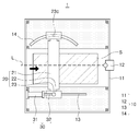
구체적으로 도면을 참조하여 설명하면, 도 1 및 도 2는 본 발명의 위치교정장치(1)를 도시한 평면도이며, 도 3은 본 발명의 위치교정장치(1)에 의해서 소재(S)의 센터링이 수행되는 상태를 도시한 평면도로서, 본 발명의 일 실시예에 따른 위치교정장치(1)는 소재(S)의 이동 경로 상에 배치되는 교정바디부(10), 상기 교정바디부(10)에 구비되며, 상기 소재(S)에 접하여 상기 소재(S)를 이동시키는 교정롤부(20) 및 상기 교정바디부(10)에 결합되고, 상기 교정롤부(20)의 일단부에 연결되어 상기 교정롤부(20)의 일단부를 밀거나 당겨서 상기 교정롤부(20)의 배치 각도를 조정하는 각도조정부(30)를 포함할 수 있다.Specifically, referring to the drawings, FIGS. 1 and 2 are plan views showing the
이와 같이, 본 발명의 위치교정장치(1)는 각도조정부(30)에 의해서 상기 교정롤부(20)의 배치 각도를 조정함에 의해서, 상기 교정롤부(20)에 의해서 이동되는 소재(S)의 전달 방향을 틸팅하여 소재(S)의 위치를 조정할 수 있게 된다.As described above, the
이에 따라 압연기(2) 등에서 소재(S)의 위치 조정을 위한 소재(S)의 폭 방향 양측에서의 압하력이 차이나도록 구동할 필요가 없어, 소재(S)의 압연 품질이 저하되는 문제를 방지할 수 있게 된다.Accordingly, there is no need to drive such that the rolling force of both sides in the width direction of the material S for adjusting the position of the material S in the
상기 교정바디부(10)는 상기 교정롤부(20), 각도조정부(30) 등의 몸체 역할을 하며, 상기 소재(S)의 이동 경로 상에 배치되어 상기 교정롤부(20), 각도조정부(30)에 의한 소재(S)의 위치를 조정할 수 있게 배치된다.The
이를 위해서, 상기 교정바디부(10)는 지지프레임(11) 등을 포함할 수 있다. 그리고, 상기 교정바디부(10)는 소재(S)의 위치를 계측하여 상기 교정롤부(20), 각도조정부(30) 등에 의한 소재(S)의 위치 조정 또는 소재(S)의 위치 조정 데이터를 수집하여 피드백에 의한 소재(S)의 위치 재조정으로 더욱 정밀한 제어를 수행하기 위한 계측카메라(12)가 구비될 수 있다. To this end, the
즉, 본 발명의 일 실시예에 따른 위치교정장치(1)의 상기 교정바디부(10)는, 상기 소재(S)의 이동 경로 상에 배치되는 지지프레임(11) 및 상기 지지프레임(11)에 구비되되, 상기 소재(S)가 배출되는 출측에 구비되고, 배출되는 소재(S)의 위치 데이터를 수집하는 계측카메라(12)를 포함할 수 있다.That is, the
여기서, 상기 계측카메라(12)가 상기 소재(S)가 배출되는 상기 지지프레임(11)의 출측에 배치되는 것은 상기 소재(S)의 위치가 정위치에서 벗어난 문제를 감지하는 것은 물론이고, 상기 교정롤부(20), 각도조정부(30) 등에 의한 소재(S)의 위치가 조정된 후의 결과를 감지도 할 수 있기 때문이다.Here, the
다시 말해, 상기 계측카메라(12)가 상기 소재(S)가 진입하는 상기 지지프레임(11)의 입측에 배치된다면 소재(S)의 위치가 정위치에서 벗어난 문제는 감지할 수 있으나, 상기 교정롤부(20), 각도조정부(30)에 의한 소재(S)의 위치 조정 결과 데이터의 수집은 할 수 없으나, 상기 계측카메라(12)가 상기 지지프레임(11)의 출측에 배치되면 이와 같은 조정 결과 데이터도 수집할 수 있는 것이다.In other words, if the
또한 상기 교정바디부(10)는 상기 각도조정부(30)에 의하여 상기 교정롤부(20)의 배치 위치가 틸팅될 때, 상기 교정롤부(20)의 위치 이동을 가이드하는 직선레일부재(13), 원호레일부재(14) 등을 포함할 수도 있다.In addition, the
즉, 본 발명의 일 실시예에 따른 위치교정장치(1)의 상기 교정바디부(10)는, 상기 소재(S)의 이동 경로 상에 배치되는 지지프레임(11), 상기 지지프레임(11)에 구비되되, 상기 교정롤부(20)의 일단부에 연계되며, 상기 각도조정부(30)에 의해서 직선 이동하는 상기 교정롤부(20)의 일단부의 이동을 가이드하는 직선레일부재(13) 및 상기 지지프레임(11)에 구비되되, 상기 교정롤부(20)의 타단부에 연계되며, 상기 교정롤부(20)의 일단부가 직선 이동됨에 따라 원호 방향 이동되는 상기 교정롤부(20)의 타단부의 이동을 가이드하는 원호레일부재(14)를 포함할 수 있다.That is, the
이와 같이 상기 직선레일부재(13)는 상기 각도조정부(30)가 직선 이동만을 수행하도록 유도하며, 이에 따라 상기 각도조정부(30)와 연결된 상기 교정롤부(20)의 일단부의 이동도 직선 이동만 하도록 가이드하게 된다.In this way, the
그리고, 상기 원호레일부재(14)는 상기 직선레일부재(13)에 의해서 상기 교정롤부(20)의 일단부가 직선 이동함에 따라 상기 교정롤부(20)의 타단부가 원호 방향으로 이동하는 것을 가이드하게 된다.In addition, the
다시 말해, 상기 교정롤부(20)는 강체(rigid body)이므로 상기 교정롤부(20)의 일단부가 직선 운동으로 위치 변경되면 상기 교정롤부(20)의 타단부도 위치가 이동되어야 한다. 이때 상기 교정롤부(20)는 상기 원호레일부재(14)에 형성된 원호홈부를 따라 이동되어야 하는데, 이의 방향은 상기 교정롤부(20)의 일단부가 밀려지거나 당겨지는 방향과 반대 방향이게 된다. 이에 따라 상기 교정롤부(20)는 일정 각도 경사진 방향으로 배치될 수 있게 되고, 상기 소재(S)도 이에 따라 위치가 조정되게 된다.In other words, since the
이를 위해서, 상기 직선레일부재(13)에는 직선홈부가 형성되고, 상기 원호레일부재(14)에는 원호홈부가 형성되며, 상기 교정롤부(20)의 베어링블럭(22)에는 상기 직선홈부 또는 상기 원호홈부에 안착되는 가이드탭(22c)이 하단부에 형성될 수 있다.To this end, a linear groove portion is formed in the
다만, 이와 같이 상기 각도조정부(30)에 결합된 상기 교정롤부(20)의 일단부가 직선 이동하게 결합되는 경우는 상기 각도조정부(30)가 지지프레임(11)에 고정된 실시예의 경우에 필요한 구성이다.However, when the one end portion of the
즉, 상기 각도조정부(30)가 상기 지지프레임(11)에 핀 결합되어 회전가능하게 결합되는 실시예의 경우에는 상기 각도조정부(30)가 결합된 상기 교정롤부(20)의 일단부는 직선 이동하는 것이 아니라 원호 방향 이동하게 되며, 이러한 경우에는 상기 각도조정부(30)가 연결된 상기 교정롤부(20)의 일단부 원호레일부재(14)에 의해서 원호 방향 이동으로 가이드되게 된다.That is, in the embodiment in which the
상기 교정롤부(20)는 상기 소재(S)에 접하여 상기 소재(S)를 이동시키는 역할을 하게 된다. 즉, 상기 교정롤부(20)는 상기 소재(S)에 접하며 회전되게 구비되어 상기 소재(S)를 이동시킬 수 있는 것이다.The straightening
그리고, 상기 교정롤부(20)는 상기 소재(S)를 이동시키는 경우에 상기 소재(S)를 중심에서 일정 각도 틸팅된 방향으로 이동시키기 위해서, 상기 각도조정부(30)에 의해서 경사지게 배치될 수 있다.In addition, the
이를 위해서, 상기 교정롤부(20)는 교정롤러(21), 베어링블럭(22), 회전핀부재(23) 등을 포함할 수 있다.To this end, the straightening
즉, 본 발명의 일 실시예에 따른 위치교정장치(1)의 상기 교정롤부(20)는, 상기 소재(S)에 접하여 상기 소재(S)를 이동시키는 교정롤러(21), 상기 교정바디부(10)에 연계되고, 상기 교정롤러(21)의 양단부에 각각 구비되어 상기 교정롤러(21)를 지지하는 베어링블럭(22) 및 상기 교정롤러(21)의 일단부에 구비되는 베어링블럭(22)에 회전되게 구비되고, 상기 각도조정부(30)의 신축하는 일단부가 결합되는 회전핀부재(23)를 포함할 수 있다.That is, the
상기 교정롤러(21)는 회전되게 구비되어 상기 소재(S)에 직접 접촉되어 상기 소재(S)를 이동시키는 역할을 하게 된다. 이를 위해서 상기 교정롤러(21)는 상부와 하부에 각각 배치될 수 있는데, 이에 대하 자세한 설명은 도 4를 참조하여 후술한다.The
상기 베어링블럭(22)은 상기 교정롤러(21)의 회전을 지지하고, 상기 교정바디부(10)에서 센터라인(L)을 기준으로 틸팅되게 상기 교정롤러(21)가 배치되도록 상기 각도조정부(30)와 연결되고, 상기 교정바디부(10)에 배치되는 구성이다.The bearing
이를 위해서, 상기 교정롤러(21)의 일단부에 구비되는 베어링블럭(22)은 상단부가 상기 각도조정부(30)의 신축봉부재(32)에 상기 회전핀부재(23)를 매개로 연결되며, 하단부는 상기 교정바디부(10)의 직선레일부재(13)의 직선홈부에 안착되는 가이드탭(22c)이 형성될 수 있다.To this end, the bearing
그리고, 상기 교정롤러(21)의 타단부에 구비되는 베어링블럭(22)은 하단부에 상기 교정바디부(10)의 원호레일부재(14)의 원호홈부에 안착되는 가이드탭(22c)이 형성될 수 있다.Then, the bearing
상기 회전핀부재(23)는 상기 각도조정부(30)에 의해서 상기 교정롤러(21)의 일단부에 구비되는 베어링블럭(22)이 밀려지거나 당겨지면서 상기 교정롤러(21)의 타단부가 센터라인(L)을 기준으로 틸팅되게 일정 각도로 회전될 때, 상기 각도조정부(30)와 상기 교정롤러(21)의 일단부에 구비되는 베어링블럭(22)의 회전 결합이 가능하도록 연결하는 역할을 하게 된다.The
이를 위해서 상기 회전핀부재(23)는 수직회전핀(23a), 이탈방지플랜지(23b)를 포함할 수 있는데, 이에 대한 자세한 설명은 도 5를 참조하여 후술한다.To this end, the
상기 각도조정부(30)는 상기 교정롤부(20)의 배치 위치를 센터라인(L)을 기준으로 틸팅시키는 역할을 하게 된다. 즉, 상기 각도조정부(30)는 상기 교정롤부(20)의 일단부만을 밀거나 당기게 구비됨에 의해서 상기 교정롤부(20)의 위치를 틸팅시키게 된다.The
여기서, 상기 각도조정부(30)가 상기 교정롤부(20)의 배치 위치를 조정하는 구동력은 유압 또는 공압의 실린더 수단일 수도 있고, 모터구동 스크류잭 등의 여러가지 액츄에이터를 활용할 수도 있다.Here, the driving force for the
일례로, 도 1에 도시된 바와 같이, 상기 각도조정부(30)는 일단부는 상기 지지프레임(11)에 핀 결합되어 회전가능하게 결합되고, 타단부는 상기 교정롤부(20)의 일단부와 회전가능하게 결합되게 구성되면, 상기 각도조정부(30)의 신축에 따라 상기 지지프레임(11)에 핀 결합된 상기 교정롤부(20)의 타단부는 회전축이 되어 상기 교정롤부(20)의 일단부를 원호 방향 이동시키며 배치 각도를 조정할 수 있게 된다.As an example, as shown in FIG. 1, the
이를 위해서, 상기 각도조정부(30)는 실린더바디(31), 신축봉부재(32) 등을 포함할 수 있다. 즉, 본 발명의 일 실시예에 따른 위치교정장치(1)의 상기 각도조정부(30)는, 상기 교정바디부(10)에 회전가능하게 핀 결합되는 실린더바디(31) 및 상기 실린더바디(31)에 신축하게 구비되고, 상기 교정롤부(20)의 일단부에 연결되어, 상기 교정롤부(20)의 일단부를 밀거나 당기게 구비된 신축봉부재(32)를 포함할 수 있다.To this end, the
또는, 상기 각도조정부(30)의 일단부는 상기 지지프레임(11)에 고정 결합되고, 타단부는 상기 교정롤부(20)의 일단부가 직선 이동하게 결합되어, 상기 교정롤부(20)의 타단부를 원호 방향 이동하게 구비되어 상기 교정롤부(20)의 배치 각도를 조정하게 구비될 수도 있다.Alternatively, one end of the
다시 말해, 상기 각도조정부(30)가 상기 교정롤부(20)의 일단부를 밀거나 당겨서 위치 변경하는 경우에도, 상기 교정롤부(20)의 타단부는 관성에 의해서 위치가 변경되려고 하지 않기 때문에, 결과적으로 상기 교정롤부(20)는 틸팅된 상태로 배치되게 된다.In other words, even when the
다만, 이러한 상기 교정롤부(20)의 틸팅 위치의 배치를 위해서 상기 교정바디부(10)의 직선레일부재(13), 원호레일부재(14) 등이 구비될 수 있다. However, for the arrangement of the tilting position of the
즉, 상기 각도조정부(30)가 상기 교정롤부(20)의 일단부를 밀거나 당기면 상기 직선레일부재(13)에 의해서 직선 이동만 하게 되고, 상기 원호레일부재(14)에 배치된 상기 교정롤부(20)의 타단부는 관성에 의해서 위치 고정하려고 하는데, 이때 상기 교정롤부(20)의 일단부가 이동하면 반발력에 의해서 강체인 상기 교정롤부(20)의 타단부는 그 반대 방향으로 이동되며, 이에 따라 상기 교정롤부(20)는 센터라인(L)을 기준으로 틸팅되게 배치되는 것이다.That is, when the
이와 같이 상기 각도조정부(30)에 연결된 상기 교정롤부(20)의 일단부가 직선 운동만 하므로, 상기 교정롤부(20)의 틸팅 위치 변경시에도 상기 각도조정부(30)는 밴딩되려는 반작용을 받지 않아 파손을 방지할 수 있고, 또한 직선 이동만을 고려하여 상기 교정롤부(20)의 틸팅 각도를 제어하므로 제어를 더욱 단순화할 수 있다.As described above, since the one end of the
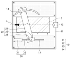
이러한 각도조정부(30)는 실린더바디(31), 신축봉부재(32) 등을 포함할 수 있다. 즉, 본 발명의 일 실시예에 따른 위치교정장치(1)의 상기 각도조정부(30)는, 상기 교정바디부(10)에 고정 결합되는 실린더바디(31) 및 상기 실린더바디(31)에 신축하게 구비되고, 상기 교정롤부(20)의 일단부에 연결되어, 상기 교정롤부(20)의 일단부를 상기 소재(S)의 이동 경로에 수평한 방향으로 직선 이동시키는 신축봉부재(32)를 포함할 수 있다.The
상기 실린더바디(31)는 상기 교정바디부(10)에 고정됨에 의해서 상기 신축봉부재(32)의 신축에 따른 신축 길이의 기준점이 된다. 그리고, 상기 신축봉부재(32)는 상기 교정롤부(20)의 일단부에 결합되어 상기 교정롤부(20)의 일단부만을 밀거나 당김에 의해서 상기 교정롤부(20)의 위치를 센터라인(L)을 기준으로 틸팅시키게 된다.The
도 4는 본 발명의 위치교정장치(1)를 도시한 측면도로서, 상기 도면을 참조하면, 본 발명의 일 실시예에 따른 위치교정장치(1)의 상기 교정롤러(21)는, 상기 소재(S)의 상하면에 한 쌍이 구비되도록, 상기 소재(S)의 상면에 접하는 상부롤러(21a)와, 상기 소재(S)의 하면에 접하는 하부롤러(21b)를 포함하는 것을 특징으로 할 수 있다.Figure 4 is a side view showing the
이와 같이 상기 교정롤러(21)가 상부롤러(21a), 하부롤러(21b)로 한 쌍이 구비됨에 의해서 상기 소재(S)의 위치 이동시에 상기 소재(S)의 상하면과 접하여 이동시키므로, 더욱 안정적으로 정확한 위치 조정을 하게 된다.As described above, since the
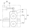
도 5는 본 발명의 위치교정장치(1)에서 회전핀부재(23) 부분의 단면을 도시한 측면도로서, 상기 도면을 참조하면, 본 발명의 일 실시예에 따른 위치교정장치(1)의 상기 회전핀부재(23)는, 상기 각도조정부(30)와 결합되는 수직회전핀(23a) 및 상기 수직회전핀(23a)의 하단부에 돌출되게 형성되고, 상기 베어링블럭(22)의 상부에 형성된 핀수용홀(22a)에 배치되는 이탈방지플랜지(23b)를 포함할 수 있다.Figure 5 is a side view showing a cross-section of a portion of the
즉, 상기 회전핀부재(23)는 상기 수직회전핀(23a), 이탈방지플랜지(23b)를 포함함에 의해서, 상기 각도조정부(30)에 의해서 상기 교정롤러(21)의 일단부에 구비되는 베어링블럭(22)이 밀려지거나 당겨지면서 상기 교정롤러(21)의 타단부가 틸팅되게 일정 각도로 회전될 때, 상기 각도조정부(30)와 상기 교정롤러(21)의 일단부에 구비되는 베어링블럭(22)의 회전 결합이 가능하도록 연결할 수 있게 된다.That is, the
다시 말해, 상기 교정롤부(20)의 틸팅을 위한 회전에 대한 회전축의 역할을 할 수 있도록 상기 수직회전핀(23a), 이탈방지플랜지(23b)를 포함하는 것이다.In other words, to include the
이와 같이 상기 수직회전핀(23a)의 하단부에 상기 이탈방지플랜지(23b)가 결합된 상태로 상기 교정롤러(21)의 일단부에 구비된 상기 베어링블럭(22)의 상단부에 형성된 핀수용홀(22a)에 수용됨으로서, 상기 수직회전핀(23a)은 상기 교정롤러(21)의 회전에 대한 회전축 역할을 하게 되는 것이다.As described above, the pin receiving hole formed at the upper end of the
더하여, 상기 핀수용홀(22a)의 외측에 인접한 상기 수직회전핀(23a)의 부분에 외측플랜지(23c)가 돌출되게 형성되어 상기 수직회전핀(23a)의 회전을 더욱 안정적으로 지지할 수도 있다.In addition, an
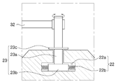
그리고, 본 발명의 일 실시예에 따른 위치교정장치(1)의 상기 이탈방지플랜지(23b)는, 상기 핀수용홀(22a)의 내측면 둘레 방향으로 탄성돌출되는 복수의 지지스프링(22b)에 의해서 지지되는 것을 특징으로 할 수 있다.In addition, the
이와 같이 상기 지지스프링(22b)이 상기 이탈방지플랜지(23b)의 둘레 방향으로 탄성적으로 지지함에 의해서, 상기 이탈방지플랜지(23b)는 상기 핀수용홀(22a) 내부에서도 가운데 부분에 위치할 수 있게 되고, 이에 따른 상기 수직회전핀(23a)의 위치 변동을 방지하게 된다. 이에 의해서 상기 교정롤러(21)의 틸팅 위치 제어시에 오차를 줄일 수 있어, 소재(S) 위치 조정의 신뢰도를 높일 수 있게 된다.As described above, the
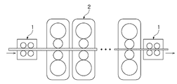
도 6은 본 발명의 압연설비를 도시한 측면도로서, 상기 도면을 참조하면, 본 발명의 다른 실시예에 따른 압연설비는 소재(S)의 이동 경로 상에 배치되어 상기 소재(S)를 압하여 두께를 감소시키는 압연기(2) 및 상기 소재(S)가 상기 압연기(2)로 진입하는 입측 및 상기 소재(S)가 상기 압연기(2)에서 배출되는 출측 중 적어도 하나의 위치에 배치되는 상기 위치교정장치(1)를 포함할 수 있다.Figure 6 is a side view showing the rolling equipment of the present invention, referring to the drawings, the rolling equipment according to another embodiment of the present invention is disposed on the movement path of the material (S) to press the material (S) The position in which at least one of the rolling
다시 말해, 상기 위치조정장치는 압연기(2)의 입측 및 출측 중 적어도 하나에 배치됨에 의해서, 압연 전의 소재(S) 또는 압연 후의 소재(S)에 대한 센터링을 수행하여 압연 제품의 품질을 향상시킬 수 있게 된다.In other words, the positioning device is arranged on at least one of the inlet and the outlet side of the rolling
이상에서 본 발명의 실시예에 대하여 설명하였지만 본 발명의 권리범위는 이에 한정되는 것은 아니고, 청구범위에 기재된 본 발명의 기술적 사상을 벗어나지 않는 범위 내에서 다양한 수정 및 변형이 가능하다는 것은 당 기술분야의 통상의 지식을 가진 자에게는 자명할 것이다.Although the embodiments of the present invention have been described above, the scope of the present invention is not limited to this, and it is possible in the art to make various modifications and variations without departing from the technical spirit of the present invention as set forth in the claims. It will be obvious to those with ordinary knowledge.
1: 위치교정장치
2: 압연기
10: 교정바디부
11: 지지프레임
12: 계측카메라
13: 직선레일부재
14: 원호레일부재
20: 교정롤부
21: 교정롤러
22: 베어링블럭
23: 회전핀부재
30: 각도조정부
31: 실린더바디
32: 신축봉부재1: Positioning device 2: Rolling machine
10: orthodontic body part 11: support frame
12: measurement camera 13: straight rail member
14: circular rail member 20: straightening roll portion
21: straightening roller 22: bearing block
23: rotating pin member 30: angle adjustment unit
31: cylinder body 32: telescopic rod member
Claims (10)
상기 교정바디부에 구비되며, 상기 소재에 접하여 상기 소재를 이동시키는 교정롤부; 및
상기 교정바디부에 결합되고, 상기 교정롤부의 일단부에 연결되어 상기 교정롤부의 일단부를 밀거나 당겨서 상기 교정롤부의 배치 각도를 조정하는 각도조정부;
를 포함하는 위치교정장치.A calibration body part disposed on a moving path of the material;
A calibration roll part provided on the calibration body part and moving the material in contact with the material; And
An angle adjusting unit coupled to the calibration body part and connected to one end of the calibration roll part to adjust an arrangement angle of the calibration roll part by pushing or pulling one end of the calibration roll part;
Position correction device comprising a.
상기 각도조정부는,
상기 교정바디부에 회전가능하게 핀 결합되는 실린더바디; 및
상기 실린더바디에 신축하게 구비되고, 상기 교정롤부의 일단부에 연결되어, 상기 교정롤부의 일단부를 밀거나 당기게 구비된 신축봉부재;
를 포함하는 위치교정장치.According to claim 1,
The angle adjustment unit,
A cylinder body rotatably pin-coupled to the calibration body portion; And
A telescopic rod member which is elastically provided on the cylinder body, connected to one end of the straightening roll portion, and pushed or pulled at one end of the straightening roll portion;
Position correction device comprising a.
상기 각도조정부는,
상기 교정바디부에 고정 결합되는 실린더바디; 및
상기 실린더바디에 신축하게 구비되고, 상기 교정롤부의 일단부에 연결되어, 상기 교정롤부의 일단부를 상기 소재의 이동 경로에 수평한 방향으로 직선 이동시키는 신축봉부재;
를 포함하는 위치교정장치.According to claim 1,
The angle adjustment unit,
A cylinder body fixedly coupled to the calibration body portion; And
A telescopic rod member which is elastically provided on the cylinder body, is connected to one end of the straightening roll portion, and linearly moves one end of the straightening roll portion in a horizontal direction to the movement path of the material;
Position correction device comprising a.
상기 교정롤부는,
상기 소재에 접하여 상기 소재를 이동시키는 교정롤러;
상기 교정바디부에 연계되고, 상기 교정롤러의 양단부에 각각 구비되어 상기 교정롤러를 지지하는 베어링블럭; 및
상기 교정롤러의 일단부에 구비되는 베어링블럭에 회전되게 구비되고, 상기 각도조정부의 신축하는 일단부가 결합되는 회전핀부재;
를 포함하는 위치교정장치.According to claim 1,
The correction roll portion,
A calibration roller that moves the material in contact with the material;
A bearing block connected to the calibration body part and provided at both ends of the calibration roller to support the calibration roller; And
A rotating pin member provided to be rotated in a bearing block provided at one end of the straightening roller, and coupled to an elastic end of the angle adjusting unit;
Position correction device comprising a.
상기 회전핀부재는,
상기 각도조정부와 결합되는 수직회전핀; 및
상기 수직회전핀의 하단부에 돌출되게 형성되고, 상기 베어링블럭의 상부에 형성된 핀수용홀에 배치되는 이탈방지플랜지;
를 포함하는 위치교정장치.The method of claim 4,
The rotating pin member,
A vertical rotation pin coupled with the angle adjustment unit; And
A departure preventing flange formed to protrude at the lower end of the vertical rotating pin and disposed in a pin receiving hole formed on an upper portion of the bearing block;
Position correction device comprising a.
상기 이탈방지플랜지는, 상기 핀수용홀의 내측면 둘레 방향으로 탄성돌출되는 복수의 지지스프링에 의해서 지지되는 것을 특징으로 하는 위치교정장치.The method of claim 5,
The departure prevention flange, position correction device, characterized in that supported by a plurality of support springs elastically projecting in the circumferential direction of the inner surface of the pin receiving hole.
상기 교정롤러는, 상기 소재의 상하면에 한 쌍이 구비되도록, 상기 소재의 상면에 접하는 상부롤러와, 상기 소재의 하면에 접하는 하부롤러를 포함하는 것을 특징으로 하는 위치교정장치.The method of claim 4,
The calibration roller, the position correction device, characterized in that it comprises a pair of upper and lower rollers in contact with the upper surface of the material, the lower roller contacting the lower surface of the material so that a pair is provided on the upper and lower surfaces of the material.
상기 교정바디부는,
상기 소재의 이동 경로 상에 배치되는 지지프레임; 및
상기 지지프레임에 구비되되, 상기 소재가 배출되는 출측에 구비되고, 배출되는 소재의 위치 데이터를 수집하는 계측카메라;
를 포함하는 위치교정장치.According to claim 1,
The correction body portion,
A support frame disposed on the movement path of the material; And
A measurement camera provided on the support frame, provided on the discharge side where the material is discharged, and collecting location data of the discharged material;
Position correction device comprising a.
상기 교정바디부는,
상기 소재의 이동 경로 상에 배치되는 지지프레임;
상기 지지프레임에 구비되되, 상기 교정롤부의 일단부에 연계되며, 상기 각도조정부에 의해서 직선 이동하는 상기 교정롤부의 일단부의 이동을 가이드하는 직선레일부재; 및
상기 지지프레임에 구비되되, 상기 교정롤부의 타단부에 연계되며, 상기 교정롤부의 일단부가 직선 이동됨에 따라 원호 방향 이동되는 상기 교정롤부의 타단부의 이동을 가이드하는 원호레일부재;
를 포함하는 위치교정장치.According to claim 3,
The correction body portion,
A support frame disposed on the movement path of the material;
A straight rail member provided in the support frame, connected to one end of the straightening roll portion, and guiding movement of one end of the straightening roll portion linearly moved by the angle adjusting unit; And
A circular rail member provided in the support frame, connected to the other end of the straightening roll portion, and guiding the movement of the other end of the straightening roll portion moving in an arc direction as one end portion of the straightening roll portion moves linearly;
Position correction device comprising a.
상기 소재가 상기 압연기로 진입하는 입측 및 상기 소재가 상기 압연기에서 배출되는 출측 중 적어도 하나의 위치에 배치되는 제1항 내지 제9항 중 어느 한 항의 위치교정장치;
를 포함하는 압연설비.A rolling mill disposed on a moving path of the material to reduce the thickness by pressing the material; And
A position correction device according to any one of claims 1 to 9, wherein the material enters the rolling mill and is disposed at at least one of an exit side from which the material exits the rolling mill;
Rolling equipment comprising a.
Priority Applications (1)
| Application Number | Priority Date | Filing Date | Title |
|---|---|---|---|
| KR1020180151370A KR102164122B1 (en) | 2018-11-29 | 2018-11-29 | Position adjusting apparatus and rolling facility having thereof |
Applications Claiming Priority (1)
| Application Number | Priority Date | Filing Date | Title |
|---|---|---|---|
| KR1020180151370A KR102164122B1 (en) | 2018-11-29 | 2018-11-29 | Position adjusting apparatus and rolling facility having thereof |
Publications (2)
| Publication Number | Publication Date |
|---|---|
| KR20200064813A true KR20200064813A (en) | 2020-06-08 |
| KR102164122B1 KR102164122B1 (en) | 2020-10-12 |
Family
ID=71089710
Family Applications (1)
| Application Number | Title | Priority Date | Filing Date |
|---|---|---|---|
| KR1020180151370A KR102164122B1 (en) | 2018-11-29 | 2018-11-29 | Position adjusting apparatus and rolling facility having thereof |
Country Status (1)
| Country | Link |
|---|---|
| KR (1) | KR102164122B1 (en) |
Citations (15)
| Publication number | Priority date | Publication date | Assignee | Title |
|---|---|---|---|---|
| JPS59179210A (en) * | 1983-03-31 | 1984-10-11 | Ishikawajima Harima Heavy Ind Co Ltd | Device for turning direction of strip |
| JPS61203059A (en) * | 1985-03-01 | 1986-09-08 | Mitsubishi Heavy Ind Ltd | Device of correcting meandering of band plate |
| JPH03189011A (en) * | 1989-12-18 | 1991-08-19 | Ishikawajima Harima Heavy Ind Co Ltd | Meanderings controller for feeding side of finishing mill |
| JPH07251215A (en) * | 1994-03-16 | 1995-10-03 | Sumitomo Metal Ind Ltd | Pinch roll for correcting meandering of strip, device for correcting meandering and method therefor |
| JPH07256327A (en) * | 1994-03-18 | 1995-10-09 | Sumitomo Metal Ind Ltd | Pinch roll for correcting meandering of strip, device and method for correcting meandering |
| KR19990052504A (en) * | 1997-12-22 | 1999-07-15 | 이구택 | High temperature wire meandering device |
| KR19990031918U (en) * | 1997-12-31 | 1999-07-26 | 정몽규 | Split Piston Pin |
| KR20050007493A (en) * | 2003-07-08 | 2005-01-19 | 주식회사 포스코 | Apparatus for controlling strip in roll |
| JP2005131687A (en) * | 2003-10-31 | 2005-05-26 | Jfe Steel Kk | Roll having uneven cross-sectional shape for pinching metallic sheet, method for straightening shape of metallic sheet, welding method and continuous processing line for metallic sheet using the same |
| KR20100105603A (en) | 2007-12-21 | 2010-09-29 | 킴벌리-클라크 월드와이드, 인크. | Gas treatment system |
| KR200451356Y1 (en) * | 2008-04-03 | 2010-12-10 | 주식회사 제일테크노쎌 | Plate leveller |
| KR20130114293A (en) * | 2012-04-09 | 2013-10-17 | 김광열 | Leveler |
| KR20140028660A (en) * | 2012-08-30 | 2014-03-10 | 현대제철 주식회사 | Apparatus for meandering correction of material |
| KR20140084661A (en) * | 2012-12-27 | 2014-07-07 | 주식회사 포스코 | Apparatus for leveling hot plate |
| KR101516593B1 (en) * | 2013-12-23 | 2015-05-04 | 주식회사 포스코 | Apparatus and method for adjusting skewness of steel plate in cooling bed |
-
2018
- 2018-11-29 KR KR1020180151370A patent/KR102164122B1/en active IP Right Grant
Patent Citations (15)
| Publication number | Priority date | Publication date | Assignee | Title |
|---|---|---|---|---|
| JPS59179210A (en) * | 1983-03-31 | 1984-10-11 | Ishikawajima Harima Heavy Ind Co Ltd | Device for turning direction of strip |
| JPS61203059A (en) * | 1985-03-01 | 1986-09-08 | Mitsubishi Heavy Ind Ltd | Device of correcting meandering of band plate |
| JPH03189011A (en) * | 1989-12-18 | 1991-08-19 | Ishikawajima Harima Heavy Ind Co Ltd | Meanderings controller for feeding side of finishing mill |
| JPH07251215A (en) * | 1994-03-16 | 1995-10-03 | Sumitomo Metal Ind Ltd | Pinch roll for correcting meandering of strip, device for correcting meandering and method therefor |
| JPH07256327A (en) * | 1994-03-18 | 1995-10-09 | Sumitomo Metal Ind Ltd | Pinch roll for correcting meandering of strip, device and method for correcting meandering |
| KR19990052504A (en) * | 1997-12-22 | 1999-07-15 | 이구택 | High temperature wire meandering device |
| KR19990031918U (en) * | 1997-12-31 | 1999-07-26 | 정몽규 | Split Piston Pin |
| KR20050007493A (en) * | 2003-07-08 | 2005-01-19 | 주식회사 포스코 | Apparatus for controlling strip in roll |
| JP2005131687A (en) * | 2003-10-31 | 2005-05-26 | Jfe Steel Kk | Roll having uneven cross-sectional shape for pinching metallic sheet, method for straightening shape of metallic sheet, welding method and continuous processing line for metallic sheet using the same |
| KR20100105603A (en) | 2007-12-21 | 2010-09-29 | 킴벌리-클라크 월드와이드, 인크. | Gas treatment system |
| KR200451356Y1 (en) * | 2008-04-03 | 2010-12-10 | 주식회사 제일테크노쎌 | Plate leveller |
| KR20130114293A (en) * | 2012-04-09 | 2013-10-17 | 김광열 | Leveler |
| KR20140028660A (en) * | 2012-08-30 | 2014-03-10 | 현대제철 주식회사 | Apparatus for meandering correction of material |
| KR20140084661A (en) * | 2012-12-27 | 2014-07-07 | 주식회사 포스코 | Apparatus for leveling hot plate |
| KR101516593B1 (en) * | 2013-12-23 | 2015-05-04 | 주식회사 포스코 | Apparatus and method for adjusting skewness of steel plate in cooling bed |
Also Published As
| Publication number | Publication date |
|---|---|
| KR102164122B1 (en) | 2020-10-12 |
Similar Documents
| Publication | Publication Date | Title |
|---|---|---|
| JP4734181B2 (en) | Steel strip steering device | |
| US5226577A (en) | Web guide for elongated flexible web | |
| KR20200064813A (en) | Position adjusting apparatus and rolling facility having thereof | |
| US3966105A (en) | Web aligning apparatus | |
| JP2020518455A (en) | Device and method for guiding metal products | |
| US20210001388A1 (en) | Rolling mill and method of controlling the same | |
| US9433985B2 (en) | Feed roll assembly | |
| JPH11319950A (en) | Apparatus for straightening shape steel | |
| EP0493775B1 (en) | Guide device for shape rolling | |
| KR101627601B1 (en) | Apparatus for forming curved surface in metal plates | |
| US5699898A (en) | Apparatus for adjusting one of the bearing blocks of a roller | |
| JP5441421B2 (en) | Method and apparatus for correcting meander in continuous steel strip process line | |
| KR200189822Y1 (en) | Leveller adjusting cap of rolls easily | |
| JPH01197011A (en) | Apparatus for measuring outer diameter of pipe and straightening bend | |
| KR100646627B1 (en) | Continuous casting machine segment for controlling linear gap between rolls | |
| KR20200142838A (en) | Vertical strip accumulator | |
| JP2015202515A (en) | Corrector and steel plate correction method | |
| KR101852947B1 (en) | Dancer system | |
| KR100775230B1 (en) | Up-loop apparatus for preventing wire rod from waving | |
| JPH09248628A (en) | Roller straightening machine with automatic zero-point adjusting system | |
| KR101332780B1 (en) | Idle straightening apparatus for regulating angle of steel | |
| KR20010062790A (en) | Calibrating method for a universal roll stand | |
| ITMI940293A1 (en) | TWO-CYLINDER OBLIQUE ROLLER WITH GUIDE DISCS | |
| JP4621697B2 (en) | Eccentric link type rolling mill guide device | |
| KR20030006835A (en) | Device for revising the position of strip into the furnace |
Legal Events
| Date | Code | Title | Description |
|---|---|---|---|
| E701 | Decision to grant or registration of patent right | ||
| GRNT | Written decision to grant |