KR20200058454A - Plasma arc torch head, laser cutting head and plasma laser cutting head, nozzle for assembly, plasma arc torch head, plasma arc torch including the same, laser cutting head including the same, and plasma laser cutting head including the same - Google Patents
Plasma arc torch head, laser cutting head and plasma laser cutting head, nozzle for assembly, plasma arc torch head, plasma arc torch including the same, laser cutting head including the same, and plasma laser cutting head including the same Download PDFInfo
- Publication number
- KR20200058454A KR20200058454A KR1020207010851A KR20207010851A KR20200058454A KR 20200058454 A KR20200058454 A KR 20200058454A KR 1020207010851 A KR1020207010851 A KR 1020207010851A KR 20207010851 A KR20207010851 A KR 20207010851A KR 20200058454 A KR20200058454 A KR 20200058454A
- Authority
- KR
- South Korea
- Prior art keywords
- nozzle
- longitudinal axis
- plasma
- diameter
- laser cutting
- Prior art date
Links
- 238000003698 laser cutting Methods 0.000 title claims abstract description 52
- 238000005520 cutting process Methods 0.000 claims abstract description 47
- 238000000034 method Methods 0.000 claims abstract description 30
- 230000001681 protective effect Effects 0.000 claims abstract description 18
- 230000007704 transition Effects 0.000 claims description 43
- 230000008569 process Effects 0.000 claims description 11
- 230000001590 oxidative effect Effects 0.000 claims description 7
- 239000000203 mixture Substances 0.000 claims description 6
- 238000002955 isolation Methods 0.000 claims 1
- 239000007789 gas Substances 0.000 description 121
- 239000000463 material Substances 0.000 description 13
- 239000002826 coolant Substances 0.000 description 10
- 229910052751 metal Inorganic materials 0.000 description 8
- 239000002184 metal Substances 0.000 description 8
- XEEYBQQBJWHFJM-UHFFFAOYSA-N Iron Chemical compound [Fe] XEEYBQQBJWHFJM-UHFFFAOYSA-N 0.000 description 6
- 239000007788 liquid Substances 0.000 description 6
- 238000002360 preparation method Methods 0.000 description 6
- 229910052782 aluminium Inorganic materials 0.000 description 4
- XAGFODPZIPBFFR-UHFFFAOYSA-N aluminium Chemical compound [Al] XAGFODPZIPBFFR-UHFFFAOYSA-N 0.000 description 4
- 238000001816 cooling Methods 0.000 description 4
- RYGMFSIKBFXOCR-UHFFFAOYSA-N Copper Chemical compound [Cu] RYGMFSIKBFXOCR-UHFFFAOYSA-N 0.000 description 3
- BQCADISMDOOEFD-UHFFFAOYSA-N Silver Chemical compound [Ag] BQCADISMDOOEFD-UHFFFAOYSA-N 0.000 description 3
- ATJFFYVFTNAWJD-UHFFFAOYSA-N Tin Chemical compound [Sn] ATJFFYVFTNAWJD-UHFFFAOYSA-N 0.000 description 3
- HCHKCACWOHOZIP-UHFFFAOYSA-N Zinc Chemical compound [Zn] HCHKCACWOHOZIP-UHFFFAOYSA-N 0.000 description 3
- 229910045601 alloy Inorganic materials 0.000 description 3
- 239000000956 alloy Substances 0.000 description 3
- 229910052802 copper Inorganic materials 0.000 description 3
- 239000010949 copper Substances 0.000 description 3
- 229910052742 iron Inorganic materials 0.000 description 3
- 150000002739 metals Chemical class 0.000 description 3
- 229910052709 silver Inorganic materials 0.000 description 3
- 239000004332 silver Substances 0.000 description 3
- 238000005507 spraying Methods 0.000 description 3
- 239000011135 tin Substances 0.000 description 3
- 229910052718 tin Inorganic materials 0.000 description 3
- 229910052725 zinc Inorganic materials 0.000 description 3
- 239000011701 zinc Substances 0.000 description 3
- XKRFYHLGVUSROY-UHFFFAOYSA-N Argon Chemical compound [Ar] XKRFYHLGVUSROY-UHFFFAOYSA-N 0.000 description 2
- IJGRMHOSHXDMSA-UHFFFAOYSA-N Atomic nitrogen Chemical compound N#N IJGRMHOSHXDMSA-UHFFFAOYSA-N 0.000 description 2
- 229910000831 Steel Inorganic materials 0.000 description 2
- QVGXLLKOCUKJST-UHFFFAOYSA-N atomic oxygen Chemical compound [O] QVGXLLKOCUKJST-UHFFFAOYSA-N 0.000 description 2
- 239000000470 constituent Substances 0.000 description 2
- -1 ferrous metals Chemical class 0.000 description 2
- 230000004927 fusion Effects 0.000 description 2
- 230000036541 health Effects 0.000 description 2
- 238000002844 melting Methods 0.000 description 2
- 230000008018 melting Effects 0.000 description 2
- 230000003287 optical effect Effects 0.000 description 2
- 239000001301 oxygen Substances 0.000 description 2
- 229910052760 oxygen Inorganic materials 0.000 description 2
- 238000000926 separation method Methods 0.000 description 2
- 239000007921 spray Substances 0.000 description 2
- 239000010959 steel Substances 0.000 description 2
- 229910000851 Alloy steel Inorganic materials 0.000 description 1
- QCWXUUIWCKQGHC-UHFFFAOYSA-N Zirconium Chemical compound [Zr] QCWXUUIWCKQGHC-UHFFFAOYSA-N 0.000 description 1
- 230000009471 action Effects 0.000 description 1
- 230000002411 adverse Effects 0.000 description 1
- 239000003570 air Substances 0.000 description 1
- 229910052786 argon Inorganic materials 0.000 description 1
- 230000002238 attenuated effect Effects 0.000 description 1
- 238000002485 combustion reaction Methods 0.000 description 1
- 239000004020 conductor Substances 0.000 description 1
- 230000008602 contraction Effects 0.000 description 1
- 239000000110 cooling liquid Substances 0.000 description 1
- 230000001419 dependent effect Effects 0.000 description 1
- 230000001627 detrimental effect Effects 0.000 description 1
- 239000012777 electrically insulating material Substances 0.000 description 1
- 230000001747 exhibiting effect Effects 0.000 description 1
- 229910052735 hafnium Inorganic materials 0.000 description 1
- VBJZVLUMGGDVMO-UHFFFAOYSA-N hafnium atom Chemical compound [Hf] VBJZVLUMGGDVMO-UHFFFAOYSA-N 0.000 description 1
- 238000010438 heat treatment Methods 0.000 description 1
- 239000001307 helium Substances 0.000 description 1
- 229910052734 helium Inorganic materials 0.000 description 1
- SWQJXJOGLNCZEY-UHFFFAOYSA-N helium atom Chemical compound [He] SWQJXJOGLNCZEY-UHFFFAOYSA-N 0.000 description 1
- 239000001257 hydrogen Substances 0.000 description 1
- 229910052739 hydrogen Inorganic materials 0.000 description 1
- 125000004435 hydrogen atom Chemical class [H]* 0.000 description 1
- 239000000155 melt Substances 0.000 description 1
- DOTMOQHOJINYBL-UHFFFAOYSA-N molecular nitrogen;molecular oxygen Chemical compound N#N.O=O DOTMOQHOJINYBL-UHFFFAOYSA-N 0.000 description 1
- 229910052757 nitrogen Inorganic materials 0.000 description 1
- 230000008707 rearrangement Effects 0.000 description 1
- 230000009467 reduction Effects 0.000 description 1
- 238000007789 sealing Methods 0.000 description 1
- 238000004904 shortening Methods 0.000 description 1
- WFKWXMTUELFFGS-UHFFFAOYSA-N tungsten Chemical compound [W] WFKWXMTUELFFGS-UHFFFAOYSA-N 0.000 description 1
- 229910052721 tungsten Inorganic materials 0.000 description 1
- 239000010937 tungsten Substances 0.000 description 1
- XLYOFNOQVPJJNP-UHFFFAOYSA-N water Substances O XLYOFNOQVPJJNP-UHFFFAOYSA-N 0.000 description 1
- 229910052726 zirconium Inorganic materials 0.000 description 1
Images


Classifications
-
- H—ELECTRICITY
- H05—ELECTRIC TECHNIQUES NOT OTHERWISE PROVIDED FOR
- H05H—PLASMA TECHNIQUE; PRODUCTION OF ACCELERATED ELECTRICALLY-CHARGED PARTICLES OR OF NEUTRONS; PRODUCTION OR ACCELERATION OF NEUTRAL MOLECULAR OR ATOMIC BEAMS
- H05H1/00—Generating plasma; Handling plasma
- H05H1/24—Generating plasma
- H05H1/26—Plasma torches
- H05H1/32—Plasma torches using an arc
- H05H1/34—Details, e.g. electrodes, nozzles
- H05H1/3405—Arrangements for stabilising or constricting the arc, e.g. by an additional gas flow
-
- H—ELECTRICITY
- H05—ELECTRIC TECHNIQUES NOT OTHERWISE PROVIDED FOR
- H05H—PLASMA TECHNIQUE; PRODUCTION OF ACCELERATED ELECTRICALLY-CHARGED PARTICLES OR OF NEUTRONS; PRODUCTION OR ACCELERATION OF NEUTRAL MOLECULAR OR ATOMIC BEAMS
- H05H1/00—Generating plasma; Handling plasma
- H05H1/24—Generating plasma
- H05H1/26—Plasma torches
- H05H1/32—Plasma torches using an arc
- H05H1/34—Details, e.g. electrodes, nozzles
-
- B—PERFORMING OPERATIONS; TRANSPORTING
- B23—MACHINE TOOLS; METAL-WORKING NOT OTHERWISE PROVIDED FOR
- B23K—SOLDERING OR UNSOLDERING; WELDING; CLADDING OR PLATING BY SOLDERING OR WELDING; CUTTING BY APPLYING HEAT LOCALLY, e.g. FLAME CUTTING; WORKING BY LASER BEAM
- B23K10/00—Welding or cutting by means of a plasma
- B23K10/02—Plasma welding
-
- B—PERFORMING OPERATIONS; TRANSPORTING
- B23—MACHINE TOOLS; METAL-WORKING NOT OTHERWISE PROVIDED FOR
- B23K—SOLDERING OR UNSOLDERING; WELDING; CLADDING OR PLATING BY SOLDERING OR WELDING; CUTTING BY APPLYING HEAT LOCALLY, e.g. FLAME CUTTING; WORKING BY LASER BEAM
- B23K26/00—Working by laser beam, e.g. welding, cutting or boring
- B23K26/14—Working by laser beam, e.g. welding, cutting or boring using a fluid stream, e.g. a jet of gas, in conjunction with the laser beam; Nozzles therefor
- B23K26/1462—Nozzles; Features related to nozzles
-
- B—PERFORMING OPERATIONS; TRANSPORTING
- B23—MACHINE TOOLS; METAL-WORKING NOT OTHERWISE PROVIDED FOR
- B23K—SOLDERING OR UNSOLDERING; WELDING; CLADDING OR PLATING BY SOLDERING OR WELDING; CUTTING BY APPLYING HEAT LOCALLY, e.g. FLAME CUTTING; WORKING BY LASER BEAM
- B23K26/00—Working by laser beam, e.g. welding, cutting or boring
- B23K26/36—Removing material
- B23K26/38—Removing material by boring or cutting
-
- H—ELECTRICITY
- H05—ELECTRIC TECHNIQUES NOT OTHERWISE PROVIDED FOR
- H05H—PLASMA TECHNIQUE; PRODUCTION OF ACCELERATED ELECTRICALLY-CHARGED PARTICLES OR OF NEUTRONS; PRODUCTION OR ACCELERATION OF NEUTRAL MOLECULAR OR ATOMIC BEAMS
- H05H1/00—Generating plasma; Handling plasma
- H05H1/24—Generating plasma
- H05H1/26—Plasma torches
- H05H1/32—Plasma torches using an arc
- H05H1/34—Details, e.g. electrodes, nozzles
- H05H1/3484—Convergent-divergent nozzles
-
- H—ELECTRICITY
- H05—ELECTRIC TECHNIQUES NOT OTHERWISE PROVIDED FOR
- H05H—PLASMA TECHNIQUE; PRODUCTION OF ACCELERATED ELECTRICALLY-CHARGED PARTICLES OR OF NEUTRONS; PRODUCTION OR ACCELERATION OF NEUTRAL MOLECULAR OR ATOMIC BEAMS
- H05H1/00—Generating plasma; Handling plasma
- H05H1/24—Generating plasma
- H05H1/26—Plasma torches
- H05H1/32—Plasma torches using an arc
- H05H1/34—Details, e.g. electrodes, nozzles
- H05H1/3421—Transferred arc or pilot arc mode
-
- H—ELECTRICITY
- H05—ELECTRIC TECHNIQUES NOT OTHERWISE PROVIDED FOR
- H05H—PLASMA TECHNIQUE; PRODUCTION OF ACCELERATED ELECTRICALLY-CHARGED PARTICLES OR OF NEUTRONS; PRODUCTION OR ACCELERATION OF NEUTRAL MOLECULAR OR ATOMIC BEAMS
- H05H1/00—Generating plasma; Handling plasma
- H05H1/24—Generating plasma
- H05H1/26—Plasma torches
- H05H1/32—Plasma torches using an arc
- H05H1/34—Details, e.g. electrodes, nozzles
- H05H1/3478—Geometrical details
-
- H05H2001/3478—
-
- H05H2001/3484—
Landscapes
- Engineering & Computer Science (AREA)
- Physics & Mathematics (AREA)
- Plasma & Fusion (AREA)
- Spectroscopy & Molecular Physics (AREA)
- Mechanical Engineering (AREA)
- Optics & Photonics (AREA)
- Geometry (AREA)
- Plasma Technology (AREA)
- Arc Welding In General (AREA)
- Laser Beam Processing (AREA)
Abstract
플라즈마 토치 헤드, 레이저 절단 헤드 또는 플라즈마 레이저 절단 헤드용 노즐, 이러한 노즐 및 노즐 보호 캡으로 구성된 장치, 이러한 노즐 및 전극으로 구성된 장치, 이러한 노즐 및/또는 이러한 장치를 가지는 플라즈마 토치 헤드, 레이저 절단 헤드 또는 플라즈마 레이저 절단 헤드, 이러한 플라즈마 토치 헤드를 포함하는 플라즈마 토치, 이러한 노즐 및/또는 그러한 장치를 포함하는 레이저 절단 헤드, 이러한 노즐 및/또는 이러한 장치를 포함하는 플라즈마 레이저 절단 헤드, 이러한 것을 사용하는 플라즈마 절단 방법, 레이저 절단 방법, 및 플라즈마 레이저 절단 방법이 개시된다.Plasma torch heads, nozzles for laser cutting heads or plasma laser cutting heads, devices consisting of these nozzles and nozzle protective caps, devices consisting of such nozzles and electrodes, plasma torch heads having such nozzles and / or devices, laser cutting heads or Plasma laser cutting head, plasma torch including such a plasma torch head, laser cutting head including such a nozzle and / or such device, plasma laser cutting head including such a nozzle and / or such device, plasma cutting using the same Methods, laser cutting methods, and plasma laser cutting methods are disclosed.
Description
본 발명은 플라즈마 아크 토치 헤드, 레이저 절단 헤드 및 플라즈마 레이저 절단 헤드, 조립체를 위한 노즐, 플라즈마 아크 토치 헤드, 이를 포함하는 플라즈마 아크 토치, 이를 포함하는 레이저 절단 헤드, 및 이를 포함하는 플라즈마 레이저 절단 헤드에 관한 것이다.The present invention relates to a plasma arc torch head, a laser cutting head and a plasma laser cutting head, a nozzle for assembly, a plasma arc torch head, a plasma arc torch comprising the same, a laser cutting head comprising the same, and a plasma laser cutting head including the same. It is about.
플라즈마 토치, 레이저 절단 헤드 및 플라즈마 레이저 절단 헤드는 강 및 비철 금속과 같은 전기 전도성 재료의 열 처리에 매우 일반적으로 사용된다.Plasma torches, laser cutting heads and plasma laser cutting heads are very commonly used for heat treatment of electrically conductive materials such as steel and non-ferrous metals.
플라즈마 토치는 통상적으로 토치 바디, 전극, 노즐 및 이를 위한 브래킷으로 구성된다. 최신 플라즈마 토치는 추가적으로 노즐 위에 끼워지는 노즐 보호 캡을 가진다. 노즐은 종종 노즐 캡에 의해 고정된다.Plasma torches typically consist of a torch body, an electrode, a nozzle and a bracket therefor. Modern plasma torches additionally have a nozzle protection cap that fits over the nozzle. The nozzle is often fixed by a nozzle cap.
플라즈마 토치의 유형에 의존하여, 아크에 의해 유발되는 높은 열부하로 인한 플라즈마 토치의 작동의 결과로서 마모되는 구성 요소는 특히 전극, 노즐, 노즐 캡, 노즐 보호 캡, 노즐 보호 캡 브래킷, 및 플라즈마 가스 전도 유닛 및 2차 가스 전도 유닛 부품이다. 이들 구성 요소는 작업자에 의해 용이하게 교환될 수 있고, 그러므로 마모 부품으로서 지칭된다.Depending on the type of plasma torch, the components that wear out as a result of the operation of the plasma torch due to the high heat load caused by the arc are particularly electrodes, nozzles, nozzle caps, nozzle protection caps, nozzle protection cap brackets, and plasma gas conduction Unit and secondary gas conduction unit parts. These components can be easily exchanged by the operator and are therefore referred to as wear parts.
플라즈마 토치는 라인을 통해, 플라즈마 토치에 공급을 제공하는 전력 공급원 및 가스 공급원에 연결된다. 또한, 플라즈마 토치는 냉각액과 같은 냉각 매체를 위한 냉각 디바이스에 연결될 수 있다.The plasma torch is connected via a line to a gas supply and a power source that provides a supply to the plasma torch. In addition, the plasma torch can be connected to a cooling device for a cooling medium, such as a cooling liquid.
높은 열 부하가 플라즈마 절단 토치에서 마주친다. 이는 노즐 보어를 통한 플라즈마 제트의 강한 수축에 의해 유발된다. 여기에서, 노즐 보어에 있는 50 내지 150 A/㎟의 높은 전류 밀도, 약 2 x 10⁶ W/㎠의 높은 에너지 밀도, 및 최대 30 000 K의 높은 온도가 발생되도록 하기 위해 작은 보어들이 사용된다. 또한, 일반적으로 최대 12 bar의 비교적 높은 가스 압력이 플라즈마 절단 토치에서 사용된다. 노즐 보어를 통해 흐르는 플라즈마 가스의 높은 온도 및 높은 운동 에너지의 조합은 공작물의 용융 및 용융물의 배출로 이어진다. 절단(kerf)이 형성되어 공작물이 절단된다. 노즐에서의 절단 전류 및 전류 밀도와 사용된 가스에 의존하여, 플라즈마 제트가 노즐 및/또는 노즐 보호 캡으로부터 나옴에 따라서, 높은 레벨의 소음 공해가 발생한다. 이것은 100 ㏈(A)를 초과할 수 있다. 인간이 인식할 수 있는 소리 주파수는 대략 20 ㎐ 내지 대략 20000 ㎐의 범위에 있다. 진폭이 큰 고주파(> 1000 ㎐)는 불쾌한 것으로 인식될뿐만 아니라, 적절한 보호 수단이 사용되지 않으면 건강에 악영향을 미칠 수 있다. 플라즈마 절단 동안 소리의 주파수를 기록하면, 1000 ㎐ 내지 15,000 ㎐의 상당한 진폭이 관찰된다.A high thermal load is encountered in the plasma cutting torch. This is caused by the strong contraction of the plasma jet through the nozzle bore. Here, small bores are used to generate high current densities of 50 to 150 A /
플라즈마 절단에서, 비 합금 또는 저 합금강을 절단하기 위해 산화 가스가, 그리고 고 합금강 또는 비철 금속을 절단하기 위해 비산화 가스가 종종 사용된다.In plasma cutting, oxidizing gas is often used to cut non-alloyed or low-alloyed steel, and non-oxidized gas is used to cut high-alloyed or non-ferrous metals.
플라즈마 가스는 전극과 노즐 사이에서 유동한다. 플라즈마 가스는 가스 전도 부품에 의해 전도된다. 이것은 플라즈마 가스가 목표된 방식으로 지향되는 것을 가능하게 한다. 플라즈마 가스 전도 부품에 있는 개구들의 반경 방향 및/또는 축 방향 오프셋에 의해 전극을 중심으로 회전하는 것이 종종 유발된다. 플라즈마 가스 전도 부품은 전극과 노즐이 서로 전기적으로 절연되어야만 하기 때문에 전기 절연 재료로 구성된다. 이것은 전극과 노즐이 플라즈마 절단 토치의 작동 동안 상이한 전기 전위를 가지기 때문에 필요하다. 플라즈마 절단 토치의 작동을 위해, 전극과 노즐 및/또는 공작물 사이에 플라즈마 가스를 이온화하는 아크가 발생된다. 아크를 발화시키기 위해, 전극과 노즐 사이에 높은 전압이 인가될 수 있으며, 이러한 높은 전압은 전극과 노즐 사이의 거리를 미리 이온화하는, 그러므로 아크를 형성하는 역할을 한다. 전극과 노즐 사이에서의 아크 연소는 또한 파일럿 아크(pilot arc)로서 지칭된다.Plasma gas flows between the electrode and the nozzle. The plasma gas is conducted by the gas conducting component. This makes it possible for the plasma gas to be directed in a targeted way. It is often caused to rotate around the electrode by radial and / or axial offset of the openings in the plasma gas conducting component. The plasma gas conducting component is made of an electrically insulating material because the electrode and the nozzle must be electrically insulated from each other. This is necessary because the electrodes and nozzles have different electrical potentials during operation of the plasma cutting torch. For the operation of the plasma cutting torch, an arc is generated that ionizes the plasma gas between the electrode and the nozzle and / or the workpiece. In order to ignite the arc, a high voltage can be applied between the electrode and the nozzle, which high voltage pre-ionizes the distance between the electrode and the nozzle, and thus serves to form an arc. Arc combustion between the electrode and the nozzle is also referred to as a pilot arc.
파일럿 아크는 노즐 보어를 통해 나오고, 공작물에 부딪혀 공작물까지의 거리를 이온화한다. 이것은 전극과 공작물 사이에서 아크가 형성되는 것을 가능하게 한다. 이러한 아크는 메인 아크로서 또한 지칭된다. 메인 아크가 연소되는 동안, 파일럿 아크는 비활성화할 수 있다. 그러나, 메인 아크는 계속 작동될 수 있다. 플라즈마 절단의 경우에, 상기 파일럿 기술은 종종 노즐에 추가적인 부하를 가하지 않도록 비활성화된다.The pilot arc exits through the nozzle bore, hits the workpiece and ionizes the distance to the workpiece. This makes it possible to form an arc between the electrode and the workpiece. This arc is also referred to as the main arc. While the main arc is burning, the pilot arc can be deactivated. However, the main arc can continue to operate. In the case of plasma cutting, the pilot technique is often deactivated so as not to apply additional load to the nozzle.
전극 및 노즐은 특히 열적으로 고부하를 받아서 냉각되어야만 한다. 동시에, 이러한 것들은 또한 아크를 형성하는데 필요한 전류를 전도해야만 한다. 그러므로, 이를 위해, 우수한 열 전도성 및 우수한 전기 전도성을 보이는 재료, 일반적으로 금속, 예를 들어 구리, 은, 알루미늄, 주석, 아연, 철 또는 이들 금속 중 적어도 하나가 함유된 합금으로 만들어진 것이 사용된다.Electrodes and nozzles must be cooled under particularly high thermal loads. At the same time, these must also conduct the current necessary to form the arc. Therefore, for this purpose, materials made of good thermal conductivity and good electrical conductivity, generally made of metal, for example copper, silver, aluminum, tin, zinc, iron or alloys containing at least one of these metals are used.
전극은 종종 전극 홀더 및 방출 인서트(emission insert)로 구성되며, 방출 인서트는 전극 홀더보다 높은 용융 온도(<2000 ℃) 및 낮은 전자 일 함수(electron work function)를 가지는 재료로 제조된다. 방출 인서트를 위한 재료로서, 아르곤, 수소, 질소, 헬륨 및 이들의 혼합물과 같은 비산화 플라즈마 가스를 사용하는 경우 텅스텐이 사용되고, 산소, 공기 및 이들의 혼합물, 질소-산소 혼합물 및 다른 가스와의 혼합물과 같은 산화 가스를 사용하는 경우 하프늄 또는 지르코늄이 사용된다. 고온 재료는 우수한 열 전도성 및 우수한 전기 전도성을 보이는 재료로 구성된 전극 홀더 내로 끼워질 수 있으며, 예를 들어 형태 끼워맞춤(positively locking) 및/또는 억지 끼워맞춤(non-positively locking) 작용으로 가압될 수 있다.The electrode is often composed of an electrode holder and an emission insert, which is made of a material having a higher melting temperature (<2000 ° C.) and a lower electron work function than the electrode holder. As a material for the discharge insert, tungsten is used when using a non-oxidizing plasma gas such as argon, hydrogen, nitrogen, helium and mixtures thereof, and oxygen, air and mixtures thereof, nitrogen-oxygen mixtures and mixtures with other gases When using an oxidizing gas such as hafnium or zirconium is used. The high temperature material can be fitted into an electrode holder made of a material that exhibits good thermal conductivity and good electrical conductivity, and can be pressurized, for example, by a positively locking and / or non-positively locking action. have.
전극 및 노즐의 냉각은 가스, 예를 들어 노즐의 외측을 따라서 흐르는 플라즈마 가스 또는 2차 가스에 의해 수행될 수 있다. 그러나, 예를 들어 물과 같은 액체에 의한 냉각이 보다 효과적이다. 여기에서, 전극 및/또는 노즐은 종종 액체로 직접 냉각되며, 즉 액체는 전극 및/또는 노즐과 직접 접촉한다. 노즐 주위로 냉각액을 전도하기 위해, 노즐 캡이 노즐 주위에 위치되고, 노즐 캡의 내부 표면은 노즐의 외부 표면과 함께, 냉각제가 흐르는 냉각제 공간을 형성한다.Cooling of the electrodes and nozzles can be performed by gas, for example plasma gas or secondary gas flowing along the outside of the nozzle. However, cooling with a liquid, for example water, is more effective. Here, the electrode and / or nozzle are often cooled directly with liquid, ie the liquid is in direct contact with the electrode and / or nozzle. To conduct the coolant around the nozzle, a nozzle cap is positioned around the nozzle, and the inner surface of the nozzle cap together with the outer surface of the nozzle forms a coolant space through which coolant flows.
현대식 플라즈마 절단 토치의 경우에, 노즐 보호 캡이 노즐 및/또는 노즐 캡 외부에 추가로 위치된다. 노즐 보호 캡의 내부 표면 및 노즐 또는 노즐 캡의 외부 표면은 2차 또는 차폐 가스가 흐르는 공간을 함께 형성한다. 2차 또는 차폐 가스는 노즐 보호 캡의 보어로부터 나오고, 플라즈마 제트를 둘러싸고 플라즈마 제트의 주위에 한정된 분위기를 실현하는 역할을 한다. 2차 가스는 노즐 및 노즐 보호 캡과 공작물 사이에 형성될 수 있는 아크로부터 노즐 및 노즐 보호 캡을 추가로 보호한다. 이러한 것들은 이중 아크로서 지칭되고, 노즐에 대한 손상을 초래할 수 있다. 특히 공작물로의 플런지 절단(plunge cutting)시에, 노즐 및 노즐 보호 캡은 재료의 고온 분무로 인해 높은 부하를 받는다. 절단 공정 동안의 값과 관련하여 플런지 절단 동안 체적 유동이 증가될 수 있는 2차 가스는 분무 재료를 노즐 및 노즐 보호 캡으로부터 멀리 유지하여 손상으로부터 이러한 것들을 보호한다.In the case of modern plasma cutting torches, a nozzle protection cap is further positioned outside the nozzle and / or nozzle cap. The inner surface of the nozzle protective cap and the outer surface of the nozzle or nozzle cap together form a space through which secondary or shielding gas flows. The secondary or shielding gas exits the bore of the nozzle protective cap, surrounds the plasma jet and serves to realize a defined atmosphere around the plasma jet. The secondary gas further protects the nozzle and the nozzle protection cap from arcs that may form between the nozzle and the nozzle protection cap and the workpiece. These are called double arcs and can cause damage to the nozzle. Particularly during plunge cutting into a workpiece, the nozzle and the nozzle protection cap are subjected to high loads due to the high temperature spraying of the material. The secondary gas, which may increase the volume flow during plunge cutting in relation to the value during the cutting process, keeps the spray material away from the nozzle and nozzle protection cap to protect them from damage.
노즐 보호 캡도 마찬가지로 열 부하가 높으며 냉각되어야만 한다. 그러므로, 이를 위해, 우수한 열 전도성 및 우수한 전기 전도성을 보이는 재료, 일반적으로 금속, 예를 들어 구리, 은, 알루미늄, 주석, 아연, 철 또는 이들 금속 중 적어도 하나가 함유된 합금으로 만들어진 것이 사용된다.The nozzle protective cap is likewise high in heat load and must be cooled. Therefore, for this purpose, materials made of good thermal conductivity and good electrical conductivity, generally made of metal, for example copper, silver, aluminum, tin, zinc, iron or alloys containing at least one of these metals are used.
전극 및 노즐은 또한 간접적으로 냉각될 수 있다. 여기에서, 이러한 것들은 우수한 열 전도성 및 우수한 전기 전도성을 보이는 재료, 일반적으로 금속, 예를 들어 구리, 은, 알루미늄, 주석, 아연, 철 또는 이들 재료의 적어도 하나가 함유된 합금으로 구성된 구성 요소와 물리적으로 접촉한다. 상기 구성 요소는 차례로 직접 냉각되며, 즉, 정상적으로 흐르는 냉각제와 직접 접촉한다. 이들 구성 요소는 동시에 전극, 노즐, 노즐 캡 또는 노즐 보호 캡을 위한 브래킷 또는 리셉터클로서 기능할 수 있고, 열을 소산시키고 전류를 공급할 수 있다.Electrodes and nozzles can also be cooled indirectly. Here, these are physical and components composed of materials exhibiting excellent thermal conductivity and excellent electrical conductivity, generally metals, such as copper, silver, aluminum, tin, zinc, iron or alloys containing at least one of these materials. Contact with. The components, in turn, are directly cooled, ie, in direct contact with a normally flowing coolant. These components can simultaneously function as brackets or receptacles for electrodes, nozzles, nozzle caps or nozzle protective caps, dissipating heat and supplying current.
전극 또는 노즐만이 액체로 냉각되는 것이 또한 가능하다.It is also possible that only the electrode or nozzle is cooled with liquid.
노즐 보호 캡은 통상적으로 2차 가스에 의해서만 냉각된다. 2차 가스 캡이 냉각액에 의해 직접 또는 간접적으로 냉각되는 장치가 또한 공지되어 있다.The nozzle protection cap is usually cooled only by secondary gas. Devices are also known in which the secondary gas cap is cooled directly or indirectly by a coolant.
전술한 바와 같이, 플라즈마 절단의 경우에, 플라즈마 또는 플라즈마 가스의 높은 에너지 밀도 및 높은 유속으로 인해, 일부 경우에 100 ㏈(A) 이상의 음압 레벨(sound pressure level)을 가지는 높은 레벨의 소음 공해가 발생한다. 음압 레벨의 크기는 그 중에서도 플라즈마를 작동시키는 전력 및/또는 절단 전류, 노즐 개구에서의 절단 전류 밀도, 공작물 두께 및 이에 따른 아크 길이, 절단 속도 및 사용되는 플라즈마 또는 2차 가스에 의존한다. 보다 높은 출력, 보다 높은 절단 전류, 보다 높은 전류 밀도, 보다 큰 공작물 두께, 및 보다 긴 아크 길이로 인해 소음 공해가 증가한다. 일부 플라즈마 절단 기술의 경우에, 이것은 특히 불쾌하고 사람의 귀에 시끄러운 소위 휘파람 소리로 추가로 보완된다. 이것은 특히 플라즈마 가스가 예를 들어 대응하는 플라즈마 가스 전도 유닛에 의해 고속 회전하도록 설정되는 경우에 발생한다.As described above, in the case of plasma cutting, due to the high energy density and high flow rate of plasma or plasma gas, in some cases, a high level of noise pollution with a sound pressure level of 100 ㏈ (A) or higher occurs. do. The magnitude of the negative pressure level depends, inter alia, on the power and / or cutting current operating the plasma, the cutting current density at the nozzle opening, the workpiece thickness and hence the arc length, the cutting speed and the plasma or secondary gas used. Noise pollution increases due to higher power, higher cutting current, higher current density, larger workpiece thickness, and longer arc length. In the case of some plasma cutting techniques, this is particularly complemented by a so-called whistling sound that is particularly unpleasant and noisy to the human ear. This occurs in particular when the plasma gas is set to rotate at high speed, for example by means of a corresponding plasma gas conducting unit.
레이저 절단 헤드는 실질적으로 바디, 레이저 빔을 포커싱하기 위한 바디에 있는 광학 시스템, 레이저 광 공급 또는 광 도파관, 가스(절단 가스 및 2차 가스) 및 냉각 매체를 위한 커넥터, 및 절단 가스의 가스 제트를 형상화하고 레이저 빔이 또한 레이저 절단 헤드로부터 나오기 위해 통과하는 개구를 가지는 노즐로 구성된다. 레이저 빔이 공작물에 부딪쳐 흡수된다. 절단 가스와 결합하여, 가열된 공작물은 용융되고 배출되거나(레이저 융합 절단) 또는 산화된다(레이저 산소 절단).The laser cutting head substantially comprises a body, an optical system in the body for focusing the laser beam, a laser light supply or optical waveguide, a connector for gas (cutting gas and secondary gas) and cooling medium, and a gas jet of cutting gas. It consists of a nozzle that has an opening that is shaped and the laser beam passes through to exit from the laser cutting head. The laser beam hits the workpiece and is absorbed. In combination with the cutting gas, the heated workpiece is melted and discharged (laser fusion cutting) or oxidized (laser oxygen cutting).
레이저 절단 헤드의 경우에, 노즐 보호 캡이 노즐 외부에 추가로 배치되는 것이 가능하다. 노즐 보호 캡의 내부 표면 및 노즐 또는 노즐 캡의 외부 표면은 2차 또는 차폐 가스가 흐르는 공간을 형성한다. 2차 또는 차폐 가스는 노즐 보호 캡의 보어로부터 나오고 레이저 빔을 둘러싸고, 레이저 빔의 주위에서 한정된 분위기를 실현하는 역할을 한다. 2차 가스는 노즐을 추가로 보호한다. 특히 공작물로의 플런지 절단시에, 재료의 고온 분무로 인해 노즐이 높은 부하를 받는다. 절단 공정 동안의 값과 관련하여 플런지 절단 동안 체적 유동이 증가될 수 있는 2차 가스는 분무 재료를 노즐로부터 멀리 유지하고, 그러므로 손상으로부터 노즐을 보호한다.In the case of a laser cutting head, it is possible that a nozzle protection cap is additionally disposed outside the nozzle. The inner surface of the nozzle protective cap and the outer surface of the nozzle or nozzle cap form a space through which secondary or shielding gas flows. The secondary or shielding gas exits from the bore of the nozzle protective cap, surrounds the laser beam, and serves to realize a defined atmosphere around the laser beam. The secondary gas further protects the nozzle. Especially during plunge cutting into a workpiece, the nozzle is subjected to high loads due to the high temperature spraying of the material. The secondary gas, which may increase in volume flow during plunge cutting in relation to the value during the cutting process, keeps the spray material away from the nozzle and therefore protects the nozzle from damage.
특히 절단 가스의 대량의 체적 유동의 경우에, 가스 제트가 노즐 개구로부터 나옴에 따라서, 높은 레벨의 소음 공해가 마찬가지로 발생한다. 예를 들어 고 합금강 및 알루미늄의 레이저 융합 절단의 경우에, 대량의 체적 유동이 필요하다.Particularly in the case of a large volumetric flow of cutting gas, as the gas jet comes out of the nozzle opening, a high level of noise pollution likewise occurs. In the case of laser fusion cutting of high alloy steel and aluminum, for example, a large volume flow is required.
플라즈마 제트 절단과 레이저 빔 절단 모두가 동시에 사용되는 소위 플라즈마 레이저 절단 헤드로 지칭되는 머시닝 헤드는 플라즈마 토치 헤드와 레이저 절단 헤드의 특징을 가진다. 그러므로, 여기에서, 두 절단 방법의 특징 및 장점은 서로 결합된다.The so-called plasma laser cutting head, in which both plasma jet cutting and laser beam cutting are used simultaneously, has the characteristics of a plasma torch head and a laser cutting head. Therefore, here, the features and advantages of the two cutting methods are combined with each other.
소음은 건강에 해로울 수 있다. 본 발명의 목적은 절단 속도 및 절단 품질을 가능한 손상시키지 않으면서 플라즈마 절단 동안, 레이저 절단(레이저 빔 절단)(공정 가스를 이용한) 동안, 및 플라즈마 레이저 절단 동안 소음 공해를 감소시키는 것이다.Noise can be detrimental to health. It is an object of the present invention to reduce noise pollution during plasma cutting, during laser cutting (laser beam cutting) (using process gas), and during plasma laser cutting without compromising the cutting speed and cutting quality as much as possible.
본 발명에 따르면, 상기 목적은, 세로 방향 축(M), 전방 단부, 후방 단부, 및 전방 단부에 있는 노즐 개구를 구비한 바디를 포함하고, 전방 단부로부터 보았을 때, 전방 단부에 있는 노즐 개구는 종단면도에서, 세로 방향 축(M)을 따라서 연장되고 후방 단부의 방향으로 좁아지며, 전방 단부에서의 내부 표면 및 바디 가장자리를 가지는 제1 부분(A1), 및 세로 방향 축(M)을 따라서 연장되고, 제1 부분(A1)으로부터 제2 부분(A3)으로의 천이부(transition)에서의 내부 표면 및 바디 가장자리를 가지는 상기 제2 부분(A3)을 적어도 포함하며, 제1 부분(A1)은 그 전체 길이에 걸쳐서 선형으로 좁아지지 않으며, 전방 단부에서의 노즐 개구의 바디 가장자리와 제1 부분(A1)으로부터 제2 부분(A3)으로의 천이부에서의 바디 가장자리 사이의 가상 연결 라인(V1)과 세로 방향 축(M)은 15°내지 40°의 범위, 보다 바람직하게 20°내지 38°의 범위, 한층 더 바람직하게 20°내지 35°의 범위, 및 가장 바람직하게 25°내지 35°의 범위의 각도(α1)를 둘러싸며, 및/또는 제1 부분(A1)의 내부 표면(211)과 세로 방향 축(M)은 10°내지 30°의 범위, 보다 바람직하게 12°내지 30°의 범위, 한층 더 바람직하게 14°내지 25°의 범위, 더욱 더 바람직하게 15°내지 20°의 범위, 가장 바람직하게 17°내지 20°의 범위의 각도(α)를 둘러싸며, 제1 부분(A1)으로부터 제2 부분(A3)으로의 천이부에서의 바디 가장자리(203)와 제2 부분(A3)으로부터 제3 부분(A5)으로의 천이부에서의 바디 가장자리(205) 사이의 가상 연결 라인(V3)과 세로 방향 축(M)은 0°내지 8°의 범위, 바람직하게 5°의 각도(γ1)를 둘러싸고, 후방 단부(28)의 방향으로, 또는 172°내지 180°의 범위에서, 바람직하게 175°로 넓어지고, 후방 단부(28)의 방향으로 좁아지거나, 또는 세로 방향 축(M)에 평행하게 진행하거나, 또는 제2 부분(A3)의 내부 표면(220)은 후방 단부(28)의 방향으로 0°내지 8°의 범위, 바람직하게 5°의 각도(γ)로 넓어지거나, 또는 후방 단부(28)의 방향으로 172°내지 180°의 범위, 바람직하게 175°의 각도로 좁아지거나, 또는 세로 방향 축(M)에 평행하게 진행되는, 플라즈마 토치 헤드, 레이저 절단 헤드 또는 플라즈마 레이저 절단 헤드를 위한 노즐에 의해 달성된다.According to the present invention, the object comprises a body having a longitudinal axis M, a front end, a rear end, and a nozzle opening at the front end, and when viewed from the front end, the nozzle opening at the front end is In the longitudinal section, it extends along the longitudinal axis M and narrows in the direction of the rear end, the first part A1 having an inner surface and a body edge at the front end, and extending along the longitudinal axis M And the second portion A3 having an inner surface and a body edge in a transition from the first portion A1 to the second portion A3, wherein the first portion A1 A virtual connection line V1 between the body edge of the nozzle opening at the front end and the body edge at the transition from the first part A1 to the second part A3, which does not narrow linearly over its entire length The longitudinal axis M is in the range of 15 ° to 40 °, more preferably in the range of 20 ° to 38 °, even more preferably in the range of 20 ° to 35 °, and most preferably in the range of 25 ° to 35 ° The angle α1 of, and / or the inner surface 211 and the longitudinal axis M of the first portion A1 range from 10 ° to 30 °, more preferably from 12 ° to 30 ° , More preferably surrounding the angle α in the range of 14 ° to 25 °, even more preferably in the range of 15 ° to 20 °, most preferably in the range of 17 ° to 20 °, the first portion A1 A virtual connection line V3 between the body edge 203 at the transition portion from to the second portion A3 and the body edge 205 at the transition portion from the second portion A3 to the third portion A5 ) And the longitudinal axis M surround a range of 0 ° to 8 °, preferably an angle γ1 of 5 °, in the direction of the rear end 28, or in a range of 172 ° to 180 °, preferably Widens to 175 °, narrows in the direction of the rear end 28, or runs parallel to the longitudinal axis M, or the second part The inner surface 220 of (A3) extends in the range of 0 ° to 8 ° in the direction of the rear end 28, preferably at an angle γ of 5 °, or 172 ° in the direction of the rear end 28 It is achieved by a nozzle for a plasma torch head, a laser cutting head or a plasma laser cutting head, which narrows at an angle in the range of 180 to 180 °, preferably at an angle of 175 °, or runs parallel to the longitudinal axis M.
또한, 상기 목적은 제1항 내지 제21항 중 어느 한 항에 청구된 바와 같은 노즐, 및 노즐 보호 캡으로 구성되는 장치에 의해 달성되며, 노즐과 노즐 보호 캡은 적어도 전방 단부 및 노즐 개구의 영역에서 서로 이격되어 배열되고, 노즐 보호 캡은 세로 방향 축(M) 상의 노즐 개구와 정렬되는 개구를 가진다.Further, the object is achieved by an apparatus comprising a nozzle as claimed in any one of
상기 목적은 또한 세로 방향 축(M)을 따라서 서로 이격되어 배열된, 제1항 내지 제21항 중 어느 한 항에 청구된 바와 같은 노즐 및 전극으로 구성된 장치에 의해 달성된다.The object is also achieved by a device consisting of a nozzle and an electrode as claimed in any one of
또한, 상기 목적은 청구항 제1항 내지 제21항 중 어느 한 항에 청구된 바와 같은 노즐 및/또는 청구항 제22항 내지 제33항 중 어느 한 항에 청구된 바와 같은 장치를 포함하는 플라즈마 토치 헤드에 의해 달성된다.Further, the object is a plasma torch head comprising a nozzle as claimed in any one of
또한, 상기 목적은 청구항 제34항에 청구된 바와 같은 플라즈마 토치 헤드를 포함하는 플라즈마 토치에 의해 달성된다.Further, the above object is achieved by a plasma torch comprising a plasma torch head as claimed in
또한, 상기 목적은 청구항 제1항 내지 제21항 중 어느 한 항에 청구된 바와 같은 노즐 및/또는 청구항 제22항 내지 제27항 중 어느 한 항에 청구된 바와 같은 장치를 포함하는 레이저 절단 헤드에 의해 달성된다.Further, the object is a laser cutting head comprising a nozzle as claimed in any one of
또한, 상기 목적은 청구항 제1항 내지 제21항 중 어느 한 항에 청구된 바와 같은 노즐 및/또는 청구항 제22항 내지 제33항 중 어느 한 항에 청구된 바와 같은 장치를 포함하는 플라즈마 레이저 절단 헤드에 의해 달성된다.Further, the object is a plasma laser cutting comprising a nozzle as claimed in any one of
상기 목적은 또한 청구항 제35항 또는 제36항에 청구된 바와 같은 플라즈마 토치가 사용되는, 플라즈마 절단을 위한 방법에 의해 달성된다.This object is also achieved by a method for plasma cutting, in which a plasma torch as claimed in claims 35 or 36 is used.
또한, 상기 목적은 또한 제37항에 청구된 바와 같은 레이저 절단 헤드가 사용되는, 레이저 절단 방법에 의해 달성된다.In addition, the object is also achieved by a laser cutting method, in which a laser cutting head as claimed in claim 37 is used.
마지막으로, 상기 목적은 또한 청구항 제38항에 청구된 바와 같은 플라즈마 레이저 절단 헤드가 사용되는, 플라즈마 레이저 절단 방법에 의해 달성된다.Finally, the object is also achieved by a plasma laser cutting method, in which a plasma laser cutting head as claimed in claim 38 is used.
노즐의 경우에, 제1 부분(A1)으로부터 제2 부분(A3)으로의 천이부 또는 천이부 전 또는 직전에, 세로 방향 축(M)에 대하여, 45°내지 120°의 범위, 더욱 바람직하게 60°내지 110°의 범위, 더욱 더 바람직하게 80°내지 100°의 범위, 및 한층 더 바람직하게 85°내지 95°, 가장 바람직하게 직각의 각도(β)로 연장되는 적어도 하나의 추가의 내부 표면(213)이 위치되는 준비가 만들어질 수 있다. 내부 표면(213)은 바디 가장자리(203)와 내부 표면(211) 사이에 위치되며, 천이부는 단계적 또는 연속 형태일 수 있다.In the case of a nozzle, in the range from 45 ° to 120 ° with respect to the longitudinal axis M, more preferably before or just before or just before the transition from the first part A1 to the second part A3 At least one additional interior surface extending at a range of 60 ° to 110 °, even more preferably 80 ° to 100 °, and even more preferably 85 ° to 95 °, most preferably at a right angle (β) Preparation may be made where 213 is located. The
전방 단부로부터 보았을 때, 제2 부분(A3) 뒤에, 세로 방향 축(M)을 따라서 연장되고, 후방 단부의 방향으로 넓어지고 내부 표면을 가지는 제3 부분(A5)이 제공되면 유리하다.Viewed from the front end, it is advantageous if the third part A5 is provided after the second part A3, extending along the longitudinal axis M, widening in the direction of the rear end and having an inner surface.
특히, 여기에서, 제3 부분(A5)의 내부 표면은 세로 방향 축(M)을 따라서 후방 단부의 방향으로 넓어지는 적어도 하나의 영역을 가지며, 그 부분의 내부 표면과 세로 방향 축(M)은 30°내지 90°의 범위, 보다 바람직하게 40°내지 75°의 범위의 각도(δ)를 둘러싸는, 준비(provision)가 만들어질 수 있다.In particular, here, the inner surface of the third portion A5 has at least one region that extends in the direction of the rear end along the longitudinal axis M, and the inner surface and the longitudinal axis M of the portion Provisions can be made surrounding an angle δ in the range of 30 ° to 90 °, more preferably in the range of 40 ° to 75 °.
대안적으로, 여기에서, 전방 단부로부터 보았을 때, 제3 부분(A5) 뒤에 내부 표면을 가지는 제4 부분(A7)이 제공되고, 제2 부분(A3)으로부터 제3 부분(A5)으로의 천이부에서의 바디 가장자리와 제3 부분(A5)으로부터 제4 부분(A7)으로의 천이부에서의 바디 내부 가장자리 사이의 가상 연결 라인(V4)과 세로 방향 축(M)은 30°내지 90°의 범위, 보다 바람직하게 40°내지 75°의 범위의 각도(δ1)를 둘러싸고, 및/또는 제3 부분(A5)의 내부 표면(224)과 세로 방향 축(M)은 30°내지 90°의 범위, 보다 바람직하게 40°내지 75°의 범위의 각도(δ)를 둘러싸는, 준비가 만들어질 수 있다.Alternatively, here, when viewed from the front end, a fourth portion A7 is provided having an inner surface behind the third portion A5, and transition from the second portion A3 to the third portion A5 The virtual connecting line (V4) and the longitudinal axis (M) between the body edge at the part and the body inner edge at the transition from the third part (A5) to the fourth part (A7) is 30 ° to 90 °. The range, more preferably surrounding the angle δ1 in the range of 40 ° to 75 °, and / or the
차례로, 대안적으로, 전방 단부(22)로부터 보았을 때, 제3 부분(A5) 뒤에 내부 표면을 가지는 제4 부분(A7)이 제공되며, 제4 부분(A7)의 내부 표면(227)은, 후방 단부(28)의 방향으로 세로 방향 축(M)에 대해 0°내지 10°의 범위, 바람직하게 5°의 각도(ε)로 넓어지거나 또는 후방 단부(28)의 방향으로 170°내지 180°의 범위, 바람직하게 175°의 각도로 좁아지거나, 또는 세로 방향 축(M)에 평행하게 진행하는 적어도 하나의 영역을 가지거나, 또는 제4 부분(A7)의 내부 표면(227)은 후방 단부(28)의 방향으로 세로 방향 축(M)에 대해 0°내지 10°의 범위, 바람직하게 5°의 각도(ε)로 넓어지거나, 또는 후방 단부(28)의 방향으로 170°내지 180°의 범위, 바람직하게 175°의 각도로 좁아지거나, 또는 세로 방향 축(M)에 평행하게 진행되는, 준비가 만들어질 수 있다.In turn, alternatively, as seen from the
특히, 전방 단부로부터 보았을 때, 내부 표면을 가지는 제4 부분(A7)이 제3 부분(A5) 뒤에 제공되며, 제4 부분(A7)의 내부 표면은 후방 단부의 방향으로 세로 방향 축(M)에 대해 0°내지 10°의 범위, 바람직하게 5°의 각도(ε)로 넓어지거나, 또는 후방 단부의 방향으로 170°내지 180°의 범위, 바람직하게 175°의 각도로 좁아지거나, 또는 세로 방향 축(M)에 평행하게 진행되는, 준비가 만들어질 수 있다.In particular, when viewed from the front end, a fourth portion A7 having an inner surface is provided behind the third portion A5, and the inner surface of the fourth portion A7 is a longitudinal axis M in the direction of the rear end With respect to a range of 0 ° to 10 °, preferably widening at an angle ε of 5 °, or narrowing to a range of 170 ° to 180 ° in the direction of the rear end, preferably an angle of 175 °, or longitudinal direction Preparation can be made, running parallel to the axis M.
다른 특정 실시예에서, 제1 부분(A1)은 전방 단부로부터 보았을 때 원뿔, 볼록 또는 오목 형태로 좁아지고,In another specific embodiment, the first portion A1 is narrowed in a conical, convex or concave shape when viewed from the front end,
및/또는And / or
제2 부분(A3)은 원뿔, 볼록 또는 오목 형태로 좁아지거나 넓어지며, The second part A3 is narrowed or widened in a conical, convex or concave shape,
및/또는And / or
제3 부분(A5)은 원뿔, 볼록 또는 오목 형태로 넓어지며, The third portion (A5) is conical, convex or concave widened,
및/또는And / or
제4 부분(A7)은 원뿔, 볼록 또는 오목 형태로 좁아지거나 넓어진다.The fourth portion A7 is narrowed or widened in a conical, convex or concave shape.
특정 실시예에서, 제1 부분(A1)은 전방 단부로부터 보았을 때 연속 또는 불연속적인 형태로 좁아지고, 및/또는In certain embodiments, the first portion A1 is narrowed in a continuous or discontinuous form when viewed from the front end, and / or
제2 부분(A3)은 연속 또는 불연속적인 형태로 좁아지거나 넓어지고, 및/또는The second portion A3 is narrowed or widened in a continuous or discontinuous form, and / or
제3 부분(A5)은 연속 또는 불연속적인 형태로 넓어지고, 및/또는The third portion A5 widens in a continuous or discontinuous form, and / or
제4 부분(A7)은 연속 또는 불연속적인 형태로 좁아지거나 넓어진다.The fourth portion A7 is narrowed or widened in a continuous or discontinuous form.
추가의 특정 실시예에서, 제1 부분(A1)은 전방 단부로부터 보았을 때 단계적 형태로 좁아지고, 및/또는In a further specific embodiment, the first portion A1 is narrowed in a stepwise form when viewed from the front end, and / or
제2 부분(A3)은 세로 방향 축(M)에 대해 단계적 형태로 및/또는 직각으로 좁아지거나 넓어지고, 및/또는The second part A3 is narrowed or widened in a stepwise and / or right angle to the longitudinal axis M, and / or
제3 부분(A5)은 세로 방향 축(M)에 대해 단계적 형태로 및/또는 직각으로 넓어지고, 및/또는The third portion A5 widens in a stepwise and / or right angle to the longitudinal axis M, and / or
제4 부분(A7)은 세로 방향 축(M)에 대해 단계적 형태로 및/또는 직각으로 좁아지거나 넓어진다.The fourth portion A7 is narrowed or widened in a stepwise fashion and / or at a right angle to the longitudinal axis M.
편리하게conveniently
제1 부분(A1) 및 제2 부분(A3), 또는The first part A1 and the second part A3, or
제2 부분(A3) 및 제3 부분(A5), 또는Second part A3 and third part A5, or
제3 부분(A5) 및 제4 부분(A7) 또는Third part (A5) and fourth part (A7) or
제1 부분(A1), 제2 부분(A3) 및 제3 부분(A5) 또는First portion A1, second portion A3 and third portion A5 or
제2 부분(A3), 제3 부분(A5) 및 제4 부분(A7) 또는Second part A3, third part A5 and fourth part A7 or
제1 부분(A1), 제2 부분(A3), 제3 부분(A5) 및 제4 부분(A7)은 서로 직접 이어진다.The first part A1, the second part A3, the third part A5 and the fourth part A7 directly connect to each other.
제1 부분(A1)의 최대 단면적(A10) 및/또는 노즐 개구의 전방 단부에 직접 위치된 노즐 개구의 최대 단면적은 제2 부분(A3)의 최소 단면적(A30, A31) 및/또는 노즐 개구의 최소 단면적(A30, A31)보다 적어도 1.7배, 바람직하게 2.1배 더 크고, 및/또는 최대 4.0배, 바람직하게 3.7배 더 큰 경우가 유리하다.The maximum cross-sectional area A10 of the first portion A1 and / or the maximum cross-sectional area of the nozzle opening directly located at the front end of the nozzle opening is the minimum cross-sectional area A30, A31 of the second portion A3 and / or the nozzle opening It is advantageous if the minimum cross-sectional area (A30, A31) is at least 1.7 times larger, preferably 2.1 times larger, and / or up to 4.0 times, preferably 3.7 times larger.
제1 부분(A1)의 최대 직경(D1) 및/또는 노즐 개구의 전방 단부에 직접 위치된 노즐 개구의 최대 직경(D1)은 제2 부분(A3)의 최소 직경(D3) 및/또는 노즐 개구의 최소 직경(D3)보다 적어도 1.3배, 바람직하게 1.45배 더 크고, 및/또는 최대 2.1배, 바람직하게 1.9배 더 큰 경우가 바람직하다.The maximum diameter D1 of the first portion A1 and / or the maximum diameter D1 of the nozzle opening directly located at the front end of the nozzle opening is the minimum diameter D3 of the second portion A3 and / or the nozzle opening It is preferred if the minimum diameter (D3) of at least 1.3 times, preferably 1.45 times larger, and / or up to 2.1 times, preferably 1.9 times larger.
제1 부분(A1)의 최대 직경(D1) 및/또는 노즐 개구의 전방 단부에 직접 위치된 노즐 개구의 최대 직경(D1)은 제2 부분(A3)의 최소 직경(D3) 및/또는 노즐 개구의 최소 직경(D3)보다 적어도 0.5 ㎜, 바람직하게 0.6 ㎜ 더 크고, 및/또는 최대 1.2 ㎜, 바람직하게 1.0 ㎜ 더 큰 경우가 바람직하다.The maximum diameter D1 of the first portion A1 and / or the maximum diameter D1 of the nozzle opening directly located at the front end of the nozzle opening is the minimum diameter D3 of the second portion A3 and / or the nozzle opening It is preferred if at least 0.5 mm, preferably 0.6 mm, and / or up to 1.2 mm, preferably 1.0 mm, greater than the minimum diameter D3 of.
세로 방향 축(M)을 따라서 연장되는 제1 부분(A1)의 길이(L1), 및 세로 방향 축(M)을 따라서 연장되는 제2 부분(A3)의 길이(L3)의 몫(L1/L3)이 0.5 내지 1.2, 바람직하게 0.65 내지 1에 해당하는 경우가 유리하다.L1 / L3 of the length L1 of the first portion A1 extending along the longitudinal axis M and the length L3 of the second portion A3 extending along the longitudinal axis M It is advantageous if) corresponds to 0.5 to 1.2, preferably 0.65 to 1.
세로 방향 축(M)을 따라서 연장되는 제3 부분(A3)의 길이(L5), 및 세로 방향 축(M)을 따라서 연장되는 제1 부분(A1)의 길이(L1)의 몫(L5/L1)이 1.5 이하, 바람직하게 1.25 이하인 경우가 바람직하다.L5 / L1 of the length L5 of the third portion A3 extending along the longitudinal axis M and the length L1 of the first portion A1 extending along the longitudinal axis M ) Is preferably 1.5 or less, preferably 1.25 or less.
세로 방향 축(M)을 따라서 연장되는 제3 부분(A3)의 길이(L5), 및 세로 방향 축을 따라서 연장되는 제2 부분(A3)의 길이(L3)의 몫(L5/L3)이 1.25 이하, 바람직하게 1 이하인 경우가 바람직하다. The quotient (L5 / L3) of the length L5 of the third portion A3 extending along the longitudinal axis M and the length L3 of the second portion A3 extending along the longitudinal axis is 1.25 or less , It is preferably 1 or less.
특정 실시예에서, 제1, 제2, 제3 및 제4 부분의 길이에 대해, 다음이 적용된다:In certain embodiments, for the lengths of the first, second, third and fourth portions, the following applies:
L1 <= 2 ㎜, L3 <= 3 ㎜, L5 <= 2 ㎜ 및 L7 <= 3 ㎜, 바람직하게L1 <= 2 mm, L3 <= 3 mm, L5 <= 2 mm and L7 <= 3 mm, preferably
L1 <= 1 ㎜, L3 <= 1.5 ㎜, L5 <= 1.5 ㎜ 및 L7 <= 2.5 ㎜.L1 <= 1 mm, L3 <= 1.5 mm, L5 <= 1.5 mm and L7 <= 2.5 mm.
세로 방향 축(M)을 따라서 연장되는 제2 부분(A3)의 길이(L3) 및 제2 부분(A3)의 직경(D3)의 몫(L3/D3)이 0.6 내지 1.7, 바람직하게 0.65 내지 1.55에 해당하는 경우가 유리하다.The length L3 of the second portion A3 extending along the longitudinal axis M and the quotient L3 / D3 of the diameter D3 of the second portion A3 are 0.6 to 1.7, preferably 0.65 to 1.55 It is advantageous if it corresponds to.
제4 부분(A5)의 최대 직경(D7)이 제1 부분(A1)의 최대 직경(D1) 및/또는 노즐 개구(24)의 전방 단부에 직접 위치된 노즐 개구의 최대 직경(D1)과 적어도 동일하거나 또는 이보다 최대 2배 큰 경우가 바람직하다.The maximum diameter D7 of the fourth portion A5 is at least equal to the maximum diameter D1 of the first portion A1 and / or the maximum diameter D1 of the nozzle opening located directly at the front end of the
제1 부분(A1)의 내부 표면(들)에 의해 형성된 체적(V10)은 제2 부분(A3)의 내부 표면에 의해 형성된 체적(V30)보다 바람직하게 적어도 1.3배 더 크고, 및/또는 최대 2.5배, 더욱 바람직하게 최대 2.2배 더 큰 경우가 바람직하다.The volume V10 formed by the inner surface (s) of the first portion A1 is preferably at least 1.3 times larger than the volume V30 formed by the inner surface of the second portion A3, and / or up to 2.5 Preference is given to times, more preferably up to 2.2 times larger.
제1 부분(A1)으로부터 제2 부분(A3)으로의 천이부에서, 제2 부분(A3)의 직경(D3)은 직경(D2) 및/또는 제1 부분(A1)의 최소 직경(D2)보다 적어도 0.2 ㎜ 및/또는 최대 0.6 ㎜ 더 작은 경우가 바람직하다. .In the transition portion from the first portion A1 to the second portion A3, the diameter D3 of the second portion A3 is the diameter D2 and / or the minimum diameter D2 of the first portion A1 Preference is given to at least 0.2 mm and / or up to 0.6 mm smaller. .
청구항 제22항에 청구된 바와 같은 장치의 경우에, 노즐의 외부 표면(23)과 노즐 보호 캡(6)의 내부 표면(62) 사이에 노즐 캡(5)이 배열되는 경우가 바람직하다.In the case of the device as claimed in
노즐 보호 캡(6)의 개구(64)는 노즐(2)의 단면적(A10)보다 큰, 바람직하게 노즐 보호 캡(6) 상으로 세장형 가상 연결 라인(elongated virtual connecting line)(V1)에 의해 돌출된 노즐(2)의 가상 영역(A70)과 동일하거나 또는 이보다 큰 단면적(A60)을 가지거나, 또는 노즐(2)의 직경(D1)보다 큰, 바람직하게 노즐 보호 캡(6) 상으로 세장형 가상 연결 라인(V1)에 의해 돌출된 노즐(2)의 가상 영역(A70)의 직경(D70)과 동일하거나 또는 이보다 큰 직경(D6)을 가지며, 및/또는 노즐 보호 캡(6)의 개구(64)는 노즐(2)의 단면적(A60)보다 큰, 바람직하게 노즐 보호 캡(6) 상으로 세장형 가상 연결 라인(V2)에 의해 돌출된 노즐(2)의 가상 영역(A80)과 동일하거나 또는 이보다 큰 단면적(A60)을 가지거나, 또는 노즐(2)의 직경(D1)보다 큰, 바람직하게 노즐 보호 캡(6) 상으로 세장형 가상 연결 라인(V2)에 의해 돌출된 노즐(2)의 가상 영역(A80)의 직경(D80)과 동일하거나 또는 이보다 큰 직경(D6)을 가지는 경우가 유리하다.The
노즐의 제1 및 제2 부분(A1 및 A3)의 길이(L1) 및/또는 길이(L3) 및/또는 길이(L1 및 L3)의 합이 노즐의 전방 단부의 외부 표면(23)과 노즐 보호 캡의 내부 표면(62) 사이의 최단 간격(L61)의 길이보다 큰 경우가 바람직하다.The length L1 and / or the length L3 and / or the sum of the lengths L1 and L3 of the first and second portions A1 and A3 of the nozzle protects the nozzle with the
노즐 또는 노즐 캡은 개구들을 포함하는 가스 전도 유닛에 의해 노즐 보호 캡으로부터 전기적으로 절연되도록 배열되는 경우가 바람직하다.The nozzle or nozzle cap is preferably arranged to be electrically insulated from the nozzle protection cap by a gas conducting unit comprising openings.
가스 전도 유닛의 개구는 세로 방향 축(M)에 대해 세로 방향 축(M)에 대해 또는 세로 방향 축(M)에 대한 반경 방향에 대해 반경 방향으로 오프셋되도록 또는 세로 방향 축(M)에 대해 경사지거나 또는 평행하도록 또는 세로 방향 축(M)에 대해 경사지도록 배열되는 경우가 유리하다.The opening of the gas conduction unit is offset radially with respect to the longitudinal axis M with respect to the longitudinal axis M or with respect to the radial direction with respect to the longitudinal axis M or with respect to the longitudinal axis M It is advantageous if they are arranged to be parallel or to be inclined with respect to the longitudinal axis M.
청구항 제28항에 청구된 바와 같은 장치의 특정 실시예에서, 상기 장치는 전극을 포함하고, 전극은 전극의 전방 단부에서 전극 홀더 및 방출 인서트를 포함하고, 방출 인서트는 노즐 개구와 정렬되도록 세로 방향 축(M)을 따라서 연장되며, 전극의 전방 단부는 노즐의 내부 공간에 배열되고, 전극의 전방 단부의 외부 표면과 노즐 개구의 부분(A3) 사이의 간격(L13)은 제1 부분(A1)의 길이(L1)보다 및/또는 제2 부분(A3)의 길이(L3)보다 및/또는 노즐의 제1 및 제2 부분(A1 및 A3)의 길이(L1 및 L3)의 합보다 적어도 1.5배 크다. In a specific embodiment of the device as claimed in
노즐과 전극은 개구를 포함하는 가스 전도 유닛에 의해 전기적으로 절연되는 형태로 서로 이격되도록 배열되는 경우가 유리하다.It is advantageous if the nozzles and electrodes are arranged to be spaced apart from each other in a form that is electrically insulated by a gas conducting unit including an opening.
특히, 가스 전도 유닛은 개구를 포함할 수 있다.In particular, the gas conducting unit can include an opening.
특히, 개구가 세로 방향 축(M)에 대해 세로 방향 축(M)에 대해 또는 세로 방향 축(M)에 대한 반경 방향에 대해 반경 방향으로 오프셋되도록 또는 세로 방향 축(M)에 대해 평행하거나 경사지도록 또는 세로 방향 축(M)에 대해 경사지도록 배열되는 준비가 만들어질 수 있다.In particular, the opening is parallel or inclined with respect to the longitudinal axis M or radially offset with respect to the longitudinal axis M with respect to the longitudinal axis M or with respect to the radial direction with respect to the longitudinal axis M. Preparations can be made which are arranged to be inclined or inclined relative to the longitudinal axis M.
전극은 유리하게 전극 홀더 및 방출 인서트를 포함하며, 방출 인서트는 전극의 전방 단부에서 전극 홀더 밖으로 돌출되지 않는다.The electrode advantageously comprises an electrode holder and a release insert, wherein the release insert does not protrude out of the electrode holder at the front end of the electrode.
이 방법에서, 산화, 비산화 및/또는 환원 가스 또는 가스 혼합물이 플라즈마 가스 및/또는 2차 가스로서 사용되는 준비가 만들어질 수 있다.In this method, preparations can be made in which an oxidizing, non-oxidizing and / or reducing gas or gas mixture is used as the plasma gas and / or secondary gas.
본 발명은 노즐의 새로운 기하학적 구조가 관련 주파수 범위에서 음압의 최선의 감소(특히 최대 15 ㏈(A)의 규모, 즉, 예를 들어 105-110 ㏈(A)로부터 90-95 ㏈(A)에 이르기까지)를 산출한다는 놀라운 지식에 기초한다. 이에 대한 원인은 현재의 지식에 따르면, 노즐의 소음 발생 기하학적 구조(노즐 채널 출구에서의 유동 분리 가장자리)의 재배치인 것으로 보인다. 소음은 아마도 아크 및/또는 가스가 노즐에서 나옴에 따라서 아크 및/또는 가스의 지속적인 팽창에 의해 발생될 수 있으며, 여기에서 발생되는 주파수는 노즐의 바디 가장자리(203)에서의 출구 속도에 크게 의존하며, 이는 플라즈마 아크를 위한 분리 가장자리로서 작용한다. 바디 가장자리가 이제 노즐 내에 배열되기 때문에, 플라즈마 아크 및/또는 가스 제트의 팽창의 결과로 발생된 음파는 먼저 분해되고, 또한 여전히 존재하는 플라즈마에 의해 감쇠된다. 플라즈마 제트의 출구 속도는 또한 노즐의 전방 단부에 있는 예를 들어 특수 카운터 싱크(countersink)와 같은 청구된 기하학적 구조에 의해 변경되어서, 소음이 상당히 적게 발생되고, 이것은 사실상 거의 변하지 않은 절단 품질로 실현된다. 동시에, 노즐의 수명 연장이 놀랍게 달성된다. 이는 노즐 채널 출구로부터 노즐 개구 내로 분리 가장자리의 재배치 및 최소 노즐 채널 직경 또는 노즐 개구 직경을 가지는 섹션의 관련 단축의 결과로서 달성되는 것으로 추정된다. 그러므로, 고온 플라즈마 제트는 비교적 짧은 섹션에 걸쳐서만 노즐 개구의 내부 표면과 접촉한다. 또한, 소위 분리 가장자리는 외부 영향에 의한 손상, 예를 들어 플런지 절단시에 금속을 절단을 위한 재료로 분무하는 것에 대해 더욱 잘 보호된다.The present invention allows the nozzle's new geometry to achieve the best reduction of sound pressure in the relevant frequency range (especially at scales of up to 15 ㏈ (A), i.e., from 105-110 ㏈ (A) to 90-95 ㏈ (A), for example). Based on the incredible knowledge that it produces. The cause for this appears to be the relocation of the noise generating geometry of the nozzle (flow separation edge at the nozzle channel exit), according to current knowledge. Noise may possibly be caused by the continuous expansion of the arc and / or gas as the arc and / or gas exits the nozzle, the frequency generated here is highly dependent on the exit velocity at the
본 발명의 다른 특징 및 장점은 개략적인 도면에 기초하여 첨부된 청구범위 및 예시적인 실시예의 다음의 설명으로부터 나타날 것이다:
도 1은 본 발명의 특정 실시예에 따른 노즐의 전방 단부의 단면도 및 단면 상세도(평면)를 도시하며;
도 2는 본 발명의 특정 실시예에 따른 노즐의 전방 단부의 단면 상세도(각도(β) = 120°)를 도시하며;
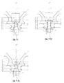
도 3은 본 발명의 특정 실시예에 따른 노즐의 전방 단부의 단면 상세도(각도(β) = 60°)를 도시하며;
도 4는 본 발명의 특정 실시예에 따른 노즐의 전방 단부의 단면 상세도(오목 형태로 좁아지는 부분(A1), α1 = 32°)를 도시하며;
도 5는 본 발명의 특정 실시예에 따른 노즐의 전방 단부의 단면 상세도(볼록 형태로 좁아지는 부분(A1), α1 = 32°)를 도시하며;
도 5.1은 본 발명의 특정 실시예에 따른 노즐의 전방 단부의 단면 상세도(볼록 형태로 좁아지는 부분(A1), α1 = 32°)를 도시하며;
도 6은 본 발명의 특정 실시예에 따른 노즐의 전방 단부의 단면 상세도(단계적 형태로 좁아지는 부분(A1), α1 = 32°)를 도시하며;
도 7은 본 발명의 특정 실시예에 따른 노즐의 전방 단부의 단면 상세도(원뿔 형태로 넓어지는 부분(A3), γ = 5°)를 도시하며;
도 7.1은 본 발명의 특정 실시예에 따른 노즐의 전방 단부의 단면 상세도(오목 형태로 넓어지는 부분(A3), γ1 = 5°)를 도시하며;
도 7.2는 본 발명의 특정 실시예에 따른 노즐의 전방 단부의 단면 상세도(볼록 형태로 넓어지는 부분(A3), γ1 = 5°)를 도시하며;
도 8은 본 발명의 특정 실시예에 따른 노즐의 전방 단부의 단면 상세도(원뿔 형태로 좁아지는 부분(A3), γ = 175°)를 도시하며.
도 8.1은 본 발명의 특정 실시예에 따른 노즐의 전방 단부의 단면 상세도(볼록 형태로 좁아지는 부분(A3), γ1 = 175°)를 도시하며;
도 8.2는 본 발명의 특정 실시예에 따른 노즐의 전방 단부의 단면 상세도(오목 형태로 좁아지는 부분(A3), γ1 = 175°)를 도시하며.
도 9는 본 발명의 특정 실시예에 따른 노즐의 전방 단부의 단면 상세도(원뿔 형태로 넓어지는 부분(A5), δ = 80°)를 도시하며;
도 9.1은 본 발명의 특정 실시예에 따른 노즐의 전방 단부의 단면 상세도(오목 형태로 넓어지는 부분(A5), δ1 = 45°)를 도시하며;
도 9.2는 본 발명의 특정 실시예에 따른 노즐의 전방 단부의 단면 상세도(볼록 형태로 넓어지는 부분(A5), δ1 = 45°)를 도시하며;
도 9.3은 본 발명의 특정 실시예에 따른 노즐의 전방 단부의 단면 상세도(오목 형태로 넓어지는 부분(A5), δ1 = 45°)를 도시하며;
도 10은 본 발명의 특정 실시예에 따른 노즐의 전방 단부의 단면 상세도(원뿔 형태로 넓어지는 부분(A7), ε = 5°)를 도시하며;
도 11은 본 발명의 특정 실시예에 따른 노즐의 전방 단부의 단면 상세도(원뿔 형태로 좁아지는 부분(A7), ε = 175°)를 도시하며;
도 12는 영역(A10 및 A20)을 예시하기 위한 목적을 위해 본 발명의 특정 실시예에 따른 노즐의 전방 단부의 단면 상세도 및 확대 단면 상세도(저면)를 예로서 도시하며;
도 13 및 도 13a는 영역(A30 및 A31)을 예시하기 위한 목적을 위해 본 발명의 특정 실시예에 따른 노즐의 전방 단부의 2개의 확대 단면 상세도를 예로서 도시하며;
도 14는 체적(V10)을 예시하기 위한 목적을 위해 본 발명의 특정 실시예에 따른 노즐의 전방 단부의 확대된 단면 상세도를 예로서 도시하며;
도 15는 체적(V30)을 예시하기 위한 목적을 위해 전방 단부(22)의 확대 단면 상세도를 예로서 도시하며;
도 16은 본 발명의 특정 실시예에 따른 플라즈마 토치 헤드의 단면도이며;
도 17은 본 발명의 특정 실시예에 따른 노즐, 노즐 캡, 노즐 보호 캡, 및 가스 전도 유닛으로 구성된 장치의 단면도이며;
도 17a는 돌출된 원형 영역(A70)을 예시하기 위한 목적을 위해 노즐 및 노즐 보호 캡으로 구성된 장치의 확대 상세도를 도시하며;
도 18은 본 발명의 특정 실시예에 따른 노즐, 노즐 보호 캡, 및 가스 전도 유닛으로 구성된 장치의 단면도이며;
도 18a는 돌출된 원형 영역(A80)을 예시하기 위한 목적을 위해 노즐 및 노즐 보호 캡으로 구성된 장치의 확대 상세도를 도시하며;
도 20은 2차 가스를 위한 가스 전도 유닛을 예로서 도시하며;
도 19는 본 발명의 특정 실시예에 따른 노즐, 전극, 및 가스 전도 유닛으로 구성된 장치의 단면도이며;
도 21은 플라즈마 가스를 위한 가스 전도 유닛을 예로서 도시한다.Other features and advantages of the invention will appear from the following description of the appended claims and exemplary embodiments based on the schematic drawings:
1 shows a cross-sectional and cross-sectional detail view (plan view) of the front end of a nozzle according to a particular embodiment of the invention;
2 shows a cross-sectional detail view (angle (β) = 120 °) of the front end of the nozzle according to a particular embodiment of the invention;
3 shows a cross-sectional detail view (angle (β) = 60 °) of the front end of the nozzle according to a particular embodiment of the invention;
Figure 4 shows a cross-sectional detail view of the front end of the nozzle according to a particular embodiment of the invention (part A1 narrowed in the form of concave, α1 = 32 °);
5 shows a cross-sectional detail view of the front end of the nozzle according to a particular embodiment of the present invention (the convex narrowing portion A1, α1 = 32 °);
Figure 5.1 shows a cross-sectional detail view of the front end of the nozzle according to a particular embodiment of the present invention (the convex narrowing portion A1, α1 = 32 °);
FIG. 6 shows a cross-sectional detail view of the front end of the nozzle according to a particular embodiment of the invention (part A1 narrowed in a stepwise fashion, α1 = 32 °);
7 shows a cross-sectional detail view of the front end of the nozzle according to a particular embodiment of the present invention (the portion A3 extending in the form of a cone, γ = 5 °);
FIG. 7.1 shows a cross-sectional detail view of the front end of the nozzle according to a particular embodiment of the present invention (part A3 extending in the form of concave, γ1 = 5 °);
7.2 shows a cross-sectional detail view of the front end of the nozzle according to a particular embodiment of the present invention (the convex widening portion A3, γ1 = 5 °);
Figure 8 shows a cross-sectional detail view of the front end of the nozzle according to a particular embodiment of the present invention (a narrowed portion (A3) in the form of a cone, γ = 175 °).
FIG. 8.1 shows a cross-sectional detail view of the front end of the nozzle according to a particular embodiment of the invention (the convex narrowing portion A3, γ1 = 175 °);
Figure 8.2 shows a cross-sectional detail view of the front end of the nozzle according to a particular embodiment of the present invention (a narrowed portion (A3) in the form of concave, γ1 = 175 °).
9 shows a cross-sectional detail view of the front end of the nozzle according to a particular embodiment of the present invention (the portion A5 extending in the form of a cone, δ = 80 °);
9.1 shows a cross-sectional detail view of the front end of the nozzle according to a particular embodiment of the present invention (the concave widening portion A5, δ1 = 45 °);
9.2 shows a cross-sectional detail view of the front end of the nozzle according to a particular embodiment of the invention (the convex widening portion A5, δ1 = 45 °);
9.3 shows a cross-sectional detail view of the front end of the nozzle according to a particular embodiment of the present invention (portion widening in concave shape (A5), δ1 = 45 °);
10 shows a cross-sectional detail view of the front end of the nozzle according to a particular embodiment of the present invention (part A7 extending in the form of a cone, ε = 5 °);
11 shows a cross-sectional detail view of the front end of the nozzle according to a particular embodiment of the present invention (conical narrowing portion A7, ε = 175 °);
12 shows, by way of example, a cross-sectional detail view and an enlarged cross-sectional detail view (bottom) of the front end of the nozzle according to a particular embodiment of the present invention for the purpose of illustrating the regions A10 and A20;
13 and 13A show by way of example two enlarged cross-section details of the front end of the nozzle according to a particular embodiment of the invention for the purpose of illustrating the regions A30 and A31;
14 shows as an example an enlarged cross-sectional detail view of the front end of a nozzle according to a particular embodiment of the invention for the purpose of illustrating the volume V10;
15 shows an enlarged cross-sectional detail view of the
16 is a cross-sectional view of a plasma torch head according to a particular embodiment of the present invention;
17 is a cross-sectional view of a device composed of a nozzle, a nozzle cap, a nozzle protection cap, and a gas conduction unit according to a particular embodiment of the present invention;
FIG. 17A shows an enlarged detail view of a device composed of a nozzle and a nozzle protection cap for the purpose of illustrating the protruding circular area A70;
18 is a cross-sectional view of a device consisting of a nozzle, a nozzle protection cap, and a gas conduction unit according to a particular embodiment of the present invention;
FIG. 18A shows an enlarged detail view of a device composed of a nozzle and a nozzle protection cap for the purpose of illustrating the protruding circular area A80;
20 shows as an example a gas conduction unit for secondary gas;
19 is a cross-sectional view of a device composed of a nozzle, an electrode, and a gas conduction unit according to a particular embodiment of the present invention;
21 shows a gas conduction unit for plasma gas as an example.
플라즈마 아크 토치의 단면도(평면) 및 단면 상세도(저면)로 도 1에 도시된 노즐(2)은, 세로 방향 축(M)을 따라서 연장되는 전체 길이(L20), 내부 표면(21) 및 외부 표면(23), 전방 단부(22) 및 후방 단부(28), 및 전방 단부(22)에 있는 노즐 개구(24)를 가지는 바디(20)를 포함한다. 또한, 바디(20)는 그 전방 단부(22)에 그루브(238)를 가진다. 노즐(2)이 플라즈마 아크 토치에 설치될 때, 원형 링(240)(도 16 참조)은 노즐(2)과 노즐 캡(5) 사이의 공간을 밀봉하는 목적을 위해 그루브(238)에 위치된다(도 16 참조).The
노즐(2)의 바디(20)의 내부 표면(21)은, 전방 단부(22)(노즐 개구(24))로부터 진행하여, 먼저 세로 방향 축(M)을 따라서 연장되고, 예를 들어 1.0 ㎜의 길이(L1)에 걸쳐서 그 내부 표면(211)과 세로 방향 축(M) 사이의 각도(α), 이 경우에 예를 들어 대략 19°로 원뿔 형태로 좁아지고 그런 다음 그 내부 표면(213)과 세로 방향 축(M) 사이에 각도(β), 이 경우에 예를 들어 90°를 형성하는 세로 방향 축(M)의 방향으로 돌출부를 가지는 제1 부분(A1)을 가진다. 노즐 개구(24)는 전방 단부(22)에서 직접, 이 경우에 예를 들어 1.9 ㎜의 직경(D1), 및 제1 부분(A1)의 내부 표면(211)의 원뿔형 영역의 단부에서, 직경(D2), 이 경우에 예를 들어 1.2 ㎜를 가진다. 돌출부로 인하여, 이 경우에 예를 들어 0.1 ㎜의 노즐 개구(24)의 직경은 이 경우에 예를 들어 1.0 ㎜의 D3로 감소한다.The inner surface 21 of the
이것은 직경(D3) 및 길이(L3), 예를 들어 1.0 ㎜를 가지는 제2 부분(A3)에 의해 직접 인접되며, 제2 부분은 원통형 내부 표면(220)을 가진다. 상기 부분은 제3 부분(A5)에 의해 인접되고, 그 내부 표면(224)은 직경(D3)으로부터 직경(D7)으로, 이 경우에 예를 들어 2.8 ㎜로 그 내부 표면(224)과 세로 방향 축(M) 사이의 각도(δ), 이 경우에 예를 들어 45°를 가진 원뿔형으로 넓어진다. 상기 부분은 길이(L5), 이 경우 예를 들어 0.9 ㎜에 걸쳐서 세로 방향 축(M)을 따라서 연장된다. 상기 부분은 직경(D7)을 가지는 제4 부분(A7)에 의해 인접되며, 이는 길이(L7), 예를 들어 1.2 ㎜를 가지는 원통형 내부 표면(227)을 가진다. 이것은 원뿔 형태로 넓어지는 추가의 지역에 의해 인접된다.It is directly adjacent by a second part A3 having a diameter D3 and a length L3, for example 1.0 mm, the second part having a cylindrical
D1 = 1.9 ㎜이고 D3 = 1.0 ㎜인 경우에, D1은 직경(D3)의 1.9배에 해당한다. 직경(D1)은 직경(D3)보다 0.9 ㎜ 더 크다. In the case where D1 = 1.9 mm and D3 = 1.0 mm, D1 corresponds to 1.9 times the diameter D3. The diameter D1 is 0.9 mm larger than the diameter D3.
노즐 개구(24)의 전방 단부(22)에서 직접 제1 부분(A1)의 직경(D1)에 의해 세로 방향 축(M)에 직각으로 형성된 영역(A10)(이 영역은 도 12에 도시되어 있다)은 [A10 = 3.141/4 * D12]에 따라서 결정된, 대략 2.8 ㎟에 이른다.An area A10 formed at a right angle to the longitudinal axis M by the diameter D1 of the first portion A1 directly at the
노즐 개구(24)의 제2 부분(A3)의 최소 직경(D3)에 의해 세로 방향 축(M)에 직각으로 형성된 영역(A30)(이 영역은 도 13에 도시되어 있다)은 [A30 = 3.141/4 * D32]에 따라서 결정된, 대략 0.8 ㎟에 이른다.The area A30 formed at a right angle to the longitudinal axis M by the minimum diameter D3 of the second portion A3 of the nozzle opening 24 (this area is shown in FIG. 13) is [A30 = 3.141 / 4 * D3 2 ].
그러므로, 영역(A10)은 영역(A30)의 대략 3.6배에 해당한다.Therefore, the area A10 corresponds to approximately 3.6 times the area A30.
제1 부분(A1)의 길이 L1 = 1.0 ㎜ 및 제2 부분(A3)의 길이(L3) = 1.0 ㎜는 L1/L3 = 1의 비를 초래한다. 제2 부분(A3)의 길이(L3) 및 직경(D3)의 몫은 마찬가지로 1에 이른다. 또한, 직경(D1) = 1.9 ㎜는 직경(D7) = 2.8 ㎜보다 작다.The length L1 of the first portion A1 = 1.0 mm and the length L3 of the second portion A3 = 1.0 mm results in a ratio of L1 / L3 = 1. The quotient of the length L3 and the diameter D3 of the second portion A3 likewise reaches one. Also, the diameter D1 = 1.9 mm is smaller than the diameter D7 = 2.8 mm.
도 1은 또한 전방 단부(22)에서 직경(D1)을 가지는 노즐 개구(24)의 바디 가장자리(201)와 직경(D3)을 가진 노즐 개구(24)의 제1 부분(A1)으로부터 제2 부분(A3)으로의 천이부에서의 바디 가장자리(203) 사이에서 연장되는 가상 연결 라인(V1)을 또한 도시한다. 연결 라인(V1) 및 세로 방향 축(M)에 의해 둘러싸인 각도(α1)는 대략 24°에 이른다.1 also shows a second part from the first edge A1 of the
제1 부분(A1)의 노즐 개구(24)의 내부 표면(211 및 213)에 의해 형성된 체적(V10)은 [V10 = 3.141 * L1/3 *((D1/22)2 +(D1/2 * D2/2) + (D2/22)2]에 따라서 계산된, 대략 1.9 ㎣에 이른다.The volume V10 formed by the
제2 부분(A3)의 노즐 개구(24)의 내부 표면(220)에 의해 형성된 체적(V30)은 [V30 = 3.141 *(D3/22)2 * L3]에 따라서 계산된, 대략 0.8 ㎣에 이른다. 그러므로, 체적(V10)은 체적(V30)보다 약 1.9배 더 크다.The volume V30 formed by the
도 2는 도 1과 유사한 노즐(2)의 추가의 예시적인 실시예의 상세도를 도시한다. 상기 노즐은 세로 방향 축(M)의 방향으로의 돌출부가 그 내부 표면(213) 및 세로 방향 축(M) 사이에 각도(β) = 100°를 형성한다는 점에서 도 1의 노즐과 다르다.FIG. 2 shows a detailed view of a further exemplary embodiment of a
도 3은 도 1과 유사한 노즐(2)의 추가의 예시적인 실시예의 상세도를 도시한다. 상기 노즐은 세로 방향 축(M)의 방향으로의 돌출부가 그 내부 표면(213)과 세로 방향 축(M) 사이에 각도(β) = 60°를 형성한다는 점에서 도 1의 노즐과 다르다.3 shows a detailed view of a further exemplary embodiment of a
도 4는 도 1과 유사한 노즐(2)의 추가의 예시적인 실시예의 상세도를 도시한다. 상기 노즐은 제1 부분(A1)이 전방 단부로부터 진행하여, 오목 형태로 좁아지는 내부 표면(211)을 가진다는 점에서 도 1의 노즐과 다르다. 전방 단부(22)에서 직경(D1)을 가지는 노즐 개구(24)의 바디 가장자리(201)와 직경(D3)을 가지는 노즐 개구(24)의 제1 부분(A1)으로부터 제2 부분(A3)으로의 천이부에서의 바디 가장자리(203) 사이에서 연장되는 가상 연결 라인(V1)은 예를 들어 세로 방향 축(M)과 함께 대략 32°의 각도(α1)를 둘러싼다. 이 경우에 직경(D1)은 예를 들어 2.4 ㎜, 직경(D3) = 1.4 ㎜이고, 그러므로 직경(D1)은 직경(D3)의 대략 1.7배에 해당한다.4 shows a detailed view of a further exemplary embodiment of a
노즐 개구(24)의 전방 단부(22)에서 직접 제1 부분(A1)의 직경(D1)에 의해 세로 방향 축(M)에 직각으로 형성된 영역(A10)(이 영역은 도 12에 도시되어 있다)은 [A10 = 3.141/4 * D12]에 따라서 결정된, 대략 4.5 ㎟에 이른다.An area A10 formed at a right angle to the longitudinal axis M by the diameter D1 of the first portion A1 directly at the
노즐 개구(24)의 제2 부분(A3)의 최소 직경(D3)에 의해 세로 방향 축(M)에 직각으로 형성된 영역(A30)(이 영역은 도 13에 도시되어 있다)은 [A30 = 3.141/4 * D32]에 따라서 결정된, 대략 1.5 ㎟에 이른다.The area A30 formed at a right angle to the longitudinal axis M by the minimum diameter D3 of the second portion A3 of the nozzle opening 24 (this area is shown in FIG. 13) is [A30 = 3.141 / 4 * D3 2 ].
그러므로, 영역(A10)은 영역(A30)의 대략 2.9배에 해당한다.Therefore, the area A10 corresponds to approximately 2.9 times the area A30.
길이(L1)는 예를 들어 0.8 ㎜에 이르고, 길이(L3)는 예를 들어 1.2 ㎜에 이르고, 그러므로, 길이(L1)는 길이(L3)의 0.67배에 해당한다.The length L1 reaches, for example, 0.8 mm, and the length L3 reaches, for example, 1.2 mm, and therefore the length L1 corresponds to 0.67 times the length L3.
제2 부분(A3)의 길이(L3) = 1.2 ㎜ 및 직경(D3) = 1.4 ㎜의 몫은 0.86에 이른다. 또한, 직경(D1) = 2.4 ㎜는 직경(D7) = 3.0 ㎜보다 작다.The share of the length (L3) = 1.2 mm and the diameter (D3) = 1.4 mm of the second portion (A3) reaches 0.86. In addition, diameter (D1) = 2.4 mm is smaller than diameter (D7) = 3.0 mm.
제1 부분(A1)의 노즐 개구(24)의 내부 표면(211)에 의해 형성된 체적(V10)은 대략 2.3 ㎣에 이른다. 제2 부분(A3)의 노즐 개구(24)의 내부 표면(220)에 의해 형성된 체적(V30)은 대략 1.8 ㎣에 이른다. 따라서 체적(V10)은 체적(V30)보다 약 1.3배 더 크다.The volume V10 formed by the
도 5는 도 4와 유사한 노즐(2)의 추가의 예시적인 실시예의 상세도를 도시한다. 상기 노즐은 제1 부분(A1)이 전방 단부으로부터 진행하여, 볼록 형태로 좁아지는 내부 표면(211)을 가진다는 점에서 도 1의 노즐과 다르다. 전방 단부(22)에서 직경(D1)을 가지는 노즐 개구(24)의 바디 가장자리(201)와 제1 부분(A1)으로부터 직경(D3)을 가지는 노즐 개구(24)의 제2 부분(A3)으로의 천이부에서의 바디 가장자리(203) 사이에서 연장되는 가상 연결 라인(V1)은 예를 들어 세로 방향 축(M)과 함께 대략 32°의 각도(α1)를 둘러싼다. 이 경우에 직경(D1)은 예를 들어 2.4 ㎜에 이르고, 직경(D3)은 1.4 ㎜에 이르고, 그러므로 직경(D1)은 직경(D3)의 대략 1.7배에 해당한다. 길이(L1)는 예를 들어 0.8 ㎜에 이르고, 길이(L3)는 예를 들어 1.2 ㎜에 이르며, 그러므로, 길이(L1)는 길이(L3)의 대략 0.67배에 해당한다.5 shows a detailed view of a further exemplary embodiment of a
제2 부분(A3)의 길이(L3) = 1.2 ㎜ 및 직경(D3) = 1.4 ㎜의 몫은 대략 0.86에 이른다. 또한, 직경(D1) = 2.4 ㎜는 직경(D7) = 3.0 ㎜보다 작다.The share of the length L3 of the second portion A3 = 1.2 mm and the diameter D3 = 1.4 mm amounts to approximately 0.86. In addition, diameter (D1) = 2.4 mm is smaller than diameter (D7) = 3.0 mm.
도 4로부터의 예시적인 사양은 영역(A10 및 A30)에 적용되며, 체적(V10 및 V30)의 사양에도 동일하게 적용된다.The exemplary specifications from FIG. 4 apply to the regions A10 and A30, and the same applies to the specifications of the volumes V10 and V30.
예를 들어 볼록 내부 표면(211)이 연속적 또는 "흐르는" 형태로 표면(230)에 합쳐지기 때문에, 바디 가장자리(201)가 명확하게 인식될 수 없으면, 바디 가장자리를 가지는 표면(들)의 영역은 노즐(2)의 후방 단부(28)로부터 보았을 때, 내부 표면(211)에 적용된 접선(T)과 세로 방향 축(M) 사이에서 65°의 각도(α2)가 초과되었다는 것을 의미한다. 가상 연결 라인(V1)은 상기 영역과 바디 가장자리(203) 사이에서 연장된다. 이러한 것은 도 5.1에 도시되어 있다. If the
도 6은 도 4와 유사한 노즐(2)의 추가의 예시적인 실시예를 도시한다. 상기 노즐은 제1 부분(A1)이 전방 단부으로부터 진행하여, 단계적 형태로 좁아지는 내부 표면(211)을 가진다는 점에서 도 4의 노즐과 다르다. 전방 단부(22)에서 직경(D1)을 가지는 노즐 개구(24)의 바디 가장자리(201)와 제1 부분(A1)으로부터 직경(D3)을 가지는 노즐 개구(24)의 제2 부분(A3)으로의 천이부에서의 바디 가장자리(203) 사이에서 연장되는 가상 연결 라인(V1)은 예를 들어 세로 방향 축(M)과 함께 대략 32°의 각도(α1)를 둘러싼다. 이 경우에 직경(D1)은 예를 들어 2.4㎜에 이르고, 직경(D3) = 1.4 ㎜에 이르고, 그러므로, 직경(D1)은 직경(D3)의 1.7 배에 해당한다. 제1 부분(A1)의 길이(L1) = 0.8 ㎜ 및 제2 부분(A3)의 길이(L3) = 1.2 ㎜는 L1/L3 = 0.67의 비를 초래한다. 제2 부분(A3)의 길이(L3) 및 직경(D3)의 몫은 대략 0.86에 이른다. 직경(D7)은 예를 들어 3.0 ㎜에 이른다. 그러므로, 직경(D1) = 2.4 ㎜는 직경(D7) = 3.0 ㎜보다 작다.FIG. 6 shows a further exemplary embodiment of a
도 4로부터의 예시적인 사양은 영역(A10 및 A30)에 적용되며, 체적(V10 및 V30)의 사양에도 동일하게 적용된다.The exemplary specifications from FIG. 4 apply to the regions A10 and A30, and the same applies to the specifications of the volumes V10 and V30.
도 7은 도 1과 유사한 노즐(2)의 추가의 예시적인 실시예의 상세도를 도시한다. 치수는 도 1의 치수와 동일하다. 단지 제2 부분(A3)만이 노즐(2)의 전방 단부(22)로부터 보았을 때 그 내부 표면(220)이 세로 방향 축(M)에 대해 예를 들어 5°의 각도(γ)로 넓어지도록 설계된다. 여기에서, 넓어지는 것은 원뿔 형태로 실현된다. 따라서, 부분(A5)으로의 천이부에서 부분(A3)의 직경(D31)은 노즐 개구(24)의 제1 부분(A1)으로부터 제2 부분(A3)으로의 천이부에서의 직경(D3)보다 더 크다.7 shows a detailed view of a further exemplary embodiment of a
도 7.1은 도 7과 유사한 노즐(2)의 추가의 예시적인 실시예의 상세도를 도시한다. 치수는 도 7로부터의 치수와 동일하다. 단지 제2 부분(A3)만이 노즐(2)의 전방 단부(22)로부터 보았을 때, 그 내부 표면(220)이 오목 형태로 넓어지도록 설계된다. 제1 부분(A1)으로부터 제2 부분(A3)으로의 천이부에서의 바디 가장자리(203)와 제2 부분(A3)으로부터 제3 부분(A5)으로의 천이부에서의 바디 가장자리(205) 사이에서 연장되는 가상 연결 라인(V3)은 예를 들어 세로 방향 축(M)과 함께 대략 5°의 각도(γ1)를 둘러싼다. 그러므로, 이 예에서, 부분(A5)으로의 천이부에서 부분(A3)의 직경(D31)은 노즐 개구(24)의 제1 부분(A1)으로부터 제2 부분(A3)으로의 천이부에서의 직경(D3)보다 크다.FIG. 7.1 shows a detailed view of a further exemplary embodiment of a
도 7.2는 도 7.1과 유사한 노즐(2)의 추가의 예시적인 실시예의 상세도를 도시한다. 치수는 도 7.1로부터의 치수와 동일하다. 단지 제2 부분(A3)만이 노즐(2)의 전방 단부(22)로부터 보았을 때, 그 내부 표면(220)이 오목하지 않고 오히려 볼록 형태로 넓어지도록 설계된다.FIG. 7.2 shows a detailed view of a further exemplary embodiment of a
도 8은 도 1과 유사한 노즐(2)의 추가의 예시적인 실시예의 상세도를 도시한다. 제2 부분(A3)은 노즐(2)의 전방 단부(22)로부터 보았을 때, 그 내부 표면(220)이 예를 들어 세로 방향 축(M)에 대해 175°의 각도(γ)로 좁아지도록 설계된다. 여기에서, 좁아지는 것은 원뿔 형태로 실현된다. 그러므로, 제1 부분(A1)으로부터 제2 부분(A3)으로의 천이부에서의 제2 부분(A3)의 직경(D32) = 1.17 ㎜은 노즐 개구(24)의 제2 부분(A3)으로부터 제3 부분(A)으로의 천이부에서의 직경(D3) = 1 ㎜보다 크다. 직경(D2)은 1.4 ㎜에 이르고, 직경(D1) = 2.1 ㎜에 이른다. 각도(α)는 19°에 이르고, 각도(α1)는 21°에 이른다.8 shows a detailed view of a further exemplary embodiment of a
도 8.1은 도 8과 유사한 노즐(2)의 추가의 예시적인 실시예의 상세도를 도시한다. 그러나, 제2 부분(A3)은 노즐(2)의 전방 단부(22)로부터 보았을 때, 그 내부 표면(220)이 볼록 형태로 좁아지도록 설계된다. 제1 부분(A1)으로부터 제2 부분(A3)으로의 천이부에서의 바디 가장자리(203)와 제2 부분(A3)으로부터 제3 부분(A5)으로의 천이부에서의 바디 가장자리(205) 사이에서 연장되는 가상 연결 라인(V3)은 예를 들어 세로 방향 축(M)과 함께 대략 175°의 각도(γ1)를 둘러싼다. 그러므로, 제1 부분(A1)으로부터 제2 부분(A3)으로의 천이부에서 제2 부분(A3)의 직경(D32) = 1.17 ㎜은 노즐 개구(24)의 제2 부분(A3)으로부터 제3 부분(A)으로의 천이부에서의 직경(D3) = 1 ㎜보다 크다. 직경(D2)은 1.4 ㎜에 이르고, 직경(D1)은 2.1 ㎜에 이른다. 이 예에서 각도(α)는 19°에 이르고, 이 예에서 각도(α1)는 21°에 이른다.FIG. 8.1 shows a detailed view of a further exemplary embodiment of a
도 8.2는 도 8.1과 유사한 노즐(2)의 추가의 예시적인 실시예의 상세도를 도시한다. 그러나, 제2 부분(A3)은 노즐(2)의 전방 단부(22)로부터 보았을 때, 그 내부 표면(220)이 볼록하지 않고 오히려 오목 형태로 좁아지도록 설계된다.FIG. 8.2 shows a detailed view of a further exemplary embodiment of a
도 9는 도 1과 유사한 노즐(2)의 추가의 예시적인 실시예의 상세도를 도시한다. 치수는 도 1로부터의 치수와 동일하다. 제3 부분(A5)은 예를 들어 그 내부 표면(224)과 세로 방향 축(M) 사이에서 80°의 각도(δ)를 가지며 넓어진다. 그러나, 이는 그 외부 윤곽이 추가의 예시적인 실시예와 다른 노즐이다. 상기 노즐은 예를 들어 노즐에 대한 액체 냉각이 없는 플라즈마 토치, 레이저 헤드 또는 플라즈마 레이저 헤드에 사용하는데 적합하다. 이 예에서, 상기 노즐은 둥근 링을 수용하기 위한 그루브(238)를 가지지 않는다. 대응하는 장치가 도 18에 도시되어 있다.9 shows a detailed view of a further exemplary embodiment of a
도 9.1은 도 9와 유사한 노즐(2)의 추가의 예시적인 실시예의 상세도를 도시한다. 치수는 도 9로부터의 치수와 동일하다. 단지 제3 부분(A5)만이 노즐(2)의 전방 단부(22)로부터 보았을 때, 그 내부 표면(224)이 오목 형태로 넓어지도록 설계된다. 제2 부분(A3)으로부터 제3 부분(A5)으로의 천이부에서의 바디 가장자리(205)(이 경우에, "내부 모서리" 또는 "바디 내부 가장자리"로 지칭될 수 있음)와 제3 부분(A5)으로부터 제4 부분(A7)으로의 천이부에서의 바디 가장자리(206)(이 경우에 "내부 모서리" 또는 "바디 내부 가장자리"로 지칭될 수 있음) 사이에서 연장되는 가상 연결 라인(V4)은 예를 들어 세로 방향 축(M)과 함께 대략 45°의 각도(γ1)를 둘러싼다.FIG. 9.1 shows a detailed view of a further exemplary embodiment of a
예를 들어 오목한 내부 표면이 연속 또는 "흐르는" 형태로 내부 표면(227)에 합쳐지기 때문에 바디 가장자리(206)가 명확하게 인식될 수 없으면, 내부 표면(들)의 영역(206)은, 노즐의 전방 단부(22)로부터 보았을 때, 20°의 각도(δ2)가 내부 표면(224)에 적용된 접선(T)과 세로 방향 축(M) 사이에서 못미친다. 이것은 도 9.3에 도시되어 있다.If the
도 9.2는 도 9와 유사한 노즐(2)의 추가의 예시적인 실시예의 상세도를 도시한다. 치수는 도 9로부터의 치수와 동일하다. 단지 제3 부분(A5)만이 노즐(2)의 전방 단부(22)로부터 보았을 때, 그 내부 표면(224)이 볼록 형태로 넓어지도록 설계된다. 제2 부분(A3)으로부터 제3 부분(A5)으로의 천이부에서의 바디 가장자리(205)와 제3 부분(A5)으로부터 제4 부분(A7)으로의 천이부에서의 바디 가장자리(206) 사이에서 연장되는 가상 연결 라인(V4)은 예를 들어 세로 방향 축(M)과 함께 대략 약 45°의 각도(γ1)를 둘러싼다.9.2 shows a detailed view of a further exemplary embodiment of a
예를 들어 오목한 내부 표면(224)이 연속 또는 "흐르는" 형태로 표면(227)에 합쳐지기 때문에, 바디 가장자리(206)가 명확하게 인식될 수 없으면, 바디 가장자리(206)를 가지는 내부 표면(들)의 영역은 노즐(2)의 전방 단부(22)로부터 보았을 때, 20°의 각도(δ2)가 내부 표면(224)에 적용된 접선(T)과 세로 방향 축(M) 사이에서 못미친다는 것을 의미한다. 가상 연결 라인(V4)은 그런 다음 상기 영역(206)과 바디 가장자리(205) 사이에서 연장된다. 이것은 오목하게 넓어진 제3 부분(A5)을 도시하는 도 9.3에 도시되어 있다.If the
도 10은 도 1과 유사한 노즐(2)의 추가의 예시적인 실시예의 상세도를 도시한다. 치수는 도 1로부터의 치수와 동일하다. 제4 부분(A7)은 예를 들어 그 내부 표면(227)과 세로 방향 축(M) 사이에서 5°의 각도(ε)를 가지며 넓어진다.10 shows a detailed view of a further exemplary embodiment of a
도 11은 도 1과 유사한 노즐(2)의 추가의 예시적인 실시예의 상세도를 도시한다. 치수는 도 1로부터의 치수와 동일하다. 제4 부분(A7)은 예를 들어 내부 표면(227)과 세로 방향 축(M) 사이에서 175°의 각도(ε)를 가지며 좁아진다.FIG. 11 shows a detailed view of a further exemplary embodiment of a
예를 들어 0.1 ㎜의 크기의 반경은 각각의 부분(A1, A3, A4, A5 및 A7) 사이의 천이부에 배열될 수 있다.For example, a radius of the size of 0.1 mm can be arranged in the transition between each part A1, A3, A4, A5 and A7.
도 12, 도 13 및 도 13a는 노즐 개구(24)의 직경(D1, D2 및 D3)에 의해 세로 방향 축(M)에 직각으로 형성된 영역(A10, A20, A30 및 A31)을 도시한다. 도 1 내지 도 11에서의 예시적인 실시예에서, 영역(A10)은 영역(A30)보다 적어도 1.7배, 유리하게 적어도 2.1배 더 크다. 또한, 이것은 영역(A30)보다 최대 4배, 유리하게 최대 3.7배 더 크다.12, 13 and 13A show the regions A10, A20, A30 and A31 formed perpendicular to the longitudinal axis M by the diameters D1, D2 and D3 of the
도 14는 제1 부분(A1)의 노즐 개구(24)의 내부 표면(211 및 213)에 의해 둘러싸인 체적(V10)을 도시하고, 도 15는 내부 표면(220)에 의해 둘러싸인 제2 부분(A3)의 노즐 개구(24)의 체적(V30)을 도시한다. 예시적인 실시예에서, 체적(V10)은 체적(V30)보다 유리하게 적어도 1.3배 더 크고, 및/또는 최대 2.5배, 유리하게 최대 2.2배 더 크다.FIG. 14 shows the volume V10 surrounded by the
도 16은 플라즈마 토치의 구성 부분일 수 있는 플라즈마 토치 헤드(1)의 단면도를 도시한다.16 shows a cross-sectional view of a
플라즈마 토치 헤드(1)는 본 발명에 따른 토치 바디(8), 전극(3), 노즐(2), 노즐 캡(5), 노즐(2)을 수용하는 노즐 브래킷(81), 및 노즐(2)을 노즐 브래킷(81)에 고정하는 노즐 보호 캡(6)을 가진다.The
이 도면에서, 도 1로부터의 노즐(2)이 예로서 사용된다.In this figure, the
전극(3)의 전방 단부(33)는 노즐(2)의 내부 공간 내로 돌출된다. 또한, 플라즈마 가스 또는 공정 가스(PG)를 위한 가스 전도 유닛(4)은 전극(3)과 노즐(2) 사이에 위치된다. 가스 전도 유닛(4)은, 플라즈마 가스 또는 공정 가스를 통과시켜 전도하고, 이 경우에 예를 들어 전극(3)과 노즐(2) 사이의 내부 공간으로 반경 방향으로 이어지는 개구(41)들을 가진다. 플라즈마 가스 또는 공정 가스(PG)는 반경에 대한 오프셋에 의해 회전하도록 설정될 수 있다. 가스 전도 유닛(4)은 전극(3)과 노즐(2)을 서로 전기적으로 절연시킨다. 전극(3)은 내부에서 액체 냉각될 수 있으며; 이러한 것은 본 명세서에서 설명되지 않는다. 냉각 매체(WV-공급 라인, WR-복귀 라인)는 노즐(2)과 노즐 캡(5) 사이의 공간(51)으로 유동하여, 이러한 것들을 냉각시킨다.The
노즐(22)의 전방 단부는 노즐 보호 캡(6)에 의해 적어도 부분적으로 덮여있다. 노즐 보호 캡(6)은 세로 방향 축(M) 상의 노즐 개구(24)와 정렬되는 개구(64)를 가진다. 2차 가스(SG)를 위한 가스 전도 유닛(7)은 노즐 캡(5), 노즐(2)의 전방 단부(22)와 노즐 보호 캡(6) 사이에 위치된다. 가스 전도 유닛(7)은, 2차 가스(SG)를 통과시켜서 전도하고, 이 경우에 예를 들어 노즐 캡(5), 노즐(2)의 전방 단부(22)와 노즐 보호 캡(6) 사이의 내부 공간(61) 내로 반경 방향으로 이어지는 개구(71)들을 가진다. 플라즈마 가스 또는 공정 가스(PG)는 반경 방향에 대한 오프셋에 의해 회전하도록 설정될 수 있다. 가스 전도 유닛(7)은 노즐 캡(5)과 노즐 보호 캡(6)을 서로 전기적으로 절연시킨다.The front end of the
플라즈마 절단 동안, 플라즈마 가스 또는 공정 가스(PG)는 아크에 의해 이온화되고, 궁극적으로 노즐 개구(24) 및 노즐 보호 캡(64)의 개구 밖으로 유동한다.During plasma cutting, the plasma gas or process gas (PG) is ionized by the arc and ultimately flows out of the opening of the
도 17 및 도 17a는 도 16으로부터의 플라즈마 토치 헤드의 구성 부분인 본 발명의 특정 실시예에 따른 구성의 단면 상세도를 각각 도시한다. 그러나, 이러한 장치는 마찬가지로 레이저 절단 헤드의 구성 부분 또는 플라즈마 레이저 절단 헤드일 수 있다. 청구된 장치는 노즐(2) 및 노즐 보호 캡(6)을 포함한다. 노즐 캡(5) 및 가스 전도 유닛(7)이 또한 도시되어 있다.17 and 17A each show a cross-sectional detail view of a configuration according to a particular embodiment of the invention which is a constituent part of the plasma torch head from FIG. 16, respectively. However, such a device may likewise be a component part of a laser cutting head or a plasma laser cutting head. The claimed device includes a
노즐(2)의 전방 단부는 노즐 보호 캡(6)에 의해 적어도 부분적으로 덮여있다. 노즐 보호 캡(6)은 세로 방향 축(M) 상에서 노즐 개구(24)와 정렬되는 개구(64)를 가진다. 2차 가스(SG)를 위한 가스 전도 유닛(7)은 노즐 캡(5), 노즐(2)의 전방 단부(22)와 노즐 보호 캡(6) 사이에 위치된다. 가스 전도 유닛(7)은, 2차 가스(SG)를 통과시켜서 전도하고, 이 경우에 예를 들어 노즐 캡(5), 노즐(2)의 전방 단부(22)와 노즐 보호 캡(6) 사이의 내부 공간(61) 내로 반경 방향으로 이어지는 개구(71)들을 가진다. 플라즈마 가스 또는 공정 가스(PG)는 반경 방향에 대한 오프셋에 의해 회전하도록 설정될 수 있다. 가스 전도 유닛(7)은 노즐 캡(5)과 노즐 보호 캡(6)을 서로 전기적으로 절연시킨다.The front end of the
노즐(2)은 예를 들어 도 1에 따라서 직경(D1) = 1.9 ㎜ 및 직경(D3) = 1.0 ㎜를 가진다. 노즐 보호 캡(6)은 최소 직경(D6)이 3.0 ㎜인 개구(64)를 가진다. 직경(D6)은 직경(D1 및 D3)보다 크다. 직경(D6)에 의해 세로 방향 축에 대해 직각으로 형성된 영역(A60)은 직경(D1)에 의해 형성된 영역(A10) 및 직경(D3)에 의해 형성된 영역(A30)보다 더 크다.The
노즐(2)의 각도(α)는 이 예에서 19°에 이르고, 노즐(2)의 각도(α1)는 이 예에서 24°에 이른다. 전방로부터 보았을 때 원뿔형으로 좁아진 내부 표면(211)이 노즐의 전방 단부(22)의 방향으로, 즉 노즐(2) 밖으로 가상으로 연장되면, 이것은 가상 라인(V2)을 형성한다. 상기 가상 라인은 직경(D6)을 가지는 개구(64)에 의해 형성된, 노즐 보호 캡(6)의 바디 가장자리(65)와 교차하지 않는다. 이는 전방 단부(22)에서의 노즐 개구(24)의 바디 가장자리(201)와 제1 부분(A1)으로부터 제2 부분(A3)으로의 천이부에서의 바디 가장자리(203) 사이에서 연장된 가상 연결 라인(V1)에 동일하게 적용된다. The angle α of the
노즐 보호 캡(6)의 개구(64)의 영역(A60) 및 직경(D6)은 연장된 가상 연결 라인(V1 및 V2)에 의해 노즐 보호 캡(6) 상으로 돌출된 노즐(2)의 가상 영역(A70 및 A80) 또는 직경보다 크다.The area A60 and the diameter D6 of the
또한, 노즐(2)의 전방 단부(22)의 외부 표면과 노즐 보호 캡(6)의 내부 표면 사이의 최단 간격의 길이(L61)는 예를 들어 0.7㎜이고, 그러므로 노즐(2)의 제1 부분(A1)의 길이(L1) = 1.0 ㎜ 및 제2 부분(A3)의 길이(L3) = 1.0 ㎜보다 작고, 또한 2 ㎜에 이르는 합(L1 및 L3)보다 작다.Further, the length L61 of the shortest distance between the outer surface of the
도 18 및 도 18a는 본 발명의 특정 실시예에 따른 장치의 단면 상세도를 도시한다. 청구된 장치는 도 9로부터의 노즐(2), 및 노즐 보호 캡(6)을 포함한다. 가스 전도 유닛(7)이 또한 도시되어 있다. 이러한 장치는 플라즈마 토치 헤드, 레이저 절단 헤드의 구성 부분일 수 있거나, 또는 플라즈마 레이저 절단 헤드일 수 있다.18 and 18A show cross-sectional detail views of a device according to a particular embodiment of the present invention. The claimed device includes a
도 17과 대조적으로, 노즐(2)은 노즐 캡에 의해 둘러싸이지 않는다. 노즐(2)은 직경(D1) = 1.9 ㎜ 및 직경(D3) = 1.0 ㎜를 가진다. 노즐 보호 캡(6)은 최소 직경(D6)이 3.0 ㎜인 개구(64)를 가진다. 직경(D6)은 노즐(2)의 직경(D1 및 D3)보다 크다. 직경(D6)에 의해 세로 방향 축에 대해 직각으로 형성된 영역(A60)은 직경(D1)에 의해 형성된 영역(A10) 및 직경(D3)에 의해 형성된 영역(A30)보다 크다.In contrast to Fig. 17, the
노즐(22)의 전방 단부는 노즐 보호 캡(6)에 의해 적어도 부분적으로 덮여있다. 노즐 보호 캡(6)은 세로 방향 축(M) 상에서 노즐 개구(24)와 정렬되는 개구(64)를 가진다. 2차 가스(SG)를 위한 가스 전도 유닛(7)은 노즐(2)과 노즐 보호 캡(6) 사이에 위치된다. 가스 전도 유닛(7)은, 2차 가스(SG)를 통과시켜서 전도하고, 이 경우에 예를 들어 노즐(2)과 노즐 보호 캡(6) 사이의 내부 공간(61) 내로 반경 방향으로 이어지는 개구(71)들을 가진다. 플라즈마 가스(PG)는 반경 방향에 대한 오프셋에 의해 회전 가능하게 설정될 수 있다(도 21 참조). 가스 전도 유닛(7)은 노즐(2)과 노즐 보호 캡(6)을 서로 전기적으로 절연시킨다.The front end of the
노즐(2)의 각도(α)는 이 예에서 19°에 이르고, 노즐(2)의 각도(α1)는 이 예에서 24°에 이른다. 전방로부터 보았을 때 원뿔형으로 좁아지는 내부 표면이 노즐(2)의 전방 단부(22)의 방향으로, 즉 노즐(2) 밖으로 가상으로 연장되면, 이러한 것은 가상 라인(V2)을 형성한다. 상기 가상 라인은 직경(D6)을 가지는 개구(64)에 의해 형성된, 노즐 보호 캡(6)의 바디 가장자리(65)와 교차하지 않는다. 전방 단부(22)에서 노즐 개구(24)의 바디 가장자리(201)와 제1 부분(A1)으로부터 제2 부분(A3)으로의 천이부에서의 바디 가장자리(203) 사이의 연장된 가상 연결 라인(V1)에 동일하게 적용된다.The angle α of the
노즐 보호 캡(6)의 개구(64)의 영역(A60) 및 직경(D6)은 연장된 가상 연결 라인(V1 및 V2)에 의해 노즐 보호 캡(6) 상으로 돌출된 노즐(2)의 가상 영역(A70 및 A80) 또는 직경보다 크다.The area A60 and the diameter D6 of the
또한, 노즐(2)의 전방 단부(22)의 외부 표면과 노즐 보호 캡(6)의 내부 표면 사이의 최단 간격의 길이(L61)는 예를 들어 0.7 ㎜이고, 그러므로 노즐(2)의 제1 부분(A1)의 길이(L1) = 1.0 ㎜ 및 제2 부분(A3)의 길이(L3) = 1.0 ㎜보다 작고, 또한 2 ㎜에 이르는 합(L1 및 L3)보다 작다.Further, the length L61 of the shortest distance between the outer surface of the
도 19는 도 16으로부터의 플라즈마 토치 헤드의 구성 부분인 본 발명의 특정 실시예에 따른 장치의 단면 상세도를 도시한다. 청구된 장치는 본 발명의 특정 실시예에 따른 노즐(2) 및 전극(3)을 포함한다. 가스 전도 유닛(4)이 또한 도시되어 있다.19 shows a cross-sectional detail view of a device according to a particular embodiment of the invention, which is a constituent part of the plasma torch head from FIG. The claimed device comprises a
전극(3)의 전방 단부(33)은 노즐(2)의 내부 공간으로 돌출된다. 또한, 플라즈마 가스(PG)를 위한 가스 전도 유닛(4)은 전극(3)과 노즐(2) 사이에 위치된다. 가스 전도 유닛(4)은, 플라즈마 가스를 통과시켜서 전도하고, 이 경우에 예를 들어 전극(3)과 노즐(2) 사이의 내부 공간 내로 반경 방향으로 이어지는 개구(41)들을 가진다. 플라즈마 가스(PG)는 반경 방향에 대한 오프셋에 의해 회전하도록 설정될 수 있다. 가스 전도 유닛(4)은 전극(3)과 노즐(2)을 서로 전기적으로 절연시킨다. 전극(3)의 전방 단부(33)와 노즐(2)의 노즐 개구(24)의 제3 부분(A5)으로부터 제2 부분(A3)으로의 천이부 사이의 간격(L13)은 길이가 6 ㎜이고, 제1 부분(A1)의 길이(L1) 및 제2 부분(A3)의 길이(L3)는 각각 1 ㎜에 이른다. 길이(L1 및 L3)의 합은 2 ㎜에 이른다. 그러므로, L1, L2 모두와 둘의 합은 간격(L13)의 길이보다 짧다.The
도 20은 예로서 2차 가스(SG)를 위한 가스 전도 유닛(7)을 도시한다. 중앙 단면도로부터 개구(71)가 세로 방향 축(M)에 대해 반경 방향으로 오프셋되도록 배열되어 있음을 알 수 있다. 그러므로, 개구(71)를 통해 흐르는 가스는 회전하도록 설정된다. 그러나, 회전은 또한 개구의 상이한 공간적 배향, 예를 들어 세로 방향 축(M)에 대한 경사에 의해 실현될 수 있다.20 shows
도 21은 예를 들어 플라즈마 가스 또는 공정 가스를 위한 가스 전도 유닛(4)을 도시한다. 중앙 단면도로부터 개구(41)가 세로 방향 축(M)에 대해 반경 방향으로 오프셋되도록 배열되어 있음을 알 수 있다. 그러므로, 개구(41)를 통해 흐르는 가스는 회전하도록 설정된다. 그러나, 회전은 또한 개구의 상이한 공간적 배향, 예를 들어 세로 방향 축(M)에 대한 경사에 의해 실현될 수 있다.21 shows a
상기 설명은 플라즈마 절단 또는 플라즈마 토치 헤드를 위한 노즐에 대해 기술하였다. 플라즈마 토치 헤드는 플라즈마 토치 절단 헤드일 수 있다. 그러나, 본 설명은 레이저 절단 또는 레이저 절단 헤드 및 플라즈마 레이저 절단 또는 플라즈마 레이저 절단 헤드를 위한 노즐에 유사하게 적용되도록 의도된다.The above description has been directed to nozzles for plasma cutting or plasma torch heads. The plasma torch head can be a plasma torch cutting head. However, this description is intended to apply similarly to laser cutting or laser cutting heads and nozzles for plasma laser cutting or plasma laser cutting heads.
상기 설명, 도면 및 청구범위에 개시된 본 발명의 특징은 다양한 실시예에서 본 발명의 실현을 위해 개별적으로 그리고 임의의 조합으로 필수적일 수 있다.The features of the invention disclosed in the above description, drawings and claims may be essential in various embodiments individually and in any combination for the realization of the invention.
1 : 플라즈마 토치, 플라즈마 토치 헤드, 플라즈마 토치 절단 헤드, 플라즈마 레이저 절단 헤드
2 : 노즐
3 : 전극
4 : 플라즈마 가스; 공정 가스를 위한 가스 전도 유닛
5 : 노즐 캡
6 : 노즐 보호 캡
7 : 2차 가스를 위한 가스 전도 유닛
8 : 토치 바디
20 : 바디
21 : 내부 표면
22 : 전방 단부
23 : 외부 표면
24 : 노즐 개구
25 : 노즐의 내부 공간
28 : 후방 단부
31 : 전극(3)의 방출 인서트
32 : 전극 홀더
33 : 전극의 전방 단부
34 : 전극의 외부 표면
41 : 플라즈마 가스를 위한 가스 전도 유닛(4)에 있는 개구
51 : 노즐(2)과 노즐 캡(5) 사이의 간격
55 : 노즐 보호 캡 브래킷
61 : 노즐 보호 캡(6) 및 노즐 캡(5) 및 노즐(2) 사이의 내부 공간
62 : 노즐 보호 캡의 내부 표면
64 : 노즐 보호 캡의 개구
65 : 노즐 보호 캡의 개구의 바디 가장자리
71 : 2차 가스를 위한 가스 전도 유닛(7)의 개구
81 : 노즐 홀더
201 : 노즐 개구(24)의 전방 단부(22)에서의 노즐 개구의 바디 가장자리
203 : 부분(A1 내지 A3)의 천이부에서의 노즐 개구(24)의 전방 단부(22)에 있는 노즐 개구의 바디 가장자리
204 : 내부 표면(211 및 213) 사이의 바디 가장자리
205 : 내부 표면(220 및 224) 사이의 바디 가장자리
206 : 내부 표면(224 및 227) 사이의 바디 가장자리
211 : 제1 부분(A1)의 내부 표면
213 : 제1 부분(A1)의 추가의 내부 표면
220 : 제2 부분(A3)의 내부 표면
224 : 제3 부분(A5)의 내부 표면
227 : 제4 부분(A7)의 내부 표면
230 : 노즐의 전방 단부(22)에 있는 표면
238 : 그루브
240 : 원형 링
A1 : 제1 부분
A3 : 제2 부분
A5 : 제3 부분
A7 :제4 부분
A10 : D1에서 전방 단부(22)에 있는 노즐 개구의 영역
A20 : D2에서 제1 부분에 있는 노즐 개구의 추가의 영역
A30 : D3에서 제2 부분(A3)에 있는 노즐 개구의 최소 면적
A31 : 제2 부분에 dpt는 노즐 개구의 영역
A60 : 노즐 보호 캡의 개구(64)의 영역
A70 : 연결 라인(V1)으로부터 영역(A60)의 평면 상으로 돌출된 가상 영역
A80 : 연결 라인(V2)으로부터 영역(A60)의 평면 상으로 돌출된 가상 영역
D1 : 전방 단부에서의 제1 부분(A1)에서의 노즐 개구의 직경
D2 : 제1 부분(A1)에 있는 노즐 개구의 추가 직경
D3 : 제2 부분(γ = 0° 또는 180°)에서의 노즐 개구의 직경
D31 : 제2 부분(γ > 0° 내지 8°)에서의 노즐 개구의 추가 직경
D32 : 제2 부분(γ <180°내지 172°)에서 노즐 개구의 추가 직경
D6 : 노즐 보호 캡의 개구(64)의 직경
D7 : 부분(A7)에서의 직경
D70 : 돌출된 가상 영역(A70)의 직경
D80 : 돌출된 가상 영역(A80)의 직경
L1 : 제1 부분(A1)의 길이
L3 : 제2 부분(A3)의 길이
L5 : 제3 부분(A5)의 길이
L7 : 제4 부분(A7)의 길이
L13 : 전극(3)의 전방 단부(33) 사이의 간격
L61 : 노즐(2)의 전방 단부(22)의 외부 표면과 노즐 보호 캡(6)의 내부 표면(62) 사이의 간격
L20 : 노즐의 총 길이
M : 세로 방향 축
PG : 플라즈마 가스 또는 공정 가스
SG : 2차 가스
T : 접선
V1 : 바디 가장자리(201 및 203) 사이의 가상 연결 라인
V2 : 바디 가장자리(201 및 204) 사이의 가상 연결 라인
V3 : 바디 가장자리(203 및 205) 사이의 가상 연결 라인
V4 : 바디 가장자리(205 및 206) 사이의 가상 연결 라인
V10 : 노즐 개구(24)의 제1 부분(A1)의 체적
V30 : 노즐 개구(24)의 제2 부분(A3)의 체적
WR : 냉각제 복귀 라인
WV : 냉각제 공급 라인
α : 세로 방향 축(M)과 제1 부분(A1)의 가상 연결 라인(V2) 또는 내부 표면(211) 사이의 각도
α1 : 세로 방향 축(M)과 제1 부분(A1)의 가상 연결 라인(V1) 사이의 각도
α2 : 세로 방향 축(M)과 접선(T) 사이의 각도
β : 세로 방향 축(M)과 제1 부분(A1)의 내부 표면(213) 사이의 각도
γ : 세로 방향 축(M)과 제2 부분(A3)의 내부 표면(220) 사이의 각도
γ1 : 세로 방향 축(M)과 제2 부분(A3)의 가상 연결 라인(V3) 사이의 각도
δ : 세로 방향 축(M)과 제3 부분(A5)의 내부 표면(224) 사이의 각도
δ1 : 세로 방향 축(M)과 제3 부분(A5)의 가상 연결 라인(V4) 사이의 각도
ε : 세로 방향 축(M)과 제4 부분(A7)의 내부 표면(227) 사이의 각도1: Plasma torch, plasma torch head, plasma torch cutting head, plasma laser cutting head
2: Nozzle
3: electrode
4: plasma gas; Gas conduction unit for process gas
5: nozzle cap
6: Nozzle protection cap
7: Gas conduction unit for secondary gas
8: Torch body
20: body
21: inner surface
22: front end
23: outer surface
24: nozzle opening
25: inner space of the nozzle
28: rear end
31: discharge insert of the
32: electrode holder
33: front end of the electrode
34: outer surface of the electrode
41: opening in the
51: The gap between the
55: nozzle protection cap bracket
61: nozzle protection cap (6) and the inner space between the nozzle cap (5) and the nozzle (2)
62: inner surface of the nozzle protection cap
64: opening of the nozzle protection cap
65: body edge of the opening of the nozzle protection cap
71: opening of the
81: nozzle holder
201: Body edge of the nozzle opening at the
203: body edge of the nozzle opening at the
204: body edge between
205: body edge between
206: body edge between
211: inner surface of the first portion (A1)
213: additional inner surface of the first portion A1
220: inner surface of the second portion (A3)
224: inner surface of the third portion (A5)
227: inner surface of the fourth portion (A7)
230: surface at the
238: Groove
240: round ring
A1: first part
A3:
A5:
A7:
A10: The area of the nozzle opening at the
A20: an additional area of the nozzle opening in the first part at D2
A30: Minimum area of the nozzle opening in the second part (A3) in D3
A31: dpt in the second part is the area of the nozzle opening
A60: area of the
A70: Virtual area protruding from the connecting line V1 onto the plane of the area A60
A80: A virtual area protruding from the connecting line V2 onto the plane of the area A60
D1: diameter of the nozzle opening in the first portion A1 at the front end
D2: Additional diameter of the nozzle opening in the first part (A1)
D3: diameter of the nozzle opening in the second part (γ = 0 ° or 180 °)
D31: Additional diameter of the nozzle opening in the second part (γ> 0 ° to 8 °)
D32: Additional diameter of the nozzle opening in the second part (γ <180 ° to 172 °)
D6: Diameter of the
D7: Diameter at the part (A7)
D70: diameter of the projected virtual area A70
D80: diameter of the projected virtual area (A80)
L1: Length of the first part (A1)
L3: Length of the second part (A3)
L5: Length of the third part (A5)
L7: Length of the fourth part (A7)
L13: gap between the
L61: the gap between the outer surface of the
L20: Total length of the nozzle
M: longitudinal axis
PG: plasma gas or process gas
SG: Secondary gas
T: Tangent
V1: Virtual connection line between body edges 201 and 203
V2: Virtual connection line between body edges 201 and 204
V3: Virtual connection line between body edges 203 and 205
V4: Virtual connection line between body edges 205 and 206
V10: volume of the first portion A1 of the
V30: volume of the second portion A3 of the
WR: coolant return line
WV: coolant supply line
α: The angle between the longitudinal axis M and the virtual connection line V2 of the first part A1 or the
α1: the angle between the longitudinal axis M and the virtual connecting line V1 of the first part A1
α2: The angle between the longitudinal axis (M) and the tangent (T)
β: The angle between the longitudinal axis M and the
γ: The angle between the longitudinal axis M and the
γ1: The angle between the longitudinal axis M and the virtual connecting line V3 of the second part A3
δ: the angle between the longitudinal axis M and the
δ1: the angle between the longitudinal axis M and the virtual connecting line V4 of the third part A5
ε: The angle between the longitudinal axis M and the
Claims (42)
- 상기 세로 방향 축 M을 따라서 연장되고 상기 후방 단부(28)의 방향으로 좁아지며 상기 전방 단부(22)에서 내부 표면(211) 및 바디 가장자리(201)를 가지는 제1 부분 A1, 및
- 상기 세로 방향 축 M을 따라서 연장되고 상기 제1 부분 A1으로부터 제2 부분 A3으로의 천이부(transition)에서 내부 표면(220) 및 바디 가장자리(203)를 가지는 제2 부분 A3을 포함하며,
상기 전방 단부(22)에서의 상기 노즐 개구(24)의 바디 가장자리(201)와 상기 제1 부분 A1으로부터 상기 제2 부분 A3으로의 천이부에서의 상기 바디 가장자리(203) 사이의 가상 연결 라인 V1과 상기 세로 방향 축 M은 15°내지 40°의 범위, 보다 바람직하게 20°내지 38°의 범위, 한층 더 바람직하게 20°내지 35°의 범위, 및 가장 바람직하게 25°내지 35°의 범위의 각도 α1를 둘러싸며, 및/또는 상기 제1 부분 A1의 내부 표면(211)과 상기 세로 방향 축 M은 10°내지 30°의 범위, 보다 바람직하게 12°내지 30°의 범위, 한층 더 바람직하게 14°내지 25°의 범위, 더욱 더 바람직하게 15°내지 20°의 범위, 가장 바람직하게 17°내지 20°의 범위의 각도 α를 둘러싸며,
상기 제1 부분 A1으로부터 상기 제2 부분 A3으로의 천이부에서의 상기 바디 가장자리(203)와 상기 제2 부분 A3으로부터 제3 부분 A5으로의 천이부에서의 바디 가장자리(205) 사이의 가상 연결 라인 V3과 상기 세로 방향 축 M은 0°내지 8°의 범위, 바람직하게 5°의 각도 γ1를 둘러싸고, 상기 후방 단부(28)의 방향으로, 또는 172°내지 180°의 범위에서, 바람직하게 175°로 넓어지고, 상기 후방 단부(28)의 방향으로 좁아지거나, 또는 상기 세로 방향 축 M에 평행하게 진행하거나, 또는
상기 제2 부분 A3의 내부 표면(220)은 상기 후방 단부(28)의 방향으로 0°내지 8°의 범위, 바람직하게 5°의 각도 γ로 넓어지거나, 또는 상기 후방 단부(28)의 방향으로 172°내지 180°의 범위, 바람직하게 175°의 각도로 좁아지거나, 또는 상기 세로 방향 축 M에 평행하게 진행되는, 노즐(2).Plasma torch head, laser cutting head or comprising a body 20 with a longitudinal axis M, a front end 22, a rear end 28, and a nozzle opening 24 at the front end 22 As a nozzle 2 for a plasma laser cutting head, when viewed from the front end, the nozzle opening 24 at the front end 22 is at least in a longitudinal sectional view,
A first portion A1 extending along the longitudinal axis M and narrowing in the direction of the rear end 28 and having an inner surface 211 and a body edge 201 at the front end 22, and
A second portion A3 extending along the longitudinal axis M and having an inner surface 220 and a body edge 203 at a transition from the first portion A1 to the second portion A3,
Virtual connection line V1 between the body edge 201 of the nozzle opening 24 at the front end 22 and the body edge 203 at the transition from the first portion A1 to the second portion A3 And the longitudinal axis M is in the range of 15 ° to 40 °, more preferably in the range of 20 ° to 38 °, even more preferably in the range of 20 ° to 35 °, and most preferably in the range of 25 ° to 35 ° The angle α1 and / or the inner surface 211 of the first portion A1 and the longitudinal axis M are in the range of 10 ° to 30 °, more preferably in the range of 12 ° to 30 °, even more preferably Surrounding an angle α in the range of 14 ° to 25 °, even more preferably in the range of 15 ° to 20 °, most preferably in the range of 17 ° to 20 °,
A virtual connection line between the body edge 203 at the transition portion from the first portion A1 to the second portion A3 and the body edge 205 at the transition portion from the second portion A3 to the third portion A5 V3 and the longitudinal axis M surround a range of 0 ° to 8 °, preferably an angle γ1 of 5 °, in the direction of the rear end 28, or in a range of 172 ° to 180 °, preferably 175 ° Widens, narrows in the direction of the rear end 28, or runs parallel to the longitudinal axis M, or
The inner surface 220 of the second portion A3 widens in the range of 0 ° to 8 ° in the direction of the rear end 28, preferably at an angle γ of 5 °, or in the direction of the rear end 28 Nozzle 2, narrowed at an angle in the range of 172 ° to 180 °, preferably 175 °, or running parallel to the longitudinal axis M.
상기 제4 부분 A7의 내부 표면(227)은 상기 후방 단부(28)의 방향으로 상기 세로 방향 축 M에 대해 0°내지 10°의 범위, 바람직하게 5°의 각도 ε로 넓어지거나, 또는 상기 후방 단부(28)의 방향으로 170°내지 180°의 범위, 바람직하게 175°의 각도로 좁아지거나, 또는 상기 세로 방향 축(M)에 평행하게 진행되는, 노즐(2).4. The fourth part A7 of claim 3, having an inner surface (227) behind the third part A5, when viewed from the front end (22), wherein the inner surface (227) of the fourth part A7 is In the direction of the rear end 28, extending in the range of 0 ° to 10 ° with respect to the longitudinal axis M, preferably at an angle ε of 5 °, or of 170 ° to 180 ° in the direction of the rear end 28 Range, preferably narrowed at an angle of 175 °, or has at least one region running parallel to the longitudinal axis M, or
The inner surface 227 of the fourth portion A7 widens in the range of 0 ° to 10 ° with respect to the longitudinal axis M in the direction of the rear end 28, preferably at an angle ε of 5 °, or the rear The nozzle 2, which narrows at an angle of 170 ° to 180 ° in the direction of the end 28, preferably at an angle of 175 °, or runs parallel to the longitudinal axis M.
상기 제2 부분 A3은 원뿔, 볼록 또는 오목 형태로 좁아지거나 넓어지며, 및/또는
상기 제3 부분 A5은 원뿔, 볼록 또는 오목 형태로 넓어지며, 및/또는
상기 제4 부분 A7은 원뿔, 볼록 또는 오목 형태로 좁아지거나 넓어지는, 노즐(2).The method according to any one of claims 1 to 6, wherein the first portion A1 is narrowed in a conical, convex or concave shape when viewed from the front end 22, and / or
The second portion A3 is narrowed or widened in a conical, convex or concave shape, and / or
The third portion A5 widens in the form of a cone, convex or concave, and / or
The nozzle (2), wherein the fourth portion A7 is narrowed or widened in a conical, convex or concave shape.
상기 제2 부분 A3은 연속 또는 불연속적인 형태로 좁아지거나 넓어지고, 및/또는
상기 제3 부분 A5은 연속 또는 불연속적인 형태로 넓어지고, 및/또는
상기 제4 부분 A7은 연속 또는 불연속적인 형태로 좁아지거나 넓어지는, 노즐(2).7. The method according to any one of the preceding claims, wherein the first portion (A1) is narrowed in a continuous or discontinuous form when viewed from the front end (22), and / or
The second portion A3 is narrowed or widened in a continuous or discontinuous form, and / or
The third portion A5 widens in a continuous or discontinuous form, and / or
The nozzle (2), wherein the fourth portion A7 is narrowed or widened in a continuous or discontinuous form.
상기 제2 부분 A3은 상기 세로 방향 축(M)에 대해 단계적 형태로 및/또는 직각으로 좁아지거나 넓어지고, 및/또는
상기 제3 부분 A5은 상기 세로 방향 축(M)에 대해 단계적 형태로 및/또는 직각으로 넓어지고, 및/또는
상기 제4 부분 A7은 상기 세로 방향 축(M)에 대해 단계적 형태로 및/또는 직각으로 좁아지거나 넓어지는, 노즐(2).7. The method according to any one of the preceding claims, wherein the first portion (A1) is narrowed in a stepwise fashion when viewed from the front end (22), and / or
The second portion A3 is narrowed or widened in a stepwise and / or right angle to the longitudinal axis M, and / or
The third portion A5 widens in a stepwise and / or right angle to the longitudinal axis M, and / or
The nozzle (2), wherein the fourth portion A7 is narrowed or widened in a stepwise and / or right angle to the longitudinal axis (M).
상기 제2 부분 A3 및 상기 제3 부분 A5, 또는
상기 제3 부분 A5 및 상기 제4 부분 A7 또는
상기 제1 부분 A1, 상기 제2 부분 A3 및 상기 제3 부분 A5 또는
상기 제2 부분 A3, 상기 제3 부분 A5 및 상기 제4 부분 A7 또는
상기 제1 부분 A1, 상기 제2 부분 A3, 상기 제3 부분 A5 및 상기 제4 부분 A7은 서로 직접적으로 따르는, 노즐(2).The first part A1 and the second part A3 according to any one of claims 1 to 9, or
The second portion A3 and the third portion A5, or
The third part A5 and the fourth part A7 or
The first portion A1, the second portion A3 and the third portion A5 or
The second part A3, the third part A5 and the fourth part A7 or
The nozzle (2), wherein the first portion A1, the second portion A3, the third portion A5 and the fourth portion A7 directly follow each other.
L1 <= 2 ㎜, L3 <= 3 ㎜, L5 <= 2 ㎜ 및 L7 <= 3 ㎜, 바람직하게
L1 <= 1 ㎜, L3 <= 1.5 ㎜, L5 <= 1.5 ㎜ 및 L7 <= 2.5 ㎜The nozzle (2) according to any one of the preceding claims, wherein for the lengths of the first, second, third and fourth parts, the following applies.
L1 <= 2 mm, L3 <= 3 mm, L5 <= 2 mm and L7 <= 3 mm, preferably
L1 <= 1 mm, L3 <= 1.5 mm, L5 <= 1.5 mm and L7 <= 2.5 mm
상기 노즐(2)과 상기 노즐 보호 캡(6)은 적어도 상기 전방 단부(22) 및 상기 노즐 개구(24)의 영역에서 서로 이격 배열되며, 상기 노즐 보호 캡(6)은 상기 세로 방향 축 M 상에서 상기 노즐 개구(24)와 정렬되는 개구(64)를 가지는, 장치.An apparatus comprising the nozzle (2) and the nozzle protection cap (6) according to any one of claims 1 to 21,
The nozzle 2 and the nozzle protection cap 6 are arranged spaced from each other at least in the area of the front end 22 and the nozzle opening 24, and the nozzle protection cap 6 is on the longitudinal axis M And an opening (64) aligned with the nozzle opening (24).
Applications Claiming Priority (5)
| Application Number | Priority Date | Filing Date | Title |
|---|---|---|---|
| DE102017122015 | 2017-09-22 | ||
| DE102017122015.1 | 2017-09-22 | ||
| DE102018100917.8A DE102018100917A1 (en) | 2017-09-22 | 2018-01-17 | A nozzle for a plasma torch head, laser cutting head and plasma laser cutting head, arrangements, plasma torch head and self-same plasma torch, self-same laser cutting head and self-same plasma laser cutting head |
| DE102018100917.8 | 2018-01-17 | ||
| PCT/DE2018/100789 WO2019057244A1 (en) | 2017-09-22 | 2018-09-14 | Nozzle for a plasma arc torch head, laser cutting head and plasma laser cutting head, assemblies, plasma arc torch head and plasma arc torch comprising same, laser cutting head comprising same, and plasma laser cutting head comprising same |
Publications (1)
| Publication Number | Publication Date |
|---|---|
| KR20200058454A true KR20200058454A (en) | 2020-05-27 |
Family
ID=65638272
Family Applications (1)
| Application Number | Title | Priority Date | Filing Date |
|---|---|---|---|
| KR1020207010851A KR20200058454A (en) | 2017-09-22 | 2018-09-14 | Plasma arc torch head, laser cutting head and plasma laser cutting head, nozzle for assembly, plasma arc torch head, plasma arc torch including the same, laser cutting head including the same, and plasma laser cutting head including the same |
Country Status (8)
| Country | Link |
|---|---|
| US (1) | US11856684B2 (en) |
| EP (1) | EP3684544A1 (en) |
| JP (1) | JP7281456B2 (en) |
| KR (1) | KR20200058454A (en) |
| CN (1) | CN111565878B (en) |
| CA (1) | CA3076453A1 (en) |
| DE (1) | DE102018100917A1 (en) |
| WO (1) | WO2019057244A1 (en) |
Cited By (1)
| Publication number | Priority date | Publication date | Assignee | Title |
|---|---|---|---|---|
| KR20220109321A (en) * | 2021-01-28 | 2022-08-04 | 투-식스 델라웨어, 인코포레이티드 | Nozzle adapter for laser cutting head |
Families Citing this family (5)
| Publication number | Priority date | Publication date | Assignee | Title |
|---|---|---|---|---|
| DE102019210524A1 (en) * | 2019-07-17 | 2021-01-21 | Volkswagen Aktiengesellschaft | Electrode arrangement for a plasma torch |
| BR112022004676A2 (en) * | 2019-09-12 | 2022-08-09 | Kjellberg Stiftung | WEAR PART FOR ARC TORCH AND PLASMA TORCH, ARC TORCH AND PLASMA TORCH COMPRISING THE SAME METHOD FOR PLASMA CUTTING AND METHOD FOR PRODUCING AN ELECTRODE FOR ARC TORCH AND PLASMA TORCH |
| US20210316396A1 (en) * | 2019-10-03 | 2021-10-14 | American Torch Tip Company | Laser Cutting Nozzle with Non-Rotatable Shroud |
| IT202000008386A1 (en) * | 2020-04-20 | 2021-10-20 | Prima Ind Spa | LASER OPERATING TERMINAL, LASER OPERATING MACHINE AND CORRESPONDING MANUFACTURING PROCESS |
| CN115338522A (en) * | 2022-08-31 | 2022-11-15 | 西安聚能医工科技有限公司 | Nozzle for plasma torch |
Family Cites Families (29)
| Publication number | Priority date | Publication date | Assignee | Title |
|---|---|---|---|---|
| FR2190561B1 (en) * | 1972-07-03 | 1974-10-25 | Soudure Autogene Francaise | |
| GB1500979A (en) * | 1976-06-16 | 1978-02-15 | Rolls Royce | Jet propulsion nozzles |
| US4300723A (en) * | 1980-02-29 | 1981-11-17 | The United States Of America As Represented By The Administrator Of The National Aeronautics And Space Administration | Controlled overspray spray nozzle |
| US5695662A (en) | 1988-06-07 | 1997-12-09 | Hypertherm, Inc. | Plasma arc cutting process and apparatus using an oxygen-rich gas shield |
| US4866240A (en) * | 1988-09-08 | 1989-09-12 | Stoody Deloro Stellite, Inc. | Nozzle for plasma torch and method for introducing powder into the plasma plume of a plasma torch |
| JP2516804B2 (en) * | 1988-12-26 | 1996-07-24 | 株式会社小松製作所 | Plasma torch |
| SE463223B (en) * | 1989-02-17 | 1990-10-22 | Svenska Rotor Maskiner Ab | SCREW ROTOR MACHINE WITH SILENCER |
| JP3010879B2 (en) * | 1992-02-25 | 2000-02-21 | 松下電器産業株式会社 | Plasma torch |
| JPH07185823A (en) * | 1992-11-27 | 1995-07-25 | Komatsu Ltd | Plasma torch |
| JP3531682B2 (en) * | 1994-02-28 | 2004-05-31 | 石川島播磨重工業株式会社 | Plasma torch nozzle |
| US5573682A (en) * | 1995-04-20 | 1996-11-12 | Plasma Processes | Plasma spray nozzle with low overspray and collimated flow |
| US5660743A (en) * | 1995-06-05 | 1997-08-26 | The Esab Group, Inc. | Plasma arc torch having water injection nozzle assembly |
| FR2735710B1 (en) * | 1995-06-23 | 1997-07-25 | Soudure Autogene Francaise | PLASMA TORCH HEAD AND PLASMA TORCH COMPRISING THE SAME |
| US5841095A (en) * | 1996-10-28 | 1998-11-24 | Hypertherm, Inc. | Apparatus and method for improved assembly concentricity in a plasma arc torch |
| CH693083A5 (en) * | 1998-12-21 | 2003-02-14 | Sulzer Metco Ag | Nozzle and nozzle assembly for a burner head of a plasma spray device. |
| DE10319481A1 (en) * | 2003-04-30 | 2004-11-18 | Linde Ag | Laval nozzle use for cold gas spraying, includes convergent section and divergent section such that portion of divergent section of nozzle has bell-shaped contour |
| US7375302B2 (en) * | 2004-11-16 | 2008-05-20 | Hypertherm, Inc. | Plasma arc torch having an electrode with internal passages |
| EP2384097B1 (en) * | 2005-04-19 | 2018-06-27 | Hypertherm, Inc | Plasma arc torch providing angular shield flow injection |
| DE102007005316B4 (en) * | 2006-08-16 | 2009-12-03 | Kjellberg Finsterwalde Plasma Und Maschinen Gmbh | Connection between a plasma torch wear part and a plasma torch wear part holder, plasma torch wear part and plasma torch wear part holder |
| DE102008056278A1 (en) * | 2008-10-25 | 2010-04-29 | Kjellberg Finsterwalde Plasma Und Maschinen Gmbh | System for the thermal processing of workpieces |
| CN201371088Y (en) * | 2008-11-13 | 2009-12-30 | 关星 | Slit type nozzle |
| US8853589B2 (en) * | 2009-07-03 | 2014-10-07 | Kjellberg Finsterwalde Plasma Und Maschinen Gmbh | Nozzle for a liquid-cooled plasma torch and plasma torch head having the same |
| WO2011031808A1 (en) * | 2009-09-14 | 2011-03-17 | The Esab Group, Inc. | Method of underwater marking on a workpiece with a plasma arc torch |
| US8546719B2 (en) * | 2010-12-13 | 2013-10-01 | The Esab Group, Inc. | Method and plasma arc torch system for marking and cutting workpieces with the same set of consumables |
| RU2564534C2 (en) * | 2011-02-25 | 2015-10-10 | Ниппон Стил Энд Сумитомо Метал Корпорейшн | Plasma torch |
| US9560733B2 (en) * | 2014-02-24 | 2017-01-31 | Lincoln Global, Inc. | Nozzle throat for thermal processing and torch equipment |
| EP2942144B1 (en) * | 2014-05-07 | 2024-07-03 | Kjellberg-Stiftung | Plasma cutting torch assembly, as well as the use of wearing parts in a plasma cutting torch assembly |
| US10129970B2 (en) * | 2014-07-30 | 2018-11-13 | American Torch Tip, Co. | Smooth radius nozzle for use in a plasma cutting device |
| WO2016138524A1 (en) | 2015-02-27 | 2016-09-01 | Hypertherm, Inc. | Automatically sensing consumable components in thermal processing systems |
-
2018
- 2018-01-17 DE DE102018100917.8A patent/DE102018100917A1/en active Pending
- 2018-09-14 WO PCT/DE2018/100789 patent/WO2019057244A1/en unknown
- 2018-09-14 JP JP2020516590A patent/JP7281456B2/en active Active
- 2018-09-14 EP EP18792367.7A patent/EP3684544A1/en active Pending
- 2018-09-14 US US16/649,927 patent/US11856684B2/en active Active
- 2018-09-14 CA CA3076453A patent/CA3076453A1/en active Pending
- 2018-09-14 CN CN201880074623.XA patent/CN111565878B/en active Active
- 2018-09-14 KR KR1020207010851A patent/KR20200058454A/en not_active IP Right Cessation
Cited By (1)
| Publication number | Priority date | Publication date | Assignee | Title |
|---|---|---|---|---|
| KR20220109321A (en) * | 2021-01-28 | 2022-08-04 | 투-식스 델라웨어, 인코포레이티드 | Nozzle adapter for laser cutting head |
Also Published As
| Publication number | Publication date |
|---|---|
| RU2020112273A (en) | 2021-09-27 |
| DE102018100917A1 (en) | 2019-03-28 |
| RU2020112273A3 (en) | 2021-11-19 |
| US11856684B2 (en) | 2023-12-26 |
| CA3076453A1 (en) | 2019-03-28 |
| US20200314993A1 (en) | 2020-10-01 |
| CN111565878B (en) | 2023-04-21 |
| WO2019057244A1 (en) | 2019-03-28 |
| JP7281456B2 (en) | 2023-05-25 |
| JP2020534162A (en) | 2020-11-26 |
| CN111565878A (en) | 2020-08-21 |
| EP3684544A1 (en) | 2020-07-29 |
Similar Documents
| Publication | Publication Date | Title |
|---|---|---|
| KR20200058454A (en) | Plasma arc torch head, laser cutting head and plasma laser cutting head, nozzle for assembly, plasma arc torch head, plasma arc torch including the same, laser cutting head including the same, and plasma laser cutting head including the same | |
| US5726414A (en) | Plasma torch with swirling gas flow in a shielding gas passage | |
| US7605340B2 (en) | Apparatus for cooling plasma arc torch nozzles | |
| US7598473B2 (en) | Generating discrete gas jets in plasma arc torch applications | |
| KR200478396Y1 (en) | Protective nozzle cap, protective nozzle cap retainer, and arc plasma torch having said protective nozzle cap and/or said protective nozzle cap retainer | |
| US3204076A (en) | Electric arc torch | |
| US5965039A (en) | Plasma torch | |
| JP7090074B2 (en) | Applications for nozzle protection caps, plasma arc torches with nozzle protection caps, and plasma arc torches | |
| US9095037B2 (en) | Nozzle for a liquid-cooled plasma cutting torch with grooves | |
| EP3550940A1 (en) | Bar nozzle-type plasma torch | |
| AU651302B2 (en) | Arc plasma torch having tapered-bore electrode | |
| JPS629779A (en) | Plasma cutter for metallic work | |
| JP3138578B2 (en) | Multi-electrode plasma jet torch | |
| KR200398822Y1 (en) | Slot-type CO2 gas nozzle | |
| RU2773341C2 (en) | Nozzle for plasma torch head, laser cutting head and plasma laser cutting head, nodes, plasma torch head, and plasma torch with it/them, laser cutting head with it/them, and plasma laser cutting head with it/them | |
| CA2212218A1 (en) | Plasma torch | |
| KR20220061211A (en) | WEAR PART FOR AN ARC TORCH AND PLASMA TORCH, ARC TORCH AND PLASMA TORCH COMPRISING SAME; METHOD FOR PLASMA CUTTING AND METHOD FOR PRODUCING AN ELECTRODE FOR AN ARC TORCH AND PLASMA TORCH) | |
| RU2811984C1 (en) | Quick wearing part for arc torch, plasma torch or plasma cutting torch, and also arc torch, plasma torch or plasma cutting torch with the specified part and method of plasma cutting, as well as method of manufacturing electrode for arc torch, plasma torch or plasma cutting torch | |
| RU2802612C2 (en) | Gas nozzle for release of shielding gas flow and burner with gas nozzle | |
| US20220362876A1 (en) | Plasma cutting method | |
| WO1996025266A1 (en) | Plasma torch | |
| KR101707396B1 (en) | Plasma electrode, welding torch with the same, plasma hybrid welding appartus using the same | |
| JPS6233025B2 (en) | ||
| JPH0732156A (en) | Nozzle of plasma torch | |
| WO1993016835A1 (en) | Plasma torch for cutting |
Legal Events
| Date | Code | Title | Description |
|---|---|---|---|
| A201 | Request for examination | ||
| E902 | Notification of reason for refusal | ||
| AMND | Amendment | ||
| E601 | Decision to refuse application | ||
| AMND | Amendment | ||
| X601 | Decision of rejection after re-examination |