JP7281456B2 - Plasma torch head, laser cutting head and nozzle for plasma laser cutting head, assembly with nozzle, plasma torch head and plasma torch, laser cutting head with nozzle and plasma laser cutting head with nozzle - Google Patents
Plasma torch head, laser cutting head and nozzle for plasma laser cutting head, assembly with nozzle, plasma torch head and plasma torch, laser cutting head with nozzle and plasma laser cutting head with nozzle Download PDFInfo
- Publication number
- JP7281456B2 JP7281456B2 JP2020516590A JP2020516590A JP7281456B2 JP 7281456 B2 JP7281456 B2 JP 7281456B2 JP 2020516590 A JP2020516590 A JP 2020516590A JP 2020516590 A JP2020516590 A JP 2020516590A JP 7281456 B2 JP7281456 B2 JP 7281456B2
- Authority
- JP
- Japan
- Prior art keywords
- nozzle
- section
- longitudinal axis
- plasma
- diameter
- Prior art date
- Legal status (The legal status is an assumption and is not a legal conclusion. Google has not performed a legal analysis and makes no representation as to the accuracy of the status listed.)
- Active
Links
Images


Classifications
-
- H—ELECTRICITY
- H05—ELECTRIC TECHNIQUES NOT OTHERWISE PROVIDED FOR
- H05H—PLASMA TECHNIQUE; PRODUCTION OF ACCELERATED ELECTRICALLY-CHARGED PARTICLES OR OF NEUTRONS; PRODUCTION OR ACCELERATION OF NEUTRAL MOLECULAR OR ATOMIC BEAMS
- H05H1/00—Generating plasma; Handling plasma
- H05H1/24—Generating plasma
- H05H1/26—Plasma torches
- H05H1/32—Plasma torches using an arc
- H05H1/34—Details, e.g. electrodes, nozzles
- H05H1/3405—Arrangements for stabilising or constricting the arc, e.g. by an additional gas flow
-
- B—PERFORMING OPERATIONS; TRANSPORTING
- B23—MACHINE TOOLS; METAL-WORKING NOT OTHERWISE PROVIDED FOR
- B23K—SOLDERING OR UNSOLDERING; WELDING; CLADDING OR PLATING BY SOLDERING OR WELDING; CUTTING BY APPLYING HEAT LOCALLY, e.g. FLAME CUTTING; WORKING BY LASER BEAM
- B23K10/00—Welding or cutting by means of a plasma
- B23K10/02—Plasma welding
-
- B—PERFORMING OPERATIONS; TRANSPORTING
- B23—MACHINE TOOLS; METAL-WORKING NOT OTHERWISE PROVIDED FOR
- B23K—SOLDERING OR UNSOLDERING; WELDING; CLADDING OR PLATING BY SOLDERING OR WELDING; CUTTING BY APPLYING HEAT LOCALLY, e.g. FLAME CUTTING; WORKING BY LASER BEAM
- B23K26/00—Working by laser beam, e.g. welding, cutting or boring
- B23K26/14—Working by laser beam, e.g. welding, cutting or boring using a fluid stream, e.g. a jet of gas, in conjunction with the laser beam; Nozzles therefor
- B23K26/1462—Nozzles; Features related to nozzles
-
- B—PERFORMING OPERATIONS; TRANSPORTING
- B23—MACHINE TOOLS; METAL-WORKING NOT OTHERWISE PROVIDED FOR
- B23K—SOLDERING OR UNSOLDERING; WELDING; CLADDING OR PLATING BY SOLDERING OR WELDING; CUTTING BY APPLYING HEAT LOCALLY, e.g. FLAME CUTTING; WORKING BY LASER BEAM
- B23K26/00—Working by laser beam, e.g. welding, cutting or boring
- B23K26/36—Removing material
- B23K26/38—Removing material by boring or cutting
-
- H—ELECTRICITY
- H05—ELECTRIC TECHNIQUES NOT OTHERWISE PROVIDED FOR
- H05H—PLASMA TECHNIQUE; PRODUCTION OF ACCELERATED ELECTRICALLY-CHARGED PARTICLES OR OF NEUTRONS; PRODUCTION OR ACCELERATION OF NEUTRAL MOLECULAR OR ATOMIC BEAMS
- H05H1/00—Generating plasma; Handling plasma
- H05H1/24—Generating plasma
- H05H1/26—Plasma torches
- H05H1/32—Plasma torches using an arc
- H05H1/34—Details, e.g. electrodes, nozzles
- H05H1/3478—Geometrical details
-
- H—ELECTRICITY
- H05—ELECTRIC TECHNIQUES NOT OTHERWISE PROVIDED FOR
- H05H—PLASMA TECHNIQUE; PRODUCTION OF ACCELERATED ELECTRICALLY-CHARGED PARTICLES OR OF NEUTRONS; PRODUCTION OR ACCELERATION OF NEUTRAL MOLECULAR OR ATOMIC BEAMS
- H05H1/00—Generating plasma; Handling plasma
- H05H1/24—Generating plasma
- H05H1/26—Plasma torches
- H05H1/32—Plasma torches using an arc
- H05H1/34—Details, e.g. electrodes, nozzles
- H05H1/3484—Convergent-divergent nozzles
-
- H—ELECTRICITY
- H05—ELECTRIC TECHNIQUES NOT OTHERWISE PROVIDED FOR
- H05H—PLASMA TECHNIQUE; PRODUCTION OF ACCELERATED ELECTRICALLY-CHARGED PARTICLES OR OF NEUTRONS; PRODUCTION OR ACCELERATION OF NEUTRAL MOLECULAR OR ATOMIC BEAMS
- H05H1/00—Generating plasma; Handling plasma
- H05H1/24—Generating plasma
- H05H1/26—Plasma torches
- H05H1/32—Plasma torches using an arc
- H05H1/34—Details, e.g. electrodes, nozzles
- H05H1/3421—Transferred arc or pilot arc mode
Description
本出願は、プラズマトーチヘッド、レーザ切断ヘッドおよびプラズマレーザ切断ヘッド用のノズル、ノズルを備えたアセンブリ、プラズマトーチヘッドおよびプラズマトーチ、ノズルを備えたレーザ切断ヘッドならびにこのノズルを備えたプラズマレーザ切断ヘッドに関する。 The present application relates to a plasma torch head, a laser cutting head and a nozzle for a plasma laser cutting head, an assembly with a nozzle, a plasma torch head and a plasma torch, a laser cutting head with a nozzle and a plasma laser cutting head with this nozzle Regarding.
プラズマトーチ、レーザ切断ヘッドおよびプラズマレーザ切断ヘッドは、鋼および非鉄金属のような導電性の材料を熱加工するために極めて一般的に使用される。 Plasma torches, laser cutting heads and plasma laser cutting heads are very commonly used for thermally processing electrically conductive materials such as steel and non-ferrous metals.
プラズマトーチは、通常、トーチヘッド、電極、ノズルおよびノズル用のホルダから成っている。近年のプラズマトーチは、ノズル上に取り付けられるノズル保護キャップを付加的に有している。しばしば、ノズルはノズルキャップによって位置固定される。 A plasma torch usually consists of a torch head, an electrode, a nozzle and a holder for the nozzle. Modern plasma torches additionally have a nozzle protection cap mounted over the nozzle. Often the nozzle is held in place by a nozzle cap.
プラズマトーチの運転によって、アークにより発生する高い熱負荷の結果摩耗する構成部材は、プラズマトーチのタイプに応じて特に電極、ノズル、ノズルキャップ、ノズル保護キャップ、ノズル保護キャップホルダおよびプラズマガスガイド部材および二次ガスガイド部材である。これらの構成部材は、オペレータによって容易に交換することができ、したがって摩耗部材と呼ぶことができる。 Components which wear out as a result of the high heat load generated by the arc during operation of the plasma torch are, depending on the type of plasma torch, in particular the electrode, the nozzle, the nozzle cap, the nozzle protection cap, the nozzle protection cap holder and the plasma gas guide member and It is a secondary gas guide member. These components can be easily replaced by an operator and can therefore be referred to as wear members.
プラズマトーチは、プラズマトーチに電気およびガスを供給する電源およびガス供給部にケーブルを介して接続されている。さらに、プラズマトーチは、たとえば冷却液のような冷却媒体用の冷却装置に接続されていてよい。 The plasma torch is connected via cables to a power supply and gas supply that supplies electricity and gas to the plasma torch. Furthermore, the plasma torch may be connected to a cooling device for a cooling medium, eg cooling liquid.
プラズマ切断トーチでは、高い熱負荷が発生する。これは、ノズル孔によるプラズマジェットの強い狭窄化を原因とする。プラズマ切断トーチでは、小さな孔が使用され、これによりノズル孔内における50~150A/mm2の高い電流密度、約2x106W/cm2のエネルギ密度および30000Kまでの高い温度が発生させられる。さらに、プラズマ切断トーチ内では、通常は12バールまでの比較的高いガス圧が使用される。ノズル孔を通流するプラズマガスの高い温度と大きな運動エネルギとの組み合わせは、ワークの溶融と、溶融物の除去とをもたらす。切断溝が生じ、ワークは分離される。ノズルおよび/またはノズル保護キャップからのプラズマジェットの流出時に、ノズル内の切断電流および電流密度ならびに使用されるガスに応じて、高い騒音負荷が発生する。この騒音負荷は、100dB(A)以上にもなる。人間にとって知覚可能な音響周波数は、約20ヘルツ~約20000ヘルツの範囲にある。大きな振幅を有する高い周波数(>1000ヘルツ)は、不快に感じられるだけではなく、適切な防音手段がないと健康に悪影響を与えてしまう。プラズマ切断時の音響の周波数を記録すると、1000ヘルツ~15000ヘルツの相当な振幅が含まれていた。 Plasma cutting torches generate high heat loads. This is caused by strong constriction of the plasma jet by the nozzle holes. In plasma cutting torches, small holes are used, which generate high current densities of 50-150 A/mm 2 in the nozzle hole, energy densities of about 2×10 6 W/cm 2 and high temperatures up to 30000K. Furthermore, relatively high gas pressures, typically up to 12 bar, are used in plasma cutting torches. The combination of high temperature and high kinetic energy of the plasma gas flowing through the nozzle bore results in melting of the workpiece and removal of the melt. A kerf is produced and the workpieces are separated. Depending on the cutting current and current density in the nozzle and the gas used, a high noise load is generated when the plasma jet exits the nozzle and/or the nozzle protection cap. This noise load can be as high as 100 dB(A) or more. Acoustic frequencies perceptible to humans range from about 20 Hertz to about 20,000 Hertz. High frequencies (>1000 Hz) with large amplitudes are not only unpleasant, but also have adverse health effects in the absence of adequate sound insulation. Recording the frequency of the sound during plasma cutting contained significant amplitudes from 1000 Hz to 15000 Hz.
プラズマ切断時にはしばしば、非合金鋼または低合金鋼を切断するために酸化性ガスが使用され、高合金鋼または非鉄金属を切断するために非酸化性ガスが使用される。 Oxidizing gases are often used during plasma cutting to cut unalloyed or low-alloy steels, and non-oxidizing gases are used to cut high-alloyed or non-ferrous metals.
電極とノズルとの間には、プラズマガスが流れる。プラズマガスは、ガスガイド部材を通してガイドされる。これにより、プラズマガスを意図的に方向付けることができる。しばしば、プラズマガスは、プラズマガイド部材における開口の半径方向および/または軸方向のずれにより、電極を中心として回転させられる。プラズマガスガイド部材は、電気絶縁性材料から成っている。なぜならば、電極とノズルとは、互いから電気的に絶縁されていなければならないからである。電気的絶縁は、電極とノズルとが、プラズマ切断トーチの運転中に互いに異なる電位を有しているので必要である。プラズマ切断トーチを運転するために、電極と、ノズルおよび/またはワークとの間でアークが形成され、アークはプラズマガスをイオン化する。アークの点弧のためには、電極とノズルとの間に高電圧を加えることができる。この電圧は、電極とノズルとの間の区間の予備イオン化のために、ひいてはアークの形成のために働く。電極とノズルとの間で燃焼するアークは、パイロットアークとも呼ばれる。 A plasma gas flows between the electrode and the nozzle. Plasma gas is guided through the gas guide member. This allows the plasma gases to be intentionally directed. Often the plasma gas is caused to rotate about the electrode by radial and/or axial displacement of apertures in the plasma guide member. The plasma gas guide member consists of an electrically insulating material. This is because the electrode and nozzle must be electrically isolated from each other. Electrical isolation is necessary because the electrode and nozzle have different electrical potentials during operation of the plasma cutting torch. To operate a plasma cutting torch, an arc is formed between the electrode and the nozzle and/or workpiece, which ionizes the plasma gas. A high voltage can be applied between the electrode and the nozzle for arc ignition. This voltage serves for pre-ionization of the section between electrode and nozzle and thus for the formation of an arc. The arc burning between the electrode and nozzle is also called pilot arc.
パイロットアークは、ノズル孔から進出し、ワークに衝突し、ワークへの区間をイオン化する。これにより、電極とワークとの間でアークが形成される。このアークは、メインアークとも呼ばれる。メインアーク中に、パイロットアークは遮断することができる。しかしパイロットアークを、引き続き運転させることもできる。プラズマ切断時には、ノズルに付加的に負荷を加えないために、パイロットアークは遮断されることが多い。 The pilot arc advances from the nozzle hole, collides with the work, and ionizes the section to the work. An arc is thereby formed between the electrode and the workpiece. This arc is also called the main arc. During the main arc, the pilot arc can be interrupted. However, the pilot arc can still be operated. During plasma cutting, the pilot arc is often interrupted in order not to apply additional load to the nozzle.
特に、電極およびノズルには熱的に高い負荷が加えられるので、冷却される必要がある。同時に電極およびノズルは、アークの形成のために必要とされる電流も伝導しなければならない。したがってこのためには、良好に熱を伝導しかつ電気を良好に伝導する材料、通常は金属、たとえば銅、銀、アルミニウム、錫、亜鉛、鉄またはこれらの金属のうちの少なくとも1種を含んでいる合金が使用される。 In particular, the electrodes and nozzles are thermally highly loaded and must be cooled. At the same time the electrodes and nozzles must also conduct the current required for the formation of the arc. For this purpose, it therefore contains a material which conducts heat well and conducts electricity well, usually a metal such as copper, silver, aluminium, tin, zinc, iron or at least one of these metals. alloys are used.
電極は、しばしば電極ホルダおよび放射インサート(Emissionseinsatz)とから成っている。放射インサートは、高い融解温度(<2000℃)と、電極ホルダよりも小さな仕事関数を有する材料から製造されている。放射インサートのための材料として、たとえばアルゴン、水素、窒素、ヘリウムおよびこれらの混合物のような非酸化性プラズマガスの使用時にはタングステンが使用され、たとえば酸素、空気およびこれらの混合物、窒素-酸素混合物、別のガスとの混合物のような酸化性ガスの使用時にはハフニウムまたはジルコニウムが使用される。これらの高温材料は、良好に熱を伝導しかつ電気を良好に伝導する材料から成る電極ホルダ内に嵌め込まれ、たとえば形状結合式(Formschluss)および/または力結合式(Kraftschluss)に圧入される。 Electrodes often consist of an electrode holder and an emission insert. The radiating insert is manufactured from a material with a high melting temperature (<2000° C.) and a lower work function than the electrode holder. As a material for the radiant insert, tungsten is used when using non-oxidizing plasma gases such as argon, hydrogen, nitrogen, helium and mixtures thereof, for example oxygen, air and mixtures thereof, nitrogen-oxygen mixtures, Hafnium or zirconium are used when using an oxidizing gas such as a mixture with another gas. These high-temperature materials are fitted into electrode holders made of a material that conducts heat and electricity well, and are for example press-fitted in a form-fitting and/or force-fitting manner.
電極およびノズルの冷却は、ノズルの外面に沿って流れるガス、たとえばプラズマガスまたは二次ガスにより行うことができる。しかし、液体、たとえば水による冷却がより効果的である。電極および/またはノズルは、しばしば液体によって直接に冷却される。つまり、液体は、電極および/またはノズルに直接に接触している。冷却液をノズルの周囲にガイドするために、ノズルの周囲にはノズルキャップが位置している。ノズルキャップの内面は、ノズルの外面とともに、冷却材が流れる冷却材室を形成する。 Cooling of the electrode and nozzle can be provided by a gas, such as a plasma gas or a secondary gas, flowing along the outer surface of the nozzle. However, liquid cooling, such as water, is more effective. Electrodes and/or nozzles are often cooled directly by liquids. That is, the liquid is in direct contact with the electrodes and/or nozzles. A nozzle cap is positioned around the nozzle to guide the coolant around the nozzle. The inner surface of the nozzle cap forms, together with the outer surface of the nozzle, a coolant chamber through which the coolant flows.
近年のプラズマ切断トーチでは、ノズルおよび/またはノズルキャップの外側に付加的にノズル保護キャップが位置している。ノズル保護キャップの内面と、ノズルまたはノズルキャップの外面とは、二次ガスまたは保護ガスが流れる室を形成する。二次ガスまたは保護ガスは、ノズル保護キャップの孔から流出し、プラズマジェットを取り囲み、プラズマジェットの周囲の規定された雰囲気を提供する。付加的には二次ガスは、ノズルおよびノズル保護キャップを、これらとワークとの間に形成され得るアークから保護する。これらのアークはダブルアークとも呼ばれ、ノズルの損傷をもたらしてしまう。特に、ワーク内への差込み時に、ノズルおよびノズル保護キャップは、材料の高温の跳ね上がり(Hochspritzen)によって強く負荷される。二次ガスは、その体積流量が差込み時に切断時の値に対して高めることができ、跳ね上がった材料をノズルおよびノズル保護キャップから遠ざけ、これによりノズルおよびノズル保護キャップを損傷から保護する。 Modern plasma cutting torches additionally have a nozzle protection cap located outside the nozzle and/or the nozzle cap. The inner surface of the nozzle protective cap and the outer surface of the nozzle or nozzle cap form a chamber through which the secondary or protective gas flows. A secondary or protective gas exits through holes in the nozzle protection cap, surrounds the plasma jet and provides a defined atmosphere around the plasma jet. Additionally, the secondary gas protects the nozzle and the nozzle protection cap from arcs that may form between them and the workpiece. These arcs, also called double arcs, can lead to nozzle damage. In particular, nozzles and nozzle protection caps are strongly stressed by hot splashes of material when they are inserted into the workpiece. The secondary gas allows its volumetric flow rate to be increased during plugging relative to its cutting value, keeping the spattered material away from the nozzle and the nozzle protection cap, thereby protecting the nozzle and the nozzle protection cap from damage.
ノズル保護キャップにも同様に熱的に高い負荷が加えられるので、冷却されなければならない。したがって、このためには良好に熱を伝導しかつ電気を良好に伝導する材料、通常は金属、たとえば銅、銀、アルミニウム、錫、亜鉛、鉄またはこれらの金属のうちの少なくとも1種を含む合金が使用される。 The nozzle protection cap is likewise thermally stressed and must be cooled. For this purpose, therefore, materials which conduct heat well and conduct electricity well, usually metals such as copper, silver, aluminium, tin, zinc, iron or alloys containing at least one of these metals. is used.
電極およびノズルは、間接的に冷却することもできる。その際に、電極およびノズルは、良好に熱を伝導しかつ電気を良好に伝導する材料、通常は金属、たとえば銅、銀、アルミニウム、錫、亜鉛、鉄またはこれらの金属のうちの少なくとも1種を含む合金から成る構成部材に触れることにより接触している。この構成部材は、同様に直接冷却される。つまり、大抵は流れる冷却材に直接に接触している。こうした構成部材は、同時に電極、ノズル、ノズルキャップまたはノズル保護キャップ用のホルダまたは収容部として働き、熱を導出しかつ電流を供給する。 Electrodes and nozzles can also be indirectly cooled. The electrodes and nozzles are then made of a material which conducts heat well and conducts electricity well, usually a metal such as copper, silver, aluminium, tin, zinc, iron or at least one of these metals. contact is made by touching a component made of an alloy containing This component is likewise directly cooled. That is, they are mostly in direct contact with the flowing coolant. Such components simultaneously serve as holders or receptacles for electrodes, nozzles, nozzle caps or nozzle protection caps, conduct heat and supply current.
電極のみ、またはノズルのみを液体によって冷却することもできる。 It is also possible to cool only the electrodes or only the nozzles with a liquid.
ノズル保護キャップは、大抵は二次ガスによってのみ冷却される。二次ガスキャップが冷却液により直接的または間接的に冷却されるアセンブリも公知である。 Nozzle protection caps are usually only cooled by secondary gas. Also known are assemblies in which the secondary gas cap is cooled directly or indirectly by a cooling liquid.
上記で説明したように、プラズマ切断時に、プラズマもしくはプラズマガスの高いエネルギ密度および高い流速により、部分的に100dB(A)以上の高い音圧レベルを有する高い騒音負荷が発生する。音圧レベルの大きさは、特にプラズマが運転される電気出力または切断電流、ノズル開口内での切断電流密度、ワーク厚さ、ひいてはアーク長さ、切断速度および使用されるプラズマガスまたは二次ガスに依存する。出力が高くなり、切断電流が大きくなり、電流密度が大きくなり、ワーク厚さが大きくなり、アーク長さが大きくなるほど、騒音負荷は増大する。幾つかのプラズマ切断技術では、いわゆるホイッスル音が付加的に生じる。このホイッスル音は、人間の聴覚によって極めて不快かつうるさく感じられる。この音は特に、プラズマガスがたとえば対応するプラズマガスガイド部により高い回転数で回転させられた場合に発生する。 As explained above, during plasma cutting, high energy densities and high flow velocities of the plasma or plasma gas generate high noise loads with high sound pressure levels, partly above 100 dB(A). The magnitude of the sound pressure level depends, inter alia, on the electrical power or cutting current at which the plasma is operated, the cutting current density in the nozzle opening, the workpiece thickness and thus the arc length, the cutting speed and the plasma gas or secondary gas used. depends on The noise load increases as the output increases, the cutting current increases, the current density increases, the work thickness increases, and the arc length increases. Some plasma cutting techniques additionally produce a so-called whistle sound. This whistle sound is perceived as extremely unpleasant and annoying by human hearing. This noise occurs in particular when the plasma gas is rotated at high rpm, for example by the corresponding plasma gas guide.
レーザ切断ヘッドは、主に、本体、レーザビームをフォーカシングするための本体内に設けられた光学システム、レーザ光供給部もしくは光ファイバ、ガス(切断ガスおよび二次ガス)および冷却媒体用の接続部ならびに開口を備えたノズルから成っている。開口は、切断ガスのガスジェットを成形し、この開口を通ってレーザ切断ヘッドからのレーザビームが進出する。レーザビームは、ワークに衝突し、吸収される。切断ガスとの組み合わせにおいて、加熱されたワークは溶融し、除去される(レーザ溶融切断)か、または酸化される(レーザトーチ切断)。 A laser cutting head mainly consists of a body, an optical system provided in the body for focusing the laser beam, a laser light supply or an optical fiber, connections for gas (cutting gas and secondary gas) and cooling medium. and a nozzle with an opening. The aperture shapes a gas jet of cutting gas through which the laser beam from the laser cutting head exits. The laser beam hits the workpiece and is absorbed. In combination with the cutting gas, the heated workpiece is melted and removed (laser melt cutting) or oxidized (laser torch cutting).
レーザ切断ヘッドでは、ノズルの外側にノズル保護キャップを付加的に配置することができる。ノズル保護キャップの内面と、ノズルまたはノズルキャップの外面とは、二次ガスまたは保護ガスが流れる室を形成する。二次ガスまたは保護ガスは、ノズル保護キャップの孔から流出し、レーザビームを取り囲み、レーザビームの周囲の規定された雰囲気を提供する。付加的に、二次ガスはノズルを保護する。特に、ワーク内への差込み時に、ノズルは、材料の高温の跳ね上がりによって強く負荷される。二次ガスは、その体積流量を差込み時に切断時の値に対して高めることができ、跳ね上がった材料をノズルから遠ざけ、これによりノズルを損傷から保護する。 In the laser cutting head, a nozzle protection cap can additionally be arranged outside the nozzle. The inner surface of the nozzle protective cap and the outer surface of the nozzle or nozzle cap form a chamber through which the secondary or protective gas flows. A secondary or protective gas flows out through holes in the nozzle protection cap, surrounds the laser beam and provides a defined atmosphere around the laser beam. Additionally, the secondary gas protects the nozzle. In particular, during insertion into the workpiece, the nozzle is strongly stressed by hot splashes of material. The secondary gas can increase its volumetric flow rate during plugging relative to its cutting value, keeping spattered material away from the nozzle, thereby protecting it from damage.
ノズル開口からのガスジェットの流出時に、特に切断ガスの体積流量が大きな場合に、同様に高い騒音負荷が生じる。高い体積流量は、特にたとえば高合金鋼およびアルミニウムのレーザ溶融切断時に必要となる。 When the gas jet emerges from the nozzle opening, a high noise load likewise arises, especially when the volume flow of the cutting gas is high. High volume flows are required especially during laser fusion cutting of high-alloy steels and aluminum, for example.
プラズマジェット切断もレーザビーム切断も同時に使用される加工ヘッド、いわゆるプラズマレーザ切断ヘッドは、プラズマトーチヘッドおよびレーザ切断ヘッドの特徴を有している。このプラズマレーザ切断ヘッドでは、両切断方法の特徴、ひいては利点も互いに組み合わせられる。 Processing heads in which both plasma jet cutting and laser beam cutting are used simultaneously, so-called plasma laser cutting heads, have the characteristics of plasma torch heads and laser cutting heads. In this plasma laser cutting head the features and thus the advantages of both cutting methods are combined with one another.
騒音は、健康被害を引き起こし得る。本発明の目的は、可能であれば切断速度および切断品質を損なうことなしに、プラズマ切断、(プロセスガスを用いた)レーザ切断(レーザビーム切断)およびプラズマレーザ切断時の騒音負荷を減じることである。 Noise can pose a health hazard. The object of the present invention is to reduce the noise load during plasma cutting, laser cutting (with process gas) (laser beam cutting) and plasma laser cutting, possibly without compromising cutting speed and cutting quality. be.
本発明によれば、この課題は、プラズマトーチヘッド、レーザ切断ヘッドまたはプラズマレーザ切断ヘッド用のノズルであって、長手方向軸線Mを有する本体と、前端部と、後端部と、前端部に設けられたノズル開口とを含み、前端部のノズル開口が、前端部から見て、縦断面で少なくとも以下の区分、すなわち長手方向軸線Mに沿って延び、後端部に向かう方向で先細りする第1の区分A1であって、内面と、前端部に設けられた本体エッジとを備えた第1の区分A1と、長手方向軸線Mに沿って延びる第2の区分A3であって、内面と、第1の区分A1から第2の区分A3への移行部に設けられた本体エッジとを備えた第2の区分A3とを含んでいて、第1の区分A1が、その全長にわたって線形に先細りしているのではなく、前端部におけるノズル開口の本体エッジと、第1の区分A1から第2の区分A3への移行部に設けられた本体エッジとの間の仮想の接続ラインV1と、長手方向軸線Mとが、15°~40°の範囲、好適には20°~38°の範囲、さらに好適には20°~35°の範囲、最も好適には25°~35°の範囲の角度α1を形成し、かつ/または第1の区分A1の内面(211)と、長手方向軸線Mとが、10°~30°の範囲、好適には12°~30°の範囲、さらに好適には14°~25°の範囲、さらに好適には15°~20°の範囲、最も好適には17°~20°の範囲の角度αを形成し、かつ第1の区分A1から第2の区分A3への移行部に設けられた本体エッジ(203)と第2の区分A3から第3の区分A5への移行部に設けられた本体エッジ(205)との間の仮想の接続ラインV3と、長手方向軸線Mとが、0°~8°の範囲、好適には5°の角度γ1を形成して後端部(28)に向かう方向で拡開するか、または172°~180°の範囲、好適には175°の角度γ1を形成して後端部(28)に向かう方向で先細りするか、または長手方向軸線Mに対して平行に延びる、または第2の区分A3の内面(220)が、0°~8°の範囲、好適には5°の角度γで後端部(28)に向かう方向で拡開するか、または172°~180°の範囲、好適には175°の角度で後端部(28)の方向に向かう方向で先細りするか、または長手方向軸線Mに対して平行に延びることにより、解決される。 According to the invention, the task is a plasma torch head, a laser cutting head or a nozzle for a plasma laser cutting head, the main body having a longitudinal axis M, a front end, a rear end and at the front end a Nozzle openings provided in the front end, the nozzle openings in the front end extending in longitudinal section at least in the following sections, as viewed from the front end: along the longitudinal axis M and tapering in the direction towards the rear end. one section A1, a first section A1 with an inner surface and a body edge provided at the front end, and a second section A3 extending along the longitudinal axis M, the inner surface; and a body edge provided at the transition from the first section A1 to the second section A3, the first section A1 linearly tapering along its length. but rather an imaginary connecting line V1 between the body edge of the nozzle opening at the front end and the body edge provided at the transition from the first section A1 to the second section A3 and the longitudinal direction with the axis M forms an angle α1 in the range 15° to 40°, preferably in the range 20° to 38°, more preferably in the range 20° to 35°, most preferably in the range 25° to 35°. and/or the inner surface (211) of the first section A1 and the longitudinal axis M are in the range 10° to 30°, preferably in the range 12° to 30°, more preferably 14 ° to 25°, more preferably 15° to 20°, most preferably 17° to 20°, and from the first segment A1 to the second segment A3 an imaginary connecting line V3 between a body edge (203) provided at the transition of the second section A3 and a body edge (205) provided at the transition from the second section A3 to the third section A5, and in the longitudinal direction and the axis M diverge in the direction towards the rear end (28) forming an angle γ1 in the range 0° to 8°, preferably 5°, or in the range 172° to 180°, preferably forms an angle γ1 of 175° and tapers in the direction towards the rear end (28) or extends parallel to the longitudinal axis M, or the inner surface (220) of the second section A3 is diverging in the direction towards the rear end (28) at an angle γ in the range 0° to 8°, preferably 5°; A solution is to taper in the direction towards the end (28) or to run parallel to the longitudinal axis M.
さらに本発明は、請求項1から21までのいずれか1項記載のノズルと、ノズル保護キャップとから成るアセンブリであって、ノズルとノズル保護キャップとが、少なくとも前端部およびノズル開口の領域において互いに離間して配置されており、ノズル保護キャップが、ノズル開口に長手方向軸線M上で整合する開口を有している、アセンブリにより解決される。 Furthermore, the present invention provides an assembly consisting of a nozzle according to any one of claims 1 to 21 and a nozzle protection cap, wherein the nozzle and the nozzle protection cap are joined together at least in the region of the front end and the nozzle opening. Spaced apart, the solution is an assembly in which the nozzle protection cap has an opening aligned on the longitudinal axis M with the nozzle opening.
さらにこの課題は、長手方向軸線Mに沿って互いに離間して配置されている、請求項1から21までのいずれか1項記載のノズルと、電極とから成るアセンブリにより解決される。 Furthermore, this problem is solved by an assembly consisting of a nozzle according to any one of claims 1 to 21 and an electrode, which are spaced apart from each other along the longitudinal axis M.
さらにこの課題は、請求項1から21までのいずれか1項記載のノズルおよび/または請求項22から33までのいずれか1項記載のアセンブリを含む、プラズマトーチヘッドにより解決される。 Furthermore, this problem is solved by a plasma torch head comprising a nozzle according to any one of claims 1-21 and/or an assembly according to any one of claims 22-33.
さらにこの課題は、請求項34の記載のプラズマトーチヘッドを含むプラズマトーチにより解決される。
Furthermore, this problem is solved by a plasma torch comprising a plasma torch head according to
さらにこの課題は、請求項1から21までのいずれか1項記載のノズルおよび/または請求項22から27までのいずれか1項記載のアセンブリを含む、レーザ切断ヘッドにより解決される。 Furthermore, this problem is solved by a laser cutting head comprising a nozzle according to any one of claims 1-21 and/or an assembly according to any one of claims 22-27.
さらにこの課題は、請求項1から21までのいずれか1項記載のノズルおよび/または請求項22から33までのいずれか1項記載のアセンブリを含む、プラズマレーザ切断ヘッドにより解決される。 Furthermore, this problem is solved by a plasma laser cutting head comprising a nozzle according to any one of claims 1-21 and/or an assembly according to any one of claims 22-33.
この課題は、請求項35または36記載のプラズマトーチを使用する、プラズマ切断法によっても解決される。 This problem is also solved by a plasma cutting method using a plasma torch according to claim 35 or 36.
さらにこの課題は、請求項37記載のレーザ切断ヘッドを使用する、レーザ切断法によっても解決される。 Furthermore, this problem is also solved by a laser cutting method using a laser cutting head according to claim 37.
最終的にこの課題は、請求項38記載のプラズマレーザ切断ヘッドを使用する、プラズマレーザ切断法によっても解決される。 Finally, this problem is also solved by a plasma laser cutting method using a plasma laser cutting head according to claim 38.
ノズルでは、第1の区分A1から第2の区分A3への移行部において、または移行部の手前または直前に、長手方向軸線Mに対して45°~120°の範囲、好適には60°~110°の範囲、さらに好適には80°~100°の範囲、さらに好適には85°~95°の範囲の角度βで延び、最も好適には垂直方向に延びる、少なくとも1つの別の内面213が位置していることが規定されていてよい。内面213は、本体エッジ203と、内面211との間に位置していて、移行は段階的にまたは連続的に行うことができる。
In the nozzle, at the transition from the first section A1 to the second section A3, or before or just before the transition, in the range from 45° to 120°, preferably from 60° At least one further
有利には、前端部から見て、第2の区分A3の背後に、長手方向軸線Mに沿って延び、後端部に向かう方向で拡開する、内面を備えた第3の区分A5が存在している。 Advantageously, seen from the front end, behind the second section A3 there is a third section A5 with an inner surface which extends along the longitudinal axis M and widens in the direction towards the rear end. are doing.
特に、第3の区分A5の内面が、長手方向軸線Mに沿って後端部に向かう方向で拡開する少なくとも1つの領域を有していて、該領域の内面と、長手方向軸線Mとが、30°~90°の範囲、好適には40°~75°の範囲の角度δを形成することが規定されていてよい。 In particular, the inner surface of the third section A5 has at least one region that diverges along the longitudinal axis M in the direction towards the rear end, the inner surface of the region and the longitudinal axis M , forming an angle δ in the range from 30° to 90°, preferably in the range from 40° to 75°.
代替的には、前端部から見て、第3の区分A5の背後に、内面を備えた第4の区分A7が存在していて、第2の区分A3から第3の区分A5への移行部に設けられた本体エッジと、第3の移行部A5から第4の区分A7への移行部に設けられた本体エッジとの間の仮想の接続ラインV4と、前記長手方向軸線Mとが、30°~90°の範囲、好適には40°~75°の範囲の角度δ1を形成し、かつ/または第3の区分A5の内面(224)と、長手方向軸線Mとが、30°~90°の範囲、好適には40°~75°の範囲の角度δを形成することが規定されていてよい。 Alternatively, seen from the front end, behind the third section A5 there is a fourth section A7 with an inner surface, the transition from the second section A3 to the third section A5. and the body edge provided at the transition from the third transition A5 to the fourth section A7, and said longitudinal axis M is 30 ° to 90°, preferably 40° to 75°, and/or the inner surface (224) of the third section A5 and the longitudinal axis M form an angle of 30° to 90°. It may be provided to form an angle δ in the range of degrees, preferably in the range of 40° to 75°.
さらに代替的には、前端部22から見て、第3の区分A5の背後に、内面を備えた第4の区分A7が存在していて、第4の区分A7の内面227が、長手方向軸線Mに対して0°~10°の範囲、好適には5°の角度εで後端部28に向かう方向で拡開するか、または170°~180°の範囲、好適には175°の角度で後端部28に向かう方向で先細りするか、または長手方向軸線Mに対して平行に延びる少なくとも1つの領域を有している、または第4の区分A7の内面227が、長手方向軸線Mに対して、0°~10°の範囲、好適には5°の角度εで後端部28に向かう方向で拡開するか、または170°~180°の範囲、好適には175°の角度で後端部28に向かう方向で先細りするか、または長手方向軸線Mに対して平行に延びることが規定されていてよい。
Still alternatively, behind the third section A5, viewed from the
特に、前端部から見て、第3の区分A5の背後に、内面を備えた第4の区分A7が存在していて、第4の区分A7の内面が、長手方向軸線Mに対して、0°~10°の範囲、好適には5°の角度εで後端部28に向かう方向で拡開するか、または170°~180°の範囲、好適には175°の角度で後端部28に向かう方向で先細りするか、または長手方向軸線Mに対して平行に延びることが規定されていてよい。
In particular, behind the third section A5, seen from the front end, there is a fourth section A7 with an inner surface, the inner surface of the fourth section A7 being 0 ° to 10°, preferably 5°, in the direction towards the trailing
別の特別な実施形態では、第1の区分A1が、前端部から見て、円錐状、凸状または凹状に先細りする、
かつ/または
第2の区分A3が、円錐状、凸状または凹状に先細りするかまたは拡開する、
かつ/または
第3の区分A5が、円錐状、凸状または凹状に拡開する、
かつ/または
第4の区分A7が、円錐状、凸状または凹状に先細りするかまたは拡開する。
In another particular embodiment, the first section A1 tapers conically, convexly or concavely when viewed from the front end.
and/or the second section A3 tapers or diverges conically, convexly or concavely,
and/or the third section A5 expands conically, convexly or concavely,
and/or the fourth section A7 tapers or diverges conically, convexly or concavely.
特別な実施形態では、第1の区分A1が、前端部から見て、連続的または非連続的に先細りする、かつ/または
第2の区分A3が、連続的または非連続的に先細りするかまたは拡開する、かつ/または
第3の区分A5が、連続的または非連続的に拡開する、かつ/または
第4の区分A7が、連続的または非連続的に先細りするかまたは拡開する。
In particular embodiments, the first section A1 tapers continuously or discontinuously, viewed from the front end, and/or the second section A3 tapers continuously or discontinuously, or and/or the third section A5 expands continuously or discontinuously; and/or the fourth section A7 tapers or expands continuously or discontinuously.
別の特別な実施形態では、第1の区分A1が、前端部から見て、段階的に先細りする、かつ/または
第2の区分A3が、段階的にかつ/または長手方向軸線Mに対して垂直方向に先細りするかまたは拡開する、かつ/または
第3の区分A5が、段階的にかつ/または長手方向軸線Mに対して垂直方向に拡開する、かつ/または
前記第4の区分A7が、段階的にかつ/または長手方向軸線Mに対して垂直方向に先細りするかまたは拡開する。
In another particular embodiment, the first section A1 tapers stepwise, viewed from the front end, and/or the second section A3 tapers stepwise and/or relative to the longitudinal axis M vertically tapering or widening, and/or the third section A5 widens stepwise and/or perpendicular to the longitudinal axis M, and/or said fourth section A7 tapers or widens stepwise and/or perpendicular to the longitudinal axis M.
有利には、
第1の区分A1および第2の区分A3、または
第2の区分A3および第3の区分A5、または
第3の区分A5および第4の区分A7、または
第1の区分A1、第2の区分A3および第3の区分A5、または
第2の区分A3、第3の区分A5および第4の区分A7、または
第1の区分A1、第2の区分A3、第3の区分A5および第4の区分A7が、
互いに直接に続いている。
Advantageously,
first segment A1 and second segment A3, or second segment A3 and third segment A5, or third segment A5 and fourth segment A7, or first segment A1, second segment A3 and third segment A5, or second segment A3, third segment A5 and fourth segment A7, or first segment A1, second segment A3, third segment A5 and fourth segment A7 but,
directly following each other.
有利には、第1の区分A1の最大の横断面積A10および/またはノズル開口の、該ノズル開口の前端部に直接に位置する最大の横断面積が、第2の区分A3の最小の横断面積A30,A31および/またはノズル開口の最小の横断面積A30,A31よりも最小で1.7倍、好適には2.1倍大きく、かつ/または最大で4.0倍、好適には3.7倍大きい。 Advantageously, the largest cross-sectional area A10 of the first section A1 and/or the largest cross-sectional area of the nozzle opening directly at the front end of said nozzle opening is the smallest cross-sectional area A30 of the second section A3. , A31 and/or at least 1.7 times, preferably 2.1 times, and/or at most 4.0 times, preferably 3.7 times, the smallest cross-sectional area of the nozzle openings A30, A31 big.
有利には、第1の区分A1の最大の直径D1、および/またはノズル開口の、該ノズル開口の前端部に直接に位置する最大の直径D1が、第2の区分A3の最小の直径D3および/またはノズル開口の最小の直径D3よりも最小で1.3倍、好適には1.45倍大きく、かつ/または最大で2.1倍、好適には1.9倍大きい。 Advantageously, the largest diameter D1 of the first section A1 and/or the largest diameter D1 of the nozzle opening directly at the front end of said nozzle opening is the smallest diameter D3 of the second section A3 and /or at least 1.3 times, preferably 1.45 times larger and/or at most 2.1 times, preferably 1.9 times larger than the smallest diameter D3 of the nozzle opening.
好適には、第1の区分A1の最大の直径D1、および/またはノズル開口の、該ノズル開口の前端部に直接に位置する最大の直径D1が、第2の区分A3の最小の直径D3および/またはノズル開口の最小の直径D3よりも最小で0.5mm、好適には0.6mm大きく、かつ/または最大で1.2mm、好適には1.0mm大きい。 Preferably, the largest diameter D1 of the first section A1 and/or the largest diameter D1 of the nozzle opening directly at the front end of said nozzle opening is the smallest diameter D3 of the second section A3 and /or at least 0.5 mm, preferably 0.6 mm larger and/or at most 1.2 mm, preferably 1.0 mm larger than the smallest diameter D3 of the nozzle opening.
有利には、第1の区分A1の、長手方向軸線Mに沿って延びる長さL1と、第2の区分A3の、長手方向軸線Mに沿って延びる長さL3との商L1/L3が、0.5~1.2、好適には0.65~1である。 Advantageously, the quotient L1/L3 of the length L1 extending along the longitudinal axis M of the first section A1 and the length L3 extending along the longitudinal axis M of the second section A3 is 0.5-1.2, preferably 0.65-1.
好適には、第3の区分A5の、長手方向軸線Mに沿って延びる長さL5と、第1の区分A1の、長手方向軸線Mに沿って延びる長さL1との商L5/L1が、1.5以下であり、好適には1.25以下である。 Preferably, the quotient L5/L1 of the length L5 extending along the longitudinal axis M of the third section A5 and the length L1 extending along the longitudinal axis M of the first section A1 is It is 1.5 or less, preferably 1.25 or less.
好ましくは、第3の区分A5の、長手方向軸線Mに沿って延びる長さL5と、第2の区分A3の、長手方向軸線Mに沿って延びる長さL3との商L5/L3が、1.25以下であり、好適には1以下である。 Preferably, the quotient L5/L3 of the length L5 extending along the longitudinal axis M of the third section A5 and the length L3 extending along the longitudinal axis M of the second section A3 is 1 0.25 or less, preferably 1 or less.
特別な実施形態では、第1の区分の長さ、第2の区分の長さ、第3の区分の長さおよび第4の区分の長さに対して、
L1≦2mm、L3≦3mm、L5≦2mmおよびL7≦3mm、好適には
L1≦1mm、L3≦1.5mm、L5≦1.5mmおよびL7≦2.5mm
が当てはまる。
In a particular embodiment, for the length of the first segment, the length of the second segment, the length of the third segment and the length of the fourth segment,
L1≦2 mm, L3≦3 mm, L5≦2 mm and L7≦3 mm, preferably L1≦1 mm, L3≦1.5 mm, L5≦1.5 mm and L7≦2.5 mm
applies.
有利には、第2の区分A3の、長手方向軸線Mに沿って延びる長さL3と、第2の区分A3の直径D3との商L3/D3が、0.6~1.7、好適には0.65~1.55である。 Advantageously, the quotient L3/D3 of the length L3 of the second section A3 extending along the longitudinal axis M and the diameter D3 of the second section A3 is between 0.6 and 1.7, preferably is between 0.65 and 1.55.
有利には、第4の区分A7の最大の直径D7が、第1の区分A1の最大の直径D1および/またはノズル開口の、該ノズル開口の前端部に直接に位置する最大の直径D1と、最小で同一の大きさであり、かつ最大で該直径D1の2倍の大きさである。 Advantageously, the largest diameter D7 of the fourth section A7 is the largest diameter D1 of the first section A1 and/or the largest diameter D1 of the nozzle opening directly at the front end of said nozzle opening, At minimum they are of the same size and at maximum they are twice as large as the diameter D1.
有利には、第1の区分A1の内面により形成される容積V10が、第2の区分A3の内面により形成される容積V30よりも大きく、好適には最小で1.3倍大きく、かつ/または最大で2.5倍大きく、さらに好適には最大で2.2倍大きい。 Advantageously, the volume V10 formed by the inner surface of the first section A1 is greater than the volume V30 formed by the inner surface of the second section A3, preferably at least 1.3 times greater, and/or Up to 2.5 times larger, more preferably up to 2.2 times larger.
有利には、第1の区分A1から第2の区分A3への移行部において、第2の区分A3の直径D3が、第1の区分A1の直径D2および/または最小の直径D2よりも最小で0.2mm小さく、かつ/または最大で0.6mm小さい。 Advantageously, at the transition from the first section A1 to the second section A3, the diameter D3 of the second section A3 is smaller than the diameter D2 of the first section A1 and/or the smallest diameter D2. 0.2 mm smaller and/or at most 0.6 mm smaller.
有利には、請求項22に記載のアセンブリでは、ノズルの外面23と、ノズル保護キャップ6の内面62との間に、ノズルキャップ5が配置されている。
Advantageously, in the assembly according to
有利には、ノズル保護キャップ6の開口64が、ノズル2の横断面積A10よりも大きな横断面積A60、好適にはノズル2の、ノズル保護キャップ6に向かって延長された仮想の接続ラインV1により投影される仮想の面積A70と同一の大きさであるかまたは該仮想の面積A70よりも大きな横断面積A60を有しているか、またはノズル2の直径D1よりも大きな直径D6、好適にはノズル2の、ノズル保護キャップ6に向かって延長された仮想の接続ラインV1により投影される仮想の面積A70の直径D70と同一の大きさであるかまたは該直径D70よりも大きな直径D6を有している、かつ/またはノズル保護キャップ6の開口64が、ノズル2の横断面積A10よりも大きな横断面積A60、好適にはノズル2の、ノズル保護キャップ6に向かって延長された仮想の接続ラインV2により投影される仮想の面積A80と同一の大きさであるかまたは該面積A80よりも大きな横断面積A60を有しているか、またはノズル2の直径D1よりも大きな直径D6、好適にはノズル2の、ノズル保護キャップ6に向かって延長された仮想の接続ラインV2により投影される仮想の面積A80の直径D80と同一の大きさであるかまたは該直径D80よりも大きな直径D6を有している。
Advantageously, the
有利には、ノズルの第1の区分A1の長さL1および/または第2の区分A3の長さL3および/または長さL1と長さL3との合計が、ノズルの前端部の外面23と、ノズル保護キャップの内面62との間の最短の間隔L61の長さよりも大きい。
Advantageously, the length L1 of the first section A1 of the nozzle and/or the length L3 of the second section A3 and/or the sum of the lengths L1 and L3 is the
有利には、ノズルまたはノズルキャップが、ノズル保護キャップから、開口を含むガスガイド部によって互いに電気絶縁されて配置されている。 Advantageously, the nozzles or the nozzle caps are arranged electrically insulated from each other by the gas guide part containing the openings from the nozzle protection cap.
有利には、ガスガイド部の開口が、長手方向軸線Mに対して半径方向に、または長手方向軸線Mの半径方向線に対してずらされてまたは傾斜して、または長手方向軸線Mに対して平行に、または長手方向軸線Mに対して傾斜して配置されている。 Advantageously, the opening of the gas guide part is radial to the longitudinal axis M or offset or inclined to a radial line of the longitudinal axis M or to the longitudinal axis M They are arranged parallel or oblique to the longitudinal axis M.
請求項28に記載されたアセンブリの特別な実施形態では、このアセンブリが、電極を含み、該電極が、電極ホルダと、該電極の前端部に設けられた放射インサートとを含み、該放射インサートが、長手方向軸線Mに沿ってノズル開口に整合して延びていて、電極の前端部が、ノズルの内室内に配置されていて、電極の前端部の外面と、ノズル開口の区分A3との間の間隔L13が、第1の区分A1の長さL1および/または第2の区分A3の長さL3および/またはノズルの第1の区分A1の長さL1と第2の区分A3の長さL3との合計よりも最小で1.5倍大きい。
In a particular embodiment of the assembly as defined in
有利には、ノズルと電極とが、開口を含むガスガイド部により互いに電気絶縁されて離間して配置されている。 Advantageously, the nozzle and the electrode are spaced apart and electrically insulated from each other by a gas guide section containing openings.
特に、ガスガイド部は、開口を含んでいてよい。 In particular, the gas guide portion may comprise openings.
特に、開口が、長手方向軸線Mに対して半径方向に、または長手方向軸線Mの半径方向線に対してずらされてまたは傾斜して、または長手方向軸線Mに対して平行に、または長手方向軸線Mに対して傾斜して配置されていることが規定されていてよい。 In particular, the openings may be radially to the longitudinal axis M, or offset or inclined to a radial line of the longitudinal axis M, or parallel to the longitudinal axis M, or longitudinally. It may be provided that it is arranged obliquely with respect to the axis M.
有利には、電極が、電極ホルダと、放射インサートとを含んでいて、該放射インサートが、電極の前端部において電極ホルダから突出していない。 Advantageously, the electrode includes an electrode holder and a radiating insert, the radiating insert not protruding from the electrode holder at the front end of the electrode.
方法においては、酸化性ガス、非酸化性ガスおよび/または還元ガスまたはガス混合物をプラズマガスおよび/または二次ガスとして使用することが規定されていてよい。 The method may provide for the use of oxidizing gases, non-oxidizing gases and/or reducing gases or gas mixtures as plasma gas and/or secondary gas.
本発明は、ノズルの新規の幾何学形状が、重要な周波数領域において、音圧の最良の低減(15dB(A)までのサイズオーダにおける、つまりたとえば105~110dB(A)から90~95dB(A)までの低減)をもたらすという意想外の知識に基づいている。この原因は、従来の知識によれば、ノズルの騒音発生幾何学形状(ノズル通路出口に設けられた流れ剥離エッジ)の移動であるように思われる。騒音は、おそらく、ノズルからの流出時のアークおよび/またはガスの連続的な膨張により形成され、その際に発生する周波数は、プラズマアークのための剥離エッジとして作用する、ノズルの本体エッジ(203)における流出速度に強く依存している。本体エッジはいまやノズルの内部に配置されているので、プラズマアークおよび/またはガスジェットの膨張により発生する音波は、一方では破断され、さらに加えられているプラズマにより減衰される。プラズマジェットの流出速度も、たとえばノズルの前端部に設けられた特別な凹部のような特許請求された幾何学形状によって、ほぼ同一の切断品質のままで著しく小さな騒音が生じるように、変更されていてよい。同時に、意想外にも、ノズルの寿命の延長が達成される。これは、ノズル通路出口からノズル開口内への剥離エッジの移動により、かつこれに関連する、最小のノズル通路直径もしくはノズル開口直径を備えた区分の短縮により達成されると推測される。したがって、高温のプラズマジェットは、単に比較的短い区分にわたってのみノズル開口の内面と接触している。さらに,いわゆる剥離エッジが、外部の影響による損傷、たとえば切断すべき材料内への差込み時の金属の跳ね上がりからより良好に保護されている。 The present invention demonstrates that the novel geometry of the nozzle provides the best reduction in sound pressure (in the size order up to 15 dB(A), i.e. for example from 105-110 dB(A) to 90-95 dB(A) in the frequency range of interest. It is based on the surprising knowledge that it results in a reduction of The cause of this, according to conventional knowledge, appears to be the movement of the noise generating geometry of the nozzle (the flow separation edge provided at the nozzle passage exit). The noise is probably formed by the continuous expansion of the arc and/or gas as it exits the nozzle, and the frequencies generated thereby act as a separation edge for the plasma arc, body edge of the nozzle (203 ) strongly depends on the outflow velocity in Since the body edge is now located inside the nozzle, the acoustic waves generated by the expansion of the plasma arc and/or gas jet are on the one hand broken and attenuated by the applied plasma. The exit velocity of the plasma jet has also been modified by the claimed geometry, e.g. a special recess provided at the front end of the nozzle, to produce significantly less noise with approximately the same cut quality. you can At the same time, surprisingly, an extended nozzle life is achieved. It is speculated that this is achieved by the movement of the stripping edge from the nozzle passage exit into the nozzle opening and the associated shortening of the section with the smallest nozzle passage or nozzle opening diameter. The hot plasma jet is therefore in contact with the inner surface of the nozzle opening only over a relatively short section. In addition, the so-called stripped edges are better protected against damage due to external influences, for example metal jumps when being inserted into the material to be cut.
本発明の別の特徴および利点は、添付の請求項および概略的な図面を用いた実施例の以下の説明から明らかになる。 Further features and advantages of the invention will become apparent from the appended claims and the following description of embodiments with the aid of the schematic drawings.
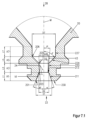
プラズマアークトーチ用の、図1において断面図(上側)および断面詳細図(下側)において示されたノズル2は、全長L20、内面21および外面23、前端部22および後端部28ならびに前端部22に設けられたノズル開口24を備えた、長手方向軸線Mに沿って延びる本体20を含んでいる。さらに本体20は、前端部22において溝238を有している。この溝238内には、ノズル2がプラズマアークトーチ内に組み込まれている場合に、ノズル2とノズルキャップ5との間の室(図16を参照)をシールするための円形リング240(図16を参照)が位置する。
ノズル2の本体20の内面21は、前端部22(ノズル開口24)から、長手方向軸線Mに沿って延びる第1の区分A1を有している。この第1の区分A1は、まず、たとえば1.0mmである長さL1にわたって、その内面211と長手方向軸線Mとの間の、ここでは約19°である角度αで円錐状に先細りする。次いでノズル2の本体20の内面21は、長手方向軸線Mの方向の突出部を有している。この突出部は、その内面213と長手方向軸線Mとの間で、ここではたとえば90°である角度βを形成している。ノズル開口24は、直接に前端部22において、ここではたとえば1.9mmである直径D1を有していて、第1の区分A1の内面211の円錐状の領域の端部において、ここではたとえば1.2mmである直径D2を有している。次いで、ここでは0.1mmである突出部によって、ノズル開口24の直径は、ここではたとえば1.0mmである直径D3に減じられる。
The
第1の区分A1には、直径D3およびたとえば1.0mmである長さL3を備えた第2の区分A3が直接に接続する。この第2の区分A3は、円筒状の内面220を有している。この第2の区分A3には、第3の区分A5が接続する。第3の区分A5の内面224は、その内面224と長手方向軸線Mとの間の、ここではたとえば45°である角度δで、直径D3から、ここではたとえば2.8mmである直径D7へと拡開する。この第3の区分A5は、長手方向軸線Mに沿って、ここではたとえば0.9mmである長さL5にわたって延びている。この第3の区分A5には、直径D7を有する第4の区分A7が接続する。この第4の区分A7は、たとえば1.2mmの長さL7を備えた円筒状の内面227を有している。この第4の区分A7には、円錐状に拡開する別の領域が接続する。
Directly connected to the first section A1 is a second section A3 with a diameter D3 and a length L3, for example 1.0 mm. This second section A3 has a cylindrical
D1=1.9mmおよびD3=1.0mmでは、直径D1は、直径D3の1.9倍である。直径D1は、直径D3よりも0.9mm大きい。 With D1=1.9 mm and D3=1.0 mm, the diameter D1 is 1.9 times the diameter D3. Diameter D1 is 0.9 mm larger than diameter D3.
図12に図示されている、ノズル開口24の前端部22において直接に第1の区分A1の直径D1によって長手方向軸線Mに対して垂直方向に形成される面積A10は、約2.8mm2であり、
[A10=3.141/4・D12]
により求められる。
The area A10 formed perpendicularly to the longitudinal axis M by the diameter D1 of the first section A1 directly at the
[A10=3.141/4·D1 2 ]
required by
図13に図示されている、ノズル開口24の第2の区分A3の最小の直径D3により長手方向軸線Mに対して垂直方向に形成される面積A30は、約0.8mm2であり、
[A30=3.141/4・D32]
により求められる。
the area A30 formed perpendicular to the longitudinal axis M by the smallest diameter D3 of the second section A3 of the
[A30=3.141/4·D3 2 ]
required by
したがって、面積A10は、面積30の約3.6倍である。 Area A10 is therefore approximately 3.6 times area 30. FIG.
第1の区分A1の長さL1=1.0mmおよび第2の区分A3の長さL3=1.0mmは、L1/L3=1の比を形成する。第2の区分A3の長さL3と直径D3との商は、同様に1である。さらに、直径D1=1.9mmは、直径D7=2.8mmよりも小さい。 The length L1=1.0 mm of the first section A1 and the length L3=1.0 mm of the second section A3 form the ratio L1/L3=1. The quotient of the length L3 and the diameter D3 of the second section A3 is also unity. Furthermore, diameter D1=1.9 mm is smaller than diameter D7=2.8 mm.
図1は、さらに、前端部22において直径D1を有するノズル開口24の本体エッジ201と、第1の区分A1から、直径D3を有するノズル開口24の第2の区分A3への移行部の本体エッジ203との間に延びる仮想の接続ラインV1を示している。この接続ラインV1と、長手方向軸線Mにより形成される角度α1は、約24°である。
FIG. 1 also shows a
第1の区分A1のノズル開口24の、内面211および内面213により形成される容積V10は、約1.9mm3であり、
[V10=3.141・L1/3・((D1/2)2+(D1/2・D2/2)+(D3/2)2]
により算出される。
the volume V10 formed by the
[V10=3.141·L1/3·((D1/2) 2 +(D1/2·D2/2)+(D3/2) 2 ]
Calculated by
第2の区分A3のノズル開口24の、内面220により形成される容積V30は、約0.8mm3であり、[V30=3.141・(D3/2)2・L3]により算出される。したがって、V10は、容積V30の約1.9倍大きい。
The volume V30 formed by the
図2は、図1に示したノズルに類似するノズル2の別の実施例の詳細図を示している。このノズル2は、図1に示したノズルとは、その内面213と長手方向軸線Mとの間で角度β=100°を形成する、長手方向軸線Mの方向の突出部により、異なっている。
FIG. 2 shows a detailed view of another embodiment of
図3は、図1に示したノズルに類似するノズル2の別の実施例の詳細図を示している。このノズル2は、図1に示したノズルとは、その内面213と長手方向軸線Mとの間で角度β=60°を形成する、長手方向軸線Mの方向の突出部により、異なっている。
FIG. 3 shows a detailed view of another embodiment of
図4は、図1に示したノズルに類似するノズル2の別の実施例の詳細図を示している。このノズル2は、図1に示したノズルとは、第1の区分A1が前端部から凹状に先細りする内面211を有していることにより、異なっている。前端部22において直径D1を有するノズル開口24の本体エッジ201と、第1の区分A1から直径D3を有するノズル開口24の第2の区分A3への移行部における本体エッジ203との間に延びる仮想の接続ラインV1は、長手方向軸線Mと、たとえば約32°である角度α1を形成する。直径D1は、ここではたとえば2.4mmであり、直径D3=1.4mmであり、したがって直径D1は、直径D3の約1.7倍である。
FIG. 4 shows a detailed view of another embodiment of
図12に図示されている、ノズル開口24の前端部22において直接に第1の区分A1の直径D1によって長手方向軸線Mに対して垂直方向に形成される面積A10は、約4.5mm2であり、
[A10=3.141/4・D12]
により求められる。
The area A10 formed perpendicularly to the longitudinal axis M by the diameter D1 of the first section A1 directly at the
[A10=3.141/4·D1 2 ]
required by
図13に図示されている、ノズル開口24の第2の区分A3の最小の直径D3により長手方向軸線Mに対して垂直方向に形成される面積A30は、約1.5mm2であり、
[A30=3.141/4・D32]
により求められる。
the area A30 formed perpendicular to the longitudinal axis M by the smallest diameter D3 of the second section A3 of the
[A30=3.141/4·D3 2 ]
required by
したがって、面積A10は、面積A30の約2.9倍である。 Therefore, the area A10 is approximately 2.9 times the area A30.
長さL1は、たとえば0.8mmであり、長さL3は、たとえば1.2mmであり、したがって、長さL1は、長さL3の0.67倍である。 The length L1 is, for example, 0.8 mm and the length L3 is, for example, 1.2 mm, so the length L1 is 0.67 times the length L3.
第2の区分A3の長さL3=1.2mmと直径D3=1.4mmとの商は、0.86である。さらに、直径D1=2.4mmは、直径D7=3.0mmよりも小さい。 The quotient of the length L3=1.2 mm and the diameter D3=1.4 mm of the second section A3 is 0.86. Furthermore, diameter D1=2.4 mm is smaller than diameter D7=3.0 mm.
第1の区分A1のノズル開口24の、内面211により形成される容積V10は、約2.3mm3である。第2の区分A3のノズル開口24の、内面220により形成される容積V30は、約1.8mm3である。したがって、容積V10は、容積V30の約1.3倍大きい。
The volume V10 formed by the
図5は、図4に示したノズルに類似するノズル2の別の実施例の詳細図を示している。このノズル2は、図1に示したノズルとは、第1の区分A1が、前端部から凸状に先細りする内面211を有していることにより、異なっている。前端部22において直径D1を有するノズル開口24の本体エッジ201と、第1の区分A1から直径D3を有するノズル開口24の第2の区分A3への移行部における本体エッジ203との間に延びる仮想の接続ラインV1は、長手方向軸線Mと、たとえば約32°の角度α1を形成する。直径D1は、ここではたとえば2.4mmであり、直径D3は、1.4mmであり、したがって直径D1は、直径D3の約1.7倍である。長さL1は、たとえば0.8mmであり、長さL3は、たとえば1.2mmであり、したがって長さL1は、長さL3の約0.67倍である。
FIG. 5 shows a detailed view of another embodiment of
第2の区分A3の長さL3=1.2mmと直径D3=1.4mmとの商は、約0.86である。さらに直径D1=2.4mmは、直径D7=3.0mmよりも小さい。 The quotient of the length L3=1.2 mm and the diameter D3=1.4 mm of the second section A3 is approximately 0.86. Furthermore, diameter D1=2.4 mm is smaller than diameter D7=3.0 mm.
面積A10および面積A30には、図4の例示的な記載が当てはまる。容積V10および容積V30の記載にも同様のことが当てはまる。 For area A10 and area A30 the exemplary description of FIG. 4 applies. The same applies to the description of volume V10 and volume V30.
たとえば凸状の内面211が連続的にまたは「流線的」に面230に移行していることによって、本体エッジ201自体が一義的に確認できない場合、ノズル2の後端部28から見て、内面211に接する接線Tと長手方向軸線Mとの間で65°の角度α2が上回られると、その内面の領域が本体エッジであると考えられる。したがって仮想の接続ラインV1は、この領域と本体エッジ203との間で延びている。このことは、図5.1に示されている。
If the
図6は、図4に示したノズルに類似するノズル2の別の実施例を示している。このノズル2は、図4に示したノズルとは、第1の区分A1が、前端部から段階的に先細りした内面211を有していることにより、異なっている。前端部22において直径D1を有するノズル開口24の本体エッジ201と、第1の区分A1から直径D3を有するノズル開口24の第2の区分A3への移行部における本体エッジ203との間に延びる仮想の接続ラインV1は、長手方向軸線Mとたとえば約32°の角度α1を形成する。直径D1は、ここではたとえば2.4mmであり、直径D3=1.4mmであるので、直径D1は、直径D3の1.7倍である。第1の区分A1の長さL1=0.8mmと、第2の区分A3の長さL3=1.2mmとは、L1/L3=0.67の比を形成する。第2の区分A3の長さL3と直径D3との商は、約0.86である。直径D7は、たとえば3.0mmである。したがって、直径D1=2.4mmは、直径D7=3.0mmよりも小さい。
FIG. 6 shows another embodiment of a
面積A10および面積A30には、図4の例示的な記載が当てはまる。容積V10および容積V30の記載にも同様のことが当てはまる。 For area A10 and area A30 the exemplary description of FIG. 4 applies. The same applies to the description of volume V10 and volume V30.
図7は、図1に示したノズルに類似するノズル2の別の実施例の詳細図を示している。サイズは、図1に示したサイズと同一である。単に第2の区分A3が、ノズル2の前端部22から見てその内面220が長手方向軸線Mに対してたとえば5°の角度γで拡開するように、構成されている。この拡開は、ここでは円錐状に行われている。したがって、区分A5への移行部における区分A3の直径D31は、ノズル開口24の第1の区分A1から第2の区分A3への移行部における直径D3よりも大きい。
FIG. 7 shows a detailed view of another embodiment of
図7.1は、図7に示したノズルに類似するノズル2の別の実施例の詳細図を示している。サイズは、図7に示したサイズと同一である。単に第2の区分A3が、ノズル2の前端部22から見て、その内面220が凹状に拡開するように、構成されている。第1の区分A1から第2の区分A3への移行部における本体エッジ203と、第2の区分A3から第3の区分A5への移行部における本体エッジ205との間に延びる仮想の接続ラインV3は、長手方向軸線Mと、たとえば約5°の角度γ1を形成する。したがって、この実施例では、区分A5への移行部における区分A3の直径D31は、ノズル開口24の第1の区分A1から第2の区分A3への移行部における直径D3よりも大きい。
FIG. 7.1 shows a detailed view of another embodiment of
図7.2は、図7.1に示したノズルに類似するノズル2の別の実施例の詳細図を示している。サイズは、図7.1に示したサイズと同一である。単に、第2の区分A3が、ノズル2の前端部22から見て、その内面220が凹状ではなく凸状に拡開するように、構成されている。
Figure 7.2 shows a detailed view of another embodiment of a
図8は、図1に示したノズルに類似するノズル2の別の実施例の詳細図を示している。第2の区分A3は、ノズル2の前端部22から見て、その内面220が、長手方向軸線Mに対してたとえば175°の角度γで先細りするように、構成されている。この先細りは、ここでは円錐状に行われる。したがって、第1の移行部A1から第2の移行部A3への移行部における第2の区分A3の直径D32=1.17mmは、ノズル開口24の第2の区分A3から第3の区分A5への移行部における直径D3=1mmよりも大きい。直径D2は、1.4mmであり、直径D1=2.1mmである。角度αは、19°であり、角度α1は、21°である。
FIG. 8 shows a detailed view of another embodiment of
図8.1は、図8に示したノズルに類似するノズル2の別の実施例の詳細図を示している。しかし、第2の区分A3は、ノズル2の前端部22から見て、その内面220が凸状に先細りするように、構成されている。第1の区分A1から第2の区分A3への移行部における本体エッジ203と、第2の区分A3から第3の区分A5への移行部における本体エッジ205との間に延びる仮想の接続ラインV3は、長手方向軸線Mと、たとえば約175°の角度γ1を形成する。したがって、第1の区分A1から第2の区分A3への移行部における第2の区分A3の直径D32=1.17mmは、ノズル開口24の第2の区分A3から第3の区分A5への移行部における直径D3=1mmよりも大きい。直径D2は、1.4mmであり、直径D1=2.1mmである。角度αは、この実施例では19°であり、角度α1は、この実施例では21°である。
FIG. 8.1 shows a detailed view of another embodiment of
図8.2は、図8.1に示したノズルに類似するノズル2の別の実施例の詳細図を示している。しかし、第2の区分A3は、ノズル2の前端部22から見て、その内面220が凸状ではなく、凹状に先細りするように、構成されている。
Figure 8.2 shows a detailed view of another embodiment of a
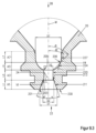
図9は、図1に示したノズルに類似するノズル2の別の実施例の詳細図を示している。サイズは、図1に示したサイズと同一である。第3の区分A5は、その表面224と、長手方向軸線Mとの間でたとえば80°の角度δを有していて、拡開している。しかし、このノズルは、その外側輪郭が別の実施例の外側輪郭とは異なるノズルである。このノズルは、たとえばノズル用の液体冷却を有しないプラズマトーチ、レーザヘッドまたはプラズマレーザヘッドにおける使用のために適している。この実施例では、ノズルは、円形リングを収容するための溝238を有していない。対応するアセンブリは、図18に示されている。
FIG. 9 shows a detailed view of another embodiment of
図9.1は、図9に示したノズルに類似するノズル2の別の実施例の詳細図を示している。サイズは、図9に示したサイズと同一である。単に第3の区分A5が、ノズル2の前端部から見て、その内面224が凹状に拡開するように、構成されている。第2の区分A3から第3の区分A5への移行部における本体エッジ205(この場合、「内側コーナ」または「本体内側エッジ」と呼ぶことができる)と、第3の区分A5から第4の区分A7への移行部における本体エッジ206(この場合、「内側コーナ」または「本体内側エッジ」とも呼ぶことができる)との間に延びる仮想の接続ラインV4は、長手方向軸線Mと、たとえば約45°の角度δ1を形成する。
FIG. 9.1 shows a detailed view of another embodiment of
たとえば凹状の内面が連続的または「流線的」に内面227に移行していることによって、本体エッジ206自体が一義的に確認できない場合、ノズルの前端部22から見て、内面224に接する接線Tと長手方向軸線Mとの間で20°の角度δ2が下回られると、その内面の領域206が本体エッジ206であると考えられる。このことは図9.3に示されている。
If the
図9.2は、図9に示したノズルに類似するノズル2の別の実施例の詳細図を示している。サイズは、図9に示したサイズと同一である。単に第3の区分A5が、ノズル2の前端部22から見て、その内面224が凸状に拡開するように、構成されている。第2の区分A3から第3の区分A5への移行部における本体エッジ205と、第3の区分A5から第4の区分A7への移行部における本体エッジ206との間に延びる仮想の接続ラインV4は、長手方向軸線Mと、たとえば約45°の角度δ1を形成する。
FIG. 9.2 shows a detailed view of another embodiment of
たとえば凹状の内面224が連続的または「流線的」に面227に移行していることによって、本体エッジ206自体が一義的に確認できない場合、ノズル2の前端部22から見て、内面224に接する接線Tと長手方向軸線Mとの間で20°の角度δ2が下回られると、その内面の領域が、本体エッジ206であると考えられる。仮想の接続ラインV4は、この領域206と本体エッジ205との間に延びている。このことは、凹状に拡開する第3の区分A5を示す図9.3に示されている。
If the
図10は、図1に示したノズルに類似するノズル2の別の実施例の詳細図を示している。サイズは、図1に示したサイズと同一である。第4の区分A7は、その内側の表面227と長手方向軸線Mとの間で、たとえば5°の角度εを有していて、拡開している。
FIG. 10 shows a detailed view of another embodiment of
図11は、図1に示したノズルに類似するノズル2の別の実施例の詳細図を示している。サイズは、図1に示したサイズと同一である。第4の区分A7は、その内側の表面227と長手方向軸線Mとの間で、たとえば175°の角度εを有していて、先細りしている。
FIG. 11 shows a detailed view of another embodiment of
それぞれの区分A1,A3,A5およびA7の間で移行部においてたとえば0.1mmの大きさのR部が配置されていてよい。 Between the respective sections A1, A3, A5 and A7 there may be arranged radiuses with a size of, for example, 0.1 mm at the transitions.
図12、図13および図13aは、ノズル開口24の、直径D1,D2およびD3により長手方向軸線Mに対して垂直方向に形成される面積A10,A20,A30およびA31を示している。図1~図11の実施例では、面積A10は面積A30の最小で1.7倍大きく、有利には最小で2.1倍大きい。さらに面積A10は、面積A30よりも最大で4倍大きく、有利には最大で3.7倍大きい。
Figures 12, 13 and 13a show the areas A10, A20, A30 and A31 of the
図14は、第1の区分A1のノズル開口24の、内面211および内面213により取り囲まれる容積V10を示し、図15は、第2の区分A3のノズル開口24の、内面220により取り囲まれる容積V30を示している。これらの実施例では、容積V10は容積V30よりも大きく、有利には最小で1.3倍大きく、かつ/または最大で2.5倍大きく、有利には最大で2.2倍大きい。
FIG. 14 shows the volume V10 of the
図16は、プラズマトーチの構成部材であってよいプラズマトーチヘッド1の断面図を示している。 FIG. 16 shows a cross-sectional view of a plasma torch head 1 which may be a component of a plasma torch.
プラズマトーチヘッド1は、トーチ本体8、電極3、本発明に係るノズル2、ノズルキャップ5、ノズル2を収容するノズルホルダ81およびノズル2をノズルホルダ81内に位置固定するノズル保護キャップ6を有している。
The plasma torch head 1 has a torch body 8, an
図16では、例示的に図1に示したノズル2が使用されている。
In FIG. 16, the
電極3の前端部33は、ノズル2の内室に突入している。さらに、電極3とノズル2との間には、プラズマガスまたはプロセスガスPG用のガスガイド部4が位置している。ガスガイド部4は、プラズマガスまたはプロセスガスを導き、ここではたとえば半径方向で電極3とノズル2との間の内室内にガイドする開口41を有している。半径方向線に対するずれにより、プラズマガスまたはプロセスガスPGを回転させることができる。ガスガイド部4は、電極3およびノズル2を互いに電気絶縁する。電極3は、内部で液体冷却されていてよいが、これはこの図面には図示されていない。冷却媒体(WV-送り流、WR-戻し流)は、ノズル2とノズルキャップ5との間の室51内を流れ、ノズル2およびノズルキャップ5を冷却する。
A
ノズルの前端部22は、ノズル保護キャップ6により少なくとも部分的に覆われている。ノズル保護キャップ6は、ノズル開口24に長手方向軸線M上で整合する開口64を有している。ノズルキャップ5と、ノズル2の前端部22と、ノズル保護キャップ6との間には、二次ガスSGのためのガスガイド部7が位置している。ガスガイド部7は、二次ガスSGを導き、ここではたとえば半径方向で、ノズルキャップ5と、ノズル2の前端部22と、ノズル保護キャップ6との間の内室61内にガイドする開口71を有している。半径方向線に対するずれにより、プラズマガスおよびプロセスガスPGは回転させられる。ガスガイド部7は、ノズルキャップ5とノズル保護キャップ6とを互いに電気的に絶縁している。
The nozzle
プラズマガスまたはプロセスガスPGは、アークによるプラズマ切断時にイオン化され、最終的にノズル開口24と、ノズル保護キャップの開口64から流出する。
The plasma gas or process gas PG is ionized during arc plasma cutting and finally flows out of the
図17および図17aにはそれぞれ、図16に示したプラズマトーチヘッドの構成部材である、本発明の特別な実施形態によるアセンブリの断面詳細図が示されている。しかし、このアセンブリは、同様にレーザ切断ヘッドまたはプラズマレーザ切断ヘッドの構成部材であってもよい。特許請求されているアセンブリは、ノズル2およびノズル保護キャップ6を含んでいる。さらに、ノズルキャップ5およびガスガイド部7が示されている。
17 and 17a each show a cross-sectional detail view of an assembly according to a particular embodiment of the invention, which is a component of the plasma torch head shown in FIG. However, the assembly may likewise be a component of a laser or plasma laser cutting head. The claimed assembly includes
ノズル2の前端部は、ノズル保護キャップ6により少なくとも部分的に覆われている。ノズル保護キャップ6は、ノズル開口24に長手方向軸線M上で整合する開口64を有している。ノズルキャップ5と、ノズル2の前端部22と、ノズル保護キャップ6との間には、二次ガスSGのためのガスガイド部7が位置している。ガスガイド部7は、二次ガスSGを導き、ここではたとえば半径方向で、ノズルキャップ5と、ノズル2の前端部22と、ノズル保護キャップ6との間の内室61内にガイドする開口71を有している。半径方向線に対するずれにより、プラズマガスおよびプロセスガスPGは回転させられる。ガスガイド部7は、ノズルキャップ5とノズル保護キャップ6とを互いに電気的に絶縁している。
The front end of
ノズル2は、たとえば図1によれば、直径D1=1.9mmおよび直径D3=1.0mmを有している。ノズル保護キャップ6は、3.0mmの最小の直径D6を有する開口64を有している。直径D6は、直径D1および直径D3よりも大きい。直径D6により長手方向軸線に対して垂直方向に形成される面積A60は、直径D1により形成される面積A10および直径D3により形成される面積A30よりも大きい。
The
ノズル2の角度αは、この実施例では19°であり、ノズル2の角度α1は、この実施例では24°である。前方から見て円錐状に先細りする内面211をノズルの前端部22の方向に、つまりノズル2から出るように仮想的に延長すると、この内面211は仮想のラインV2を形成する。この仮想のラインV2は、直径D6を有する開口64により形成される、ノズル保護キャップ6の本体エッジ65に接触しない。同様のことは、前端部22におけるノズル開口24の本体エッジ201と、第1の区分A1から第2の区分A3への移行部における本体エッジ203との間の、延長された仮想の接続ラインV1にも当てはまる。
The angle α of the
ノズル保護キャップ6の開口64の面積A60および直径D6は、ノズル2の、ノズル保護キャップ6に向かって延長された仮想の接続ラインV1およびV2により投影される仮想の面積A70およびA80または直径よりも大きい。
The area A60 and diameter D6 of the
さらに、ノズル2の前端部22の外面と、ノズル保護キャップ6の内面との間の最短の間隔の長さL61は、たとえば0.7mmであり、したがってノズル2の第1の区分A1の長さL1=1.0mmおよび第2の区分A3の長さL3=1.0mmよりも小さく、2mmであるL1とL3との合計よりも小さい。
Furthermore, the shortest distance length L61 between the outer surface of the
図18および図18aには、本発明の特別な実施形態によるアセンブリの断面詳細図が示されている。この特許請求されたアセンブリは、図9に示したノズル2と、ノズル保護キャップ6とを含んでいる。さらに、ガスガイド部7が示されている。このアセンブリは、プラズマトーチヘッド、レーザ切断ヘッドまたはプラズマレーザ切断ヘッドの構成部材であってよい。
Figures 18 and 18a show cross-sectional details of an assembly according to a particular embodiment of the invention. This claimed assembly includes the
図17とは異なり、ノズル2は、ノズルキャップにより取り囲まれていない。ノズル2は、直径D1=1.9mmおよびD3=1.0mmを有している。ノズル保護キャップ6は、3.0mmの最小の直径D6を有する開口64を有している。直径D6は、ノズル2の直径D1および直径D3よりも大きい。直径D6により長手方向軸線に対して垂直方向に形成される面積A60は、直径D1により形成される面積A10および直径D3により形成される面積A30よりも大きい。
Unlike FIG. 17,
ノズルの前端部22は、ノズル保護キャップ6により少なくとも部分的に覆われている。ノズル保護キャップ6は、ノズル開口24に長手方向軸線M上で整合する開口64を有している。ノズル2とノズル保護キャップ6との間には、二次ガスSGのためのガスガイド部7が位置している。ガスガイド部7は、二次ガスSGを導き、ここではたとえば半径方向で、ノズル2と、ノズル保護キャップ6との間の内室61内にガイドする開口71を有している。半径方向線に対するずれにより、プラズマガスPGは回転させられる(図21を参照)。ガスガイド部7は、ノズル2とノズル保護キャップ6とを互いに電気的に絶縁している。
The nozzle
ノズル2の角度αは、この実施例では19°であり、ノズル2の角度α1は、この実施例では24°である。仮想的に、前方から見て円錐状に先細りする内面をノズル2の前端部22の方向に、つまりノズル2から出るように延長すると、この内面は、仮想のラインV2を形成する。この仮想のラインV2は、直径D6を有する開口64により形成される、ノズル保護キャップ6の本体エッジ65に接触しない。同様のことは、前端部22におけるノズル開口24の本体エッジ201と、第1の区分A1から第2の区分A3への移行部における本体エッジ203の間の延長された仮想の接続ラインV1にも当てはまる。
The angle α of the
ノズル保護キャップ6の開口64の面積A60および直径D6は、ノズル2の、ノズル保護キャップ6に向かって延長された仮想の接続ラインV1およびV2により投影される仮想の面積A70およびA80または直径よりも大きい。
The area A60 and diameter D6 of the
さらに、ノズル2の前端部22の外面と、ノズル保護キャップ6の内面との間の最短の間隔の長さL61は、たとえば0.7mmであり、したがってノズル2の第1の区分A1の長さL1=1.0mmおよび第2の区分A3の長さL3=1.0mmよりも小さく、2mmであるL1とL3との合計よりも小さい。
Furthermore, the shortest distance length L61 between the outer surface of the
図19には、図16に示したプラズマトーチヘッドの構成部材である、本発明の特別な実施形態によるアセンブリの断面詳細図が示されている。特許請求されたアセンブリは、本発明の特別な実施形態によるノズル2と、電極3とを含んでいる。さらに、ガスガイド部4が示されている。
FIG. 19 shows a cross-sectional detail view of an assembly according to a particular embodiment of the invention, which is a component of the plasma torch head shown in FIG. The claimed assembly includes a
電極3の前端部33は、ノズル2の内室に突入している。さらに、電極3とノズル2との間には、プラズマガスPGのためのガスガイド部4が位置している。ガスガイド部4は、プラズマガスを導き、ここではたとえば半径方向で電極3とノズル2との間の内室内にガイドする開口41を有している。半径方向線に対するずれにより、プラズマガスPGを回転させることができる。ガスガイド部4は、電極3とノズル2とを互いに電気的に絶縁している。電極3の前端部33と、ノズル2のノズル開口24の第3の区分A5から第2の区分A3への移行部との間の間隔L13は、6mmの長さであり、第1の区分A1の長さL1と、第2の区分A3の長さL3とは、それぞれ1mmである。したがって、長さL1と長さL3との合計は、2mmである。したがって、L1,L3も、L1とL3との合計も、間隔L13の長さよりも短い。
A
図20には、例示的に二次ガスSGのためのガスガイド部7が示されている。中央の断面図からは、開口71が、長手方向軸線Mに対する半径方向線に対してずらされて配置されていることが明らかである。したがって、開口71を通って流れるガスは、回転させられる。しかし回転は、開口の別の空間的な配向によって、たとえば長手方向軸線Mに対する傾斜によっても形成することができる。
FIG. 20 shows the
図21には、例示的にプラズマガスまたはプロセスガス用のガスガイド部4が示されている。中央の断面図から、開口41が、長手方向軸線Mに対する半径方向線に対してずらされて配置されていることが判る。したがって、開口41を通って流れるガスは、回転させられる。しかし回転は、開口の別の空間的な配向によって、たとえば長手方向軸線Mに対する傾斜によっても形成することができる。
FIG. 21 shows, by way of example, a
上述の説明は、プラズマ切断用もしくはプラズマトーチヘッド用のノズルに合わせたものである。プラズマトーチヘッドは、プラズマトーチ切断ヘッドであってよい。しかし説明は、同様の形式で、レーザ切断用もしくはレーザ切断ヘッド用のノズルならびにプラズマレーザ切断用もしくはプラズマレーザ切断ヘッド用のノズルにも当てはまる。 The above description applies to nozzles for plasma cutting or plasma torch heads. The plasma torch head may be a plasma torch cutting head. However, the explanations apply in an analogous manner to nozzles for laser cutting or laser cutting heads as well as nozzles for plasma laser cutting or plasma laser cutting heads.
上述の説明、図面ならびに請求項において開示される本発明の特徴は、単独でも任意の組み合わせにおいても、種々異なる実施形態で本発明を実現するために重要であり得る。
以下、本発明の好ましい実施形態を項分け記載する。
実施形態1
プラズマトーチヘッド、レーザ切断ヘッドまたはプラズマレーザ切断ヘッド用のノズル(2)であって、長手方向軸線Mを有する本体(20)と、前端部(22)と、後端部(28)と、前記前端部(22)に設けられたノズル開口(24)とを含み、前記前端部(22)の前記ノズル開口(24)が、前記前端部から見て、縦断面で少なくとも以下の区分、すなわち
-前記長手方向軸線Mに沿って延び、前記後端部(28)に向かう方向で先細りする第1の区分A1であって、内面(211)と、前記前端部(22)に設けられた本体エッジ(201)とを備えた第1の区分A1と、
-前記長手方向軸線Mに沿って延びる第2の区分A3であって、内面(220)と、前記第1の区分A1から前記第2の区分A3への移行部に設けられた本体エッジ(203)とを備えた第2の区分A3と
を含んでいて、
前記前端部(22)における前記ノズル開口(24)の前記本体エッジ(201)と、前記第1の区分A1から前記第2の区分A3への前記移行部に設けられた前記本体エッジ(203)との間の仮想の接続ラインV1と、前記長手方向軸線Mとが、15°~40°の範囲、好適には20°~38°の範囲、さらに好適には20°~35°の範囲、最も好適には25°~35°の範囲の角度α1を形成し、かつ/または前記第1の区分A1の前記内面(211)と、前記長手方向軸線Mとが、10°~30°の範囲、好適には12°~30°の範囲、さらに好適には14°~25°の範囲、さらに好適には15°~20°の範囲、最も好適には17°~20°の範囲の角度αを形成し、かつ
前記第1の区分A1から前記第2の区分A3への前記移行部に設けられた前記本体エッジ(203)と前記第2の区分A3から第3の区分A5への移行部に設けられた本体エッジ(205)との間の仮想の接続ラインV3と、前記長手方向軸線Mとが、0°~8°の範囲、好適には5°の角度γ1を形成して前記後端部(28)に向かう方向で拡開するか、または172°~180°の範囲、好適には175°の角度γ1を形成して前記後端部(28)に向かう方向で先細りするか、または前記長手方向軸線Mに対して平行に延びる、または
前記第2の区分A3の前記内面(220)が、0°~8°の範囲、好適には5°の角度γで前記後端部(28)に向かう方向で拡開するか、または172°~180°の範囲、好適には175°の角度で前記後端部(28)の方向に向かう方向で先細りするか、または前記長手方向軸線Mに対して平行に延びる、
ノズル(2)。
実施形態2
前記第1の区分A1から前記第2の区分A3への前記移行部において、または該移行部の手前または直前に、前記長手方向軸線Mに対して45°~120°の範囲、好適には60°~110°の範囲、さらに好適には80°~100°の範囲、さらに好適には85°~95°の範囲の角度βで延び、最も好適には垂直方向に延びる、少なくとも1つの別の内面(213)が位置している、実施形態1記載のノズル(2)。
実施形態3
前記前端部(22)から見て、前記第2の区分A3の背後に、前記長手方向軸線Mに沿って延び、前記後端部(28)に向かう方向で拡開する、内面(224)を備えた第3の区分A5が存在している、実施形態1または2記載のノズル(2)。
実施形態4
前記第3の区分(A5)の前記内面(224)が、前記長手方向軸線Mに沿って前記後端部(28)に向かう方向で拡開する少なくとも1つの領域を有していて、該領域の内面と、前記長手方向軸線Mとが、30°~90°の範囲、好適には40°~75°の範囲の角度δを形成する、実施形態3記載のノズル。
実施形態5
前記前端部(22)から見て、前記第3の区分A5の背後に、内面(227)を備えた第4の区分A7が存在していて、前記第2の区分A3から前記第3の区分A5への前記移行部に設けられた前記本体エッジ(205)と、前記第3の移行部A5から前記第4の区分A7への移行部に設けられた本体エッジ(206)との間の仮想の接続ラインV4と、前記長手方向軸線Mとが、30°~90°の範囲、好適には40°~75°の範囲の角度δ1を形成し、かつ/または前記第3の区分A5の前記内面(224)と、前記長手方向軸線Mとが、30°~90°の範囲、好適には40°~75°の範囲の角度δを形成する、実施形態3記載のノズル。
実施形態6
前記前端部(22)から見て、前記第3の区分A5の背後に、内面(227)を備えた第4の区分A7が存在していて、該第4の区分A7の前記内面(227)が、前記長手方向軸線Mに対して0°~10°の範囲、好適には5°の角度εで前記後端部(28)に向かう方向で拡開するか、または170°~180°の範囲、好適には175°の角度で前記後端部(28)に向かう方向で先細りするか、または前記長手方向軸線Mに対して平行に延びる少なくとも1つの領域を有している、または
前記第4の区分A7の前記内面(227)が、前記長手方向軸線Mに対して、0°~10°の範囲、好適には5°の角度εで前記後端部(28)に向かう方向で拡開するか、または170°~180°の範囲、好適には175°の角度で前記後端部(28)に向かう方向で先細りするか、または前記長手方向軸線Mに対して平行に延びる、実施形態3記載のノズル(2)。
実施形態7
前記第1の区分A1が、前記前端部(22)から見て、円錐状、凸状または凹状に先細りする、かつ/または
前記第2の区分A3が、円錐状、凸状または凹状に先細りするかまたは拡開する、かつ/または
前記第3の区分A5が、円錐状、凸状または凹状に拡開する、かつ/または
前記第4の区分A7が、円錐状、凸状または凹状に先細りするかまたは拡開する、
実施形態1から6までのいずれか1項記載のノズル(2)。
実施形態8
前記第1の区分A1が、前記前端部(22)から見て、連続的または非連続的に先細りする、かつ/または
前記第2の区分A3が、連続的または非連続的に先細りするかまたは拡開する、かつ/または
前記第3の区分A5が、連続的または非連続的に拡開する、かつ/または
前記第4の区分A7が、連続的または非連続的に先細りするかまたは拡開する、
実施形態1から6までのいずれか1項記載のノズル(2)。
実施形態9
前記第1の区分A1が、前記前端部(22)から見て、段階的に先細りする、かつ/または
前記第2の区分A3が、段階的にかつ/または前記長手方向軸線Mに対して垂直方向に先細りするかまたは拡開する、かつ/または
前記第3の区分A5が、段階的にかつ/または前記長手方向軸線Mに対して垂直方向に拡開する、かつ/または
前記第4の区分A7が、段階的にかつ/または前記長手方向軸線Mに対して垂直方向に先細りするかまたは拡開する、
実施形態1から6までのいずれか1項記載のノズル(2)。
実施形態10
前記第1の区分A1および前記第2の区分A3、または
前記第2の区分A3および前記第3の区分A5、または
前記第3の区分A5および前記第4の区分A7、または
前記第1の区分A1、前記第2の区分A3および前記第3の区分A5、または
前記第2の区分A3、前記第3の区分A5および前記第4の区分A7、または
前記第1の区分A1、前記第2の区分A3、前記第3の区分A5および前記第4の区分A7が、互いに直接に続いている、実施形態1から9までのいずれか1項記載のノズル(2)。
実施形態11
前記第1の区分A1の最大の横断面積A10、および/または前記ノズル開口(24)の、該ノズル開口(24)の前記前端部(22)に直接に位置する最大の横断面積A10が、前記第2の区分A3の最小の横断面積A30,A31および/または前記ノズル開口(24)の最小の横断面積A30,A31よりも最小で1.7倍、好適には2.1倍大きく、かつ/または最大で4.0倍、好適には3.7倍大きい、実施形態1から10までのいずれか1項記載のノズル(2)。
実施形態12
前記第1の区分A1の最大の直径D1、および/または前記ノズル開口(24)の、該ノズル開口(24)の前記前端部に直接に位置する最大の直径D1が、前記第2の区分A3の最小の直径D3および/または前記ノズル開口(24)の最小の直径D3よりも最小で1.3倍、好適には1.45倍大きく、かつ/または最大で2.1倍、好適には1.9倍大きい、実施形態1から11までのいずれか1項記載のノズル(2)。
実施形態13
前記第1の区分A1の最大の直径D1、および/または前記ノズル開口(24)の、該ノズル開口(24)の前記前端部(22)に直接に位置する最大の直径D1が、前記第2の区分A3の最小の直径D3および/または前記ノズル開口(24)の最小の直径D3よりも最小で0.5mm、好適には0.6mm大きく、かつ/または最大で1.2mm、好適には1.0mm大きい、実施形態1から12までのいずれか1項記載のノズル(2)。
実施形態14
前記第1の区分A1の、前記長手方向軸線Mに沿って延びる長さL1と、前記第2の区分A3の、前記長手方向軸線Mに沿って延びる長さL3との商L1/L3が、0.5~1.2、好適には0.65~1である、実施形態1から13までのいずれか1項記載のノズル(2)。
実施形態15
前記第3の区分A5の、前記長手方向軸線Mに沿って延びる長さL5と、前記第1の区分A1の、前記長手方向軸線Mに沿って延びる長さL1との商L5/L1が、1.5以下であり、好適には1.25以下である、実施形態1から14までのいずれか1項記載のノズル(2)。
実施形態16
前記第3の区分A5の、前記長手方向軸線Mに沿って延びる長さL5と、前記第2の区分A3の、前記長手方向軸線Mに沿って延びる長さL3との商L5/L3が、1.25以下であり、好適には1以下である、実施形態1から15までのいずれか1項記載のノズル(2)。
実施形態17
前記第1の区分の長さ、前記第2の区分の長さ、前記第3の区分の長さおよび前記第4の区分の長さに対して、
L1≦2mm、L3≦3mm、L5≦2mmおよびL7≦3mm、好適には
L1≦1mm、L3≦1.5mm、L5≦1.5mmおよびL7≦2.5mm
が当てはまる、実施形態1から16までのいずれ1項記載のノズル(2)。
実施形態18
前記第2の区分A3の、前記長手方向軸線Mに沿って延びる長さL3と、前記第2の区分A3の直径D3との商L3/D3が、0.6~1.7、好適には0.65~1.55である、実施形態1から17までのいずれか1項記載のノズル(2)。
実施形態19
前記第4の区分A7の最大の直径D7が、前記第1の区分A1の最大の直径D1および/または前記ノズル開口(24)の、該ノズル開口(24)の前記前端部(22)に直接に位置する最大の直径D1と、最小で同一の大きさであり、かつ最大で前記直径D1の2倍の大きさである、実施形態1から18までのいずれか1項記載のノズル(2)。
実施形態20
前記第1の区分A1の前記内面(211および/または211および213)により形成される容積V10が、前記第2の区分A3の前記内面(220)により形成される容積V30よりも大きく、好適には最小で1.3倍大きく、かつ/または最大で2.5倍大きく、さらに好適には最大で2.2倍大きい、実施形態1から19までのいずれか1項記載のノズル(2)。
実施形態21
前記第1の区分A1から前記第2の区分A3への前記移行部において、前記第2の区分A3の直径D3が、前記第1の区分A1の直径D2および/または最小の直径D2よりも最小で0.2mm小さく、かつ/または最大で0.6mm小さい、実施形態1から20までのいずれか1項記載のノズル(2)。
実施形態22
実施形態1から21までのいずれか1項記載のノズル(2)と、ノズル保護キャップ(6)とから成るアセンブリであって、前記ノズル(2)と前記ノズル保護キャップ(6)とが、少なくとも前端部(22)およびノズル開口(24)の領域において互いに離間して配置されており、前記ノズル保護キャップ(6)が、前記ノズル開口(24)に長手方向軸線M上で整合する開口(64)を有している、アセンブリ。
実施形態23
前記ノズル(2)の外面(23)と、前記ノズル保護キャップ(6)の内面(62)との間に、ノズルキャップ(5)が配置されている、実施形態22記載のアセンブリ。
実施形態24
前記ノズル保護キャップ(6)の開口(64)が、前記ノズル(2)の横断面積A10よりも大きな横断面積A60、好適には前記ノズル(2)の、前記ノズル保護キャップ(6)に向かって延長された仮想の接続ラインV1により投影される仮想の面積A70と同一の大きさであるかまたは該仮想の面積A70よりも大きな横断面積A60を有しているか、または前記ノズル(2)の直径D1よりも大きな直径D6、好適には前記ノズル(2)の、前記ノズル保護キャップ(6)に向かって延長された仮想の接続ラインV1により投影される仮想の面積A70の直径D70と同一の大きさであるかまたは該直径D70よりも大きな直径D6を有している、かつ/または前記ノズル保護キャップ(6)の前記開口(64)が、前記ノズル(2)の横断面積A10よりも大きな横断面積A60、好適には前記ノズル(2)の、前記ノズル保護キャップ(6)に向かって延長された仮想の接続ラインV2により投影される仮想の面積A80と同一の大きさであるかまたは該面積A80よりも大きな横断面積A60を有しているか、または前記ノズル(2)の直径D1よりも大きな直径D6、好適には前記ノズル(2)の、前記ノズル保護キャップ(6)に向かって延長された仮想の接続ラインV2により投影される仮想の面積A80の直径D80と同一の大きさであるかまたは該直径D80よりも大きな直径D6を有している、実施形態22または23記載のアセンブリ。
実施形態25
前記ノズル(2)の前記第1の区分A1の長さL1および/または前記第2の区分A3の長さL3および/または長さL1と長さL3との合計が、前記ノズル(2)の前記前端部(22)の外面(230)と、前記ノズル保護キャップ(6)の前記内面(62)との間の最短の間隔L61の長さよりも大きい、実施形態22から24までのいずれか1項記載のアセンブリ。
実施形態26
前記ノズル(2)または前記ノズルキャップ(5)が、前記ノズル保護キャップ(6)から、前記開口(71)を含むガスガイド部(7)によって互いに電気絶縁されて配置されている、実施形態22から25までのいずれか1項記載のアセンブリ。
実施形態27
前記ガスガイド部(7)の前記開口(71)が、前記長手方向軸線Mに対して半径方向に、または前記長手方向軸線Mの半径方向線に対してずらされてまたは傾斜して、または前記長手方向軸線Mに対して平行に、または前記長手方向軸線Mに対して傾斜して配置されている、実施形態26記載のアセンブリ。
実施形態28
前記長手方向軸線Mに沿って互いに離間して配置されている、実施形態1から21までのいずれか1項記載のノズル(2)と、電極(3)とから成る、アセンブリ。
実施形態29
電極(3)を含み、該電極(3)が、電極ホルダ(32)と、該電極(3)の前端部(33)に設けられた放射インサート(31)とを含み、該放射インサート(31)が、前記長手方向軸線Mに沿って前記ノズル開口(24)に整合して延びていて、前記電極(3)の前記前端部(33)が、前記ノズル(2)の内室(25)内に配置されていて、前記電極(3)の前記前端部(33)の外面(34)と、前記ノズル開口(24)の前記区分A3との間の間隔L13が、前記第1の区分A1の長さL1および/または前記第2の区分A3の長さL3および/または前記ノズル(2)の前記第1の区分A1の長さL1と前記第2の区分A3の長さL3との合計よりも最小で1.5倍大きい、実施形態28記載のアセンブリ。
実施形態30
前記ノズル(2)と前記電極(3)とが、前記開口(41)を含むガスガイド部(4)により互いに電気的に絶縁されて離間して配置されている、実施形態28または29記載のアセンブリ。
実施形態31
前記ガスガイド部(4)が、開口(41)を含んでいる、実施形態28から30までのいずれか1項記載のアセンブリ。
実施形態32
前記開口(41)が、前記長手方向軸線Mに対して半径方向に、または前記長手方向軸線Mの半径方向線に対してずらされてまたは傾斜して、または前記長手方向軸線Mに対して平行に、または前記長手方向軸線Mに対して傾斜して配置されている、実施形態31記載のアセンブリ。
実施形態33
前記電極が、電極ホルダ(32)と、放射インサート(31)とを含んでいて、該放射インサート(31)が、前記電極(3)の前記前端部(33)において前記電極ホルダ(32)から突出していない、実施形態28から32までのいずれか1項記載のアセンブリ。
実施形態34
実施形態1から21までのいずれか1項記載のノズル(2)および/または実施形態22から33までのいずれか1項記載のアセンブリを含む、プラズマトーチヘッド、レーザ切断ヘッドまたはプラズマレーザ切断ヘッド。
実施形態35
実施形態34記載のプラズマトーチヘッドを含む、プラズマトーチ。
実施形態36
プラズマアークトーチ、プラズマ切断トーチまたはプラズマアーク切断トーチである、実施形態35記載のプラズマトーチ。
実施形態37
実施形態1から21までのいずれか1項記載のノズル(2)および/または実施形態22から27までのいずれか1項記載のアセンブリを含む、レーザ切断ヘッド。
実施形態38
実施形態1から21までのいずれか1項記載のノズル(2)および/または実施形態22から33までのいずれか1項記載のアセンブリを含む、プラズマレーザ切断ヘッド。
実施形態39
実施形態35または36記載のプラズマトーチを使用する、プラズマ切断法。
実施形態40
実施形態37記載のレーザ切断ヘッドを使用する、レーザ切断法。
実施形態41
実施形態38記載のプラズマレーザ切断ヘッドを使用する、プラズマレーザ切断法。
実施形態42
酸化性ガス、非酸化性ガスおよび/または還元ガスまたはガス混合物をプラズマガスおよび/またはプロセスガスおよび/または二次ガスとして使用する、実施形態39から41までのいずれか1項記載の方法。
The features of the invention disclosed in the above description, the drawings and the claims, either alone or in any combination, may be important for realizing the invention in different embodiments.
Hereinafter, preferred embodiments of the present invention will be described item by item.
Embodiment 1
A nozzle (2) for a plasma torch head, laser cutting head or plasma laser cutting head, comprising: a body (20) having a longitudinal axis M; a front end (22); a rear end (28); and nozzle openings (24) provided in the front end (22), wherein said nozzle openings (24) in said front end (22), viewed from said front end, have at least the following sections in longitudinal section:
- a first section A1 extending along said longitudinal axis M and tapering in the direction towards said rear end (28), the inner surface (211) and a body provided at said front end (22); a first section A1 with an edge (201);
- a second section A3 extending along said longitudinal axis M, comprising an inner surface (220) and a body edge (203) provided at the transition from said first section A1 to said second section A3; ) and a second section A3 with
containing
said body edge (201) of said nozzle opening (24) at said front end (22) and said body edge (203) provided at said transition from said first section A1 to said second section A3. the imaginary connecting line V1 between the most preferably form an angle α1 in the
said body edge (203) provided at said transition from said first section A1 to said second section A3 and body provided at said transition from said second section A3 to third section A5. said rear end (28) with an imaginary connecting line V3 between the edge (205) and said longitudinal axis M forming an angle γ1 in the range 0° to 8°, preferably 5°; or taper in the direction towards said rear end (28) forming an angle γ1 ranging from 172° to 180°, preferably 175°, or said longitudinal axis extending parallel to M, or
the inner surface (220) of the second section A3 diverges in the direction towards the rear end (28) at an angle γ in the range 0° to 8°, preferably 5°, or 172° tapers in the direction towards said rear end (28) at an angle of ∼180°, preferably 175°, or extends parallel to said longitudinal axis M,
nozzle (2).
At the transition from the first section A1 to the second section A3, or before or just before the transition, between 45° and 120°, preferably 60°, relative to the longitudinal axis M. ° to 110°, more preferably 80° to 100°, more preferably 85° to 95°, most preferably in the vertical direction. 2. The nozzle (2) of embodiment 1, wherein the inner surface (213) is located.
behind the second section A3, viewed from the front end (22), an inner surface (224) extending along the longitudinal axis M and diverging in the direction towards the rear end (28); 3. Nozzle (2) according to
Said inner surface (224) of said third section (A5) has at least one region that widens in a direction along said longitudinal axis M towards said rear end (28), said region Nozzle according to
Seen from said front end (22), behind said third section A5 there is a fourth section A7 with an inner surface (227), which extends from said second section A3 to said third section A7. Virtual between said body edge (205) provided at said transition to A5 and body edge (206) provided at said transition from said third transition A5 to said fourth section A7 and said longitudinal axis M form an angle δ1 in the range 30° to 90°, preferably in the range 40° to 75°, and/or said 4. Nozzle according to
Seen from said front end (22), behind said third section A5 there is a fourth section A7 with an inner surface (227), said inner surface (227) of said fourth section A7 diverges in the direction towards said rear end (28) at an angle ε of between 0° and 10°, preferably 5°, relative to said longitudinal axis M, or between 170° and 180° has at least one region which tapers in the direction towards said rear end (28) at an angle of 175°, preferably at an angle of 175°, or which extends parallel to said longitudinal axis M, or
the inner surface (227) of the fourth section A7 is directed towards the rear end (28) at an angle ε in the range 0° to 10°, preferably 5°, with respect to the longitudinal axis M. or taper in the direction towards said rear end (28) at an angle ranging from 170° to 180°, preferably 175°, or extend parallel to said longitudinal axis M A nozzle (2) according to
said first section A1 tapers conically, convexly or concavely when viewed from said front end (22); and/or
said second section A3 tapers or diverges conically, convexly or concavely, and/or
said third section A5 diverges conically, convexly or concavely, and/or
said fourth section A7 tapers or diverges conically, convexly or concavely;
7. A nozzle (2) according to any one of embodiments 1-6.
Embodiment 8
said first section A1 tapers, viewed from said front end (22), continuously or discontinuously, and/or
said second section A3 tapers or diverges continuously or discontinuously, and/or
said third section A5 expands continuously or discontinuously, and/or
said fourth section A7 tapers or widens continuously or discontinuously;
7. A nozzle (2) according to any one of embodiments 1-6.
Embodiment 9
said first section A1 tapers stepwise, viewed from said front end (22); and/or
said second section A3 tapers or widens stepwise and/or perpendicularly to said longitudinal axis M, and/or
said third section A5 widens stepwise and/or perpendicularly to said longitudinal axis M, and/or
said fourth section A7 tapers or widens stepwise and/or perpendicular to said longitudinal axis M,
7. A nozzle (2) according to any one of embodiments 1-6.
Embodiment 10
said first segment A1 and said second segment A3, or
said second segment A3 and said third segment A5, or
said third segment A5 and said fourth segment A7, or
said first segment A1, said second segment A3 and said third segment A5, or
said second segment A3, said third segment A5 and said fourth segment A7, or
10. The nozzle of any one of embodiments 1-9, wherein the first section A1, the second section A3, the third section A5 and the fourth section A7 directly follow each other. (2).
Embodiment 11
The largest cross-sectional area A10 of said first section A1 and/or the largest cross-sectional area A10 of said nozzle opening (24) directly at said front end (22) of said nozzle opening (24) is said at least 1.7 times, preferably 2.1 times greater than the smallest cross-sectional area A30, A31 of the second section A3 and/or the smallest cross-sectional area A30, A31 of said nozzle opening (24), and/ Or a nozzle (2) according to any one of embodiments 1 to 10, which is at most 4.0 times larger, preferably 3.7 times larger.
The largest diameter D1 of said first section A1 and/or the largest diameter D1 of said nozzle opening (24) directly at said front end of said nozzle opening (24) is defined by said second section A3. and/or at least 1.3 times, preferably 1.45 times, and/or at most 2.1 times larger than the minimum diameter D3 of said nozzle opening (24), preferably 12. Nozzle (2) according to any one of embodiments 1 to 11, which is 1.9 times larger.
Embodiment 13
The largest diameter D1 of said first section A1 and/or the largest diameter D1 of said nozzle opening (24) directly at said front end (22) of said nozzle opening (24) is equal to said second minimum 0.5 mm, preferably 0.6 mm, and/or maximum 1.2 mm, preferably 13. Nozzle (2) according to any one of embodiments 1 to 12, which is 1.0 mm larger.
Embodiment 14
The quotient L1/L3 of the length L1 of the first section A1 extending along the longitudinal axis M and the length L3 of the second section A3 extending along the longitudinal axis M is 14. Nozzle (2) according to any one of embodiments 1 to 13, which is between 0.5 and 1.2, preferably between 0.65 and 1.
Embodiment 15
The quotient L5/L1 of the length L5 of the third section A5 extending along the longitudinal axis M and the length L1 of the first section A1 extending along the longitudinal axis M is 15. Nozzle (2) according to any one of embodiments 1 to 14, which is less than or equal to 1.5, preferably less than or equal to 1.25.
Embodiment 16
The quotient L5/L3 of the length L5 of the third section A5 extending along the longitudinal axis M and the length L3 of the second section A3 extending along the longitudinal axis M is 16. Nozzle (2) according to any one of embodiments 1 to 15, which is less than or equal to 1.25, preferably less than or equal to 1.
Embodiment 17
for the length of the first segment, the length of the second segment, the length of the third segment and the length of the fourth segment,
L1≦2 mm, L3≦3 mm, L5≦2 mm and L7≦3 mm, preferably
L1≦1 mm, L3≦1.5 mm, L5≦1.5 mm and L7≦2.5 mm
17. Nozzle (2) according to any one of embodiments 1 to 16, wherein
Embodiment 18
The quotient L3/D3 of the length L3 of said second section A3 extending along said longitudinal axis M and the diameter D3 of said second section A3 is between 0.6 and 1.7, preferably 18. Nozzle (2) according to any one of embodiments 1 to 17, wherein the nozzle (2) is between 0.65 and 1.55.
Embodiment 19
The largest diameter D7 of said fourth section A7 is the largest diameter D1 of said first section A1 and/or said nozzle opening (24) directly at said front end (22) of said nozzle opening (24). 19. Nozzle (2) according to any one of embodiments 1 to 18, which is at least as large as, and at most twice as large as, the largest diameter D1 located at .
Preferably, the volume V10 formed by the inner surfaces (211 and/or 211 and 213) of the first section A1 is greater than the volume V30 formed by the inner surface (220) of the
At the transition from the first section A1 to the second section A3, the diameter D3 of the second section A3 is smaller than the diameter D2 of the first section A1 and/or the minimum diameter D2. 21. Nozzle (2) according to any one of embodiments 1 to 20, which is 0.2 mm smaller at and/or at most 0.6 mm smaller.
22. An assembly comprising a nozzle (2) according to any one of embodiments 1 to 21 and a nozzle protection cap (6), wherein said nozzle (2) and said nozzle protection cap (6) comprise at least Spaced apart in the region of the front end (22) and the nozzle opening (24), said nozzle protection cap (6) has an opening (64) aligned on said nozzle opening (24) on the longitudinal axis M. ), the assembly.
23. Assembly according to
the opening (64) of said nozzle protection cap (6) having a cross-sectional area A60 greater than the cross-sectional area A10 of said nozzle (2), preferably of said nozzle (2), towards said nozzle protection cap (6); having a cross-sectional area A60 that is the same size as or larger than the imaginary area A70 projected by the extended imaginary connecting line V1, or the diameter of said nozzle (2) A diameter D6 greater than D1, preferably as large as the diameter D70 of an imaginary area A70 projected by an imaginary connecting line V1 of said nozzle (2) extending towards said nozzle protection cap (6) or has a diameter D6 greater than said diameter D70 and/or said opening (64) of said nozzle protection cap (6) has a cross section greater than the cross-sectional area A10 of said nozzle (2) area A60, preferably equal to or equal to the imaginary area A80 projected by the imaginary connecting line V2 of said nozzle (2) extending towards said nozzle protection cap (6) having a cross-sectional area A60 greater than A80 or having a diameter D6 greater than the diameter D1 of said nozzle (2), preferably extending towards said nozzle protection cap (6) of said nozzle (2). 24. Assembly according to
The length L1 of said first section A1 and/or the length L3 of said second section A3 of said nozzle (2) and/or the sum of length L1 and length L3 of said nozzle (2) 25. Any one of
Embodiment 26
Embodiment 27
the opening (71) of the gas guide part (7) radially relative to the longitudinal axis M or offset or inclined relative to a radial line of the longitudinal axis M; 27. Assembly according to embodiment 26, arranged parallel to the longitudinal axis M or inclined with respect to said longitudinal axis M.
22. An assembly consisting of a nozzle (2) according to any one of embodiments 1 to 21 and an electrode (3) spaced apart from each other along said longitudinal axis M.
Embodiment 29
An electrode (3) comprising an electrode holder (32) and a radiating insert (31) provided at a front end (33) of the electrode (3), the radiating insert (31 ) extends along the longitudinal axis M in alignment with the nozzle opening (24), and the front end (33) of the electrode (3) extends into the inner chamber (25) of the nozzle (2). and the distance L13 between the outer surface (34) of the front end (33) of the electrode (3) and the section A3 of the nozzle opening (24) is equal to the first section A1 length L1 and/or length L3 of said second section A3 and/or sum of length L1 of said first section A1 and length L3 of said second section A3 of said nozzle (2) 29. The assembly of
Embodiment 30
30. The method according to
31. Assembly according to any one of
said opening (41) radially relative to said longitudinal axis M, or offset or inclined relative to a radial line of said longitudinal axis M, or parallel to said longitudinal axis M; 32. An assembly according to
Said electrode comprises an electrode holder (32) and a radial insert (31), said radial insert (31) extending from said electrode holder (32) at said front end (33) of said electrode (3). 33. The assembly of any one of embodiments 28-32, wherein the assembly is non-protruding.
A plasma torch head, laser cutting head or plasma laser cutting head comprising a nozzle (2) according to any one of embodiments 1 to 21 and/or an assembly according to any one of
Embodiment 35
A plasma torch comprising the plasma torch head of
Embodiment 36
36. The plasma torch of embodiment 35, which is a plasma arc torch, plasma cutting torch or plasma arc cutting torch.
Embodiment 37
A laser cutting head comprising a nozzle (2) according to any one of embodiments 1 to 21 and/or an assembly according to any one of
Embodiment 38
A plasma laser cutting head comprising a nozzle (2) according to any one of embodiments 1 to 21 and/or an assembly according to any one of
Embodiment 39
37. A method of plasma cutting using the plasma torch of embodiment 35 or 36.
Embodiment 40
38. A method of laser cutting using the laser cutting head of embodiment 37.
A method of plasma laser cutting using the plasma laser cutting head of embodiment 38.
Embodiment 42
42. The method according to any one of embodiments 39 to 41, wherein oxidizing gases, non-oxidizing gases and/or reducing gases or gas mixtures are used as plasma gas and/or process gas and/or secondary gas.
1 プラズマトーチ、プラズマトーチヘッド、プラズマトーチ切断ヘッド、プラズマレーザ切断ヘッド
2 ノズル
3 電極
4 プラズマガス;プロセスガスのガスガイド部
5 ノズルキャップ
6 ノズル保護キャップ
7 二次ガスのガスガイド部
8 トーチ本体
20 本体
21 内面
22 前端部
23 外面
24 ノズル開口
25 ノズルの内室
28 後端部
31 電極3の放射インサート
32 電極ホルダ
33 電極の前端部
34 電極の外面
41 プラズマガス用のガスガイド部4の開口
51 ノズル2とノズルキャップ5との間の室
55 ノズル保護キャップホルダ
61 ノズル保護キャップ6とノズルキャップ5とノズル2との間の内室
62 ノズル保護キャップの内面
64 ノズル保護キャップの開口
65 ノズル保護キャップの開口の本体エッジ
71 二次ガス用のガスガイド部7の開口
81 ノズルホルダ
201 ノズル開口24の前端部22におけるノズル開口の本体エッジ
203 区分A1から区分A3への移行部におけるノズル開口24の前端部22におけるノズル開口の本体エッジ
204 内面211と内面213との間の本体エッジ
205 内面220と内面224との間の本体エッジ
206 内面224と内面227との間の本体エッジ
211 第1の区分A1の内面
213 第1の区分A1の別の内面
220 第2の区分A3の内面
224 第3の区分A5の内面
227 第4の区分A7の内面
230 ノズルの前端部22における面
238 溝
240 円形リング
A1 第1の区分
A3 第2の区分
A5 第3の区分
A7 第4の区分
A10 D1での前端部22におけるノズル開口の面積
A20 D2での第1の区分におけるノズル開口の別の面積
A30 D3での第2の区分A3における最小のノズル開口の面積
A31 第2の区分におけるノズル開口の面積
A60 ノズルキャップの開口64の面積
A70 面積A60の平面上に接続ラインV1により投影される仮想の面積
A80 面積A60の平面上に接続ラインV2により投影される仮想の面積
D1 前端部における第1の区分A1のノズル開口の直径
D2 第1の区分A1におけるノズル開口の別の直径
D3 第2の区分におけるノズル開口の直径(γ=0°もしくは180°)
D31 第2の区分におけるノズル開口の別の直径(γ>0°~8°)
D32 第2の区分におけるノズル開口の別の直径(γ<180°~172°)
D6 ノズル保護キャップの開口64の直径
D7 区分A7における直径
D70 投影される仮想の面積A70の直径
D80 投影される仮想の面積A80の直径
L1 第1の区分A1の長さ
L3 第2の区分A3の長さ
L5 第3の区分A5の長さ
L7 第4の区分A7の長さ
L13 電極3の前端部33との間の間隔
L61 ノズル2の前端部22の外面と、ノズル保護キャップ6の内面62との間の間隔
L20 ノズルの全長
M 長手方向軸線
PG プラズマガスまたはプロセスガス
SG 二次ガス
T 接線
V1 本体エッジ201と203との間の仮想の接続ライン
V2 本体エッジ201と204との間の仮想の接続ライン
V3 本体エッジ203と205との間の仮想の接続ライン
V4 本体エッジ205と206との間の仮想の接続ライン
V10 ノズル開口24の第1の区分A1の容積
V30 ノズル開口24の第2の区分A3の容積
WR 冷却材戻し流
WV 冷却材送り流
α 長手方向軸線Mと仮想の接続ラインV2または第1の区分A1の内面211との間の角度
α1 長手方向軸線Mと、第1の区分A1の仮想の接続ラインV1の間の角度
α2 長手方向軸線Mと接線Tとの間の角度
β 長手方向軸線Mと、第1の区分A1の内面213との間の角度
γ 長手方向軸線Mと、第2の区分A3の内面220との間の角度
γ1 長手方向軸線Mと、第2の区分A3の仮想の接続ラインV3との間の角度
δ 長手方向軸線Mと、第3の区分A5の内面224との間の角度
δ1 長手方向軸線Mと、第3の区分A5の仮想の接続ラインV4との間の角度
ε 長手方向軸線Mと、第4の区分A7の内面227との間の角度
REFERENCE SIGNS LIST 1 plasma torch, plasma torch head, plasma torch cutting head, plasma laser cutting head 2 nozzle 3 electrode 4 plasma gas; gas guide for process gas 5 nozzle cap 6 nozzle protective cap 7 gas guide for secondary gas 8 torch body 20 body 21 inner surface 22 front end 23 outer surface 24 nozzle opening 25 inner chamber of the nozzle 28 rear end 31 radiating insert of the electrode 3 32 electrode holder 33 front end of the electrode 34 outer surface of the electrode 41 opening 51 of the gas guide part 4 for the plasma gas Chamber between nozzle 2 and nozzle cap 5 55 nozzle protection cap holder 61 inner chamber between nozzle protection cap 6, nozzle cap 5 and nozzle 2 62 inner surface of nozzle protection cap 64 opening of nozzle protection cap 65 nozzle protection cap 71 opening of the gas guide part 7 for the secondary gas 81 nozzle holder 201 body edge of the nozzle opening at the front end 22 of the nozzle opening 24 203 front end of the nozzle opening 24 at the transition from section A1 to section A3 204 body edge between inner surfaces 211 and 213; 205 body edge between inner surfaces 220 and 224; 206 body edge between inner surfaces 224 and 227; 213 another inner surface of the first section A1 220 the inner surface of the second section A3 224 the inner surface of the third section A5 227 the inner surface of the fourth section A7 230 the surface at the front end 22 of the nozzle 238 the groove 240 the circular ring A1 First segment A3 Second segment A5 Third segment A7 Fourth segment A10 Area of nozzle opening at front end 22 at D1 A20 Another area of nozzle opening at first segment at D2 A30 at D3 Area of smallest nozzle opening in second segment A3 A31 Area of nozzle opening in second segment A60 Area of nozzle cap opening 64 A70 Imaginary area projected by connecting line V1 onto plane of area A60 A80 Area A60 the imaginary area projected by the connecting line V2 onto the plane of D1 the diameter of the nozzle openings of the first section A1 at the front end D2 another diameter of the nozzle openings in the first section A1 D3 the diameter of the nozzle openings in the second section Diameter (γ=0° or 180°)
D31 another diameter of the nozzle opening in the second section (γ > 0° to 8°)
D32 Another diameter of the nozzle opening in the second section (γ<180°-172°)
D6 Diameter of opening 64 of nozzle protection cap D7 Diameter at section A7 D70 Diameter of projected imaginary area A70 D80 Diameter of projected imaginary area A80 L1 Length of first section A1 L3 Second section A3 length L5 length of the third section A5 L7 length of the fourth section A7 L13 distance between the front end 33 of the electrode 3 L61 outer surface of the front end 22 of the nozzle 2 and the inner surface 62 of the nozzle protection cap 6 L20 overall length of the nozzle M longitudinal axis PG plasma gas or process gas SG secondary gas T tangent V1 imaginary connecting line between body edges 201 and 203 V2 imaginary between body edges 201 and 204 V3 virtual connecting line between body edges 203 and 205 V4 virtual connecting line between body edges 205 and 206 V10 volume of first section A1 of nozzle opening 24 V30 second volume of nozzle opening 24 WR coolant return flow WV coolant feed flow α angle between longitudinal axis M and imaginary connecting line V2 or inner surface 211 of first segment A1 α1 longitudinal axis M and first segment A1 The angle α2 between the imaginary connecting line V1 of section A1 The angle between the longitudinal axis M and the tangent T β The angle between the longitudinal axis M and the inner surface 213 of the first section A1 γ The longitudinal axis M and the inner surface 220 of the second section A3 γ1 the angle δ between the longitudinal axis M and the imaginary connecting line V3 of the second section A3 and the third section A5 between the longitudinal axis M and the imaginary connecting line V4 of the third section A5 ε between the longitudinal axis M and the inner surface 227 of the fourth section A7 angle
Claims (41)
-前記長手方向軸線Mに沿って延び、前記後端部(28)に向かう方向で先細りする第1の区分A1であって、内面(211)と、前記前端部(22)に設けられた本体エッジ(201)とを備えた第1の区分A1と、
-前記長手方向軸線Mに沿って延びる第2の区分A3であって、内面(220)と、前記第1の区分A1から前記第2の区分A3への移行部に設けられた本体エッジ(203)とを備えた第2の区分A3と
を含んでいて、
前記前端部(22)における前記ノズル開口(24)の前記本体エッジ(201)と、前記第1の区分A1から前記第2の区分A3への前記移行部に設けられた前記本体エッジ(203)との間の仮想の接続ラインV1と、前記長手方向軸線Mとが、15°~40°の範囲の角度α1を形成し、かつ/または前記第1の区分A1の前記内面(211)と、前記長手方向軸線Mとが、10°~30°の範囲の角度αを形成し、かつ
前記第1の区分A1から前記第2の区分A3への前記移行部に設けられた前記本体エッジ(203)と前記第2の区分A3から第3の区分A5への移行部に設けられた本体エッジ(205)との間の仮想の接続ラインV3と、前記長手方向軸線Mとが、0°~8°の範囲の角度γ1を形成して前記後端部(28)に向かう方向で拡開するか、または172°~180°の範囲の角度γ1を形成して前記後端部(28)に向かう方向で先細りするか、または前記長手方向軸線Mに対して平行に延びる、または
前記第2の区分A3の前記内面(220)が、0°~8°の範囲の角度γで前記後端部(28)に向かう方向で拡開するか、または172°~180°の範囲の角度で前記後端部(28)の方向に向かう方向で先細りするか、または前記長手方向軸線Mに対して平行に延び、
前記第1の区分A1から前記第2の区分A3への前記移行部において、または該移行部の手前または直前に、前記長手方向軸線Mに対して45°~120°の範囲の角度βで延びる、少なくとも1つの別の内面(213)が位置し、
該内面(213)は、前記本体エッジ(203)と、前記内面(211)との間に位置し、移行は段階的に行われる、
ノズル(2)。 A nozzle (2) for a plasma torch head, laser cutting head or plasma laser cutting head, comprising: a body (20) having a longitudinal axis M; a front end (22); a rear end (28); a nozzle opening (24) provided in the front end (22), wherein said nozzle opening (24) in said front end (22) has at least the following sections in longitudinal section, viewed from said front end: a first section A1 extending along said longitudinal axis M and tapering in a direction towards said rear end (28), comprising an inner surface (211) and a body edge provided at said front end (22); (201) a first partition A1 with
- a second section A3 extending along said longitudinal axis M, comprising an inner surface (220) and a body edge (203) provided at the transition from said first section A1 to said second section A3; ) and a second section A3 with
said body edge (201) of said nozzle opening (24) at said front end (22) and said body edge (203) provided at said transition from said first section A1 to said second section A3. and said longitudinal axis M forms an angle α1 ranging from 15° to 40° and/or said inner surface (211) of said first section A1 and said body edge (203 ) and a body edge (205) provided at the transition from said second section A3 to third section A5 and said longitudinal axis M is between 0° and 8°. diverging in the direction towards said rear end (28) forming an angle γ1 in the range of ° or towards said rear end (28) forming an angle γ1 in the range 172° to 180°. or extend parallel to said longitudinal axis M, or said inner surface (220) of said second section A3 tapers in said rear end ( 28) or taper in the direction towards said rear end (28) at an angle ranging from 172° to 180° or parallel to said longitudinal axis M extended ,
extends at, before or immediately before the transition from the first section A1 to the second section A3 at an angle β ranging from 45° to 120° with respect to the longitudinal axis M , on which at least one further inner surface (213) is located,
said inner surface (213) is located between said body edge (203) and said inner surface (211), the transition being gradual;
nozzle (2).
前記第4の区分A7の前記内面(227)が、前記長手方向軸線Mに対して、0°~10°の範囲の角度εで前記後端部(28)に向かう方向で拡開するか、または170°~180°の範囲の角度で前記後端部(28)に向かう方向で先細りするか、または前記長手方向軸線Mに対して平行に延びる、請求項2記載のノズル(2)。 Seen from said front end (22), behind said third section A5 there is a fourth section A7 with an inner surface (227), said inner surface (227) of said fourth section A7 diverges in the direction towards said rear end (28) at an angle ε with respect to said longitudinal axis M ranging from 0° to 10°, or at an angle ranging from 170° to 180°. tapering in the direction towards the end (28) or having at least one region extending parallel to said longitudinal axis M, or said inner surface (227) of said fourth section A7 is With respect to the longitudinal axis M, diverge in the direction towards the rear end (28) at an angle ε in the range of 0° to 10°, or the rear end at an angle in the range of 170° to 180°. A nozzle (2) according to claim 2 , tapering in the direction towards the portion (28) or extending parallel to said longitudinal axis M.
前記第2の区分A3が、円錐状、凸状または凹状に先細りするかまたは拡開する、かつ/または
前記第3の区分A5が、円錐状、凸状または凹状に拡開する、かつ/または
前記第4の区分A7が、円錐状、凸状または凹状に先細りするかまたは拡開する、
請求項1から5までのいずれか1項記載のノズル(2)。 Said first section A1 is conically, convexly or concavely tapered viewed from said front end (22) and/or said second section A3 is conically, convexly or concavely tapered or diverging; and/or said third section A5 diverges conically, convexly or concavely; and/or said fourth section A7 tapers conically, convexly or concavely. or expand,
Nozzle (2) according to any one of claims 1 to 5 .
前記第2の区分A3が、連続的または非連続的に先細りするかまたは拡開する、かつ/または
前記第3の区分A5が、連続的または非連続的に拡開する、かつ/または
前記第4の区分A7が、連続的または非連続的に先細りするかまたは拡開する、
請求項1から5までのいずれか1項記載のノズル(2)。 said first section A1 tapers continuously or discontinuously, viewed from said front end (22); and/or said second section A3 tapers continuously or discontinuously, or and/or said third section A5 continuously or non-continuously expands; and/or said fourth section A7 continuously or non-continuously tapers or expands do,
Nozzle (2) according to any one of claims 1 to 5 .
前記第2の区分A3が、段階的にかつ/または前記長手方向軸線Mに対して垂直方向に先細りするかまたは拡開する、かつ/または
前記第3の区分A5が、段階的にかつ/または前記長手方向軸線Mに対して垂直方向に拡開する、かつ/または
前記第4の区分A7が、段階的にかつ/または前記長手方向軸線Mに対して垂直方向に先細りするかまたは拡開する、
請求項1から5までのいずれか1項記載のノズル(2)。 Said first section A1 tapers stepwise, viewed from said front end (22) and/or said second section A3 tapers stepwise and/or perpendicular to said longitudinal axis M and/or said third section A5 gradually widens and/or perpendicularly to said longitudinal axis M, and/or said fourth section A7 tapers or widens stepwise and/or perpendicularly to said longitudinal axis M,
Nozzle (2) according to any one of claims 1 to 5 .
前記第2の区分A3および前記第3の区分A5、または
前記第3の区分A5および前記第4の区分A7、または
前記第1の区分A1、前記第2の区分A3および前記第3の区分A5、または
前記第2の区分A3、前記第3の区分A5および前記第4の区分A7、または
前記第1の区分A1、前記第2の区分A3、前記第3の区分A5および前記第4の区分A7が、互いに直接に続いている、請求項1から8までのいずれか1項記載のノズル(2)。 said first segment A1 and said second segment A3, or said second segment A3 and said third segment A5, or said third segment A5 and said fourth segment A7, or said first segment A1, said second segment A3 and said third segment A5, or said second segment A3, said third segment A5 and said fourth segment A7, or said first segment A1, said second segment Nozzle (2) according to any one of the preceding claims, wherein section A3, said third section A5 and said fourth section A7 directly follow each other.
L1≦2mm、L3≦3mm、L5≦2mmおよびL7≦3mm、
が当てはまる、請求項1から15までのいずれ1項記載のノズル(2)。 for the length of the first segment, the length of the second segment, the length of the third segment and the length of the fourth segment,
L1≦2 mm, L3≦3 mm, L5≦2 mm and L7≦3 mm,
Nozzle (2) according to any one of claims 1 to 15 , wherein
Applications Claiming Priority (5)
| Application Number | Priority Date | Filing Date | Title |
|---|---|---|---|
| DE102017122015.1 | 2017-09-22 | ||
| DE102017122015 | 2017-09-22 | ||
| DE102018100917.8 | 2018-01-17 | ||
| DE102018100917.8A DE102018100917A1 (en) | 2017-09-22 | 2018-01-17 | A nozzle for a plasma torch head, laser cutting head and plasma laser cutting head, arrangements, plasma torch head and self-same plasma torch, self-same laser cutting head and self-same plasma laser cutting head |
| PCT/DE2018/100789 WO2019057244A1 (en) | 2017-09-22 | 2018-09-14 | Nozzle for a plasma arc torch head, laser cutting head and plasma laser cutting head, assemblies, plasma arc torch head and plasma arc torch comprising same, laser cutting head comprising same, and plasma laser cutting head comprising same |
Publications (3)
| Publication Number | Publication Date |
|---|---|
| JP2020534162A JP2020534162A (en) | 2020-11-26 |
| JP2020534162A5 JP2020534162A5 (en) | 2021-10-28 |
| JP7281456B2 true JP7281456B2 (en) | 2023-05-25 |
Family
ID=65638272
Family Applications (1)
| Application Number | Title | Priority Date | Filing Date |
|---|---|---|---|
| JP2020516590A Active JP7281456B2 (en) | 2017-09-22 | 2018-09-14 | Plasma torch head, laser cutting head and nozzle for plasma laser cutting head, assembly with nozzle, plasma torch head and plasma torch, laser cutting head with nozzle and plasma laser cutting head with nozzle |
Country Status (8)
| Country | Link |
|---|---|
| US (1) | US11856684B2 (en) |
| EP (1) | EP3684544A1 (en) |
| JP (1) | JP7281456B2 (en) |
| KR (1) | KR20200058454A (en) |
| CN (1) | CN111565878B (en) |
| CA (1) | CA3076453A1 (en) |
| DE (1) | DE102018100917A1 (en) |
| WO (1) | WO2019057244A1 (en) |
Families Citing this family (5)
| Publication number | Priority date | Publication date | Assignee | Title |
|---|---|---|---|---|
| DE102019210524A1 (en) * | 2019-07-17 | 2021-01-21 | Volkswagen Aktiengesellschaft | Electrode arrangement for a plasma torch |
| US20220346216A1 (en) * | 2019-09-12 | 2022-10-27 | Kjellberg-Stiftung | Wear Part for an Arc Torch and Plasma Torch, Arc Torch and Plasma Torch Comprising Same, Method for Plasma Cutting and Method for Producing an Electrode for an Arc Torch and Plasma Torch |
| US20210316396A1 (en) * | 2019-10-03 | 2021-10-14 | American Torch Tip Company | Laser Cutting Nozzle with Non-Rotatable Shroud |
| IT202000008386A1 (en) * | 2020-04-20 | 2021-10-20 | Prima Ind Spa | LASER OPERATING TERMINAL, LASER OPERATING MACHINE AND CORRESPONDING MANUFACTURING PROCESS |
| US20220234138A1 (en) * | 2021-01-28 | 2022-07-28 | II-VI Delaware, Inc | Nozzle adapter for laser cutting head |
Citations (1)
| Publication number | Priority date | Publication date | Assignee | Title |
|---|---|---|---|---|
| JP2001503194A (en) | 1996-10-28 | 2001-03-06 | ハイパーサーム インコーポレイテッド | Apparatus and method for improved assembly concentricity in a plasma arc torch |
Family Cites Families (28)
| Publication number | Priority date | Publication date | Assignee | Title |
|---|---|---|---|---|
| FR2190561B1 (en) * | 1972-07-03 | 1974-10-25 | Soudure Autogene Francaise | |
| GB1500979A (en) * | 1976-06-16 | 1978-02-15 | Rolls Royce | Jet propulsion nozzles |
| US4300723A (en) * | 1980-02-29 | 1981-11-17 | The United States Of America As Represented By The Administrator Of The National Aeronautics And Space Administration | Controlled overspray spray nozzle |
| US5695662A (en) * | 1988-06-07 | 1997-12-09 | Hypertherm, Inc. | Plasma arc cutting process and apparatus using an oxygen-rich gas shield |
| US4866240A (en) * | 1988-09-08 | 1989-09-12 | Stoody Deloro Stellite, Inc. | Nozzle for plasma torch and method for introducing powder into the plasma plume of a plasma torch |
| JP2516804B2 (en) * | 1988-12-26 | 1996-07-24 | 株式会社小松製作所 | Plasma torch |
| SE463223B (en) * | 1989-02-17 | 1990-10-22 | Svenska Rotor Maskiner Ab | SCREW ROTOR MACHINE WITH SILENCER |
| JP3010879B2 (en) * | 1992-02-25 | 2000-02-21 | 松下電器産業株式会社 | Plasma torch |
| JPH07185823A (en) * | 1992-11-27 | 1995-07-25 | Komatsu Ltd | Plasma torch |
| JP3531682B2 (en) * | 1994-02-28 | 2004-05-31 | 石川島播磨重工業株式会社 | Plasma torch nozzle |
| US5573682A (en) * | 1995-04-20 | 1996-11-12 | Plasma Processes | Plasma spray nozzle with low overspray and collimated flow |
| US5660743A (en) * | 1995-06-05 | 1997-08-26 | The Esab Group, Inc. | Plasma arc torch having water injection nozzle assembly |
| FR2735710B1 (en) * | 1995-06-23 | 1997-07-25 | Soudure Autogene Francaise | PLASMA TORCH HEAD AND PLASMA TORCH COMPRISING THE SAME |
| CH693083A5 (en) * | 1998-12-21 | 2003-02-14 | Sulzer Metco Ag | Nozzle and nozzle assembly for a burner head of a plasma spray device. |
| DE10319481A1 (en) * | 2003-04-30 | 2004-11-18 | Linde Ag | Laval nozzle use for cold gas spraying, includes convergent section and divergent section such that portion of divergent section of nozzle has bell-shaped contour |
| US7375302B2 (en) * | 2004-11-16 | 2008-05-20 | Hypertherm, Inc. | Plasma arc torch having an electrode with internal passages |
| KR101371979B1 (en) * | 2005-04-19 | 2014-03-07 | 하이퍼썸, 인크. | Plasma arc torch providing angular shield flow injection |
| DE102007005316B4 (en) * | 2006-08-16 | 2009-12-03 | Kjellberg Finsterwalde Plasma Und Maschinen Gmbh | Connection between a plasma torch wear part and a plasma torch wear part holder, plasma torch wear part and plasma torch wear part holder |
| DE102008056278A1 (en) * | 2008-10-25 | 2010-04-29 | Kjellberg Finsterwalde Plasma Und Maschinen Gmbh | System for the thermal processing of workpieces |
| CN201371088Y (en) * | 2008-11-13 | 2009-12-30 | 关星 | Slit type nozzle |
| JP2012531697A (en) * | 2009-07-03 | 2012-12-10 | シェルベリ フィンスターヴァルデ プラスマ ウント マシーネン ゲーエムベーハー | Nozzle for plasma torch cooled by liquid and plasma torch head provided with the nozzle |
| WO2011031808A1 (en) * | 2009-09-14 | 2011-03-17 | The Esab Group, Inc. | Method of underwater marking on a workpiece with a plasma arc torch |
| US8546719B2 (en) * | 2010-12-13 | 2013-10-01 | The Esab Group, Inc. | Method and plasma arc torch system for marking and cutting workpieces with the same set of consumables |
| JP5376091B2 (en) * | 2011-02-25 | 2013-12-25 | 新日鐵住金株式会社 | Plasma torch |
| US9560733B2 (en) * | 2014-02-24 | 2017-01-31 | Lincoln Global, Inc. | Nozzle throat for thermal processing and torch equipment |
| EP2942144A1 (en) * | 2014-05-07 | 2015-11-11 | Kjellberg-Stiftung | Plasma cutting torch assembly, as well as the use of wearing parts in a plasma cutting torch assembly |
| US10129970B2 (en) * | 2014-07-30 | 2018-11-13 | American Torch Tip, Co. | Smooth radius nozzle for use in a plasma cutting device |
| WO2016138524A1 (en) * | 2015-02-27 | 2016-09-01 | Hypertherm, Inc. | Automatically sensing consumable components in thermal processing systems |
-
2018
- 2018-01-17 DE DE102018100917.8A patent/DE102018100917A1/en active Pending
- 2018-09-14 CA CA3076453A patent/CA3076453A1/en active Pending
- 2018-09-14 WO PCT/DE2018/100789 patent/WO2019057244A1/en unknown
- 2018-09-14 JP JP2020516590A patent/JP7281456B2/en active Active
- 2018-09-14 CN CN201880074623.XA patent/CN111565878B/en active Active
- 2018-09-14 US US16/649,927 patent/US11856684B2/en active Active
- 2018-09-14 EP EP18792367.7A patent/EP3684544A1/en active Pending
- 2018-09-14 KR KR1020207010851A patent/KR20200058454A/en not_active Application Discontinuation
Patent Citations (1)
| Publication number | Priority date | Publication date | Assignee | Title |
|---|---|---|---|---|
| JP2001503194A (en) | 1996-10-28 | 2001-03-06 | ハイパーサーム インコーポレイテッド | Apparatus and method for improved assembly concentricity in a plasma arc torch |
Also Published As
| Publication number | Publication date |
|---|---|
| DE102018100917A1 (en) | 2019-03-28 |
| WO2019057244A1 (en) | 2019-03-28 |
| CN111565878A (en) | 2020-08-21 |
| JP2020534162A (en) | 2020-11-26 |
| KR20200058454A (en) | 2020-05-27 |
| CN111565878B (en) | 2023-04-21 |
| RU2020112273A3 (en) | 2021-11-19 |
| US11856684B2 (en) | 2023-12-26 |
| RU2020112273A (en) | 2021-09-27 |
| EP3684544A1 (en) | 2020-07-29 |
| CA3076453A1 (en) | 2019-03-28 |
| US20200314993A1 (en) | 2020-10-01 |
Similar Documents
| Publication | Publication Date | Title |
|---|---|---|
| JP7281456B2 (en) | Plasma torch head, laser cutting head and nozzle for plasma laser cutting head, assembly with nozzle, plasma torch head and plasma torch, laser cutting head with nozzle and plasma laser cutting head with nozzle | |
| US7605340B2 (en) | Apparatus for cooling plasma arc torch nozzles | |
| EP1894450B1 (en) | Generating discrete gas jets in plasma arc torch applications | |
| JP4726038B2 (en) | System for welding and method of use thereof | |
| CA2928864C (en) | Nozzle insert for an arc welding apparatus, with an internal gas diverter | |
| CA2379182A1 (en) | Combined laser and plasma-arc processing torch and method | |
| KR20120004653U (en) | Protective nozzle cap protective nozzle cap retainer and arc plasma torch having said protective nozzle cap and/or said protective nozzle cap retainer | |
| CN109551086A (en) | A kind of consumable electrode gas-arc high-speed welding method for galvanized sheet | |
| US4369919A (en) | Plasma torch for processing metals in the air and under water | |
| JP3186883B2 (en) | Swirl arc plasma torch | |
| JP6913715B2 (en) | TIG welding method | |
| RU2773341C2 (en) | Nozzle for plasma torch head, laser cutting head and plasma laser cutting head, nodes, plasma torch head, and plasma torch with it/them, laser cutting head with it/them, and plasma laser cutting head with it/them | |
| US5302804A (en) | Gas arc constriction for plasma arc welding | |
| RU2802612C2 (en) | Gas nozzle for release of shielding gas flow and burner with gas nozzle | |
| JP2005224849A (en) | Plasma welding torch | |
| JP2008149363A (en) | Welding apparatus | |
| US20220346216A1 (en) | Wear Part for an Arc Torch and Plasma Torch, Arc Torch and Plasma Torch Comprising Same, Method for Plasma Cutting and Method for Producing an Electrode for an Arc Torch and Plasma Torch | |
| JP6818172B1 (en) | Welding torch | |
| RU2811984C1 (en) | Quick wearing part for arc torch, plasma torch or plasma cutting torch, and also arc torch, plasma torch or plasma cutting torch with the specified part and method of plasma cutting, as well as method of manufacturing electrode for arc torch, plasma torch or plasma cutting torch | |
| JP4128257B2 (en) | Arc welding torch for consumable electrodes | |
| JP2022073707A (en) | TIG welding method | |
| JP2021062388A (en) | Insert chip, insert cap, plasma welding torch and plasma welding device | |
| KR20180032270A (en) | Welding Gas Diffuser for the Improvement of Cooling Performance | |
| WO1993016835A1 (en) | Plasma torch for cutting |
Legal Events
| Date | Code | Title | Description |
|---|---|---|---|
| A521 | Request for written amendment filed |
Free format text: JAPANESE INTERMEDIATE CODE: A523 Effective date: 20210914 |
|
| A621 | Written request for application examination |
Free format text: JAPANESE INTERMEDIATE CODE: A621 Effective date: 20210914 |
|
| A131 | Notification of reasons for refusal |
Free format text: JAPANESE INTERMEDIATE CODE: A131 Effective date: 20221019 |
|
| A521 | Request for written amendment filed |
Free format text: JAPANESE INTERMEDIATE CODE: A523 Effective date: 20221222 |
|
| TRDD | Decision of grant or rejection written | ||
| A01 | Written decision to grant a patent or to grant a registration (utility model) |
Free format text: JAPANESE INTERMEDIATE CODE: A01 Effective date: 20230419 |
|
| A61 | First payment of annual fees (during grant procedure) |
Free format text: JAPANESE INTERMEDIATE CODE: A61 Effective date: 20230515 |
|
| R150 | Certificate of patent or registration of utility model |
Ref document number: 7281456 Country of ref document: JP Free format text: JAPANESE INTERMEDIATE CODE: R150 |