KR20200045099A - Inkjet Head Unit and Apparatus for Processing Substrate having the same - Google Patents
Inkjet Head Unit and Apparatus for Processing Substrate having the same Download PDFInfo
- Publication number
- KR20200045099A KR20200045099A KR1020180125680A KR20180125680A KR20200045099A KR 20200045099 A KR20200045099 A KR 20200045099A KR 1020180125680 A KR1020180125680 A KR 1020180125680A KR 20180125680 A KR20180125680 A KR 20180125680A KR 20200045099 A KR20200045099 A KR 20200045099A
- Authority
- KR
- South Korea
- Prior art keywords
- inkjet head
- substrate
- nozzle
- head unit
- chemical liquid
- Prior art date
Links
- 239000000758 substrate Substances 0.000 title claims abstract description 63
- 239000000126 substance Substances 0.000 claims abstract description 45
- 238000000034 method Methods 0.000 claims abstract description 30
- 239000007788 liquid Substances 0.000 claims description 38
- 238000007599 discharging Methods 0.000 claims description 13
- 230000001678 irradiating effect Effects 0.000 claims description 5
- 238000010586 diagram Methods 0.000 description 5
- 238000004519 manufacturing process Methods 0.000 description 5
- 239000004973 liquid crystal related substance Substances 0.000 description 3
- 230000000903 blocking effect Effects 0.000 description 2
- 230000000694 effects Effects 0.000 description 2
- 230000014509 gene expression Effects 0.000 description 2
- 239000003795 chemical substances by application Substances 0.000 description 1
- 238000005516 engineering process Methods 0.000 description 1
- 238000012986 modification Methods 0.000 description 1
- 230000004048 modification Effects 0.000 description 1
Images


Classifications
-
- H—ELECTRICITY
- H01—ELECTRIC ELEMENTS
- H01L—SEMICONDUCTOR DEVICES NOT COVERED BY CLASS H10
- H01L21/00—Processes or apparatus adapted for the manufacture or treatment of semiconductor or solid state devices or of parts thereof
- H01L21/67—Apparatus specially adapted for handling semiconductor or electric solid state devices during manufacture or treatment thereof; Apparatus specially adapted for handling wafers during manufacture or treatment of semiconductor or electric solid state devices or components ; Apparatus not specifically provided for elsewhere
- H01L21/67005—Apparatus not specifically provided for elsewhere
- H01L21/67011—Apparatus for manufacture or treatment
- H01L21/6715—Apparatus for applying a liquid, a resin, an ink or the like
-
- B—PERFORMING OPERATIONS; TRANSPORTING
- B05—SPRAYING OR ATOMISING IN GENERAL; APPLYING FLUENT MATERIALS TO SURFACES, IN GENERAL
- B05C—APPARATUS FOR APPLYING FLUENT MATERIALS TO SURFACES, IN GENERAL
- B05C5/00—Apparatus in which liquid or other fluent material is projected, poured or allowed to flow on to the surface of the work
- B05C5/02—Apparatus in which liquid or other fluent material is projected, poured or allowed to flow on to the surface of the work the liquid or other fluent material being discharged through an outlet orifice by pressure, e.g. from an outlet device in contact or almost in contact, with the work
-
- B—PERFORMING OPERATIONS; TRANSPORTING
- B05—SPRAYING OR ATOMISING IN GENERAL; APPLYING FLUENT MATERIALS TO SURFACES, IN GENERAL
- B05C—APPARATUS FOR APPLYING FLUENT MATERIALS TO SURFACES, IN GENERAL
- B05C9/00—Apparatus or plant for applying liquid or other fluent material to surfaces by means not covered by any preceding group, or in which the means of applying the liquid or other fluent material is not important
- B05C9/04—Apparatus or plant for applying liquid or other fluent material to surfaces by means not covered by any preceding group, or in which the means of applying the liquid or other fluent material is not important for applying liquid or other fluent material to opposite sides of the work
-
- B—PERFORMING OPERATIONS; TRANSPORTING
- B05—SPRAYING OR ATOMISING IN GENERAL; APPLYING FLUENT MATERIALS TO SURFACES, IN GENERAL
- B05D—PROCESSES FOR APPLYING FLUENT MATERIALS TO SURFACES, IN GENERAL
- B05D3/00—Pretreatment of surfaces to which liquids or other fluent materials are to be applied; After-treatment of applied coatings, e.g. intermediate treating of an applied coating preparatory to subsequent applications of liquids or other fluent materials
- B05D3/06—Pretreatment of surfaces to which liquids or other fluent materials are to be applied; After-treatment of applied coatings, e.g. intermediate treating of an applied coating preparatory to subsequent applications of liquids or other fluent materials by exposure to radiation
- B05D3/061—Pretreatment of surfaces to which liquids or other fluent materials are to be applied; After-treatment of applied coatings, e.g. intermediate treating of an applied coating preparatory to subsequent applications of liquids or other fluent materials by exposure to radiation using U.V.
- B05D3/065—After-treatment
- B05D3/067—Curing or cross-linking the coating
-
- G—PHYSICS
- G03—PHOTOGRAPHY; CINEMATOGRAPHY; ANALOGOUS TECHNIQUES USING WAVES OTHER THAN OPTICAL WAVES; ELECTROGRAPHY; HOLOGRAPHY
- G03F—PHOTOMECHANICAL PRODUCTION OF TEXTURED OR PATTERNED SURFACES, e.g. FOR PRINTING, FOR PROCESSING OF SEMICONDUCTOR DEVICES; MATERIALS THEREFOR; ORIGINALS THEREFOR; APPARATUS SPECIALLY ADAPTED THEREFOR
- G03F7/00—Photomechanical, e.g. photolithographic, production of textured or patterned surfaces, e.g. printing surfaces; Materials therefor, e.g. comprising photoresists; Apparatus specially adapted therefor
- G03F7/004—Photosensitive materials
- G03F7/06—Silver salts
- G03F7/063—Additives or means to improve the lithographic properties; Processing solutions characterised by such additives; Treatment after development or transfer, e.g. finishing, washing; Correction or deletion fluids
-
- G—PHYSICS
- G03—PHOTOGRAPHY; CINEMATOGRAPHY; ANALOGOUS TECHNIQUES USING WAVES OTHER THAN OPTICAL WAVES; ELECTROGRAPHY; HOLOGRAPHY
- G03F—PHOTOMECHANICAL PRODUCTION OF TEXTURED OR PATTERNED SURFACES, e.g. FOR PRINTING, FOR PROCESSING OF SEMICONDUCTOR DEVICES; MATERIALS THEREFOR; ORIGINALS THEREFOR; APPARATUS SPECIALLY ADAPTED THEREFOR
- G03F7/00—Photomechanical, e.g. photolithographic, production of textured or patterned surfaces, e.g. printing surfaces; Materials therefor, e.g. comprising photoresists; Apparatus specially adapted therefor
- G03F7/16—Coating processes; Apparatus therefor
- G03F7/168—Finishing the coated layer, e.g. drying, baking, soaking
Abstract
Description
본 발명은 잉크젯 헤드 유닛 및 이를 포함하는 기판 처리 장치에 관한 것이다. 보다 상세하게는 기판 상에 약액을 토출하기 위한 잉크젯 헤드를 구비하는 잉크젯 헤드 유닛 및 이를 포함하는 기판 처리 장치에 관한 것이다.The present invention relates to an inkjet head unit and a substrate processing apparatus including the same. More particularly, the present invention relates to an inkjet head unit having an inkjet head for discharging a chemical liquid on a substrate and a substrate processing apparatus including the same.
액정 표시 소자, 유기 EL 소자 등과 같은 평판 디스플레이 소자의 제조에서는 배향막, 컬러 필터 등을 형성하기 위한 약액을 도포하는 공정을 수행할 수 있다. 약액의 도포는 주로 기판 상에 약액을 토출할 수 있는 잉크젯 헤드를 구비하는 잉크젯 헤드 유닛을 사용함에 의해 달성할 수 있다.In the manufacture of flat panel display elements such as liquid crystal display elements and organic EL elements, a process of applying a chemical solution for forming an alignment layer, a color filter, or the like can be performed. The application of the chemical liquid can mainly be achieved by using an ink jet head unit having an ink jet head capable of discharging the chemical liquid on a substrate.
잉크젯 헤드 유닛은 주로 기판 상에 약액을 토출하도록 구비되는 잉크젯 헤드와 함께 기판 상에 토출되는 약액을 경화시키도록 구비되는 경화부를 포함할 수 있다. 특히, 경화부는 잉크젯 헤드의 근방에 배치되도록 구비될 수 있다.The inkjet head unit may mainly include a hardening unit provided to cure the chemical liquid discharged on the substrate together with the inkjet head provided to discharge the chemical liquid on the substrate. In particular, the curing unit may be provided to be disposed in the vicinity of the inkjet head.
그리고 잉크젯 헤드 유닛을 사용하여 약액을 토출하는 인쇄 공정의 수행 시에는 약액을 경화시키도록 경화부를 온(on)시킬 수 있을 것이고, 인쇄 공정을 수행하지 않을 시에는 경화부를 오프(off)시킬 수 있을 것이다.And when performing the printing process for discharging the chemical liquid using the inkjet head unit, the curing part may be turned on to cure the chemical solution, and the curing part may be turned off when the printing process is not performed. will be.
그러나 경화부를 오프시켜 사용하지 않을 경우에도 경화부가 잉크젯 헤드의 노즐이 배치되는 노즐면 근방에 구비되어 있기 때문에 노즐면에 잔류하는 약액이 경화되는 상황이 발생할 수 있을 것이다.However, even when the curing part is not turned off and used, the curing part is provided in the vicinity of the nozzle surface where the nozzle of the inkjet head is disposed, and thus a situation in which the chemical liquid remaining on the nozzle surface is cured may occur.
이에, 종래에는 노즐면에 잔류하는 약액이 경화됨에 의해 노즐이 막히는 상황이 발생할 수 있기 때문에 인쇄 공정의 수행시 약액 토출에 지장을 끼칠 수 있는 문제점이 있다.Thus, in the related art, there is a problem in that the chemical liquid remaining on the nozzle surface may be clogged, so that the nozzle may be clogged.
본 발명의 일 과제는 경화부로 인하여 잉크젯 헤드의 노즐이 배치되는 노즐면에 잔류하는 약액이 경화되는 상황을 사전에 차단할 수 있는 잉크젯 헤드 유닛을 제공하는데 있다.An object of the present invention is to provide an inkjet head unit capable of blocking a situation in which a chemical liquid remaining on a nozzle surface on which a nozzle of an inkjet head is disposed is cured due to a curing part.
본 발명의 다른 과제는 경화부로 인하여 잉크젯 헤드의 노즐이 배치되는 노즐면에 잔류하는 약액이 경화되는 상황을 사전에 차단할 수 있는 잉크젯 헤드 유닛를 구비하는 기판 처리 장치를 제공하는데 있다.Another object of the present invention is to provide a substrate processing apparatus having an inkjet head unit capable of blocking a situation in which a chemical liquid remaining on a nozzle surface on which a nozzle of an inkjet head is disposed is cured due to a curing part.
상기 본 발명의 일 과제를 달성하기 위한 예시적인 실시예들에 따른 잉크젯 헤드 유닛은 잉크젯 헤드, 경화부를 포함할 수 있다. 상기 잉크젯 헤드는 기판 상에 약액을 토출하기 위한 노즐이 구비될 수 있다. 상기 경화부는 상기 잉크젯 헤드를 사용하는 상기 약액을 토출하는 인쇄 공정의 수행 시에는 상기 기판 상에 토출되는 상기 약액을 경화시킬 수 있도록 상기 잉크젯 헤드의 노즐이 배치되는 노즐면 근방에 구비되고, 상기 인쇄 공정을 수행하지 않을 시에는 상기 잉크젯 헤드의 노즐면으로부터 격리되도록 구비될 수 있다.The inkjet head unit according to exemplary embodiments for achieving the above object of the present invention may include an inkjet head and a curing unit. The inkjet head may be provided with a nozzle for discharging the chemical liquid on the substrate. The curing unit is provided near the nozzle surface where the nozzle of the inkjet head is disposed so as to cure the chemical liquid discharged on the substrate when performing a printing process for discharging the chemical liquid using the inkjet head, and the printing When not performing the process, it may be provided to be isolated from the nozzle surface of the inkjet head.
예시적인 실시예들에 있어서, 상기 노즐면이 서로 이웃하게 배치되는 구조를 갖도록 상기 잉크젯 헤드가 복수개로 구비될 때, 상기 경화부는 상기 노즐면 사이에 배치되도록 구비될 수 있다.In example embodiments, when a plurality of the inkjet heads are provided so that the nozzle faces are arranged adjacent to each other, the curing part may be provided to be disposed between the nozzle faces.
예시적인 실시예들에 있어서, 상기 경화부는 상기 기판을 향하여 자외선을 조사할 수 있는 자외선 램프로 이루어질 수 있다.In exemplary embodiments, the curing unit may be formed of an ultraviolet lamp capable of irradiating ultraviolet light toward the substrate.
상기 본 발명의 다른 과제를 달성하기 위한 예시적인 실시예들에 따른 기판 처리 장치는 스테이지, 잉크젯 헤드 유닛을 포함할 수 있다. 상기 스테이지는 기판이 안착되도록 구비될 수 있다. 상기 잉크젯 헤드 유닛은 상기 기판 상에 약액을 토출하도록 구비될 수 있다. 상기 잉크젯 헤드 유닛은 잉크젯 헤드, 경화부를 포함할 수 있다. 상기 잉크젯 헤드는 상기 기판 상에 약액을 토출하기 위한 노즐이 구비될 수 있고, 상기 경화부는 상기 잉크젯 헤드를 사용하여 상기 약액을 토출하는 인쇄 공정의 수행 시에는 상기 기판 상에 토출되는 상기 약액을 경화시킬 수 있도록 상기 잉크젯 헤드의 노즐이 배치되는 노즐면 근방에 구비되고, 상기 인쇄 공정을 수행하지 않을 시에는 상기 잉크젯 헤드의 노즐면으로부터 격리되도록 구비될 수 있다.The substrate processing apparatus according to the exemplary embodiments for achieving the other object of the present invention may include a stage, an inkjet head unit. The stage may be provided so that the substrate is seated. The inkjet head unit may be provided to discharge a chemical liquid on the substrate. The inkjet head unit may include an inkjet head and a curing unit. The inkjet head may be provided with a nozzle for discharging the chemical liquid on the substrate, and the curing unit cures the chemical liquid discharged on the substrate when performing a printing process for discharging the chemical liquid using the inkjet head It is provided in the vicinity of the nozzle surface where the nozzle of the inkjet head is arranged so as to make it possible, and may be provided to be isolated from the nozzle surface of the inkjet head when the printing process is not performed.
예시적인 실시예들에 있어서, 상기 잉크젯 헤드 유닛이 상기 스테이지 상부에 배치되게 상기 잉크젯 헤드 유닛을 지지하도록 구비되는 갠트리를 더 포함할 수 있다.In example embodiments, the inkjet head unit may further include a gantry provided to support the inkjet head unit to be disposed on the stage.
예시적인 실시예들에 따른 잉크젯 헤드 유닛 및 기판 처리 장치는 인쇄 공정을 수행하지 않을 경우 잉크젯 헤드로부터 경화부를 격리시킬 수 있을 것이다.The inkjet head unit and the substrate processing apparatus according to the exemplary embodiments may isolate the hardened portion from the inkjet head when the printing process is not performed.
이에, 예시적인 실시예들에 따른 잉크젯 헤드 유닛 및 기판 처리 장치는 경화부로 인하여 잉크젯 헤드의 노즐이 배치되는 노즐면에 잔류하는 약액이 경화되는 상황을 사전에 차단할 수 있을 것이고, 그 결과 노즐면에 잔류하는 약액이 경화됨에 의해 노즐이 막히는 상황을 방지할 수 있을 것이다.Accordingly, the inkjet head unit and the substrate processing apparatus according to the exemplary embodiments may prevent a situation in which a chemical liquid remaining on a nozzle surface on which the nozzle of the inkjet head is disposed is cured due to the curing unit, and as a result, the nozzle surface It will be possible to prevent the nozzle from clogging due to curing of the remaining chemical liquid.
따라서 예시적인 실시예들에 따른 잉크젯 헤드 유닛 및 기판 처리 장치는 노즐의 막힘으로 인한 약액 미토출이 발생하지 않기 때문에 약액 토출이 이루어지는 인쇄 공정의 수행에 따른 공정 신뢰도의 향상을 기대할 수 있을 것이다.Therefore, since the inkjet head unit and the substrate processing apparatus according to the exemplary embodiments do not cause the discharge of the chemical liquid due to clogging of the nozzle, it may be expected to improve the process reliability due to the printing process in which the chemical liquid discharge is performed.
다만, 본 발명의 효과는 상기 언급한 효과에 한정되는 것이 아니며, 본 발명의 사상 및 영역으로부터 벗어나지 않는 범위에서 다양하게 확장될 수 있을 것이다.However, the effects of the present invention are not limited to the above-mentioned effects, and may be variously extended without departing from the spirit and scope of the present invention.
도 1은 예시적인 실시예들에 따른 기판 처리 장치를 개략적으로 나타내는 도면이다.
도 2 및 도 3은 예시적인 실시예들에 따른 기판 처리 장치에서의 인쇄 공정을 수행하는 상황을 설명하기 위한 도면들이다.
도 4 및 도 5는 예시적인 실시예들에 따른 기판 처리 장치에서의 인쇄 공정을 수행하지 않은 상황을 설명하기 위한 도면들이다.1 is a diagram schematically showing a substrate processing apparatus according to example embodiments.
2 and 3 are diagrams for describing a situation of performing a printing process in a substrate processing apparatus according to example embodiments.
4 and 5 are diagrams for describing a situation in which a printing process in a substrate processing apparatus according to exemplary embodiments is not performed.
본 발명은 다양한 변경을 가할 수 있고 여러 가지 형태를 가질 수 있는 바, 실시예를 본문에 상세하게 설명하고자 한다. 그러나 이는 본 발명을 특정한 개시 형태에 대해 한정하려는 것이 아니며, 본 발명의 사상 및 기술 범위에 포함되는 모든 변경, 균등물 내지 대체물을 포함하는 것으로 이해되어야 한다. 각 도면을 설명하면서 유사한 참조 부호를 유사한 구성 요소에 대해 사용하였다. 제1, 제2 등의 용어는 다양한 구성 요소들을 설명하는데 사용될 수 있지만, 상기 구성 요소들은 상기 용어들에 의해 한정되어서는 안 된다. 상기 용어들은 하나의 구성 요소를 다른 구성 요소로부터 구별하는 목적으로만 사용된다. 본 출원에서 사용한 용어는 단지 특정한 실시예를 설명하기 위해 사용된 것으로, 본 발명을 한정하려는 의도가 아니다. 단수의 표현은 문맥상 명백하게 다르게 뜻하지 않는 한, 복수의 표현을 포함한다. 본 출원에서, "포함하다" 또는 "이루어진다" 등의 용어는 명세서 상에 기재된 특징, 숫자, 단계, 동작, 구성 요소, 부분품 또는 이들을 조합한 것이 존재함을 지정하려는 것이지, 하나 또는 그 이상의 다른 특징들이나 숫자, 단계, 동작, 구성 요소, 부분품 또는 이들을 조합한 것들의 존재 또는 부가 가능성을 미리 배제하지 않는 것으로 이해되어야한다.The present invention can be applied to various changes and can have a variety of forms, the embodiment will be described in detail in the text. However, this is not intended to limit the present invention to a specific disclosure form, and it should be understood that all modifications, equivalents, and substitutes included in the spirit and scope of the present invention are included. In describing each drawing, similar reference numerals are used for similar components. Terms such as first and second may be used to describe various components, but the components should not be limited by the terms. The terms are used only for the purpose of distinguishing one component from other components. The terms used in this application are only used to describe specific embodiments, and are not intended to limit the present invention. Singular expressions include plural expressions unless the context clearly indicates otherwise. In this application, terms such as “comprise” or “consist of” are intended to indicate that a feature, number, step, operation, component, part, or combination thereof described on the specification exists, one or more other features. It should be understood that the presence or addition possibilities of fields or numbers, steps, actions, components, parts or combinations thereof are not excluded in advance.
다르게 정의되지 않는 한, 기술적이거나 과학적인 용어를 포함해서 여기서 사용되는 모든 용어들은 본 발명이 속하는 기술 분야에서 통상의 지식을 가진 자에 의해 일반적으로 이해되는 것과 동일한 의미를 가지고 있다. 일반적으로 사용되는 사전에 정의되어 있는 것과 같은 용어들은 관련 기술의 문맥 상 가지는 의미와 일치하는 의미를 가지는 것으로 해석되어야 하며, 본 출원에서 명백하게 정의하지 않는 한, 이상적이거나 과도하게 형식적인 의미로 해석되지 않는다.Unless defined otherwise, all terms used herein, including technical or scientific terms, have the same meaning as commonly understood by a person skilled in the art to which the present invention pertains. Terms such as those defined in a commonly used dictionary should be interpreted as having meanings consistent with meanings in the context of related technologies, and should not be interpreted as ideal or excessively formal meanings unless explicitly defined in the present application. Does not.
그리고 첨부한 도면들을 참조하여 예시적인 실시예들을 보다 상세하게 설명하고자 한다. 도면상의 동일한 구성 요소에 대해서는 동일한 참조 부호를 사용하고 동일한 구성 요소에 대해서 중복된 설명은 생략한다.And, exemplary embodiments will be described in more detail with reference to the accompanying drawings. The same reference numerals are used for the same components in the drawings, and duplicate descriptions for the same components are omitted.
도 1은 예시적인 실시예들에 따른 기판 처리 장치를 설명하기 위한 개략적인 도면이다.1 is a schematic diagram for describing a substrate processing apparatus according to example embodiments.
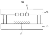
도 1을 참조하면, 예시적인 실시예들에 따른 기판 처리 장치(100)는 평판 디스플레이 소자로 제조하기 위한 기판(11) 상에 약액을 토출하는 인쇄 공정에 적용하기 위한 것으로써, 예를 들면 액정 디스플레이 소자로 제조하기 위한 기판(11) 상에 배향막을 형성하는 인쇄 공정에 적용할 수 있거나, 유기 EL 소자로 제조하기 위한 기판(11) 상에 컬러 필터를 형성하는 인쇄 공정에 적용할 수 있다.Referring to FIG. 1, the
예시적인 실시예들에 따른 기판 처리 장치(100)는 스테이지(13), 잉크젯 헤드 유닛(50), 갠트리(gantry)(15) 등을 포함할 수 있다.The
스테이지(13)는 기판(11)이 안착되는 부재로써, 기판(11)보다 큰 면적으로 이루어지는 직사각형의 플레이트 구조를 갖도록 구비될 수 있다. 스테이지(13)는 기판(11)이 안착되는 상태에서 회전할 수 있도록 구비될 수 있다. 이에, 스테이지(13)는 스테이지(13)를 회전시킬 수 있는 회전 구동 부재가 연결되도록 구비될 수 있다.The
갠트리(15)는 잉크젯 헤드 유닛(50)을 지지하도록 구비될 수 있다. 갠트리(15)는 잉크젯 헤드 유닛(50)이 스테이지(13) 상부에 배치되도록 구비될 수 있다.The
이에, 잉크젯 헤드 유닛(50)은 갠트리(15)에 의해 스테이지(13) 상부에 배치되어 기판(11) 상에 약액을 토출할 수 있다.Accordingly, the
이하, 예시적인 실시예들에 따른 기판 처리 장치에 구비되는 잉크젯 헤드 유닛에 대하여 설명하기로 한다.Hereinafter, an inkjet head unit provided in the substrate processing apparatus according to the exemplary embodiments will be described.
도 2 및 도 3은 예시적인 실시예들에 따른 기판 처리 장치에 구비되는 잉크젯 헤드 유닛을 사용하여 인쇄 공정을 수행하는 상황을 설명하기 위한 도면들이고, 도 4 및 도 5는 예시적인 실시예들에 따른 기판 처리 장치에 구비되는 잉크젯 헤드 유닛을 사용하지 않은 상황을 설명하기 위한 도면들이다.2 and 3 are diagrams for explaining a situation in which a printing process is performed using an inkjet head unit provided in a substrate processing apparatus according to example embodiments, and FIGS. 4 and 5 are exemplary embodiments It is a view for explaining the situation that the inkjet head unit provided in the substrate processing apparatus according to the present invention is not used.
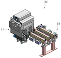
도 2 내지 도 5를 참조하면, 예시적인 실시예들에 따른 잉크젯 헤드 유닛(50)은 잉크젯 헤드(51), 경화부(53) 등을 포함할 수 있다.2 to 5, the
잉크젯 헤드(51)에는 약액을 토출하기 위한 복수개의 노즐이 구비될 수 있다. 예를 들면, 하나의 잉크젯 헤드(51)에는 128개 또는 256개의 노즐이 구비될 수 있다. 잉크젯 헤드(51)에 구비되는 노즐은 일정 간격을 갖도록 배치될 수 있다. 따라서 잉크젯 헤드(51)의 저면에는 128개 또는 256개의 노즐이 배치되는 노즐면이 형성될 수 있다.The
잉크젯 헤드 유닛(50)에는 복수개의 잉크젯 헤드(51)가 팩 단위로 배치될 수 있다. 예를 들면, 하나의 잉크젯 헤드 유닛(50)에는 세 개의 잉크젯 헤드(51)가 팩 단위로 배치될 수 있다.A plurality of
잉크젯 헤드(51)가 복수개로 구비될 경우 노즐면은 서로 이웃하게 배치되는 구조를 갖도록 형성될 수 있다. 언급한 바와 같이, 세 개의 잉크젯 헤드(51)가 팩 단위로 배치될 경우에는 노즐면 또한 세 개가 서로 이웃하게 배치되는 구조를 갖도록 형성될 수 있을 것이다.When a plurality of
경화부(53)는 기판 상에 토출되는 약액을 경화시키도록 구비될 수 있다. 경화부(53)는 자외선을 조사할 수 있는 자외선 램프로 이루어질 수 있다. 경화부(53)는 기판을 향하여 자외선을 조사할 수 있는 자외선 램프로 이루어질 수 있다.The curing
예시적인 실시예들에 따른 기판 처리 장치(100)에 구비되는 잉크젯 헤드 유닛(50)에서의 경화부(53)는 도 2 및 도 3에서와 같이 잉크젯 헤드(51)를 사용하여 약액을 토출하는 인쇄 공정의 수행 시에는 기판 상에 토출되는 약액을 경화시킬 수 있도록 잉크젯 헤드(51)의 노즐면 근방에 배치되게 구비될 수 있을 것이다.The curing
예시적인 실시예들에 따른 기판 처리 장치(100)에 구비되는 잉크젯 헤드 유닛(50)에서의 경화부(53)는 도 4 및 도 5에서와 같이 인쇄 공정을 수행하지 않을 시에는 잉크젯 헤드(51)의 노즐면으로부터 격리되도록 구비될 수 있을 것이다. 즉, 인쇄 공정을 수행한 후 잉크젯 헤드 유닛(50)을 유지 보수하거나 또는 인쇄 공정의 수행을 위한 대기 모드 시에는 경화부(53)를 잉크젯 헤드(51)의 노즐면으로부터 격리되도록 구비시킬 수 있는 것이다.The hardening
이에, 경화부(53)는 경화부(53)를 잉크젯 헤드(51)의 노즐면 근방에 배치되도록 이동시키거나 또는 경화부(53)를 잉크젯 헤드(51)의 노즐면으로부터 격리되도록 이동시킬 수 있는 이동 부재와 연결되는 구조를 갖도록 구비될 수 있을 것이다.Accordingly, the curing
언급한 바와 같이, 잉크젯 헤드(51)가 복수개로 구비됨에 따라 노즐면도 복수개가 서로 이웃하게 배치되는 구조를 가질 경우 경화부(53)는 노즐면 사이에 배치되도록 구비될 수 있다. 즉, 잉크젯 헤드(51)의 노즐면과 경화부(53)는 서로 맞물리게 대응되는 포크 구조를 갖도록 구비될 수 있는 것이다.As mentioned, when the
이에, 예시적인 실시예들에 따른 잉크젯 헤드 유닛(50)을 구비하는 기판 처리 장치(100)를 사용하는 인쇄 공정의 수행시에는 경화부(53)를 사용하여 기판 상에 토출되는 약액을 경화시킬 수 있고, 인쇄 공정을 수행하지 않을 경우에는 잉크젯 헤드(50)의 노즐면으로부터 경화부(53)를 격리시킬 수 있을 것이다.Thus, when performing the printing process using the
따라서 예시적인 실시예들에 따른 잉크젯 헤드 유닛(50) 및 기판 처리 장치(100)는 인쇄 공정을 수행하지 않을 경우 잉크젯 헤드(51)로부터 경화부(53)를 격리시킬 수 있기 때문에 경화부(53)로 인하여 잉크젯 헤드(51)의 노즐이 배치되는 노즐면에 잔류하는 약액이 경화되는 상황을 사전에 차단할 수 있을 것이고, 그 결과 노즐면에 잔류하는 약액이 경화됨에 의해 노즐이 막히는 상황을 방지할 수 있을 것이다.Therefore, the
예시적인 실시예들에 따른 잉크젯 헤드 유닛 및 기판 처리 장치는 기판 상에 약액을 도포하는 공정에 적용할 수 있기에, 액정 표시 소자, 유기 EL 소자 등과 같은 표시 장치의 제조에 보다 적극적으로 적용할 수 있을 것이다.Since the inkjet head unit and the substrate processing apparatus according to the exemplary embodiments can be applied to a process of applying a chemical liquid on a substrate, it can be more actively applied to the manufacture of display devices such as liquid crystal display elements, organic EL elements, and the like. will be.
상기에서는 본 발명의 바람직한 실시예를 참조하여 설명하였지만, 해당 기술 분야의 숙련된 당업자는 하기의 특허 청구 범위에 기재된 본 발명의 사상 및 영역으로부터 벗어나지 않는 범위 내에서 본 발명을 다양하게 수정 및 변경시킬 수 있음을 이해할 수 있을 것이다.Although described above with reference to the preferred embodiments of the present invention, those skilled in the art may variously modify and change the present invention without departing from the spirit and scope of the present invention as set forth in the claims below. You will understand that you can.
11 : 기판 13 : 스테이지
15 : 갠트리 50 : 잉크젯 헤드 유닛
51 : 잉크젯 헤드 53 : 경화부
100 : 기판 처리 장치11: Substrate 13: Stage
15: gantry 50: inkjet head unit
51: inkjet head 53: hardened portion
100: substrate processing apparatus
Claims (7)
상기 잉크젯 헤드를 사용하여 상기 약액을 토출하는 인쇄 공정의 수행 시에는 상기 기판 상에 토출되는 상기 약액을 경화시킬 수 있도록 상기 잉크젯 헤드의 노즐이 배치되는 노즐면 근방에 구비되고, 상기 인쇄 공정을 수행하지 않을 시에는 상기 잉크젯 헤드의 노즐면으로부터 격리되도록 구비되는 경화부를 포함하는 것을 특징으로 하는 잉크젯 헤드 유닛.An inkjet head provided with a nozzle for discharging the chemical liquid on the substrate; And
When performing the printing process of discharging the chemical liquid using the inkjet head, it is provided near the nozzle surface where the nozzle of the inkjet head is disposed so as to cure the chemical liquid discharged on the substrate, and performs the printing process When not, the inkjet head unit, characterized in that it comprises a curing portion provided to be isolated from the nozzle surface of the inkjet head.
상기 노즐면이 서로 이웃하게 배치되는 구조를 갖도록 상기 잉크젯 헤드가 복수개로 구비될 때, 상기 경화부는 상기 노즐면 사이에 배치되도록 구비되는 것을 특징으로 하는 잉크젯 헤드 유닛.According to claim 1,
The inkjet head unit, characterized in that when the plurality of inkjet heads are provided so that the nozzle faces are arranged adjacent to each other, the curing part is disposed between the nozzle faces.
상기 경화부는 상기 기판을 향하여 자외선을 조사할 수 있는 자외선 램프로 이루어지는 것을 특징으로 하는 잉크젯 헤드 유닛.According to claim 1,
The curing unit is an inkjet head unit, characterized in that consisting of an ultraviolet lamp capable of irradiating ultraviolet light toward the substrate.
상기 기판 상에 약액을 토출하도록 구비되는 잉크젯 헤드 유닛를 포함하고,
상기 잉크젯 헤드 유닛은 상기 기판 상에 약액을 토출하기 위한 노즐이 구비되는 잉크젯 헤드, 및 상기 잉크젯 헤드를 사용하여 상기 약액을 토출하는 인쇄 공정의 수행 시에는 상기 기판 상에 토출되는 상기 약액을 경화시킬 수 있도록 상기 잉크젯 헤드의 노즐이 배치되는 노즐면 근방에 구비되고, 상기 인쇄 공정을 수행하지 않을 시에는 상기 잉크젯 헤드의 노즐면으로부터 격리되도록 구비되는 경화부를 포함하는 것을 특징으로 하는 기판 처리 장치.A stage on which the substrate is seated; And
It includes an inkjet head unit provided to discharge the chemical liquid on the substrate,
The inkjet head unit may harden the chemical liquid discharged on the substrate when performing an inkjet head provided with a nozzle for discharging the chemical liquid on the substrate, and a printing process for discharging the chemical liquid using the inkjet head. A substrate processing apparatus comprising a hardened portion provided near the nozzle surface where the nozzle of the inkjet head is arranged so as to be isolated from the nozzle surface of the inkjet head when the printing process is not performed.
상기 노즐면이 서로 이웃하게 배치되는 구조를 갖도록 상기 잉크젯 헤드가 복수개로 구비될 때, 상기 경화부는 상기 노즐면 사이에 배치되도록 구비되는 것을 특징으로 하는 기판 처리 장치.According to claim 4,
When the plurality of inkjet heads are provided so that the nozzle faces are arranged adjacent to each other, the curing unit is provided to be disposed between the nozzle faces.
상기 경화부는 상기 기판을 향하여 자외선을 조사할 수 있는 자외선 램프로 이루어지는 것을 특징으로 하는 기판 처리 장치.According to claim 4,
The curing unit is a substrate processing apparatus, characterized in that consisting of an ultraviolet lamp capable of irradiating ultraviolet light toward the substrate.
상기 잉크젯 헤드 유닛이 상기 스테이지 상부에 배치되게 상기 잉크젯 헤드 유닛을 지지하도록 구비되는 갠트리를 더 포함하는 것을 특징으로 하는 기판 처리 장치.According to claim 4,
And a gantry provided to support the inkjet head unit such that the inkjet head unit is disposed on the stage.
Priority Applications (1)
| Application Number | Priority Date | Filing Date | Title |
|---|---|---|---|
| KR1020180125680A KR20200045099A (en) | 2018-10-22 | 2018-10-22 | Inkjet Head Unit and Apparatus for Processing Substrate having the same |
Applications Claiming Priority (1)
| Application Number | Priority Date | Filing Date | Title |
|---|---|---|---|
| KR1020180125680A KR20200045099A (en) | 2018-10-22 | 2018-10-22 | Inkjet Head Unit and Apparatus for Processing Substrate having the same |
Publications (1)
| Publication Number | Publication Date |
|---|---|
| KR20200045099A true KR20200045099A (en) | 2020-05-04 |
Family
ID=70732731
Family Applications (1)
| Application Number | Title | Priority Date | Filing Date |
|---|---|---|---|
| KR1020180125680A KR20200045099A (en) | 2018-10-22 | 2018-10-22 | Inkjet Head Unit and Apparatus for Processing Substrate having the same |
Country Status (1)
| Country | Link |
|---|---|
| KR (1) | KR20200045099A (en) |
-
2018
- 2018-10-22 KR KR1020180125680A patent/KR20200045099A/en not_active Application Discontinuation
Similar Documents
| Publication | Publication Date | Title |
|---|---|---|
| KR100691710B1 (en) | Color filter and method for manufacturing the same, electro-optical device, and electronic apparatus | |
| KR102440568B1 (en) | Aligning method of droplet apparatus | |
| JP2007029946A (en) | Droplet discharge method, electro-optical device and electronic device | |
| KR102142750B1 (en) | Method for bonding substrate and substrate for display manufactured by the same | |
| TWI376982B (en) | Coating method and pattern forming method | |
| KR20200045099A (en) | Inkjet Head Unit and Apparatus for Processing Substrate having the same | |
| KR20090127694A (en) | Pattern forming apparatus of flat panel display and pattern forming method using it | |
| KR102440567B1 (en) | Apparatus and Method for treating a substrate | |
| JP6274832B2 (en) | Thin film forming method and thin film forming apparatus | |
| KR102532509B1 (en) | Inkjet printer for manufacturing dislpay | |
| TW200827879A (en) | Method for disposing spacer | |
| KR20200048349A (en) | Apparatus for Printing and Method for Printing | |
| KR101912606B1 (en) | Nozzle Plate for Processing Droplet Formation and Coating Method of Nozzle Plate for Processing Droplet Formation | |
| KR102347409B1 (en) | Inkjet Printer | |
| JP5261976B2 (en) | Spacer forming method and blanket base material used therefor | |
| KR102559882B1 (en) | Method and Apparatus for Droplet Formation | |
| KR102294345B1 (en) | Method for Coating Optically Clear Adhesive | |
| KR100811330B1 (en) | Method of manufacturing color filter layer and apparatus for the same | |
| JP4023287B2 (en) | Manufacturing method of liquid crystal display device | |
| JP5167890B2 (en) | Manufacturing method of color filter substrate with spacer | |
| KR102178802B1 (en) | Ink-jet head unit and coating method thereof | |
| KR20240041386A (en) | Coating method and coating apparatus | |
| JP5640321B2 (en) | Method for forming arrangement of microsphere and spacer forming method for color filter for flat panel display using the same | |
| KR102625205B1 (en) | Apparatus for Droplet Formation | |
| KR20200055258A (en) | Method for Forming Thin Film Replacing Tape |
Legal Events
| Date | Code | Title | Description |
|---|---|---|---|
| E902 | Notification of reason for refusal | ||
| E601 | Decision to refuse application |