KR20200044577A - Large module of battery - Google Patents
Large module of battery Download PDFInfo
- Publication number
- KR20200044577A KR20200044577A KR1020180125548A KR20180125548A KR20200044577A KR 20200044577 A KR20200044577 A KR 20200044577A KR 1020180125548 A KR1020180125548 A KR 1020180125548A KR 20180125548 A KR20180125548 A KR 20180125548A KR 20200044577 A KR20200044577 A KR 20200044577A
- Authority
- KR
- South Korea
- Prior art keywords
- wall
- cell stack
- module housing
- module
- cell
- Prior art date
Links
- 238000003780 insertion Methods 0.000 claims abstract description 54
- 230000037431 insertion Effects 0.000 claims abstract description 54
- 238000010168 coupling process Methods 0.000 claims abstract description 24
- 230000008878 coupling Effects 0.000 claims abstract description 23
- 238000005859 coupling reaction Methods 0.000 claims abstract description 23
- 238000001816 cooling Methods 0.000 claims description 34
- 230000035939 shock Effects 0.000 claims description 26
- 238000000926 separation method Methods 0.000 claims description 21
- 230000008961 swelling Effects 0.000 claims description 18
- 238000010521 absorption reaction Methods 0.000 claims description 13
- 239000000498 cooling water Substances 0.000 claims description 13
- 238000000034 method Methods 0.000 claims description 12
- 238000007789 sealing Methods 0.000 claims description 10
- 238000004891 communication Methods 0.000 claims description 8
- 238000004519 manufacturing process Methods 0.000 abstract description 8
- 238000005266 casting Methods 0.000 description 8
- 238000003825 pressing Methods 0.000 description 6
- 230000008859 change Effects 0.000 description 3
- 239000002184 metal Substances 0.000 description 3
- 230000008569 process Effects 0.000 description 3
- 230000004308 accommodation Effects 0.000 description 2
- 238000006243 chemical reaction Methods 0.000 description 2
- 238000011161 development Methods 0.000 description 2
- 238000007599 discharging Methods 0.000 description 2
- 239000003792 electrolyte Substances 0.000 description 2
- 239000011810 insulating material Substances 0.000 description 2
- 239000000463 material Substances 0.000 description 2
- 239000004033 plastic Substances 0.000 description 2
- 241000282472 Canis lupus familiaris Species 0.000 description 1
- 230000005540 biological transmission Effects 0.000 description 1
- 239000004020 conductor Substances 0.000 description 1
- 238000009792 diffusion process Methods 0.000 description 1
- 238000003487 electrochemical reaction Methods 0.000 description 1
- 238000005516 engineering process Methods 0.000 description 1
- 238000010438 heat treatment Methods 0.000 description 1
- 230000006872 improvement Effects 0.000 description 1
- 230000002427 irreversible effect Effects 0.000 description 1
- 238000012423 maintenance Methods 0.000 description 1
- 239000007769 metal material Substances 0.000 description 1
- 238000005192 partition Methods 0.000 description 1
- 229920000642 polymer Polymers 0.000 description 1
- 239000003507 refrigerant Substances 0.000 description 1
- 239000000126 substance Substances 0.000 description 1
- 238000003466 welding Methods 0.000 description 1
Images


Classifications
-
- H01M2/1077—
-
- H—ELECTRICITY
- H01—ELECTRIC ELEMENTS
- H01M—PROCESSES OR MEANS, e.g. BATTERIES, FOR THE DIRECT CONVERSION OF CHEMICAL ENERGY INTO ELECTRICAL ENERGY
- H01M10/00—Secondary cells; Manufacture thereof
- H01M10/60—Heating or cooling; Temperature control
- H01M10/65—Means for temperature control structurally associated with the cells
- H01M10/656—Means for temperature control structurally associated with the cells characterised by the type of heat-exchange fluid
- H01M10/6567—Liquids
- H01M10/6568—Liquids characterised by flow circuits, e.g. loops, located externally to the cells or cell casings
-
- H—ELECTRICITY
- H01—ELECTRIC ELEMENTS
- H01M—PROCESSES OR MEANS, e.g. BATTERIES, FOR THE DIRECT CONVERSION OF CHEMICAL ENERGY INTO ELECTRICAL ENERGY
- H01M50/00—Constructional details or processes of manufacture of the non-active parts of electrochemical cells other than fuel cells, e.g. hybrid cells
- H01M50/20—Mountings; Secondary casings or frames; Racks, modules or packs; Suspension devices; Shock absorbers; Transport or carrying devices; Holders
-
- H—ELECTRICITY
- H01—ELECTRIC ELEMENTS
- H01M—PROCESSES OR MEANS, e.g. BATTERIES, FOR THE DIRECT CONVERSION OF CHEMICAL ENERGY INTO ELECTRICAL ENERGY
- H01M10/00—Secondary cells; Manufacture thereof
- H01M10/42—Methods or arrangements for servicing or maintenance of secondary cells or secondary half-cells
- H01M10/425—Structural combination with electronic components, e.g. electronic circuits integrated to the outside of the casing
-
- H—ELECTRICITY
- H01—ELECTRIC ELEMENTS
- H01M—PROCESSES OR MEANS, e.g. BATTERIES, FOR THE DIRECT CONVERSION OF CHEMICAL ENERGY INTO ELECTRICAL ENERGY
- H01M10/00—Secondary cells; Manufacture thereof
- H01M10/60—Heating or cooling; Temperature control
- H01M10/61—Types of temperature control
- H01M10/613—Cooling or keeping cold
-
- H—ELECTRICITY
- H01—ELECTRIC ELEMENTS
- H01M—PROCESSES OR MEANS, e.g. BATTERIES, FOR THE DIRECT CONVERSION OF CHEMICAL ENERGY INTO ELECTRICAL ENERGY
- H01M10/00—Secondary cells; Manufacture thereof
- H01M10/60—Heating or cooling; Temperature control
- H01M10/62—Heating or cooling; Temperature control specially adapted for specific applications
- H01M10/625—Vehicles
-
- H—ELECTRICITY
- H01—ELECTRIC ELEMENTS
- H01M—PROCESSES OR MEANS, e.g. BATTERIES, FOR THE DIRECT CONVERSION OF CHEMICAL ENERGY INTO ELECTRICAL ENERGY
- H01M10/00—Secondary cells; Manufacture thereof
- H01M10/60—Heating or cooling; Temperature control
- H01M10/65—Means for temperature control structurally associated with the cells
- H01M10/655—Solid structures for heat exchange or heat conduction
- H01M10/6556—Solid parts with flow channel passages or pipes for heat exchange
-
- H—ELECTRICITY
- H01—ELECTRIC ELEMENTS
- H01M—PROCESSES OR MEANS, e.g. BATTERIES, FOR THE DIRECT CONVERSION OF CHEMICAL ENERGY INTO ELECTRICAL ENERGY
- H01M10/00—Secondary cells; Manufacture thereof
- H01M10/60—Heating or cooling; Temperature control
- H01M10/65—Means for temperature control structurally associated with the cells
- H01M10/656—Means for temperature control structurally associated with the cells characterised by the type of heat-exchange fluid
- H01M10/6567—Liquids
-
- H01M2/206—
-
- H—ELECTRICITY
- H01—ELECTRIC ELEMENTS
- H01M—PROCESSES OR MEANS, e.g. BATTERIES, FOR THE DIRECT CONVERSION OF CHEMICAL ENERGY INTO ELECTRICAL ENERGY
- H01M50/00—Constructional details or processes of manufacture of the non-active parts of electrochemical cells other than fuel cells, e.g. hybrid cells
- H01M50/20—Mountings; Secondary casings or frames; Racks, modules or packs; Suspension devices; Shock absorbers; Transport or carrying devices; Holders
- H01M50/204—Racks, modules or packs for multiple batteries or multiple cells
- H01M50/207—Racks, modules or packs for multiple batteries or multiple cells characterised by their shape
- H01M50/209—Racks, modules or packs for multiple batteries or multiple cells characterised by their shape adapted for prismatic or rectangular cells
-
- H—ELECTRICITY
- H01—ELECTRIC ELEMENTS
- H01M—PROCESSES OR MEANS, e.g. BATTERIES, FOR THE DIRECT CONVERSION OF CHEMICAL ENERGY INTO ELECTRICAL ENERGY
- H01M50/00—Constructional details or processes of manufacture of the non-active parts of electrochemical cells other than fuel cells, e.g. hybrid cells
- H01M50/20—Mountings; Secondary casings or frames; Racks, modules or packs; Suspension devices; Shock absorbers; Transport or carrying devices; Holders
- H01M50/262—Mountings; Secondary casings or frames; Racks, modules or packs; Suspension devices; Shock absorbers; Transport or carrying devices; Holders with fastening means, e.g. locks
-
- H—ELECTRICITY
- H01—ELECTRIC ELEMENTS
- H01M—PROCESSES OR MEANS, e.g. BATTERIES, FOR THE DIRECT CONVERSION OF CHEMICAL ENERGY INTO ELECTRICAL ENERGY
- H01M50/00—Constructional details or processes of manufacture of the non-active parts of electrochemical cells other than fuel cells, e.g. hybrid cells
- H01M50/50—Current conducting connections for cells or batteries
- H01M50/502—Interconnectors for connecting terminals of adjacent batteries; Interconnectors for connecting cells outside a battery casing
- H01M50/503—Interconnectors for connecting terminals of adjacent batteries; Interconnectors for connecting cells outside a battery casing characterised by the shape of the interconnectors
-
- H—ELECTRICITY
- H01—ELECTRIC ELEMENTS
- H01M—PROCESSES OR MEANS, e.g. BATTERIES, FOR THE DIRECT CONVERSION OF CHEMICAL ENERGY INTO ELECTRICAL ENERGY
- H01M50/00—Constructional details or processes of manufacture of the non-active parts of electrochemical cells other than fuel cells, e.g. hybrid cells
- H01M50/50—Current conducting connections for cells or batteries
- H01M50/502—Interconnectors for connecting terminals of adjacent batteries; Interconnectors for connecting cells outside a battery casing
- H01M50/505—Interconnectors for connecting terminals of adjacent batteries; Interconnectors for connecting cells outside a battery casing comprising a single busbar
-
- H—ELECTRICITY
- H01—ELECTRIC ELEMENTS
- H01M—PROCESSES OR MEANS, e.g. BATTERIES, FOR THE DIRECT CONVERSION OF CHEMICAL ENERGY INTO ELECTRICAL ENERGY
- H01M10/00—Secondary cells; Manufacture thereof
- H01M10/42—Methods or arrangements for servicing or maintenance of secondary cells or secondary half-cells
- H01M10/425—Structural combination with electronic components, e.g. electronic circuits integrated to the outside of the casing
- H01M2010/4271—Battery management systems including electronic circuits, e.g. control of current or voltage to keep battery in healthy state, cell balancing
-
- H—ELECTRICITY
- H01—ELECTRIC ELEMENTS
- H01M—PROCESSES OR MEANS, e.g. BATTERIES, FOR THE DIRECT CONVERSION OF CHEMICAL ENERGY INTO ELECTRICAL ENERGY
- H01M2220/00—Batteries for particular applications
- H01M2220/20—Batteries in motive systems, e.g. vehicle, ship, plane
-
- H—ELECTRICITY
- H01—ELECTRIC ELEMENTS
- H01M—PROCESSES OR MEANS, e.g. BATTERIES, FOR THE DIRECT CONVERSION OF CHEMICAL ENERGY INTO ELECTRICAL ENERGY
- H01M50/00—Constructional details or processes of manufacture of the non-active parts of electrochemical cells other than fuel cells, e.g. hybrid cells
- H01M50/20—Mountings; Secondary casings or frames; Racks, modules or packs; Suspension devices; Shock absorbers; Transport or carrying devices; Holders
- H01M50/233—Mountings; Secondary casings or frames; Racks, modules or packs; Suspension devices; Shock absorbers; Transport or carrying devices; Holders characterised by physical properties of casings or racks, e.g. dimensions
- H01M50/242—Mountings; Secondary casings or frames; Racks, modules or packs; Suspension devices; Shock absorbers; Transport or carrying devices; Holders characterised by physical properties of casings or racks, e.g. dimensions adapted for protecting batteries against vibrations, collision impact or swelling
-
- H—ELECTRICITY
- H01—ELECTRIC ELEMENTS
- H01M—PROCESSES OR MEANS, e.g. BATTERIES, FOR THE DIRECT CONVERSION OF CHEMICAL ENERGY INTO ELECTRICAL ENERGY
- H01M50/00—Constructional details or processes of manufacture of the non-active parts of electrochemical cells other than fuel cells, e.g. hybrid cells
- H01M50/20—Mountings; Secondary casings or frames; Racks, modules or packs; Suspension devices; Shock absorbers; Transport or carrying devices; Holders
- H01M50/289—Mountings; Secondary casings or frames; Racks, modules or packs; Suspension devices; Shock absorbers; Transport or carrying devices; Holders characterised by spacing elements or positioning means within frames, racks or packs
-
- Y—GENERAL TAGGING OF NEW TECHNOLOGICAL DEVELOPMENTS; GENERAL TAGGING OF CROSS-SECTIONAL TECHNOLOGIES SPANNING OVER SEVERAL SECTIONS OF THE IPC; TECHNICAL SUBJECTS COVERED BY FORMER USPC CROSS-REFERENCE ART COLLECTIONS [XRACs] AND DIGESTS
- Y02—TECHNOLOGIES OR APPLICATIONS FOR MITIGATION OR ADAPTATION AGAINST CLIMATE CHANGE
- Y02E—REDUCTION OF GREENHOUSE GAS [GHG] EMISSIONS, RELATED TO ENERGY GENERATION, TRANSMISSION OR DISTRIBUTION
- Y02E60/00—Enabling technologies; Technologies with a potential or indirect contribution to GHG emissions mitigation
- Y02E60/10—Energy storage using batteries
Abstract
Description
본 발명은 배터리의 대형 모듈에 관한 것으로서, 복수의 단위셀로 이루어지는 셀스택을 복수개 포함하는 배터리의 대형 모듈에 관한 것이다.The present invention relates to a large module of a battery, and relates to a large module of a battery including a plurality of cell stacks composed of a plurality of unit cells.
충전식 또는 이차전지는 충전 및 방전이 반복될 수 있다는 점에서 1차전지와 다르며, 후자는 화학물질에서 전기에너지로의 비가역적 변환만을 제공한다. 저용량의 충전식 전지는 휴대 전화, 노트북, 컴퓨터 및 캠코더와 같은 소형 전자장치의 전원으로 사용되고, 대용량의 충전식 전지는 하이브리드 자동차 등의 전원으로 사용될 수 있다.Rechargeable or secondary batteries differ from primary batteries in that charging and discharging can be repeated, the latter providing only irreversible conversion of chemicals to electrical energy. The low-capacity rechargeable battery can be used as a power source for small electronic devices such as mobile phones, laptops, computers, and camcorders, and the large-capacity rechargeable battery can be used as a power source for hybrid vehicles and the like.
이차전지는 양극, 음극 및 상기 양극과 음극 사이에 개재된 세퍼레이터를 포함하는 전극조립체, 상기 전극조립체를 수용하는 케이스 및 상기 전극 조립체와 전기적으로 연결되는 전극단자를 포함할 수 있다.The secondary battery may include an electrode assembly including an anode, a cathode, and a separator interposed between the anode and the cathode, a case accommodating the electrode assembly, and an electrode terminal electrically connected to the electrode assembly.
전해액은 양극, 음극 및 상기 전해액의 전기 화학적 반응으로 전지, 즉 배터리의 충방전이 가능하도록 하기 위해 케이스 내부로 주입된다. 예컨대 원통형 또는 직사각형일 수 있는 케이스의 형상은 전지의 용도에 따라 다를 수 있다.The electrolyte is injected into the case to enable charging and discharging of the battery, that is, the battery by electrochemical reaction of the positive electrode, the negative electrode, and the electrolyte. For example, the shape of the case, which may be cylindrical or rectangular, may vary depending on the application of the battery.
충전식 전지는 직렬 또는 병렬로 결합된 다수의 단위셀로 구성되는 셀스택 형태로 사용됨으로써, 예컨대 하이브리드 자동차의 주행 등을 위한 높은 에너지밀도를 제공할 수 있다.The rechargeable battery is used in the form of a cell stack composed of a plurality of unit cells coupled in series or in parallel, thereby providing a high energy density for driving a hybrid vehicle, for example.
상기 셀스택은 엔드블록 및 사이드플레이트 등으로 구성되는 모듈프레임을 통해 하나의 단위 구성으로 조립 및 취급될 수 있으며, 배터리 모듈은 하우징 내부에 모듈프레임이 체결된 셀스택이 삽입되고 하우징과 상기 모듈프레임이 결합된 형태를 가질 수 있다.The cell stack can be assembled and handled as a single unit through a module frame composed of an end block and a side plate, and the battery module is inserted into a cell stack in which a module frame is fastened inside the housing and the housing and the module frame It can have a combined form.
한편, 기술의 발전에 따라 전기자동차(EV), 하이브리드 자동차(HEV) 및 기타 전기에너지 소비장치에서 요구되는 전력량이 증가되고 있으며, 상기 전력량을 만족시키기 위해 복수의 배터리 모듈이 제공될 수 있다.Meanwhile, with the development of technology, the amount of power required in electric vehicles (EV), hybrid vehicles (HEV) and other electric energy consuming devices is increasing, and a plurality of battery modules may be provided to satisfy the amount of power.
다만, 배터리 모듈의 구성품인 셀스택은 단위 구성으로의 취급 용이성 및 정렬방향으로의 가압상태 유지를 위해 엔드블록 및 사이드플레이트 등을 이용한 체결구조를 가지며, 이러한 추가 구성을 포함하는 배터리 모듈의 요구수량이 증가될수록 배터리 모듈의 제조 공정 및 제조단가가 증가할 수 있다.However, the cell stack, which is a component of the battery module, has a fastening structure using an end block and a side plate for ease of handling in a unit configuration and maintaining a pressurized state in the alignment direction, and the required quantity of the battery module including such an additional configuration As this increases, the manufacturing process and manufacturing cost of the battery module may increase.
따라서, 전기에너지 소비장치의 요구전력을 충족시킬 수 있는 복수의 셀스택을 제공하면서 구성부품을 단순화하고 제조단가 및 중량을 효과적으로 감소시키며 제조 공정이 효율적으로 진행될 수 있는 새로운 모듈 구조의 개발은 중요한 과제가 된다.Therefore, the development of a new module structure that simplifies components, effectively reduces manufacturing cost and weight, and enables the manufacturing process to proceed efficiently while providing a plurality of cell stacks capable of meeting the required power of the electric energy consuming device is an important task. Becomes
본 발명의 실시예들은 전력량을 효과적으로 향상시키고, 구성부품을 단순화하면서 제조 공정을 효율적으로 개선할 수 있는 배터리의 대형 모듈을 제공하고자 한다.Embodiments of the present invention is to provide a large module of a battery that can effectively improve the amount of power, simplify the components and improve the manufacturing process efficiently.
본 발명의 일실시예에 따른 배터리의 대형 모듈은 복수의 단위셀이 제1방향으로 정렬되고, 상기 복수의 단위셀을 둘러싸는 절연부재를 포함하는 셀스택 및 상기 셀스택이 삽입되는 삽입부가 복수개로 마련되는 모듈하우징을 포함하며, 상기 삽입부는, 상기 셀스택을 둘러싸며 적어도 일부가 상기 셀스택과 접촉되는 고정벽을 포함하고, 상기 모듈하우징에 구비되고, 이웃하는 모듈하우징과 결합되는 결합부를 더 포함하며, 상기 결합부는, 상기 모듈하우징 및 상기 이웃하는 모듈하우징을 전기적 및 신호적으로 연결하는 커넥터를 포함한다.In a large module of a battery according to an embodiment of the present invention, a plurality of cell stacks in which a plurality of unit cells are aligned in a first direction, and an insulating member surrounding the plurality of unit cells, and a plurality of inserts into which the cell stack is inserted are inserted. It includes a module housing is provided, wherein the insertion portion, and includes a fixed wall surrounding at least a portion of the cell stack in contact with the cell stack, provided in the module housing, coupled to the adjacent module housing coupled Further included, the coupling portion includes a connector for electrically and signally connecting the module housing and the neighboring module housing.
상기 커넥터는, 상기 모듈하우징의 내부공간을 둘러싸는 외벽 중 상기 제1방향에 수직한 제2방향에 위치되는 제1벽에 구비되는 숫커넥터 및 상기 외벽 중 상기 제1벽의 반대측에 위치되는 제2벽에 구비되어 상기 이웃하는 모듈하우징의 숫커넥터와 결합되는 암커넥터를 포함할 수 있다.The connector includes a male connector provided on a first wall located in a second direction perpendicular to the first direction among outer walls surrounding the inner space of the module housing, and a first connector located on the opposite side of the first wall among the outer walls. It may be provided on the second wall may include a female connector coupled to the male connector of the adjacent module housing.
상기 숫커넥터는, 상기 제2방향으로 돌출되고 상기 모듈하우징 내부에서 셀스택과 전기적으로 연결되는 전류연결부를 포함하고, 상기 암커넥터는 상기 제2방향으로 만입되고 상기 이웃하는 모듈하우징의 상기 숫커넥터의 상기 전류연결부가 삽입되는 전류수용부를 포함할 수 있다.The male connector includes a current connector protruding in the second direction and electrically connected to a cell stack inside the module housing, wherein the female connector is indented in the second direction and the male connector of the neighboring module housing It may include a current receiving portion of the current connection is inserted.
상기 숫커넥터는, 상기 제2방향으로 돌출되고 상기 셀스택의 관리제어신호를 전달하는 신호연결부를 더 포함하고, 상기 암커넥터는, 상기 제2방향으로 만입되고 상기 이웃하는 모듈하우징의 상기 숫커넥터의 상기 신호연결부가 삽입되는 신호수용부를 더 포함할 수 있다.The male connector further includes a signal connector protruding in the second direction and transmitting a management control signal of the cell stack, and the female connector is indented in the second direction and the male connector of the neighboring module housing. The signal connecting portion of the may further include a signal receiving portion.
상기 커넥터는 중앙에 상기 모듈하우징의 내부와 외부가 연통되는 연통홀이 형성될 수 있다.In the connector, a communication hole in which the inside and the outside of the module housing communicate with each other may be formed in the center.
상기 결합부는, 상기 제1벽에서 상기 숫커넥터의 측부에 위치되며, 상기 제2방향으로 돌출되는 가이드돌기 및 상기 제2벽에서 상기 암커넥터의 측부에 위치되며, 상기 이웃하는 모듈하우징의 가이드돌기가 삽입되는 가이드홈을 더 포함할 수 있다.The coupling portion is located on the side of the male connector in the first wall, the guide projection protruding in the second direction and the side of the female connector in the second wall, the guide projection of the neighboring module housing It may further include a guide groove is inserted.
상기 가이드돌기에는 상기 외벽의 높이방향으로 체결홈이 형성되고, 상기 가이드홈의 측면에는 상기 체결홈과 대응되는 위치에 체결공이 형성되며, 상기 가이드돌기는 상기 체결공을 관통하여 상기 체결홈에 삽입되는 체결부재를 통해 상기 가이드홈과 결합될 수 있다.A fastening groove is formed in the guide projection in the height direction of the outer wall, a fastening hole is formed at a position corresponding to the fastening groove on a side of the guide groove, and the guide protrusion penetrates the fastening hole and is inserted into the fastening groove It can be coupled to the guide groove through the fastening member.
상기 숫커넥터는, 상기 전류연결부 및 상기 신호연결부를 둘러싸고, 상기 제2방향으로 돌출되며, 단부에 실러가 구비되는 실링벽을 더 포함할 수 있다.The male connector may further include a sealing wall surrounding the current connection part and the signal connection part, protruding in the second direction, and having a sealer at an end.
상기 삽입부는 상기 제2방향을 따라 제1열 및 제2열을 이루도록 배치되고, 상기 제1열에 포함되는 셀스택들은 상기 제2열에 포함되는 셀스택들과 서로 전기적으로 분리될 수 있다.The insertion portion is disposed to form a first column and a second column along the second direction, and the cell stacks included in the first column may be electrically separated from the cell stacks included in the second column.
상기 셀스택에서 상기 복수의 단위셀을 전기적으로 연결하는 스택버스바, 상기 제1열 또는 상기 제2열에서 상기 제2방향으로 이웃하는 2개의 셀스택을 전기적으로 연결하는 연결버스바 및 상기 셀스택으로부터 인출되며, 상기 전류연결부 또는 상기 전류수용부와 연결되는 단자버스바를 더 포함할 수 있다.A stack bus bar for electrically connecting the plurality of unit cells in the cell stack, a connection bus bar for electrically connecting two cell stacks neighboring in the second direction in the first column or the second column, and the cell A terminal bus bar that is withdrawn from the stack and is connected to the current connecting portion or the current receiving portion may be further included.
상기 전류연결부는, 상기 제1열에 포함되는 셀스택들과 전기적으로 연결되는 제1돌기; 및 상기 제2열에 포함되는 셀스택들과 전기적으로 연결되는 제2돌기를 포함하고, 상기 전류수용부는, 상기 제1열에 포함되는 셀스택들과 전기적으로 연결되며 상기 이웃하는 모듈하우징의 상기 제1돌기와 결합되는 제1수용부 및 상기 제2열에 포함되는 셀스택들과 전기적으로 연결되며 상기 이웃하는 모듈하우징의 상기 제2돌기와 결합되는 제2수용부을 포함할 수 있다.The current connection unit includes: a first protrusion electrically connected to cell stacks included in the first row; And a second protrusion electrically connected to the cell stacks included in the second row, wherein the current receiving unit is electrically connected to the cell stacks included in the first row and the first of the neighboring module housings. It may include a first accommodating portion coupled to the projection and a second accommodating portion electrically connected to the cell stacks included in the second row and coupled to the second projection of the neighboring module housing.
상기 셀스택에서 일단부의 단위셀에는 상기 단자버스바가 연결되고, 타단부의 단위셀에는 상기 연결버스바가 연결되며, 상기 셀스택은 상기 일단부가 상기 제1열 및 상기 제2열 사이를 바라보도록 배치되어, 상기 단자버스바가 상기 제1열 및 상기 제2열 사이로 인출될 수 있다.In the cell stack, the terminal bus bar is connected to one unit cell of the one end, and the connection bus bar is connected to the unit cell of the other end, and the cell stack is arranged such that one end of the cell stack faces the first column and the second column. Thus, the terminal bus bar may be withdrawn between the first row and the second row.
상기 제1열의 셀스택들로부터 인출되는 단자버스바들과 상기 제2열의 셀스택들로부터 인출되는 단자버스바들은 상기 제2방향을 따라 서로 교번하여 배치될 수 있다.The terminal bus bars drawn out from the cell stacks in the first row and the terminal bus bars drawn out from the cell stacks in the second row may be alternately arranged along the second direction.
상기 고정벽은, 상기 모듈하우징의 외벽으로 둘러싸인 내부공간을 상기 제1방향으로 가로지르며, 상기 셀스택의 사이드면에 접촉되는 분리벽 및 상기 제1방향 양측에 배치되어 상기 셀스택의 상기 제1방향 양측의 엔드면을 각각 가압하는 엔드벽을 포함할 수 있다.The fixed wall, the inner wall surrounded by the outer wall of the module housing in the first direction, the separation wall in contact with the side surface of the cell stack and disposed in both sides of the first direction, the first of the cell stack It may include an end wall for pressing the end surfaces on both sides of the direction, respectively.
일면이 상기 모듈하우징의 상기 외벽을 마주보도록 배치되는 엔드벽은 상기 제1방향을 따라 상기 외벽으로부터 이격되어 상기 외벽과의 사이에 제1충격흡수공간이 형성될 수 있다.An end wall having one surface facing the outer wall of the module housing may be spaced apart from the outer wall along the first direction to form a first shock absorbing space between the outer wall.
상기 제1방향을 따라 이웃하는 2개의 삽입부는 상기 제1방향으로 마주하는 일면에 배치되는 엔드벽이 서로 이격되어 그 사이에 제2충격흡수공간이 형성되고, 상기 셀스택으로부터 인출되는 단자버스바는 상기 제2충격흡수공간으로 인출될 수 있다.The two adjacent insertion portions along the first direction are separated from each other by end walls disposed on one surface facing the first direction to form a second shock absorption space therebetween, and a terminal bus bar drawn out from the cell stack. Can be drawn into the second shock absorption space.
상기 셀스택은, 상기 제1방향 양단부에 각각 배치되어 외측면이 상기 엔드면에 해당되는 한 쌍의 엔드서포트를 더 포함하며, 상기 엔드벽은 마주하는 상기 엔드면으로부터 중앙부가 멀어지도록 외측으로 휘어지고, 상기 엔드면은 마주하는 상기 엔드벽으로부터 중앙부가 멀어지도록 내측으로 만입되어 스웰링공간이 형성될 수 있다.The cell stack is disposed at both ends of the first direction, and the outer surface further includes a pair of end supports corresponding to the end surface, and the end wall is bent outwardly so that the center portion moves away from the opposite end surface. Losing, the end surface may be inwardly indented so that the center portion is away from the opposite end wall, thereby forming a swelling space.
상기 엔드벽은, 외측면에서 상기 엔드벽의 높이방향으로 연장되고 상기 제2방향으로 상호 이격 배치되는 복수의 제1리브를 포함하고, 상기 엔드서포트는, 상기 엔드면에서 격자 형태를 이루도록 상기 제2방향 및 상기 엔드서포트의 높이방향으로 이격 배치되는 복수의 제2리브를 포함할 수 있다.The end wall includes a plurality of first ribs that extend from the outer surface in the height direction of the end wall and are spaced apart from each other in the second direction, and the end support is configured to form a grid on the end surface. It may include a plurality of second ribs spaced apart in two directions and in the height direction of the end support.
상기 모듈하우징은 바닥면의 아래에 냉각수가 유동하는 냉각채널이 형성될 수 있다.In the module housing, a cooling channel through which cooling water flows may be formed under the bottom surface.
본 발명의 실시예들은 전력량을 효과적으로 향상시키고, 구성부품을 단순화하면서 제조 공정을 효율적으로 개선할 수 있다.Embodiments of the present invention can effectively improve the amount of power, and simplify the components, while improving the manufacturing process efficiently.
도 1은 본 발명의 일실시예에 따른 배터리의 대형 모듈을 나타낸 도면이다.
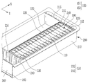
도 2는 본 발명의 일실시예에 따른 배터리의 대형 모듈에서 삽입부를 나타낸 도면이다.
도 3은 본 발명의 일실시예에 따른 배터리의 대형 모듈이 상호 결합되는 모습을 나타낸 도면이다.
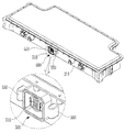
도 4는 본 발명의 일실시예에 따른 배터리의 대형 모듈에서 제1벽에 배치된 숫커넥터를 나타낸 도면이다.
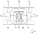
도 5는 본 발명의 일실시예에 따른 배터리의 대형 모듈에서 숫커넥터를 정면에서 바라본 도면이다.
도 6은 본 발명의 일실시예에 따른 배터리의 대형 모듈에서 암커넥터를 정면에서 바라본 도면이다.
도 7은 본 발명의 일실시예에 따른 배터리의 대형 모듈에서 결합상태의 커넥터를 측면에서 바라본 단면도이다.
도 8은 본 발명의 일실시예에 따른 배터리의 대형 모듈에서 결합상태의 커넥터를 상면에서 바라본 단면도이다.
도 9는 본 발명의 일실시예에 따른 배터리의 대형 모듈에서 복수의 단위셀이 배치된 구조를 나타낸 도면이다.
도 10은 본 발명의 일실시예에 따른 배터리의 대형 모듈에서 복수의 단위셀이 버스바를 통해 연결된 모습을 나타낸 도면이다.
도 11은 본 발명의 일실시예에 따른 배터리의 대형 모듈에서 엔드벽과 엔드서포트를 나타낸 도면이다.
도 12는 본 발명의 일실시예에 따른 배터리의 대형 모듈에서 엔드벽의 형상을 나타낸 도면이다.
도 13은 본 발명의 일실시예에 따른 배터리의 대형 모듈에서 엔드서포트의 엔드면을 나타낸 도면이다.
도 14는 본 발명의 일실시예에 따른 배터리의 대형 모듈에서 냉각채널을 개략적으로 나타낸 도면이다.
도 15는 본 발명의 일실시예에 따른 배터리의 대형 모듈에서 냉각채널을 아래에서 바라본 도면이다. 1 is a view showing a large module of a battery according to an embodiment of the present invention.
2 is a view showing an insertion unit in a large module of a battery according to an embodiment of the present invention.
3 is a view showing a state in which large modules of a battery are coupled to each other according to an embodiment of the present invention.
4 is a view showing a male connector disposed on a first wall in a large module of a battery according to an embodiment of the present invention.
5 is a view of the male connector from the front in a large module of a battery according to an embodiment of the present invention.
6 is a view of the female connector from the front in a large module of a battery according to an embodiment of the present invention.
7 is a cross-sectional view of a connector in a coupled state viewed from a side in a large module of a battery according to an embodiment of the present invention.
8 is a cross-sectional view of a connector in a coupled state from a top surface in a large module of a battery according to an embodiment of the present invention.
9 is a view showing a structure in which a plurality of unit cells are disposed in a large module of a battery according to an embodiment of the present invention.
10 is a view showing a plurality of unit cells connected through a bus bar in a large module of a battery according to an embodiment of the present invention.
11 is a view showing an end wall and an end support in a large module of a battery according to an embodiment of the present invention.
12 is a view showing the shape of the end wall in a large module of a battery according to an embodiment of the present invention.
13 is a view showing an end surface of an end support in a large module of a battery according to an embodiment of the present invention.
14 is a view schematically showing a cooling channel in a large module of a battery according to an embodiment of the present invention.
15 is a view of a cooling channel viewed from below in a large module of a battery according to an embodiment of the present invention.
아래에서는 첨부한 도면을 참고로 하여 본 발명의 실시예에 대하여 본 발명이 속하는 기술 분야에서 통상의 지식을 가진 자가 용이하게 실시할 수 있도록 상세히 설명한다. Hereinafter, exemplary embodiments of the present invention will be described in detail with reference to the accompanying drawings so that those skilled in the art to which the present invention pertains may easily practice.
그러나 본 발명은 여러 가지 상이한 형태로 구현될 수 있으며 여기에서 설명하는 실시예에 한정되지 않는다. 그리고 도면에서 본 발명을 명확하게 설명하기 위해서 설명과 관계없는 부분은 생략하였으며, 명세서 전체를 통하여 유사한 부분에 대해서는 유사한 도면 부호를 붙였다.However, the present invention can be implemented in many different forms and is not limited to the embodiments described herein. In addition, in order to clearly describe the present invention in the drawings, parts irrelevant to the description are omitted, and like reference numerals are assigned to similar parts throughout the specification.
본 명세서에서, 동일한 구성요소에 대해서 중복된 설명은 생략한다.In this specification, redundant description of the same components is omitted.
또한 본 명세서에서, 어떤 구성요소가 다른 구성요소에 '연결되어' 있다거나 '접속되어' 있다고 언급된 때에는, 그 다른 구성요소에 직접적으로 연결되어 있거나 또는 접속되어 있을 수도 있지만, 중간에 다른 구성요소가 존재할 수도 있다고 이해되어야 할 것이다. 반면에 본 명세서에서, 어떤 구성요소가 다른 구성요소에 '직접 연결되어' 있다거나 '직접 접속되어' 있다고 언급된 때에는, 중간에 다른 구성요소가 존재하지 않는 것으로 이해되어야 할 것이다.Also, in this specification, when a component is referred to as being 'connected' or 'connected' to another component, it may be directly connected to or connected to the other component, but other components in the middle It should be understood that may exist. On the other hand, in this specification, when a component is referred to as being 'directly connected' or 'directly connected' to another component, it should be understood that no other component exists in the middle.
또한, 본 명세서에서 사용되는 용어는 단지 특정한 실시예를 설명하기 위해 사용되는 것으로써, 본 발명을 한정하려는 의도로 사용되는 것이 아니다. In addition, the terms used in this specification are only used to describe specific embodiments, and are not intended to limit the present invention.
또한 본 명세서에서, 단수의 표현은 문맥상 명백하게 다르게 뜻하지 않는 한, 복수의 표현을 포함할 수 있다. Also, in this specification, a singular expression may include a plural expression unless the context clearly indicates otherwise.
또한 본 명세서에서, '포함하다' 또는 '가지다' 등의 용어는 명세서에 기재된 특징, 숫자, 단계, 동작, 구성요소, 부품, 또는 이들을 조합한 것이 존재함을 지정하려는 것일 뿐, 하나 또는 그 이상의 다른 특징, 숫자, 단계, 동작, 구성요소, 부품 또는 이들을 조합한 것의 존재 또는 부가 가능성을 미리 배제하지 않는 것으로 이해되어야 할 것이다.Also, in the present specification, terms such as 'include' or 'have' are only intended to designate the existence of features, numbers, steps, operations, components, parts, or combinations thereof described in the specification, and one or more of them. It should be understood that the existence or addition possibilities of other features, numbers, steps, actions, components, parts or combinations thereof are not excluded in advance.
또한 본 명세서에서, '및/또는' 이라는 용어는 복수의 기재된 항목들의 조합 또는 복수의 기재된 항목들 중의 어느 항목을 포함한다. 본 명세서에서, 'A 또는 B'는, 'A', 'B', 또는 'A와 B 모두'를 포함할 수 있다.Also, in this specification, the term 'and / or' includes a combination of a plurality of listed items or any one of a plurality of listed items. In this specification, 'A or B' may include 'A', 'B', or 'both A and B'.
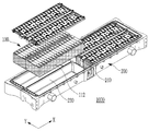
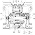
도 1에는 본 발명의 일실시예에 따른 배터리의 대형 모듈(1000)이 도시되어 있고, 도 2에는 도 1에 도시된 삽입부(220)를 나타낸 도면이 도시되어 있다.1 shows a
도 1 내지 2에 도시된 것처럼, 본 발명의 일실시예에 따른 배터리의 대형 모듈(1000)은 복수의 단위셀(110)이 제1방향(X)으로 정렬되고, 상기 복수의 단위셀(110)을 둘러싸는 절연부재(112)를 포함하는 셀스택(100) 및 상기 셀스택(100)이 삽입되는 삽입부(220)가 복수개로 마련되는 모듈하우징(200)을 포함하며, 상기 삽입부(220)는, 상기 셀스택(100)을 둘러싸며 적어도 일부가 상기 셀스택(100)과 접촉되는 고정벽(250)을 포함하고, 상기 모듈하우징(200)에 구비되고, 이웃하는 모듈하우징(1001)과 결합되는 결합부(400)를 더 포함하며, 상기 결합부(400)는, 상기 모듈하우징(200) 및 상기 이웃하는 모듈하우징(1001)을 전기적 및 신호적으로 연결하는 커넥터(500)를 포함한다.1 to 2, in a
셀스택(100)은 제1방향(X)으로 정렬된 복수의 단위셀(110)을 포함한다. 단위셀(110)은 전극조립체를 포함하며 단자부(150)가 구비되는 하나의 이차전지에 해당하며, 각형 또는 원통형 등 다양한 형상의 케이스를 포함할 수 있다.The
도 1 및 2에는 사각기둥 형태의 케이스를 가지는 단위셀(110)이 도시되어 있으나, 반드시 이에 한정되는 것은 아니며, 이하에서는 설명의 편의를 위해 도 1 및 2에 도시된 사각 형태의 케이스를 가지는 단위셀(110)을 기준으로 설명한다.1 and 2, the
단위셀(110)들은 각각 전극조립체와 전기적으로 연결되는 단자부(150)를 포함하며, 단자부(150)는 한 쌍으로 구비되어 각각 전극조립체의 제1전극과 제2전극에 전기적으로 연결될 수 있다. 즉, 단자부(150)는 제1전극에 연결되는 제1단자(151) 및 제2전극에 연결되는 제2단자(152)를 포함할 수 있다.The
단자부(150)의 배치 및 형태는 다양할 수 있으나, 본 발명의 일실시예에서는 도 1에 도시된 바와 같이 케이스의 개구에 결합되는 캡플레이트상에 구비될 수 있고, 서로 다른 극성을 가지는 한 쌍의 단자부(150)가 캡플레이트의 양단부에 배치될 수 있다.Arrangement and shape of the
셀스택(100)에는 상기 단위셀(110)이 복수개 정렬되며, 정렬방향은 다양할 수 있으나 바람직하게는 도 1 및 2에 도시된 바와 같이 단위셀(110)의 측면 중 넓은 측면이 상호 마주보는 방향으로 정렬될 수 있다. 이하에서는 단위셀(110)의 정렬방향을 제1방향(X)으로 정의한다. 제1방향(X)으로 셀스택(100)의 양단에는 단위셀(110)이 배치되거나 엔드서포트(120)가 배치될 수 있다.A plurality of the
셀스택(100)을 구성하는 단위셀(110)의 수는 필요에 따라 다양할 수 있다. 하나의 셀스택(100)에 포함되는 단위셀(110)은 후술할 스택버스바(172) 등을 이용하여 상호 전기적으로 연결될 수 있다.The number of
한편, 셀스택(100)은 복수의 단위셀(110)을 둘러싸는 절연부재(112)를 포함한다. 절연부재(112)는 고무, 플라스틱 등과 같은 절연소재로 이루어지며 복수의 단위셀(110)을 둘러싼다.Meanwhile, the
필요에 따라서 절연부재(112)는 셀스택(100)에서 제1방향(X) 양단에 배치되는 엔드서포트(120)를 복수의 단위셀(110)과 함께 감싸도록 마련될 수도 있고, 엔드서포트(120)를 제외하고 복수의 단위셀(110)만을 둘러싸며 셀스택(100)의 양단에 엔드서포트(120)가 별도로 배치될 수도 있다.If necessary, the insulating
절연부재(112)는 필름 형태로 구비되거나 강성을 가지는 판상의 구성이 복수개로 구비될 수도 있다. 절연부재(112)는 셀스택(100)의 4개 측면을 모두 둘러싸는 형태로 마련되거나 그 중 일부에만 배치될 수도 있고, 셀스택(100)의 상면 및 하면을 모두 둘러싸도록 마련될 수도 있다. 다만, 셀스택(100)의 상면에 배치되는 절연부재(112)는 단위셀(110) 각각의 단자부를 노출시키도록 마련될 수 있다.The insulating
도 1에는 본 발명의 일실시예에 따라 절연부재(112)가 절연필름의 형태로 마련되어 셀스택(100)에서 엔드서포트(120)를 제외하고 복수의 단위셀(110)의 측면을 감싸도록 마련된 모습이 도시되어 있다.In Figure 1, according to an embodiment of the present invention, the insulating
모듈하우징(200)은 셀스택(100)이 삽입되는 삽입부(220)가 복수개 마련된다. 도 1에는 모듈하우징(200)에 4개의 삽입부(220)가 형성된 모습이 도시되어 있으며, 도 2에는 도 1에 도시된 모듈하우징(200)에서 2개의 삽입부(220)가 따로 도시되어 있다. 모듈하우징(200)에 마련되는 삽입부(220)의 수는 필요에 따라 변경 가능하다.The
모듈하우징(200)은 바닥면(260)에서 상방으로 돌출되어 상기 바닥면(260)을 둘러싸는 외벽(210)이 존재하며, 상기 외벽(210) 내측으로 내부공간이 형성된다. 상기 내부공간에는 상기 삽입부(220)가 복수개로 마련될 수 있다.The
모듈하우징(200)의 형상은 다양할 수 있으며, 본 발명의 일실시예에 따른 모듈하우징(200)은 도 1 및 2에 도시된 바와 같이 대략 사각 형태의 바닥면(260)을 가지도록 마련될 수 있다.The shape of the
모듈하우징(200)은 상부가 개방된 형태로 마련될 수 있으며, 이에 따라 모듈하우징(200)에 마련되는 삽입부(220) 또한 상부가 개방된 형태로 마련될 수 있다. 모듈하우징(200)의 개방된 상면에는 모듈커버가 결합되어 밀폐될 수 있고, 상기 모듈커버가 모듈하우징(200)에 결합된 경우 상기 모듈커버는 상기 삽입부(220)의 상면에 해당하게 된다.The upper portion of the
한편, 도 1 내지 2에는 본 발명의 일실시예에 따른 삽입부(220)가 도시되어 있다. 상기 삽입부(220)는, 상기 셀스택(100)을 둘러싸며 적어도 일부가 상기 셀스택(100)과 접촉되는 고정벽(250)을 포함한다.Meanwhile, FIGS. 1 to 2 show an
도 1을 살펴보면, 셀스택(100)이 삽입된 삽입부(220) 및 셀스택(100)이 삽입되지 않은 삽입부(220)가 나란하게 배치된 모습이 도시되어 있다. 고정벽(250)은 상기 삽입부(220) 영역을 둘러싸는 경계벽에 해당하고, 삽입부(220)에 삽입되는 셀스택(100)은 고정벽(250)에 의해 사방이 둘러싸인 상태로 안정적으로 고정상태를 유지한다.Referring to Figure 1, the
고정벽(250)은 셀스택(100)의 형태에 따라 다양하게 배치될 수 있으나, 바람직하게는 도 1에 도시된 것처럼 셀스택(100)의 4방향 측면을 각각 마주보며 지지하는 4개의 면을 가지며 상기 셀스택(100)을 감싸도록 배치될 수 있다.The fixed
삽입부(220)의 고정벽(250)은 적어도 일부가 상기 셀스택(100)에 직접 접촉된다. 예컨대, 고정벽(250) 중 제1방향(X)에 위치된 어느 하나의 면이 셀스택(100)과 직접 접촉될 수도 있고, 고정벽(250) 중 제1방향(X)에 수직한 제2방향(Y)에 위치된 어느 하나의 면이 복수의 단위셀(110)의 측면, 예컨대 절연부재(112)와 직접 접촉될 수도 있다.At least a portion of the fixing
제2방향(Y)은 도 1에 표시된 것처럼 제1방향(X)과 동일평면상에서 제1방향(X)에 수직한 방향으로 정의될 수 있으며, 단위셀(110)의 폭방향으로 정의될 수 있다.The second direction (Y) may be defined in a direction perpendicular to the first direction (X) on the same plane as the first direction (X) as shown in FIG. 1 and may be defined as the width direction of the unit cell (110). have.
본 발명의 일실시예에서 셀스택(100)은 별도의 구성부품을 구비하지 않더라도 고정벽(250)에 의해 형상을 유지하며 제1방향(X)으로의 가압된 상태를 유지할 수 있다.In one embodiment of the present invention, the
본 발명과 같은 배터리의 대형 모듈(1000)이 아닌 일반적인 배터리 모듈의 경우, 하나의 셀스택에 모듈프레임이 결합되고, 상기 모듈프레임이 결합되어 단위 구성으로 취급되는 하나의 셀스택이 하나의 모듈을 구성한다.In the case of a general battery module other than the
일반적으로 취급되는 셀스택은 에너지밀도와 같은 성능적인 측면과 취급용이성을 위해 모듈프레임이 결합될 수 있고, 모듈프레임은 셀스택의 양단을 가압하는 엔드블록 및 셀스택의 사이드면을 따라 연장되는 사이드플레이트 등으로 구성될 수 있으며, 셀스택이 가압된 상태로 상기 엔드블록 및 사이드플레이트가 상호 결합되어 셀스택의 구조를 유지시킬 수 있다.Cell stacks that are generally handled can be combined with a module frame for ease of handling and performance aspects such as energy density, and the module frame is an end block that presses both ends of the cell stack and a side that extends along the side surface of the cell stack. It may be composed of a plate or the like, and the end block and the side plate may be coupled to each other while the cell stack is pressed to maintain the structure of the cell stack.
일반적인 배터리 모듈은 위와 같은 모듈프레임이 결합된 셀스택이 삽입되면서 모듈하우징과 상기 모듈프레임간의 체결이 이루어지고, 하나의 셀스택에서 제공되는 전력량을 가지는 배터리 모듈이 된다.A typical battery module is a battery module having an amount of power provided by one cell stack, while the cell stack in which the above module frame is combined is inserted into the module housing and the module frame.
이러한 일반적인 배터리 모듈의 경우, 하나의 셀스택보다 더 높은 요구전력을 충족시키기 위해 복수의 배터리 모듈이 제공되어야 하며, 이에 따라 셀스택을 단위체로 체결하는 모듈프레임 및 모듈 자체를 구성하는 복수의 구성부품이 추가 소요된다.In the case of such a general battery module, a plurality of battery modules must be provided in order to meet a higher required power than one cell stack, and accordingly, a plurality of component parts constituting the module frame and the module itself for fastening the cell stack as a unit. This takes extra.
본 발명의 일실시예에 따른 배터리의 대형 모듈(1000)은 일반적인 배터리 모듈과 달리 복수의 셀스택(100)이 하나의 모듈에 장착되므로 높은 요구전력을 충족시키는 데에 유리하며, 셀스택(100)이 모듈하우징(200)의 외벽(210)과 적어도 일부분이 구별될 수 있는 삽입부(220)의 고정벽(250)에 의해 고정되므로 모듈프레임과 같은 셀스택(100)의 고정을 위한 구성부품이 별도로 요구되지 않는다.Unlike the general battery module, the
한편, 도 3에는 본 발명의 일실시예에 따른 배터리의 대형 모듈(1000)이 복수개 마련되어 상호 결합되는 모습이 도시되어 있다. 즉, 도 3에는 배터리의 대형 모듈(1000)이 상호 결합되어 대형 팩을 형성하는 모습이 도시되어 있다.On the other hand, Figure 3 is a
도 3에 도시된 바와 같이, 본 발명의 일실시예에 다른 배터리의 대형 모듈(1000)은 상기 모듈하우징(200)에 구비되고, 이웃하는 모듈하우징(200)과 결합되는 결합부(400)를 더 포함할 수 있다.3, a
배터리의 대형 모듈(1000)은 요구전력을 충족시키기 위해 상호 결합되어 대형 팩 구조를 구현할 수 있는데, 도 3에는 모듈하우징(200)의 일면에 결합부(400)가 형성되고, 이웃하는 배터리의 대형 모듈(1000)간 결합부(400)가 서로 결합되는 모습이 도시되어 있다.The
한편, 본 발명의 일실시예에서 결합부(400)는 모듈하우징(200) 및 이웃하는 모듈하우징(1001)을 전기적 및 신호적으로 연결하는 커넥터(500)를 포함한다. 본 발명의 일실시예에서 커넥터(500)는 숫커넥터(510) 및 암커넥터(530)로 구성될 수 있으며, 도 3에는 커넥터(500) 중 암커넥터(530)가 도시되어 있고 도 4에는 숫커넥터(510)가 도시되어 있다.Meanwhile, in one embodiment of the present invention, the coupling part 400 includes a
본 발명의 일실시예는 커넥터(500)에 의해 어느 하나의 모듈하우징(200)이 이웃하는 모듈하우징(1001)과 기계적으로 결합됨과 동시에 전기적 및 신호적으로도 서로 연결관계를 가지게 된다.According to an embodiment of the present invention, any one of the
일반적인 경우 모듈하우징(200)간의 연결 시 셀스택(100)간의 전기적 연결을 위해 모듈버스바가 이용될 수 있는데, 모듈버스바는 셀스택(100)과 전기적으로 연결되도록 결합되기 위한 작업이 필요하다.In the general case, when connecting between the
본 발명의 경우, 모듈하우징(200)간의 결합이 이루어지는 경우 각 모듈하우징(200)에 구비되는 커넥터(500)가 상호 접촉 및 연결됨으로써, 별도의 조립 공정 없이도 각 모듈하우징(200)간의 전기적 및 신호적 연결이 가능해진다.In the case of the present invention, when the coupling between the
커넥터(500)를 통한 전기적 연결에 의해 어느 하나의 모듈하우징(200) 및 이웃하는 모듈하우징(1001)의 셀스택(100)들이 직렬 또는 병렬 형태로 전기적으로 연결될 수 있으며, 각 모듈하우징(200)의 내부온도, 전압 등 복수의 셀스택(100)을 관리하기 위한 제어관리신호가 서로 송수신 가능하여 효과적인 배터리 운용이 가능하다.Cell stacks 100 of either one of the
한편, 본 발명의 일실시예에서 상기 커넥터(500)는, 상기 모듈하우징(200)의 내부공간을 둘러싸는 외벽(210) 중 상기 제1방향(X)에 수직한 제2방향(Y)에 위치되는 제1벽(211)에 구비되는 숫커넥터(510) 및 상기 외벽(210) 중 상기 제1벽(211)의 반대측에 위치되는 제2벽(212)에 구비되어 상기 이웃하는 모듈하우징(1001)의 숫커넥터(510)와 결합되는 암커넥터(530)를 포함할 수 있다.On the other hand, in one embodiment of the present invention, the
모듈하우징(200)의 외벽(210)에서 제2방향(Y)에 위치되는 제1벽(211) 및 제2벽(212)에는 각각 숫커넥터(510) 및 암커넥터(530)가 구비되며, 숫커넥터(510) 및 암커넥터(530)는 상호 결합관계를 형성할 수 있다.A
예컨대, 어느 하나의 모듈하우징(200)에 구비되는 제2벽(212)의 암커넥터(530)는 이웃하는 모듈하우징(1001)의 제1벽(211)에 구비되는 숫커넥터(510)가 삽입 및 결합될 수 있다.For example, the
도 3에는 모듈하우징(200)의 제2벽(212) 및 상기 제2벽(212)에 배치되는 암커넥터(530)가 도시되어 있으며, 도 4에는 모듈하우징(200)의 제1벽(211) 및 상기 제1벽(211)에 배치되는 숫커넥터(510)가 도시되어 있다.3, the
본 발명의 일실시예는 제1방향(X)으로 정렬되는 복수의 단위셀(110)로 이루어진 셀스택(100)이 상기 제1방향(X)으로 복수개 배치될 수 있고, 이에 따라 모듈하우징(200)간의 결합 방향을 제2방향(Y)으로 설계하여 대형 팩의 전장이 증가하는 것을 억제할 수 있다.According to an embodiment of the present invention, a plurality of
따라서 모듈하우징(200)의 외벽(210) 중 제2방향(Y)에 배치되는 제1벽(211) 및 제2벽(212)에 각각 결합부(400)가 배치되며, 숫커넥터(510) 및 암커넥터(530) 또한 제1벽(211) 및 제2벽(212)에 각각 배치될 수 있다.Therefore, the coupling portion 400 is disposed on the
한편, 도 5에는 정면에서 바라본 숫커넥터(510)가 도시되어 있고, 도 6에는 정면에서 바라본 암커넥터(530)가 도시되어 있다.Meanwhile, FIG. 5 shows a
본 발명의 일실시예에서, 상기 숫커넥터(510)는 상기 제2방향(Y)으로 돌출되고 상기 모듈하우징(200) 내부에서 셀스택(100)과 전기적으로 연결되는 전류연결부(515)를 포함하고, 상기 암커넥터(530)는 상기 제2방향(Y)으로 만입되고 상기 이웃하는 모듈하우징(1001)의 상기 숫커넥터(510)의 상기 전류연결부(515)가 삽입되는 전류수용부(535)를 포함할 수 있다.In one embodiment of the present invention, the
숫커넥터(510) 및 암커넥터(530)는 상호 결합을 통해 전기적 및 신호적 연결이 이루어지며, 숫커넥터(510)에는 모듈하우징(200)의 셀스택(100)과 전기적으로 연결되는 전류연결부(515)가 형성될 수 있다.The
도 5 및 6을 참고할 때, 숫커넥터(510) 및 암커넥터(530)는 플라스틱 또는 중합체와 같은 절연소재의 베이스부를 가질 수 있고, 베이스부로부터 노출되어 전기적으로 연결되는 도전체 물질을 포함할 수 있다.5 and 6, the
전류연결부(515)는 모듈하우징(200)의 내부에서 셀스택(100)과 전기적으로 연결되며, 숫커넥터(510)의 베이스부로부터 제2방향(Y)으로 돌출되어 도전부가 외부로 노출된 형태를 가질 수 있다.The
암커넥터(530)는 전류수용부(535)를 포함할 수 있다. 전류수용부(535)는 전류연결부(515)와 연결 또는 결합되는 부위로서, 예컨대 제1벽(211)으로부터 돌출되도록 형성되는 전류연결부(515)가 삽입되는 홈의 형태를 가질 수 있다.The
암커넥터(530)는 모듈하우징(200) 내부의 셀스택(100)과 전기적으로 연결되는데, 이에 따라 어느 하나의 모듈하우징(200)에 구비되는 암커넥터(530)에 이웃하는 모듈하우징(1001)의 숫커넥터(510)가 연결되면, 상기 어느 하나의 모듈하우징(200) 및 이웃하는 모듈하우징(1001) 내부의 셀스택(100)이 함께 전기적으로 연결될 수 있다.The
암커넥터(530)는 숫커넥터(510)와 같이 전류수용부(535)에 금속 소재의 도전부가 베이스부로부터 노출된 형태를 가질 수 있고, 전류수용부(535)의 도전부는 셀스택(100)과 전기적으로 연결될 수 있다.The
도 7에는 서로 다른 모듈하우징(200)간의 숫커넥터(510)와 암커넥터(530)가 상호 결합된 모습을 측면에서 바라본 단면도가 도시되어 있다.7 is a cross-sectional view of a
도 7을 참고하면, 전류연결부(515)는 제1벽(211)으로부터 돌출된 돌기의 형상을 가질 수 있고, 전류수용부(535)는 상기 전류연결부(515)가 삽입되는 홈의 형태를 가질 수 있다. 도 7에는 전류연결부(515) 및 전류수용부(535)가 각각 해당 모듈하우징(200) 내부의 셀스택(100)과 전기적으로 연결되는 모습이 도시되어 있다.Referring to FIG. 7, the current connecting
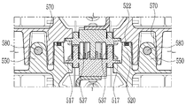
한편, 본 발명의 일실시예에서 상기 숫커넥터(510)는 상기 제2방향(Y)으로 돌출되고 상기 셀스택(100)의 관리제어신호를 전달하는 신호연결부(517)를 더 포함하고, 상기 암커넥터(530)는 상기 제2방향(Y)으로 만입되고 상기 이웃하는 모듈하우징(1001)의 상기 숫커넥터(510)의 상기 신호연결부(517)가 삽입되는 신호수용부(537)를 더 포함할 수 있다.Meanwhile, in one embodiment of the present invention, the
신호연결부(517) 및 신호수용부(537)는 전류연결부(515) 및 전류수용부(535)와 구별되며, 더 낮은 전압이 형성될 수 있다. 예컨대, 신호연결부(517) 및 신호수용부(537)는 저전압(LV)단자에 해당하고 전류연결부(515) 및 전류수용부(535)는 고전압(HV)단자에 해당될 수 있다.The
신호연결부(517)는 숫커넥터(510)의 베이스부로부터 노출되는 복수의 도전부로 이루어질 수 있으며, 복수의 핀 형상 또는 금속플레이트 형상을 가질 수 있다. 신호연결부(517)는 셀스택(100)의 온도, 전압, 냉각 정보 등을 파악하여 관리제어신호를 송수신하는 제어부와 상기 관리제어신호가 송수신되는 통로인 연결선을 통해 연결될 수 있다.The
신호수용부(537)는 암커넥터(530)에서 신호연결부(517)와 결합될 수 있도록 신호연결부(517)와 대응되는 형상으로 마련될 수 있다. 예컨대, 신호연결부(517)가 복수의 핀 형상을 가지는 경우 신호수용부(537)는 상기 복수의 핀이 삽입되는 복수의 홈 형상을 가질 수 있고, 신호연결부(517)가 금속플레이트 형상을 가지는 경우 신호수용부(537)는 신호연결부(517)와 면접하는 금속플레이트 형상을 가질 수 있다.The
신호연결부(517) 및 신호수용부(537)를 통해 송수신되는 관리제어신호는 다양하게 활용될 수 있다. 예컨대 복수의 모듈하우징(200)이 제2방향(Y)을 따라 결합된 대형 팩의 경우, 어느 하나의 모듈하우징(200)에 대형 팩을 총괄하여 관리제어하는 제어부가 배치될 수 있고, 각 모듈하우징(200)의 센서 등으로부터 수집되는 관리제어신호가 신호연결부(517) 및 신호수용부(537)를 통해 상기 제어부로 전달되어 대형 팩 전체의 제어에 활용될 수 있다.The management control signals transmitted and received through the
또는, 모듈하우징(200) 각각에 제어부가 구비될 수 있으며, 어느 하나의 모듈하우징(200)에 구비되는 제어부는 이웃하는 모듈하우징(1001)의 온도, 냉각 상황 등을 파악하여 상기 어느 하나의 모듈하우징(200)의 냉각 제어에 활용할 수 있다.Alternatively, a control unit may be provided in each of the
도 8에는 숫커넥터(510) 및 암커넥터(530)가 상호 결합된 모습을 위에서 바라본 단면도가 도시되어 있으며, 신호연결부(517)가 숫커넥터(510)의 베이스부로부터 돌출된 형상으로 마련되고, 신호수용부(537)는 신호연결부(517)가 삽입되는 홈의 형태로 마련된 모습이 도시되어 있다.8 is a cross-sectional view of the
한편, 상기 커넥터(500)는 중앙에 상기 모듈하우징(200)의 내부와 외부가 연통되는 연통홀(519, 539)이 형성될 수 있다. 연통홀(519, 539)은 숫커넥터(510) 및 암커넥터(530)에 각각 형성될 수 있고, 연통홀(519, 539)에 의해 모듈하우징(200) 내부와 외부가 연통될 수 있다.Meanwhile, the
따라서, 모듈하우징(200)의 내부온도 변화 등이 있더라도 내압이 안정적으로 유지될 수 있고, 특히 어느 하나의 단위셀(110)에서 고온의 가스가 배출되는 상황이 발생해도 안전하게 내부 환경을 유지하는 데에 유리할 수 있다.Therefore, even if there is a change in the internal temperature of the
연통홀(519, 539)의 위치 및 형상은 다양할 수 있는데, 도 5 및 6에는 숫커넥터(510) 및 암커넥터(530)의 베이스부에서 대략 중앙부에 위치된 연통홀(519, 539)의 형상이 도시되어 있다.The positions and shapes of the communication holes 519 and 539 may be various. In FIGS. 5 and 6, the communication holes 519 and 539 located at the center of the
한편, 본 발명의 일실시예에서 상기 결합부(400)는 상기 제1벽(211)에서 상기 숫커넥터(510)의 측부에 위치되며, 상기 제2방향(Y)으로 돌출되는 가이드돌기(550) 및 상기 제2벽(212)에서 상기 암커넥터(530)의 측부에 위치되며, 상기 이웃하는 모듈하우징(1001)의 가이드돌기(550)가 삽입되는 가이드홈(570)을 더 포함할 수 있다.On the other hand, in one embodiment of the invention the coupling portion 400 is located on the side of the
도 5에는 본 발명의 일실시예에 따라 한 쌍의 가이드돌기(550)가 숫커넥터(510)의 양측에 배치된 모습이 도시되어 있다. 가이드돌기(550)의 형상 및 개수는 다양할 수 있으나, 본 발명의 일실시예에 따르면 가이드돌기(550)는 제1벽(211)으로부터 제2방향(Y)으로 돌출될 수 있고, 제1벽(211)의 높이방향으로 연장된 형태일 수 있으며, 가이드홈(570)에 삽입이 용이하도록 외면이 곡면을 이루도록 형성될 수 있다. 즉, 가이드돌기(550)는 상부에서 바라본 단면 형상이 원의 일부에 해당될 수 있다.5 shows a pair of
가이드홈(570)은 가이드돌기(550)가 삽입되는 홈에 해당하며, 가이드돌기(550)의 형상과 대응되도록 형성될 수 있다. 도 6을 참고하면, 본 발명의 일실시예에 따른 가이드홈(570)은 암커넥터(530)의 양측에 각각 위치되며, 제2벽(212)의 높이방향으로 연장되고, 만입된 면이 가이드돌기(550)와 대응되도록 곡면에 해당할 수 있다.The
한 쌍의 모듈하우징(200)이 전기적 및 신호적으로 안정적인 결합을 이루기 위해서는 숫커넥터(510) 및 암커넥터(530)가 적정하게 배치되는 것이 유리한데, 본 발명의 일실시예는 한 쌍의 모듈하우징(200)이 결합되는 과정에서 가이드돌기(550)가 가이드홈(570)에 삽입되면서 결합을 위한 정위치를 이루게 되고, 이에 따라 숫커넥터(510) 및 암커넥터(530)가 정확하게 위치되어 상호 결합될 수 있다.In order for the pair of
한편, 본 발명의 일실시예에서 상기 가이드돌기(550)에는 상기 외벽(210)의 높이방향으로 체결홈(555)이 형성되고, 상기 가이드홈(570)의 측면에는 상기 체결홈(555)과 대응되는 위치에 체결공(575)이 형성되며, 상기 가이드돌기(550)는 상기 체결공(575)을 관통하여 상기 체결홈(555)에 삽입되는 체결부재(580)를 통해 상기 가이드홈(570)과 결합될 수 있다.On the other hand, in one embodiment of the present invention, the
가이드돌기(550)는 외벽(210), 즉 제1벽(211)의 높이방향으로 연장된 형태를 가질 수 있고, 내부에는 제1벽(211)의 높이방향으로 연장된 체결홈(555)이 형성될 수 있다. 또한, 가이드돌기(550)가 삽입되는 가이드홈(570)의 측면에는 체결홈(555)과 대응되는 위치에 관통된 개구 형상의 체결공(575)이 형성될 수 있다.The
가이드돌기(550)가 가이드홈(570)에 삽입된 경우, 볼트 등과 같이 체결부재(580)가 상기 체결공(575)을 관통하여 체결홈(555)에 삽입됨으로써, 2개의 모듈하우징(200)이 서로 견고히 결합될 수 있다.When the
도 8에는 가이드홈(570)의 체결공(575)을 관통하며 가이드돌기(550)의 체결홈(555)에 삽입된 체결부재(580)의 단면이 도시되어 있다.8 shows a cross section of the
한편, 도 5, 7 및 8에는 숫커넥터(510)의 테두리를 따라 연장되고, 제2방향(Y)으로 돌출되어 암커넥터(530)에 밀착되어 전류연결부(515) 및 신호연결부(517)를 밀폐시키는 실링벽(520)에 도시되어 있다.Meanwhile, FIGS. 5, 7 and 8 extend along the rim of the
실링벽(520)은 전류연결부(515) 및 신호연결부(517)의 주위를 둘러싸는 측벽의 형태를 가질 수 있고, 암커넥터(530)를 바라보는 단부에는 실링 능력이 향상될 수 있도록 고무 등의 소재로 이루어지는 O형의 실러(522)가 구비될 수 있다.The sealing
실러(522)는 O형과 같이 폐단면을 가지는 형태로 마련되며, 실링벽(520)의 단부로부터 돌출되어 숫커넥터(510) 및 암커넥터(530)의 결합 시 상기 실링벽(520)과 암커넥터(530) 사이에서 가압될 수 있다.The
고압의 전류가 송전되고 및 관리제어신호가 송수신되는 커넥터(500)는 실러(522)가 구비되는 실링벽(520)에 의해 외부로부터 차폐되어 안전성이 향상될 수 있다.The
한편, 도 9에는 모듈하우징(200) 내부에 배치되는 복수의 단위셀(110)들이 도시되어 있으며, 도 10에는 상기 복수의 단위셀(110)들이 전기적으로 연결된 구조가 도시되어 있다.Meanwhile, FIG. 9 shows a plurality of
본 발명의 일실시예에서, 삽입부(220)는 상기 제2방향(Y)을 따라 제1열 및 제2열을 이루도록 배치되고, 상기 제1열에 포함되는 셀스택(100)들은 상기 제2열에 포함되는 셀스택(100)들과 서로 전기적으로 분리될 수 있다.In one embodiment of the present invention, the
이하에서는 제2방향(Y)을 따라 정렬되고 제1방향(X)으로 이격된 삽입부(220) 또는 셀스택(100)의 각 열을 제1열 및 제2열로 정의한다. 설명의 편의를 위해, 도 9에서는 제2방향(Y)으로 배열된 열 중 왼쪽 열을 제1열, 오른쪽 열을 제2열로 설명한다.Hereinafter, each column of the
상기 셀스택(100)은 상기 제2방향(Y)으로 이웃하는 셀스택(100)간에 전기적으로 연결되고, 상기 제1방향(X)으로 이웃하는 셀스택(100)간에 서로 전기적으로 분리될 수 있다. 제2방향(Y)으로 이웃하는 셀스택(100)들은 서로 직렬 또는 병렬 형태로 연결될 수 있으며, 일부 병렬 형태를 취함과 동시에 일부 직렬 형태를 취하도록 연결될 수도 있다.The
또한, 제1방향(X)으로 이웃하는 셀스택(100)들은 상호 전기적으로 분리된다. 도 10를 참고하면, 4개의 셀스택(100) 중 제2방향으로 이웃하는 셀스택(100)들은 후술하는 연결버스바(174)를 통해 전기적으로 연결되지만, 제1방향(X)으로 이웃하는 셀스택(100)들은 상호 전기적으로 연결되지 않아 양측으로 원-사이드 터미널(one-side terminal) 구조를 취하게 된다.In addition, the cell stacks 100 neighboring in the first direction X are electrically separated from each other. Referring to FIG. 10, cell stacks 100 neighboring in the second direction among the four
이에 따라, 본 발명에서 복수의 셀스택(100)이 복수의 열을 형성하더라도 서로 전기적으로 분리된 상태를 유지하며, 필요에 따라 셀스택(100)의 수를 늘리는 것이 용이하고, 복수의 셀스택(100)에서 제공되는 전력을 전기소비장치에 효과적으로 제공할 수 있다.Accordingly, in the present invention, even if the plurality of
후술할 내용과 같이 복수의 대형 모듈이 상호 결합되어 대형 팩의 형태를 취하는 경우, 전기소비장치의 반대측 단부에 배치되는 대형 모듈에는 제2방향(Y)으로 이웃하는 셀스택(100)을 전기적으로 연결하기 위한 별도의 연결수단이 구비되거나 모듈하우징(200) 내부에서 셀스택(100)간의 전기적 연결구조를 취할 수도 있다.As described later, when a plurality of large modules are mutually coupled to take the form of a large pack, the cell stacks 100 adjacent to each other in the second direction (Y) are electrically connected to the large modules disposed at opposite ends of the electric consumption device. Separate connection means for connection may be provided, or an electrical connection structure between the cell stacks 100 may be taken inside the
한편, 도 10을 참고하면 본 발명의 일실시예에 따른 배터리의 대형 모듈(1000)은 상기 셀스택(100)에서 상기 복수의 단위셀(110)을 전기적으로 연결하는 스택버스바(172), 상기 제1열 또는 상기 제2열에서 상기 제2방향으로 이웃하는 2개의 셀스택(100)을 전기적으로 연결하는 연결버스바(174) 및 상기 셀스택(100)으로부터 인출되며, 상기 전류연결부(515) 또는 상기 전류수용부(517)와 연결되는 단자버스바(176)를 포함할 수 있다.On the other hand, referring to Figure 10, a
스택버스바(172)는 어느 하나의 셀스택(100)에 포함되는 단위셀(110)들을 전기적으로 연결한다. 도 10에는 단위셀(110)의 양측으로 번갈아 배치되며 단위셀(110)을 일정한 개수만큼 반복하여 연결하는 스택버스바(172)가 도시되어 있다.The
즉, 셀스택(100)은 스택버스바(172)를 통해 복수의 단위셀(110)이 상호 전기적으로 연결될 수 있으며, 스택버스바(172)는 단위셀(110)의 배치방향을 따라 연장되는 몸체부 및 상기 몸체부로부터 돌출되어 각 단위셀(110)의 단자부(150)에 연결되는 다리부를 포함할 수 있다.That is, the
연결버스바(174)는 이웃하는 2개의 셀스택(100)을 전기적으로 연결한다. 도 10에 도시된 본 발명의 일실시예는 제2방향(Y)으로 각각 2개의 셀스택(100)이 배열된 구조이며, 2개의 셀스택(100) 사이에 연결버스바(174)가 배치되어 제2방향(Y)으로의 전기적 연결이 구현된다.The connecting
연결버스바(174)는 일단부가 어느 하나의 셀스택(100)에 배치되는 단위셀(110)의 단자부(150)에 연결될 수 있고, 타단부가 이웃하는 셀스택(100)의 단위셀(110)에 마련된 단자부(150)에 연결될 수 있다.The
도 10과 같이 셀스택(100)을 서로 직렬 연결하는 경우, 제2방향(Y)으로 이웃하는 단위셀(110)들은 서로 다른 극성이 마주보도록 배치될 수 있고, 연결버스바(174)는 일측에서 제2방향(Y)으로 마주하는 단위셀(110)들의 서로 마주보는 단자부(150)를 연결할 수 있다.When the
단자버스바(176)는 셀스택(100)으로부터 인출되어 셀스택 그룹의 단자 역할을 수행한다. 예컨대, 도 10과 같이 제2방향으로 2개의 셀스택(100)이 상호 연결되는 경우, 어느 하나에서 인출된 단자버스바(176)는 입력단자에 해당하고, 나머지 하나에서 인출된 단자버스바(176)를 출력단자에 해당할 수 있다.The
이러한 단자버스바(176)는 숫커넥터(510) 또는 암커넥터(530)와 연결되어 이웃하는 모듈하우징(1001) 내부의 셀스택(100)과도 전기적으로 연결될 수 있다.The
즉, 본 발명은 복수의 대형 모듈을 연결시켜 대형 팩을 구현하더라도, 상기 단자버스바(176) 및 커넥터(500)의 연결 구조를 통해 서로 다른 열을 가지는 셀스택(100) 그룹간의 전기적 분리 관계를 유지하여 원-사이드 터미널 형태를 유지하게 된다.That is, in the present invention, even if a plurality of large modules are connected to implement a large pack, the electrical separation relationship between groups of
한편, 다시 도 7을 참고할 때 본 발명의 일실시예에 따른 배터리의 대형 모듈(1000)에서 전류연결부(515)는 상기 제1열에 포함되는 셀스택(100)들과 전기적으로 연결되는 제1돌기(512) 및 상기 제2열에 포함되는 셀스택(100)들과 전기적으로 연결되는 제2돌기(514)를 포함할 수 있다.Meanwhile, referring to FIG. 7 again, in the
앞서 설명한 바와 같이 본 발명의 일실시예는 제1열의 셀스택(100)들과 제2열의 셀스택(100)들이 서로 전기적으로 분리되고, 전류연결부(515)는 제1열의 셀스택(100)들과 연결되는 제1돌기(512) 및 제2열의 셀스택(100)들과 연결되는 제2돌기(514)가 서로 구분되어 마련된다.As described above, according to an embodiment of the present invention, the cell stacks 100 of the first row and the cell stacks 100 of the second row are electrically separated from each other, and the
전류수용부(535)는 전류연결부(515)에 대응되도록 상기 제1열에 포함되는 셀스택(100)들과 전기적으로 연결되며 상기 이웃하는 모듈하우징(1001)의 상기 제1돌기(512)와 결합되는 제1수용부(532) 및 상기 제2열에 포함되는 셀스택(100)들과 전기적으로 연결되며 상기 이웃하는 모듈하우징(1001)의 상기 제2돌기(514)와 결합되는 제2수용부(534)을 포함할 수 있다.The
이에 따라, 어느 하나의 모듈하우징(200)에 구비되는 암커넥터(530)에 이웃하는 모듈하우징(1001)의 숫커넥터(510)가 결합되면, 이웃하는 모듈하우징(1001)의 제1열 셀스택(100)들과 연결되는 제1돌기(512)가 해당 모듈하우징(200)의 암커넥터(530)에 구비되는 제1수용부(532)로 전달되고, 제1수용부(532)로 전달되는 전류는 다시 해당 모듈하우징(200)의 제1열 셀스택(100)들을 지나 해당 모듈하우징(200)의 숫커넥터(510)에서 제1돌기(512)를 통해 전달될 수 있다.Accordingly, when the
즉, 본 발명의 일실시예에서 숫커넥터(510)는 제1열 및 제2열의 셀스택(100)들이 서로 전기적으로 구분되면서 이웃하는 모듈하우징(1001)과 효과적으로 연결될 수 있도록 제1돌기(512) 및 제2돌기(514)가 구분되며, 암커넥터(530) 또한 제1열 및 제2열의 셀스택(100)들을 서로 전기적으로 구분하기 위해 제1수용부(532) 및 제2수용부(534)가 구분되어 마련될 수 있다.That is, in one embodiment of the present invention, the
한편, 도 9에 도시된 것처럼 셀스택(100)에서 일단부의 단위셀(110)에는 상기 단자버스바(176)가 연결되고, 타단부의 단위셀(110)에는 상기 연결버스바(174)가 연결되며, 상기 셀스택(100)은 상기 일단부가 상기 제1열 및 상기 제2열 사이를 바라보도록 배치되어, 상기 단자버스바(176)가 상기 제1열 및 상기 제2열 사이로 인출될 수 있다.Meanwhile, as shown in FIG. 9, the
단자버스바(176)는 커넥터(500)를 통해 외부로 연결될 수 있고, 연결버스바(174)는 제2방향(Y)으로 이웃하는 셀스택(100)을 상호 연결시키는 연결수단이 될 수 있다.The
따라서, 본 발명의 일실시예는 단자버스바(176)를 셀스택(100) 일단부의 단위셀(110)에 연결시키고, 연결버스바(174)를 셀스택(100) 타단부의 단위셀(110)에 연결시킴으로써, 셀스택(100)을 구성하는 복수의 단위셀(110)을 전체로서 효과적으로 연결시키는 구조를 구현하게 된다.Accordingly, an embodiment of the present invention connects the
한편, 본 발명의 일실시예는 제1열 및 제2열의 셀스택(100)들이 각각 제1방향(X)으로 서로 마주하는 부분이 일단부에 해당되어 단자버스바(176)가 제1열 및 제2열 사이로 배치될 수 있다. 후술할 내용과 같이 제1열 및 제2열 사이의 이격공간은 제2충격흡수공간(216)에 해당할 수 있다.On the other hand, according to an embodiment of the present invention, the first and second rows of
복수의 단위셀(110)의 집합체에서 외부에 대한 단자 역할을 수행하는 단자버스바(176)가 제1열 및 제2열의 중앙측으로 배치되면, 단자버스바(176)와 연결되어 모듈하우징(200) 외부에 배치되는 커넥터(500) 또한 중앙에 배치되기 유리하고, 따라서 복수의 대형 모듈간 전기적 연결 구조 또는 전기소비장치와의 전기적 연결 구조를 효율적으로 구성할 수 있다.When the
한편, 도 10에 도시된 바와 같이 상기 제1열의 셀스택(100)들로부터 인출되는 단자버스바(176)들과 상기 제2열의 셀스택(100)들로부터 인출되는 단자버스바(176)들은 상기 제2방향(Y)을 따라 서로 교번하여 배치될 수 있다.Meanwhile, as illustrated in FIG. 10, terminal bus bars 176 that are drawn out from the cell stacks 100 in the first row and terminal bus bars 176 that are drawn out from the cell stacks 100 in the second row are It may be arranged alternately with each other along the second direction (Y).
제1방향(X) 및 제2방향(Y)으로 삽입부(220)가 정렬되는 본 발명의 구조를 고려할 때, 제1방향(X)으로 이웃하는 셀스택(100)들이 서로 전기적으로 분리되더라도, 각각의 단자버스바(176)가 마주보게 되면 단자버스바(176)에 형성되는 고전압에 의해 단락이 일어날 가능성이 있다.Considering the structure of the present invention in which the
또한, 제2방향(Y)으로 배치되는 셀스택(100)간의 단자버스바(176) 또한 서로 상이한 극성을 가지므로 가깝게 배치되면 단락이 발생될 가능성이 있다.In addition, since the terminal bus bars 176 between the cell stacks 100 arranged in the second direction Y also have different polarities, short circuits may occur if they are disposed close together.
이에 따라, 본 발명은 복수의 셀스택(100)이 제1열 및 제2열과 같이 복수의 열을 이루며 하나의 모듈하우징(200)에 구비되더라도, 상호간의 단락 상황 등이 발생되지 않도록 하기 위해, 제1열의 단자버스바(176)와 제2열의 단자버스바(176)가 서로 마주보지 않게 함과 동시에, 제1열의 단자버스바(176)들이 서로 이웃하게 배치되거나 제2열의 단자버스바(176)들이 서로 이웃하게 배치되지 않도록 한다.Accordingly, in the present invention, even if a plurality of
도 10를 참고하면, 중앙에 배치된 4개의 단자버스바(176)는 위에서부터 차례대로 제1열의 단자버스바(176), 제2열의 단자버스바(176), 다시 제1열의 단자버스바(176), 다시 제2열의 단자버스바(176)가 되도록 배치될 수 있다.Referring to FIG. 10, the four terminal bus bars 176 arranged in the center are sequentially arranged from the top to the first row of terminal bus bars 176, the second row of terminal bus bars 176, and the first row of terminal bus bars. (176), it may be arranged to become the
본 발명의 일실시예에 따른 배터리의 대형 모듈(1000)은 상기 셀스택(100)에서 상기 복수의 단위셀(110)은 상기 제1방향(X)으로 동일 극성의 단자부(150)끼리 마주보는 적어도 하나 이상의 단위셀(110)로 구성되는 복수의 셀그룹으로 구분되고, 상기 스택버스바(172)는 상기 제1방향(X)으로 연장되며, 서로 이웃하고 상기 제1방향(X)으로 서로 다른 극성의 단자부(150)끼리 마주보도록 배치된 2개의 셀그룹을 직렬 연결할 수 있다.In a
셀스택(100)은 복수의 단위셀(110)로 구성되는데, 상기 복수의 단위셀(110)은 복수의 셀그룹을 구성하고, 복수의 셀그룹이 셀스택(100)을 구성할 수 있다. 본 발명의 일실시예에서 셀그룹이란 제1방향으로 이웃하며 배치되는 복수의 단위셀(110) 중 서로 동일한 극성을 가지는 단자부(150)가 제1방향으로 마주하도록 배치된 단위셀(110)들의 그룹을 의미한다.The
도 10을 살펴보면, 각각의 셀스택(100)에서 동일한 극성의 단자부(150), 예컨대 제1단자(151)끼리 마주하는 단위셀(110)이 2개씩 배치되며, 단위셀(110) 2개마다 극성이 바뀌도록, 예컨대 제1단자(151) 이후 제2단자(152)가 배치된 것을 볼 수 있으며, 이는 단위셀(110) 2개가 하나의 셀그룹을 형성하는 실시예임을 의미한다.Referring to FIG. 10, in each
셀스택(100) 전체에서 셀그룹을 구성하는 단위셀(110)의 수는 바람직하게는 모두 동일할 수 있고, 다만 셀그룹을 구성하는 단위셀(110)의 수는 1개에서 복수개까지 필요에 따라 다양할 수 있다.The number of
스택버스바(172)는 제1방향(X)을 따라 연장되며 이웃하는 단위셀(110)들에서 서로 마주보는 단자부(150)를 서로 연결시킨다. 즉, 스택버스바(172)에 의해 셀그룹을 구성하는 단위셀(110)들은 서로 병렬 형태로 연결되며, 이웃하는 셀그룹간에는 직렬 형태로 연결된다.The
한편, 본 발명의 일실시예에 따른 배터리의 대형 모듈(1000)에서, 상기 연결버스바(174)를 통해 전기적으로 연결된 2개의 셀스택(100) 중 어느 하나는 상기 복수의 셀그룹 중 서로 이웃하는 2개 셀그룹이 서로 동일 극성의 단자부(150)끼리 마주보도록 배치될 수 있다.On the other hand, in the
또한, 본 발명의 일실시예에 따른 배터리의 대형 모듈(1000)은 상기 제1방향(X)을 가로지르도록 연장되고, 서로 동일 극성의 단자부(150)끼리 마주보며 이웃하는 상기 2개의 셀그룹을 직렬 연결하는 크로스버스바(178)를 더 포함할 수 있다.In addition, the
도 10을 살펴보면, 도면상 제1열의 상측에 도시된 셀스택(100)에서 연결버스바(174)가 연결된 셀그룹과 이웃하는 셀그룹은 서로 동일한 극성의 단자부(150), 예컨대 제1단자(151)끼리 서로 마주보도록 배치된 모습이 도시되어 있다.Referring to FIG. 10, in the
앞서 설명한 바와 같이 고전압에 의해 단자버스바(176)간 단락 상황 등을 방지하기 위해 제2방향(Y)으로 이웃하는 셀스택(100)간에도 단자버스바(176)가 인접하게 배치되지 않도록 하는데, 크로스버스바(178)의 이용으로 이러한 단자버스바(176)의 배치 구조를 구현하는 데에 유리할 수 있다.As described above, in order to prevent a short circuit situation between the terminal bus bars 176 by high voltage, the terminal bus bars 176 are not arranged adjacently between the cell stacks 100 adjacent in the second direction (Y). The use of the
예컨대, 셀그룹을 구성하는 단위셀(110)의 수에 관계없이 단위셀(110)의 개수가 동일한 셀스택(100)에서는 스택버스바(172)만을 이용하여 셀스택(100)의 단위셀(110)을 전기적으로 연결하게 되면 제2방향(Y)으로 이웃하는 셀스택(100)의 각 단자버스바(176)가 서로 이웃하게 인출되는 경우가 발생될 수 있다.For example, in the
그러나, 연결버스바(174)를 통해 연결되는 2개의 셀스택(100) 중 어느 하나에서, 서로 이웃하는 셀그룹이 서로 동일한 극성의 단자부(150)가 마주하도록 배치되고, 상기 2개의 셀그룹을 상기 제1방향(X)을 가로지르는 방향으로 직렬 연결하게 되면, 제2방향(Y)으로 이웃하는 셀스택(100)의 각 단자버스바(176)가 서로 이웃하게 인출되는 상황이 방지될 수 있다.However, in any one of the two
도 3에는 본 발명의 일실시예에 따라 제1열 및 제2열의 상부측 셀스택(100)에서 연결버스바(174)가 연결되는 셀그룹과 이웃하는 셀그룹은 서로 동일한 극성의 단자부(150)가 제1방향으로 마주보게 배치되고, 도 4에는 제1방향을 가로지르며 2개의 셀그룹을 직렬 형태로 연결하는 크로스버스바(178)가 도시되어 있다.In FIG. 3, the cell groups to which the
한편, 도 4에 도시된 바와 같이 본 발명의 일실시예에 따른 배터리의 대형 모듈(1000)은 상기 셀스택(100)에서 상기 타단부의 단위셀(110)에는 상기 연결버스바(174) 및 상기 크로스버스바(178)가 함께 연결될 수 있다. 이에 따라 본 발명의 일실시예는 연결버스바(174), 스택버스바(172) 및 크로스버스바(178)의 배치 구조를 보다 효과적으로 설정할 수 있다.On the other hand, as shown in Figure 4, the
한편, 다시 도 1 및 2를 참고하면 본 발명의 일실시예에 따른 배터리의 대형 모듈(1000)에서 상기 고정벽(250)은, 상기 모듈하우징(200)의 외벽(210)으로 둘러싸인 내부공간을 상기 제1방향(X)으로 가로지르며, 상기 셀스택(100)의 사이드면에 접촉되는 분리벽(230) 및 상기 제1방향(X) 양측에 배치되어 상기 셀스택(100)의 상기 제1방향(X) 양측의 엔드면을 각각 가압하는 엔드벽(240)을 포함할 수 있다.Meanwhile, referring to FIGS. 1 and 2 again, in the
분리벽(230)은 상기 제1방향(X)으로 연장되고, 외벽(210)으로 둘러싸인 내부공간을 구획하여 상기 복수의 삽입부(220)를 형성하는 데에 기여한다. 또한, 상기 분리벽(230)은 상기 제2방향(Y)을 따라 양측으로 배치된 2개의 삽입부(220)의 고정벽(250)의 일부를 구성하고, 상기 2개의 삽입부(220)에 각각 삽입되는 상기 셀스택(100)의 사이드면에 접촉될 수 있다.The dividing
사이드면은 셀스택(100)의 측면 중 제1방향(X)으로 연장된 양측면, 즉 셀스택(100)에서 제2방향(Y)의 양측면을 의미하며, 앞서 설명한 바와 같이 본 발명의 셀스택(100)은 별도의 모듈프레임이 구비되지 않는 바, 상기 사이드면은 복수의 단위셀(110) 측면을 감싸는 절연부재(112)에 해당할 수 있다.The side surface means both side surfaces extending in the first direction X among the side surfaces of the
분리벽(230)은 모듈하우징(200)의 바닥면(260)으로부터 상방으로 돌출된 형태로 마련될 수 있고, 제1방향(X)을 따라 연장되면서 모듈하우징(200)의 내부공간을 분할하도록 마련될 수 있다. 즉, 분리벽(230)은 삽입부(220)를 둘러싸는 고정벽(250)의 일부, 즉 일면에 해당할 수 있다.The dividing
도 1 내지 2를 참고하면, 분리벽(230)을 기준으로 그 양측에 각각 삽입부(220)가 형성되며, 분리벽(230)은 양측에 존재하는 2개의 삽입부(220)에 대한 고정벽(250)이 된다.Referring to FIGS. 1 to 2, the
도 2를 참고하면, 분리벽(230)은 삽입부(220)에 삽입되는 셀스택(100)의 사이드면과 마주하게 되는데, 따라서 고정벽(250)의 일부에 해당되는 분리벽(230)은 삽입부(220)에 삽입된 셀스택(100)의 사이드면의 적어도 일부에 직접 접촉되어 셀스택(100)을 제2방향(Y)으로 지지하게 된다.Referring to FIG. 2, the
한편, 엔드벽(240)은 상기 제2방향(Y)으로 연장되고, 복수의 삽입부(220) 각각의 제1방향(X) 양단에 배치되어 상기 셀스택(100)의 상기 제1방향(X) 양측의 엔드면을 각각 가압하며, 고정벽(250)의 일부에 해당할 수 있다.On the other hand, the
본 발명은 셀스택(100)에서 제1방향(X) 양단의 측면을 각각 엔드면으로 정의한다. 본 발명의 일실시예에 따르면, 상기 엔드면은 절연부재(112)이거나 엔드서포트(120)의 일면에 해당할 수 있다.In the present invention, the side surfaces of both ends of the first direction X in the
도 1 및 2에는 셀스택(100)의 제1방향(X) 양측으로 엔드벽(240)이 각각 배치된 모습이 도시되어 있다. 엔드벽(240)은 모듈하우징(200) 내에서 복수개로 존재할 수 있고, 삽입부(220)의 고정벽(250) 중 제1방향(X) 양측에 해당한다.1 and 2 show a state in which end
엔드벽(240)은 모듈하우징(200)의 외벽(210)과는 구별될 수 있다. 예컨대, 엔드벽(240)은 모듈하우징(200)의 내부공간에서 바닥면(260)으로부터 돌출된 형상을 가지며 제2방향(Y)으로 연장되되, 일면이 마주하는 외벽(210) 또는 마주하는 다른 엔드벽(240)과 이격되도록 복수개로 배치될 수 있다.The
도 1에는 본 발명의 일실시예로서 복수의 삽입부(220)가 제1방향(X)으로 2개, 제2방향(Y)으로 2개씩 총 4개가 구비된 모습이 도시되어 있으며, 모듈하우징(200) 내부공간의 일부를 제1방향으로 가로지르는 1개의 분리벽(230)과 제2방향(Y)으로 연장되는 4개의 엔드벽(240)이 구비되어 있다. FIG. 1 shows a state in which a plurality of
분리벽(230)은 제2방향(Y) 양측으로 배치되는 삽입부(220)에 의해 공유되며, 엔드벽(240)은 길이방향 양측으로 공유되지 않고, 제1방향(X)으로 마주보는 2개의 삽입부(220)는 서로 마주보는 일면에 각각의 엔드벽(240)이 상호 이격 배치되어 있다.The
삽입부(220)에서 제1방향(X) 양측에 배치되는 한 쌍의 엔드벽(240)은 바람직하게는 각각 마주하는 셀스택(100)의 엔드면, 예컨대 엔드서포트(120)의 일면에 적어도 일부가 직접 접촉된다. 또한, 엔드벽(240)은 셀스택(100)을 제1방향(X)으로 가압하도록 배치될 수 있다.The pair of
앞서 설명된 바와 같이 본 발명의 일실시예에서 삽입부(220)에 삽입되는 셀스택(100)은 엔드블록 또는 사이드플레이트와 같은 모듈프레임이 체결되지 않고, 복수의 단위셀(110)이 단지 정렬된 상태에서 절연부재(112)에 의해 바람직하게는 측면이 감싸진 형태로 마련되는데, 본 발명의 일실시예에 따른 배터리의 대형 모듈(1000)에서 엔드벽(240)은 셀스택(100)을 제1방향(X)으로 가압 및 고정시키는 역할을 수행할 수 있다.As described above, in one embodiment of the present invention, the
셀스택(100)은 제1방향(X)으로 가압됨으로써 동일한 체적하에서 더 높은 전력을 제공할 수 있으며, 구조적으로 안정된 상태로 유지될 수 있다.The
상기 셀스택(100)은 엔드면을 가압한 상태로 상기 삽입부(220)에 삽입하는 지그를 통해 가압된 상태로 상기 삽입부(220)의 고정벽(250) 사이, 특히 제1방향(X) 양측으로 구비되는 한 쌍의 엔드벽(240) 사이에 삽입될 수 있고, 한 쌍의 엔드벽(240)에 의해 가압상태를 유지할 수 있다.The
한편, 도 9에는 모듈하우징(200)의 외벽(210)과 이격된 엔드벽(240)의 단면이 도시되어 있다. 도 9와 같이, 본 발명의 일실시예에서 엔드벽(240) 중 일면이 모듈하우징(200)의 외벽(210)을 마주보도록 배치되는 엔드벽(240)은 상기 제1방향(X)을 따라 상기 외벽(210)으로부터 이격되어 상기 외벽(210)과의 사이에 제1충격흡수공간(215)이 형성될 수 있다.Meanwhile, FIG. 9 illustrates a cross-section of the
본 발명의 일실시예에서 엔드벽(240)은 도 1 및 2에 도시된 것처럼 복수로 마련될 수 있고, 복수의 엔드벽(240) 중 외벽(210)을 마주보는 엔드벽(240)은 도 9와 같이 마주하는 모듈하우징(200)의 외벽(210)과 상기 제1방향(X)으로 이격되어 그 사이에 제1충격흡수공간(215)을 형성할 수 있다.In one embodiment of the present invention, the
도 9에는 삽입부(220)의 고정벽(250)을 구성하는 엔드벽(240) 중 모듈하우징(200) 외벽(210)을 마주하는 엔드벽(240)을 위에서 바라본 모습이 도시되어 있으며, 상기 엔드벽(240)과 외벽(210) 사이에 제1충격흡수공간(215)이 형성된 모습이 도시되어 있다.FIG. 9 shows a view of the
모듈하우징(200)은 외부로부터 전달되는 충격에 대해 삽입부(220)에 삽입되는 셀스택(100)을 안전하게 보호할 필요가 있으며, 본 발명의 일실시예는 셀스택(100)의 엔드면과 직접 접촉되어 셀스택(100)을 지지 및 가압하는 엔드벽(240)이 외벽(210)과 이격되어 상기 외벽(210)으로 전달되는 충격이 엔드벽(240)으로 직접 전달되는 것을 방지할 수 있다.The
또한, 사용과정에서 발열하는 단위셀(110)은 적절한 냉각이 중요한데, 상기 제1충격흡수공간(215)은 그 자체로 상기 셀스택(100)의 열이 분산되는 방열공간으로 작용할 수도 있어 유리하다.In addition, proper cooling of the
한편, 본 발명의 일실시예는 도 1 및 2에 도시된 바와 같이 상기 삽입부(220)가 상기 모듈하우징(200)의 상기 내부공간에서 제1방향(X)을 따라 복수개 배치되며, 상기 제1방향(X)을 따라 이웃하는 2개의 삽입부(220)는 상기 제1방향(X)으로 마주하는 일면에 배치되는 엔드벽(240)이 서로 이격되어 그 사이에 제2충격흡수공간(216)이 형성될 수 있다. 또한, 단자버스바는 상기 제2충격흡수공간으로 인출될 수 있다.On the other hand, according to an embodiment of the present invention, as shown in FIGS. 1 and 2, the
도 1에서 제1방향(X)으로 서로 이웃하는 2개의 삽입부(220)는 각각의 고정벽(250)이 서로 마주하는 일면이 엔드벽(240)에 해당하는데, 상기 2개의 삽입부(220)는 서로 마주하는 일면에서 서로 다른 엔드벽(240)을 가진다. 즉, 제1방향(X)으로 배열되는 삽입부(220)들은 서로 엔드벽(240)을 공유하지 않는다.In FIG. 1, two
도 2를 살펴보면, 제1방향(X)으로 정렬된 2개의 삽입부(220)에서 서로 마주보는 일면의 엔드벽(240)이 서로 이격되며, 상기 엔드벽(240)간의 사이에 제2충격흡수공간(216)이 형성된 모습이 도시되어 있다.Referring to FIG. 2, the
제2충격흡수공간(216)은 제1충격흡수공간(215)과 같이 삽입부(220)의 외부로부터 전달되는 충격으로부터 해당 삽입부(220)에 삽입된 셀스택(100)을 보호한다. 예컨대, 제1충격흡수공간(215)은 모듈하우징(200)의 외벽(210)으로 전해진 충격이 모듈하우징(200) 내부공간으로 전달되는 것을 억제하고, 제2충격흡수공간(216)은 어느 하나의 삽입부(220)에 전달된 충격이 제1방향(X)으로 이웃하는 다른 삽입부(220)로 전달되는 것을 억제할 수 있다.The second
나아가, 앞서 설명된 바와 같이 본 발명의 일실시예는 제1열 및 제2열의 셀스택(100)들로부터 단자버스바(176)가 인출되고, 제2충격흡수공간(216)은 단자버스바(176)가 배치되는 공간에 해당될 수 있다.Furthermore, as described above, in one embodiment of the present invention, the
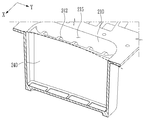
한편, 본 발명의 일실시예에서 셀스택(100)은 상기 제1방향(X) 양단부에 각각 배치되어 외측면이 상기 엔드면에 해당되는 한 쌍의 엔드서포트(120)를 더 포함하며, 상기 엔드벽(240)은 마주하는 상기 엔드면으로부터 중앙부가 멀어지도록 외측으로 휘어지고, 상기 엔드면은 마주하는 상기 엔드벽(240)으로부터 중앙부가 멀어지도록 내측으로 만입되어 스웰링공간이 형성될 수 있다.On the other hand, in one embodiment of the present invention, the
도 2 및 9와 같이 본 발명의 일실시예에 따른 배터리의 대형 모듈(1000)에서 상기 셀스택(100)은 상기 제1방향(X)의 상기 양단부에 각각 배치되어 외측면이 상기 엔드면에 해당하는 한 쌍의 엔드서포트(120)를 더 포함할 수 있다.2 and 9, in the
본 발명의 일실시예에서, 복수의 단위셀(110)은 절연부재(112)에 의해 적어도 측면이 감싸진 형태로 마련되고, 엔드서포트(120)는 셀스택(100)에서 제1방향(X) 양단에서 각각 절연부재(112)에 내측면이 면착된 형태로 배치될 수 있다. 다만, 절연부재(112) 및 엔드서포트(120)의 배치관계는 반드시 이에 한정되는 것은 아니다. 도 11에는 엔드서포트(120)의 엔드면이 도시되어 있다.In one embodiment of the present invention, the plurality of
엔드서포트(120)는 셀스택(100)에서 제1방향(X) 양단에 배치되어 외측면이 엔드면에 해당될 수 있다. 엔드서포트(120)는 엔드벽(240)과 최외곽셀 사이에서 충격을 흡수하는 역할을 수행하며, 엔드벽(240)의 가압력을 최외곽셀에 균일하게 전달하는 역할을 수행할 수 있다. The
최외곽셀이란, 셀스택(100)을 구성하는 복수의 단위셀(110) 중 제1방향(X)으로 최외곽에 위치되는 단위셀(110)을 의미하며, 본 발명의 일실시예에서 최외곽셀은 복수의 단위셀(110) 중 제1방향(X) 양단에 각각 위치된다.The outermost cell means a
엔드벽(240)이 휘어진 형상을 가지는 등 면 전체로서 상기 엔드서포트(120)를 가압하지 않더라도 상기 엔드서포트(120)는 바람직하게는 절연부재(112) 및 최외곽셀의 외측면을 면 전체로서 가압할 수 있다.Even if the
한편, 도 9에는 중앙부가 엔드면으로부터 멀어지도록 휘어진 엔드벽(240)의 단면이 도시되어 있으며, 도 10에는 휘어진 엔드벽(240)에서 셀스택(100)의 엔드면을 바라보는 내측면이 도시되어 있다.On the other hand, Figure 9 shows a cross-section of the
엔드벽(240)은 마주하는 상기 엔드면으로부터 중앙부가 멀어지도록 외측으로 휘어짐으로써 상기 엔드면과의 사이에 스웰링공간이 형성될 수 있다. 엔드벽(240)은 엔드면으로부터 중앙부가 멀어지도록 휘어진 형상으로 성형될 수 있다.The
엔드벽(240)은 제2방향(Y) 및 높이방향을 기준으로 중앙부만이 오목하게 만입될 수도 있으나, 도 9에 도시된 것처럼 단면이 만곡된 형상이 되도록 휘어진 형태로 마련될 수 있다.The
엔드벽(240)이 휘어진 형상을 가짐으로써 셀스택(100)의 엔드면 사이에 적어도 중앙부에는 공간이 형성되며, 해당 공간은 본 발명의 일실시예에서 스웰링공간에 해당된다.Since the
셀스택(100)을 구성하는 단위셀(110)은 사용에 따른 내구 진행이나 주변 상황에 따라 내부의 전극조립체로부터 기체가 발생하여 팽창하는 스웰링 현상이 발생될 수 있으며, 상기 스웰링에 적절히 대처할 수 있는 구조를 구현하는 것은 특히 복수의 단위셀(110)이 정렬된 구조에서는 중요하다.The
스웰링 현상이 발생되면 단위셀(110)은 구조적 특성상 제1방향(X)에 위치되는 측면상의 중앙부 팽창량이 크며, 이에 따라 본 발명의 일실시예는 셀스택(100)의 스웰링 현상 발생 시 상기 스웰링에 따른 셀스택(100)의 부피 팽창을 수용할 수 있도록 엔드벽(240)과 엔드면 사이에 스웰링공간을 형성하게 된다.When the swelling occurs, the
한편, 앞서 설명된 바와 같이 셀스택(100)은 에너지밀도 등과 같은 효율성 측면에서 제1방향(X)으로의 가압이 요구되는데, 본 발명의 일실시예는 엔드면을 가압하는 엔드벽(240)이 중앙부가 만곡하게 휘어지더라도, 적어도 양단부측은 엔드면의 가압상태를 유지하므로 셀스택(100)의 운용에 유리하다.On the other hand, as described above, the
한편, 도 11에 도시된 바와 같이 엔드서포트(120)의 엔드면은 마주하는 상기 엔드벽(240)으로부터 중앙부가 멀어지도록 내측으로 만입될 수 있다. 즉, 엔드벽(240)은 엔드면의 중앙부가 만입된 형상을 가질 수 있다.On the other hand, as shown in Figure 11, the end surface of the
엔드서포트(120)의 외측면에 해당하는 엔드면은 휘어진 형상의 엔드벽(240)과 유사하게 엔드벽(240)과의 사이에 적어도 중앙부는 공간이 형성되도록 중앙부가 만입된 형상을 가질 수 있고, 이에 따라 엔드서포트(120)와 엔드벽(240) 사이에는 적어도 중앙부에 스웰링공간이 형성될 수 있다.The end surface corresponding to the outer surface of the
한편, 본 발명의 일실시예에서 상기 엔드벽(240)은, 외측면에서 상기 엔드벽(240)의 높이방향으로 연장되고 상기 제2방향(Y)으로 상호 이격 배치되는 복수의 제1리브(242)를 포함하고, 상기 엔드서포트(120)는, 상기 엔드면에서 격자 형태를 이루도록 상기 제2방향(Y) 및 상기 엔드서포트(120)의 높이방향으로 이격 배치되는 복수의 제2리브(122)를 포함할 수 있다.On the other hand, in one embodiment of the present invention, the
도 2 및 9에 도시된 바와 같이 엔드벽(240)에는 본 발명의 일실시예에 따라 복수의 제1리브(242)가 형성될 수 있다. 구체적으로, 상기 엔드벽(240)은, 상기 제1방향(X)을 기준으로 외측면에 복수의 제1리브(242)를 포함할 수 있다.2 and 9, a plurality of
엔드벽(240)은 셀스택(100)의 엔드면을 가압하면서도 외부로부터의 충격에 강건할 필요가 있고, 나아가 스웰링공간이 형성되더라도 상기 스웰링공간의 수용범위를 넘어서 셀스택(100)의 길이변화가 발생되는 경우에도 상기 엔드벽(240)은 파손이 방지될 수 있는 기계적 강도가 요구된다.The
이에 따라, 본 발명의 일실시예는 도 2 및 7에 도시된 것처럼 엔드벽(240)의 외측면, 즉 외벽(210)을 바라보는 일면 또는 셀스택(100)의 반대측 면에 복수의 제1리브(242)가 마련될 수 있다.Accordingly, according to an embodiment of the present invention, as shown in FIGS. 2 and 7, a plurality of first surfaces are formed on the outer surface of the
제1리브(242)는 셀스택(100)의 보호를 위해 엔드벽(240)의 외측면에 형성된다. 엔드벽(240)의 외측면은 엔드서포트(120)의 반대측을 향하는 면을 의미한다. 제1리브(242)는 별도로 제조되어 엔드벽(240)에 결합되는 형태일 수 있으나, 바람직하게는 엔드벽(240)에 주조 공정을 통해 일체로 형성될 수 있다.The
도 2 및 9에 도시된 것처럼 상기 복수의 제1리브(242)는 상기 엔드벽(240)의 높이방향으로 연장되고 상기 제2방향(Y)으로 상호 이격 배치될 수 있다.2 and 9, the plurality of
제1리브(242)는 엔드벽(240)의 높이방향으로 연장된 형태로 마련될 수 있다. 제1리브(242)는 엔드벽(240)의 강도를 효과적으로 향상시키고, 상부몰드 및 하부몰드를 이용한 주조 공정에서 엔드벽(240)과 일체로 형성되는 데에 유리하다.The
나아가, 상기 제1리브(242)는 복수로 마련되어 제2방향(Y)을 따라 이격 배치됨으로써 엔드벽(240) 전체에 대해 균일하고 안정적인 강도 향상을 구현한다. 도 9에는 제2방향(Y)을 따라 이격 배치된 복수의 제1리브(242)의 단면이 도시되어 있다.Furthermore, a plurality of the
한편, 도 11에는 엔드면에 복수의 제2리브(122)가 형성되는 엔드서포트(120)가 도시되어 있다. 엔드서포트(120)는 스웰링 발생 시 복수의 단위셀(110)에서 전달되는 스웰링포스가 작용하게 되는 바, 스웰링 현상에 따른 단위셀(110)들의 팽창에 대응하면서도 변형 및 파손에 강건할 필요가 있다.Meanwhile, FIG. 11 shows an
이에 따라, 제2리브(122)는 엔드서포트(120)의 엔드면에 형성되어 상기 엔드서포트(120)의 강성을 향상시킨다. 즉, 엔드서포트(120)의 내측면, 즉 엔드면의 반대측 면은 셀스택(100)의 최외곽셀의 외측면 또는 절연부재(112)와 면착되어 균일한 가압 능력을 확보하면서, 엔드서포트(120)의 엔드면에는 제2리브(122)가 형성된다.Accordingly, the
또한, 도 11에 도시된 바와 같이, 본 발명의 일실시예에서 상기 제2리브(122)는 격자 형태를 이루도록 상기 제2방향(Y) 및 상기 엔드서포트(120)의 높이방향으로 이격 배치될 수 있다.In addition, as shown in FIG. 11, in one embodiment of the present invention, the
본 발명의 일실시예에서 제2리브(122)는 연장방향을 따라 엔드면의 대략 전체를 가로지르도록 형성될 수 있고, 복수의 제2리브(122) 중 일부는 제2방향(Y)으로, 나머지는 엔드서포트(120)의 높이방향으로 연장되어 상호 격자 형태를 이루도록 배치될 수 있다.In one embodiment of the present invention, the
달리 말하면, 엔드서포트(120)는 엔드면에 대략 사각 형태의 홈이 격자 형태로 배치될 수 있으며, 제2리브(122)는 별개로 제작되어 엔드서포트(120)의 엔드면에 결합되거나 엔드서포트(120)의 제조 시 일체로 형성될 수 있다.In other words, the
한편, 본 발명의 일실시예에서 어느 하나의 삽입부(220)의 고정벽(250)은 분리벽(230), 한 쌍의 엔드벽(240) 및 외벽(210) 일부를 포함하여 정의될 수 있으며, 상기 분리벽(230) 및 엔드벽(240)은 주조 공정 등을 통해 일체로 형성될 수 있다.Meanwhile, in one embodiment of the present invention, the fixed
또한, 도 2에 도시된 바와 같이 본 발명의 일실시예는 고정벽(250)의 4면 중 1면이 분리벽(230)에 해당하고, 다른 2면이 각각 엔드벽(240)에 해당하며, 나머지 1면은 모듈하우징(200)의 외벽(210)으로 구성될 수 있다.In addition, as shown in FIG. 2, in one embodiment of the present invention, one of the four surfaces of the fixed
본 발명의 일실시예에 따른 배터리의 대형 모듈(1000)에서, 상기 모듈하우징(200)은 주조 공정을 통해 상기 엔드벽(240), 상기 분리벽(230) 및 상기 외벽(210)이 바닥면(260)과 일체로 형성될 수 있다.In a
즉, 본 발명의 일실시예는 상기 엔드벽(240)과 분리벽(230)이 모듈하우징(200)에 일체로 형성될 수 있으며, 주조 공정을 위한 몰드의 제작 시 상기 몰드에 상기 엔드벽(240)과 분리벽(230)의 음각이 일체로 형성될 수 있다.That is, according to an embodiment of the present invention, the
또한, 본 발명의 일실시예에서는 상기 엔드벽(240)과 분리벽(230)이 상기 모듈하우징(200)의 외벽(210)과도 일체로 형성될 수 있다. 이 경우, 모듈하우징(200)은 외벽(210), 분리벽(230), 엔드벽(240) 및 바닥면(260)이 모두 일체로 제작될 수 있다.In addition, in one embodiment of the present invention, the
한편, 도 12에는 본 발명의 일실시예에 따른 모듈하우징(200)의 단면이 도시되어 있으며, 모듈하우징(200)의 바닥면(260) 아래에 냉각수가 유동하는 유동공간(310)을 가지는 냉각채널(300)이 형성된 모습이 도시되어 있다. 도 13에는 상기 냉각채널(300)을 아래에서 바라본 모습이 도시되어 있다.Meanwhile, FIG. 12 shows a cross-section of a
도 12와 같이, 본 발명의 일실시예에 따른 배터리의 대형 모듈(1000)에서 상기 모듈하우징(200)은 바닥면(260)의 아래에 냉각수가 유동하는 냉각채널(300)이 형성될 수 있다. 또한, 바닥면(260)의 하면에는 도 13에 도시된 바와 같이 냉각수의 유동방향으로 연장되어 냉각수의 유동을 가이드하는 가이드리브(350)가 복수개로 마련될 수 있다.As shown in FIG. 12, in the
냉각채널(300)의 유동공간(310)은 바닥면(260) 전체에 걸쳐 형성되거나 삽입부(220)가 형성되는 모듈하우징(200)의 내부공간 단면적에 대응하도록 형성될 수도 있다. 예컨대, 제1충격흡수공간(215)의 하부에는 냉각채널(300)의 유동공간(310)이 존재하지 않도록 설계될 수도 있다. 냉각채널(300)의 내부에는 냉각수가 유동하는데, 공기 등과 같이 냉각수를 대신하는 다양한 냉매가 이용될 수도 있다.The
셀스택(100)을 구성하는 단위셀(110)은 방전 시 열을 발산하는 발열체에 해당하며, 그 온도가 지나치게 상승하는 경우 스웰링 현상이 유도되거나 급격한 화학반응을 통해 열이 비약적으로 상승하여 화재 등이 발생하는 열폭주 현상이 발생될 수 있다.The
또한, 본 발명의 일실시예와 같이 복수의 단위셀(110)이 정렬된 셀스택(100)이 이용되는 경우, 어느 하나의 단위셀(110)에서 상기 열폭주 현상이 발생되면 주변의 다른 단위셀(110)에도 영향을 미치는 열폭주 확산 현상이 발생될 수도 있다.In addition, when a
위와 같이 복수의 단위셀(110)이 배치되는 경우, 셀스택(100)에서 발생되는 열을 적절히 냉각시키는 것은 중요하며, 이에 따라 본 발명의 일실시예에 따른 배터리의 대형 모듈(1000)은 모듈하우징(200)의 바닥면(260) 아래에 냉각채널(300)을 형성하여 복수의 셀스택(100) 전체의 냉각을 효율적으로 구현한다.When a plurality of
또한, 본 발명의 일실시예는 모듈하우징(200) 내부가 아니라 모듈하우징(200)의 바닥면(260) 아래, 즉 모듈하우징(200)의 내부공간과 구획된 공간에 냉각채널(300)을 형성함으로써 냉각채널(300)의 보수 및 관리를 보다 용이하게 진행할 수 있다. In addition, an embodiment of the present invention is not the inside of the
한편, 본 발명의 일실시예에 따른 배터리의 대형 모듈(1000)에서 상기 냉각채널(300)의 측벽(320)은 상기 바닥면(260)으로부터 하방으로 돌출되며, 상기 바닥면(260)의 테두리를 따라 연장되어 상기 바닥면(260)을 둘러싸도록 형성되고, 채널커버(330)가 측벽(320) 하단에 결합되어 상기 냉각채널(300)을 밀폐시킬 수 있다.On the other hand, the
또한, 상기 냉각채널(300)의 측벽(320)은 주조 공정을 통해 상기 모듈하우징(200)의 바닥면(260)에 일체로 형성될 수 있으며, 채널커버(330)는 냉각채널(300)의 측벽(320)에 용접 결합될 수 있다.In addition, the
도 12에는 냉각채널(300)의 측벽(320)이 모듈하우징(200)의 바닥면(260) 테두리를 따라 연장되어 상기 바닥면(260)을 둘러싸도록 마련되고, 바닥면(260)으로부터 하방으로 돌출 형성된 모습이 도시되어 있다.12, the
특히, 본 발명의 일실시예는 냉각채널(300)의 측벽(320)이 모듈하우징(200)의 바닥면(260)과 주조 공정을 통해 일체로 형성되므로, 상호간의 결합부위가 존재하지 않으며, 이에 따라 모듈하우징(200) 내부로 의도치 않게 냉각수가 누수되는 상황이 미연에 방지될 수 있다. In particular, in one embodiment of the present invention, since the
냉각채널(300)의 측벽(320)에는 냉각채널(300)을 밀폐하는 채널커버(330)가 용접 등의 방식으로 결합될 수 있으며, 바람직하게는 상기 측벽(320)의 하단에 채널커버(330)의 테두리가 결합될 수 있다.A
결합방식은 다양할 수 있으나 냉각수의 누수 방지를 위해 가스켓을 구비하거나 용접 결합될 수 있으며, 도 13에는 채널커버(330)가 제거된 상태에서 상기 냉각채널(300)을 아래에서 바라본 모습이 도시되어 있다.The coupling method may be various, but may be provided with a gasket or welded to prevent leakage of cooling water, and FIG. 13 shows a view of the
모듈하우징(200)의 외벽(210), 바닥면(260) 및 냉각채널(300)의 측벽(320)이 모두 주조 공정을 통해 일체로 형성되어 누수 가능 부위가 존재하지 않게 되고, 나아가 냉각채널(300)은 모듈하우징(200)의 바닥면(260) 하부, 즉 모듈하우징(200) 내부공간의 외부에 마련되므로, 냉각채널(300)에서 의도치 않게 발생되는 냉각수의 누수가 있더라도 상기 냉각수가 셀스택(100)이 존재하는 모듈하우징(200)의 내부공간으로 침범하는 상황을 방지할 수 있다.The
결국, 본 발명의 일실시예는 복수의 셀스택(100)이 삽입되어 조립 공정 및 구성부품을 단순화하면서도 높은 요구전력을 효과적으로 충족시킴과 동시에, 냉각채널(300)을 통해 복수의 셀스택(100)을 효과적으로 냉각시키고, 나아가 냉각채널(300)에서 발생될 수 있는 냉각수의 누수 현상에서 상기 복수의 셀스택(100)을 효과적으로 보호할 수 있다.After all, one embodiment of the present invention is a plurality of
본 발명은 특정한 실시예에 관련하여 도시하고 설명하였지만, 이하의 특허청구범위에 의해 제공되는 본 발명의 기술적 사상을 벗어나지 않는 한도 내에서, 본 발명이 다양하게 개량 및 변화될 수 있다는 것은 당 업계에서 통상의 지식을 가진 자에게 있어서 자명할 것이다.Although the present invention has been illustrated and described in relation to specific embodiments, it is understood in the art that the present invention can be variously improved and changed within the limits that do not depart from the technical spirit of the present invention provided by the following claims. It will be obvious to those of ordinary skill.
100 : 셀스택
110 : 단위셀
112 : 절연부재
120 : 엔드서포트
122 : 제2리브
150 : 단자부
151 : 제1단자
152 : 제2단자
172 : 스택버스바
174 : 연결버스바
176 : 단자버스바
178 : 크로스버스바
200 : 모듈하우징
210 : 외벽
211 : 제1벽
212 : 제2벽
215 : 제1충격흡수공간
216 : 제2충격흡수공간
220 : 삽입부
230 : 분리벽
240 : 엔드벽
242 : 제1리브
250 : 고정벽
260 : 모듈하우징의 바닥면
300 : 냉각채널
310 : 유동공간
320 : 냉각채널의 측벽
330 : 채널커버
350 : 가이드리브
400 : 결합부
500 : 커넥터
510 : 숫커넥터
512 : 제1돌기
514 : 제2돌기
515 : 전류연결부
517 : 신호연결부
519, 539 : 연통홀
520 : 실링벽
530 : 암커넥터
532 : 제1수용부
534 : 제2수용부
535 : 전류수용부
537 : 신호수용부
550 : 가이드돌기
555 : 체결홈
570 : 가이드홈
575 : 체결공
580 : 체결부재
1000 : 배터리의 대형 모듈100: cell stack 110: unit cell
112: insulating member 120: end support
122: second rib 150: terminal portion
151: first terminal 152: second terminal
172: Stack bus bar 174: Connected bus bar
176: Terminal bus bar 178: Cross bus bar
200: module housing 210: outer wall
211: 1st wall 212: 2nd wall
215: first shock absorption space 216: second shock absorption space
220: insertion section 230: separation wall
240: end wall 242: first rib
250: fixed wall 260: the bottom surface of the module housing
300: cooling channel 310: flow space
320: side wall of the cooling channel 330: channel cover
350: guide rib 400: coupling portion
500: connector 510: male connector
512: first projection 514: second projection
515: current connection 517: signal connection
519, 539: communication hole 520: sealing wall
530: female connector 532: first receiving portion
534: second receiving portion 535: current receiving portion
537: signal receiving unit 550: guide projection
555: fastening groove 570: guide groove
575: fastener 580: fastener
1000: large module of battery
Claims (19)
상기 셀스택이 삽입되는 삽입부가 복수개로 마련되는 모듈하우징;을 포함하며,
상기 삽입부는, 상기 셀스택을 둘러싸며 적어도 일부가 상기 셀스택과 접촉되는 고정벽;을 포함하고,
상기 모듈하우징에 구비되고, 이웃하는 모듈하우징과 결합되는 결합부;를 더 포함하며,
상기 결합부는, 상기 모듈하우징 및 상기 이웃하는 모듈하우징을 전기적 및 신호적으로 연결하는 커넥터;를 포함하는 배터리의 대형 모듈.A cell stack in which a plurality of unit cells are arranged in a first direction and includes an insulating member surrounding the plurality of unit cells; And
It includes; a module housing in which a plurality of inserts into which the cell stack is inserted are provided.
The insertion portion, surrounding the cell stack and at least a portion of the fixed wall in contact with the cell stack; includes,
It is provided in the module housing, the coupling portion coupled to the adjacent module housing; further includes,
The coupling unit, a connector for electrically and signally connecting the module housing and the neighboring module housing; a large module of a battery comprising a.
상기 커넥터는,
상기 모듈하우징의 내부공간을 둘러싸는 외벽 중 상기 제1방향에 수직한 제2방향에 위치되는 제1벽에 구비되는 숫커넥터; 및
상기 외벽 중 상기 제1벽의 반대측에 위치되는 제2벽에 구비되어 상기 이웃하는 모듈하우징의 숫커넥터와 결합되는 암커넥터;를 포함하는 배터리의 대형 모듈.According to claim 1,
The connector,
A male connector provided on a first wall positioned in a second direction perpendicular to the first direction among outer walls surrounding the inner space of the module housing; And
A large module of a battery comprising a female connector provided on a second wall of the outer wall located on the opposite side of the first wall to be coupled with the male connector of the neighboring module housing.
상기 숫커넥터는, 상기 제2방향으로 돌출되고 상기 모듈하우징 내부에서 셀스택과 전기적으로 연결되는 전류연결부;를 포함하고,
상기 암커넥터는 상기 제2방향으로 만입되고 상기 이웃하는 모듈하우징의 상기 숫커넥터의 상기 전류연결부가 삽입되는 전류수용부;를 포함하는 배터리의 대형 모듈.According to claim 2,
The male connector protrudes in the second direction and includes a current connection part electrically connected to a cell stack inside the module housing.
The female connector is embedded in the second direction and a current receiving portion into which the current connecting portion of the male connector of the neighboring module housing is inserted.
상기 숫커넥터는, 상기 제2방향으로 돌출되고 상기 셀스택의 관리제어신호를 전달하는 신호연결부;를 더 포함하고,
상기 암커넥터는, 상기 제2방향으로 만입되고 상기 이웃하는 모듈하우징의 상기 숫커넥터의 상기 신호연결부가 삽입되는 신호수용부;를 더 포함하는 배터리의 대형 모듈.According to claim 3,
The male connector further includes a signal connection unit protruding in the second direction and transmitting a management control signal of the cell stack.
The female connector, a large module of the battery further comprising; a signal receiving portion is inserted in the second direction and the signal connection portion of the male connector of the neighboring module housing is inserted.
상기 커넥터는 중앙에 상기 모듈하우징의 내부와 외부가 연통되는 연통홀이 형성되는 배터리의 대형 모듈.According to claim 2,
The connector is a large module of a battery in which a communication hole communicating with the inside and the outside of the module housing is formed in the center.
상기 결합부는,
상기 제1벽에서 상기 숫커넥터의 측부에 위치되며, 상기 제2방향으로 돌출되는 가이드돌기; 및
상기 제2벽에서 상기 암커넥터의 측부에 위치되며, 상기 이웃하는 모듈하우징의 가이드돌기가 삽입되는 가이드홈;을 더 포함하는 배터리의 대형 모듈.According to claim 2,
The coupling portion,
A guide protrusion located on the side of the male connector on the first wall and protruding in the second direction; And
The second wall is located on the side of the female connector, a guide groove into which the guide projection of the neighboring module housing is inserted; further comprising a large module of the battery.
상기 가이드돌기에는 상기 외벽의 높이방향으로 체결홈이 형성되고,
상기 가이드홈의 측면에는 상기 체결홈과 대응되는 위치에 체결공이 형성되며,
상기 가이드돌기는 상기 체결공을 관통하여 상기 체결홈에 삽입되는 체결부재를 통해 상기 가이드홈과 결합되는 배터리의 대형 모듈.The method of claim 6,
A fastening groove is formed in the guide projection in the height direction of the outer wall,
On the side surface of the guide groove, a fastening hole is formed at a position corresponding to the fastening groove,
The guide projection is a large module of the battery that is coupled to the guide groove through a fastening member that is inserted into the fastening groove through the fastening hole.
상기 숫커넥터는, 상기 전류연결부 및 상기 신호연결부를 둘러싸고, 상기 제2방향으로 돌출되며, 단부에 실러가 구비되는 실링벽;을 더 포함하는 배터리의 대형 모듈.According to claim 4,
The male connector surrounds the current connection unit and the signal connection unit, and protrudes in the second direction, and further includes a sealing wall provided with a sealer at an end thereof.
상기 삽입부는 상기 제2방향을 따라 제1열 및 제2열을 이루도록 배치되고,
상기 제1열에 포함되는 셀스택들은 상기 제2열에 포함되는 셀스택들과 서로 전기적으로 분리되는 배터리의 대형 모듈.According to claim 3,
The insertion portion is arranged to form a first row and a second row along the second direction,
The cell stacks included in the first row are large modules of a battery that are electrically separated from the cell stacks included in the second row.
상기 셀스택에서 상기 복수의 단위셀을 전기적으로 연결하는 스택버스바;
상기 제1열 또는 상기 제2열에서 상기 제2방향으로 이웃하는 2개의 셀스택을 전기적으로 연결하는 연결버스바; 및
상기 셀스택으로부터 인출되며, 상기 전류연결부 또는 상기 전류수용부와 연결되는 단자버스바;를 포함하는 배터리의 대형 모듈.The method of claim 9,
A stack bus bar that electrically connects the plurality of unit cells in the cell stack;
A connection bus bar for electrically connecting two cell stacks neighboring in the second direction in the first row or the second row; And
A large module of a battery including; a terminal bus bar drawn out from the cell stack and connected to the current connecting portion or the current receiving portion.
상기 전류연결부는, 상기 제1열에 포함되는 셀스택들과 전기적으로 연결되는 제1돌기; 및 상기 제2열에 포함되는 셀스택들과 전기적으로 연결되는 제2돌기;를 포함하고,
상기 전류수용부는, 상기 제1열에 포함되는 셀스택들과 전기적으로 연결되며 상기 이웃하는 모듈하우징의 상기 제1돌기와 결합되는 제1수용부; 및 상기 제2열에 포함되는 셀스택들과 전기적으로 연결되며 상기 이웃하는 모듈하우징의 상기 제2돌기와 결합되는 제2수용부;을 포함하는 배터리의 대형 모듈.The method of claim 10,
The current connection unit includes: a first protrusion electrically connected to cell stacks included in the first row; And a second protrusion electrically connected to the cell stacks included in the second row.
The current accommodating part may include: a first accommodating part electrically connected to cell stacks included in the first row and coupled to the first protrusion of the neighboring module housing; And a second accommodating part electrically connected to the cell stacks included in the second row and coupled to the second protrusion of the neighboring module housing.
상기 셀스택에서 일단부의 단위셀에는 상기 단자버스바가 연결되고, 타단부의 단위셀에는 상기 연결버스바가 연결되며,
상기 셀스택은 상기 일단부가 상기 제1열 및 상기 제2열 사이를 바라보도록 배치되어, 상기 단자버스바가 상기 제1열 및 상기 제2열 사이로 인출되는 배터리의 대형 모듈.The method of claim 11,
In the cell stack, the terminal bus bar is connected to the unit cell of one end, and the connection bus bar is connected to the unit cell of the other end,
The cell stack is a large module of a battery in which one end is disposed to face between the first row and the second row, and the terminal bus bar is drawn between the first row and the second row.
상기 제1열의 셀스택들로부터 인출되는 단자버스바들과 상기 제2열의 셀스택들로부터 인출되는 단자버스바들은 상기 제2방향을 따라 서로 교번하여 배치되는 배터리의 대형 모듈.The method of claim 12,
A large module of a battery in which terminal bus bars drawn out from the cell stacks in the first row and terminal bus bars drawn out from the cell stacks in the second row are alternately arranged along the second direction.
상기 고정벽은,
상기 모듈하우징의 외벽으로 둘러싸인 내부공간을 상기 제1방향으로 가로지르며, 상기 셀스택의 사이드면에 접촉되는 분리벽; 및
상기 제1방향 양측에 배치되어 상기 셀스택의 상기 제1방향 양측의 엔드면을 각각 가압하는 엔드벽;을 포함하는 배터리의 대형 모듈.According to claim 1,
The fixed wall,
A separation wall that traverses the inner space surrounded by the outer wall of the module housing in the first direction and contacts the side surface of the cell stack; And
Large modules of a battery comprising; end walls disposed on both sides of the first direction to press the end faces of the first and second sides of the cell stack, respectively.
일면이 상기 모듈하우징의 상기 외벽을 마주보도록 배치되는 엔드벽은 상기 제1방향을 따라 상기 외벽으로부터 이격되어 상기 외벽과의 사이에 제1충격흡수공간이 형성되는 배터리의 대형 모듈.The method of claim 14,
A large-sized module of a battery in which an end wall having one surface facing the outer wall of the module housing is spaced apart from the outer wall along the first direction to form a first shock absorbing space between the outer wall.
상기 제1방향을 따라 이웃하는 2개의 삽입부는 상기 제1방향으로 마주하는 일면에 배치되는 엔드벽이 서로 이격되어 그 사이에 제2충격흡수공간이 형성되고,
상기 셀스택으로부터 인출되는 단자버스바는 상기 제2충격흡수공간으로 인출되는 배터리의 대형 모듈.The method of claim 15,
Two adjacent insertion portions along the first direction are end walls disposed on one surface facing the first direction spaced apart from each other to form a second shock absorption space therebetween,
The terminal bus bar drawn out from the cell stack is a large module of a battery drawn out into the second shock absorption space.
상기 셀스택은, 상기 제1방향 양단부에 각각 배치되어 외측면이 상기 엔드면에 해당되는 한 쌍의 엔드서포트;를 더 포함하며,
상기 엔드벽은 마주하는 상기 엔드면으로부터 중앙부가 멀어지도록 외측으로 휘어지고, 상기 엔드면은 마주하는 상기 엔드벽으로부터 중앙부가 멀어지도록 내측으로 만입되어 스웰링공간이 형성되는 배터리의 대형 모듈.The method of claim 16,
The cell stack further includes a pair of end supports disposed on both ends of the first direction and the outer surface corresponding to the end surface.
The end wall is bent outward so that the center portion is away from the opposing end surface, and the end surface is inwardly indented so that the center portion is away from the opposing end wall to form a swelling space.
상기 엔드벽은, 외측면에서 상기 엔드벽의 높이방향으로 연장되고 상기 제2방향으로 상호 이격 배치되는 복수의 제1리브;를 포함하고,
상기 엔드서포트는, 상기 엔드면에서 격자 형태를 이루도록 상기 제2방향 및 상기 엔드서포트의 높이방향으로 이격 배치되는 복수의 제2리브;를 포함하는 배터리의 대형 모듈.The method of claim 17,
The end wall includes a plurality of first ribs extending from the outer surface in the height direction of the end wall and spaced apart from each other in the second direction.
The end support, a large module of the battery comprising a; a plurality of second ribs are spaced apart in the height direction of the second direction and the end support so as to form a grid on the end surface.
상기 모듈하우징은 바닥면의 아래에 냉각수가 유동하는 냉각채널이 형성되는 배터리의 대형 모듈.According to claim 1,
The module housing is a large module of a battery in which a cooling channel through which cooling water flows is formed under the bottom surface.
Priority Applications (7)
| Application Number | Priority Date | Filing Date | Title |
|---|---|---|---|
| KR1020180125548A KR102640328B1 (en) | 2018-10-19 | 2018-10-19 | Large module of battery |
| PL19203917.0T PL3641008T3 (en) | 2018-10-19 | 2019-10-17 | Battery module |
| EP19203917.0A EP3641008B1 (en) | 2018-10-19 | 2019-10-17 | Battery module |
| CN201921752395.5U CN211350716U (en) | 2018-10-19 | 2019-10-17 | Battery module |
| US16/656,099 US11616265B2 (en) | 2018-10-19 | 2019-10-17 | Battery module |
| CN201910989914.8A CN111081928B (en) | 2018-10-19 | 2019-10-17 | Battery module |
| HUE19203917A HUE061582T2 (en) | 2018-10-19 | 2019-10-17 | Battery module |
Applications Claiming Priority (1)
| Application Number | Priority Date | Filing Date | Title |
|---|---|---|---|
| KR1020180125548A KR102640328B1 (en) | 2018-10-19 | 2018-10-19 | Large module of battery |
Publications (2)
| Publication Number | Publication Date |
|---|---|
| KR20200044577A true KR20200044577A (en) | 2020-04-29 |
| KR102640328B1 KR102640328B1 (en) | 2024-02-22 |
Family
ID=68296011
Family Applications (1)
| Application Number | Title | Priority Date | Filing Date |
|---|---|---|---|
| KR1020180125548A KR102640328B1 (en) | 2018-10-19 | 2018-10-19 | Large module of battery |
Country Status (6)
| Country | Link |
|---|---|
| US (1) | US11616265B2 (en) |
| EP (1) | EP3641008B1 (en) |
| KR (1) | KR102640328B1 (en) |
| CN (2) | CN111081928B (en) |
| HU (1) | HUE061582T2 (en) |
| PL (1) | PL3641008T3 (en) |
Families Citing this family (4)
| Publication number | Priority date | Publication date | Assignee | Title |
|---|---|---|---|---|
| KR20210138998A (en) | 2020-05-13 | 2021-11-22 | 삼성에스디아이 주식회사 | Battery pack |
| CN114665183A (en) * | 2020-12-22 | 2022-06-24 | 比亚迪股份有限公司 | Battery module, battery package and vehicle |
| CN113097638B (en) * | 2021-03-31 | 2023-02-03 | 东莞新能安科技有限公司 | Battery module, battery pack, and electric device |
| CN114156435A (en) * | 2021-12-08 | 2022-03-08 | 霍艳增 | Novel electrode connecting sheet of gel lithium battery |
Citations (3)
| Publication number | Priority date | Publication date | Assignee | Title |
|---|---|---|---|---|
| US20070054561A1 (en) * | 2005-09-02 | 2007-03-08 | Gutman Robert F | Integrated Module Connection For HEV Battery |
| US20120177970A1 (en) * | 2011-01-10 | 2012-07-12 | Cobasys, Llc | Flexible battery module for prismatic cells |
| JP2017037754A (en) * | 2015-08-07 | 2017-02-16 | 株式会社デンソー | Battery pack |
Family Cites Families (80)
| Publication number | Priority date | Publication date | Assignee | Title |
|---|---|---|---|---|
| US6146778A (en) | 1997-07-25 | 2000-11-14 | 3M Innovative Properties Company | Solid-state energy storage module employing integrated interconnect board |
| US6255015B1 (en) | 1998-08-23 | 2001-07-03 | Ovonic Battery Company, Inc. | Monoblock battery assembly |
| JP4642179B2 (en) | 1999-10-08 | 2011-03-02 | パナソニック株式会社 | Collective secondary battery |
| JP3906706B2 (en) | 2002-02-15 | 2007-04-18 | 三菱電機株式会社 | Battery module |
| JP3891860B2 (en) | 2002-02-26 | 2007-03-14 | トヨタ自動車株式会社 | Collective battery and battery system |
| US20050255379A1 (en) | 2004-05-12 | 2005-11-17 | Michael Marchio | Battery assembly with heat sink |
| US20070087266A1 (en) | 2005-10-18 | 2007-04-19 | Debbi Bourke | Modular battery system |
| KR100889241B1 (en) | 2006-10-23 | 2009-03-17 | 주식회사 엘지화학 | Member of Connecting Electrode in Battery Module |
| JP2009087720A (en) | 2007-09-28 | 2009-04-23 | Toshiba Corp | Battery pack |
| JP5436924B2 (en) | 2009-05-08 | 2014-03-05 | 三洋電機株式会社 | Battery system |
| JP5537111B2 (en) | 2009-09-30 | 2014-07-02 | 株式会社東芝 | Secondary battery device |
| CN102117930B (en) | 2010-01-05 | 2015-09-16 | 三星Sdi株式会社 | Battery pack |
| US20110165451A1 (en) | 2010-01-05 | 2011-07-07 | Myung-Chul Kim | Battery pack |
| KR101297176B1 (en) | 2010-06-03 | 2013-08-21 | 주식회사 엘지화학 | Battery Module Having Novel Structure |
| KR101136310B1 (en) | 2010-06-07 | 2012-04-19 | 에스비리모티브 주식회사 | Battery pack |
| KR20120044853A (en) | 2010-10-28 | 2012-05-08 | 현대자동차주식회사 | Battery pack case assembly for electric vehicles using plastic composite |
| US8642206B2 (en) | 2010-11-04 | 2014-02-04 | Samsung Sdi Co., Ltd. | Battery module |
| EP2450980B1 (en) | 2010-11-04 | 2016-07-27 | Samsung SDI Co., Ltd. | Battery module |
| DE102011076981B4 (en) | 2011-06-06 | 2021-08-26 | Robert Bosch Gmbh | Battery system, motor vehicle with this battery system and method for producing operational readiness in a motor vehicle with this battery system |
| JP5549647B2 (en) | 2011-06-23 | 2014-07-16 | 三菱自動車工業株式会社 | battery pack |
| AT511668B1 (en) | 2011-06-30 | 2015-05-15 | Avl List Gmbh | RECHARGEABLE ELECTRIC BATTERY |
| US9614208B2 (en) | 2011-10-10 | 2017-04-04 | Samsung Sdi Co., Ltd. | Battery pack with degassing cover and plate thereon |
| EP2608309A1 (en) | 2011-12-21 | 2013-06-26 | Fortu Intellectual Property AG | Battery module with battery module housing and battery cells |
| KR101488411B1 (en) | 2012-01-02 | 2015-02-03 | 주식회사 엘지화학 | Battery Pack Including Connecting member, Side Supporting Member and Bottom Supporting Member |
| US20130260195A1 (en) | 2012-04-02 | 2013-10-03 | Shijin Long | Oil-cooled lithium battery module |
| KR101413488B1 (en) | 2012-04-06 | 2014-07-02 | 인지컨트롤스 주식회사 | Refrigerant manifold for cell |
| JP6224321B2 (en) | 2013-01-11 | 2017-11-01 | フタバ産業株式会社 | Battery assembly restraint, battery assembly restraint member, battery |
| CN104904033B (en) * | 2013-04-15 | 2018-03-09 | 株式会社Lg 化学 | Battery module with novel structure and the battery pack including the battery module |
| EP2991131B1 (en) | 2013-05-15 | 2017-12-20 | Lg Chem, Ltd. | Battery module assembly |
| JP6257951B2 (en) | 2013-08-09 | 2018-01-10 | 株式会社東芝 | Battery module |
| KR102172846B1 (en) | 2014-02-10 | 2020-11-02 | 삼성에스디아이 주식회사 | Battery pack |
| KR101584295B1 (en) | 2014-07-03 | 2016-01-25 | 인셀(주) | Battery System Having Rack Structure |
| KR101778666B1 (en) | 2014-09-29 | 2017-09-14 | 주식회사 엘지화학 | Energy Storage Apparatus of Combined Cooling Manner |
| DE102014115561A1 (en) | 2014-10-27 | 2016-04-28 | Dr. Ing. H.C. F. Porsche Aktiengesellschaft | Battery casing |
| CN104617244B (en) | 2014-12-05 | 2017-02-22 | 超威电源有限公司 | Electric-car storage-battery anti-shock crashproof structure |
| US9931961B2 (en) | 2015-02-11 | 2018-04-03 | Ford Global Technologies, Llc | Battery enclosure surrounded by internally reinforced cylindrical impact absorbing elements |
| US9660234B2 (en) | 2015-02-11 | 2017-05-23 | Ford Global Technologies, Llc | Battery enclosure with arc-shaped elongated impact absorbing ribs |
| KR102314041B1 (en) | 2015-03-12 | 2021-10-18 | 삼성에스디아이 주식회사 | Battery pack |
| EP3285310B1 (en) | 2015-04-16 | 2020-03-11 | Panasonic Intellectual Property Management Co., Ltd. | Assembled battery |
| CN106299176B (en) | 2015-05-26 | 2019-04-02 | 深圳腾势新能源汽车有限公司 | Power battery case with endergonic structure |
| KR102074250B1 (en) | 2015-07-22 | 2020-02-06 | 주식회사 엘지화학 | Battery Pack with Expandable Structure |
| CN107851753B (en) | 2015-07-30 | 2020-12-22 | 三洋电机株式会社 | Power supply device and vehicle using same |
| US10418671B2 (en) | 2015-07-30 | 2019-09-17 | Sanyo Electric Co., Ltd. | Power supply device, power supply system provided with said power supply device, and separator for battery cells |
| KR102397218B1 (en) | 2015-08-27 | 2022-05-12 | 삼성에스디아이 주식회사 | Battery pack |
| KR101805650B1 (en) | 2015-08-28 | 2017-12-06 | 삼성에스디아이 주식회사 | Rechargeable battery pack |
| KR102032504B1 (en) | 2015-11-06 | 2019-11-08 | 주식회사 엘지화학 | Battery Module improved impact resistance |
| WO2017101679A1 (en) | 2015-12-16 | 2017-06-22 | 比亚迪股份有限公司 | Tray, power battery pack and electric vehicle |
| CN109075370B (en) * | 2016-01-29 | 2022-04-08 | 法拉第未来公司 | Battery cell and battery pack for vehicle energy storage system |
| JP6363645B2 (en) | 2016-03-09 | 2018-07-25 | 株式会社東芝 | Battery module, battery, storage battery, and electrical device |
| KR102235655B1 (en) | 2016-06-17 | 2021-04-01 | 에스케이이노베이션 주식회사 | Secondary battery pack |
| PT3475998T (en) * | 2016-06-22 | 2021-07-09 | Commeo Gmbh | Accumulator module |
| US11075423B2 (en) | 2016-07-07 | 2021-07-27 | Samsung Sdi Co., Ltd. | Battery submodule carrier, battery submodule, battery system and vehicle |
| EP3273500B1 (en) | 2016-07-21 | 2018-09-12 | Samsung SDI Co., Ltd. | Battery system |
| KR102073853B1 (en) | 2016-09-28 | 2020-02-05 | 주식회사 엘지화학 | Secondary battery module improved in cooling passage and frame assembly for the same |
| US10062977B2 (en) | 2016-10-14 | 2018-08-28 | Inevit Llc | Module-to-module power connector between battery modules of an energy storage system and arrangement thereof |
| JP6805724B2 (en) | 2016-10-26 | 2020-12-23 | 株式会社デンソー | Battery pack |
| EP3316340B1 (en) | 2016-10-26 | 2019-03-13 | Samsung SDI Co., Ltd. | Battery module |
| EP3316344B1 (en) | 2016-11-01 | 2018-09-26 | Samsung SDI Co., Ltd. | Battery module |
| KR20180054382A (en) | 2016-11-15 | 2018-05-24 | 엘지전자 주식회사 | Heat exchanger and Battery pack having the same |
| US11901573B2 (en) | 2016-11-15 | 2024-02-13 | American Battery Solutions, Inc. | Non-welding joinder of exterior plates of a battery module |
| CN206210887U (en) * | 2016-11-24 | 2017-05-31 | 绵阳力神动力电池系统有限公司 | Batteries of electric automobile group anti-collision protection device |
| EP3327817B1 (en) | 2016-11-29 | 2019-11-06 | Samsung SDI Co., Ltd. | Wall structure of a battery cell, battery submodule, battery module or battery system |
| CN110235274A (en) | 2016-12-05 | 2019-09-13 | 三星Sdi株式会社 | Removable battery component carrier, the battery system including removable battery component carrier and including the vehicle of battery system |
| KR20180069989A (en) | 2016-12-15 | 2018-06-26 | 현대자동차주식회사 | Battery module having cooling structure |
| DE112017006992T5 (en) | 2017-02-03 | 2019-10-17 | Gs Yuasa International Ltd. | Energy storage device |
| JP6545212B2 (en) | 2017-03-17 | 2019-07-17 | 本田技研工業株式会社 | Battery pack |
| CN206584990U (en) | 2017-03-28 | 2017-10-24 | 长城汽车股份有限公司 | Battery pack lateral plate structure, battery pack housing, battery bag and vehicle |
| JP6863062B2 (en) | 2017-05-10 | 2021-04-21 | 株式会社デンソー | Control module |
| WO2018213383A1 (en) | 2017-05-16 | 2018-11-22 | Shape Corp. | Vehicle battery tray with integrated battery retention and support features |
| CN207199697U (en) | 2017-07-14 | 2018-04-06 | 宁德时代新能源科技股份有限公司 | Battery modules |
| CN207398218U (en) | 2017-09-21 | 2018-05-22 | 宁德时代新能源科技股份有限公司 | Battery modules |
| CN107658401A (en) | 2017-09-27 | 2018-02-02 | 中聚(杭州)新能源科技有限公司 | Power battery box with end-plate-free battery modules |
| US10991924B2 (en) | 2017-10-19 | 2021-04-27 | Tiveni Mergeco, Inc. | Pressure equalization between battery module compartments of an energy storage system and external environment |
| CN207690855U (en) | 2017-10-27 | 2018-08-03 | 中信国安盟固利动力科技有限公司 | A kind of high-energy density compares module |
| KR102519443B1 (en) | 2017-12-27 | 2023-04-07 | 삼성에스디아이 주식회사 | Battery pack |
| CN207818706U (en) | 2018-02-08 | 2018-09-04 | 宁德时代新能源科技股份有限公司 | Battery pack |
| CN110323376B (en) | 2018-03-30 | 2020-09-01 | 宁德时代新能源科技股份有限公司 | End plate for battery module and battery module |
| KR102643493B1 (en) * | 2018-06-28 | 2024-03-04 | 현대자동차주식회사 | Battery system for vehicle |
| KR102373774B1 (en) | 2018-08-21 | 2022-03-14 | 에스케이온 주식회사 | Battery Module and Battery Pack including the same |
| KR102640327B1 (en) | 2018-10-19 | 2024-02-22 | 삼성에스디아이 주식회사 | Large module of battery |
-
2018
- 2018-10-19 KR KR1020180125548A patent/KR102640328B1/en active IP Right Grant
-
2019
- 2019-10-17 CN CN201910989914.8A patent/CN111081928B/en active Active
- 2019-10-17 PL PL19203917.0T patent/PL3641008T3/en unknown
- 2019-10-17 HU HUE19203917A patent/HUE061582T2/en unknown
- 2019-10-17 CN CN201921752395.5U patent/CN211350716U/en active Active
- 2019-10-17 EP EP19203917.0A patent/EP3641008B1/en active Active
- 2019-10-17 US US16/656,099 patent/US11616265B2/en active Active
Patent Citations (3)
| Publication number | Priority date | Publication date | Assignee | Title |
|---|---|---|---|---|
| US20070054561A1 (en) * | 2005-09-02 | 2007-03-08 | Gutman Robert F | Integrated Module Connection For HEV Battery |
| US20120177970A1 (en) * | 2011-01-10 | 2012-07-12 | Cobasys, Llc | Flexible battery module for prismatic cells |
| JP2017037754A (en) * | 2015-08-07 | 2017-02-16 | 株式会社デンソー | Battery pack |
Also Published As
| Publication number | Publication date |
|---|---|
| PL3641008T3 (en) | 2023-04-17 |
| CN111081928A (en) | 2020-04-28 |
| EP3641008B1 (en) | 2023-01-11 |
| HUE061582T2 (en) | 2023-07-28 |
| KR102640328B1 (en) | 2024-02-22 |
| US11616265B2 (en) | 2023-03-28 |
| EP3641008A1 (en) | 2020-04-22 |
| US20200127255A1 (en) | 2020-04-23 |
| CN211350716U (en) | 2020-08-25 |
| CN111081928B (en) | 2022-10-04 |
Similar Documents
| Publication | Publication Date | Title |
|---|---|---|
| CN211350714U (en) | Battery module | |
| CN111081959B (en) | Battery module | |
| US8748021B2 (en) | Battery module | |
| CN211350900U (en) | Battery module | |
| KR20200044577A (en) | Large module of battery | |
| US20240106063A1 (en) | Battery module | |
| CN211350713U (en) | Battery module and battery pack |
Legal Events
| Date | Code | Title | Description |
|---|---|---|---|
| A201 | Request for examination | ||
| E902 | Notification of reason for refusal | ||
| E701 | Decision to grant or registration of patent right | ||
| GRNT | Written decision to grant |