JP2009087720A - Battery pack - Google Patents
Battery pack Download PDFInfo
- Publication number
- JP2009087720A JP2009087720A JP2007255903A JP2007255903A JP2009087720A JP 2009087720 A JP2009087720 A JP 2009087720A JP 2007255903 A JP2007255903 A JP 2007255903A JP 2007255903 A JP2007255903 A JP 2007255903A JP 2009087720 A JP2009087720 A JP 2009087720A
- Authority
- JP
- Japan
- Prior art keywords
- cells
- units
- electrode terminal
- cell
- terminal
- Prior art date
- Legal status (The legal status is an assumption and is not a legal conclusion. Google has not performed a legal analysis and makes no representation as to the accuracy of the status listed.)
- Pending
Links
- 230000015572 biosynthetic process Effects 0.000 abstract 2
- 210000000078 claw Anatomy 0.000 description 1
- 238000006073 displacement reaction Methods 0.000 description 1
- 230000000694 effects Effects 0.000 description 1
- 238000000034 method Methods 0.000 description 1
- 238000004904 shortening Methods 0.000 description 1
Images


Classifications
-
- H—ELECTRICITY
- H01—ELECTRIC ELEMENTS
- H01M—PROCESSES OR MEANS, e.g. BATTERIES, FOR THE DIRECT CONVERSION OF CHEMICAL ENERGY INTO ELECTRICAL ENERGY
- H01M50/00—Constructional details or processes of manufacture of the non-active parts of electrochemical cells other than fuel cells, e.g. hybrid cells
- H01M50/50—Current conducting connections for cells or batteries
- H01M50/543—Terminals
-
- H—ELECTRICITY
- H01—ELECTRIC ELEMENTS
- H01M—PROCESSES OR MEANS, e.g. BATTERIES, FOR THE DIRECT CONVERSION OF CHEMICAL ENERGY INTO ELECTRICAL ENERGY
- H01M10/00—Secondary cells; Manufacture thereof
- H01M10/04—Construction or manufacture in general
- H01M10/0436—Small-sized flat cells or batteries for portable equipment
-
- H—ELECTRICITY
- H01—ELECTRIC ELEMENTS
- H01M—PROCESSES OR MEANS, e.g. BATTERIES, FOR THE DIRECT CONVERSION OF CHEMICAL ENERGY INTO ELECTRICAL ENERGY
- H01M50/00—Constructional details or processes of manufacture of the non-active parts of electrochemical cells other than fuel cells, e.g. hybrid cells
- H01M50/20—Mountings; Secondary casings or frames; Racks, modules or packs; Suspension devices; Shock absorbers; Transport or carrying devices; Holders
- H01M50/204—Racks, modules or packs for multiple batteries or multiple cells
- H01M50/207—Racks, modules or packs for multiple batteries or multiple cells characterised by their shape
- H01M50/209—Racks, modules or packs for multiple batteries or multiple cells characterised by their shape adapted for prismatic or rectangular cells
-
- H—ELECTRICITY
- H01—ELECTRIC ELEMENTS
- H01M—PROCESSES OR MEANS, e.g. BATTERIES, FOR THE DIRECT CONVERSION OF CHEMICAL ENERGY INTO ELECTRICAL ENERGY
- H01M50/00—Constructional details or processes of manufacture of the non-active parts of electrochemical cells other than fuel cells, e.g. hybrid cells
- H01M50/50—Current conducting connections for cells or batteries
- H01M50/502—Interconnectors for connecting terminals of adjacent batteries; Interconnectors for connecting cells outside a battery casing
- H01M50/507—Interconnectors for connecting terminals of adjacent batteries; Interconnectors for connecting cells outside a battery casing comprising an arrangement of two or more busbars within a container structure, e.g. busbar modules
-
- H—ELECTRICITY
- H01—ELECTRIC ELEMENTS
- H01M—PROCESSES OR MEANS, e.g. BATTERIES, FOR THE DIRECT CONVERSION OF CHEMICAL ENERGY INTO ELECTRICAL ENERGY
- H01M50/00—Constructional details or processes of manufacture of the non-active parts of electrochemical cells other than fuel cells, e.g. hybrid cells
- H01M50/50—Current conducting connections for cells or batteries
- H01M50/502—Interconnectors for connecting terminals of adjacent batteries; Interconnectors for connecting cells outside a battery casing
- H01M50/509—Interconnectors for connecting terminals of adjacent batteries; Interconnectors for connecting cells outside a battery casing characterised by the type of connection, e.g. mixed connections
- H01M50/51—Connection only in series
-
- H—ELECTRICITY
- H01—ELECTRIC ELEMENTS
- H01M—PROCESSES OR MEANS, e.g. BATTERIES, FOR THE DIRECT CONVERSION OF CHEMICAL ENERGY INTO ELECTRICAL ENERGY
- H01M50/00—Constructional details or processes of manufacture of the non-active parts of electrochemical cells other than fuel cells, e.g. hybrid cells
- H01M50/50—Current conducting connections for cells or batteries
- H01M50/543—Terminals
- H01M50/547—Terminals characterised by the disposition of the terminals on the cells
- H01M50/55—Terminals characterised by the disposition of the terminals on the cells on the same side of the cell
-
- H—ELECTRICITY
- H01—ELECTRIC ELEMENTS
- H01M—PROCESSES OR MEANS, e.g. BATTERIES, FOR THE DIRECT CONVERSION OF CHEMICAL ENERGY INTO ELECTRICAL ENERGY
- H01M50/00—Constructional details or processes of manufacture of the non-active parts of electrochemical cells other than fuel cells, e.g. hybrid cells
- H01M50/50—Current conducting connections for cells or batteries
- H01M50/543—Terminals
- H01M50/552—Terminals characterised by their shape
- H01M50/553—Terminals adapted for prismatic, pouch or rectangular cells
-
- Y—GENERAL TAGGING OF NEW TECHNOLOGICAL DEVELOPMENTS; GENERAL TAGGING OF CROSS-SECTIONAL TECHNOLOGIES SPANNING OVER SEVERAL SECTIONS OF THE IPC; TECHNICAL SUBJECTS COVERED BY FORMER USPC CROSS-REFERENCE ART COLLECTIONS [XRACs] AND DIGESTS
- Y02—TECHNOLOGIES OR APPLICATIONS FOR MITIGATION OR ADAPTATION AGAINST CLIMATE CHANGE
- Y02E—REDUCTION OF GREENHOUSE GAS [GHG] EMISSIONS, RELATED TO ENERGY GENERATION, TRANSMISSION OR DISTRIBUTION
- Y02E60/00—Enabling technologies; Technologies with a potential or indirect contribution to GHG emissions mitigation
- Y02E60/10—Energy storage using batteries
-
- Y—GENERAL TAGGING OF NEW TECHNOLOGICAL DEVELOPMENTS; GENERAL TAGGING OF CROSS-SECTIONAL TECHNOLOGIES SPANNING OVER SEVERAL SECTIONS OF THE IPC; TECHNICAL SUBJECTS COVERED BY FORMER USPC CROSS-REFERENCE ART COLLECTIONS [XRACs] AND DIGESTS
- Y02—TECHNOLOGIES OR APPLICATIONS FOR MITIGATION OR ADAPTATION AGAINST CLIMATE CHANGE
- Y02P—CLIMATE CHANGE MITIGATION TECHNOLOGIES IN THE PRODUCTION OR PROCESSING OF GOODS
- Y02P70/00—Climate change mitigation technologies in the production process for final industrial or consumer products
- Y02P70/50—Manufacturing or production processes characterised by the final manufactured product
Abstract
Description
本発明は、複数のセルを直列に接続して成る電池パックに関するものであって、特に、直列接続時に形成されるモジュール端子を外部に取り出す際の配線の短縮化を可能とした技術に係るものである。 The present invention relates to a battery pack formed by connecting a plurality of cells in series, and particularly relates to a technique that enables shortening of wiring when taking out module terminals formed in series connection to the outside. It is.
従来から、複数のセルを直列に接続することで高電圧の電池パックを構成することは、例えば、特許文献1に示すように知られている。しかし、従来の産業用電池パックや自動車用電池パックでは、体積効率を考えて立方体に近い構成にするため、直列時に発生するモジュール端子を外部に取り出すために長い配線が発生したり、直列数を製品によって変更する際には、その都度モジュール構成を見直す必要が生じる。
Conventionally, it is known that a high voltage battery pack is configured by connecting a plurality of cells in series as shown in
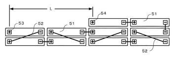
たとえば、図7は、全体を立方体に近い構成とした直列接続の一例であって、複数のセル51を平行に配置して、各セル51間をバスバー52で接続したものである。このような従来技術では、モジュールの両端に正極端子53と負極端子54が位置するため両極からの配線の引出方向が異なり、両極の配線をまとめるためにはモジュールを横切った配線が必要となる共に、配線長Lも長くなる。
For example, FIG. 7 is an example of a series connection in which the entire structure is close to a cube, and a plurality of
その上、電動アシスト自転車などのように電池パックの配置スペースに制限がある場合では、パック設置の都合上、直方体で平たいモジュールが要求され、長い配線は立方体に近い構造に比べ、体積効率を著しく低下させる。例えば、図8に示す電動アシスト自転車に使用される電池パックでは、10個の薄型のセル51がバスバー52を利用して直列に接続され、しかも、その厚さも3セル程度までに制限されている。
In addition, when the battery pack placement space is limited, such as a power-assisted bicycle, a flat module with a rectangular parallelepiped is required for the convenience of installing the pack, and long wires have significantly higher volume efficiency than a structure close to a cube. Reduce. For example, in the battery pack used for the electric assist bicycle shown in FIG. 8, ten
その結果、直列接続されたモジュールの端子から外部に電力を取り出すには、モジュールの端部に位置する正極端子53と負極端子54に配線を接続することになり、モジュールを横断するような長い配線長Lが必要となる。また、各セル間の接続抵抗を低減するには剛性の高いバスバーなどの導電部材を使用することが望ましいが、複数のバスバーを1本ずつ交差することがないように、しかも、ばらばらに用意された個々のセルに対して接続することは面倒な作業であり、接続ミスも発生する問題があった。
As a result, in order to extract the power from the terminals of the modules connected in series, the wiring is connected to the
以上のように、従来技術においては、個々の電池セルを1つずつバスバーで直列接続するため、接続の作業性が低く、接続ミスも生じやすいと共に、直列接続したモジュール両端の端子から外部に電力を引き出していたため、配線長が長くなる問題点があった。 As described above, in the prior art, since individual battery cells are connected in series with a bus bar one by one, connection workability is low, connection errors are likely to occur, and electric power is externally supplied from terminals at both ends of the modules connected in series. As a result, the wiring length becomes long.
本発明は前記のような従来技術の問題点を解決するために提案されたものであって、その目的は、バスバーによって接続された複数のセルをユニット化し、このユニットを他のユニットあるいはセルと組み合わせて接続して電池モジュールを構成することにより、複数のセルを直列接続したモジュールにおいても外部接続用の端子が同一方向となりモジュールを横断するような配線が発生せず、また、モジュール作成時においてはユニット間のバスバーの接続のみを実施することで、作業性の向上と接続ミスの削減を可能とした電池パックを提供することにある。 The present invention has been proposed in order to solve the problems of the prior art as described above, and its object is to unitize a plurality of cells connected by a bus bar, and to connect this unit with other units or cells. By connecting battery cells in combination, a module with multiple cells connected in series does not generate wiring that crosses the module with external connection terminals in the same direction. Is to provide a battery pack that can improve workability and reduce connection errors by only connecting the bus bars between the units.
前記の目的を達成するために、本発明は、それぞれ正極端子と負極端子を有する3個のセルを平行に配置し、且つ電気的に直列接続してなる電池パックにおいて、前記3個のセルのうち、2つのセルについては正極端子と負極端子とが同一方向に配置され、残る1つのセルについては他の2つのセルと反対方向に正極端子と負極端子が配置され、直列接続する2つのセルのうち、正極と負極を同一方向に配置した2つのセルについては、斜め方向のバスバーにより隣接するセルの正極端子と負極端子とが接続され、直列接続する2つのセルのうち、正極と負極を反対方向に配置した2つのセルについては、セルの長さ方向と直交するバスバーにより隣接するセルの正極端子と負極端子とが接続され、外部配線接続用の正極端子と負極端子とが、平行に配置した3個のセルの同一方向に配置されていることを特徴とする。 In order to achieve the above object, the present invention provides a battery pack in which three cells each having a positive electrode terminal and a negative electrode terminal are arranged in parallel and electrically connected in series. Among them, for two cells, a positive electrode terminal and a negative electrode terminal are arranged in the same direction, and for the remaining one cell, a positive electrode terminal and a negative electrode terminal are arranged in the opposite direction to the other two cells, and two cells connected in series Among the two cells in which the positive electrode and the negative electrode are arranged in the same direction, the positive electrode terminal and the negative electrode terminal of the adjacent cells are connected by an oblique bus bar. For two cells arranged in opposite directions, the positive and negative terminals of the adjacent cells are connected by a bus bar orthogonal to the cell length direction, and the positive and negative terminals for external wiring connection are connected. Characterized in that it is arranged in the same direction of the three cells were arranged in parallel.
また、前記の3個ユニットを2つのセルを直列に接続して成る2個ユニットと組み合わせて、配線接続用の端子を同一方向に配置したものも、本発明の一態様である。更に、これら3個ユニットと2個ユニットに加え、他のユニットを直列接続することで、より多くのセルを直列接続し、しかも、配線接続用の端子を同一方向に近接配置したものも、本発明の一態様である。 Another embodiment of the present invention is that the three units are combined with two units formed by connecting two cells in series and the terminals for wiring connection are arranged in the same direction. Furthermore, in addition to these three units and two units, other units are connected in series, so that more cells are connected in series and wiring connection terminals are arranged close to each other in the same direction. It is one embodiment of the invention.
本発明によれば、電池モジュールの配線接続用端子を同一方向に近接配置できるので、モジュールを横切る配線が不要となる。また、複数のセルを備えた3個ユニットや2個ユニットを使用して、より多数のセルを有するモジュールを作製するので、多数のセルの接続作業が効率化する。 According to the present invention, since the wiring connection terminals of the battery module can be arranged close to each other in the same direction, wiring crossing the module becomes unnecessary. Moreover, since a module having a larger number of cells is produced using three units or two units each having a plurality of cells, the connection work of the large number of cells is made efficient.
(1)第1実施形態
以下、本発明の第1実施形態を図1乃至図3に従って具体的に説明する。
(1) First Embodiment Hereinafter, a first embodiment of the present invention will be described in detail with reference to FIGS.
図1(A)は、本実施形態の電池パックにおける3個ユニット1を示すものである。この3個ユニット1は、3個の平板状のセル2a〜2cをその長さ方向に沿って平行に配置したものであり、各セル2a〜2cの上部には、それぞれ正極端子3と負極端子4とが設けられている。この場合、第1と第2のセル2a,2bについてはその正極端子3と負極端子4が同じ方向に配置され、第3のセルについては正極端子3と負極端子4が反対方向に配置されている。
FIG. 1A shows the three
第1のセル2aの負極端子4と第2のセル2bの正極端子3間は斜め方向に配置された第1のバスバー5により、また、第2のセル2bの負極端子4と第3のセル2cの正極端子間はセルの長さ方向と直交する方向に配置された第2のバスバー6により接続されている。これにより、第1のセル2aから第3のセル2cが直列に接続され、しかも、第1のセル2aの正極端子3と第3のセル2cの負極端子4が同じ方向に配置されている。
Between the
図2(A)は、本実施形態の電池パックにおける2個ユニット11を示すものである。この2個ユニット11は、2個の平板状のセル12a,12bをその長さ方向に沿って平行に配置したものであり、各セル12a,12bの上部には、それぞれ正極端子13と負極端子14とが設けられている。この場合、第1と第2のセル12a,12bの正極端子13と負極端子14は反対方向に配置されている。
FIG. 2A shows the two
第1のセル12aの負極端子14と第2のセル12bの正極端子13間は、セルの長さ方向と直交する方向に配置された第2のバスバー16により接続されている。これにより、第1のセル12aと第2のセル12bが直列に接続され、しかも、第1のセル12aの正極端子13と第2のセル2bの負極端子14が同じ方向に配置されている。
The
なお、図1及び図2に示す3個ユニット1と2個ユニット11については、外部の配線を接続する正極端子と負極端子の位置を対称形に配置したものも、本実施形態の一態様である。その構成を、それぞれ図1(B)と図2(B)に示す。更に、2個ユニット11については、図2(A)(B)の実施形態では、前記3個ユニット11と同一の外径寸法を得るために、2つのセル12a,12bがセル1個分の間隔を保って配置したが、図2(C)のように2つのセルを近接配置して、3個ユニット1の2/3の幅寸法とすることも可能である。なお、図示しないが、図2(C)の正極、負極端子の位置を対称形に配置したものも、本実施形態の一態様である。
Note that the three
また、これら図1(A)(B)及び図2(A)(B)に示す各ユニットについては、図中一点鎖線で示すように、筐体30内に収容しておくことが望ましい。その場合、筐体30からは、外部配線接続用の正極端子及び負極端子のみを露出させ、他の端子やセル間を接続するバスバーについては、筐体内に収めておくことが望ましい。また、図示しないが、この筐体30の外部には、接続用の係合部(爪とそれを引っかける凹部など)を設けておくこともできる。
In addition, it is desirable that the units shown in FIGS. 1A and 1B and FIGS. 2A and 2B are accommodated in the
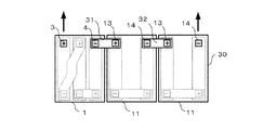
本実施形態の電池パックは、前記のような3個ユニット1及び2個ユニット11を組み合わせてなるものである。図3は、3個ユニット1を1つ、2個ユニット11を2つ組み合わせることで、8個のセルを直列接続したものである。この場合、図1(A)に示す3個ユニット1と、図2(A)及び(B)に示す2個ユニット11を隣接して配置し、これら各ユニット1,11の正極端子負極端子を外部接続用のバスバー31,32によって接続することにより、7個の電池セルが直列に接続された電池モジュールを得ることができる。
The battery pack of this embodiment is a combination of the three
この図3の電池モジュールでは、7個の電池セルが体積が小さな立方体状に集約して配置されているが、モジュールの両端に設けられた外部配線接続用の正極端子と負極端子は、モジュールの同一方向に配置されている。その結果、前記図7に示した従来技術のように、モジュールを横切って配線を行う必要がない利点がある。しかも、7個のセルを直列に接続する場合に、予め用意された3つのユニットを2本の外部配線用のバスバー31,32によって接続すれば良いので、接続作業が容易になり、ミスも防止できる。更に、前記のように筐体30に接続用の係合部を設けておけば、ユニット間の位置ズレもなく、外部接続用バスバーの取り付け作業も精度良く実施できる。
In the battery module of FIG. 3, seven battery cells are arranged in a small cubic shape, but the positive and negative terminals for connecting external wiring provided at both ends of the module are connected to the module. They are arranged in the same direction. As a result, there is an advantage that it is not necessary to perform wiring across the module as in the prior art shown in FIG. Moreover, when seven cells are connected in series, three units prepared in advance can be connected by the two
(2)第2実施形態
図4は、前記図1及び図2に示す3個ユニット1と2個ユニット11に加え、同じく3個あるいは2個のセルを筐体30内に収納して成る他の3個ユニット1’と2個ユニット11’を使用して、10個のセルを直列に接続したものである。
(2) Second Embodiment FIG. 4 shows a configuration in which three or two cells are housed in a
この実施形態において、他の3個ユニット1’は、図1の3個ユニット1と同様に、隣接するセルの正極端子と負極端子を接続する斜めのバスバー34を備えているが、他の正極端子または負極端子はユニット内のセル同士を接続するものではなく、他のユニットの端子に対し外部接続用バスバーにより接続されるものである。同様に、他の2個ユニット11’は筐体30内に2つのセルを収納したものであるが、隣接するセル同士を接続するバスバーは持たず、他のユニットの端子に対し外部接続用バスバーにより接続されるものである。
In this embodiment, the other three
本実施形態では、前記のような4種類のユニットを、2個ユニット11、2個ユニット11’、3個ユニット1’及び3個ユニット1の順で、セル3個分の厚さが最大幅となるように細長く配置し、隣接するユニット間の正極端子と負極端子を外部接続用バスバー33によって接続することで、電池モジュールを形成している。
In the present embodiment, the four types of units as described above are arranged in the order of 2
このような構成の第2実施形態によれば、モジュールの端部に図1に示す3個ユニット1と図2に示す2個ユニット11とを配置すると共に、その間に配置する他の3個ユニット1’及び2個ユニット11’のセルの方向と外部接続用バスバー33,34の接続構造を工夫することにより、電池モジュールに接続する正極側と負極側の配線の位置を近接することができ、配線長の短縮及び配線がモジュールを横切るような不都合の解消が可能となる。また、予め用意された3個ユニット1及び2個ユニット11を使用することにより、接続作業の簡易化、接続ミスの削減も前記図3の実施形態と同様に期待できる。
According to the second embodiment having such a configuration, the three
(3)他の実施形態
本発明は、前記の実施形態に限定されるものではなく、次のような他の実施形態も包含するものである。
(3) Other Embodiments The present invention is not limited to the above-described embodiments, and includes the following other embodiments.
(1) 3個ユニットと2個ユニットを必ず組み合わせて使用する必要はなく、モジュールが必要とするセル数によっては、複数の3個ユニットのみを組み合わせてモジュールを形成する。例えば、図4の実施形態において、最も左に位置する2個ユニット11を除けば、8個のセルによって配線用の端子を近接配置したモジュールを得ることができ、3個ユニット1と3個ユニット1’のみを組み合わせれば、6個のセルで同様な作用効果が期待できる。
(1) It is not necessary to use a combination of three units and two units, and depending on the number of cells required by the module, only a plurality of three units are combined to form a module. For example, in the embodiment of FIG. 4, except for the two
(2) 図4の実施形態における他の3個ユニット1’では、隣接するセルを斜めの外部接続用バスバー34により接続したが、この外部接続用バスバー34の代わりに、図1の3個ユニット1と同様に、予め斜めの内部接続用バスバー5によって接続しておくこともできる。その場合、モジュールの作成時に、筐体30内に収納されているセル同士の端子を接続する作業が不要となり、作業効率が向上する。
(2) In the other three
(3) 図1(C)に示すように、斜め方向の内部接続用バスバー5が、3つのセルの両側に位置するセル同士を接続する。この実施形態においては、内部接続用バスバー5が長くなるものの、3個ユニット1に接続する配線をより近接させることができる。
(3) As shown in FIG. 1C, the internal
(4) 図5に示すように、2つの3個ユニット1と3つの2個ユニット11を接続して電池モジュールを構成したり、図6に示すように、4つの3個ユニット1を接続して電池モジュールを構成することもできる。なお、図6の接続構成は、4つの2個ユニットを接続して電池モジュールを構成する場合にも、同様に採用できる。
(4) As shown in FIG. 5, two three
1,1’…3個ユニット
2a〜2c…セル
3…正極端子
4…負極端子
5,6…内部接続用バスバー
11,11’…2個ユニット
12a,12b…セル
13…正極端子
14…負極端子
16…バスバー
30…筐体
31,32,33,34…外部接続用バスバー
DESCRIPTION OF
Claims (4)
前記3個のセルのうち、2つのセルについては正極端子と負極端子とが同一方向に配置され、残る1つのセルについては他の2つのセルと反対方向に正極端子と負極端子が配置され、
直列接続する2つのセルのうち、正極と負極を同一方向に配置した2つのセルについては、斜め方向のバスバーにより隣接するセルの正極端子と負極端子とが接続され、
直列接続する2つのセルのうち、正極と負極を反対方向に配置した2つのセルについては、セルの長さ方向と直交するバスバーにより隣接するセルの正極端子と負極端子とが接続され、
外部配線接続用の正極端子と負極端子とが、平行に配置した3個のセルの同一方向に配置されていることを特徴とする電池パック。 In a battery pack in which three cells each having a positive electrode terminal and a negative electrode terminal are arranged in parallel and electrically connected in series,
Among the three cells, the positive electrode terminal and the negative electrode terminal are arranged in the same direction for two cells, and the positive electrode terminal and the negative electrode terminal are arranged in the opposite direction to the other two cells for the remaining one cell,
Among the two cells connected in series, for the two cells in which the positive electrode and the negative electrode are arranged in the same direction, the positive electrode terminal and the negative electrode terminal of the adjacent cells are connected by an oblique bus bar,
Among the two cells connected in series, for the two cells in which the positive electrode and the negative electrode are arranged in opposite directions, the positive electrode terminal and the negative electrode terminal of the adjacent cells are connected by a bus bar orthogonal to the cell length direction,
A battery pack, wherein a positive electrode terminal and a negative electrode terminal for external wiring connection are arranged in the same direction of three cells arranged in parallel.
この2個ユニットにおける外部配線接続用の正極端子と負極端子とが、平行に配置した2個のセルの同一方向に配置され、
この2個ユニットと請求項1に記載の3個ユニットがバスバーにより直列に接続され、この直列に接続された2個ユニットと3個ユニットから成る電池モジュールの外部配線接続用の正極端子と負極端子が電池モジュールの同一方向に配置されていることを特徴とする電池パック。 Two cells each having a positive electrode terminal and a negative electrode terminal are arranged so that the positive electrode and the negative electrode are in opposite directions, and the positive electrode terminal and the negative electrode terminal of these two cells are connected by a bus bar orthogonal to the length direction of the cell. Two units are formed by connecting two cells electrically in series,
The positive terminal and the negative terminal for external wiring connection in these two units are arranged in the same direction of two cells arranged in parallel,
The two units and the three units according to claim 1 are connected in series by a bus bar, and the positive terminal and the negative terminal for connecting the external wiring of the battery module comprising the two units connected in series and the three units. Are arranged in the same direction of the battery module.
モジュールの両端に請求項1の3個ユニットと2個ユニットが位置するように、2つの2個ユニット同士と2つの3個ユニット同士が隣接して配置され、
各ユニットの端子間、及び請求項1の3個ユニットを構成するセルの端子間がバスバーによって接続されていることを特徴とする電池パック。 The three units according to claim 1 and the two units according to claim 2, and another three units formed by arranging three cells in parallel, and other units formed by arranging two cells in parallel. In a battery pack in which 10 cells composed of 2 units are connected in series,
Two two units and two three units are arranged adjacent to each other so that the three units and two units of claim 1 are located at both ends of the module,
A battery pack characterized in that the terminals of each unit and the terminals of the cells constituting the three units of claim 1 are connected by a bus bar.
Priority Applications (7)
| Application Number | Priority Date | Filing Date | Title |
|---|---|---|---|
| JP2007255903A JP2009087720A (en) | 2007-09-28 | 2007-09-28 | Battery pack |
| EP08832856A EP2202825A1 (en) | 2007-09-28 | 2008-09-24 | Battery pack |
| KR1020107005775A KR20100055477A (en) | 2007-09-28 | 2008-09-24 | Battery pack |
| US12/680,589 US20100266887A1 (en) | 2007-09-28 | 2008-09-24 | Battery pack |
| PCT/JP2008/002625 WO2009041018A1 (en) | 2007-09-28 | 2008-09-24 | Battery pack |
| CN200880108799A CN101809786A (en) | 2007-09-28 | 2008-09-24 | Battery pack |
| TW097137012A TW200924259A (en) | 2007-09-28 | 2008-09-26 | Battery pack |
Applications Claiming Priority (1)
| Application Number | Priority Date | Filing Date | Title |
|---|---|---|---|
| JP2007255903A JP2009087720A (en) | 2007-09-28 | 2007-09-28 | Battery pack |
Publications (1)
| Publication Number | Publication Date |
|---|---|
| JP2009087720A true JP2009087720A (en) | 2009-04-23 |
Family
ID=40510925
Family Applications (1)
| Application Number | Title | Priority Date | Filing Date |
|---|---|---|---|
| JP2007255903A Pending JP2009087720A (en) | 2007-09-28 | 2007-09-28 | Battery pack |
Country Status (7)
| Country | Link |
|---|---|
| US (1) | US20100266887A1 (en) |
| EP (1) | EP2202825A1 (en) |
| JP (1) | JP2009087720A (en) |
| KR (1) | KR20100055477A (en) |
| CN (1) | CN101809786A (en) |
| TW (1) | TW200924259A (en) |
| WO (1) | WO2009041018A1 (en) |
Cited By (8)
| Publication number | Priority date | Publication date | Assignee | Title |
|---|---|---|---|---|
| DE102010035580A1 (en) | 2009-08-27 | 2011-03-10 | Kabushiki Kaisha Toshiba | battery |
| DE102010035458A1 (en) | 2009-08-26 | 2011-08-04 | Kabushiki Kaisha Toshiba | battery |
| JP2014022098A (en) * | 2012-07-13 | 2014-02-03 | Mitsubishi Motors Corp | Battery pack |
| US8808903B2 (en) | 2010-06-21 | 2014-08-19 | Kabushiki Kaisha Toshiba | Battery with wound electrode group and positive and negative electrode insulating covers |
| JP2016027578A (en) * | 2009-09-30 | 2016-02-18 | 株式会社東芝 | Secondary battery device |
| US9276250B2 (en) | 2010-08-26 | 2016-03-01 | Samsung Sdi Co., Ltd. | Battery array and battery pack having the same |
| CN107425161A (en) * | 2016-05-24 | 2017-12-01 | 丰田自动车株式会社 | Battery case |
| KR20190079367A (en) * | 2017-12-27 | 2019-07-05 | 삼성에스디아이 주식회사 | Battery pack |
Families Citing this family (36)
| Publication number | Priority date | Publication date | Assignee | Title |
|---|---|---|---|---|
| WO2008032795A1 (en) | 2006-09-14 | 2008-03-20 | National University Corporation Shizuoka University | Electrolytic solution for electrochemical device |
| KR101136310B1 (en) * | 2010-06-07 | 2012-04-19 | 에스비리모티브 주식회사 | Battery pack |
| KR101191662B1 (en) | 2010-11-05 | 2012-10-17 | 에스비리모티브 주식회사 | Battery module |
| KR101201748B1 (en) | 2010-11-05 | 2012-11-15 | 에스비리모티브 주식회사 | Battery modual |
| KR101223520B1 (en) | 2010-11-10 | 2013-01-17 | 로베르트 보쉬 게엠베하 | Battery module |
| KR101287108B1 (en) | 2011-08-25 | 2013-07-17 | 로베르트 보쉬 게엠베하 | Secondary battery module |
| KR101287107B1 (en) | 2011-08-25 | 2013-07-17 | 로베르트 보쉬 게엠베하 | Battery module with connecting member |
| JP5672218B2 (en) * | 2011-11-23 | 2015-02-18 | 株式会社デンソー | Assembled battery |
| DE102012217600A1 (en) * | 2012-09-27 | 2014-03-27 | Robert Bosch Gmbh | Battery and motor vehicle with battery |
| JP2014191968A (en) * | 2013-03-27 | 2014-10-06 | Toyoda Gosei Co Ltd | Battery device |
| DE112013000093T5 (en) * | 2013-08-02 | 2015-07-23 | Komatsu Ltd. | Battery for a work vehicle and battery-type work vehicle |
| WO2015076034A1 (en) * | 2013-11-22 | 2015-05-28 | 株式会社オートネットワーク技術研究所 | Connection structure for electrical storage element group |
| CN104064720A (en) * | 2014-07-09 | 2014-09-24 | 深圳市格瑞普电池有限公司 | Lithium ion battery pack capable of outputting multiple voltages |
| JP2017142923A (en) * | 2016-02-09 | 2017-08-17 | 株式会社オートネットワーク技術研究所 | Bus bar and method of manufacturing bus bar |
| DE102016121265A1 (en) * | 2016-11-07 | 2018-05-09 | Elringklinger Ag | Cell contacting system for an electrochemical device |
| JP6629710B2 (en) * | 2016-11-08 | 2020-01-15 | トヨタ自動車株式会社 | Battery pack |
| CN110337736B (en) * | 2017-02-06 | 2024-03-12 | 日本汽车能源株式会社 | Battery pack and bracket |
| JP6856423B2 (en) * | 2017-03-29 | 2021-04-07 | ビークルエナジージャパン株式会社 | Battery pack |
| WO2019132155A1 (en) * | 2017-12-28 | 2019-07-04 | 삼성에스디아이 주식회사 | Battery module |
| CN108091788A (en) * | 2018-01-31 | 2018-05-29 | 北京国能电池科技股份有限公司 | Battery case and batter-charghing system |
| KR20190130927A (en) * | 2018-05-15 | 2019-11-25 | 삼성에스디아이 주식회사 | Battery pack |
| CN208444901U (en) | 2018-05-18 | 2019-01-29 | 长城汽车股份有限公司 | Battery modules and the battery pack for vehicle with it |
| CN108777312A (en) * | 2018-06-10 | 2018-11-09 | 沈建冬 | A kind of battery that can be complementary |
| KR102640327B1 (en) | 2018-10-19 | 2024-02-22 | 삼성에스디아이 주식회사 | Large module of battery |
| KR102640329B1 (en) | 2018-10-19 | 2024-02-22 | 삼성에스디아이 주식회사 | Battery module |
| KR102640328B1 (en) | 2018-10-19 | 2024-02-22 | 삼성에스디아이 주식회사 | Large module of battery |
| KR20200044582A (en) | 2018-10-19 | 2020-04-29 | 삼성에스디아이 주식회사 | Large module of battery |
| KR102646853B1 (en) | 2018-10-19 | 2024-03-11 | 삼성에스디아이 주식회사 | Battery module |
| KR102646854B1 (en) | 2018-10-19 | 2024-03-11 | 삼성에스디아이 주식회사 | Battery module |
| CN209104250U (en) * | 2018-11-19 | 2019-07-12 | 宁德时代新能源科技股份有限公司 | Battery modules |
| CN109768206A (en) * | 2018-12-20 | 2019-05-17 | 深圳市溢骏科技有限公司 | Power battery pack |
| CN209730034U (en) * | 2019-01-18 | 2019-12-03 | 宁德时代新能源科技股份有限公司 | A kind of battery module |
| CN110707253B (en) * | 2019-09-24 | 2022-04-29 | 天能电池集团股份有限公司 | Storage battery pack |
| CN112310575B (en) * | 2020-04-03 | 2022-11-29 | 宁德时代新能源科技股份有限公司 | Battery module, battery pack, and device using secondary battery |
| EP3923409B1 (en) * | 2020-04-03 | 2023-03-15 | Contemporary Amperex Technology Co., Limited | Battery module, battery pack, and apparatus using battery as power source |
| JP2022126922A (en) * | 2021-02-19 | 2022-08-31 | トヨタ自動車株式会社 | Battery pack |
Family Cites Families (6)
| Publication number | Priority date | Publication date | Assignee | Title |
|---|---|---|---|---|
| JPS5035633U (en) * | 1973-07-04 | 1975-04-15 | ||
| JPS556043Y2 (en) * | 1974-11-19 | 1980-02-12 | ||
| JPS62140673U (en) * | 1986-02-27 | 1987-09-04 | ||
| US5709280A (en) * | 1995-10-13 | 1998-01-20 | Gnb Technologies, Inc. | Sealed lead-acid cell tray assembly and motive powered vehicle using such cell tray assembly |
| JP4428905B2 (en) * | 2002-02-01 | 2010-03-10 | 日本電気株式会社 | Flat battery and battery pack using the same |
| JP2004200017A (en) | 2002-12-19 | 2004-07-15 | Matsushita Electric Ind Co Ltd | Storage battery |
-
2007
- 2007-09-28 JP JP2007255903A patent/JP2009087720A/en active Pending
-
2008
- 2008-09-24 CN CN200880108799A patent/CN101809786A/en active Pending
- 2008-09-24 KR KR1020107005775A patent/KR20100055477A/en not_active Application Discontinuation
- 2008-09-24 US US12/680,589 patent/US20100266887A1/en not_active Abandoned
- 2008-09-24 EP EP08832856A patent/EP2202825A1/en not_active Withdrawn
- 2008-09-24 WO PCT/JP2008/002625 patent/WO2009041018A1/en active Application Filing
- 2008-09-26 TW TW097137012A patent/TW200924259A/en unknown
Cited By (22)
| Publication number | Priority date | Publication date | Assignee | Title |
|---|---|---|---|---|
| US9203059B2 (en) | 2009-08-26 | 2015-12-01 | Kabushiki Kaisha Toshiba | Battery with insulating member including bus bar fixing section |
| DE102010035458A1 (en) | 2009-08-26 | 2011-08-04 | Kabushiki Kaisha Toshiba | battery |
| DE102010035458B4 (en) | 2009-08-26 | 2021-07-15 | Kabushiki Kaisha Toshiba | battery |
| US8574753B2 (en) | 2009-08-27 | 2013-11-05 | Kabushiki Kaisha Toshiba | Battery comprising a conductive nipping member |
| US9034499B2 (en) | 2009-08-27 | 2015-05-19 | Kabushiki Kaisha Toshiba | Battery comprising multiple insulating covers |
| DE102010035580A1 (en) | 2009-08-27 | 2011-03-10 | Kabushiki Kaisha Toshiba | battery |
| US10115937B2 (en) | 2009-08-27 | 2018-10-30 | Kabushiki Kaisha Toshiba | Battery including branched current collector sections |
| JP2016027578A (en) * | 2009-09-30 | 2016-02-18 | 株式会社東芝 | Secondary battery device |
| US8808903B2 (en) | 2010-06-21 | 2014-08-19 | Kabushiki Kaisha Toshiba | Battery with wound electrode group and positive and negative electrode insulating covers |
| US11158898B2 (en) | 2010-06-21 | 2021-10-26 | Kabushiki Kaisha Toshiba | Battery with wound electrode group and positive and negative electrode insulating covers |
| US10468641B2 (en) | 2010-06-21 | 2019-11-05 | Kabushiki Kaisha Toshiba | Battery with wound electrode group and positive and negative electrode insulating covers |
| US9899641B2 (en) | 2010-06-21 | 2018-02-20 | Kabushiki Kaisha Toshiba | Battery with wound electrode group and positive and negative electrode insulating covers |
| US9276250B2 (en) | 2010-08-26 | 2016-03-01 | Samsung Sdi Co., Ltd. | Battery array and battery pack having the same |
| JP2014022098A (en) * | 2012-07-13 | 2014-02-03 | Mitsubishi Motors Corp | Battery pack |
| US9419263B2 (en) | 2012-07-13 | 2016-08-16 | Mitsubishi Jidosha Kogyo Kabushiki Kaisha | Battery pack |
| CN107425161A (en) * | 2016-05-24 | 2017-12-01 | 丰田自动车株式会社 | Battery case |
| CN107425161B (en) * | 2016-05-24 | 2020-05-26 | 丰田自动车株式会社 | Battery box |
| US10553909B2 (en) | 2016-05-24 | 2020-02-04 | Toyota Jidosha Kabushiki Kaisha | Battery pack |
| JP2021504896A (en) * | 2017-12-27 | 2021-02-15 | 三星エスディアイ株式会社Samsung SDI Co., Ltd. | Battery pack |
| KR20190079367A (en) * | 2017-12-27 | 2019-07-05 | 삼성에스디아이 주식회사 | Battery pack |
| JP7026792B2 (en) | 2017-12-27 | 2022-02-28 | 三星エスディアイ株式会社 | Battery pack |
| KR102519443B1 (en) * | 2017-12-27 | 2023-04-07 | 삼성에스디아이 주식회사 | Battery pack |
Also Published As
| Publication number | Publication date |
|---|---|
| EP2202825A1 (en) | 2010-06-30 |
| KR20100055477A (en) | 2010-05-26 |
| WO2009041018A1 (en) | 2009-04-02 |
| US20100266887A1 (en) | 2010-10-21 |
| TW200924259A (en) | 2009-06-01 |
| CN101809786A (en) | 2010-08-18 |
Similar Documents
| Publication | Publication Date | Title |
|---|---|---|
| JP2009087720A (en) | Battery pack | |
| US7642746B2 (en) | Method of preparing battery core pack | |
| JP5490516B2 (en) | Battery pack | |
| JP5494748B2 (en) | Battery wiring module | |
| JP5881993B2 (en) | Battery array and battery pack having the same | |
| JP2012156131A (en) | Battery module | |
| CN104241580A (en) | Bus bar module and power unit | |
| JP6215358B2 (en) | Busbar module and battery pack | |
| US20110195285A1 (en) | Voltage sensing member and battery module employed with the same | |
| JP6528411B2 (en) | battery | |
| JP2013105698A (en) | Power supply device | |
| WO2017187959A1 (en) | Connection module | |
| KR101219233B1 (en) | Battery array and battery pack having the same | |
| JP5836174B2 (en) | Solar cell module | |
| JP2019036475A (en) | Bus bar module and battery pack | |
| JP2018056063A (en) | Connection module | |
| JP2008226519A (en) | Battery pack | |
| JP2004319342A (en) | Battery pack and battery module | |
| JP5887724B2 (en) | Power supply module connection structure | |
| JP2004127775A (en) | Fuel cell | |
| JP6636340B2 (en) | Battery pack | |
| JP2019008875A (en) | Wire connection bus bar and conductive module | |
| JP2012084467A (en) | Bus bar and coupled bus bar group | |
| JP2019204658A (en) | Battery module | |
| JP2019079651A (en) | Electric connection member |