KR20200039687A - Quick clamping device - Google Patents
Quick clamping device Download PDFInfo
- Publication number
- KR20200039687A KR20200039687A KR1020207003870A KR20207003870A KR20200039687A KR 20200039687 A KR20200039687 A KR 20200039687A KR 1020207003870 A KR1020207003870 A KR 1020207003870A KR 20207003870 A KR20207003870 A KR 20207003870A KR 20200039687 A KR20200039687 A KR 20200039687A
- Authority
- KR
- South Korea
- Prior art keywords
- clamping device
- quick clamping
- locking
- cam mechanism
- unit
- Prior art date
Links
Images


Classifications
-
- B—PERFORMING OPERATIONS; TRANSPORTING
- B24—GRINDING; POLISHING
- B24B—MACHINES, DEVICES, OR PROCESSES FOR GRINDING OR POLISHING; DRESSING OR CONDITIONING OF ABRADING SURFACES; FEEDING OF GRINDING, POLISHING, OR LAPPING AGENTS
- B24B45/00—Means for securing grinding wheels on rotary arbors
- B24B45/006—Quick mount and release means for disc-like wheels, e.g. on power tools
-
- B—PERFORMING OPERATIONS; TRANSPORTING
- B24—GRINDING; POLISHING
- B24B—MACHINES, DEVICES, OR PROCESSES FOR GRINDING OR POLISHING; DRESSING OR CONDITIONING OF ABRADING SURFACES; FEEDING OF GRINDING, POLISHING, OR LAPPING AGENTS
- B24B23/00—Portable grinding machines, e.g. hand-guided; Accessories therefor
- B24B23/02—Portable grinding machines, e.g. hand-guided; Accessories therefor with rotating grinding tools; Accessories therefor
- B24B23/022—Spindle-locking devices, e.g. for mounting or removing the tool
-
- B—PERFORMING OPERATIONS; TRANSPORTING
- B24—GRINDING; POLISHING
- B24B—MACHINES, DEVICES, OR PROCESSES FOR GRINDING OR POLISHING; DRESSING OR CONDITIONING OF ABRADING SURFACES; FEEDING OF GRINDING, POLISHING, OR LAPPING AGENTS
- B24B23/00—Portable grinding machines, e.g. hand-guided; Accessories therefor
- B24B23/02—Portable grinding machines, e.g. hand-guided; Accessories therefor with rotating grinding tools; Accessories therefor
- B24B23/028—Angle tools
-
- B—PERFORMING OPERATIONS; TRANSPORTING
- B24—GRINDING; POLISHING
- B24B—MACHINES, DEVICES, OR PROCESSES FOR GRINDING OR POLISHING; DRESSING OR CONDITIONING OF ABRADING SURFACES; FEEDING OF GRINDING, POLISHING, OR LAPPING AGENTS
- B24B23/00—Portable grinding machines, e.g. hand-guided; Accessories therefor
- B24B23/04—Portable grinding machines, e.g. hand-guided; Accessories therefor with oscillating grinding tools; Accessories therefor
-
- B—PERFORMING OPERATIONS; TRANSPORTING
- B25—HAND TOOLS; PORTABLE POWER-DRIVEN TOOLS; MANIPULATORS
- B25F—COMBINATION OR MULTI-PURPOSE TOOLS NOT OTHERWISE PROVIDED FOR; DETAILS OR COMPONENTS OF PORTABLE POWER-DRIVEN TOOLS NOT PARTICULARLY RELATED TO THE OPERATIONS PERFORMED AND NOT OTHERWISE PROVIDED FOR
- B25F5/00—Details or components of portable power-driven tools not particularly related to the operations performed and not otherwise provided for
- B25F5/001—Gearings, speed selectors, clutches or the like specially adapted for rotary tools
-
- B—PERFORMING OPERATIONS; TRANSPORTING
- B27—WORKING OR PRESERVING WOOD OR SIMILAR MATERIAL; NAILING OR STAPLING MACHINES IN GENERAL
- B27B—SAWS FOR WOOD OR SIMILAR MATERIAL; COMPONENTS OR ACCESSORIES THEREFOR
- B27B5/00—Sawing machines working with circular or cylindrical saw blades; Components or equipment therefor
- B27B5/29—Details; Component parts; Accessories
- B27B5/30—Details; Component parts; Accessories for mounting or securing saw blades or saw spindles
- B27B5/32—Devices for securing circular saw blades to the saw spindle
Abstract
본 발명은 적어도 하나의 인서트 공구(10)를 전동 공구(12), 특히 앵글 그라인더 상에 배치하기 위한 퀵 클램핑 장치에 관한 것이며, 상기 퀵 클램핑 장치는 상기 인서트 공구(10)를 출력 유닛(14)의 출력 축(16)을 중심으로 이동시키기 위한 적어도 하나의 출력 유닛(14), 및 인서트 공구(10)를 출력 유닛(14) 상에 적어도 축방향으로 고정하기 위한 적어도 하나의 고정 유닛(20)을 포함하고, 상기 고정 유닛은 특히 탈착 불가능하게 출력 유닛(14) 상에 조립되고 이동 가능하게 지지된 적어도 하나의 고정 요소(18)를 포함한다. 퀵 클램핑 장치는 특히 이동 가능하게 지지된 적어도 하나의 록킹 요소(24)를 구비한 적어도 하나의 록킹 유닛(22)을 포함하고, 상기 록킹 요소(24)는 출력 유닛(14)에 대해 적어도 출력 축(16)을 중심으로 이동 가능하게 지지된 상기 고정 요소(18)가 출력 축(16)을 중심으로 이동하는 것을 방지하기 위해 제공된다. The present invention relates to a quick clamping device for placing at least one insert tool (10) on a power tool (12), in particular an angle grinder, wherein the quick clamping device outputs the insert tool (10) to an output unit (14). At least one output unit 14 for moving about the output axis 16 of the, and at least one fixing unit 20 for fixing the insert tool 10 on the output unit 14 at least axially Including, the fixing unit comprises at least one fixing element 18 which is particularly detachably assembled on the output unit 14 and movably supported. The quick clamping device particularly comprises at least one locking unit 22 with at least one locking element 24 movably supported, said locking element 24 being at least an output shaft relative to the output unit 14. It is provided to prevent the fixing element 18 movably supported around the 16 from moving around the output shaft 16.
Description
본 발명은 각각의 독립 청구항에 따른 퀵 클램핑 장치, 인서트 공구, 상기 퀵 클램핑 장치를 가진 전동 공구, 그리고 상기 퀵 클램핑 장치를 가진 전동 공구 및 인서트 공구를 포함한 전동 공구 시스템에 관한 것이다.The present invention relates to a power tool system including a quick clamping device, an insert tool, a power tool with the quick clamping device, and a power tool and insert tool with the quick clamping device according to each independent claim.
DE 103 61 810 A1에는 전동 공구 상에 적어도 하나의 인서트 공구를 배치하기 위한 퀵 클램핑 장치가 이미 공지되고, 퀵 클램핑 장치는 출력 유닛의 출력 축을 중심으로 인서트 공구를 이동시키기 위한 적어도 하나의 출력 유닛, 및 인서트 공구를 출력 유닛 상에 적어도 축 방향으로 고정하기 위한 적어도 하나의 고정 유닛을 포함하고, 상기 고정 유닛은 이동 가능하게 지지된 적어도 하나의 고정 요소를 구비한다.In DE 103 61 810 A1, a quick clamping device for placing at least one insert tool on a power tool is already known, the quick clamping device comprising at least one output unit for moving the insert tool about the output axis of the output unit, And at least one fixing unit for fixing the insert tool on the output unit at least axially, the fixing unit having at least one fixing element movably supported.
본 발명의 과제는 적어도 하나의 인서트 공구를 전동 공구, 특히 앵글 그라인더 상에 특히 공구 없이 고정 가능하게 배치하기 위한 퀵 클램핑 장치를 제공하는 것이다.An object of the present invention is to provide a quick clamping device for securely positioning at least one insert tool on a power tool, in particular an angle grinder, without a tool.
본 발명은 적어도 하나의 인서트 공구를 전동 공구, 특히 앵글 그라인더 상에 특히 공구 없이 고정 가능하게 배치하기 위한 퀵 클램핑 장치에 관한 것이며, 상기 퀵 클램핑 장치는 출력 유닛의 출력 축을 중심으로 인서트 공구를 이동시키기 위한 적어도 하나의 출력 유닛, 및 인서트 공구를 출력 유닛 상에 적어도 축 방향으로 고정하기 위한 적어도 하나의 고정 유닛을 포함하고, 상기 고정 유닛은 특히 탈착 불가능하게 출력 유닛 상에 조립되고 이동 가능하게 지지된 적어도 하나의 고정 요소를 구비한다.The present invention relates to a quick clamping device for securely positioning at least one insert tool on a power tool, in particular an angle grinder, without a tool, wherein the quick clamping device moves the insert tool around the output axis of the output unit. At least one output unit for fixing, and at least one fixing unit for fixing the insert tool on the output unit at least axially, the fixing unit being particularly detachably assembled on the output unit and movably supported. It has at least one fixing element.
퀵 클램핑 장치는 적어도 하나의, 특히 이동 가능하게 지지된 록킹 요소를 가진 적어도 하나의 록킹 유닛을 포함하고, 상기 록킹 요소는 출력 유닛에 대해 적어도 출력 축을 중심으로 이동 가능하게 지지된 고정 요소가 특히 적어도 하나의 작동 상태, 바람직하게는 개방 상태에서 출력 축을 중심으로 이동하는 것을 방지하기 위해 제공된다.The quick clamping device comprises at least one locking unit with at least one, in particular a movably supported locking element, said locking element having at least a fixed element movably supported relative to the output unit at least about an output axis. It is provided to prevent movement about the output axis in one operating state, preferably in an open state.
바람직하게는 높은 수준의 조작 편의성이 달성될 수 있다. 바람직하게는 인서트 공구를 전동 공구 상에 간단히 조립 및/또는 분해할 수 있으므로, 바람직하게는 특히 인서트 공구의 교환시 및/또는 전동 공구의 시동시 시간 절약이 달성된다. 특히, 기술된 구성에 의해 바람직하게는 퀵 클램핑 장치의 개방 상태가 독자적으로 및/또는 의도하지 않게 폐쇄되는 것이 방지될 수 있으므로, 예를 들어 인서트 공구가 직접, 특히 퀵 클램핑 장치의 재개방 없이 클램핑됨으로써 특히 효율 및/또는 사용자 친화성이 향상될 수 있다. 퀵 클램핑 장치는 바람직하게는 적은 수의 부품들을 포함하므로, 특히 생산 비용이 낮게 유지될 수 있다.Preferably, a high level of ease of operation can be achieved. Since the insert tool can preferably be simply assembled and / or disassembled on the power tool, time savings are preferably achieved, especially when changing the insert tool and / or starting the power tool. In particular, the described configuration can advantageously prevent the open state of the quick clamping device from being closed independently and / or unintentionally, such that the insert tool is clamped directly, in particular without re-opening the quick clamping device. This can improve efficiency and / or user friendliness in particular. The quick clamping device preferably contains a small number of parts, so the production cost can be kept low in particular.
바람직하게는 출력 유닛은 출력 축을 중심으로 하는 회전 및/또는 진동 운동을 고정 유닛에 의해 출력 유닛 상에 고정된 인서트 공구로 전달하기 위해 제공된다. 바람직하게는 출력 유닛은 당업자에게 이미 공지된 방식으로, 특히 구동 유닛의 적어도 하나의 구동 피니언을 통해, 전동 공구의 구동 유닛과 작용적으로 연결된다. 출력 유닛은 특히 적어도 하나의 슬리브 및/또는 적어도 하나의 중공 샤프트, 특히 중공 스핀들을 포함한다. 출력 유닛의 회전 및/또는 진동 운동은 적어도 하나의 전기 모터를 구비한 전동 공구의 구동 유닛과 출력 유닛의 상호 작용에 의해 바람직하게 생성될 수 있다. 구성 요소, 특히 고정 요소가 "탈착 불가능하게 조립된다는" 것은 구성 요소, 특히 고정 요소가 적어도 하나의 다른 구성 요소, 특히 출력 유닛 상에 분실 방지 방식으로 배치되고 및/또는 바람직하게는 작동 가능한 및/또는 작동 준비된 상태에서, 특히 퀵 클램핑 장치의 개방 상태 및 퀵 클램핑 장치의 폐쇄 상태에서, 특히 출력 유닛으로부터 분리될 수 없는 것을 의미한다. 바람직하게는 고정 요소는 출력 유닛 상에 분실 방지되게 배치된다. 특히, 출력 유닛 상에 분실 방지 방식으로 배치된 고정 요소 및/또는 출력 유닛 상에 분실 방지 방식으로 배치된 각각의 다른 구성 요소는 특히 퀵 클램핑 장치의 개방 상태 및/또는 폐쇄 상태에서 출력 유닛과 분실 불가능하게 연결된다. 퀵 클램핑 장치의 "개방 상태"는 특히 퀵 클램핑 장치 상에 배치된 인서트 공구를 분해를 위해 릴리즈하고 및/또는 인서트 공구를 퀵 클램핑 장치 상에 조립하기 위해 퀵 클램핑 장치를 릴리즈하는 퀵 클램핑 장치의 상태를 의미한다. 퀵 클램핑 장치의 "폐쇄 상태"는 인서트 공구가 출력 유닛 상에 작동 준비된 상태로 고정되어 있거나 및/또는 출력 유닛으로부터 인서트 공구의 특히 파손 없는 분해가 불가능한 퀵 클램핑 장치의 상태를 특히 의미한다. 고정 요소는 특히 퀵 클램핑 장치의 폐쇄 상태에서 인서트 공구, 특히 그라인딩 휠을 퀵 클램핑 장치 상에 홀딩하기 위해 압력 끼워맞춤 결합 및/또는 형상 끼워맞춤 결합을 형성하기 위해 제공된다. 고정 요소는 바람직하게는 출력 유닛의 적어도 일부에 대해 인서트 공구의 적어도 일부를 가압함으로써, 특히 축 방향 형상 끼워맞춤 결합을 바람직하게 형성한다. 고정 요소가 특히 축 방향 형상 끼워맞춤 결합에 추가해서, 방사 방향 및 또는 원주 방향으로의 형상 끼워맞춤 결합을 생성하는 것이 고려될 수 있고, 원주 방향은 그 표면 법선이 출력 축에 대해 평행하게 연장되는 평면에 놓인다. "공구 없이 고정 가능한"은 인서트 공구를 퀵 클램핑 장치 상에 배치하는 과정 및/또는 개방 상태와 폐쇄 상태 사이의 전환이 예를 들어 렌치, 앨런 키 등과 같은 외부 공구의 사용과 무관하게 달성될 수 있는 것을 의미한다. 고정 요소는 특히 축 방향으로 병진 운동식으로 및/또는 출력 축을 중심으로 하는 회전식으로, 특히 출력 유닛에 대해 이동 가능하게 지지되고, 바람직하게는 고정 요소의 이동 축, 특히 회전 축은 적어도 실질적으로 출력 축과 일치한다. 출력 유닛은 표면 법선이 특히 적어도 실질적으로 출력 축에 대해 평행하게 연장되는 평면에 놓인 원주 방향을 따라 적어도 부분적으로 고정 요소 둘레를 그립핑한다. 바람직하게는 출력 유닛은 고정 요소를 적어도 부분적으로 수용하기 위한 중공 샤프트를 포함한다. 록킹 유닛은 특히 적어도 하나, 바람직하게는 적어도 2 개, 더 바람직하게는 적어도 3 개, 더 바람직하게는 적어도 4 개 또는 특히 바람직하게는 적어도 다수의 록킹 요소들을 포함한다. 특히 개방 상태에서, 록킹 요소는 특히 개방 상태에서 고정 요소의 고정을 위해 고정 요소와의 적어도 하나의 형상 끼워맞춤 결합을 형성하기 위해 특히 제공된다. 바람직하게는 퀵 클램핑 장치의 개방 후, 록킹 요소는 고정 요소가 특히 폐쇄 위치 내로 회전되는 것 및/또는 복귀하는 것을 방지하기 위해 록킹 위치로 자동으로 이동된다. 록킹 요소의 자동 이동은 특히 예를 들어 스프링의 복원력에 의해 및/또는 예를 들어 록킹 유닛의 액추에이터를 통한 모터로 생성된 힘에 의해 이루어질 수 있다. 록킹 요소는 특히 원형으로, 각형으로 및/또는 평평하게 형성될 수 있는 이동 가능하게 지지된 볼트로서, 폴딩 가능한 힌지로서, 후크로서, 영구 자석으로서 또는 전자석으로서 형성될 수 있다. "제공되는"은 특히 특별하게 프로그래밍, 설계 및/또는 장착되는 것을 의미한다. 특정 기능을 위해 대상물이 제공된다는 것은, 상기 대상물이 적어도 하나의 적용 및/또는 작동 상태에서 상기 특정 기능을 수행 및/또는 실행한다는 것을 의미한다. 특히, 이러한 퀵 클램핑 장치는 바람직하게는 컴팩트하게 구현될 수 있으므로, 특히 작은 인서트 공구, 예를 들어 직경이 100mm 이하인 인서트 공구의 조립이 달성될 수 있다.Preferably, the output unit is provided for transmitting rotational and / or vibrational motion about the output axis to the insert tool fixed on the output unit by the fixing unit. The output unit is preferably operatively connected to the drive unit of the power tool in a manner already known to those skilled in the art, in particular through at least one drive pinion of the drive unit. The output unit in particular comprises at least one sleeve and / or at least one hollow shaft, in particular a hollow spindle. The rotational and / or vibrational movement of the output unit can preferably be produced by the interaction of the output unit with the drive unit of the power tool with at least one electric motor. The fact that the component, in particular the fastening element, is "removably assembled" means that the component, in particular the fastening element, is arranged in an anti-lost manner on at least one other component, in particular the output unit and / or is preferably operable and / or Or in the ready-to-operate state, in particular in the open state of the quick-clamping device and in the closed state of the quick-clamping device, in particular not being separable from the output unit. Preferably, the fixing element is arranged to be anti-lost on the output unit. In particular, the fixed element disposed in an anti-lost manner on the output unit and / or each other component disposed in an anti-lost manner on the output unit, in particular, is lost to the output unit in the open and / or closed state of the quick clamping device. It is impossible to connect. The "open state" of the quick clamping device is a state of the quick clamping device that specifically releases the insert tool disposed on the quick clamping device for disassembly and / or releases the quick clamping device for assembling the insert tool on the quick clamping device. Means The "closed state" of the quick clamping device particularly refers to the state of the quick clamping device in which the insert tool is fixed ready for operation on the output unit and / or particularly without breakage of the insert tool from the output unit. The fastening elements are provided to form a pressure fit engagement and / or a shape fit engagement, in particular for holding the insert tool, in particular the grinding wheel, on the quick clamping apparatus in the closed state of the quick clamping apparatus. The fastening elements preferably form at least a portion of the insert tool against at least a portion of the output unit, in particular preferably forming an axial shape fit engagement. It is conceivable that the fixation element in particular adds to the axial shape fit engagement, creating a shape fit engagement in the radial and / or circumferential direction, the circumferential direction of which the surface normal extends parallel to the output axis. Placed on a flat surface. "Can be fixed without tools" means that the process of placing the insert tool on the quick clamping device and / or switching between open and closed states can be achieved irrespective of the use of external tools such as wrenches, allen keys, etc. Means The stationary element is particularly axially translatable and / or rotationally about the output axis, particularly movably supported relative to the output unit, preferably the axis of movement of the stationary element, in particular the axis of rotation, at least substantially of the output axis And matches. The output unit grips at least partially around the fixation element along a circumferential direction lying in a plane in which the surface normal extends at least substantially parallel to the output axis. Preferably the output unit comprises a hollow shaft for at least partially receiving the fastening element. The locking unit particularly comprises at least one, preferably at least two, more preferably at least three, more preferably at least four or particularly preferably at least a number of locking elements. Particularly in the open state, the locking element is particularly provided for forming at least one shape-fitting engagement with the fastening element for fastening the fastening element in the open state. Preferably after opening of the quick clamping device, the locking element is automatically moved to the locking position in order to prevent the locking element from being rotated and / or returning, in particular, into the closed position. The automatic movement of the locking element can in particular be effected, for example, by the restoring force of the spring and / or by the force generated by the motor, for example through the actuator of the locking unit. The locking element can be formed in particular as a movable supported bolt, which can be formed in a circular, angular and / or flat shape, as a foldable hinge, as a hook, as a permanent magnet or as an electromagnet. "Provided" means specially programmed, designed and / or mounted. The provision of an object for a specific function means that the object performs and / or performs the specific function in at least one application and / or operating state. In particular, such a quick clamping device can preferably be implemented compactly, so that assembly of a particularly small insert tool, for example an insert tool with a diameter of 100 mm or less, can be achieved.
또한, 록킹 요소가 적어도 하나의 접촉 면, 특히 록킹 요소의 축 방향 연장부의 접촉 면을 포함하는 것이 제안되고, 상기 접촉 면은 고정 요소에 접촉하도록 제공된다. 바람직하게는 고정 요소가 개방 상태로부터 특히 회전되는 것이 양호하게 방지될 수 있다. 바람직하게는 높은 수준의 안전성, 특히 높은 수준의 작동 안전성이 달성되므로, 특히 조작 동안 부상이 방지될 수 있다. 또한, 바람직하게는 접촉 면에 의해 고정 유닛을 홀딩하기 위한 확실한 형상 끼워맞춤 결합이 달성될 수 있다. 접촉 면은 특히 적어도 부분적으로 평평하게 및/또는 만곡되게 형성될 수 있다. 고정 요소가 록킹 요소에 의해 록킹될 때, 특히 고정 요소에 의해 가해지는 힘은 접촉 면에 대해 적어도 실질적으로 수직으로 작용한다. 또한, 고정 요소가 대응 접촉 면을 포함하는 것이 고려될 수 있고, 상기 대응 접촉 면은 접촉 면에 대해 적어도 실질적으로 반대인 관련 외형 및/또는 접촉 면 내로 적어도 부분적으로 맞물리는 외형을 가진다. 바람직하게는 접촉 면은 고정 요소와, 특히 고정 요소의 접촉 면과 형상 끼워맞춤 결합을 형성한다. 바람직하게는 록킹 요소는 퀵 클램핑 장치의 폐쇄 상태에서 및/또는 폐쇄 과정에서 인서트 공구에 접촉하도록 제공되는 다른 접촉 면을 포함한다. 다른 접촉 면은 바람직하게는 록킹 요소가 완전히 인출된 상태에서 및/또는 퀵 클램핑 장치가 개방된 상태에서 전동 공구로부터 먼 고정 요소의 표면에 대해 오프셋되게 배치된다. 특히, 다른 접촉 면은 전동 공구로부터 먼 방향으로 출력 축에 대해 평행하게 볼 때 전동 공구로부터 먼 고정 요소의 표면 앞에 배치된다. 전동 공구로부터 먼 고정 요소의 표면과 다른 접촉 면 사이의 거리는 1mm 이상, 바람직하게는 3mm 이상이다. 이로써, 조립 동안 인서트 공구의 간단하고 정확한 정렬을 달성할 수 있는 끼워맞춤 결합이 바람직하게 형성될 수 있다.It is also proposed that the locking element comprises at least one contact surface, in particular a contact surface of the axial extension of the locking element, which contact surface is provided to contact the fixing element. Preferably it can be advantageously prevented that the fastening element is particularly rotated from the open state. A high level of safety, particularly a high level of operational safety, is preferably achieved, so that injuries can be prevented, especially during operation. Furthermore, a reliable shape-fitting engagement for holding the fixing unit can be achieved, preferably by means of a contact surface. The contact surface can be formed to be particularly at least partially flat and / or curved. When the fastening element is locked by the locking element, in particular the force exerted by the fastening element acts at least substantially perpendicular to the contact surface. It is also contemplated that the securing element includes a corresponding contact surface, the corresponding contact surface having an associated contour that is at least substantially opposite to the contact surface and / or at least partially engaged into the contact surface. Preferably, the contact surface forms a shape-fitting engagement with the fastening element, in particular with the contact surface of the fastening element. Preferably the locking element comprises another contact surface provided to contact the insert tool in the closed state of the quick clamping device and / or during the closing process. The other contact surface is preferably arranged offset to the surface of the fastening element away from the power tool with the locking element fully withdrawn and / or with the quick clamping device open. In particular, the other contact surface is placed in front of the surface of the fastening element far from the power tool when viewed parallel to the output axis in a direction away from the power tool. The distance between the surface of the fastening element distant from the power tool and the other contact surface is 1 mm or more, preferably 3 mm or more. Thereby, a fitting joint can be formed which can achieve simple and accurate alignment of the insert tool during assembly.
또한, 록킹 요소가 출력 유닛의 적어도 하나의 출력 요소 상에, 특히 출력 요소에 의해 한정된 리세스 내에 이동 가능하게 지지되는 것이 제안된다. 바람직하게는 높은 수준의 조작 편의성이 달성될 수 있다. 특히, 록킹 요소가 퀵 클램핑 장치의 다른 구성 요소 상에 지지됨으로써 록킹 요소의 분실이 바람직하게 방지될 수 있다. 특히 이동 가능한 지지에 의해 바람직하게는 록킹 요소의 간단한 활성화 및/또는 비활성화가 달성될 수 있다. 바람직하게는 록킹 요소의 이러한 지지는 컴팩트한 디자인을 가능하게 한다. 록킹 요소는 특히 출력 요소 상에 탈착 불가능하게 조립되고 및/또는 출력 요소 상에 분실 방지 방식으로 배치된다. 록킹 요소는 특히 하나, 바람직하게는 2 개 또는 바람직하게는 3 개의 공간 방향으로 이동 가능하고, 특히 적어도 상기 공간 방향 또는 상기 공간 방향들 중 적어도 하나가 출력 축에 대해 적어도 실질적으로 평행하게 연장된다. 특히, 록킹 요소는 출력 축을 따라 볼 때 퀵 클램핑 장치의 공구 수용부를 향하는 출력 유닛의 하부 부분 내에 배치된다. 출력 요소에 의해 한정된 리세스는 특히 슬리브로서, 구멍으로서 또는 원형 및/또는 각형 튜브로서 형성될 수 있고, 바람직하게는 출력 요소와 일체형으로 연결된다. 이로써, 록킹 요소에 접촉하는 힘은 바람직하게는 안정된 출력 요소로 전달될 수 있으므로, 높은 수준의 안정성이 달성될 수 있다. 특히, 록킹 요소는 리세스 내로 적어도 부분적으로 삽입되거나 또는 인출될 수 있다. "일체형으로"는, 예를 들어 용접 공정, 접착 공정, 사출 성형 공정 및/또는 당업자에게 의미있는 것으로 여겨지는 다른 공정에 의해, 특히 적어도 소재 결합 방식으로 연결되는 것을 의미하고, 및/또는 예를 들어 캐스팅으로부터의 제조에 의해 및/또는 단일 성분 또는 다 성분 사출 성형 공정에서의 그리고 바람직하게는 단일 블랭크로부터의 제조에 의해, 바람직하게는 하나의 피스로 성형되는 것을 의미한다.It is also proposed that the locking element is movably supported on at least one output element of the output unit, in particular in a recess defined by the output element. Preferably, a high level of ease of operation can be achieved. In particular, the locking element can be advantageously prevented from being lost by being supported on other components of the quick clamping device. In particular, simple activation and / or deactivation of the locking element can be achieved by means of movable support. Preferably this support of the locking element enables a compact design. The locking element is in particular non-removably assembled on the output element and / or disposed in an anti-lost manner on the output element. The locking element is particularly movable in one, preferably two or preferably three spatial directions, in particular at least one of said spatial directions or at least one of said spatial directions extending at least substantially parallel to the output axis. In particular, the locking element is arranged in the lower part of the output unit towards the tool receiving portion of the quick clamping device when viewed along the output axis. The recess defined by the output element can in particular be formed as a sleeve, as a hole or as a round and / or square tube, preferably connected integrally with the output element. Thereby, a force contacting the locking element can preferably be transmitted to a stable output element, so that a high level of stability can be achieved. In particular, the locking element can be at least partially inserted or withdrawn into the recess. “In one piece” means, for example, by a welding process, an adhesion process, an injection molding process and / or other processes deemed meaningful to a person skilled in the art, in particular at least in a material bonding manner, and / or It means, for example, by molding from casting and / or in a single component or multicomponent injection molding process and preferably by production from a single blank, preferably in one piece.
또한, 록킹 유닛은 록킹 요소에 록킹 요소의 록킹 위치의 방향으로 스프링력에 의한 예응력을 가하는 적어도 하나의 록킹 스프링을 포함한다. 바람직하게는 특히 퀵 클램핑 장치의 개방 상태의 설정 후, 록킹 요소가 자동으로 록킹 위치를 취할 수 있음으로써 조작이 용이하다. 또한, 바람직하게는 록킹 요소의 의도하지 않은 록킹 해제는 특히 록킹 스프링의 복원력에 의해 방지될 수 있다. 록킹 스프링의 스프링력은 특히 출력 축에 대해 적어도 실질적으로 평행한 방향으로 적어도 부분적으로 배향된다. 록킹 스프링은 고정 요소가 회전하는 것을 차단하기 위해 제공되는 차단 위치 내로 록킹 요소를 자동으로 편향시키기 위해 제공된다. 록킹 스프링은 특히 나선형 스프링으로서, 비틀림 스프링, 바람직하게는 압축 스프링 및/또는 인장 스프링으로서, 공기 스프링으로서 및/또는 판 스프링으로서 형성될 수 있다.Further, the locking unit includes at least one locking spring that applies a pre-stress by a spring force to the locking element in the direction of the locking position of the locking element. Preferably, after the setting of the open state of the quick clamping device in particular, the locking element can automatically take the locking position to facilitate operation. Further, preferably, unintentional unlocking of the locking element can be prevented in particular by the restoring force of the locking spring. The spring force of the locking spring is particularly oriented at least partially in a direction at least substantially parallel to the output axis. The locking spring is provided to automatically deflect the locking element into a blocking position provided to prevent the locking element from rotating. The locking spring can in particular be formed as a helical spring, as a torsion spring, preferably as a compression spring and / or tension spring, as an air spring and / or as a leaf spring.
또한, 고정 유닛은 적어도 하나의 클램핑 스프링을 포함하는 것이 제안되고, 상기 클램핑 스프링은 적어도 하나의 작동 상태에서 클램핑력을 발생시키고 상기 클램핑력은 고정 요소를 통한 전달에 의해 록킹 요소에 가압력을 가한다. 특히, 바람직한 힘 전달이 달성될 수 있다. 특히 개방시 가해지는 힘이 클램핑 스프링에 의해 바람직하게는 폐쇄 과정까지 저장될 수 있으므로, 퀵 클램핑 장치의 개방 및 폐쇄에 필요한 힘 소비가 바람직하게 최적화될 수 있다. 또한, 바람직하게는 폐쇄 과정이 자동으로 진행될 수 있다. 바람직하게는 높은 수준의 사용자 친화성 및/또는 조작의 용이성이 달성될 수 있다. 클램핑 스프링은 특히 나선형 스프링으로서, 비틀림 스프링, 바람직하게는 압축 스프링 및/또는 인장 스프링으로서, 공기 스프링으로서 및/또는 판 스프링으로서 형성될 수 있다. 특히, 고정 요소는 바람직하게는 중간에 스위칭되는 요소들 없이, 클램핑 스프링의 스프링력을 고정 요소의 가압력으로 록킹 요소로 직접 전달한다. 특히, 클램핑 스프링은 고정 유닛, 특히 고정 요소 내에 적어도 부분적으로 배치된다. 클램핑 스프링이 고정 요소의 "내부에 적어도 부분적으로" 배치되는 것은 고정 요소가 특히 출력 축에 대해 평행하게 연장되는 평면 법선을 가진 평면에서 연장되는 원주 방향으로 클램핑 스프링 둘레를 50% 이상 그립핑하고, 바람직하게는 70% 이상 그립핑하거나 또는 더 바람직하게는 90% 이상 그립핑하는 것을 의미한다. 바람직하게는 클램핑 스프링은 다른 클램핑력을 간접적으로, 특히 퀵 클램핑 장치의 캠 메커니즘을 통해 고정 요소로 전달한다. 특히, 클램핑 스프링의 길이 방향 힘은, 특히 캠 메커니즘을 통해 토크를 발생시킨다. 캠 메커니즘은 토크를 바람직하게는 나사산을 통해 축 방향으로의 클램핑력으로 변환시킨다. 이로써 바람직하게는 고정 요소가 출력 축을 중심으로 출력 유닛에 대해 회전하면서 특히 동시에 출력 요소에 대해 축 방향으로 이동된다.It is also proposed that the fixing unit comprises at least one clamping spring, said clamping spring generating a clamping force in at least one operating state and the clamping force exerting a pressing force on the locking element by transmission through the fixing element. . In particular, desirable force transmission can be achieved. In particular, since the force exerted upon opening can be preferably stored by the clamping spring until the closing process, the force consumption required for opening and closing the quick clamping device can be preferably optimized. Further, preferably, the closing process can be automatically performed. Preferably a high level of user friendliness and / or ease of operation can be achieved. The clamping spring can in particular be formed as a helical spring, as a torsion spring, preferably as a compression spring and / or tension spring, as an air spring and / or as a leaf spring. In particular, the fixation element preferably transmits the spring force of the clamping spring directly to the locking element without the elements being switched in the middle, under the pressing force of the fixation element. In particular, the clamping spring is arranged at least partially within the fixing unit, in particular the fixing element. The clamping spring being placed "at least partially" of the fastening element grips the clamping spring around 50% or more in a circumferential direction extending in a plane with the planar normal extending in particular parallel to the output axis, Preferably, it means gripping at least 70%, or more preferably gripping at least 90%. Preferably the clamping spring transmits other clamping forces indirectly, in particular through the cam mechanism of the quick clamping device, to the fixing element. In particular, the longitudinal force of the clamping spring generates torque, in particular through a cam mechanism. The cam mechanism converts the torque into a clamping force in the axial direction, preferably through a thread. This advantageously moves the axial element relative to the output element, preferably at the same time, while the fixed element rotates about the output unit.
또한, 록킹 요소에 의해 고정 가능한 위치로부터 고정 요소의 최대 축 방향 편향이 최대 10mm, 바람직하게는 최대 6mm, 더 바람직하게는 최대 2mm, 더 바람직하게는 최대 1mm 또는 특히 바람직하게 최대 0.4mm 인 것이 제안된다. 특히 상이한 두께를 가진 다수의 상이한 인서트 공구들이 퀵 클램핑 장치 내로 클램핑될 수 있음으로써 바람직하게는 유연성이 향상될 수 있다. 바람직하게는 퀵 클램핑 장치의 컴팩트한 디자인이 달성될 수 있다. 또한, 특히 퀵 클램핑 장치 내의 고정 요소의 최대 편향이 결정됨으로써 바람직하게는 고정 요소의 분실 방지가 달성될 수 있다. 또한, 바람직하게는 개방 상태와 폐쇄 상태 사이에서 고정 요소의, 특히 고정 요소를 축 방향으로 폐쇄하는 고정 요소의 일부의 최소 축 방향 위치 차이는 0.15mm 이상, 바람직하게는 0.5mm 이상 또는 더 바람직하게는 1.0mm 이상이다.It is also proposed that the maximum axial deflection of the fastening element from a position fixable by the locking element is up to 10 mm, preferably up to 6 mm, more preferably up to 2 mm, more preferably up to 1 mm or particularly preferably up to 0.4 mm. do. In particular, flexibility can be improved, preferably by means that a number of different insert tools with different thicknesses can be clamped into the quick clamping device. Preferably, a compact design of the quick clamping device can be achieved. Further, the maximum deflection of the fixing element in the quick clamping device is determined in particular, so that prevention of the loss of the fixing element can be advantageously achieved. Further, the minimum axial position difference of the part of the fastening element, particularly of the fastening element axially closing the fastening element, preferably between 0.15 mm or more, preferably 0.5 mm or more, or more preferably between the open and closed states Is 1.0mm or more.
또한, 퀵 클램핑 장치는 적어도 2 개의 단부 위치들 사이에서 고정 요소를 왕복 이동시키도록 제공된 캠 메커니즘을 포함하는 것이 제안되고, 단부 위치들 중 하나의 위치는 록킹 유닛에 의해 고정 가능한 위치이다. 특히, 바람직한 힘 전달 및/또는 힘 변환이 달성될 수 있다. 특히, 간단한 조작자 손동작, 예를 들어 버튼 누르기 및/또는 레버 조정이 고정 요소의 더 복잡한 운동, 예를 들어 회전 운동으로 변환될 수 있음으로써 사용자 친화성이 향상될 수 있다. 특히, 캠 메커니즘은 특히 퀵 클램핑 장치의 잠금 해제 볼트의 선형 운동을 특히 고정 요소의 회전 운동으로 적어도 부분적으로 변환시키기 위해 제공된다. "단부 위치"는 특히 개방 상태에서의 하나의 위치 및/또는 폐쇄 상태에서의 하나의 위치를 의미한다. "록킹 유닛에 의해 고정 가능한 위치"는 특히 개방 상태에서의 하나의 위치를 의미한다. "캠 메커니즘"은 바람직하게는 선형 운동을 선형 운동과는 적어도 부분적으로 다른 운동, 예를 들어 회전 운동으로 변환시키거나, 또는 선형 운동과 적어도 부분적으로 다른 운동을 선형 운동으로 변환시키기 위해 제공된다.It is also proposed that the quick clamping device includes a cam mechanism provided to reciprocate the fixing element between at least two end positions, one of the end positions being a position fixable by a locking unit. In particular, desirable force transmission and / or force conversion can be achieved. In particular, user friendliness can be improved by simple operator hand gestures, for example button presses and / or lever adjustments, can be converted into more complex movements of the fixing element, for example rotational movements. In particular, a cam mechanism is provided, in particular, for at least partially converting the linear movement of the unlocking bolt of the quick clamping device to the rotational movement of the fixing element in particular. “End position” particularly means one position in the open state and / or one position in the closed state. "Possible to be fixed by the locking unit" means one position, especially in the open state. The "cam mechanism" is preferably provided to convert a linear motion to a motion that is at least partially different from the linear motion, for example a rotational motion, or to convert a motion that is at least partially different from the linear motion to a linear motion.
또한 퀵 클램핑 장치는 적어도 하나의 캠 메커니즘을 포함하고, 출력 요소는 캠 메커니즘의 캠 메커니즘 요소를 형성하며 특히 출력 축에 대해 각진 코스를 갖는 경로 곡선을 형성하는 리세스를 포함하는 것이 제안된다. 특히, 바람직한 힘 전달 및/또는 힘 변환이 달성될 수 있다. 이러한 캠 메커니즘에 의해 바람직하게는 출력 유닛에 대한 구성 요소의 이동이 강요될 수 있다. "캠 메커니즘 요소"는 적어도 캠 메커니즘에 의한 힘 변환 및/또는 힘 전달에 직접 기여하는 캠 메커니즘의 요소를 의미한다. 특히, 캠 메커니즘 요소의 경로 곡선은 직선 코스, 단일 각도 코스, 다중 각도 코스, 나선형 코스 또는 다른 곡선 코스를 가질 수 있다.It is also proposed that the quick clamping device includes at least one cam mechanism, the output element forming a cam mechanism element of the cam mechanism and in particular a recess forming a path curve with an angled course with respect to the output axis. In particular, desirable force transmission and / or force conversion can be achieved. The movement of the component relative to the output unit can preferably be forced by this cam mechanism. “Cam mechanism element” means an element of a cam mechanism that directly contributes to force conversion and / or force transmission by at least the cam mechanism. In particular, the path curve of the cam mechanism element can have a straight course, a single angle course, a multi-angle course, a spiral course or other curved course.
또한, 퀵 클램핑 장치가 적어도 부분적으로 고정 요소 내에, 특히 선형으로 및/또는 회전식으로 이동 가능하게 배치되는 적어도 하나의, 특히 다른 캠 메커니즘 요소를 구비한 적어도 하나의 캠 메커니즘을 포함하는 것이 제안된다. 특히, 바람직한 힘 전달 및/또는 힘 변환이 달성될 수 있다. 또한, 바람직하게는 컴팩트한 디자인이 달성될 수 있다. 특히, 상기의, 특히 다른 캠 메커니즘 요소는 상기의, 특히 다른 캠 메커니즘 요소와 다른 캠 메커니즘 요소 내로 적어도 부분적으로 맞물리도록 제공된다. 특히, 상기의, 특히 다른 캠 메커니즘 요소와 상기의, 특히 다른 캠 메커니즘 요소와는 다른 캠 메커니즘 요소와의 상호 작용은 특히 캠 메커니즘 요소들을 구비한 2 개의 구성 요소들을 서로 회전시킨다. 상기의, 특히 다른 캠 메커니즘 요소가 고정 요소 "내에 적어도 부분적으로" 배치되는 것은 고정 요소가 출력 축에 대해 평행하게 연장되는 표면 법선을 갖는 평면에서 특히 연장되는 원주 방향으로 상기의, 특히 다른 캠 메커니즘 요소 둘레를 50% 이상 그립핑하거나, 바람직하게는 70% 이상 그립핑하거나 또는 더 바람직하게는 90% 이상 그립핑하는 것을 특히 의미한다.It is also proposed that the quick clamping device comprises at least one cam mechanism with at least one, in particular other cam mechanism element, which is movably arranged at least partially within the stationary element, in particular linearly and / or rotationally. In particular, desirable force transmission and / or force conversion can be achieved. In addition, preferably a compact design can be achieved. In particular, the above, in particular other cam mechanism elements, are provided to at least partially engage into the above, particularly other cam mechanism elements, into other cam mechanism elements. In particular, the interaction of the above, in particular, other cam mechanism elements with the above, in particular, other cam mechanism elements, rotates the two components with the cam mechanism elements in particular. The above, in particular the other cam mechanism element, is arranged at least partially “inside” the fixing element, the above, particularly other cam mechanism in the circumferential direction extending particularly in the plane with the surface normal extending parallel to the output axis. It is particularly meant to grip at least 50% around the element, preferably at least 70%, or more preferably at least 90%.
또한, 출력 유닛이 퀵 클램핑 장치의 개방 상태를 형성하는 고정 요소의 적어도 하나의 위치에서 고정 요소에 대해, 특히 고정 요소의 잠금부에 대해 적어도 실질적으로 합동으로 형성되는 적어도 하나의 토크 전달 요소를 포함하는 것이 제안된다. 바람직하게는 특히 큰 형상 끼워맞춤 방식의 중첩에 의해 출력 유닛으로부터 인서트 공구로의 특히 토크의, 양호한 힘 전달이 달성될 수 있다. 또한, 특히 인서트 공구가 조립시 고정 요소의 적어도 일부에 걸쳐 양호하게 이동될 수 있음으로써 바람직하게는 퀵 클램핑 장치 내의 인서트 공구의 간단한 조립이 달성된다. 또한, 특히 개방 상태에서 폐쇄 상태에서는 없는 합동이 주어짐으로써 퀵 클램핑 장치의 폐쇄 상태와 개방 상태 사이의 간단한 시각적 구별이 바람직하게 달성될 수 있다. 특히, 토크 전달 요소는 별, 십자형, 다각형, 타원 및/또는 다른 회전 비대칭 기하학적 도형의 형상 또는 외부 윤곽을 적어도 부분적으로 가진다. "잠금부"는 적어도 하나의 작동 상태에서, 바람직하게는 인서트 공구의 허브와 토크 전달 요소의 적어도 부분적 중첩에 의해 인서트 공구를 홀딩하기 위해 형상 끼워맞춤 결합을 형성하기 위해 제공되는 고정 요소의 부분을 특히 의미한다. 이로써, 큰 축 방향 힘 및/또는 토크가 바람직하게 전달될 수 있으므로, 특히 큰 직경, 예를 들어 최대 230mm의 직경, 특히 150mm 내지 230mm 범위의 직경, 또는 바람직하게는 230mm 보다 큰 직경을 가진 인서트 공구들의 안전한 수용 및/또는 안전한 작동이 달성될 수 있다. 특히, 잠금부는 고정 요소와 일체형으로 형성된다. 특히, 잠금부는 별, 십자형, 다각형, 타원 및/또는 다른 회전 비대칭 기하학적 도형의 형상 또는 외부 윤곽을 적어도 부분적으로 가진다.In addition, the output unit comprises at least one torque transmission element which is formed at least substantially jointly with respect to the fixing element, in particular with respect to the locking portion of the fixing element, at least one position of the fixing element forming the open state of the quick clamping device. It is suggested to do. Good torque transmission, particularly of the torque from the output unit to the insert tool, can be achieved, preferably by means of superimposition of a particularly large shape fit. In addition, a simple assembly of the insert tool in the quick clamping device is preferably achieved, especially as the insert tool can be moved well over at least a portion of the fastening element during assembly. In addition, a simple visual distinction between the closed state and the open state of the quick clamping device can be advantageously achieved, especially given the absence of joints in the open state and in the closed state. In particular, the torque transmission element has at least partly the shape or outer contour of a star, cross, polygon, ellipse and / or other rotational asymmetric geometric shape. The "locking portion" refers to a portion of the fastening element provided to form a shape-fitting engagement for holding the insert tool in at least one operating state, preferably by at least partially overlapping the hub of the insert tool and the torque transmission element. It means especially. Thereby, a large axial force and / or torque can be preferably transmitted, so an insert tool having a particularly large diameter, for example a diameter of up to 230 mm, in particular a diameter in the range of 150 mm to 230 mm, or preferably a diameter greater than 230 mm Safe acceptance and / or safe operation of these can be achieved. In particular, the locking portion is integrally formed with the fixing element. In particular, the locking portion has at least partly the shape or outer contour of a star, cross, polygon, ellipse and / or other rotational asymmetric geometric figure.
또한, 고정 유닛, 특히 고정 요소가 사다리꼴 나사산으로서 또는 톱니 나사산으로서 형성된 적어도 하나의 나사산을 가지는 것이 제안된다. 바람직하게는 이동 중 마찰이 적게 유지될 수있다. 또한, 적어도 2 개의 단부 위치들 사이에서의 고정 요소의 특히 회전 또는 병진 운동의 바람직한 운동 안내가 달성될 수 있다. 폐쇄 상태에서, 나사산은 특히 퀵 클램핑 장치 내의 인서트 공구의 형상 끼워맞춤 방식의 홀딩에 추가해서 퀵 클램핑 장치 내에 인서트 공구의 홀딩을 위한 마찰 끼워맞춤 결합을 바람직하게 형성한다. 바람직하게는 특히 출력 요소, 고정 요소 및/또는 인서트 공구 사이에서의 찰과 부식의 발생이 방지될 수 있다. 특히, 나사산은 1mm 이상, 바람직하게는 2mm, 더 바람직하게는 3mm, 더 바람직하게는 4mm 또는 특히 바람직하게는 6mm 의 나사산 피치를 가진다. 특히, 고정 요소는 2 개의 단부 위치들 사이에서의 이동시 적어도 1회 전체 회전의 12 분의 1 만큼, 바람직하게는 적어도 1회 전체 회전의 10 분의 1 만큼, 바람직하게는 적어도 1회 전체 회전의 8 분의 1 만큼, 더 바람직하게는 적어도 1회 전체 회전의 1/4 만큼, 특히 바람직하게는 적어도 1회 전체 회전의 절반 만큼 회전한다. 나사산은 특히 외부 나사산으로서 형성된다. 특히, 출력 요소는 상기 나사산에 대응하는, 특히 내부 나사산으로서 형성된 나사산을 포함한다. 출력 요소의 나사산은 특히 출력 요소와 일체형으로 형성된다. 고정 요소의 나사산은 특히 고정 요소와 일체형으로 형성된다.It is also proposed that the fixing unit, in particular the fixing element, has at least one thread formed as a trapezoidal thread or as a toothed thread. Preferably, less friction can be maintained during movement. In addition, a desirable motion guidance of the rotational or translational movement of the fixing element between at least two end positions can be achieved. In the closed state, the threads preferably form a friction-fitting engagement for holding the insert tool in the quick clamping device, in addition to the shape-fitting type of the insert tool in the quick clamping device. Preferably the occurrence of abrasion and corrosion in particular between the output element, the fixing element and / or the insert tool can be prevented. In particular, the thread has a thread pitch of 1 mm or more, preferably 2 mm, more preferably 3 mm, more preferably 4 mm or particularly preferably 6 mm. In particular, the fixation element is at least one-tenth of the total rotation, preferably at least one tenth of the total rotation, preferably at least one full rotation upon movement between the two end positions. It is rotated by one eighth, more preferably by a quarter of the total rotation at least once, particularly preferably by at least one half of the total rotation. The threads are particularly formed as external threads. In particular, the output element comprises threads corresponding to said threads, in particular formed as internal threads. The threads of the output element are particularly formed integrally with the output element. The thread of the fastening element is particularly formed integrally with the fastening element.
또한, 퀵 클램핑의 고정 요소 및/또는 토크 전달 요소의 윤곽에 적어도 실질적으로 대응하도록 형성된 적어도 하나의 연결 장치를 포함하는 인서트 공구, 특히 그라인딩 휠이 제안된다. 바람직하게는 높은 수준의 조작 편의성이 달성될 수 있다. 전동 공구 상의 인서트 공구의 간단한 조립 및/또는 분해가 달성될 수 있으므로, 특히 인서트 공구의 교환시 및/또는 전동 공구의 시동시 바람직하게 시간 절약이 달성될 수 있다. 바람직하게는 양호한 힘 전달, 특히 인서트 공구에 의한 토크의 양호한 흡수가 달성될 수 있다. 인서트 공구는 특히 그라인딩 휠로서, 톱 날로서, 그라인딩 플레이트로서, 팬 휠로서, 그라인딩 플레이트로서, 러핑 휠로서, 퍼 휠로서 및/또는 브러시로서 형성될 수 있다. 연결 장치는 특히 인서트 공구의 바람직하게는 연속하는 및/또는 센터링된 리세스로서 형성된다. 특히, 인서트 공구의 내부 윤곽은 토크 전달 요소 및/또는 고정 요소의 외부 윤곽에 대응한다.In addition, insert tools are proposed, in particular grinding wheels, comprising at least one connecting device formed to at least substantially correspond to the contour of the fastening element and / or torque transmission element of the quick clamping. Preferably, a high level of ease of operation can be achieved. Since simple assembly and / or disassembly of the insert tool on the power tool can be achieved, time savings can preferably be achieved, especially when changing the insert tool and / or starting the power tool. Preferably good force transmission, in particular good absorption of torque by the insert tool, can be achieved. The insert tool can be formed in particular as a grinding wheel, as a saw blade, as a grinding plate, as a fan wheel, as a grinding plate, as a roughing wheel, as a fur wheel and / or as a brush. The connecting device is in particular formed as a preferably continuous and / or centered recess of the insert tool. In particular, the inner contour of the insert tool corresponds to the outer contour of the torque transmission element and / or the fixing element.
또한, 본 발명에 따른 적어도 하나의 퀵 클램핑 장치를 구비한 전동 공구, 특히 앵글 그라인더가 제안된다. 바람직하게는 높은 수준의 조작 편의성이 달성될 수 있다. 바람직하게는 전동 공구 상의 인서트 공구의 간단한 조립 및/또는 분해가 달성될 수 있으므로, 특히 인서트 공구의 교환시 및/또는 전동 공구의 시동시 바람직하게 시간 절약이 달성될 수 있다.In addition, an electric tool with at least one quick clamping device according to the invention, in particular an angle grinder, is proposed. Preferably, a high level of ease of operation can be achieved. Preferably, simple assembly and / or disassembly of the insert tool on the power tool can be achieved, so that time savings can preferably be achieved, especially when the insert tool is changed and / or when starting the power tool.
또한, 적어도 하나의 퀵 클램핑 장치를 가진 적어도 하나의 전동 공구, 특히 앵글 그라인더 및 적어도 하나의 인서트 공구를 포함한 전동 공구 시스템이 제안된다. 바람직하게는 높은 수준의 조작 편의성이 달성될 수 있다. 전동 공구 상의 인서트 공구의 간단한 조립 및/또는 분해가 달성될 수 있으므로, 특히 인서트 공구의 교환시 및/또는 전동 공구의 시동시 바람직하게 시간 절약이 달성될 수 있다.In addition, a power tool system is proposed comprising at least one power tool with at least one quick clamping device, in particular an angle grinder and at least one insert tool. Preferably, a high level of ease of operation can be achieved. Since simple assembly and / or disassembly of the insert tool on the power tool can be achieved, time savings can preferably be achieved, especially when changing the insert tool and / or starting the power tool.
본 발명에 따른 퀵 클램핑 장치, 본 발명에 따른 전동 공구, 본 발명에 따른 인서트 공구 및/또는 본 발명에 따른 전동 공구 시스템은 전술한 적용 및 실시예로 제한되지 않아야 한다. 특히, 본 발명에 따른 퀵 클램핑 장치, 본 발명에 따른 전동 공구, 본 발명에 따른 인서트 공구 및/또는 본 발명에 따른 전동 공구 시스템은 여기에 설명된 기능을 수행하기 위해 여기에 언급된 개수와는 다른 개수의 개별 요소, 구성 요소 및 유닛을 포함할 수 있다. The quick clamping device according to the invention, the power tool according to the invention, the insert tool according to the invention and / or the power tool system according to the invention should not be limited to the above applications and embodiments. In particular, the quick clamping device according to the present invention, the power tool according to the present invention, the insert tool according to the present invention and / or the power tool system according to the present invention are different from the numbers mentioned here to perform the functions described herein. Other numbers of individual elements, components and units may be included.
다른 장점들은 하기 실시 예 설명에 제시된다. 도면에는 본 발명의 실시예가 도시된다. 도면, 상세한 설명 및 청구항들은 수많은 특징들을 조합하여 포함한다. 당업자는 상기 특징들을 바람직하게는 개별적으로 고려하여 의미 있는 다른 조합으로 통합할 수 있을 것이다. Other advantages are presented in the example description below. The drawings show an embodiment of the invention. The drawings, detailed description, and claims incorporate a number of features in combination. Those skilled in the art will be able to incorporate the above features, preferably individually, into other meaningful combinations.
도 1은 퀵 클램핑 장치를 구비한 전동 공구 및 인서트 공구를 포함한 전동 공구 시스템의 개략도이고,
도 2는 전동 공구 및 퀵 클램핑 장치의 개략적인 단면도이며,
도 3은 개방 상태에서의 퀵 클램핑 장치의 개략적인 사시도이고,
도 4는 인서트 공구를 포함한 폐쇄 상태에서의 퀵 클램핑 장치의 개략적 저면도이다.1 is a schematic diagram of a power tool system including a power tool with a quick clamping device and an insert tool,
2 is a schematic cross-sectional view of a power tool and a quick clamping device,
3 is a schematic perspective view of a quick clamping device in an open state,
4 is a schematic bottom view of a quick clamping device in a closed state including an insert tool.
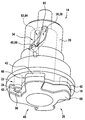
도 1에는 하우징(78) 및 인서트 공구(10)를 가진 전동 공구(12)를 포함한 전동 공구 시스템이 도시된다. 전동 공구(12)는 앵글 그라인더로서 형성된다. 인서트 공구(10)는 그라인딩 휠로서 형성된다. 인서트 공구(10)는 연결 장치(46)를 포함한다(도 4 참조). 연결 장치(46)는 연속 리세스(50)로서 형성된다.1 shows a power tool system including a
전동 공구(12)는 퀵 클램핑 장치를 포함한다. 퀵 클램핑 장치는 적어도 하나의 인서트 공구(10)를 전동 공구(12) 상에 배치하기 위해 제공된다. 전동 공구(12)는 퀵 클램핑 장치를 개방 및 폐쇄하기 위한 작동 수단(52)을 포함한다. 작동 수단(52)은 풀 레버(54)로서 형성된다. 풀 레버(54)는 편심체(74)를 포함한다. 작동 수단(52)은 특히 편심체(74)에 의해 퀵 클램핑 장치의 잠금 해제 볼트(76, 도 2 참조)를 축 방향으로 이동시키기 위해 제공된다. 잠금 해제 볼트(76)는 전동 공구(12)의 하우징(78) 내로 잠금 해제 볼트(76)의 이동시 퀵 클램핑 장치를 잠금 해제하기 위해 제공된다. 퀵 클램핑 장치가 잠금 상태일 때, 잠금 해제 볼트(76)는 전동 공구(12)의 하우징(78)으로부터 이동된다. 도 1에 도시된 작동 수단(52)은 폐쇄 상태에 있다. 전동 공구(12)는 구동 유닛(56)을 포함한다. 구동 유닛(56)은 인서트 공구(10)를 운동, 특히 회전시키기 위해 적어도 제공되는 운동 에너지를 적어도 제공하기 위해 제공된다. 구동 유닛(56)은 하우징(78) 내에 배치된다.The
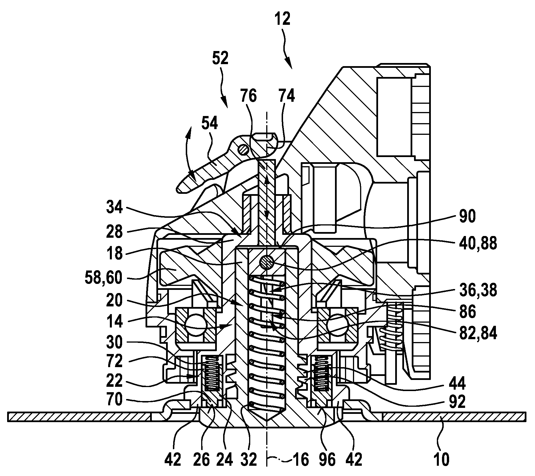
도 2에는 퀵 클램핑 장치가 중앙 단면도로 도시된다. 퀵 클램핑 장치는 출력 유닛(14)을 포함한다. 출력 유닛(14)은 출력 유닛(14)의 출력 축(16)을 중심으로 인서트 공구(10)를 이동시키기 위해 제공된다. 출력 유닛(14)은 출력 요소(28)를 포함한다. 출력 요소(28)는 원통형 중공 샤프트로서 형성된다. 출력 요소(28)는 출력 축(16)을 중심으로 센터링되어 배치된다.2, the quick clamping device is shown in a central sectional view. The quick clamping device comprises an
전동 공구(12)는 구동 유닛(56)에 의해 생성된 힘을 전달, 특히 수용하기 위한 힘 전달 요소(58)를 포함한다. 힘 전달 요소(58)는 링 기어(60)로서 형성된다. 링 기어(60)는 출력 요소(28)와 압력 끼워맞춤 방식으로 연결된다. 링 기어(60)는 당업자에게 통상적인 방법, 예를 들어 구동 피니언 및 구동 샤프트(도시되지 않음)에 의해 구동 유닛(56)과 연결된다. 링 기어(60)는 구동 유닛(56)에 의해 회전식으로 구동 가능하다.The
퀵 클램핑 장치는 고정 유닛(20)을 포함한다. 고정 유닛(20)은 인서트 공구(10)를 출력 유닛(14) 상에 축 방향으로 고정하기 위해 제공된다. 고정 유닛(20)은 고정 요소(18)를 포함한다. 고정 요소(18)는 출력 유닛(14), 특히 출력 요소(28) 상에 분실 방지 방식으로 배치되거나 및/또는 출력 유닛(14), 특히 출력 요소(28) 상에 탈착 불가능하게 조립된다. 고정 요소(18)는 잠금부(66)를 포함한다. 잠금부(66)는 고정 요소(18)와 일체형으로 형성된다. 잠금부(66)는 출력 축(16)을 따라서 볼 때 출력 유닛(14)으로부터 먼 하부면 상에 배치된다. 잠금부(66)는 각진 십자형의 윤곽(48)을 갖는다. 잠금부(66)는 출력 요소(28)와 잠금부(66) 사이에 인서트 공구(10)를 홀딩하기 위해 형상 끼워맞춤 결합을 형성하도록 제공된다.The quick clamping device includes a fixing
고정 유닛(20), 특히 고정 요소(18)는 나사산(44)을 포함한다. 고정 유닛(20)의 나사산(44)은 사다리꼴 나사산 또는 톱니 나사산으로서 형성된다. 고정 유닛(20)의 나사산(44)은 고정 요소(18)와 일체형으로 형성된다. 고정 유닛(20)의 나사산(44)은 외부 나사산으로서 형성된다. 출력 유닛(14)은 다른 나사산(92)을 포함한다. 다른 나사산(92)은 출력 요소(28)와 일체형으로 형성된다. 다른 나사산(92)은 내부 나사산으로서 형성된다. 다른 나사산(92)은 사다리꼴 나사산 또는 톱니 나사산으로서 형성된다. 고정 유닛(20)의 나사산(44)은 다른 나사산(92)에 대응한다.The fixing
고정 요소(18)는 이동 가능하게 지지된다. 고정 요소(18)는 출력 유닛(14)에 대해 출력 축(16)을 중심으로 이동 가능하게 지지된다. 고정 요소(18)는 출력 유닛(14)에 대해 출력 축(16)의 방향으로 이동 가능하게 지지된다. 퀵 클램핑 장치는 록킹 유닛(22)을 포함한다. 록킹 유닛(22)은 2 개의 록킹 요소들(24)을 포함한다. 록킹 요소(24)에 의해 고정 가능한 위치로부터 고정 요소(18)의 축 방향 최대 편향은 최대 10mm 이다. 고정 요소(18)의 축 방향 최대 편향은 나사산(44)의 피치 및/또는 다른 나사산(92)의 피치에 의해 미리 결정된다. 록킹 요소(24)는 이동 가능하게 지지된다. 록킹 요소(24)는 고정 요소(18)가 출력 축(16)을 중심으로 이동하는 것을 방지하기 위해 제공된다. 고정 요소(18)가 록킹 요소(24)에 의해 록킹되면, 록킹 요소(24)는 형상 끼워맞춤 결합에 의해 고정 요소(18)의 회전을 방지한다.The fixing
록킹 요소(24)는 접촉 면(26)을 포함한다. 접촉 면(26)은 고정 요소(18) 상에 접촉하도록 제공된다. 록킹 요소(24)는 축 방향 연장부(70)를 포함한다. 접촉 면(26)은 축 방향 연장부(70) 상에 배치된다. 록킹 요소(24)는 다른 접촉 면(96)을 포함한다. 다른 접촉 면(96)은 적어도 하나의 작동 상태에서 인서트 공구(10)에 접촉하도록 제공된다.The locking
록킹 요소(24)는 출력 유닛(14)의 출력 요소(28) 상에 이동 가능하게 지지된다. 록킹 요소(24)는 출력 요소(28)에 의해 한정된 슬리브(72) 내에 지지된다. 록킹 요소(24)는 슬리브(72) 내로 삽입 가능하게 그리고 슬리브(72)로부터 인출 가능하게 지지된다. 슬리브(72)는 출력 요소(28)와 일체형으로 형성된다. 록킹 유닛(22)은 적어도 하나의 록킹 스프링(30)을 포함한다. 록킹 유닛(22)의 각각의 록킹 요소(24)는 록킹 스프링(30)을 포함한다. 록킹 스프링(30)은 록킹 요소(24)에 록킹 위치의 방향으로 스프링력에 의한 예응력을 가한다. 도 2에 도시된 록킹 스프링은 클램핑된 상태이다. 록킹 스프링(30)에 의해, 록킹 요소(24)는 블록킹이 없으면 고정 요소(18)를 통해 슬리브(72)로부터 이동된다.The locking
고정 유닛(20)은 클램핑 스프링(32)을 포함한다. 고정 유닛(20), 특히 고정 요소(18)는 클램핑 스프링(32) 둘레를 그립핑한다. 클램핑 스프링(32)은 고정 유닛(20), 특히 고정 요소(18) 내에 배치된다. 클램핑 스프링(32)은 압축 스프링으로서 형성된다. 도 2에는 이완된 상태에서의 클램핑 스프링(32)이 도시된다. 클램핑 스프링(32)은 적어도 하나의 작동 상태(도 3 참조)에서 클램핑력을 발생시키고, 상기 클램핑력은 고정 요소(18)를 통한 전달에 의해 록킹 요소(24)의 접촉 면(26)에 가압력을 가한다. 록킹 요소(24)는 고정 요소(18)의 회전을 저지함으로써 적어도 하나의 작동 상태에서 클램핑 스프링(32)이 릴리즈되는 것을 방지한다.The fixing
퀵 클램핑 장치는 캠 메커니즘(34)을 포함한다. 캠 메커니즘(34)은 고정 요소(18)를 적어도 2 개의 단부 위치들 사이에서 왕복 이동시키기 위해 제공되며, 단부 위치들 중 하나는 록킹 유닛(22)에 의해 고정 가능한 위치이다. 캠 메커니즘(34)은 다수의 캠 메커니즘 요소들(38, 40, 82)을 포함한다.The quick clamping device includes a
출력 유닛(14)은 캠 메커니즘 요소(38)를 포함한다. 출력 유닛(14)의 캠 메커니즘 요소(38)는 출력 요소(28) 내의 리세스(36)로서 형성된다. 출력 유닛(14)의 캠 메커니즘 요소(38)는 출력 축(16)에 대해 각진 코스를 가진 경로 곡선(80)을 형성한다. 고정 유닛(20)은 캠 메커니즘 요소(82)를 포함한다. 고정 유닛(20)의 캠 메커니즘 요소(82)는 고정 요소(18) 내의 리세스(84)로서 형성된다. 고정 유닛(20)의 캠 메커니즘 요소(82)는 출력 축(16)에 대해 평행한 코스를 가진 경로 곡선(86)을 형성한다. 출력 유닛(14) 및 고정 유닛(20)의 캠 메커니즘 요소들(38, 82)과는 상이한 캠 메커니즘(34)의 캠 메커니즘 요소(40)는 이동 가능한 캠 메커니즘 요소(88)로서 형성된다. 캠 메커니즘(34)의 캠 메커니즘 요소(40), 특히 이동 가능한 캠 메커니즘 요소(88)는 고정 요소(18) 내에 적어도 부분적으로 배치된다. 캠 메커니즘(34)의 캠 메커니즘 요소(40), 특히 이동 가능한 캠 메커니즘 요소(88)는 축 방향으로 이동 가능하게 배치된다. 캠 메커니즘(34)의 캠 메커니즘 요소(40), 특히 이동 가능한 캠 메커니즘 요소(88)는 회전식으로 이동 가능하게 배치된다. 캠 메커니즘(34)의 캠 메커니즘 요소(40), 특히 이동 가능한 캠 메커니즘 요소(88)는 출력 유닛(14)의 캠 메커니즘 요소(38) 및/또는 고정 유닛(20)의 캠 메커니즘 요소(82) 내로 적어도 부분적으로 맞물린다. 캠 메커니즘(34)의 캠 메커니즘 요소(40), 특히 이동 가능한 캠 메커니즘 요소(88)는 적어도 하나의 작동 상태에서 잠금 해제 볼트(76)에 접촉하도록 제공된 접촉 면(90)을 포함한다.The
전동 공구(12)의 하우징(78) 내로의 잠금 해제 볼트(76)의 가압은 캠 메커니즘(34)의 캠 메커니즘 요소(40), 특히 이동 가능한 캠 메커니즘 요소(88)를 축 방향으로 편향시킨다. 이동 가능한 캠 메커니즘 요소(88)가 출력 유닛(14)의 캠 메커니즘 요소(38) 내로 맞물리게 접촉됨으로써, 이동 가능한 캠 메커니즘 요소(88)가 출력 유닛(14)의 캠 메커니즘 요소(38)의 각진 경로 곡선(80)을 따르고, 이는 이동 가능한 캠 메커니즘 요소(88)의 회전 운동을 일으킨다. 고정 유닛(20)의 캠 메커니즘 요소(82) 내로 맞물린 이동 가능한 캠 메커니즘 요소(88)의 회전 운동은 이동 가능한 캠 메커니즘 요소(88)와 출력 유닛(14) 사이에 배치된 고정 요소(18)를 회전시킨다.The pressing of the unlocking
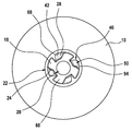
출력 유닛(14)은 적어도 하나의 토크 전달 요소(42)를 포함한다. 토크 전달 요소(42)는 출력 유닛(14)으로부터 인서트 공구(10)로 토크를 전달하기 위해 제공된다. 토크 전달 요소(42)는 출력 요소(28)와 일체형으로 형성된다. 토크 전달 요소(42)는 각진 십자 형태의 외부 윤곽(68)을 갖는다(도 3 참조). 토크 전달 요소(42)는 조립 상태에서 외부 윤곽(68)에 의해 인서트 공구(10)와의 형상 끼워맞춤 결합을 형성하기 위해 제공된다.The
토크 전달 요소(42)의 외부 윤곽(68)은 고정 요소(18)의 적어도 하나의 위치에서 고정 요소(18), 특히 고정 요소(18)의 잠금부(66)에 대해 합동으로 형성된다(도 3 참조). 토크 전달 요소(42)의 외부 윤곽(68)은 인서트 공구(10)의 적어도 하나의 위치에서 인서트 공구(10)의 연결 장치(46)와 합동으로 형성된다. 연결 장치(46), 특히 연결 장치(46)의 내부 윤곽(94)은 고정 요소, 특히 퀵 클램핑 장치의 잠금부(18)의 윤곽(48)에 대응하도록 형성된다.The
특히 클램핑 스프링(32)의 클램핑시, 이동 가능한 캠 메커니즘 요소(88)가 X의 경로만큼 이동하면 고정 요소(18)가 각도(α)만큼 회전하게 된다. 이 회전은 특히 나사산(44) 및/또는 다른 나사산(92)에 의해 나사산(44) 및/또는 다른 나사산(92)의 피치(S)에 따라 축 방향 편향을 야기한다. 따라서 축 방향 편향은 α/360°* S 이다. 클램핑 스프링(32)의 클램핑력 대 고정 요소(18)의 클램핑력의 전달비는 U = X * 360°* S/α이다. 이로써, 고정 요소(18)의 클램핑력은 클램핑 스프링(32)의 클램핑력보다 U배 더 크다.In particular, when clamping the clamping spring 32, when the movable cam mechanism element 88 moves by the path of X, the fixing
도시된 실시예에서, 이동 가능한 캠 메커니즘 요소(88)가 최대 편향된 경우 X = 11cm, α = 36° 및 S = 3mm이다. 도시된 실시예에서, 전달비는 값, U = 37을 갖는다.In the illustrated embodiment, the movable cam mechanism element 88 is X = 11 cm, α = 36 ° and S = 3 mm when the maximum deflection. In the illustrated embodiment, the transmission ratio has a value, U = 37.
10
인서트 공구
12
전동 공구
14
출력 유닛
16
출력 축
18
고정 요소
20
고정 유닛
22
록킹 유닛
24
록킹 요소
28
출력 요소
30
록킹 스프링
32
클램핑 스프링
34
캠 메커니즘
36
리세스
38
캠 메커니즘 요소
40
다른 캠 메커니즘 요소
42
토크 전달 요소
44
나사산
46
연결 장치
48
윤곽10 insert tools
12 Power tools
14 output units
16 output shaft
18 fixed elements
20 fixed units
22 locking unit
24 locking elements
28 output elements
30 locking spring
32 Clamping spring
34 cam mechanism
36 recess
38 cam mechanism elements
40 different cam mechanism elements
42 Torque transmission elements
44 Thread
46 Connecting devices
48 Configuration
Claims (14)
특히 이동 가능하게 지지된 적어도 하나의 록킹 요소(24)를 구비한 적어도 하나의 록킹 유닛(22)이 제공되고, 상기 록킹 요소(24)는 상기 출력 유닛(14)에 대해 적어도 상기 출력 축(16)을 중심으로 이동 가능하게 지지된 상기 고정 요소(18)가 상기 출력 축(16)을 중심으로 이동하는 것을 방지하기 위해 제공되는 것을 특징으로 하는 퀵 클램핑 장치. A quick clamping device for placing at least one insert tool (10) on a power tool (12), in particular an angle grinder, which moves the insert tool (10) about the output axis (16) of the output unit (14) The insert tool 10 is provided with at least one output unit 14 for carrying out, and at least one fixing element 18 which is particularly detachably assembled and movablely supported on the output unit 14. In the quick clamping device comprising at least one fixing unit (20) for fixing at least axially on the output unit (14),
In particular at least one locking unit 22 is provided with at least one locking element 24 movably supported, said locking element 24 being at least with respect to said output unit 14 at least the output shaft 16. Quick clamping device, characterized in that provided to prevent movement of the fixing element 18 is movably supported around the center about the output shaft (16).
Applications Claiming Priority (3)
| Application Number | Priority Date | Filing Date | Title |
|---|---|---|---|
| DE102017214117.4 | 2017-08-11 | ||
| DE102017214117.4A DE102017214117A1 (en) | 2017-08-11 | 2017-08-11 | Quick clamping device |
| PCT/EP2018/070744 WO2019030057A1 (en) | 2017-08-11 | 2018-07-31 | Quick clamping device |
Publications (2)
| Publication Number | Publication Date |
|---|---|
| KR20200039687A true KR20200039687A (en) | 2020-04-16 |
| KR102566069B1 KR102566069B1 (en) | 2023-08-14 |
Family
ID=63079923
Family Applications (1)
| Application Number | Title | Priority Date | Filing Date |
|---|---|---|---|
| KR1020207003870A KR102566069B1 (en) | 2017-08-11 | 2018-07-31 | quick clamping device |
Country Status (8)
| Country | Link |
|---|---|
| US (2) | US11607773B2 (en) |
| EP (1) | EP3664962A1 (en) |
| JP (1) | JP7101757B2 (en) |
| KR (1) | KR102566069B1 (en) |
| CN (2) | CN116021390A (en) |
| BR (1) | BR112020002420A2 (en) |
| DE (1) | DE102017214117A1 (en) |
| WO (1) | WO2019030057A1 (en) |
Families Citing this family (7)
| Publication number | Priority date | Publication date | Assignee | Title |
|---|---|---|---|---|
| CN211029451U (en) * | 2019-05-29 | 2020-07-17 | 南京德朔实业有限公司 | Electric tool |
| CN110394736B (en) * | 2019-07-10 | 2020-05-22 | 三明学院 | Large-scale abrasive wheel saw grinding wheel replacement system |
| DE102019218092A1 (en) * | 2019-11-22 | 2021-05-27 | Robert Bosch Gmbh | Electromagnetic actuator |
| CN111496847B (en) * | 2020-05-29 | 2023-10-31 | 郑州芯博科技发展有限公司 | Quick change assembly quality |
| DE112022002088T5 (en) * | 2021-06-08 | 2024-01-25 | Milwaukee Electric Tool Corporation | POWER TOOL WITH TOOL-LESS FASTENING SYSTEM |
| DE102022204599A1 (en) | 2021-11-30 | 2023-06-01 | Robert Bosch Gesellschaft mit beschränkter Haftung | Tool interface device, in particular application tool hub |
| DE102022200952A1 (en) | 2022-01-28 | 2023-08-03 | Robert Bosch Gesellschaft mit beschränkter Haftung | Tool interface device, application tool with a tool interface device and machine tool system with an application tool and a machine tool |
Citations (7)
| Publication number | Priority date | Publication date | Assignee | Title |
|---|---|---|---|---|
| KR890009540A (en) * | 1987-12-08 | 1989-08-02 | 한스 울프강 파인 | Portable Machine Tool |
| KR20020020725A (en) * | 2000-04-07 | 2002-03-15 | 클라우스 포스, 게오르그 뮐러 | Grinding machine tool support |
| EP2213419A1 (en) * | 2009-01-30 | 2010-08-04 | C. & E. Fein GmbH | Hand-held power tool with tensioning device for a tool |
| DE102010043190A1 (en) * | 2010-10-29 | 2012-05-03 | Robert Bosch Gmbh | Hand machine tool fixture |
| US20130180747A1 (en) * | 2011-07-26 | 2013-07-18 | Positec Power Tools (Suzhou) Co., Ltd | Power tool and operation method thereof |
| JP2013158879A (en) * | 2012-02-03 | 2013-08-19 | Makita Corp | Work tool |
| CN103596726A (en) * | 2011-06-06 | 2014-02-19 | 罗伯特·博世有限公司 | Clamping device for a hand-held power tool |
Family Cites Families (19)
| Publication number | Priority date | Publication date | Assignee | Title |
|---|---|---|---|---|
| JPS5898163U (en) * | 1981-12-25 | 1983-07-04 | 日本レヂボン株式会社 | Sponge grindstone mounting device |
| DE3405885C1 (en) * | 1984-02-18 | 1986-01-09 | C. & E. Fein Gmbh & Co, 7000 Stuttgart | Device for fastening a grinding wheel on the grinding spindle of a portable angle grinder |
| DE4432973B4 (en) * | 1994-09-16 | 2009-10-01 | Robert Bosch Gmbh | Electric hand tool with a spindle lock |
| JPH1193164A (en) | 1997-09-18 | 1999-04-06 | Seijiro Nishioka | Rotation drive concrete pile with end steel pipe cap |
| JP2000190198A (en) * | 1998-12-28 | 2000-07-11 | Nisshin Seisakusho:Kk | Adapter device for honing tool |
| DE19944564A1 (en) * | 1999-09-17 | 2001-03-22 | Bosch Gmbh Robert | Hand-held machine tool has click nut whose change ring can be operated by hand when working spindle is stationary to axially loosen clamping flange and release clamped tool |
| DE10017457A1 (en) * | 2000-04-07 | 2001-10-11 | Bosch Gmbh Robert | Grinder tool holder |
| DE10017981A1 (en) * | 2000-04-11 | 2001-10-25 | Bosch Gmbh Robert | Tool holder |
| DE10039739A1 (en) * | 2000-08-16 | 2002-02-28 | C & E Fein Gmbh & Co Kg | Power tool with quick release device |
| US7013987B2 (en) * | 2000-09-08 | 2006-03-21 | Black & Decker | Clutch assembly and clamp mechanism for rotary tool disc |
| DE10361810A1 (en) * | 2003-12-30 | 2005-07-28 | Robert Bosch Gmbh | Hand tool with clamping device |
| DE102004051031B3 (en) * | 2004-10-20 | 2006-04-27 | Ott-Jakob Gmbh & Co. Spanntechnik Kg | jig |
| DE102006001986A1 (en) * | 2006-01-16 | 2007-07-19 | Robert Bosch Gmbh | Clamping device for releasably securing a disc-shaped tool |
| JP4229146B2 (en) | 2006-06-30 | 2009-02-25 | カシオ計算機株式会社 | NAVIGATION DEVICE AND PROGRAM |
| US20100183364A1 (en) * | 2007-06-06 | 2010-07-22 | No Screw Ltd. | Attachment mechanism |
| CN102233537B (en) * | 2010-04-27 | 2015-03-11 | 南京德朔实业有限公司 | Hand-held power tool with quick clamping device for working element |
| US9067293B2 (en) | 2011-09-30 | 2015-06-30 | Robert Bosch Gmbh | Accessory clamp for a power tool |
| CN203092512U (en) * | 2012-12-29 | 2013-07-31 | 南京德朔实业有限公司 | Attachment clamping mechanism and power tool with attachment clamping mechanism |
| DE102013216535A1 (en) * | 2013-08-21 | 2015-02-26 | Robert Bosch Gmbh | Hand tools Tool holder module |
-
2017
- 2017-08-11 DE DE102017214117.4A patent/DE102017214117A1/en active Pending
-
2018
- 2018-07-31 CN CN202310259720.9A patent/CN116021390A/en active Pending
- 2018-07-31 BR BR112020002420-1A patent/BR112020002420A2/en unknown
- 2018-07-31 CN CN201880052074.6A patent/CN110997230B/en active Active
- 2018-07-31 WO PCT/EP2018/070744 patent/WO2019030057A1/en unknown
- 2018-07-31 KR KR1020207003870A patent/KR102566069B1/en active IP Right Grant
- 2018-07-31 EP EP18749353.1A patent/EP3664962A1/en active Pending
- 2018-07-31 US US16/627,651 patent/US11607773B2/en active Active
- 2018-07-31 JP JP2020507691A patent/JP7101757B2/en active Active
-
2023
- 2023-02-21 US US18/171,984 patent/US20230191556A1/en active Pending
Patent Citations (7)
| Publication number | Priority date | Publication date | Assignee | Title |
|---|---|---|---|---|
| KR890009540A (en) * | 1987-12-08 | 1989-08-02 | 한스 울프강 파인 | Portable Machine Tool |
| KR20020020725A (en) * | 2000-04-07 | 2002-03-15 | 클라우스 포스, 게오르그 뮐러 | Grinding machine tool support |
| EP2213419A1 (en) * | 2009-01-30 | 2010-08-04 | C. & E. Fein GmbH | Hand-held power tool with tensioning device for a tool |
| DE102010043190A1 (en) * | 2010-10-29 | 2012-05-03 | Robert Bosch Gmbh | Hand machine tool fixture |
| CN103596726A (en) * | 2011-06-06 | 2014-02-19 | 罗伯特·博世有限公司 | Clamping device for a hand-held power tool |
| US20130180747A1 (en) * | 2011-07-26 | 2013-07-18 | Positec Power Tools (Suzhou) Co., Ltd | Power tool and operation method thereof |
| JP2013158879A (en) * | 2012-02-03 | 2013-08-19 | Makita Corp | Work tool |
Also Published As
| Publication number | Publication date |
|---|---|
| RU2020109422A3 (en) | 2021-11-16 |
| US20230191556A1 (en) | 2023-06-22 |
| DE102017214117A1 (en) | 2019-02-14 |
| JP7101757B2 (en) | 2022-07-15 |
| US11607773B2 (en) | 2023-03-21 |
| WO2019030057A1 (en) | 2019-02-14 |
| EP3664962A1 (en) | 2020-06-17 |
| CN110997230B (en) | 2023-03-10 |
| RU2020109422A (en) | 2021-09-13 |
| CN116021390A (en) | 2023-04-28 |
| BR112020002420A2 (en) | 2020-07-28 |
| JP2020529336A (en) | 2020-10-08 |
| US20200156209A1 (en) | 2020-05-21 |
| CN110997230A (en) | 2020-04-10 |
| KR102566069B1 (en) | 2023-08-14 |
Similar Documents
| Publication | Publication Date | Title |
|---|---|---|
| KR20200039687A (en) | Quick clamping device | |
| US9486909B2 (en) | Clamping device for a hand-held power tool | |
| JP5349615B2 (en) | Machine Tools | |
| US9694428B2 (en) | Tool attachment for a hand-held machine tool | |
| US8317574B2 (en) | Power-driven hand tool with clamping fixture for a tool | |
| US9486887B2 (en) | Tool chucking device | |
| US20220388109A1 (en) | Quick Clamping Device | |
| EP2688715B1 (en) | Hand held power tool with locking rotatable handle | |
| US7503734B2 (en) | Drill chuck actuator | |
| JP2010089255A (en) | Hand-held type driving machine | |
| US9339904B2 (en) | Power tool with a clamping mechanism for clamping a tool | |
| US20150290830A1 (en) | Tool Coupling Device | |
| US20200094373A1 (en) | Quick-Clamping Device for a Portable Machine Tool | |
| CA2848189C (en) | Wrench for rotary tool | |
| KR101384516B1 (en) | Slip control function using magnetic torque screwdriver with a torque limit | |
| TWI746599B (en) | Clamping device for tools | |
| JP2013255949A (en) | Chuck device | |
| US20220097214A1 (en) | Screwdriver Tool with a Gear Ratio | |
| JP2013166251A (en) | Chain saw | |
| RU2793243C2 (en) | Quick clamp, working tool, processing machine and processing system | |
| GB2271736A (en) | Blade mounting device | |
| CN106826700B (en) | Kit for a hand-held power tool | |
| JP6160155B2 (en) | Spindle hand turning device for sewing machine | |
| JP2017222025A (en) | Drill chuck |
Legal Events
| Date | Code | Title | Description |
|---|---|---|---|
| E902 | Notification of reason for refusal | ||
| E701 | Decision to grant or registration of patent right | ||
| GRNT | Written decision to grant |