KR20200037961A - Attaching apparatus for film on glass using air - Google Patents
Attaching apparatus for film on glass using air Download PDFInfo
- Publication number
- KR20200037961A KR20200037961A KR1020180117391A KR20180117391A KR20200037961A KR 20200037961 A KR20200037961 A KR 20200037961A KR 1020180117391 A KR1020180117391 A KR 1020180117391A KR 20180117391 A KR20180117391 A KR 20180117391A KR 20200037961 A KR20200037961 A KR 20200037961A
- Authority
- KR
- South Korea
- Prior art keywords
- film
- unit
- glass plate
- air
- roller
- Prior art date
Links
Images


Classifications
-
- B—PERFORMING OPERATIONS; TRANSPORTING
- B29—WORKING OF PLASTICS; WORKING OF SUBSTANCES IN A PLASTIC STATE IN GENERAL
- B29C—SHAPING OR JOINING OF PLASTICS; SHAPING OF MATERIAL IN A PLASTIC STATE, NOT OTHERWISE PROVIDED FOR; AFTER-TREATMENT OF THE SHAPED PRODUCTS, e.g. REPAIRING
- B29C63/00—Lining or sheathing, i.e. applying preformed layers or sheathings of plastics; Apparatus therefor
- B29C63/02—Lining or sheathing, i.e. applying preformed layers or sheathings of plastics; Apparatus therefor using sheet or web-like material
-
- B—PERFORMING OPERATIONS; TRANSPORTING
- B29—WORKING OF PLASTICS; WORKING OF SUBSTANCES IN A PLASTIC STATE IN GENERAL
- B29C—SHAPING OR JOINING OF PLASTICS; SHAPING OF MATERIAL IN A PLASTIC STATE, NOT OTHERWISE PROVIDED FOR; AFTER-TREATMENT OF THE SHAPED PRODUCTS, e.g. REPAIRING
- B29C63/00—Lining or sheathing, i.e. applying preformed layers or sheathings of plastics; Apparatus therefor
- B29C63/0065—Heat treatment
-
- B—PERFORMING OPERATIONS; TRANSPORTING
- B29—WORKING OF PLASTICS; WORKING OF SUBSTANCES IN A PLASTIC STATE IN GENERAL
- B29C—SHAPING OR JOINING OF PLASTICS; SHAPING OF MATERIAL IN A PLASTIC STATE, NOT OTHERWISE PROVIDED FOR; AFTER-TREATMENT OF THE SHAPED PRODUCTS, e.g. REPAIRING
- B29C65/00—Joining or sealing of preformed parts, e.g. welding of plastics materials; Apparatus therefor
- B29C65/48—Joining or sealing of preformed parts, e.g. welding of plastics materials; Apparatus therefor using adhesives, i.e. using supplementary joining material; solvent bonding
- B29C65/4805—Joining or sealing of preformed parts, e.g. welding of plastics materials; Apparatus therefor using adhesives, i.e. using supplementary joining material; solvent bonding characterised by the type of adhesives
- B29C65/483—Reactive adhesives, e.g. chemically curing adhesives
- B29C65/4835—Heat curing adhesives
-
- B—PERFORMING OPERATIONS; TRANSPORTING
- B29—WORKING OF PLASTICS; WORKING OF SUBSTANCES IN A PLASTIC STATE IN GENERAL
- B29C—SHAPING OR JOINING OF PLASTICS; SHAPING OF MATERIAL IN A PLASTIC STATE, NOT OTHERWISE PROVIDED FOR; AFTER-TREATMENT OF THE SHAPED PRODUCTS, e.g. REPAIRING
- B29C66/00—General aspects of processes or apparatus for joining preformed parts
- B29C66/70—General aspects of processes or apparatus for joining preformed parts characterised by the composition, physical properties or the structure of the material of the parts to be joined; Joining with non-plastics material
- B29C66/74—Joining plastics material to non-plastics material
- B29C66/746—Joining plastics material to non-plastics material to inorganic materials not provided for in groups B29C66/742 - B29C66/744
- B29C66/7465—Glass
-
- B—PERFORMING OPERATIONS; TRANSPORTING
- B29—WORKING OF PLASTICS; WORKING OF SUBSTANCES IN A PLASTIC STATE IN GENERAL
- B29C—SHAPING OR JOINING OF PLASTICS; SHAPING OF MATERIAL IN A PLASTIC STATE, NOT OTHERWISE PROVIDED FOR; AFTER-TREATMENT OF THE SHAPED PRODUCTS, e.g. REPAIRING
- B29C66/00—General aspects of processes or apparatus for joining preformed parts
- B29C66/90—Measuring or controlling the joining process
- B29C66/91—Measuring or controlling the joining process by measuring or controlling the temperature, the heat or the thermal flux
- B29C66/914—Measuring or controlling the joining process by measuring or controlling the temperature, the heat or the thermal flux by controlling or regulating the temperature, the heat or the thermal flux
- B29C66/9141—Measuring or controlling the joining process by measuring or controlling the temperature, the heat or the thermal flux by controlling or regulating the temperature, the heat or the thermal flux by controlling or regulating the temperature
-
- G—PHYSICS
- G01—MEASURING; TESTING
- G01N—INVESTIGATING OR ANALYSING MATERIALS BY DETERMINING THEIR CHEMICAL OR PHYSICAL PROPERTIES
- G01N21/00—Investigating or analysing materials by the use of optical means, i.e. using sub-millimetre waves, infrared, visible or ultraviolet light
- G01N21/84—Systems specially adapted for particular applications
- G01N21/88—Investigating the presence of flaws or contamination
- G01N21/89—Investigating the presence of flaws or contamination in moving material, e.g. running paper or textiles
- G01N21/892—Investigating the presence of flaws or contamination in moving material, e.g. running paper or textiles characterised by the flaw, defect or object feature examined
Abstract
Description
본 발명은 에어를 이용하여 유리판에 필름을 부착하는 에어식 필름 부착장치에 관한 것으로, 더욱 상세하게는 온풍을 이용하여 접착제에 열을 가한 후, 고압의 냉풍을 이용하여 접착제를 경화시키면서 필름을 유리판에 부착시키는 에어식 필름 부착장치에 관한 것이다.The present invention relates to an air-type film attaching device for attaching a film to a glass plate using air, and more specifically, after applying heat to the adhesive using warm air, while curing the adhesive using a high-pressure cold air to make the film a glass plate. It relates to an air-type film attachment device to be attached to.
일반적으로 필름을 유리에 부착시키는 대표적인 방식으로 크게 건식(dry type)과 습식(wet type) 2가지 방식이 있다.In general, there are two main methods of attaching a film to glass, such as a dry type and a wet type.
그 중 건식의 경우 유리에 필름을 부착하는 과정에서 일부 영역에 공기가 잔존하여 기포가 생긴다. 따라서, 필름이 유리에 부착되지 않고 들뜨게 되어 효과적으로 부착되지 못하고 미관상 좋지 않은 문제가 있었다.In the case of dry type, air remains in some areas in the process of attaching the film to the glass, thereby forming bubbles. Therefore, there was a problem in that the film was not attached to the glass and was lifted up, so that it was not effectively attached and the appearance was not good.
반면, 습식의 경우 위와 같은 문제점을 해결하기 위해 유리에 필름을 부착하는 과정에서 필름과 유리 사이에 물을 공급하는데, 공급된 물은 필름 부착 과정에서 필름과 유리 사이에 기포가 발생하는 것을 방지한다.On the other hand, in the case of wet, water is supplied between the film and the glass in the process of attaching the film to the glass in order to solve the above problems, and the supplied water prevents air bubbles from forming between the film and the glass in the process of attaching the film. .
그러나 물을 이용하는 습식의 경우, 필름 부착 과정에서 작업자가 필름과 유리 사이에서 물을 제거하는 작업을 지속적으로 수행해야 하고, 공급된 물을 건조하는 추가 공정이 필요하다.However, in the case of wet using water, in the process of attaching the film, the worker must continuously remove water between the film and the glass, and an additional process of drying the supplied water is required.
따라서 필름을 습식으로 부착하는 경우에는 기포 발생이 억제되는 대신 작업자의 물 제거 및 건조 공정이 필요하여 필름이 부착된 유리를 생산하기 위한 시간 및 비용을 증가시키는 문제가 있었다.Therefore, when the film is wetly attached, the generation of bubbles is suppressed, and instead, the water removal and drying process of the worker is required, thereby increasing the time and cost for producing the glass to which the film is attached.
이에, 도 1과 같이 한국등록특허 제10-1095492호에서는 유리에 필름을 접착시키는 압착부(110), 필름에서 이형지를 분리후 압착부(110)로 이송하는 필름 이송부(120) 및 유리를 이송하는 유리 이송부(130)로 이루어진 필름 부착기(100)를 포함하는 구성을 제안하고 있다.Thus, as shown in FIG. 1, in Korean Patent Registration No. 10-1095492, the
특히, 도 2와 같이 이형지(103)가 박리된 필름(102)을 상하 한 쌍의 롤러(111, 112)로 이루어진 압착부(110)로 공급하여 유리에 부착시키기 이전에 스팀 공급부(140)를 이용하여 필름 접착면에 스팀을 분사한다.Particularly, as shown in FIG. 2, the
따라서, 위와 같은 필름 부착기(100)에서는 직접 물을 분사하는 대신 스팀을 분사함으로써 유리와 필름 사이에 기포가 발생하는 것을 방지하면서도 건조 시간을 월등히 단축시킬 수 있게 한다.Therefore, in the
그러나, 이상과 같은 한국등록특허 제10-1095492호에서 이용하는 스팀은 인위적으로 작은 입자의 물을 혼합시켜 분무하는 것으로, 여전히 물을 사용하므로 별도의 건조 시간이 필요한 문제가 있다.However, the steam used in Korean Patent Registration No. 10-1095492 as described above is to artificially mix and spray small particles of water, and still uses water, which requires a separate drying time.
또한, 스팀을 필름에 분사한 후 곧바로 압착 롤러를 이용하여 한번에 강한 힘을 가하여 유리 위에 필름을 부착하므로 필름이 유리와 어긋나게 부착되는 문제가 빈번히 발생한다.In addition, since the film is attached to the glass by applying a strong force at a time using a pressing roller immediately after spraying steam onto the film, a problem that the film is misaligned with the glass frequently occurs.
본 발명은 전술한 문제점을 해결하기 위한 것으로, 온풍을 이용하여 접착제에 열을 가한 후, 고압의 냉풍을 이용하여 접착제를 경화시키면서 필름을 유리판에 부착시키는 에어식 필름 부착장치를 제공하고자 한다.The present invention is to solve the above-mentioned problems, and after applying heat to the adhesive using warm air, it is intended to provide an air-type film attaching device for attaching a film to a glass plate while curing the adhesive using a high-pressure cold air.
이를 위해, 본 발명에 따른 에어식 필름 부착장치는 유리판에 필름을 부착하기 위한 필름 부착장치에 있어서, 상기 필름을 유리판의 상면에 압착하여 접합시키는 압착 롤러부와; 이송롤러의 상부에 상기 유리판을 올려 상기 압착 롤러부로 이송시키는 유리판 이송부와; 상기 필름에 부착되어 있던 이형지를 제거하면서 상기 필름만을 상기 압착 롤러부로 이송시키는 필름 이송부와; 상기 압착 롤러부의 상류측에 설치되되, 상기 필름의 접합면에 도포된 접착제에 온풍을 가하여 상기 접착제에 열을 가하는 온풍 분사부; 및 상기 압착 롤러부와 온풍 분사부 사이에 설치되되, 필름의 외측면을 향해 고압의 냉풍을 가하여 상기 필름을 유리판 위에 가압하는 냉풍 분사부;를 포함하는 것을 특징으로 한다.To this end, the air-type film attaching device according to the present invention comprises: a film attaching device for attaching a film to a glass plate, comprising: a crimping roller unit for compressing and bonding the film to an upper surface of the glass plate; A glass plate conveying part for putting the glass plate on the upper part of the conveying roller and transferring it to the pressing roller part; A film transfer unit for transferring only the film to the compression roller unit while removing the release paper attached to the film; A hot air jet unit installed on the upstream side of the compression roller unit and applying heat to the adhesive applied to the bonding surface of the film to apply heat to the adhesive; It is characterized in that it comprises; and installed between the compression roller portion and the warm air blowing portion, applying a high pressure cold air toward the outer surface of the film to press the film onto the glass plate.
이때, 상기 온풍 분사부의 노즐부는 상기 압착 롤러부가 있는 하류측을 향해 상향 경사지게 설치되어 상기 접착제에 열을 가하고, 상기 냉풍 분사부의 노즐부는 상기 온풍 분사부가 있는 상류측을 향해 하향 경사지게 설치되어 냉풍으로 상기 필름의 외측면을 빗자루로 쓸듯이 가압하고, 상기 접착제를 냉각시켜 상기 압착 롤러부에서 최종적으로 접착하기 이전에 예비적으로 접착시키는 것이 바람직하다.At this time, the nozzle portion of the warm air injection portion is installed to be inclined upward toward the downstream side with the compression roller portion to apply heat to the adhesive, and the nozzle portion of the cold air injection portion is installed to be inclined downward toward the upstream side where the warm air injection portion is installed to cool the air. It is preferable to press the outer surface of the film as if sweeping it with a broom, cool the adhesive, and preliminarily bond it before finally bonding it in the pressing roller portion.
또한, 상기 필름 접합면을 촬영하는 검사 카메라와; 상기 검사 카메라에서 촬영된 영상을 분석하여 상기 유리판과 필름 사이에 존재하는 기포의 개수 및 크기 중 어느 하나 이상을 검출하는 기포 검출부; 및 상기 기포 검출부의 검출값을 입력받아 상기 기포의 개수가 많거나 크기가 크면 상기 온풍 분사부로 공급되는 온풍 온도를 높이고, 상기 냉풍 분사부로 공급되는 냉풍의 세기를 증가시키는 컨트롤러;를 더 포함하는 것이 바람직하다.In addition, an inspection camera for photographing the film bonding surface; A bubble detection unit that analyzes an image captured by the inspection camera and detects any one or more of the number and size of bubbles existing between the glass plate and the film; And a controller configured to increase the temperature of the warm air supplied to the warm air injection unit and increase the intensity of the cold air supplied to the cold air injection unit when the number of the bubbles is large or large when receiving the detection value of the bubble detection unit. desirable.
또한, 상기 온풍 분사부의 상류측에 설치되되, 상류측을 향해 하향 경사지게 설치되어 이송중인 유리판에 고압 공기를 분사하여 가압함으로써, 상기 이송롤러에 의해 이송중인 유리판의 상하 진동을 억제하고 유리판 표면의 이물질을 제거하는 에어 가압부;를 더 포함하는 것이 바람직하다.In addition, it is installed on the upstream side of the warm air injection unit, and is installed inclined downward toward the upstream side, thereby injecting and pressurizing high-pressure air to the glass plate being transported, thereby suppressing up and down vibrations of the glass plate being transported by the transfer roller and foreign matter on the surface of the glass plate It is preferable to further include an air pressurizing portion for removing the.
또한, 상기 유리판 이송부는 상기 유리판의 폭 방향 좌우 양측에 각각 구비되어 상기 유리판의 양측면을 가압하는 가이드를 포함하되, 상기 가이드는 상기 유리판의 폭에 따라 상기 유리판을 향해 전후방으로 이동하여 위치가 조절되는 것이 바람직하다.In addition, the glass plate transfer portion is provided on both sides of the glass plate in the left and right sides in the width direction, and includes a guide for pressing both sides of the glass plate, wherein the guide is moved forward and backward toward the glass plate according to the width of the glass plate to adjust the position. It is preferred.
이상과 같은 본 발명은 온풍을 이용하여 접착제에 열을 가한 후, 고압의 냉풍을 이용하여 접착제를 경화시키면서 필름을 유리판에 부착시킨다. 따라서, 기포의 발생을 방지하면서도 필름 부착 후 별도의 건조 공정이 필요 없고, 고압 냉풍으로 예비로 접착하여 자세를 바로 잡은 후 압착 롤러로 최종적으로 견고한 접착이 이루어지게 한다.In the present invention as described above, after applying heat to the adhesive using warm air, the film is attached to the glass plate while curing the adhesive using a high-pressure cold air. Therefore, while preventing the generation of air bubbles, there is no need for a separate drying process after the film is attached, and it is pre-bonded with high-pressure cold air to correct the posture, and finally, a firm adhesion is achieved with a compression roller.
도 1은 종래 기술에 따른 필름 압착기를 나타낸 사시도이다.
도 2는 상기 도 1의 스팀 공급부를 나타낸 부분도이다.
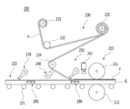
도 3은 본 발명에 따른 에어식 필름 부착장치를 나타낸 개략 구성도이다.
도 4는 본 발명에 따른 온풍 분사부와 냉풍 분사부를 나타낸 사시도이다.
도 5는 본 발명에 따른 검사부를 나타낸 도이다.
도 6은 상기 도 5에서의 기포 촬영 상태를 나타낸 도이다.
도 7은 본 발명에 따른 유리판 가이드를 나타낸 도이다.1 is a perspective view showing a film compactor according to the prior art.
FIG. 2 is a partial view showing the steam supply unit of FIG. 1.
3 is a schematic configuration diagram showing an air-type film attachment device according to the present invention.
Figure 4 is a perspective view showing a warm air injection unit and a cold air injection unit according to the present invention.
5 is a view showing an inspection unit according to the present invention.
6 is a view showing the bubble shooting state in FIG. 5.
7 is a view showing a glass plate guide according to the present invention.
이하, 첨부된 도면을 참조하여 본 발명의 바람직한 실시예에 따른 에어식 필름 부착장치에 대해 상세히 설명한다.Hereinafter, an air-type film attachment device according to a preferred embodiment of the present invention will be described in detail with reference to the accompanying drawings.
도 3과 같이, 본 발명에 따른 에어식 필름 부착장치(200)는 유리판(G)에 필름(F)을 부착하기 위한 것으로 압착 롤러부(210), 유리판 이송부(220), 필름 이송부(230), 온풍 분사부(240) 및 냉풍 분사부(250)를 포함한다. 3, the air-type
이때, 바람직한 다른 실시예로써 필름(F)의 부착 상태에 따라 온풍 분사부(240)와 냉풍 분사부(250)의 공기 온도 및 세기를 조절하도록 검사 카메라(261), 이미지 처리부(261a), 기포 검출부(262) 및 컨트롤러(263)를 더 포함한다.At this time, as another preferred embodiment, the
바람직한 또 다른 실시예로써 유리판 이송부(220)에 의해 유리판(G)이 이송시 이송 중의 진동 등에 의해 유리판(G)의 자세가 틀어지는 것을 방지하도록 에어 가압부(270) 및 가이드(280)를 더 포함한다.As another preferred embodiment, the glass plate (G) by the glass
위와 같은 구성으로 이루어진 본 발명의 에어식 필름 부착장치(200)는 온풍을 이용하여 필름(F)에 도포된 접착제에 열을 가한 후, 고압의 냉풍을 이용하여 접착제를 경화시키면서 필름(F)을 유리판(G)에 부착시킨다.The air-type
따라서, 접착면 기포의 발생을 방지하면서도 필름(F) 부착 후 별도의 건조 공정이 필요 없고, 고압 냉풍으로 예비로 접착하여 자세를 바로 잡은 후 압착 롤러부(210)에서 최종적으로 견고한 접착이 이루어지게 한다.Therefore, while preventing the generation of bubbles on the adhesive surface, there is no need for a separate drying process after attaching the film (F), and it is pre-bonded with high-pressure cold air to correct the posture, and finally, a firm adhesion is achieved in the
또한, 검사 카메라(261)로 촬영한 접착면 영상을 이미지 처리부(261a)에서 데이터처리 하고, 그 결과 기포가 검출된 경우에는 컨트롤러(263)에 의해 온풍 온도를 올려 접착제의 유동성을 높이고 냉풍 세기를 높여 압착력을 높인다.In addition, the image of the adhesive surface photographed by the
따라서, 유리판(G) 위에 접착되는 필름(F)의 부착력을 높이면서도 기포 발생을 억제하는 최적의 필름(F) 부착 환경을 자동으로 조성할 수 있게 한다. 아울러 에어 가압부(270) 및 가이드(280)에 의해 정자세가 유지되는 유리판(G)에 필름(F)이 정확히 부착되게 한다.Therefore, it is possible to automatically create an optimum film (F) attachment environment that suppresses the generation of bubbles while increasing the adhesion of the film (F) adhered to the glass plate (G). In addition, the film (F) is accurately attached to the glass plate (G) in which the posture is maintained by the air pressure unit (270) and the guide (280).
좀더 구체적으로 설명하면, 상기 압착 롤러부(210)는 필름(F)을 유리판(G)의 상면에 압착하여 접합시키는 것으로, 도시된 바와 같이 상부에 배치된 상부 압착 롤러(211) 및 그 하부에 배치된 하부 압착 롤러(212) 한 쌍으로 구성된다.In more detail, the
공지된 바와 같이 상부 압착 롤러(211)와 하부 압착 롤러(212) 사이의 간격은 유리판(G) 및 필름(F)의 두께에 따라 조절되며, 통상 상부 압착 롤러(211)를 승하강시켜 하부 압착 롤러(212) 사이의 상대적 간격을 조절한다.As is known, the spacing between the upper crimping
이때, 유리판(G)은 유리판 이송부(220)에 의해 투입되고, 동시에 필름(F)은 필름 이송부(230)에 의해 투입되며, 유리판(G) 위에 필름(F)이 적층된 상태에서 압착 롤러부(210) 사이를 통과하면 압착 및 접착이 이루어진다.At this time, the glass plate (G) is input by the glass
이러한 압착 롤러부(210)는 2차 압착부 혹은 최종 접착부에 해당하는 것으로, 후술하는 바와 같이 냉풍 분사부(250)에 의해 1차 압착 혹은 예비 접착된 후 후속의 압착 롤러부(210)에 제공된다.The
다음, 유리판 이송부(220)는 상술한 바와 같이 유리판(G)을 접착이 이루어지는 압착 롤러부(210)로 이송하기 위한 것으로, 일 예로 이송롤러(221) 위에 유리판(G)을 올려놓은 상태에서 롤러 회전으로 이송이 이루어지게 한다.Next, the glass
상기한 이송롤러(221)는 유리판(G)의 이송 방향에 대해 수직한 좌우 양측의 폭 방향에 각각 배치된 베이스 프레임을 따라 일정 간격으로 이송롤러(221)를 설치한 것이 적용될 수 있다. The above-described
이때, 다수의 이송롤러(221) 중 적어도 하나 이상은 모터에 연결된 구동롤러가 적용될 수 있으며, 구동롤러에 연결된 체인으로 모든 이송롤러(221)를 동시에 구동시킬 수 있다.At this time, at least one or more of the plurality of
또한 위와 같은 이송롤러(221)에 컨베이어 벨트(conveyor belt)를 장착하여 이송롤러(221)에 의해 무한궤도를 따라 회전하는 컨베이어 벨트 위에 유리판(G)을 올려놓은 상태에서 유리판(G)을 이송할 수도 있다.In addition, a conveyor belt is mounted on the
필름 이송부(230)는 필름(F)에 부착되어 있던 이형지(박리지)(P)를 제거하면서 필름(F)만을 압착 롤러부(210)로 이송시키는 것으로, 일 예로 공급롤러(231), 제1 텐션롤러(232), 권취롤러(233) 및 제2 텐션롤러(234)를 포함한다.The
이때, 공급롤러(231)에는 필름(F)에 이형지(P)가 합지된 상태로 감겨있어서 공급롤러(231)에 감겨있던 필름(F)이 풀리면서 이형지(P)가 제거된 후 유리판(G)에 부착되는 필름(F)만 압착 롤러로 공급된다.At this time, the
특히, 이형지(P)가 제거된 후 공급되는 필름(F)은 접착제가 도포되어 있는 접합면이 유리판(G)을 바라보는 방향(예: 도면 기준 하방)으로 공급되고, 이때 접합면은 후술할 온풍 분사부(240)에 노출된다.Particularly, the film (F) supplied after the release paper (P) is removed is supplied in a direction in which the adhesive-coated adhesive surface faces the glass plate (eg, below the drawing), where the bonding surface will be described later. It is exposed to the
한편, 제1 텐션롤러(232)는 필름(F)에서 분리된 이형지(P)에 장력을 가하도록 가압하는 위치에 설치되고, 권취롤러(233)는 제1 텐션롤러(232)에 의해 안내된 이형지(P)를 권취하여 회수한다. 이를 위해 제1 텐션롤러(232)와 권취롤러(233)는 이형지(P)에 장력을 가하는 위치로 적절히 조정된다.On the other hand, the
제2 텐션롤러(234)는 이형지(P)가 분리된 필름(F)이 압착 롤러부(210)로 이송되는 동안 장력을 가하도록 설치된다. 예컨대 제2 텐션롤러(234)는 공급롤러(231)에서 풀린 필름(F) 중 접착제가 묻지 않은 외측면을 가압하여 방향 전환이 이루어진 후 공급되게 한다.The
다음, 온풍 분사부(240)는 후술하는 냉풍 분사부(250)와 함께 필름(F)이 유리판(G)에 예비적으로 접착되도록 하며 아울러 물이나 스팀 대신 에어(air)를 사용하므로 별도의 건조 공정을 불필요하게 하는 핵심 구성이다.Next, the
이를 위해 온풍 분사부(240)는 압착 롤러부(210)의 상류측에 설치되어 필름(F) 접착 이전에 작용하고, 노즐부가 필름(F) 중 접착제가 도포된 접착면 향하도록 설치된다. 따라서, 필름(F)의 접합면에 도포된 접착제에 온풍을 가하여 접착제에 열을 가한다.To this end, the hot
도 4의 (a)와 같이 온풍 분사부(240)는 일 예로 내부에 공기가 유동하는 유로가 형성된 온풍관(241)과, 상기 온풍관(241)의 일측에 구비된 노즐부(242) 및 상기 온풍관(241)으로 설정된 온도의 온풍을 공급하는 온풍 공급기(243)를 포함한다.As shown in FIG. 4 (a), the warm
이때 노즐부(242)는 별도의 노즐을 다수개 설치할 있지만 도시된 바와 같이 온풍관(241)의 일측을 연속으로 절개 및 개방시켜 형성시킬 수 있으며, 노즐부(242)는 필름(F)의 접합면을 바라보도록 설치된다. At this time, the
온풍 공급기(243)는 압축기에 의해 단열압축되거나 별도의 히터를 이용하여 가열된 고온의 공기를 공급하는 것으로, 호스 및 밸브를 통해 온풍관(241)에 연결됨으로써 온풍관(241)에 공급된 온풍이 노즐부(242)를 통해 분출된다.The
따라서, 필름(F)에 도포되어 있던 접착제는 온풍에 의해 녹아 점도가 높아지게 되고, 점도가 높아진 접착제가 종래의 물이나 스팀 역할을 대신하므로 기포가 없는 필름(F) 부착이 가능하면서도 물이나 스팀을 건조하는 과정을 생략하게 한다.Therefore, the adhesive applied to the film (F) is melted by warm air to increase the viscosity, and the adhesive with the increased viscosity replaces the role of conventional water or steam. Let the drying process be omitted.
다만, 온풍 온도는 필름(F)에 도포된 접착제 종류 및 필름(F) 부착 장소의 온도 등을 고려하여 적정한 온도를 설정하는 것이 바람직하다. 즉, 온도가 너무 높으면 접착제의 액화가 진행되어 흘러내리고, 온도가 너무 낮으면 위와 같이 접착 특성을 향상시키기 어려우므로 적정 온도를 설정한다.However, it is preferable to set an appropriate temperature in consideration of the type of adhesive applied to the film F and the temperature of the place where the film F is attached. That is, if the temperature is too high, the liquefaction of the adhesive proceeds and flows down, and if the temperature is too low, it is difficult to improve the adhesive properties as described above, so an appropriate temperature is set.
다음, 냉풍 분사부(250)는 상술한 온풍 분사부(240)에서 분사된 온풍에 의해 가열된 필름(F)을 냉각시킴과 동시에 필름(F)을 고압으로 가압하여 유리판(G)에 필름(F)을 예비적으로 부착시킨다.Next, the cold
이를 위해 냉풍 분사부(250)는 상술한 압착 롤러부(210)와 온풍 분사부(240) 사이에 설치되되, 필름(F)의 외측면을 향해 고압의 냉풍을 가하여 필름(F)이 유리판(G) 위에 가압 및 접착되게 한다.To this end, the cold
도 4의 (b)와 같이 냉풍 분사부(250)는 상술한 온풍 분사부(240)와 유사하게 내부에 공기가 유동하는 유로가 형성된 냉풍관(251)과, 상기 냉풍관(251)의 일측에 구비된 노즐부(252) 및 상기 냉풍관(251)으로 설정된 온도의 온풍을 공급하는 냉풍 공급기(253)를 포함한다.As shown in FIG. 4 (b), the cold
즉, 냉풍 분사부(250)는 온풍 분사부(240)와 다르게 저온의 냉풍을 분사하는 점에서 차이가 있다. 냉풍 공급을 위해 겨울철에는 외기를 도입할 있고 여름철에는 히트펌프 등을 이용할 수 있다. That is, the cold
특히 온풍 분사부(240)는 노즐부(242)의 개구가 비교적 넓어서 약한 바람을 불어 필름(F)의 흔들림을 억제함에 비해, 냉풍 분사부(250)는 강한 바람으로 필름(F)을 냉각 및 가압하여 온풍에 의해 가열된 접착제를 경화시킴과 동시에 필름(F)이 부착되게 한다.In particular, the warm
또한 온풍 분사부(240)의 노즐부(242)는 압착 롤러부(210)가 있는 하류측을 바라보되 상향 경사지게 설치되어 필름(F)에 도포된 접착제에 열을 가함에 반해, 냉풍 분사부(250)의 노즐부(252)는 온풍 분사부(240)가 있는 상류측을 바라보되 하향 경사지게 설치된다.In addition, the
따라서, 냉풍 분사부(250)의 냉풍으로 필름(F)의 외측면(접착면의 반대면)을 빗자루로 쓸듯이 가압하고, 가열되었던 접착제를 냉각시켜 압착 롤러부(210)에서 최종적으로 접착하기 이전에 예비적으로 접착되게 한다.Therefore, the outer surface of the film (F) with the cold air of the cold air injection unit 250 (opposite side of the adhesive surface) is swept with a broom, and the heated adhesive is cooled to finally bond in the
이를 통해 냉풍 분사부(250)에서 유리판(G)의 정위치에 매칭되도록 필름(F)을 예비적으로 접착한 후, 후속의 압착 롤러부(210)에 의해 강한 힘으로 최종적으로 부착이 이루어지므로, 기포 등의 발생을 억제하면서도 정확한 부착을 가능하게 한다.Through this, after the film F is preliminarily adhered to match the correct position of the glass plate G in the cold
한편, 도 5와 같이, 본 발명은 온풍과 냉풍이 접합면에 미치는 영향을 분석하여 최적의 필름(F) 접합 상태로 조정할 수 있도록 검사 카메라(261)와, 이미지 처리부(261a)와, 기포 검출부(262) 및 컨트롤러(263)를 포함한다.On the other hand, as shown in Figure 5, the present invention analyzes the effect of the hot air and cold air on the bonding surface to adjust to the optimal film (F) bonding
이를 위해 검사 카메라(261)는 유리와 필름(F)의 접합면을 촬영한다. 접합면은 바람직하게 예비 접착이 이루어진 후 압착 롤러부(210)에 의해 최종적으로 부착이 이루어지기 이전에 검사를 하는 것이 바람직하다.To this end, the
본 발명은 압착 롤러부(210) 이후에 검사를 하여 압착 롤러부(210)의 영향까지 고려할 수 있지만, 바람직하게는 온풍 분사부(240)와 냉풍 분사부(250)에 의한 영향만을 고려하기 위해 냉풍 분사부(250)와 압착 롤러부(210) 사이에 검사 카메라(261)를 설치한다.In the present invention, the influence of the
위와 같이 검사 카메라(261)에 의해 필름(F) 접합면을 촬영한 이후에는, 촬영된 접합면에 대한 영상 데이터를 이미지 처리부(261a)에 제공하고, 이미지 처리부(261a)는 영상 처리를 한다. 영상처리는 기포를 검출하기 적합한 방식을 이용한다.After the film (F) bonding surface is photographed by the
도 6과 같이, 기포 검출부(262)는 검사 카메라(261)에서 촬영된 영상을 분석하여 유리판(G)과 필름(F) 사이에 존재하는 기포의 개수 및 크기 중 어느 하나 이상을 검출한다. 즉, 접합면에 기포가 많은지 혹은 기포가 적더라도 크기가 큰지 검출하며, 필요에 따라서는 이들 모두를 검출한다.As shown in FIG. 6, the
기포 검출을 분석하는 영상 분석 기법으로는 다양한 것이 있지만 대표적으로는 기포가 있는 부분이 다른 접합면보다 흰색으로 보이는 점을 이용하여, 검은 색과 흰색의 경계 수나 경계 면적을 분석하여 검출할 수 있다.Although there are various image analysis techniques for analyzing bubble detection, representatively, it is possible to detect by analyzing the number of borders or the boundary area between black and white by using a point where the bubbled portion is whiter than the other joint surface.
컨트롤러(263)는 기포 검출부(262)의 검출값을 입력받아 기포의 개수가 많거나 크기가 크면 온풍 분사부(240)로 공급되는 온풍 온도를 높이고, 냉풍 분사부(250)로 공급되는 냉풍의 세기를 증가시킨다.When the number of bubbles is large or large, the
온풍 온도와 냉풍의 세기는 온풍 공급기(243) 및 냉풍 공급기(253)를 제어하여 조절이 가능하며, 온풍 온도를 높이면 접착제를 더 가열하여 점도를 더욱 높이고, 냉풍 세기를 늘리면 가압력을 증가한다.The temperature of the hot air and the intensity of the cold air can be controlled by controlling the
물론, 본 발명은 위와 같은 조절에 한정하는 것은 아니고, 기포의 분포도, 접착면 중 발생위치 등을 더 고려하고, 기포의 개수 및 크기도 더욱 세밀하게 분류하여 온풍 온도와 냉풍 세기를 낮추는 등의 다른 조절도 가능하다.Of course, the present invention is not limited to the above control, and further considers the distribution of air bubbles, the location of occurrence on the adhesive surface, etc., and further classifies the number and size of air bubbles to lower the warm air temperature and cold air intensity. Adjustment is also possible.
나아가, 에어 가압부(270)는 유리판(G)의 흔들림을 방지하기 위한 것으로, 온풍 분사부(240)에서의 온풍 분사 및 냉풍 분사부(250)에서의 압착을 방해하지 않도록 온풍 분사부(240)의 상류측에서 그 분사측이 하향 경사지게 설치된다.Furthermore, the
따라서, 이송중인 유리판(G)에 고압 공기를 분사하여 가압함으로써, 이송롤러(221)에 의한 유리판(G)의 상하 진동을 억제한다. 또한, 접합이 이루어지는 측의 반대 방향으로 에어를 쏴서 유리판(G) 표면에 묻은 먼지 등 이물질을 제거한다.Therefore, by injecting and pressurizing high-pressure air to the glass plate G being transported, the vertical vibration of the glass plate G by the
도 7과 같이, 가이드(280)는 상술한 유리판 이송부(220)에 설치되는 것으로, 유리판(G)의 폭 방향 좌우 양측에 각각 구비되어 상기 유리판(G)의 양측면을 가압한다.As shown in FIG. 7, the
즉, 도 1에서 살펴본 바와 같이 유리판 이송부(220)에는 적어도 한 개소 이상에 유리판(G)의 측면을 가압하는 가이드(280)가 구비되어 일정 간격마다 유리판(G)을 직선 이동을 안내한다.That is, as shown in FIG. 1, the glass
이때 가이드(280)가 다른 장치들 사이에 설치되는 경우에는 해당 장치들의 작동을 방해하지 않도록 유리판(G)의 두께 보다 낮은 위치에 설치되어 유리판(G)의 상면 위로 돌출되지 않게 한다.At this time, when the
또한, 가이드(280)는 유리판(G)의 폭에 따라 조절이 가능하도록 유리판(G)을 향해 전후방으로 이동하여 위치가 조절된다. 가이드(280)의 작동은 실린더나 각종 기어 어셈블리를 통해 구현이 가능하며, 가급적 좌우 양측의 가이드(280)가 동시 작동되도록 연동시킨다.In addition, the position of the
이상, 본 발명의 특정 실시예에 대하여 상술하였다. 그러나, 본 발명의 사상 및 범위는 이러한 특정 실시예에 한정되는 것이 아니라 본 발명의 요지를 변경하지 않는 범위 내에서 다양하게 수정 및 변형이 가능하다는 것을 본 발명이 속하는 기술 분야에서 통상의 지식을 가진 자라면 이해할 것이다.In the above, specific examples of the present invention have been described above. However, the spirit and scope of the present invention is not limited to these specific embodiments, and various modifications and variations are possible within a range that does not change the gist of the present invention. If you grow up, you will understand.
따라서, 이상에서 기술한 실시예들은 본 발명이 속하는 기술 분야에서 통상의 지식을 가진 자에게 발명의 범주를 완전하게 알려주기 위해 제공되는 것이므로, 모든 면에서 예시적인 것이며 한정적이 아닌 것으로 이해해야만 하며, 본 발명은 청구항의 범주에 의해 정의될 뿐이다.Therefore, the above-described embodiments are provided to completely inform the scope of the invention to those skilled in the art to which the present invention pertains, and should be understood as illustrative in all respects and not restrictive. The invention is only defined by the scope of the claims.
210: 압착 롤러부
220: 유리판 이송부
230: 필름 이송부
240: 온풍 분사부
250: 냉풍 분사부
261: 검사 카메라
261a: 이미지 처리부
262:기포 검출부
263: 컨트롤러
270: 에어 가압부
280: 가이드
G: 유리판
F: 필름
P: 이형지210: crimping roller portion
220: glass plate transfer unit
230: film transfer unit
240: warm air jet
250: cold air jet
261: inspection camera
261a: image processing unit
262: bubble detection unit
263: controller
270: air pressure
280: Guide
G: Glass plate
F: film
P: Hyungji Lee
Claims (5)
상기 필름(F)을 유리판(G)의 상면에 압착하여 접합시키는 압착 롤러부(210)와;
이송롤러(221)의 상부에 상기 유리판(G)을 올려 상기 압착 롤러부(210)로 이송시키는 유리판 이송부(220)와;
상기 필름(F)에 부착되어 있던 이형지(P)를 제거하면서 상기 필름(F)만을 상기 압착 롤러부(210)로 이송시키는 필름 이송부(230)와;
상기 압착 롤러부(210)의 상류측에 설치되되, 상기 필름(F)의 접합면에 도포된 접착제에 온풍을 가하여 상기 접착제에 열을 가하는 온풍 분사부(240); 및
상기 압착 롤러부(210)와 온풍 분사부(240) 사이에 설치되되, 필름(F)의 외측면을 향해 고압의 냉풍을 가하여 상기 필름(F)을 유리판(G) 위에 가압하는 냉풍 분사부(250);를 포함하는 것을 특징으로 하는 에어식 필름 부착장치.In the film (F) attachment device for attaching the film (F) to the glass plate (G),
A crimping roller portion 210 for crimping and bonding the film F to the upper surface of the glass plate G;
A glass plate conveying unit 220 for raising the glass plate G on the upper portion of the conveying roller 221 and transferring it to the crimping roller unit 210;
And while removing the release paper (P) attached to the film (F), the film transfer unit 230 for transferring only the film (F) to the compression roller unit 210;
A hot air jet unit 240 installed on the upstream side of the compression roller unit 210 and applying heat to the adhesive applied to the bonding surface of the film F to heat the adhesive; And
It is installed between the crimping roller unit 210 and the hot air jet unit 240, the cold air jet unit that pressurizes the film (F) onto the glass plate (G) by applying high pressure cold air toward the outer surface of the film (F) 250); Air-type film attachment device comprising a.
상기 온풍 분사부(240)의 노즐부(242)는 상기 압착 롤러부(210)가 있는 하류측을 향해 상향 경사지게 설치되어 상기 접착제에 열을 가하고,
상기 냉풍 분사부(250)의 노즐부(242)는 상기 온풍 분사부(240)가 있는 상류측을 향해 하향 경사지게 설치되어 냉풍으로 상기 필름(F)의 외측면을 빗자루로 쓸듯이 가압하고, 상기 접착제를 냉각시켜 상기 압착 롤러부(210)에서 최종적으로 접착하기 이전에 예비적으로 접착시키는 것을 특징으로 하는 에어식 필름 부착장치.According to claim 1,
The nozzle unit 242 of the warm air jet unit 240 is installed to be inclined upward toward the downstream side where the crimping roller unit 210 is applied to heat the adhesive,
The nozzle unit 242 of the cold air injection unit 250 is installed to be inclined downward toward the upstream side where the warm air injection unit 240 is located, and presses the outer surface of the film (F) with cold air as if sweeping the air. The air-type film attachment device characterized in that the adhesive is cooled and preliminarily adhered before the final adhesion in the compression roller part (210).
상기 필름(F) 접합면을 촬영하는 검사 카메라(261)와;
상기 검사 카메라(261)에서 촬영된 영상을 분석하여 상기 유리판(G)과 필름(F) 사이에 존재하는 기포의 개수 및 크기 중 어느 하나 이상을 검출하는 기포 검출부(262); 및
상기 기포 검출부(262)의 검출값을 입력받아 상기 기포의 개수가 많거나 크기가 크면 상기 온풍 분사부(240)로 공급되는 온풍 온도를 높이고, 상기 냉풍 분사부(250)로 공급되는 냉풍의 세기를 증가시키는 컨트롤러(263);를 더 포함하는 것을 특징으로 하는 에어식 필름 부착장치.According to claim 2,
An inspection camera 261 photographing the bonding surface of the film (F);
A bubble detection unit 262 that analyzes an image photographed by the inspection camera 261 and detects any one or more of the number and size of bubbles existing between the glass plate G and the film F; And
When the detection value of the bubble detection unit 262 is received, if the number of bubbles is large or large, the temperature of the warm air supplied to the warm air injection unit 240 is increased, and the intensity of cold air supplied to the cold air injection unit 250 is increased. Controller for increasing the (263); Air-type film attachment device further comprising a.
상기 온풍 분사부(240)의 상류측에 설치되되, 상류측을 향해 하향 경사지게 설치되어 이송중인 유리판(G)에 고압 공기를 분사하여 가압함으로써, 상기 이송롤러(221)에 의해 이송중인 유리판(G)의 상하 진동을 억제하고 유리판(G) 표면의 이물질을 제거하는 에어 가압부(270);를 더 포함하는 것을 특징으로 하는 에어식 필름 부착장치.The method according to any one of claims 1 to 3,
It is installed on the upstream side of the warm air blowing unit 240, and is installed inclined downward toward the upstream side, thereby injecting and pressurizing high-pressure air to the glass plate G being transported, so that the glass plate G being transported by the transport roller 221 Air suppression unit for suppressing the up and down vibration of the glass plate (G) to remove foreign substances on the surface; air-type film attachment device further comprising a.
상기 유리판 이송부(220)는 상기 유리판(G)의 폭 방향 좌우 양측에 각각 구비되어 상기 유리판(G)의 양측면을 가압하는 가이드(280)를 포함하되, 상기 가이드(280)는 상기 유리판(G)의 폭에 따라 상기 유리판(G)을 향해 전후방으로 이동하여 위치가 조절되는 것을 특징으로 하는 에어식 필름 부착장치.
According to claim 4,
The glass plate conveying unit 220 includes guides 280 provided on both sides of the glass plate G in the width direction left and right, and pressing both sides of the glass plate G, wherein the guide 280 is the glass plate G Air film attachment device, characterized in that the position is adjusted by moving forward and backward toward the glass plate (G) according to the width of the.
Priority Applications (1)
| Application Number | Priority Date | Filing Date | Title |
|---|---|---|---|
| KR1020180117391A KR102124532B1 (en) | 2018-10-02 | 2018-10-02 | Attaching apparatus for film on glass using air |
Applications Claiming Priority (1)
| Application Number | Priority Date | Filing Date | Title |
|---|---|---|---|
| KR1020180117391A KR102124532B1 (en) | 2018-10-02 | 2018-10-02 | Attaching apparatus for film on glass using air |
Publications (2)
| Publication Number | Publication Date |
|---|---|
| KR20200037961A true KR20200037961A (en) | 2020-04-10 |
| KR102124532B1 KR102124532B1 (en) | 2020-06-18 |
Family
ID=70291858
Family Applications (1)
| Application Number | Title | Priority Date | Filing Date |
|---|---|---|---|
| KR1020180117391A KR102124532B1 (en) | 2018-10-02 | 2018-10-02 | Attaching apparatus for film on glass using air |
Country Status (1)
| Country | Link |
|---|---|
| KR (1) | KR102124532B1 (en) |
Cited By (7)
| Publication number | Priority date | Publication date | Assignee | Title |
|---|---|---|---|---|
| CN111605176A (en) * | 2020-05-21 | 2020-09-01 | 广州碧沃电子科技有限公司 | Aluminum alloy sticking film machine |
| CN114701156A (en) * | 2022-04-03 | 2022-07-05 | 浙江博得新材料科技有限公司 | Plastic product is with surface pad pasting machine with preheat function |
| CN114919792A (en) * | 2022-06-01 | 2022-08-19 | 中迪机器人(盐城)有限公司 | Steel belt film sticking abnormity detection system and method |
| CN115008792A (en) * | 2022-03-31 | 2022-09-06 | 武汉大学 | Functional film attaching method based on air jet |
| KR20230109919A (en) * | 2022-01-14 | 2023-07-21 | 이동주 | Device and Method for Taping Liquid Crystal-Protective Tempered Glass on a Jig |
| CN117405677A (en) * | 2023-12-14 | 2024-01-16 | 常州树杰塑业有限公司 | Plastic film crack detection device |
| CN117681435A (en) * | 2024-01-30 | 2024-03-12 | 江西赣悦新材料有限公司 | Film pasting device for photovoltaic glass processing production |
Families Citing this family (1)
| Publication number | Priority date | Publication date | Assignee | Title |
|---|---|---|---|---|
| KR102540041B1 (en) * | 2020-05-25 | 2023-06-05 | (주)피엔피 | Detecting method of ultra thin glass using image sensor |
Citations (7)
| Publication number | Priority date | Publication date | Assignee | Title |
|---|---|---|---|---|
| JP2008132660A (en) * | 2006-11-28 | 2008-06-12 | Fujifilm Corp | Cooling device for attached substrate |
| KR101095492B1 (en) | 2009-09-03 | 2011-12-19 | 조찬제 | Film attaching apparatus |
| KR20120062972A (en) * | 2010-12-07 | 2012-06-15 | 아프로시스템 주식회사 | Light guide plate manufacturing system and method |
| KR101270943B1 (en) | 2013-01-04 | 2013-06-11 | 권용진 | Tinted film for attaching room type cleaning devices and methods using tinted film |
| JP2015089647A (en) * | 2013-11-06 | 2015-05-11 | 三菱重工業株式会社 | Prepreg sheet automatic lamination apparatus and prepreg sheet lamination method |
| KR20150124481A (en) * | 2014-04-28 | 2015-11-06 | 주식회사 넥스트아이 | Polaroid film examination machine |
| WO2018173618A1 (en) * | 2017-03-22 | 2018-09-27 | 東レ株式会社 | Method for producing prepreg and method for producing fiber-reinforced composite material |
-
2018
- 2018-10-02 KR KR1020180117391A patent/KR102124532B1/en active IP Right Grant
Patent Citations (7)
| Publication number | Priority date | Publication date | Assignee | Title |
|---|---|---|---|---|
| JP2008132660A (en) * | 2006-11-28 | 2008-06-12 | Fujifilm Corp | Cooling device for attached substrate |
| KR101095492B1 (en) | 2009-09-03 | 2011-12-19 | 조찬제 | Film attaching apparatus |
| KR20120062972A (en) * | 2010-12-07 | 2012-06-15 | 아프로시스템 주식회사 | Light guide plate manufacturing system and method |
| KR101270943B1 (en) | 2013-01-04 | 2013-06-11 | 권용진 | Tinted film for attaching room type cleaning devices and methods using tinted film |
| JP2015089647A (en) * | 2013-11-06 | 2015-05-11 | 三菱重工業株式会社 | Prepreg sheet automatic lamination apparatus and prepreg sheet lamination method |
| KR20150124481A (en) * | 2014-04-28 | 2015-11-06 | 주식회사 넥스트아이 | Polaroid film examination machine |
| WO2018173618A1 (en) * | 2017-03-22 | 2018-09-27 | 東レ株式会社 | Method for producing prepreg and method for producing fiber-reinforced composite material |
Cited By (10)
| Publication number | Priority date | Publication date | Assignee | Title |
|---|---|---|---|---|
| CN111605176A (en) * | 2020-05-21 | 2020-09-01 | 广州碧沃电子科技有限公司 | Aluminum alloy sticking film machine |
| KR20230109919A (en) * | 2022-01-14 | 2023-07-21 | 이동주 | Device and Method for Taping Liquid Crystal-Protective Tempered Glass on a Jig |
| CN115008792A (en) * | 2022-03-31 | 2022-09-06 | 武汉大学 | Functional film attaching method based on air jet |
| CN114701156A (en) * | 2022-04-03 | 2022-07-05 | 浙江博得新材料科技有限公司 | Plastic product is with surface pad pasting machine with preheat function |
| CN114701156B (en) * | 2022-04-03 | 2023-08-15 | 浙江博得新材料科技有限公司 | Plastic product is with surface film sticking machine with preheat function |
| CN114919792A (en) * | 2022-06-01 | 2022-08-19 | 中迪机器人(盐城)有限公司 | Steel belt film sticking abnormity detection system and method |
| CN114919792B (en) * | 2022-06-01 | 2023-09-12 | 中迪机器人(盐城)有限公司 | System and method for detecting abnormality of film sticking of steel belt |
| CN117405677A (en) * | 2023-12-14 | 2024-01-16 | 常州树杰塑业有限公司 | Plastic film crack detection device |
| CN117405677B (en) * | 2023-12-14 | 2024-03-22 | 常州树杰塑业有限公司 | Plastic film crack detection device |
| CN117681435A (en) * | 2024-01-30 | 2024-03-12 | 江西赣悦新材料有限公司 | Film pasting device for photovoltaic glass processing production |
Also Published As
| Publication number | Publication date |
|---|---|
| KR102124532B1 (en) | 2020-06-18 |
Similar Documents
| Publication | Publication Date | Title |
|---|---|---|
| KR102124532B1 (en) | Attaching apparatus for film on glass using air | |
| US4997507A (en) | Method and apparatus for bonding laminar workpieces | |
| US6418640B1 (en) | Drying apparatus for a substrate and drying method thereof | |
| TWI647987B (en) | Automatic stripping machine and film stripping method thereof | |
| JPH06122101A (en) | Thin panel cutting and bonding apparatus | |
| KR20070110372A (en) | Method of and apparatus for laminated substrate assembly | |
| US6869548B2 (en) | Method and apparatus for manufacturing a plurality of kinds of sheets having ionizing radiation curing type resin layer | |
| CN208428421U (en) | Artificial board blank steams equipment | |
| KR20070110385A (en) | Apparatus for and method of manufacturing photosensitive laminated body | |
| US6877973B2 (en) | Method and apparatus for manufacturing a lens sheet | |
| TWI236965B (en) | Film adhering method and device | |
| KR100638114B1 (en) | Laminating apparatus | |
| KR101961810B1 (en) | Equipment and method for thermal transfer of bending cover glass using pressurization of resin | |
| US7076867B2 (en) | Pressurizing method | |
| JP6803571B2 (en) | Decorative molding method | |
| JP2009248392A (en) | Screen printing method and screen printing machine with substrate temperature-adjustment function | |
| KR100848050B1 (en) | Apparatus for and method of manufacturing photosensitive laminated body | |
| US20020062915A1 (en) | Method and apparatus for manufacturing a lens sheet | |
| CN113524700A (en) | Shadowless glue coating process and system | |
| KR101123682B1 (en) | A wrapping appratus for sash | |
| CN104843261A (en) | Hot stamping device and method thereof | |
| KR102420432B1 (en) | Apparatus for maufacturing multi latered glass | |
| US6306237B1 (en) | Lamination of surfaces using pressurized liquid | |
| KR100715493B1 (en) | Tape wrapping method of aluminum chassis | |
| CN215041124U (en) | Attaching device |
Legal Events
| Date | Code | Title | Description |
|---|---|---|---|
| E701 | Decision to grant or registration of patent right |