WO2018173618A1 - Method for producing prepreg and method for producing fiber-reinforced composite material - Google Patents
Method for producing prepreg and method for producing fiber-reinforced composite material Download PDFInfo
- Publication number
- WO2018173618A1 WO2018173618A1 PCT/JP2018/006483 JP2018006483W WO2018173618A1 WO 2018173618 A1 WO2018173618 A1 WO 2018173618A1 JP 2018006483 W JP2018006483 W JP 2018006483W WO 2018173618 A1 WO2018173618 A1 WO 2018173618A1
- Authority
- WO
- WIPO (PCT)
- Prior art keywords
- resin
- prepreg
- reinforcing fiber
- fiber sheet
- coating
- Prior art date
Links
- 238000004519 manufacturing process Methods 0.000 title claims abstract description 55
- 239000000463 material Substances 0.000 title claims description 14
- 239000003733 fiber-reinforced composite Substances 0.000 title claims description 6
- 229920005989 resin Polymers 0.000 claims abstract description 234
- 239000011347 resin Substances 0.000 claims abstract description 234
- 239000012783 reinforcing fiber Substances 0.000 claims abstract description 100
- 238000000576 coating method Methods 0.000 claims description 87
- 239000011248 coating agent Substances 0.000 claims description 81
- 239000000203 mixture Substances 0.000 claims description 11
- 239000000654 additive Substances 0.000 claims description 6
- 230000000996 additive effect Effects 0.000 claims 2
- 238000000034 method Methods 0.000 abstract description 27
- 239000003822 epoxy resin Substances 0.000 description 34
- 229920000647 polyepoxide Polymers 0.000 description 34
- 238000005470 impregnation Methods 0.000 description 31
- 239000000835 fiber Substances 0.000 description 22
- 229920001187 thermosetting polymer Polymers 0.000 description 22
- 229920005992 thermoplastic resin Polymers 0.000 description 21
- 239000011159 matrix material Substances 0.000 description 18
- 239000002245 particle Substances 0.000 description 18
- 239000003795 chemical substances by application Substances 0.000 description 16
- 229920000049 Carbon (fiber) Polymers 0.000 description 13
- 239000004917 carbon fiber Substances 0.000 description 13
- VNWKTOKETHGBQD-UHFFFAOYSA-N methane Chemical compound C VNWKTOKETHGBQD-UHFFFAOYSA-N 0.000 description 12
- 230000008569 process Effects 0.000 description 12
- 239000004695 Polyether sulfone Substances 0.000 description 10
- 229920006393 polyether sulfone Polymers 0.000 description 10
- 229910052799 carbon Inorganic materials 0.000 description 9
- 239000010419 fine particle Substances 0.000 description 9
- OKTJSMMVPCPJKN-UHFFFAOYSA-N Carbon Chemical compound [C] OKTJSMMVPCPJKN-UHFFFAOYSA-N 0.000 description 8
- MQJKPEGWNLWLTK-UHFFFAOYSA-N Dapsone Chemical class C1=CC(N)=CC=C1S(=O)(=O)C1=CC=C(N)C=C1 MQJKPEGWNLWLTK-UHFFFAOYSA-N 0.000 description 8
- 238000004804 winding Methods 0.000 description 8
- IISBACLAFKSPIT-UHFFFAOYSA-N bisphenol A Chemical compound C=1C=C(O)C=CC=1C(C)(C)C1=CC=C(O)C=C1 IISBACLAFKSPIT-UHFFFAOYSA-N 0.000 description 7
- 230000000052 comparative effect Effects 0.000 description 7
- 238000007599 discharging Methods 0.000 description 7
- 239000004952 Polyamide Substances 0.000 description 6
- 150000004982 aromatic amines Chemical class 0.000 description 6
- 229920002647 polyamide Polymers 0.000 description 6
- 239000002243 precursor Substances 0.000 description 6
- 229930185605 Bisphenol Natural products 0.000 description 5
- 239000004734 Polyphenylene sulfide Substances 0.000 description 5
- 150000001875 compounds Chemical class 0.000 description 5
- 238000001816 cooling Methods 0.000 description 5
- LNEPOXFFQSENCJ-UHFFFAOYSA-N haloperidol Chemical compound C1CC(O)(C=2C=CC(Cl)=CC=2)CCN1CCCC(=O)C1=CC=C(F)C=C1 LNEPOXFFQSENCJ-UHFFFAOYSA-N 0.000 description 5
- 229920001721 polyimide Polymers 0.000 description 5
- 229920000069 polyphenylene sulfide Polymers 0.000 description 5
- 239000004642 Polyimide Substances 0.000 description 4
- 239000003054 catalyst Substances 0.000 description 4
- 238000011156 evaluation Methods 0.000 description 4
- -1 pressure vessel Substances 0.000 description 4
- 239000011208 reinforced composite material Substances 0.000 description 4
- 239000007787 solid Substances 0.000 description 4
- 238000003860 storage Methods 0.000 description 4
- 239000004696 Poly ether ether ketone Substances 0.000 description 3
- 239000004697 Polyetherimide Substances 0.000 description 3
- 230000015572 biosynthetic process Effects 0.000 description 3
- 238000006243 chemical reaction Methods 0.000 description 3
- 238000002474 experimental method Methods 0.000 description 3
- 238000010438 heat treatment Methods 0.000 description 3
- 238000005259 measurement Methods 0.000 description 3
- 229910052751 metal Inorganic materials 0.000 description 3
- 239000002184 metal Substances 0.000 description 3
- 229920000620 organic polymer Polymers 0.000 description 3
- 229920001652 poly(etherketoneketone) Polymers 0.000 description 3
- 229920002492 poly(sulfone) Polymers 0.000 description 3
- 229920002312 polyamide-imide Polymers 0.000 description 3
- 229920002530 polyetherether ketone Polymers 0.000 description 3
- 229920001601 polyetherimide Polymers 0.000 description 3
- 239000000126 substance Substances 0.000 description 3
- 239000000758 substrate Substances 0.000 description 3
- RNFJDJUURJAICM-UHFFFAOYSA-N 2,2,4,4,6,6-hexaphenoxy-1,3,5-triaza-2$l^{5},4$l^{5},6$l^{5}-triphosphacyclohexa-1,3,5-triene Chemical compound N=1P(OC=2C=CC=CC=2)(OC=2C=CC=CC=2)=NP(OC=2C=CC=CC=2)(OC=2C=CC=CC=2)=NP=1(OC=1C=CC=CC=1)OC1=CC=CC=C1 RNFJDJUURJAICM-UHFFFAOYSA-N 0.000 description 2
- RYGMFSIKBFXOCR-UHFFFAOYSA-N Copper Chemical compound [Cu] RYGMFSIKBFXOCR-UHFFFAOYSA-N 0.000 description 2
- 239000004677 Nylon Substances 0.000 description 2
- ISWSIDIOOBJBQZ-UHFFFAOYSA-N Phenol Chemical compound OC1=CC=CC=C1 ISWSIDIOOBJBQZ-UHFFFAOYSA-N 0.000 description 2
- 239000004962 Polyamide-imide Substances 0.000 description 2
- 239000004693 Polybenzimidazole Substances 0.000 description 2
- 150000001412 amines Chemical class 0.000 description 2
- 150000005415 aminobenzoic acids Chemical class 0.000 description 2
- 239000004760 aramid Substances 0.000 description 2
- 230000008901 benefit Effects 0.000 description 2
- PXKLMJQFEQBVLD-UHFFFAOYSA-N bisphenol F Chemical compound C1=CC(O)=CC=C1CC1=CC=C(O)C=C1 PXKLMJQFEQBVLD-UHFFFAOYSA-N 0.000 description 2
- 238000007664 blowing Methods 0.000 description 2
- 239000008139 complexing agent Substances 0.000 description 2
- 229910052802 copper Inorganic materials 0.000 description 2
- 239000010949 copper Substances 0.000 description 2
- 238000013016 damping Methods 0.000 description 2
- 230000007547 defect Effects 0.000 description 2
- 230000006866 deterioration Effects 0.000 description 2
- QGBSISYHAICWAH-UHFFFAOYSA-N dicyandiamide Chemical compound NC(N)=NC#N QGBSISYHAICWAH-UHFFFAOYSA-N 0.000 description 2
- 230000000694 effects Effects 0.000 description 2
- 239000003063 flame retardant Substances 0.000 description 2
- 239000003365 glass fiber Substances 0.000 description 2
- 239000012943 hotmelt Substances 0.000 description 2
- RAXXELZNTBOGNW-UHFFFAOYSA-N imidazole Natural products C1=CNC=N1 RAXXELZNTBOGNW-UHFFFAOYSA-N 0.000 description 2
- 230000001771 impaired effect Effects 0.000 description 2
- 239000010954 inorganic particle Substances 0.000 description 2
- 239000007788 liquid Substances 0.000 description 2
- 230000007246 mechanism Effects 0.000 description 2
- 229910044991 metal oxide Inorganic materials 0.000 description 2
- 150000004706 metal oxides Chemical class 0.000 description 2
- 238000000465 moulding Methods 0.000 description 2
- 150000004767 nitrides Chemical class 0.000 description 2
- 229920003986 novolac Polymers 0.000 description 2
- 229920001778 nylon Polymers 0.000 description 2
- IGALFTFNPPBUDN-UHFFFAOYSA-N phenyl-[2,3,4,5-tetrakis(oxiran-2-ylmethyl)phenyl]methanediamine Chemical compound C=1C(CC2OC2)=C(CC2OC2)C(CC2OC2)=C(CC2OC2)C=1C(N)(N)C1=CC=CC=C1 IGALFTFNPPBUDN-UHFFFAOYSA-N 0.000 description 2
- 229920006260 polyaryletherketone Polymers 0.000 description 2
- 229920002480 polybenzimidazole Polymers 0.000 description 2
- 229920000642 polymer Polymers 0.000 description 2
- 238000012545 processing Methods 0.000 description 2
- YPFDHNVEDLHUCE-UHFFFAOYSA-N propane-1,3-diol Chemical compound OCCCO YPFDHNVEDLHUCE-UHFFFAOYSA-N 0.000 description 2
- 239000011342 resin composition Substances 0.000 description 2
- 238000005070 sampling Methods 0.000 description 2
- 239000012798 spherical particle Substances 0.000 description 2
- 239000002759 woven fabric Substances 0.000 description 2
- QTWJRLJHJPIABL-UHFFFAOYSA-N 2-methylphenol;3-methylphenol;4-methylphenol Chemical compound CC1=CC=C(O)C=C1.CC1=CC=CC(O)=C1.CC1=CC=CC=C1O QTWJRLJHJPIABL-UHFFFAOYSA-N 0.000 description 1
- RDIGYBZNNOGMHU-UHFFFAOYSA-N 3-amino-2,4,5-tris(oxiran-2-ylmethyl)phenol Chemical compound OC1=CC(CC2OC2)=C(CC2OC2)C(N)=C1CC1CO1 RDIGYBZNNOGMHU-UHFFFAOYSA-N 0.000 description 1
- VPWNQTHUCYMVMZ-UHFFFAOYSA-N 4,4'-sulfonyldiphenol Chemical compound C1=CC(O)=CC=C1S(=O)(=O)C1=CC=C(O)C=C1 VPWNQTHUCYMVMZ-UHFFFAOYSA-N 0.000 description 1
- CXXSQMDHHYTRKY-UHFFFAOYSA-N 4-amino-2,3,5-tris(oxiran-2-ylmethyl)phenol Chemical compound C1=C(O)C(CC2OC2)=C(CC2OC2)C(N)=C1CC1CO1 CXXSQMDHHYTRKY-UHFFFAOYSA-N 0.000 description 1
- ZOXJGFHDIHLPTG-UHFFFAOYSA-N Boron Chemical compound [B] ZOXJGFHDIHLPTG-UHFFFAOYSA-N 0.000 description 1
- 239000004593 Epoxy Substances 0.000 description 1
- JOYRKODLDBILNP-UHFFFAOYSA-N Ethyl urethane Chemical compound CCOC(N)=O JOYRKODLDBILNP-UHFFFAOYSA-N 0.000 description 1
- JHWNWJKBPDFINM-UHFFFAOYSA-N Laurolactam Chemical compound O=C1CCCCCCCCCCCN1 JHWNWJKBPDFINM-UHFFFAOYSA-N 0.000 description 1
- PEEHTFAAVSWFBL-UHFFFAOYSA-N Maleimide Chemical compound O=C1NC(=O)C=C1 PEEHTFAAVSWFBL-UHFFFAOYSA-N 0.000 description 1
- 229920000571 Nylon 11 Polymers 0.000 description 1
- 229920000299 Nylon 12 Polymers 0.000 description 1
- 229920002292 Nylon 6 Polymers 0.000 description 1
- 229920002302 Nylon 6,6 Polymers 0.000 description 1
- 229920000572 Nylon 6/12 Polymers 0.000 description 1
- OAICVXFJPJFONN-UHFFFAOYSA-N Phosphorus Chemical compound [P] OAICVXFJPJFONN-UHFFFAOYSA-N 0.000 description 1
- 229920012266 Poly(ether sulfone) PES Polymers 0.000 description 1
- 239000004698 Polyethylene Substances 0.000 description 1
- 239000004372 Polyvinyl alcohol Substances 0.000 description 1
- 238000005299 abrasion Methods 0.000 description 1
- 238000009825 accumulation Methods 0.000 description 1
- 125000004018 acid anhydride group Chemical group 0.000 description 1
- 230000009471 action Effects 0.000 description 1
- 239000011825 aerospace material Substances 0.000 description 1
- 125000002723 alicyclic group Chemical group 0.000 description 1
- PNEYBMLMFCGWSK-UHFFFAOYSA-N aluminium oxide Inorganic materials [O-2].[O-2].[O-2].[Al+3].[Al+3] PNEYBMLMFCGWSK-UHFFFAOYSA-N 0.000 description 1
- 125000003277 amino group Chemical group 0.000 description 1
- 229920006231 aramid fiber Polymers 0.000 description 1
- 229920003235 aromatic polyamide Polymers 0.000 description 1
- IVRMZWNICZWHMI-UHFFFAOYSA-N azide group Chemical group [N-]=[N+]=[N-] IVRMZWNICZWHMI-UHFFFAOYSA-N 0.000 description 1
- 229910052796 boron Inorganic materials 0.000 description 1
- 239000004566 building material Substances 0.000 description 1
- 239000004202 carbamide Substances 0.000 description 1
- 239000002041 carbon nanotube Substances 0.000 description 1
- 229910021393 carbon nanotube Inorganic materials 0.000 description 1
- 125000002915 carbonyl group Chemical group [*:2]C([*:1])=O 0.000 description 1
- 239000000919 ceramic Substances 0.000 description 1
- 239000002131 composite material Substances 0.000 description 1
- 238000011109 contamination Methods 0.000 description 1
- 229930003836 cresol Natural products 0.000 description 1
- 238000007766 curtain coating Methods 0.000 description 1
- 238000005520 cutting process Methods 0.000 description 1
- XLJMAIOERFSOGZ-UHFFFAOYSA-M cyanate Chemical compound [O-]C#N XLJMAIOERFSOGZ-UHFFFAOYSA-M 0.000 description 1
- 238000009826 distribution Methods 0.000 description 1
- ZMUCVNSKULGPQG-UHFFFAOYSA-N dodecanedioic acid;hexane-1,6-diamine Chemical compound NCCCCCCN.OC(=O)CCCCCCCCCCC(O)=O ZMUCVNSKULGPQG-UHFFFAOYSA-N 0.000 description 1
- 238000005516 engineering process Methods 0.000 description 1
- 125000003700 epoxy group Chemical group 0.000 description 1
- RTZKZFJDLAIYFH-UHFFFAOYSA-N ether Substances CCOCC RTZKZFJDLAIYFH-UHFFFAOYSA-N 0.000 description 1
- 239000004744 fabric Substances 0.000 description 1
- 239000000945 filler Substances 0.000 description 1
- 125000000524 functional group Chemical group 0.000 description 1
- 239000010439 graphite Substances 0.000 description 1
- 229910002804 graphite Inorganic materials 0.000 description 1
- 239000012770 industrial material Substances 0.000 description 1
- 238000009434 installation Methods 0.000 description 1
- 238000010409 ironing Methods 0.000 description 1
- 238000003475 lamination Methods 0.000 description 1
- 239000000155 melt Substances 0.000 description 1
- 238000002844 melting Methods 0.000 description 1
- 230000008018 melting Effects 0.000 description 1
- 239000002923 metal particle Substances 0.000 description 1
- 238000012986 modification Methods 0.000 description 1
- 230000004048 modification Effects 0.000 description 1
- SLCVBVWXLSEKPL-UHFFFAOYSA-N neopentyl glycol Chemical compound OCC(C)(C)CO SLCVBVWXLSEKPL-UHFFFAOYSA-N 0.000 description 1
- 239000004745 nonwoven fabric Substances 0.000 description 1
- 239000011146 organic particle Substances 0.000 description 1
- 150000002989 phenols Chemical class 0.000 description 1
- 230000000704 physical effect Effects 0.000 description 1
- 229920003023 plastic Polymers 0.000 description 1
- 239000004033 plastic Substances 0.000 description 1
- 229920000058 polyacrylate Polymers 0.000 description 1
- 229920002577 polybenzoxazole Polymers 0.000 description 1
- 239000004417 polycarbonate Substances 0.000 description 1
- 229920000515 polycarbonate Polymers 0.000 description 1
- 229920000728 polyester Polymers 0.000 description 1
- 229920000573 polyethylene Polymers 0.000 description 1
- 239000009719 polyimide resin Substances 0.000 description 1
- 229920002451 polyvinyl alcohol Polymers 0.000 description 1
- 239000011148 porous material Substances 0.000 description 1
- 238000003825 pressing Methods 0.000 description 1
- 230000002787 reinforcement Effects 0.000 description 1
- HBMJWWWQQXIZIP-UHFFFAOYSA-N silicon carbide Chemical compound [Si+]#[C-] HBMJWWWQQXIZIP-UHFFFAOYSA-N 0.000 description 1
- 229910010271 silicon carbide Inorganic materials 0.000 description 1
- 239000011343 solid material Substances 0.000 description 1
- 239000007921 spray Substances 0.000 description 1
- 230000001629 suppression Effects 0.000 description 1
- 238000012549 training Methods 0.000 description 1
- UONOETXJSWQNOL-UHFFFAOYSA-N tungsten carbide Chemical compound [W+]#[C-] UONOETXJSWQNOL-UHFFFAOYSA-N 0.000 description 1
Images


Classifications
-
- B—PERFORMING OPERATIONS; TRANSPORTING
- B29—WORKING OF PLASTICS; WORKING OF SUBSTANCES IN A PLASTIC STATE IN GENERAL
- B29B—PREPARATION OR PRETREATMENT OF THE MATERIAL TO BE SHAPED; MAKING GRANULES OR PREFORMS; RECOVERY OF PLASTICS OR OTHER CONSTITUENTS OF WASTE MATERIAL CONTAINING PLASTICS
- B29B15/00—Pretreatment of the material to be shaped, not covered by groups B29B7/00 - B29B13/00
- B29B15/08—Pretreatment of the material to be shaped, not covered by groups B29B7/00 - B29B13/00 of reinforcements or fillers
- B29B15/10—Coating or impregnating independently of the moulding or shaping step
- B29B15/12—Coating or impregnating independently of the moulding or shaping step of reinforcements of indefinite length
- B29B15/122—Coating or impregnating independently of the moulding or shaping step of reinforcements of indefinite length with a matrix in liquid form, e.g. as melt, solution or latex
-
- B—PERFORMING OPERATIONS; TRANSPORTING
- B29—WORKING OF PLASTICS; WORKING OF SUBSTANCES IN A PLASTIC STATE IN GENERAL
- B29B—PREPARATION OR PRETREATMENT OF THE MATERIAL TO BE SHAPED; MAKING GRANULES OR PREFORMS; RECOVERY OF PLASTICS OR OTHER CONSTITUENTS OF WASTE MATERIAL CONTAINING PLASTICS
- B29B11/00—Making preforms
- B29B11/14—Making preforms characterised by structure or composition
- B29B11/16—Making preforms characterised by structure or composition comprising fillers or reinforcement
-
- B—PERFORMING OPERATIONS; TRANSPORTING
- B29—WORKING OF PLASTICS; WORKING OF SUBSTANCES IN A PLASTIC STATE IN GENERAL
- B29C—SHAPING OR JOINING OF PLASTICS; SHAPING OF MATERIAL IN A PLASTIC STATE, NOT OTHERWISE PROVIDED FOR; AFTER-TREATMENT OF THE SHAPED PRODUCTS, e.g. REPAIRING
- B29C70/00—Shaping composites, i.e. plastics material comprising reinforcements, fillers or preformed parts, e.g. inserts
- B29C70/04—Shaping composites, i.e. plastics material comprising reinforcements, fillers or preformed parts, e.g. inserts comprising reinforcements only, e.g. self-reinforcing plastics
- B29C70/06—Fibrous reinforcements only
-
- C—CHEMISTRY; METALLURGY
- C08—ORGANIC MACROMOLECULAR COMPOUNDS; THEIR PREPARATION OR CHEMICAL WORKING-UP; COMPOSITIONS BASED THEREON
- C08J—WORKING-UP; GENERAL PROCESSES OF COMPOUNDING; AFTER-TREATMENT NOT COVERED BY SUBCLASSES C08B, C08C, C08F, C08G or C08H
- C08J5/00—Manufacture of articles or shaped materials containing macromolecular substances
- C08J5/04—Reinforcing macromolecular compounds with loose or coherent fibrous material
-
- C—CHEMISTRY; METALLURGY
- C08—ORGANIC MACROMOLECULAR COMPOUNDS; THEIR PREPARATION OR CHEMICAL WORKING-UP; COMPOSITIONS BASED THEREON
- C08J—WORKING-UP; GENERAL PROCESSES OF COMPOUNDING; AFTER-TREATMENT NOT COVERED BY SUBCLASSES C08B, C08C, C08F, C08G or C08H
- C08J5/00—Manufacture of articles or shaped materials containing macromolecular substances
- C08J5/24—Impregnating materials with prepolymers which can be polymerised in situ, e.g. manufacture of prepregs
Definitions
- the present invention relates to an efficient method for producing a prepreg that is a precursor of a fiber-reinforced composite material.
- Fiber Reinforced Composite Material (FRP) reinforced with matrix resin including thermoplastic resin and thermosetting resin with reinforced fiber is aerospace material, automotive material, industrial material, pressure vessel, building material, housing, medical It is used in various fields such as applications and sports applications.
- CFRP carbon fiber reinforced composite materials
- GFRP glass fiber reinforced composite material
- reinforcing fibers are impregnated with a matrix resin to obtain an intermediate substrate, which is laminated and molded, and when a thermosetting resin is used, it is thermoset to produce a member made of FRP.
- a two-dimensional sheet material is more suitable for producing a member than a one-dimensional strand or roving object. Widely used from the viewpoint of stacking efficiency and formability.
- the narrow-width tape-like intermediate base material is suitably used.
- the narrow tape-shaped intermediate substrate can be obtained by slicing a wide sheet-shaped intermediate substrate with a desired width, or impregnating a matrix resin directly into a narrow reinforcing fiber bundle sheet.
- a prepreg in which a reinforcing fiber sheet formed by arranging reinforcing fibers into a sheet is impregnated with a matrix resin is widely used.
- the reinforcing fiber sheet used for the prepreg include a UD sheet in which reinforcing fibers are aligned in one direction and arranged in a sheet shape, and a woven fabric arranged in multiple directions.
- a UD sheet when priority is given to mechanical characteristics, a UD sheet is often used.
- shapeability is given priority, a fabric may be used.
- the hot-melt method one of the prepreg manufacturing methods, melts the matrix resin and then coats it on the release paper (resin film forming process) to produce a laminated structure sandwiched between the upper and lower surfaces of the reinforcing fiber sheet. Thereafter, the matrix fiber is impregnated inside the reinforcing fiber sheet with heat and pressure.
- This method has a problem in that the number of steps is large, the production speed cannot be increased, and the cost is high.
- Patent Document 1 describes that a thermoplastic resin is directly applied to a reinforcing fiber sheet using a so-called T die.
- T die a film slit die (width 100 mm) is used on a UD sheet and PPS (polyphenylene sulfide) which is a thermoplastic resin is laminated.
- the quality of the FRP it is important to suppress the fluffing and cutting of the reinforcing fibers due to abrasion in the matrix resin coating process.
- the basis weight of the matrix resin to be applied matrix resin mass per 1 m 2
- sequence property and rectilinear advance of a reinforced fiber are important in a prepreg.
- the object of the present invention is to provide a technique for maintaining good alignment and straightness of reinforcing fibers in the production of prepreg, and capable of stably applying any resin at high speed, and improving production efficiency. It is.
- the method for producing a prepreg of the present invention is a method for producing a prepreg in which a melted resin is discharged in a planar shape, and the formed resin film is applied onto a reinforcing fiber sheet that is continuously conveyed. Is transported in a substantially horizontal direction, and the angle formed by the resin discharge direction and the reinforcing fiber sheet transport direction is 80 ° or less.
- the method for producing a fiber-reinforced composite material of the present invention is characterized in that a prepreg is obtained by the above-described prepreg production method and then cured.
- the production efficiency can be improved by a technique capable of keeping the alignment property and straightness of the reinforcing fibers good and applying any resin stably at a high speed.
- FIG. 1 It is the schematic which shows the general view of the example of the manufacturing process of the prepreg which concerns on this invention. It is the side view to which the application part part in FIG. 1 was expanded. It is a side view of the application part in the conventional application method. It is the top view which looked at the application part vicinity from the top. It is a front view for demonstrating the mode of the edge part of a resin film (when airflow control exists). It is a front view for demonstrating the mode of the edge part of a resin film (in the case of no airflow control). It is a side view for demonstrating the mode (in the case of airflow control) of the surface part of a resin film.
- FIG. 1 is a schematic view showing a method and apparatus for applying a resin composition according to an embodiment of the present invention to a reinforcing fiber sheet.
- a plurality of creels 11 for unwinding the reinforcing fibers 1 and a reinforcing fiber sheet 1a in which the unwound reinforcing fibers 1 are arrayed in one direction are obtained.
- a winding device 16 for the reinforcing fiber sheet 1b to which 2 is applied is provided.
- a release sheet supply device 14 (14a, 14b) for supplying the release sheet 3 and a release sheet winding device 15 may be provided.
- “Substantially horizontal” means that the prepreg to which the reinforcing fiber sheet 1a and the resin 2 are applied is inclined and conveyed from the horizontal plane in the region of 30 cm before and after the point where the resin 2 contacts the reinforcing fiber sheet 1a. It is in a state of being conveyed without having a surface. More specifically, it is preferable that the deviation from the horizontal plane in the conveyance direction is 15 ° or less from the viewpoint of utilizing the existing prepreg conveyance device.
- the reinforcing fiber 1 carbon fiber, graphite fiber, glass fiber, metal fiber, metal oxide fiber (such as alumina fiber), metal nitride fiber, silicon carbide fiber, boron fiber, tungsten carbide fiber, organic fiber ( Aramid fibers, polybenzoxazole fibers, polyvinyl alcohol fibers, polyethylene fibers, etc.), ceramic fibers and the like can be exemplified.
- the reinforcing fiber only one type of the same prepreg may be used, or different types of reinforcing fibers may be used regularly or irregularly arranged. It is preferable to use carbon fiber from the viewpoint of the mechanical properties and lightness of FRP.
- FIG. 1 illustrates a UD sheet in which a plurality of reinforcing fibers are arranged in a plane in one direction.
- woven fabric, non-woven fabric, papermaking, etc. can be selected as appropriate.
- the thickness and width of the reinforcing fiber sheet are not particularly limited, and can be appropriately selected according to the purpose and application.
- the reinforcing fiber sheet preferably has an aspect ratio defined by its width / thickness of 10 or more because it is easy to handle.
- FIG. 4 is a top view of the vicinity of the application part in FIG. 1 as viewed from the direction B (above).
- the reinforcing fiber sheet 1a (in this case, the UD sheet) is drawn so as to be arranged with a gap between the reinforcing fibers 1, but in reality the prepreg quality is that the reinforcing fibers 1 are arranged without gaps, It is preferable from the viewpoint of the mechanical properties of FRP. In addition, it is preferable to convey the reinforcing fiber sheet with appropriate tension from the viewpoint of maintaining the arrangement of the reinforcing fibers.
- the single fibers of the reinforcing fibers are arranged to form a tape shape, even if this is one yarn, it corresponds to one form of the reinforcing fiber sheet.
- the resin application process can be performed, for example, by the following procedure. First, the resin is melted and weighed and transferred. In many cases, in the prepreg, since the resin is a solid at room temperature, it is heated to be a liquid. Further, when the resin is a viscous liquid at room temperature, it can be used by reducing the viscosity to such an extent that it can be discharged from the discharge portion by heating. In the present invention, such a case is also included in the melting. . For example, when a gear pump is used, the molten resin can be transferred to the coating head while measuring the amount of resin. Thereafter, the resin is divided into a plurality of flows in the coating head and guided to the discharge section, whereby the resin distribution property in the coating head can be improved. Thereafter, the resin is guided to the discharge portion and discharged from the discharge portion.
- Examples of the resin used in the present invention include a thermosetting resin, a thermoplastic resin, and a mixture of a thermosetting resin and a thermoplastic resin.
- thermosetting resins examples include epoxy resins, maleimide resins, polyimide resins, acetylene-terminated resins, vinyl-terminated resins, allyl-terminated resins, nadic acid-terminated resins, and cyanate ester-terminated resins. It is done. These can generally be used in combination with a curing agent or a curing catalyst. Moreover, it is also possible to mix and use these thermosetting resins as appropriate.
- thermosetting resin suitable for the present invention an epoxy resin is suitably used because of its excellent heat resistance, chemical resistance and mechanical properties.
- an epoxy resin having an amine, a phenol, or a compound having a carbon / carbon double bond as a precursor is preferable.
- tetraglycidyldiaminodiphenylmethane, triglycidyl-p-aminophenol, triglycidyl-m-aminophenol, various isomers of triglycidylaminofresole, phenols are used as epoxy resins having amines as precursors.
- epoxy resin bisphenol A type epoxy resin, bisphenol F type epoxy resin, bisphenol S type epoxy resin, phenol novolac type epoxy resin, cresol novolak type epoxy resin, precursor compound with carbon / carbon double bond
- the epoxy resin include alicyclic epoxy resins, but are not limited thereto. Further, brominated epoxy resins obtained by brominating these epoxy resins are also used.
- An epoxy resin having an aromatic amine represented by tetraglycidyldiaminodiphenylmethane as a precursor is most suitable for the present invention because it has good heat resistance and good adhesion to reinforcing fibers.
- thermosetting resin is preferably used in combination with a curing agent.
- the curing agent can be used as long as it is a compound having an active group capable of reacting with an epoxy group.
- a compound having an amino group, an acid anhydride group, or an azide group is suitable.
- dicyandiamide, various isomers of diaminodiphenylsulfone, and aminobenzoic acid esters are suitable.
- dicyandiamide is preferably used because it has excellent prepreg storage stability.
- Various isomers of diaminodiphenylsulfone are most suitable for the present invention because they give a cured product having good heat resistance.
- trimethylene glycol di-p-aminobenzoate and neopentyl glycol di-p-aminobenzoate are preferably used. Although they are inferior in heat resistance to diaminodiphenyl sulfone, they have low tensile strength. Since it is excellent, it is selected and used according to the application. Of course, if necessary, a curing catalyst can be used. Further, from the viewpoint of improving the pot life of the thermosetting resin, it is possible to use a complexing agent capable of forming a complex with a curing agent or a curing catalyst. These curing agents, curing catalysts, complexing agents and the like can be contained in the resin.
- thermoplastic resin suitable for the present invention includes carbon / carbon bond, amide bond, imide bond, ester bond, ether bond, carbonate bond, urethane bond, urea bond, thioether bond, sulfone bond, imidazole bond, carbonyl in the main chain.
- PPS, PES, PI, PEI, PSU, PEEK, PEKK, PEAK, and PAI are excellent in heat resistance and are most suitable for the present invention.
- thermoplastic resins there is no restriction
- an oligomer having a functional group capable of reacting with a thermosetting resin at a terminal or in a molecular chain can also be used.
- thermosetting resin it is also preferable to mix a thermoplastic resin with the above-mentioned thermosetting resin.
- a mixture of a thermosetting resin and a thermoplastic resin gives better results than when the thermosetting resin is used alone. This is because, while thermosetting resins generally have fragile defects, low pressure molding by autoclave is possible, whereas thermoplastic resins generally have the advantage of being tough, but low pressure molding by autoclave is difficult. In order to show different characteristics, there is a balance between physical properties and moldability by using these in a mixed manner.
- the thermosetting resin is contained in an amount of more than 50% by mass of the total resin from the viewpoint of the mechanical properties of the FRP obtained by curing the prepreg.
- the resin preferably contains various additives depending on the purpose such as improving the properties and process stability of FRP.
- additives include organic particles, inorganic particles, fillers, functional improvers, and the like. More specific examples include organic polymers for improving toughness and vibration damping properties when FRP is used. Examples thereof include carbon particles and carbon nanotubes for improving particles and conductivity.
- organic substances and polymers for controlling the surface tackiness of the prepreg are listed.
- the organic polymer particles preferably do not dissolve in the matrix resin, and as such organic polymer particles, for example, those described in WO2009 / 142231 pamphlet can be used. More specifically, polyamide or polyimide can be preferably used. Of these, polyamide is most preferred because it can greatly improve impact resistance due to excellent toughness. As the polyamide, nylon 12, nylon 11, nylon 6, nylon 66, nylon 6/12 copolymer, and an epoxy compound described in Example 1 of JP-A-01-104624 are semi-IPN (polymer interpenetrating network structure). Nylon (semi-IPN nylon) or the like can be suitably used.
- the shape of the thermoplastic resin particles may be spherical particles, non-spherical particles, or porous particles, but the spherical shape is particularly preferable in the production method of the present invention because it does not deteriorate the flow characteristics of the resin. Moreover, if it is spherical, there is no starting point of stress concentration, and this is also a preferable aspect in that it provides high impact resistance.
- polyamide particles include SP-500, SP-10, TR-1, TR-2, 842P-48, 842P-80 (above, manufactured by Toray Industries, Inc.), “Orgasol (registered trademark)” 1002D. , 2001UD, 2001EXD, 2002D, 3202D, 3501D, 3502D (above, manufactured by Arkema Co., Ltd.), “Grillamide (registered trademark)” TR90 (manufactured by Mzavelke Co., Ltd.), “TROGAMID (registered trademark)” CX7321, CX9701 CX9704 (made by Degussa Co., Ltd.) and the like can be used. These polyamide particles may be used alone or in combination.
- the present invention eliminates the resin film forming step by directly applying the resin to the reinforcing fiber sheet, and is manufactured in comparison with the hot melt method that is a conventional prepreg manufacturing method.
- the process can be made more efficient.
- the resin application method is important, and in the present invention, it is important to discharge the molten resin in a planar shape and apply the formed resin film onto the reinforcing fiber sheet that is continuously conveyed. is there.
- discharging a sheet to form a resin film means forming a film-like material in the space where the resin is discharged, and the resin film is in a semi-solid state or a solid state even in a molten state. May be.
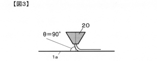
- the reinforcing fiber sheet is transported in a substantially horizontal direction, and an angle formed between the resin discharge direction and the reinforcing fiber sheet transport direction (this angle may be referred to as “coating angle” for convenience). It is important that the angle is 80 ° or less.
- FIG. 3 shows a conventional general coating method. The angle formed between the resin discharge direction and the reinforcing fiber sheet conveyance direction is 90 °.
- a thermosetting resin such as an epoxy resin
- the coating head when the coating head is pressed as described in Patent Document 1, it is considered that such a problem does not occur because no resin film is formed in the air.
- the angle formed between the resin discharge direction and the reinforcing fiber sheet conveyance direction shown in FIG. 1 is 80 ° or less, even when the resin is discharged in a planar shape to form a resin film, the resin film is stable.
- the present inventors have found that it can be applied at high speed.
- a smaller coating angle ⁇ is preferable because it can be stably applied at high speed.
- the coating angle ⁇ is preferably 30 to 70 °.
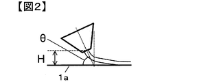
- the application height H which is the distance between the discharge line center and the reinforcing fiber sheet 1a shown in FIG. 2, is 3 mm or more, so that contamination of the application part due to resin accumulation in the application part is suppressed, and application stability is improved. Since it can improve, it is preferable. Moreover, it is preferable to set it to 18 mm or less because the formation of the resin film in the space where the resin is discharged is stabilized.
- the application unit 20 may be an apparatus capable of discharging resin in a planar shape. More specifically, as a preferred example, an apparatus capable of forming a surface or curtain-like film by discharging a resin having a uniform thickness in the width direction from a base for discharging the resin. Generally, it is a planar coating device called a curtain coating device or a die coater, and a structure in which resin can be discharged from a slit having a uniform thickness and no intermittentness can be used. Moreover, it is preferable that the application part 20 has a heating mechanism which can heat the resin 2 immediately before discharge and can adjust to arbitrary viscosity. Especially when using thermosetting resin, there is a risk of deterioration due to thermal history of the resin during storage, viscosity increase, and runaway reaction, so it is possible to shorten the resin heating time and perform appropriate temperature control. preferable.
- the resin film since the resin film has a free surface in the space where the resin is discharged, the film shape of the resin film is easily deformed.
- the resin film may not be formed because the end portion of the resin film is degenerated in the width direction due to so-called “neck-in” or the entire resin film is pulled when the reinforcing fiber sheet is conveyed at high speed.
- the resin film becomes stable and the uniformity of the basis weight of the resin film is impaired. For this reason, it is preferable to stabilize the film formation by causing an air flow to act on the end of the resin film in the width direction.
- neck-in occurs in which the end of the resin film is drawn in the center direction of the resin film in a direction perpendicular to the pulling direction (see FIGS. 5 and 6). The width is reduced by the amount indicated by G). This phenomenon is particularly likely to occur when high tension is applied to the resin film due to high viscosity of the resin or high pulling speed.
- the resin film is formed at a high speed by the prepreg manufacturing method of the present invention, it is preferable to suppress neck-in.
- the airflow for this is called end air in the present invention.
- a metal tube or a nozzle can be used as means for applying the end air.
- the air velocity, flow rate, angle, position, and temperature of the end air are preferably selected appropriately in consideration of whether the neck-in and the resin film are stably formed.
- the end air can be used when a resin film is applied.
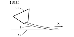
- FIG. 8 there is a case where the resin film is excessively pulled in the pulling direction of the resin film, that is, the prepreg conveying direction.
- the resin film is excessively pulled in the pulling direction of the resin film, that is, the prepreg conveying direction.
- the airflow for this purpose is referred to as surface air in the present invention. It is preferable to appropriately select the airflow velocity, flow rate, angle, position, and temperature of the surface air in consideration of whether the resin film is stably formed.
- a nozzle in which pores are generally arranged in a slit shape or on a line can be used.
- both the end air and the surface air are provided in the application unit because the device can be made compact and from the viewpoint of handleability.
- the position where a resin film contacts a reinforcement fiber sheet can also be brought close to the application part side also by attracting
- the release sheet used in the present invention is not particularly limited as long as it has sufficient release properties with respect to the resin to be applied and has appropriate elasticity and rigidity.
- a release paper or a film coated with a release agent Etc. can be used.
- the conveyance speed (line speed) of the reinforcing fiber sheet or prepreg is preferably as high as possible from the viewpoint of improving productivity.
- the conveyance speed is preferably 10 m / min to 100 m / min.
- an impregnation step can be incorporated after the resin coating step as shown in FIG. That is, the impregnation operation can be performed after applying the resin on the reinforcing fiber sheet that is continuously conveyed.
- the resin applied on the reinforcing fiber sheet penetrates into the reinforcing fiber sheet, so that the handling property as a prepreg is improved and it is caused by the unimpregnated part when processed into a composite material.
- the generation of voids can be effectively suppressed, and the deterioration of mechanical properties can be suppressed.
- the handleability may be deteriorated due to insufficient convergence of the reinforcing fibers, so that not only the mechanical properties but also the quality may be deteriorated.
- the impregnation apparatus is not particularly limited and can be appropriately selected from known ones according to the purpose.
- a laminated body of a reinforcing fiber sheet and a resin is preheated with a hot plate to sufficiently soften the resin on the reinforcing fiber sheet.
- Impregnation can be promoted by using a device that pressurizes with a heated nip roll.
- the hot plate temperature for preheating, the nip roll surface temperature, the linear pressure of the nip roll, and the diameter and number of nip rolls can be appropriately selected so as to obtain a desired degree of impregnation.
- an “S-wrap roll” in which a prepreg sheet as described in the WO 2010/150022 pamphlet travels in an S shape.
- FIG. 1 of the WO2010 / 150022 pamphlet an example in which the prepreg sheet travels in an S-shape is described.
- the contact between the sheet and the roll such as a U-shape, V-shape, or ⁇ -shape, is possible.
- the length may be adjusted.
- the impregnation pressure is increased and the impregnation degree is increased, it is possible to add an opposing contact roll. Further, as shown in FIG.
- the one in which the resin is simply laminated on the reinforcing fiber sheet and the one in which the resin is sufficiently impregnated in the reinforcing fiber are referred to as a prepreg.
- FIG. 1 only one coating unit and impregnation machine are shown, but it is of course possible to connect and install a plurality of them.
- two coating units and two impregnation machines so-called two-stage impregnation can be performed in which a resin composition containing a large amount of resin particles is applied and impregnated in the second unit.
- a highly reactive component and a stable component separately with a plurality of coating heads, even a highly reactive component can be applied in a low-reactive state (for example, at a low temperature).
- the coating conditions that can be taken in the coating process can be made flexible, which is preferable.
- the resin can be coated on both sides of the reinforcing fiber sheet.
- the application of the resin on both sides may be performed by arranging a plurality of application heads on the front and back of the same position and performing simultaneous application on both sides, or applying the resin on one side and then applying the resin on the other side. May be performed.
- FIG. 10 shows an example of a coating method on both sides.
- a plurality of reinforcing fibers 1 are drawn out from the creel 11 and the reinforcing fiber sheet 1a is formed by the arrangement device 12.
- the release sheet 3a fed out from the release sheet supply device 14a is inserted into the lower surface of the reinforcing fiber sheet 1a by the transport roll 13a.
- the resin 2a is discharged from the first coating head 20a, and the prepreg 1b to which the resin 2a is applied is formed.
- the upper and lower surfaces of the prepreg are reversed through the transport rolls 13b and 13c.
- the release sheet 3a is peeled off by the transport roll 13c, and instead, the release sheet 3b is inserted into the surface of the prepreg 1b to which the resin 2a is applied, which is opposite to the surface to which the resin 2a is applied. And the resin 2b is discharged from the 2nd application
- the resin 2a, the resin 2b, and the resin 2c may be the same type of resin, or may be different types of resins, and each may contain additives and particles.
- FIG. 11 shows another example of the application method on both sides.
- the reinforcing fiber sheet to which the resin is applied is conveyed in the horizontal direction without being folded back. Again, end air and surface air applying means are not shown.
- the application of the resin from the application head 20b can be performed using non-contact physical means such as wind force or electrostatic means.
- FIG. 12 illustrates a case where there are three coating heads, the number of coating heads may be two or four or more. Moreover, although the case where the number of impregnation machines is two is also illustrated, one or three or more may be used, and the installation location can be appropriately changed according to the purpose.
- the resin 2a is applied to the reinforcing fiber sheet 1a by the first coating head 20a, and the prepreg 1b to which the resin 2a is applied is formed. Then, the prepreg 1d provided with the resin 2b is formed by the second coating head 20b. Furthermore, the resin 2c is applied from the third application head 20c.
- the impregnation machine 17 may be after the first coating head 20a, after the second coating head 20b, or after the third coating head 20c. Further, as illustrated in FIG. 12, the first impregnation machine 17a may be disposed behind the second coating head 20b, and the second impregnation machine 17b may be disposed behind the third coating head 20c.
- the resin when a resin is applied onto a reinforcing fiber sheet conveyed in a substantially horizontal direction, the resin is discharged in a planar shape, and an angle formed between the resin discharge direction and the reinforcing fiber sheet conveying direction is 80 °.
- coating resin so that it may be the following, if the said process is included, unless the objective of this invention is impaired, the application
- the application from the second application head is an application in a state where the reinforcing fiber sheet is not substantially horizontal or the reinforcing fiber sheet is in a substantially horizontal state, but the discharge direction of the resin and the reinforcing fiber In the case where the angle formed by the sheet conveying direction exceeds 80 °, and the case where the step of applying the die in contact with the step of applying by the first application head, which is the application in the embodiment of the present invention, is combined. It is done.
- 56 yarns of carbon fibers (T800S-24K manufactured by Toray Industries, Inc.) can be used as the reinforcing fibers 1, and these are aligned in one direction using the arrangement device 12 to form a reinforcing fiber sheet 1a having a width of 300 mm.
- the release paper 3a is inserted into the lower surface of the reinforcing fiber sheet 1a by the transport roll 13a.
- the resin 2a is applied from the first application head 20a onto the reinforcing fiber sheet 1a.
- a resin A composed of a thermosetting epoxy resin (a mixture of an aromatic amine type epoxy resin and a bisphenol type epoxy resin) containing a curing agent (diaminodiphenyl sulfone) and polyether sulfone is used. It can.
- the viscosity of this resin A at 90 ° C. and 3.14 sec ⁇ 1 can be 15 Pa ⁇ s.
- a die coater having a thickness of 0.4 mm and a slit base of 300 mm in the width direction can be used.
- the resin can be melted with a melter, and then measured with a gear pump and supplied to the coating section.
- the melter, supply unit, and die coater are heated to the same temperature.
- the surface air can be supplied from a slit having a thickness of 0.1 mm right next to the application part.
- the end air can be supplied through a ⁇ 2 mm copper tube.
- the coating height H can be set to 10 mm and the coating angle can be set to 65 °.
- the end air pressure can be 0.1 MPa, and the surface air pressure can be 0.2 MPa.
- the resin 2 is collected on the table 18a, and the reinforcing fiber sheet 1a can be conveyed linearly even if there is end air or surface air.
- the prepreg 1b can be formed by discharging the resin A in a planar shape from the first coating head 20a.
- the application angle of the first application head 20a can be 65 °
- the temperature can be 90 ° C.
- the discharge amount of the resin A can be 360 g / min.
- the second coating head 20b is not used, the release paper 3b is inserted on the upper surface of the prepreg 1b to which the resin is applied by the transport roll 13b, and impregnation is performed by the first impregnation machine 17a, so that the first cooling is performed. It can be cooled by the device 19a.
- the release paper 3b is peeled off by the transport roll 13c, and the resin 2c can be applied onto the prepreg 1d using the third application head 20c.
- the resin 2c is composed of a thermosetting epoxy resin (a mixture of aromatic amine type epoxy resin + bisphenol type epoxy resin) containing a curing agent (diaminodiphenyl sulfone), polyether sulfone, and thermoplastic resin fine particles.
- Resin B can be used.
- the fine particles made of thermoplastic resin “Particle 3” described in Examples of Japanese Patent Application Laid-Open No. 2011-162619 can be used.
- the viscosity of the resin B at 105 ° C.
- the application angle of the third application head 20b can be 65 °
- the temperature can be 105 ° C.
- the discharge amount of the resin B can be 240 g / min.
- the release paper 3c is inserted into the upper surface of the prepreg 1e by the transport roll 13d, impregnated by the second impregnation machine 17b, cooled by the second cooling device 19b, and taken up by the winding device 16.
- the conveyance speed of a prepreg can be 20 m / min. In this way, a prepreg containing organic fine particles can be produced.
- a resin C made of a mixture of an aromatic amine type epoxy resin and a polyethersulfone is used as the resin 2a applied by the first application head 20a, and the discharge rate is 280 g / min.
- the temperature of the coating head 20a can be 120 ° C. and the coating angle can be 65 °.
- the viscosity of the resin C at 120 ° C. and 3.14 sec ⁇ 1 can be 7 Pa ⁇ s. At this time, since the resin C has a low viscosity, the coating height can be reduced to 5 mm.
- a resin D made of a bisphenol type epoxy resin containing a curing agent (diaminodiphenylsulfone) is used, the discharge amount is 320 g / min, the application head 20b temperature is 30 ° C., The application angle can be 65 °.
- the viscosity of the resin D at 30 ° C. and 3.14 sec ⁇ 1 can be 15 Pa ⁇ s.
- Polyethersulfone has a long molecular chain and becomes highly viscous due to entanglement, so a high temperature is necessary for coating.
- the curing agent is preferably handled as low a temperature as possible to suppress the curing reaction. .
- the temperature can be set to a preferable temperature for each coating head.
- Each resin is applied to the carbon fiber sheet, a prepreg 1d to which the resin is applied is formed, the release paper 3b is inserted into the upper surface, and then impregnated by the first impregnation machine 17a and cooled by the first cooling device 19a. It can be carried out. Thereafter, the release paper 3 b can be peeled off and wound up by the winding device 16.
- the sticking property tackiness
- thermoplastic resin such as polyethersulfone has a higher storage elastic modulus than that of the epoxy resin.
- the prepreg obtained in the above aspect B can reduce the amount of polyethersulfone present on the surface of the prepreg, so that the tackiness can be increased.
- a bisphenol-type epoxy resin containing thermoplastic resin fine particles (the “particle 3”) is used as the resin 2c in the third coating head, and further thermoplastic resin fine particles are applied to the prepreg surface.
- the resin 2c in the third coating head is used as the resin 2c in the third coating head, and further thermoplastic resin fine particles are applied to the prepreg surface.
- urethane particles or polyamide particles can be used in place of “Particle 3” (Aspect D).
- a mixture of bisphenol-type epoxy resin and carbon particles can be added instead of the thermoplastic resin fine particles (Aspect E).
- inorganic particles such as metal particles, metal oxides, and nitrides can be used instead of carbon particles (Aspect F).
- a mixture of a flame retardant such as red phosphorus and an epoxy resin can be used instead of the fine particles (Aspect G).
- the solid material can be selected according to the purpose, such as a curing agent, organic fine particles for improving toughness and vibration damping properties, inorganic fine particles for improving conductivity, and a flame retardant.
- the prepreg obtained by the production method of the present invention can be converted to CFRP by ordinary CFRP conversion technology / equipment, and after obtaining the prepreg by the above prepreg manufacturing method, it is cured to manufacture a fiber-reinforced composite material. Therefore, it is highly versatile and adaptable to facilities. For this reason, it can use suitably for the goods which consist of various CFRP and / or include in part.
- a UD sheet having a width of 280 mm was formed using 56 yarns of carbon fiber “Torayca (registered trademark)” T800S-24K (manufactured by Toray Industries, Inc.) and the alignment device 12 in FIG.
- resin E having the following composition was used as a matrix resin for the prepreg.
- the resin E is made of an epoxy resin (a mixture of an aromatic amine type epoxy resin and a bisphenol type epoxy resin) containing a curing agent (diaminodiphenyl sulfone) and polyether sulfone.
- the viscosity of the matrix resin was measured using a dynamic viscoelasticity measuring device (ARES: manufactured by TA Instruments). With this apparatus, a parallel plate having a diameter of 40 mm is used, the gap between the plates is set to 1 mm, and the matrix resin is set therebetween. Then, measurement was performed at a measurement frequency of 0.5 Hz (3.14 sec ⁇ 1 ) and a temperature increase rate of 1.5 ° C./min to obtain a temperature-viscosity curve. The viscosity of the resin E was 35 Pa ⁇ s at 70 ° C. The viscosities of the matrix resins shown in the present examples and comparative examples are obtained by reading the viscosities at the set temperature of the coated part in the temperature-viscosity curves obtained here.
- ADS dynamic viscoelasticity measuring device
- a coating device As a coating device, a die coater having a thickness of 0.4 mm and a slit base of 300 mm in the width direction was used. The resin was melted with a melter, then weighed with a gear pump, and supplied to the coating part. The melter, the supply unit, and the die coater were heated to the same temperature. The surface air 21 was supplied from a slit having a thickness of 0.1 mm directly to the application part. The end air 22 was supplied via a ⁇ 2 mm copper tube (see FIG. 9).
- the obtained prepreg was pulled out in the longitudinal direction at least 1 m and a total area of at least 1 m 2 in the area of the prepreg, an approximately minimum amount of samples satisfying both conditions were collected, and the surface was visually observed.
- the evaluation was made as “ ⁇ ”, and when some arrangement disturbance was observed, it was evaluated as “X”.
- the surface was visually observed by drawing 4 m or more in the longitudinal direction, performing sampling, and sampling.
- the prepreg production stability was evaluated based on the continuous running time at a conveyance speed (running speed) of 10 m / min. ⁇ : 60 minutes or more ⁇ : 10 minutes or more and less than 60 minutes ⁇ : less than 10 minutes.
- Examples 1 to 3 The steps used in this example are shown in FIG. 1 (the impregnation machine 17 was not used), and the coating apparatus is shown in FIG.
- the discharge amount of the resin E was 97 g / min
- the application part temperature was 70 ° C.
- the end air pressure was 0.1 MPa
- the face part air pressure was 0.2 MPa.
- the resin E was applied to the carbon fiber sheet at a traveling speed of 20 m / min under the conditions shown in Table 1, but no fluff clogging or yarn breakage occurred, no signs of fluff clogging were observed, and an excellent prepreg The production speed.
- the carbon fiber sheet was coated with resin E, and no coating defects were observed.
- Example 1 having a large coating angle ⁇ the stability was slightly unstable, although not so much as to cause a problem.
- Example 4 Coating was performed in the same manner as in Example 1 except that the coating angle and coating height were changed as shown in Table 1.
- the application angle was as small as 25 °, the application part could interfere with the process, so the application height was 20 mm. For this reason, the formation of the resin film in the air is slightly unstable, and the stability is slightly lowered although not problematic.
- Example 1 Coating was performed in the same manner as in Example 1 except that the coating angle was 90 °. However, at a traveling speed of 20 m / min, stable coating could not be performed due to the tearing of the resin film. For this reason, in order to reduce the viscosity of the resin E, the temperature of the coating part was raised to 105 ° C., and further, the running speed was lowered and a coating experiment was performed. However, the production speed and stability were poor, and stable coating was not possible. could not.
- Example 5 Coating was performed in the same manner as in Example 2 except that the traveling speed was set to 10 m / min, but neck-in was suppressed.
- Example 6 Application was performed in the same manner as in Example 5 except that the end air was not used, but there was a tendency for neck-in to increase.
- Example 7 to 12 A prepreg was produced under the same conditions as in Examples 1 to 6 except that impregnation was performed using an impregnation machine 17 (Example 1 corresponds to Example 7, Example 2 corresponds to Example 8. The same applies hereinafter. ). Furthermore, this was laminated and bagged so as to be pseudo-isotropic, and then cured in an autoclave at a temperature of 180 ° C. and a pressure of 6 atm for 2 hours to obtain a carbon fiber reinforced composite material. Good quality and mechanical properties were obtained.
- Resin F shown below as matrix resin, discharge rate of resin F of 600 g / min, application part temperature of 85 ° C., and prepreg under the conditions described in Table 3 as in Examples 1 to 4.
- Resin F is composed of an epoxy resin (a mixture of an aromatic amine type epoxy resin and a bisphenol type epoxy resin) containing a curing agent (diaminodiphenyl sulfone) and polyether sulfone, and a viscosity at 85 ° C. and 3.14 sec ⁇ 1 is 21 Pa. ⁇ It was s.
- any of the examples at a traveling speed of 10 m / min or more, there was no breakage of the resin film in the coating process, and there was no occurrence of fuzz due to disordered fiber arrangement or coating, and an excellent quality prepreg was obtained. .
- the traveling speed was as high as 20 m / min or higher.
- the production stability was also excellent. Further, in Examples 13 to 15, neck-in could be sufficiently suppressed.
- Example 2 Coating was performed in the same manner as in Example 14 except that the coating angle was 90 °. However, at a traveling speed of 20 m / min, stable coating could not be performed due to the tearing of the resin film. For this reason, in order to reduce the viscosity of the resin E, the temperature of the coating part was raised to 105 ° C., and further, the running speed was lowered and a coating experiment was performed. However, the production speed and stability were poor, and stable coating was not possible. could not.
- Example 17 When the coating was performed in the same manner as in Example 14 except that the end air pressure was set to 0.02 MPa, the neck-in tended to be large although not problematic.
- Example 18 Application was performed in the same manner as in Example 14 except that the traveling speed was set to 10 m / min and the surface air pressure was set to 0.02 MPa. However, although not problematic, the traveling stability did not reach Example 14. .
- Example 19 to 24 In Examples 19 and 24, the discharge rate of resin F was 300 g / min and the production rate was 10 m / min, and in Examples 20 to 23, the discharge rate of resin F was 600 g / min and the production rate was 20 m / min.
- a prepreg was produced under the same conditions as in Examples 13 to 18 except that impregnation was performed using an impregnation machine 17 in all Examples (Example 13 corresponds to Example 19 and Example 14 corresponds to Example 20). Corresponding, and so on) Furthermore, this was laminated and bagged so as to be pseudo-isotropic, and then cured in an autoclave at a temperature of 180 ° C. and a pressure of 6 atm for 2 hours to obtain a carbon fiber reinforced composite material. Good quality and mechanical properties were obtained.
Abstract
Description
第1の態様として、態様Aを下記に説明する。まず、第1の塗布ヘッド20aから樹脂Aを面状に吐出しプリプレグ1bを形成することができる。ここで第1の塗布ヘッド20aの塗布角を65°、温度は90℃、樹脂Aの吐出量は360g/分とすることができる。その後、第2の塗布ヘッド20bは使用せず、搬送ロール13bにて樹脂が付与されたプリプレグ1b上面に離型紙3bが挿入され、第1の含浸機17aで含浸が行われ、第1の冷却装置19aで冷却されることができる。そして、搬送ロール13cで離型紙3bが剥がされ、第3の塗布ヘッド20cを用い、樹脂2cをプリプレグ1d上に塗布することができる。この時、樹脂2cとしては、硬化剤(ジアミノジフェニルスルホン)とポリエーテルスルホン、熱可塑樹脂製微粒子を含有した熱硬化性エポキシ樹脂(芳香族アミン型エポキシ樹脂+ビスフェノール型エポキシ樹脂の混合物)から成る樹脂Bを用いることができる。ここで、熱可塑樹脂製微粒子としては、特開2011-162619号公報実施例記載の「粒子3」を用いることができる。樹脂Bの105℃、3.14sec-1における粘度は15Pa・sとすることができる。第3の塗布ヘッド20bの塗布角を65°、温度は105℃、樹脂Bの吐出量は240g/分とすることができる。その後、搬送ロール13dにてプリプレグ1e上面に離型紙3cが挿入され、第2の含浸機17bで含浸が行われ、第2の冷却装置19bで冷却され、巻き取り装置16で巻き取ることができる。なお、プリプレグの搬送速度は20m/分とすることができる。このようにして、有機微粒子を含有するプリプレグを製造することができる。 <Aspect A>
As a first aspect, aspect A will be described below. First, the
態様Aとは別の態様である態様Bでは、第1の塗布ヘッド20aで塗布する樹脂2aとして芳香族アミン型エポキシ樹脂とポリエーテルスルホンの混合物から成る樹脂Cを用い、吐出量を280g/分、塗布ヘッド20a温度を120℃、塗布角を65°とすることができる。樹脂Cの120℃、3.14sec-1における粘度は7Pa・sとすることができる。この時は、樹脂Cが低粘度となるため塗布高さを低くし、5mmとすることができる。また、第2の塗布ヘッド20bで塗布する樹脂2bとして硬化剤(ジアミノジフェニルスルホン)を含有したビスフェノール型エポキシ樹脂から成る樹脂Dを用い、吐出量を320g/分、塗布ヘッド20b温度を30℃、塗布角を65°とすることができる。樹脂Dの30℃、3.14sec-1における粘度は15Pa・sとすることができる。ポリエーテルスルホンは分子鎖が長く絡み合いに起因して高粘度となるため、塗布のためには高温が必要であるが、一方で硬化剤は硬化反応を抑制するためになるべく低温で扱うことが好ましい。このため、本態様Bのようにポリエーテルスルホンのような高粘度起因物と硬化剤を分けると、それぞれの塗布ヘッドで好ましい温度に設定することができる。炭素繊維シートにそれぞれの樹脂を塗布し、樹脂が付与されたプリプレグ1dを形成し、離型紙3bを上面に挿入した後、第1の含浸機17aで含浸、第1の冷却装置19aで冷却を行うことができる。その後、離型紙3bを剥がし巻き取り装置16で巻き取ることができる。一般に、プリプレグ表面に貯蔵弾性率の高い樹脂が多いと貼りつき性(タック性)が低下するが。CFRP用のマトリックス樹脂では、ポリエーテルスルホンなどの熱可塑性樹脂の貯蔵弾性率がエポキシ樹脂に比べ高いため、これがプリプレグ表面に多いとタック性が低下する。上記様態Bで得られるプリプレグは、プリプレグ表面に存在するポリエーテルスルホン量を少なくできるため、タック性を高くすることができる。 <Aspect B>
In the aspect B which is an aspect different from the aspect A, a resin C made of a mixture of an aromatic amine type epoxy resin and a polyethersulfone is used as the
炭素繊維“トレカ(登録商標)”T800S-24K(東レ(株)製))56糸条用い、図1中の配列装置12を用い、幅280mmのUDシートを形成した。 (Reinforced fiber sheet)
A UD sheet having a width of 280 mm was formed using 56 yarns of carbon fiber “Torayca (registered trademark)” T800S-24K (manufactured by Toray Industries, Inc.) and the
各実施例、比較例ではプリプレグのマトリックス樹脂として、以下の配合の樹脂Eを用いた。樹脂Eは、硬化剤(ジアミノジフェニルスルホン)、ポリエーテルスルホンを含有するエポキシ樹脂(芳香族アミン型エポキシ樹脂+ビスフェノール型エポキシ樹脂の混合物)から成る。 (Matrix resin)
In each example and comparative example, resin E having the following composition was used as a matrix resin for the prepreg. The resin E is made of an epoxy resin (a mixture of an aromatic amine type epoxy resin and a bisphenol type epoxy resin) containing a curing agent (diaminodiphenyl sulfone) and polyether sulfone.
前記マトリックス樹脂の粘度は動的粘弾性測定装置(ARES:TAインスツルメント社製)を用いて測定した。該装置で、直径40mmのパラレルプレートを用い、プレート間ギャップを1mmとして、マトリックス樹脂をその間にセットする。そして、測定周波数0.5Hz(3.14sec-1)、昇温速度1.5℃/分で測定を行い、温度-粘度カーブを得た。前記樹脂Eの粘度は70℃で35Pa・sであった。本実施例・比較例に示すマトリックス樹脂の粘度は、ここで得た温度-粘度カーブにおいて、塗布部の設定温度での粘度を読み取ったものである。 (Viscosity measurement)
The viscosity of the matrix resin was measured using a dynamic viscoelasticity measuring device (ARES: manufactured by TA Instruments). With this apparatus, a parallel plate having a diameter of 40 mm is used, the gap between the plates is set to 1 mm, and the matrix resin is set therebetween. Then, measurement was performed at a measurement frequency of 0.5 Hz (3.14 sec −1 ) and a temperature increase rate of 1.5 ° C./min to obtain a temperature-viscosity curve. The viscosity of the resin E was 35 Pa · s at 70 ° C. The viscosities of the matrix resins shown in the present examples and comparative examples are obtained by reading the viscosities at the set temperature of the coated part in the temperature-viscosity curves obtained here.
塗布装置として、0.4mmの厚みで幅方向に300mmのスリット口金を持つダイコーターを使用した。樹脂はメルターで溶融し、その後、ギヤポンプで計量し、塗布部に供給した。なお、メルター~供給部~ダイコーターは同じ温度になるよう加温した。面部エア21は、塗布部直横に厚み0.1mmのスリットから供給した。また端部エア22はφ2mmの銅管を介して供給した(図9参照)。 (Resin coating device)
As a coating device, a die coater having a thickness of 0.4 mm and a slit base of 300 mm in the width direction was used. The resin was melted with a melter, then weighed with a gear pump, and supplied to the coating part. The melter, the supply unit, and the die coater were heated to the same temperature. The
得られたプリプレグを長手方向に少なくとも1m以上、かつプリプレグの面積で合計少なくとも1m2以上を引き出し、両条件を満たす概略最少量の試料を採取し、目視で表面観察を行った。繊維配列の乱れがない場合には○、一部に配列乱れが観察された場合は×として評価を行った。例えば280mm幅のプリプレグであれば、長手方向に4m以上引き出し、サンプリングを行って、目視で表面観察を行った。 (Observation of disorder of reinforcing fiber array on prepreg surface)
The obtained prepreg was pulled out in the longitudinal direction at least 1 m and a total area of at least 1 m 2 in the area of the prepreg, an approximately minimum amount of samples satisfying both conditions were collected, and the surface was visually observed. When there was no disturbance in the fiber arrangement, the evaluation was made as “◯”, and when some arrangement disturbance was observed, it was evaluated as “X”. For example, in the case of a prepreg having a width of 280 mm, the surface was visually observed by drawing 4 m or more in the longitudinal direction, performing sampling, and sampling.
樹脂膜破れなく製造し得る最高製造速度(走行速度)を評価し、△以上を合格とした。
◎:20m/分以上
○:10m/分以上20m/分未満
△:5m/分以上10m/分未満
×:5m/分未満。 (Evaluation of production speed)
The maximum production speed (running speed) that can be produced without breaking the resin film was evaluated, and Δ or higher was regarded as acceptable.
A: 20 m / min or more B: 10 m / min or more and less than 20 m / min Δ: 5 m / min or more and less than 10 m / min X: less than 5 m / min.
プリプレグ製造安定性を搬送速度(走行速度)10m/分での連続走行可能時間で評価し、△以上を合格とした。
○:60分以上
△:10分以上60分未満
×:10分未満。 (Evaluation of stability)
The prepreg production stability was evaluated based on the continuous running time at a conveyance speed (running speed) of 10 m / min.
○: 60 minutes or more Δ: 10 minutes or more and less than 60 minutes ×: less than 10 minutes.
強化繊維シート上に樹脂を塗布した際の各々のネックインの量(G部分の長さ。図5、図6参照)を評価し、△以上を合格とした。
○:10mm未満
△:10mm以上20mm未満
×:20mm以上。 (Neck-in evaluation)
The amount of each neck-in (the length of the G portion, see FIGS. 5 and 6) when the resin was applied onto the reinforcing fiber sheet was evaluated, and Δ or more was regarded as acceptable.
○: Less than 10 mm Δ: 10 mm or more and less than 20 mm x: 20 mm or more.
本実施例で用いた工程を図1(含浸機17は使用しなかった)、塗布装置を図9に示した。また、樹脂Eの吐出量は97g/分、塗布部温度は70℃、端部エア圧力は0.1MPa、面部エア圧は0.2MPaで作用させた。これにより、表1に記載の条件で炭素繊維シートに樹脂Eを走行速度20m/分で塗布したが、毛羽詰まりや糸切れは発生せず、また毛羽詰まりの兆候も見られず、優れたプリプレグ製造速度であった。さらに炭素繊維シート上は樹脂Eで塗れており、塗布欠点は見られなかった。ただし、塗布角θの大きい実施例1では、問題となるほどではないが、若干安定性が不安定であった。 [Examples 1 to 3]
The steps used in this example are shown in FIG. 1 (the
塗布角、塗布高さを表1のように変更した以外は実施例1と同様にして塗布を行った。実施例4では塗布角が25°と小さいために塗布部が工程に干渉するおそれがあったので、塗布高さを20mmとした。このため、空中での樹脂膜の形成が若干不安定となり、問題となるほどではないが安定性が若干低下した。 [Example 4]
Coating was performed in the same manner as in Example 1 except that the coating angle and coating height were changed as shown in Table 1. In Example 4, since the application angle was as small as 25 °, the application part could interfere with the process, so the application height was 20 mm. For this reason, the formation of the resin film in the air is slightly unstable, and the stability is slightly lowered although not problematic.
塗布角を90°とした以外は実施例1と同様に塗布を行ったが、走行速度20m/分では樹脂膜の破れにより安定な塗布はできなかった。このため、樹脂Eの粘度を低下させるため、塗布部の温度を105℃まで上げ、さらに走行速度を低下させて塗布実験を行ったが、製造速度、安定性とも不良であり、安定な塗布はできなかった。 [Comparative Example 1]
Coating was performed in the same manner as in Example 1 except that the coating angle was 90 °. However, at a traveling speed of 20 m / min, stable coating could not be performed due to the tearing of the resin film. For this reason, in order to reduce the viscosity of the resin E, the temperature of the coating part was raised to 105 ° C., and further, the running speed was lowered and a coating experiment was performed. However, the production speed and stability were poor, and stable coating was not possible. could not.
走行速度を10m/分とした以外は実施例2と同様にして塗布を行ったが、ネックインは抑制されていた。 [Example 5]
Coating was performed in the same manner as in Example 2 except that the traveling speed was set to 10 m / min, but neck-in was suppressed.
端部エアを用いない以外は実施例5と同様にして塗布を行ったが、ネックインが大きくなる傾向が見られた。 [Example 6]
Application was performed in the same manner as in Example 5 except that the end air was not used, but there was a tendency for neck-in to increase.


含浸機17を用いて含浸を行った以外は実施例1~6と同じ条件でプリプレグを作製した(実施例1が実施例7に対応し、実施例2が実施例8に対応する。以下同様)。さらに、これを擬似等方となるように積層、バギングした後、オートクレーブ中で、温度180℃、圧力6気圧で2時間硬化させて炭素繊維強化複合材料を得た。品位、力学特性とも良好なものが得られた。 [Examples 7 to 12]
A prepreg was produced under the same conditions as in Examples 1 to 6 except that impregnation was performed using an impregnation machine 17 (Example 1 corresponds to Example 7, Example 2 corresponds to Example 8. The same applies hereinafter. ). Furthermore, this was laminated and bagged so as to be pseudo-isotropic, and then cured in an autoclave at a temperature of 180 ° C. and a pressure of 6 atm for 2 hours to obtain a carbon fiber reinforced composite material. Good quality and mechanical properties were obtained.
炭素繊維を53糸条、マトリックス樹脂として下記に示す樹脂Fを用い、樹脂Fの吐出量を600g/分、塗布部温度を85℃として実施例1~4と同様に表3記載の条件でプリプレグを作製した。樹脂Fは、硬化剤(ジアミノジフェニルスルホン)とポリエーテルスルホンを含むエポキシ樹脂(芳香族アミン型エポキシ樹脂+ビスフェノール型エポキシ樹脂の混合物)から成り、85℃、3.14sec-1での粘度は21Pa・sであった。 [Examples 13 to 16]
Using carbon fiber as 53 yarns, resin F shown below as matrix resin, discharge rate of resin F of 600 g / min, application part temperature of 85 ° C., and prepreg under the conditions described in Table 3 as in Examples 1 to 4. Was made. Resin F is composed of an epoxy resin (a mixture of an aromatic amine type epoxy resin and a bisphenol type epoxy resin) containing a curing agent (diaminodiphenyl sulfone) and polyether sulfone, and a viscosity at 85 ° C. and 3.14 sec −1 is 21 Pa.・ It was s.
塗布角を90°とした以外は実施例14と同様に塗布を行ったが、走行速度20m/分では樹脂膜の破れにより安定な塗布はできなかった。このため、樹脂Eの粘度を低下させるため、塗布部の温度を105℃まで上げ、さらに走行速度を低下させて塗布実験を行ったが、製造速度、安定性とも不良であり、安定な塗布はできなかった。 [Comparative Example 2]
Coating was performed in the same manner as in Example 14 except that the coating angle was 90 °. However, at a traveling speed of 20 m / min, stable coating could not be performed due to the tearing of the resin film. For this reason, in order to reduce the viscosity of the resin E, the temperature of the coating part was raised to 105 ° C., and further, the running speed was lowered and a coating experiment was performed. However, the production speed and stability were poor, and stable coating was not possible. could not.

端部エア圧力を0.02MPaとした以外は実施例14と同様にして塗布を行ったところ、問題となるほどではないがネックインが大きくなる傾向が見られた。 [Example 17]
When the coating was performed in the same manner as in Example 14 except that the end air pressure was set to 0.02 MPa, the neck-in tended to be large although not problematic.
走行速度を10m/分とし、面部エア圧力を0.02MPaとした以外は実施例14と同様にして塗布を行ったところ、問題となるほどではないが走行安定性が実施例14には及ばなかった。 [Example 18]
Application was performed in the same manner as in Example 14 except that the traveling speed was set to 10 m / min and the surface air pressure was set to 0.02 MPa. However, although not problematic, the traveling stability did not reach Example 14. .
実施例19、24は樹脂Fの吐出量を300g/分で製造速度を10m/分、実施例20~23は樹脂Fの吐出量を600g/分で製造速度を20m/分とし、また、これら全ての実施例で含浸機17を用いて含浸を行った以外は実施例13~18と同じ条件でプリプレグを作製した(実施例13が実施例19に対応し、実施例14が実施例20に対応する。以下同様)。さらに、これを擬似等方となるように積層、バギングした後、オートクレーブ中で、温度180℃、圧力6気圧で2時間硬化させて炭素繊維強化複合材料を得た。品位、力学特性とも良好なものが得られた。 [Examples 19 to 24]
In Examples 19 and 24, the discharge rate of resin F was 300 g / min and the production rate was 10 m / min, and in Examples 20 to 23, the discharge rate of resin F was 600 g / min and the production rate was 20 m / min. A prepreg was produced under the same conditions as in Examples 13 to 18 except that impregnation was performed using an
本出願は、2017年03月22日出願の日本国特許出願、特願2017-055613に基づくものであり、その内容はここに参照として取り込まれる。
This application is based on Japanese Patent Application No. 2017-055613 filed on Mar. 22, 2017, the contents of which are incorporated herein by reference.
1a 強化繊維シート
1b、1c、1d、1e 樹脂が付与された強化繊維シート(プリプレグ)
2、2a、2b、2c、2d 樹脂
3、3a、3b、3c 離型シート
11 クリール
12 配列装置
13a、13b、13c、13d、13e 搬送ロール
14a、14b、14c 離型シート供給装置
15、15a、15b 離型シート巻取装置
16 巻取り装置
17 含浸装置
18a、18b、18c テーブル
19、19a、19b 冷却装置
20 塗布部
20a 第1の塗布ヘッド
20b 第2の塗布ヘッド
20c 第3の塗布ヘッド
21 面部エア
22 端部エア
E 端部エアの吹き付け方向
F 面部エアの吹き付け方向
G ネックイン
H 塗布高さ
X 強化繊維シート1aの走行方向(水平方向)
B 強化繊維シート1aの走行方向(水平方向)に対し鉛直方向
θ 塗布角
DESCRIPTION OF
2, 2a, 2b, 2c,
B Vertical direction θ with respect to the traveling direction (horizontal direction) of the reinforcing
Claims (6)
- 溶融された樹脂を面状に吐出し、形成された樹脂膜を連続的に搬送される強化繊維シート上に塗布するプリプレグの製造方法において、強化繊維シートが実質的に水平方向に搬送され、樹脂の吐出方向と強化繊維シート搬送方向の成す角度が80°以下であるプリプレグの製造方法。 In a method for producing a prepreg, in which molten resin is discharged in a planar shape and the formed resin film is applied onto a reinforcing fiber sheet that is continuously transported, the reinforcing fiber sheet is transported substantially horizontally and the resin The manufacturing method of the prepreg whose angle which the discharge direction of this and the reinforcing fiber sheet conveyance direction make is 80 degrees or less.
- 樹脂膜を強化繊維シート上に塗布する際に、樹脂膜の幅方向の端部に気流を作用させる請求項1記載のプリプレグの製造方法。 The method for producing a prepreg according to claim 1, wherein when applying the resin film on the reinforcing fiber sheet, an air flow is applied to an end portion in the width direction of the resin film.
- 塗布ヘッドを2台以上用い、強化繊維シートの両面に樹脂、樹脂と添加剤の混合物および添加剤からなる群から選ばれる物質を塗布する請求項1または2に記載のプリプレグの製造方法。 The method for producing a prepreg according to claim 1 or 2, wherein two or more coating heads are used, and a material selected from the group consisting of a resin, a mixture of a resin and an additive, and an additive is applied to both surfaces of the reinforcing fiber sheet.
- 塗布ヘッドを2台以上用い、2種類以上の樹脂を塗布する請求項1~3のいずれか1項記載のプリプレグの製造方法。 The method for producing a prepreg according to any one of claims 1 to 3, wherein two or more kinds of resins are applied using two or more coating heads.
- 樹脂膜を強化繊維シート上に塗布した後、含浸を行う、請求項1~4のいずれか1項記載のプリプレグの製造方法。 The method for producing a prepreg according to any one of claims 1 to 4, wherein the resin film is applied onto the reinforcing fiber sheet and then impregnated.
- 請求項1~5のいずれか1項記載のプリプレグの製造方法でプリプレグを得た後、該プリプレグを硬化させる工程を有する繊維強化複合材料の製造方法。
A method for producing a fiber-reinforced composite material, comprising: obtaining a prepreg by the method for producing a prepreg according to any one of claims 1 to 5, and then curing the prepreg.
Priority Applications (7)
| Application Number | Priority Date | Filing Date | Title |
|---|---|---|---|
| KR1020197027222A KR102351894B1 (en) | 2017-03-22 | 2018-02-22 | Method for manufacturing prepreg and method for manufacturing fiber-reinforced composite material |
| RU2019133119A RU2019133119A (en) | 2017-03-22 | 2018-02-22 | METHOD FOR PRODUCING PREPREH AND METHOD FOR PRODUCING FIBER-REINFORCED COMPOSITE MATERIAL |
| EP18772497.6A EP3603916B1 (en) | 2017-03-22 | 2018-02-22 | Method for producing prepreg and method for producing fiber-reinforced composite material |
| JP2018511188A JP6947169B2 (en) | 2017-03-22 | 2018-02-22 | Manufacturing method of prepreg and manufacturing method of fiber reinforced composite material |
| CN201880018801.7A CN110461557B (en) | 2017-03-22 | 2018-02-22 | Method for producing prepreg and method for producing fiber-reinforced composite material |
| ES18772497T ES2943478T3 (en) | 2017-03-22 | 2018-02-22 | Method for producing prepreg and method for producing fiber-reinforced composite material |
| US16/494,824 US11806899B2 (en) | 2017-03-22 | 2018-02-22 | Method for producing prepreg and method for producing fiber-reinforced composite material |
Applications Claiming Priority (2)
| Application Number | Priority Date | Filing Date | Title |
|---|---|---|---|
| JP2017-055613 | 2017-03-22 | ||
| JP2017055613 | 2017-03-22 |
Publications (1)
| Publication Number | Publication Date |
|---|---|
| WO2018173618A1 true WO2018173618A1 (en) | 2018-09-27 |
Family
ID=63585428
Family Applications (1)
| Application Number | Title | Priority Date | Filing Date |
|---|---|---|---|
| PCT/JP2018/006483 WO2018173618A1 (en) | 2017-03-22 | 2018-02-22 | Method for producing prepreg and method for producing fiber-reinforced composite material |
Country Status (8)
| Country | Link |
|---|---|
| US (1) | US11806899B2 (en) |
| EP (1) | EP3603916B1 (en) |
| JP (1) | JP6947169B2 (en) |
| KR (1) | KR102351894B1 (en) |
| CN (1) | CN110461557B (en) |
| ES (1) | ES2943478T3 (en) |
| RU (1) | RU2019133119A (en) |
| WO (1) | WO2018173618A1 (en) |
Cited By (3)
| Publication number | Priority date | Publication date | Assignee | Title |
|---|---|---|---|---|
| KR20200037961A (en) * | 2018-10-02 | 2020-04-10 | 주식회사 무창에프엔지 | Attaching apparatus for film on glass using air |
| WO2023074733A1 (en) | 2021-10-27 | 2023-05-04 | 東レ株式会社 | Carbon fiber-reinforced composite material |
| WO2024053388A1 (en) * | 2022-09-08 | 2024-03-14 | 東レ株式会社 | Slurry impregnated sheet manufacturing device |
Families Citing this family (4)
| Publication number | Priority date | Publication date | Assignee | Title |
|---|---|---|---|---|
| KR102312952B1 (en) * | 2017-03-22 | 2021-10-13 | 도레이 카부시키가이샤 | Method for manufacturing prepreg and method for manufacturing fiber-reinforced composite material |
| BE1028055B1 (en) * | 2020-02-13 | 2021-09-13 | Basaltex Nv | PROCEDURE FOR PRODUCING A FIRE AND HEAT RESISTANT PRE-IMPREGNATED FIBER MATERIAL |
| KR102265029B1 (en) * | 2020-09-21 | 2021-06-14 | 김국진 | Apparatus for manufacturing composite laminated prepreg |
| CN113172906B (en) * | 2021-04-26 | 2023-07-04 | 江苏奇一科技有限公司 | Preparation method and equipment of pressure-sensitive continuous fiber reinforced resin prepreg tape |
Citations (21)
| Publication number | Priority date | Publication date | Assignee | Title |
|---|---|---|---|---|
| JPH01104624A (en) | 1987-10-16 | 1989-04-21 | Toray Ind Inc | Prepreg using resin fine particles |
| JPH07109670A (en) * | 1993-10-08 | 1995-04-25 | Toray Ind Inc | Process for preventing pilling of cloth and antipilling cloth |
| JPH09225938A (en) * | 1996-02-23 | 1997-09-02 | Sumitomo Bakelite Co Ltd | Method and device for manufacturing prepreg |
| WO2003091015A1 (en) | 2002-04-23 | 2003-11-06 | Toray Industries, Inc. | Prepreg, process for producing the same, and molded article |
| JP2004290771A (en) * | 2003-03-26 | 2004-10-21 | Sumitomo Bakelite Co Ltd | Method for producing composite material |
| WO2009142231A1 (en) | 2008-05-21 | 2009-11-26 | 東レ株式会社 | Method for producing polymer fine particle |
| WO2010137558A1 (en) * | 2009-05-26 | 2010-12-02 | パナソニック電工株式会社 | Method for manufacturing prepreg for printed wiring board and device for manufacturing prepreg for printed wiring board |
| WO2010150022A1 (en) | 2009-06-26 | 2010-12-29 | Hexcel Composites Limited | Process for manufacturing composite materials |
| JP2011132389A (en) | 2009-12-25 | 2011-07-07 | Toray Ind Inc | Sheet-like prepreg and manufacturing method thereof |
| JP2011162619A (en) | 2010-02-08 | 2011-08-25 | Toray Ind Inc | Epoxy resin composition, prepreg and fiber reinforced composite material |
| JP2011251524A (en) * | 2010-05-06 | 2011-12-15 | Toyobo Co Ltd | Coating die for solution film-forming and solution film-forming method |
| JP2013022868A (en) | 2011-07-22 | 2013-02-04 | Sumitomo Bakelite Co Ltd | Method for manufacturing laminate sheet web, laminate sheet web, prepreg, laminated plate, and printed wiring board |
| JP2013184356A (en) | 2012-03-07 | 2013-09-19 | Japan Steel Works Ltd:The | Fiber-reinforced resin base material, and method of manufacturing resin molding and resin processing machine for carrying out the same |
| JP2014000496A (en) * | 2012-06-15 | 2014-01-09 | Mitsubishi Rayon Co Ltd | Method for forming coating film |
| JP2014069391A (en) | 2012-09-28 | 2014-04-21 | Mitsubishi Rayon Co Ltd | Method of producing prepreg |
| WO2015060299A1 (en) | 2013-10-22 | 2015-04-30 | 三菱レイヨン株式会社 | Prepreg production method |
| WO2015076981A1 (en) | 2013-11-22 | 2015-05-28 | Cytec Industries Inc. | Method and system for impregnating fibers to form a prepreg |
| JP2016203397A (en) | 2015-04-15 | 2016-12-08 | 東邦テナックス株式会社 | Method for producing prepreg |
| JP2017055613A (en) | 2015-09-11 | 2017-03-16 | 住友電装株式会社 | Shielded conductive path |
| WO2017068159A1 (en) | 2015-10-21 | 2017-04-27 | Hexcel Composites Limited | Impregnation process using ultrasound energy |
| JP2017154330A (en) | 2016-03-01 | 2017-09-07 | 三菱ケミカル株式会社 | Apparatus for impregnating reinforced fiber with resin and method for impregnating reinforced fiber with resin |
Family Cites Families (14)
| Publication number | Priority date | Publication date | Assignee | Title |
|---|---|---|---|---|
| JP3358849B2 (en) * | 1993-08-17 | 2002-12-24 | 住友化学工業株式会社 | Coated die for manufacturing long fiber reinforced thermoplastic resin composition |
| JP3336911B2 (en) * | 1996-06-20 | 2002-10-21 | 松下電工株式会社 | Prepreg manufacturing method and apparatus |
| FR2807966B1 (en) * | 2000-04-25 | 2003-01-17 | Vetrotex France Sa | PROCESS AND DEVICE FOR MANUFACTURING A COMPOSITE PROFILE FORMED FROM ORGANIC THERMOPLASTIC MATERIAL REINFORCED BY REINFORCING FIBERS |
| US6632850B2 (en) * | 2001-04-04 | 2003-10-14 | 3M Innovative Properties Company | Microporous materials and methods of making the same |
| JP2007320038A (en) * | 2006-05-30 | 2007-12-13 | Sumitomo Chemical Co Ltd | Manufacturing apparatus of thermoplastic resin film and manufacturing method of thermoplastic resin film |
| JP2008247507A (en) * | 2007-03-29 | 2008-10-16 | Fujifilm Corp | Web transport device and solution film manufacturing method |
| JP2009166325A (en) * | 2008-01-15 | 2009-07-30 | Fujifilm Corp | Method and apparatus for producing saturated norbornene resin film and method for producing stretched saturated norbornene resin film |
| JP5338183B2 (en) * | 2008-08-05 | 2013-11-13 | トヨタ自動車株式会社 | Damping material applicator |
| EP2377675A1 (en) * | 2010-04-19 | 2011-10-19 | 3B-Fibreglass SPRL | Impregnation assembly and method for manufacturing a composite structure reinforced with long fibers |
| DE102010031886A1 (en) * | 2010-07-14 | 2012-01-19 | Technische Universität München | Method for producing a component from a fiber composite material, preform therefor and component |
| TW201231244A (en) * | 2011-01-27 | 2012-08-01 | Fujifilm Corp | Drying device and drying method of casting film, and solution casting method |
| CN202668845U (en) * | 2012-07-25 | 2013-01-16 | 成都慧成科技有限责任公司 | Adjustable edge-fixing device for casting film piece |
| JP2014193533A (en) * | 2013-03-28 | 2014-10-09 | Nippon Zeon Co Ltd | Both surfaces coating apparatus, impregnation material manufacturing apparatus, manufacturing method for impregnation material, manufacturing apparatus for prepreg, and manufacturing method for prepreg |
| US11534991B2 (en) * | 2015-07-08 | 2022-12-27 | Johns Manville | System for producing a fully impregnated thermoplastic prepreg |
-
2018
- 2018-02-22 JP JP2018511188A patent/JP6947169B2/en active Active
- 2018-02-22 EP EP18772497.6A patent/EP3603916B1/en active Active
- 2018-02-22 WO PCT/JP2018/006483 patent/WO2018173618A1/en unknown
- 2018-02-22 ES ES18772497T patent/ES2943478T3/en active Active
- 2018-02-22 US US16/494,824 patent/US11806899B2/en active Active
- 2018-02-22 RU RU2019133119A patent/RU2019133119A/en unknown
- 2018-02-22 CN CN201880018801.7A patent/CN110461557B/en active Active
- 2018-02-22 KR KR1020197027222A patent/KR102351894B1/en active IP Right Grant
Patent Citations (21)
| Publication number | Priority date | Publication date | Assignee | Title |
|---|---|---|---|---|
| JPH01104624A (en) | 1987-10-16 | 1989-04-21 | Toray Ind Inc | Prepreg using resin fine particles |
| JPH07109670A (en) * | 1993-10-08 | 1995-04-25 | Toray Ind Inc | Process for preventing pilling of cloth and antipilling cloth |
| JPH09225938A (en) * | 1996-02-23 | 1997-09-02 | Sumitomo Bakelite Co Ltd | Method and device for manufacturing prepreg |
| WO2003091015A1 (en) | 2002-04-23 | 2003-11-06 | Toray Industries, Inc. | Prepreg, process for producing the same, and molded article |
| JP2004290771A (en) * | 2003-03-26 | 2004-10-21 | Sumitomo Bakelite Co Ltd | Method for producing composite material |
| WO2009142231A1 (en) | 2008-05-21 | 2009-11-26 | 東レ株式会社 | Method for producing polymer fine particle |
| WO2010137558A1 (en) * | 2009-05-26 | 2010-12-02 | パナソニック電工株式会社 | Method for manufacturing prepreg for printed wiring board and device for manufacturing prepreg for printed wiring board |
| WO2010150022A1 (en) | 2009-06-26 | 2010-12-29 | Hexcel Composites Limited | Process for manufacturing composite materials |
| JP2011132389A (en) | 2009-12-25 | 2011-07-07 | Toray Ind Inc | Sheet-like prepreg and manufacturing method thereof |
| JP2011162619A (en) | 2010-02-08 | 2011-08-25 | Toray Ind Inc | Epoxy resin composition, prepreg and fiber reinforced composite material |
| JP2011251524A (en) * | 2010-05-06 | 2011-12-15 | Toyobo Co Ltd | Coating die for solution film-forming and solution film-forming method |
| JP2013022868A (en) | 2011-07-22 | 2013-02-04 | Sumitomo Bakelite Co Ltd | Method for manufacturing laminate sheet web, laminate sheet web, prepreg, laminated plate, and printed wiring board |
| JP2013184356A (en) | 2012-03-07 | 2013-09-19 | Japan Steel Works Ltd:The | Fiber-reinforced resin base material, and method of manufacturing resin molding and resin processing machine for carrying out the same |
| JP2014000496A (en) * | 2012-06-15 | 2014-01-09 | Mitsubishi Rayon Co Ltd | Method for forming coating film |
| JP2014069391A (en) | 2012-09-28 | 2014-04-21 | Mitsubishi Rayon Co Ltd | Method of producing prepreg |
| WO2015060299A1 (en) | 2013-10-22 | 2015-04-30 | 三菱レイヨン株式会社 | Prepreg production method |
| WO2015076981A1 (en) | 2013-11-22 | 2015-05-28 | Cytec Industries Inc. | Method and system for impregnating fibers to form a prepreg |
| JP2016203397A (en) | 2015-04-15 | 2016-12-08 | 東邦テナックス株式会社 | Method for producing prepreg |
| JP2017055613A (en) | 2015-09-11 | 2017-03-16 | 住友電装株式会社 | Shielded conductive path |
| WO2017068159A1 (en) | 2015-10-21 | 2017-04-27 | Hexcel Composites Limited | Impregnation process using ultrasound energy |
| JP2017154330A (en) | 2016-03-01 | 2017-09-07 | 三菱ケミカル株式会社 | Apparatus for impregnating reinforced fiber with resin and method for impregnating reinforced fiber with resin |
Cited By (4)
| Publication number | Priority date | Publication date | Assignee | Title |
|---|---|---|---|---|
| KR20200037961A (en) * | 2018-10-02 | 2020-04-10 | 주식회사 무창에프엔지 | Attaching apparatus for film on glass using air |
| KR102124532B1 (en) * | 2018-10-02 | 2020-06-18 | 주식회사 무창에프엔지 | Attaching apparatus for film on glass using air |
| WO2023074733A1 (en) | 2021-10-27 | 2023-05-04 | 東レ株式会社 | Carbon fiber-reinforced composite material |
| WO2024053388A1 (en) * | 2022-09-08 | 2024-03-14 | 東レ株式会社 | Slurry impregnated sheet manufacturing device |
Also Published As
| Publication number | Publication date |
|---|---|
| KR20190126810A (en) | 2019-11-12 |
| US20200276733A1 (en) | 2020-09-03 |
| RU2019133119A (en) | 2021-04-22 |
| EP3603916B1 (en) | 2023-03-22 |
| CN110461557B (en) | 2022-05-13 |
| JP6947169B2 (en) | 2021-10-13 |
| KR102351894B1 (en) | 2022-01-14 |
| CN110461557A (en) | 2019-11-15 |
| JPWO2018173618A1 (en) | 2020-02-20 |
| ES2943478T3 (en) | 2023-06-13 |
| EP3603916A1 (en) | 2020-02-05 |
| US11806899B2 (en) | 2023-11-07 |
| EP3603916A4 (en) | 2021-01-13 |
Similar Documents
| Publication | Publication Date | Title |
|---|---|---|
| WO2018173618A1 (en) | Method for producing prepreg and method for producing fiber-reinforced composite material | |
| US11224993B2 (en) | Production method and coating device for coating-liquid-impregnated sheet-like reinforcing-fiber bundle and sheet-like integrated object | |
| CN112272603B (en) | Coating liquid impregnated reinforcing fiber fabric, sheet-like integrated body, prepreg tape, and method for producing fiber-reinforced composite material | |
| JP7163927B2 (en) | Prepreg manufacturing method, prepreg tape manufacturing method, and fiber reinforced composite material manufacturing method | |
| CN112533984B (en) | Method for producing prepreg, coating device, and apparatus for producing prepreg | |
| US11566117B2 (en) | Production method for prepreg, prepreg tape, and fiber reinforced composite material, and coating device | |
| EP3842202B1 (en) | Production method for prepreg, prepreg tape, and fiber reinforced composite material, and prepreg production device | |
| JP6455631B1 (en) | Method for producing prepreg and method for producing fiber-reinforced composite material | |
| JP2020028844A (en) | Manufacturing method for reinforcement fiber sheet impregnated with coating liquid and sheet-like integrated product, and coating device | |
| JP2020028845A (en) | Manufacturing method for reinforcement fiber sheet impregnated with coating liquid and sheet-like integrated product, and coating device | |
| JP2020028846A (en) | Manufacturing method for reinforcement fiber sheet impregnated with coating liquid and sheet-like integrated product, and coating device |
Legal Events
| Date | Code | Title | Description |
|---|---|---|---|
| ENP | Entry into the national phase |
Ref document number: 2018511188 Country of ref document: JP Kind code of ref document: A |
|
| 121 | Ep: the epo has been informed by wipo that ep was designated in this application |
Ref document number: 18772497 Country of ref document: EP Kind code of ref document: A1 |
|
| ENP | Entry into the national phase |
Ref document number: 20197027222 Country of ref document: KR Kind code of ref document: A |
|
| NENP | Non-entry into the national phase |
Ref country code: DE |
|
| ENP | Entry into the national phase |
Ref document number: 2018772497 Country of ref document: EP Effective date: 20191022 |