KR20200036282A - Chemical fume removing apparatus using air curtain - Google Patents
Chemical fume removing apparatus using air curtain Download PDFInfo
- Publication number
- KR20200036282A KR20200036282A KR1020180115733A KR20180115733A KR20200036282A KR 20200036282 A KR20200036282 A KR 20200036282A KR 1020180115733 A KR1020180115733 A KR 1020180115733A KR 20180115733 A KR20180115733 A KR 20180115733A KR 20200036282 A KR20200036282 A KR 20200036282A
- Authority
- KR
- South Korea
- Prior art keywords
- air curtain
- chemical
- processing container
- opening
- unit
- Prior art date
- Legal status (The legal status is an assumption and is not a legal conclusion. Google has not performed a legal analysis and makes no representation as to the accuracy of the status listed.)
- Granted
Links
Images


Classifications
-
- H10P72/0406—
-
- H—ELECTRICITY
- H01—ELECTRIC ELEMENTS
- H01L—SEMICONDUCTOR DEVICES NOT COVERED BY CLASS H10
- H01L21/00—Processes or apparatus adapted for the manufacture or treatment of semiconductor or solid state devices or of parts thereof
- H01L21/67—Apparatus specially adapted for handling semiconductor or electric solid state devices during manufacture or treatment thereof; Apparatus specially adapted for handling wafers during manufacture or treatment of semiconductor or electric solid state devices or components ; Apparatus not specifically provided for elsewhere
- H01L21/67005—Apparatus not specifically provided for elsewhere
- H01L21/67011—Apparatus for manufacture or treatment
- H01L21/67017—Apparatus for fluid treatment
- H01L21/67028—Apparatus for fluid treatment for cleaning followed by drying, rinsing, stripping, blasting or the like
-
- H—ELECTRICITY
- H01—ELECTRIC ELEMENTS
- H01L—SEMICONDUCTOR DEVICES NOT COVERED BY CLASS H10
- H01L21/00—Processes or apparatus adapted for the manufacture or treatment of semiconductor or solid state devices or of parts thereof
- H01L21/67—Apparatus specially adapted for handling semiconductor or electric solid state devices during manufacture or treatment thereof; Apparatus specially adapted for handling wafers during manufacture or treatment of semiconductor or electric solid state devices or components ; Apparatus not specifically provided for elsewhere
- H01L21/683—Apparatus specially adapted for handling semiconductor or electric solid state devices during manufacture or treatment thereof; Apparatus specially adapted for handling wafers during manufacture or treatment of semiconductor or electric solid state devices or components ; Apparatus not specifically provided for elsewhere for supporting or gripping
-
- H10P72/00—
-
- H10P72/70—
Landscapes
- Engineering & Computer Science (AREA)
- Physics & Mathematics (AREA)
- Condensed Matter Physics & Semiconductors (AREA)
- General Physics & Mathematics (AREA)
- Manufacturing & Machinery (AREA)
- Computer Hardware Design (AREA)
- Microelectronics & Electronic Packaging (AREA)
- Power Engineering (AREA)
- Weting (AREA)
- Cleaning Or Drying Semiconductors (AREA)
Abstract
본 발명은 에어 커튼을 이용한 케미컬 퓸 제거장치에 관한 것이다.
본 발명은 챔버 내부에 배치되어 있으며 상단에 개구부가 형성되어 있는 처리 용기, 상기 처리 용기 내부에 배치되어 있으며 처리 대상인 기판이 배치된 척, 상기 척에 배치된 기판에 케미컬을 분사하는 케미컬 분사부 및 상기 처리 용기의 개구부에 에어 커튼을 형성하여 상기 케미컬 분사부에 의해 분사되는 케미컬에 의한 기판 처리 과정에서 발생하는 케미컬 퓸이 상기 처리 용기의 개구부를 통해 상기 처리 용기 외부의 챔버 공간으로 확산되는 것을 방지하는 에어 커튼부를 포함한다.
본 발명에 따르면, 반도체 공정의 에칭 또는 세정 과정에서 발생하는 케미컬 퓸(chemical fume)을 에어 커튼을 이용하여 차단한 상태에서 외부로 배출시킴으로써 케미컬 퓸이 처리 용기 외부의 챔버 영역으로 확산되어 챔버 내부를 오염시키는 문제를 방지할 수 있다.The present invention relates to a chemical fume removal apparatus using an air curtain.
The present invention is disposed inside the chamber and the processing vessel having an opening formed at the top, a chuck disposed inside the processing vessel and the substrate to be processed is disposed, a chemical spraying unit for spraying chemicals on the substrate disposed on the chuck, and An air curtain is formed in the opening of the processing container to prevent chemical fumes generated in the process of substrate processing by the chemical sprayed by the chemical spraying unit from being diffused into the chamber space outside the processing container through the opening of the processing container It includes an air curtain.
According to the present invention, the chemical fume generated in the process of etching or cleaning of a semiconductor process is discharged to the outside in a state blocked by using an air curtain, so that the chemical fume is diffused into the chamber area outside the processing container and the inside of the chamber Pollution problems can be avoided.
Description
본 발명은 에어 커튼을 이용한 케미컬 퓸 제거장치에 관한 것이다. 보다 구체적으로, 본 발명은 반도체 공정의 에칭 또는 세정 과정에서 발생하는 케미컬 퓸(chemical fume)을 에어 커튼을 이용하여 차단한 상태에서 외부로 배출시킴으로써 케미컬 퓸이 처리 용기 외부의 챔버 영역으로 확산되어 챔버 내부를 오염시키는 문제를 방지할 수 있는 에어 커튼을 이용한 케미컬 퓸 제거장치에 관한 것이다.The present invention relates to a chemical fume removal apparatus using an air curtain. More specifically, according to the present invention, chemical fumes generated in the process of etching or cleaning of a semiconductor process are discharged to the outside while being blocked by using an air curtain, whereby the chemical fumes are diffused into the chamber area outside the processing chamber and the chamber It relates to a chemical fume removal apparatus using an air curtain that can prevent the problem of contaminating the interior.
일반적으로, 에칭 또는 세정을 포함하는 반도체 공정에서, 해당 공정을 수행하기 위해 공급되는 다양한 종류의 케미컬(Chemical)은 인가되는 공정 조건에 따라 발생하는 화학 반응으로 인하여, 공정 상의 부산물로서 퓸(fume) 다발, 미스트(mist) 다발, 비산물(scattering), 버블(bubble) 등을 발생시킨다.In general, in a semiconductor process including etching or cleaning, various types of chemicals supplied to perform the process are fume as a by-product of the process due to chemical reactions that occur according to applied process conditions. It generates bundles, mist bundles, scattering, bubbles, and the like.
이러한 퓸 등을 포함하는 공정 부산물은 해당 공정이 수행되는 처리 용기(bowl)를 벗어나 챔버 공간으로 확산되어 챔버의 내부 벽면 등을 포함하는 영역을 오염시키는 문제점이 발생한다.Process by-products including such fume are diffused into the chamber space beyond the processing vessel in which the process is performed, causing a problem of contaminating the area including the inner wall surface of the chamber.
이러한 챔버 내부 오염은 하나의 챔버에서 연속적으로 이어지는 후속 공정의 불량을 유발할 수 있으며, 챔버 내부 세척을 위한 추가적인 공정이 수행되어야 하기 때문에, 반도체 공정의 효율을 전반적으로 저하시키는 요인으로 작용하게 된다.Contamination inside the chamber may cause defects in a subsequent process continuously in one chamber, and additional processes for cleaning inside the chamber must be performed, which acts as a factor that deteriorates the efficiency of the semiconductor process as a whole.
본 발명은 반도체 공정의 에칭 또는 세정 과정에서 발생하는 케미컬 퓸(chemical fume)을 에어 커튼을 이용하여 차단한 상태에서 외부로 배출시킴으로써 케미컬 퓸이 처리 용기 외부의 챔버 영역으로 확산되어 챔버 내부를 오염시키는 문제를 방지할 수 있는 에어 커튼을 이용한 케미컬 퓸 제거장치를 제공하는 것을 기술적 과제로 한다.According to the present invention, chemical fumes generated in the process of etching or cleaning of a semiconductor process are discharged to the outside in a state blocked by using an air curtain, whereby chemical fumes are diffused into a chamber region outside the processing vessel to contaminate the chamber interior. It is a technical problem to provide a chemical fume removal device using an air curtain capable of preventing a problem.
이러한 기술적 과제를 해결하기 위한 본 발명에 따른 에어 커튼을 이용한 케미컬 퓸 제거장치는 챔버 내부에 배치되어 있으며 상단에 개구부가 형성되어 있는 처리 용기, 상기 처리 용기 내부에 배치되어 있으며 처리 대상인 기판이 배치된 척, 상기 척에 배치된 기판에 케미컬을 분사하는 케미컬 분사부 및 상기 처리 용기의 개구부에 에어 커튼을 형성하여 상기 케미컬 분사부에 의해 분사되는 케미컬에 의한 기판 처리 과정에서 발생하는 케미컬 퓸이 상기 처리 용기의 개구부를 통해 상기 처리 용기 외부의 챔버 공간으로 확산되는 것을 방지하는 에어 커튼부를 포함한다.The chemical fume removal apparatus using the air curtain according to the present invention for solving this technical problem is disposed inside the chamber and has an opening formed at the top, a processing vessel disposed inside the processing vessel, and a substrate to be processed disposed The chemical fume generated in the process of substrate processing by the chemical sprayed by the chuck, the chemical spraying part for spraying chemicals on the substrate disposed on the chuck, and the chemical sprayed by the chemical spraying part by forming an air curtain in the opening of the processing container is the treatment. And an air curtain portion to prevent diffusion into the chamber space outside the processing vessel through the opening of the vessel.
본 발명에 따른 에어 커튼을 이용한 케미컬 퓸 제거장치에 있어서, 상기 에어 커튼부는 상기 처리 용기의 개구부 상부 공간을 상기 에어 커튼부의 하면부를 통해 차단하고 상기 처리 용기와 상기 에어 커튼부 사이에 존재하는 이격 공간을 상기 에어 커튼을 통해 차단하는 것을 특징으로 한다.In the chemical fume removal apparatus using an air curtain according to the present invention, the air curtain part blocks an upper space of the opening of the processing container through a lower surface of the air curtain part and spaces between the processing container and the air curtain part. It characterized in that it is blocked through the air curtain.
본 발명에 따른 에어 커튼을 이용한 케미컬 퓸 제거장치에 있어서, 상기 에어 커튼부는 상기 처리 용기의 개구부를 구성하는 상단 내면에 에어를 분사하여 상기 개구부를 차단하는 것을 특징으로 한다.In the chemical fume removal apparatus using the air curtain according to the present invention, the air curtain portion is characterized in that to block the opening by injecting air to the upper inner surface constituting the opening of the processing container.
본 발명에 따른 에어 커튼을 이용한 케미컬 퓸 제거장치에 있어서, 상기 에어 커튼부는 상기 개구부의 형상에 대응하는 형상을 갖는 몸체부 및 상기 몸체부의 가장자리를 따라 상기 에어 커튼을 형성하기 위한 에어가 분사되는 복수의 노즐로 구성된 에어 분사 노즐부를 포함하는 것을 특징으로 한다.In the chemical fume removal apparatus using the air curtain according to the present invention, the air curtain portion is a body portion having a shape corresponding to the shape of the opening and a plurality of air to form the air curtain along the edge of the body portion is injected It characterized in that it comprises an air injection nozzle portion consisting of a nozzle.
본 발명에 따른 에어 커튼을 이용한 케미컬 퓸 제거장치에 있어서, 상기 에어 커튼부는 상기 개구부의 형상에 대응하는 형상을 갖는 몸체부 및 상기 몸체부의 가장자리를 따라 슬릿 형상으로 구비되어 상기 에어 커튼을 형성하기 위한 에어가 분사되는 에어 분사 슬릿부를 포함하는 것을 특징으로 한다.In the chemical fume removal apparatus using the air curtain according to the present invention, the air curtain portion is provided in a slit shape along the edge of the body portion and the body portion having a shape corresponding to the shape of the opening to form the air curtain It characterized in that it comprises an air injection slit portion to which the air is injected.
본 발명에 따른 에어 커튼을 이용한 케미컬 퓸 제거장치에 있어서, 상기 몸체부는 가장자리 영역이 중앙 영역에 비하여 상기 처리 용기의 개구부를 향하여 경사진 형상을 갖는 것을 특징으로 한다.In the chemical fume removal apparatus using the air curtain according to the present invention, the body portion is characterized in that the edge region has an inclined shape toward the opening of the processing container compared to the central region.
본 발명에 따른 에어 커튼을 이용한 케미컬 퓸 제거장치에 있어서, 상기 에어 커튼부에 의해 상기 처리 용기의 내부로 억제되는 케미컬 퓸은 상기 처리 용기의 바닥부에 형성된 케미컬 퓸 배출 유로를 통해 상기 챔버의 외부로 배출되는 것을 특징으로 한다.In the chemical fume removal apparatus using the air curtain according to the present invention, the chemical fume suppressed into the inside of the processing container by the air curtain part is external to the chamber through a chemical fume discharge flow path formed at the bottom of the processing container. It is characterized by being discharged.
본 발명에 따른 에어 커튼을 이용한 케미컬 퓸 제거장치에 있어서, 상기 에어 커튼부와 상기 케미컬 분사부는 일체로 사출 성형된 것을 특징으로 한다.In the chemical fume removal apparatus using the air curtain according to the present invention, the air curtain unit and the chemical injection unit is characterized by being integrally injection molded.
본 발명에 따른 에어 커튼을 이용한 케미컬 퓸 제거장치에 있어서, 상기 에어 커튼부와 상기 케미컬 분사부는 별도 제작후 상호 결합되어 일체화된 것을 특징으로 한다.In the chemical fume removal apparatus using the air curtain according to the present invention, the air curtain part and the chemical spraying part are separately manufactured and combined with each other and then integrated.
본 발명에 따르면, 반도체 공정의 에칭 또는 세정 과정에서 발생하는 케미컬 퓸(chemical fume)을 에어 커튼을 이용하여 차단한 상태에서 외부로 배출시킴으로써 케미컬 퓸이 처리 용기 외부의 챔버 영역으로 확산되어 챔버 내부를 오염시키는 문제를 방지할 수 있는 에어 커튼을 이용한 케미컬 퓸 제거장치가 제공되는 효과가 있다.According to the present invention, the chemical fume generated in the process of etching or cleaning of a semiconductor process is discharged to the outside in a state blocked by using an air curtain, so that the chemical fume is diffused into the chamber area outside the processing container and the inside of the chamber There is an effect of providing a chemical fume removal device using an air curtain that can prevent the problem of contamination.
도 1은 본 발명의 일 실시 예에 따른 에어 커튼을 이용한 케미컬 퓸 제거장치를 나타낸 도면이고,
도 2는 본 발명의 다른 실시 예에 따른 에어 커튼을 이용한 케미컬 퓸 제거장치를 나타낸 도면이고,
도 3은 본 발명의 다른 실시 예에 따른 에어 커튼을 이용한 케미컬 퓸 제거장치의 동작 과정에서 케미컬 퓸이 에어 커튼에 의해 차단되어 처리 용기 외부의 챔버 영역으로의 확산이 억제되는 원리를 설명하기 위한 도면이고,
도 4는 본 발명의 다른 실시 예에 있어서, 에어 커튼부의 하나의 예시적인 저면 형상을 나타낸 도면이고,
도 5는 본 발명의 다른 실시 예에 있어서, 에어 커튼부의 다른 예시적인 저면 형상을 나타낸 도면이다.1 is a view showing a chemical fume removal apparatus using an air curtain according to an embodiment of the present invention,
2 is a view showing a chemical fume removal apparatus using an air curtain according to another embodiment of the present invention,
3 is a view for explaining the principle that the chemical fume is blocked by the air curtain during the operation of the chemical fume removal apparatus using the air curtain according to another embodiment of the present invention to suppress diffusion into the chamber region outside the processing container ego,
4 is a view showing an exemplary bottom shape of an air curtain unit in another embodiment of the present invention,
5 is a view showing another exemplary bottom shape of the air curtain unit in another embodiment of the present invention.
본 명세서에 개시된 본 발명의 개념에 따른 실시 예들에 대해서 특정한 구조적 또는 기능적 설명은 단지 본 발명의 개념에 따른 실시 예들을 설명하기 위한 목적으로 예시된 것으로서, 본 발명의 개념에 따른 실시 예들은 다양한 형태들로 실시될 수 있으며 본 명세서에 설명된 실시 예들에 한정되지 않는다.Specific structural or functional descriptions of the embodiments according to the concept of the present invention disclosed herein are exemplified for the purpose of explaining the embodiments according to the concept of the present invention, and the embodiments according to the concept of the present invention are various And may not be limited to the embodiments described herein.
본 발명의 개념에 따른 실시 예들은 다양한 변경들을 가할 수 있고 여러 가지 형태들을 가질 수 있으므로 실시 예들을 도면에 예시하고 본 명세서에서 상세하게 설명하고자 한다. 그러나, 이는 본 발명의 개념에 따른 실시 예들을 특정한 개시 형태들에 대해 한정하려는 것이 아니며, 본 발명의 사상 및 기술 범위에 포함되는 모든 변경, 균등물, 또는 대체물을 포함한다.Embodiments according to the concept of the present invention can be applied to various changes and can have various forms, so the embodiments will be illustrated in the drawings and described in detail herein. However, this is not intended to limit the embodiments according to the concept of the present invention to specific disclosure forms, and includes all changes, equivalents, or substitutes included in the spirit and scope of the present invention.
제1 또는 제2 등의 용어는 다양한 구성 요소들을 설명하는데 사용될 수 있지만, 상기 구성 요소들은 상기 용어들에 의해 한정되어서는 안 된다. 상기 용어들은 하나의 구성 요소를 다른 구성 요소로부터 구별하는 목적으로만, 예컨대 본 발명의 개념에 따른 권리 범위로부터 벗어나지 않은 채, 제1 구성 요소는 제2 구성 요소로 명명될 수 있고 유사하게 제2 구성 요소는 제1 구성 요소로도 명명될 수 있다.Terms such as first or second may be used to describe various components, but the components should not be limited by the terms. The above terms are only for the purpose of distinguishing one component from other components, for example, without departing from the scope of rights according to the concept of the present invention, the first component may be referred to as the second component and similarly the second component The component may also be referred to as the first component.
어떤 구성 요소가 다른 구성 요소에 "연결되어" 있다거나 "접속되어" 있다고 언급된 때에는, 그 다른 구성 요소에 직접 연결되어 있거나 접속되어 있을 수도 있지만, 중간에 다른 구성 요소가 존재할 수도 있다고 이해되어야 할 것이다. 반면에, 어떤 구성 요소가 다른 구성 요소에 "직접 연결되어" 있다거나 "직접 접속되어" 있다고 언급된 때에는 중간에 다른 구성 요소가 존재하지 않는 것으로 이해되어야 할 것이다. 구성 요소간의 관계를 설명하는 다른 표현들, 즉 "~사이에" 와 "바로 ~사이에" 또는 "~에 이웃하는"과 "~에 직접 이웃하는" 등도 마찬가지로 해석되어야 한다.When a component is said to be "connected" to or "connected" to another component, it should be understood that other components may be directly connected or connected to the other component, but may exist in the middle. will be. On the other hand, when a component is said to be "directly connected" or "directly connected" to another component, it should be understood that no other component exists in the middle. Other expressions describing the relationship between the components, such as "between" and "immediately between" or "adjacent to" and "directly neighboring to" should be interpreted similarly.
본 명세서에서 사용한 용어는 단지 특정한 실시 예를 설명하기 위해 사용된 것으로서, 본 발명을 한정하려는 의도가 아니다. 단수의 표현은 문맥상 명백하게 다르게 뜻하지 않는 한, 복수의 표현을 포함한다. 본 명세서에서, "포함하다" 또는 "가지다" 등의 용어는 본 명세서에 기재된 특징, 숫자, 단계, 동작, 구성요소, 부분품 또는 이들을 조합한 것이 존재함을 지정하려는 것이지, 하나 또는 그 이상의 다른 특징들이나 숫자, 단계, 동작, 구성 요소, 부분품 또는 이들을 조합한 것들의 존재 또는 부가 가능성을 미리 배제하지 않는 것으로 이해되어야 한다.The terms used in this specification are only used to describe specific embodiments, and are not intended to limit the present invention. Singular expressions include plural expressions unless the context clearly indicates otherwise. In this specification, terms such as “include” or “have” are intended to indicate that a feature, number, step, operation, component, part, or combination thereof described herein exists, one or more other features. It should be understood that the presence or addition possibilities of fields or numbers, steps, actions, components, parts or combinations thereof are not excluded in advance.
다르게 정의되지 않는 한, 기술적이거나 과학적인 용어를 포함해서 여기서 사용되는 모든 용어는 본 발명이 속하는 기술 분야에서 통상의 지식을 가진 자에 의해 일반적으로 이해되는 것과 동일한 의미를 나타낸다. 일반적으로 사용되는 사전에 정의된 것과 같은 용어들은 관련 기술의 문맥상 가지는 의미와 일치하는 의미를 갖는 것으로 해석되어야 하며, 본 명세서에서 명백하게 정의하지 않는 한, 이상적이거나 과도하게 형식적인 의미로 해석되지 않는다.Unless otherwise defined, all terms used herein, including technical or scientific terms, have the same meaning as commonly understood by a person skilled in the art to which the present invention pertains. Terms, such as those defined in the commonly used dictionary, should be interpreted as having meanings consistent with meanings in the context of related technologies, and are not to be interpreted as ideal or excessively formal meanings unless explicitly defined herein. .
이하에서는, 첨부된 도면을 참조하여 본 발명의 바람직한 실시 예를 상세히 설명한다.Hereinafter, preferred embodiments of the present invention will be described in detail with reference to the accompanying drawings.
도 1은 본 발명의 일 실시 예에 따른 에어 커튼을 이용한 케미컬 퓸 제거장치를 나타낸 도면이다. 이하에서는, 도 2 내지 도 5를 통해 예시적으로 설명할 본 발명의 다른 실시 예와의 차이점에 초점을 맞춰 도 1에 예시된 실시 예를 설명한다.1 is a view showing a chemical fume removal apparatus using an air curtain according to an embodiment of the present invention. Hereinafter, the embodiment illustrated in FIG. 1 will be described with focus on differences from other embodiments of the present invention which will be exemplarily described through FIGS. 2 to 5.
도 1을 참조하면, 에어 커튼부(65)는 처리 용기(20)의 개구부를 둘러싸도록 에어 커튼을 형성하여 케미컬 분사부(50)에 의해 분사되는 케미컬에 의한 기판 처리 과정에서 발생하는 케미컬 퓸이 처리 용기(20)의 개구부를 통해 처리 용기(20) 외부의 챔버(10) 공간으로 확산되는 것을 방지하는 기능을 수행한다.Referring to FIG. 1, the
예를 들어, 에어 커튼부(65)는 처리 용기(20)의 개구부를 구성하는 부분, 즉, 처리 용기(20)의 상단 내면에 에어를 직접 분사함으로써, 개구부와 평행한 에어 커튼을 형성하고, 이 에어 커튼을 통해 개구부를 차단하도록 구성될 수 있다.For example, the
여기서, 도 2 내지 도 5에 개시된 예와는 상이하게, 도 1에 예시된 에어 커튼부(65)에 의해 분사되는 에어의 분사각도는 처리 용기(20)의 개구부와 약간의 경사각을 가지거나, 개구부와 평행하도록 구성될 수 있다. 이에 따르면, 처리 용기(20)의 개구부에는 개구부와 상기 경사각을 갖거나 개구부와 평행한 에어 커튼이 형성되기 때문에, 기판 처리 과정에서 발생하는 케미컬 퓸이 처리 용기(20)의 개구부를 통해 처리 용기(20) 외부의 챔버(10) 공간으로 확산되는 것을 방지할 수 있다.이러한 차이점을 제외하면 도 2 내지 도 5를 참조하여 상세히 설명할 내용이 도 1에 개시된 예에도 적용될 수 있다.Here, unlike the examples disclosed in FIGS. 2 to 5, the injection angle of air injected by the
도 2는 본 발명의 다른 실시 예에 따른 에어 커튼을 이용한 케미컬 퓸 제거장치를 나타낸 도면이고, 도 3은 본 발명의 다른 실시 예에 따른 에어 커튼을 이용한 케미컬 퓸 제거장치의 동작 과정에서 케미컬 퓸이 에어 커튼에 의해 차단되어 처리 용기 외부의 챔버 영역으로의 확산이 억제되는 원리를 설명하기 위한 도면이다. 본 발명의 기술적 사상과 관련성이 낮은 구성요소들은 도면 및 설명에서 생략하였음을 밝혀둔다.2 is a view showing a chemical fume removal apparatus using an air curtain according to another embodiment of the present invention, Figure 3 is a chemical fume in the operation process of the chemical fume removal apparatus using an air curtain according to another embodiment of the present invention It is a view for explaining the principle that the diffusion into the chamber area outside the processing container is blocked by the air curtain. It is revealed that components having low relevance to the technical spirit of the present invention have been omitted from the drawings and description.
도 2 및 도 3을 참조하면, 본 발명의 다른 실시 예에 따른 에어 커튼을 이용한 케미컬 퓸 제거장치는 처리 용기(20), 척(30), 기판 거치부(40), 케미컬 분사부(50) 및 에어 커튼부(60)를 포함한다. 2 and 3, the chemical fume removal apparatus using the air curtain according to another embodiment of the present invention is the
앞서, 종래 기술의 문제점을 설명하는 과정에 간략하게 설명한 바 있지만, 종래 기술에 따르면, 특정 반도체 공정을 수행하기 위해 공급되는 케미컬(Chemical)이 공정 조건에 따라 발생하는 화학 반응으로 인하여, 공정 상의 부산물로서 퓸(fume) 다발, 미스트(mist) 다발, 비산물(scattering), 버블(bubble) 등을 발생시키고, 이러한 부산물이 해당 공정이 수행되는 처리 용기(bowl, 20)를 벗어나 챔버(10) 공간으로 확산되어 챔버(10)의 내부 벽면 등을 포함하는 영역을 오염시키는 문제점이 있었다.Previously, although briefly described in the process of explaining the problems of the prior art, according to the prior art, chemicals supplied to perform a specific semiconductor process are chemical by-products according to process conditions, and by-products of the process As a fume bundle, a mist bundle, a scattering, a bubble, etc., these by-products leave the processing vessel (bowl, 20) where the process is performed, and the
구체적인 예로, 현재, 반도체 제조 공정 중, 에칭 후 또는 화학적기계연마(Chemical Mechanical Polishing, CMP) 후에, 포토레지스트 잔여물(PR Residue)을 제거하는 목적으로 핫 SPM(Hot Sulfuric acid peroxide mixture)공정과 얇은 스트립(thin strip)에서 얇은(thin) 막질 제거를 위한 고온 H3PO4 케미컬 공정을 사용하고 있다. SPM의 특성 상, 황산(H2SO4)과 과산화수소(H2O2)의 혼합비에 따른 약액 온도는, 최소 120℃ ~ 150℃에서 경화된 레지스트(Resist)를 제거하기 위하여 황산(H2SO4)의 온도를 상승시키고 H2O2와의 비율 개선을 통해 SPM 약액 온도를 180℃ ~ 200℃ 이상의 고온으로 사용하는 추세이다. SPM 약액의 온도가 올라감에 따라 웨이퍼 표면의 레지스트 스트립(resist strip) 효율이 높아지고 스트립 공정 시간을 단축시킬 수 있다. SPM 약액은 황산(H2SO4)과 과산화수소(H2O2)를 혼합(예, 혼합비=2:1~10:1)하여 만들어지는데 혼합되면서 화학반응에 의한 비등(발열)이 발생한다. 또한, H3PO4의 경우도, 167℃ 이상의 고온의 약액을 사용하기 때문에, 발열로 인해 높아진 약액이 노즐 토출구에서 토출되어 대기와 접촉하는 경우, 다량의 퓸을 발생시킨다.As a specific example, at present, during the semiconductor manufacturing process, after etching or after chemical mechanical polishing (CMP), a thin film with a hot sulfuric acid peroxide mixture (SPM) process is used for the purpose of removing the photoresist residue (PR residue). A high temperature H 3 PO 4 chemical process is used to remove thin films from thin strips. Due to the nature of SPM, the chemical solution temperature according to the mixing ratio of sulfuric acid (H 2 SO 4 ) and hydrogen peroxide (H 2 O 2 ) is sulfuric acid (H 2 SO to remove the resist cured at a minimum of 120 ° C to 150 ° C). It is a trend to use the SPM chemical solution temperature at a high temperature of 180 ° C to 200 ° C by increasing the temperature of 4 ) and improving the ratio with H 2 O 2 . As the temperature of the SPM chemical liquid increases, the efficiency of resist strip on the wafer surface increases and the strip processing time can be shortened. The SPM chemical solution is made by mixing sulfuric acid (H 2 SO 4 ) and hydrogen peroxide (H 2 O 2 ) (eg, mixing ratio = 2: 1 to 10: 1). Boiling (exothermic) due to chemical reaction occurs while mixing. Also, in the case of H 3 PO 4 , since a high temperature chemical liquid of 167 ° C. or higher is used, a large amount of fume is generated when the chemical liquid increased due to heat generation is discharged from the nozzle discharge port and contacts the atmosphere.
그러나, 본 발명은 종래 기술과는 상이하게, 반도체 공정 중에 퓸 발생 억제와 챔버(10) 오염 최소화를 위해 에어 커튼부(60)를 설치함으로써, 케미컬 분사부(50)를 통해 분사되는 케미컬의 특성에 영향을 줄 수 있는 조건 즉, 퓸(fume) 다발, 미스트(mist) 다발, 비산물(scattering), 버블(bubble) 등과 같은 이상 조건을 갖고 있는 모든 케미컬(예, H2SO4, H3PO4, BOE(Buffered Oxide Etchant, NH4F:H2O:계면활성제), O3를 포함)을 사용하는 설비의 퓸 발생에 대한 취약점을 퓸 확산 방지를 통하여 챔버(10) 내부 오염을 방지하고 파티클이 공정에 미치는 성능인 파티클 성능(Particle Performance) 극대화한다.However, the present invention is different from the prior art, by installing the
처리 용기(20)는 반도체 공정이 수행되는 챔버(10)의 내부에 배치되어 있으며, 그 상단에 개구부가 형성되어 있다.The
예를 들어, 에칭, 세정 등과 같은 특정 공정은 챔버(10) 내부에 배치되어 있는 처리 용기(20)의 내부에서 진행되며, 처리 용기(20)에 형성되어 있는 개구부는 특정 공정 수행을 위한 케미컬의 공급 및 후술하는 에어 커튼을 형성하기 위한 에어를 공급하기 위한 구성요소이다.For example, a specific process such as etching, cleaning, etc. proceeds inside the
척(chuck, 30)은 처리 용기(20) 내부에 배치되어 있으며 처리 대상인 기판(W)이 배치되는 구성요소이고, 기판 거치부(40)는 척(30)에 결합되어 있으며 처리 대상이 되는 기판(W)은 이 기판 거치부(40)에 적재된 상태에서 공정이 진행된다. 예를 들어, 이러한 배치 구조하에서, 척(30)은 도시하지 않은 회전 수단에 의해 정해진 회전 속도로 회전하면서 공정이 진행될 수 있다.The
케미컬 분사부(50)는 척(30)에 배치된 기판(W)에 케미컬을 분사하는 구성요소이다.The
에어 커튼부(60)는 처리 용기(20)의 개구부를 둘러싸도록 에어 커튼을 형성하여 케미컬 분사부(50)에 의해 분사되는 케미컬에 의한 기판 처리 과정에서 발생하는 케미컬 퓸이 처리 용기(20)의 개구부를 통해 처리 용기(20) 외부의 챔버(10) 공간으로 확산되는 것을 방지하는 기능을 수행한다.The
예를 들어, 에어 커튼부(60)는 처리 용기(20)의 개구부 상부 공간을 에어 커튼부(60)를 구성하는 몸체의 하면부를 통해 차단하고, 처리 용기(20)와 에어 커튼부(60) 사이에 존재하는 이격 공간을 에어 커튼을 통해 차단하도록 구성될 수 있다.For example, the
예를 들어, 에어 커튼부(60)에 의해 챔버(10) 공간으로 확산되지 않고 처리 용기(20)의 내부로 억제되는 케미컬 퓸은 처리 용기(20)의 바닥부에 형성된 케미컬 퓸 배출 유로(70)를 통해 챔버(10)의 외부로 배출되도록 구성될 수 있다.For example, the chemical fume that is not diffused into the
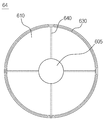
하나의 예로, 에어 커튼부(60)의 하나의 예시적인 저면 형상을 나타낸 도 4를 추가로 참조하면, 에어 커튼부(60)는 몸체부(610) 및 에어 분사 노즐부(620)를 포함하여 구성될 수 있다.As an example, referring to FIG. 4 showing one exemplary bottom surface shape of the
몸체부(610)는 처리 용기(20)의 개구부의 형상에 대응하는 형상을 가질 수 있다. 즉, 개구부가 원형인 경우, 몸체부(610)도 이에 대응하는 원형의 형상을 갖도록 구성될 수 있다.The
예를 들어, 이러한 몸체부(610)는 그 가장자리 영역이 중앙 영역에 비하여 처리 용기(20)의 개구부를 향하여 경사진 형상을 갖도록 구성될 수 있다. 이러한 구성에 따르면, 처리 용기(20)의 케미컬 퓸이 처리 용기(20)를 벗어나 챔버(10) 공간을 확산되는 문제를 방지하는 동시에, 케미컬 퓸을 처리 용기(20)의 바닥부에 형성되어 있는 케미컬 퓸 배출 유로(70)로 유도하여 챔버(10) 외부로 효과적으로 배출시킬 수 있다.For example, the
에어 분사 노즐부(620)는 몸체부(610)의 가장자리를 따라 에어 커튼을 형성하기 위한 에어가 분사되는 복수의 노즐로 구성된다.The air
도 4의 도면부호 605는 도시하지 않은 에어 공급유로를 통해 공급되는 에어가 일시적으로 모여 저장되는 공간이며, 도면부호 640은 에어를 에어 분사 노즐부(620)를 구성하는 각각이 노즐들로 공급하는 유로들이다.
다른 예로, 에어 커튼부(60)의 다른 예시적인 저면 형상을 나타낸 도 5를 추가로 참조하면, 에어 커튼부(60)는 몸체부(610) 및 에어 분사 슬릿부(630)를 포함하여 구성될 수 있다.As another example, further referring to FIG. 5 showing another exemplary bottom surface shape of the
몸체부(610)는 처리 용기(20)의 개구부의 형상에 대응하는 형상을 가지며, 도 4를 통해 설명한 예시적인 구조와 동일한 구조를 가질 수 있다. 도 5에 예시된 몸체부(610)도 그 가장자리 영역이 중앙 영역에 비하여 처리 용기(20)의 개구부를 향하여 경사진 형상을 갖도록 구성될 수 있다.The
에어 분사 슬릿부(630)는 몸체부(610)의 가장자리를 따라 슬릿 형상으로 구비되어 에어 커튼을 형성하기 위한 에어가 분사되는 구성요소이다.The air injection slit
도 5의 도면부호 605는 도시하지 않은 에어 공급유로를 통해 공급되는 에어가 일시적으로 모여 저장되는 공간이며, 도면부호 640은 에어를 에어 분사 슬릿부(630)로 공급하는 유로들이다.
도 4에 예시된 에어 분사 노즐부(620)는 몸체부(610)의 가장자리를 따라 배열되어 있는 복수의 노즐들을 통해 에어 커튼을 형성하기 위한 에어를 분사하도록 구성되는 반면, 도 5에 예시된 에어 분사 슬릿부(630)는 몸체부(610)의 가장자리를 따라 연속적인 슬릿 형상으로 구비되며, 이와 같은 연속적인 슬릿 형상을 갖는 에어 분사 슬릿부(630)를 통해 에어를 분사하면, 그에 대응하여 연속적인 에어 커튼이 형성될 수 있다.The air
예를 들어, 에어 커튼부(60)와 케미컬 분사부(50)는 일체로 사출 성형되거나, 에어 커튼부(60)와 케미컬 분사부(50)는 별도 제작후 상호 결합되어 일체화되도록 구성될 수 있다.For example, the
이상에서 상세히 설명한 바와 같이 본 발명에 따르면, 반도체 공정의 에칭 또는 세정 과정에서 발생하는 케미컬 퓸(chemical fume)을 에어 커튼을 이용하여 차단한 상태에서 외부로 배출시킴으로써 케미컬 퓸이 처리 용기 외부의 챔버 영역으로 확산되어 챔버 내부를 오염시키는 문제를 방지할 수 있는 에어 커튼을 이용한 케미컬 퓸 제거장치가 제공되는 효과가 있다.As described in detail above, according to the present invention, the chemical fume generated during the etching or cleaning process of a semiconductor process is discharged to the outside by blocking it using an air curtain, so that the chemical fume is located in the chamber area outside the processing container. It is effective to provide a chemical fume removal device using an air curtain that can prevent the problem of contaminating the inside of the chamber by diffusing.
W: 기판
10: 챔버
20: 처리 용기
30: 척
40: 기판 거치부
50: 케미컬 분사부
60: 에어 커튼부
70: 케미컬 퓸 배출 유로
610: 몸체부
620: 에어 분사 노즐부
630: 에어 분사 슬릿부W: Substrate
10: chamber
20: processing vessel
30: Chuck
40: substrate mounting portion
50: chemical injection
60: air curtain unit
70: chemical fume discharge flow path
610: body
620: air injection nozzle unit
630: air injection slit
Claims (9)
챔버 내부에 배치되어 있으며 상단에 개구부가 형성되어 있는 처리 용기;
상기 처리 용기 내부에 배치되어 있으며 처리 대상인 기판이 배치된 척;
상기 척에 배치된 기판에 케미컬을 분사하는 케미컬 분사부; 및
상기 처리 용기의 개구부에 에어 커튼을 형성하여 상기 케미컬 분사부에 의해 분사되는 케미컬에 의한 기판 처리 과정에서 발생하는 케미컬 퓸이 상기 처리 용기의 개구부를 통해 상기 처리 용기 외부의 챔버 공간으로 확산되는 것을 방지하는 에어 커튼부를 포함하는, 에어 커튼을 이용한 케미컬 퓸 제거장치.
As a chemical fume removal device using air curtain,
A processing container disposed inside the chamber and having an opening formed at the top;
A chuck disposed inside the processing container and on which a substrate to be processed is disposed;
A chemical jetting unit spraying chemicals on a substrate disposed on the chuck; And
An air curtain is formed in the opening of the processing container to prevent chemical fumes generated in the process of substrate processing by the chemical sprayed by the chemical spraying unit from being diffused into the chamber space outside the processing container through the opening of the processing container A chemical fume removal apparatus using an air curtain, comprising an air curtain section.
상기 에어 커튼부는 상기 처리 용기의 개구부 상부 공간을 상기 에어 커튼부의 하면부를 통해 차단하고 상기 처리 용기와 상기 에어 커튼부 사이에 존재하는 이격 공간을 상기 에어 커튼을 통해 차단하는 것을 특징으로 하는, 에어 커튼을 이용한 케미컬 퓸 제거장치.
According to claim 1,
The air curtain unit blocks an upper space of the opening of the processing container through a lower surface of the air curtain unit, and blocks a space between the processing container and the air curtain unit through the air curtain. Chemical fume removal device using.
상기 에어 커튼부는 상기 처리 용기의 개구부를 구성하는 상단 내면에 에어를 분사하여 상기 개구부를 차단하는 것을 특징으로 하는, 에어 커튼을 이용한 케미컬 퓸 제거장치.
According to claim 1,
The air curtain unit is a chemical fume removal apparatus using an air curtain, characterized in that to block the opening by injecting air to the upper inner surface constituting the opening of the processing container.
상기 에어 커튼부는
상기 개구부의 형상에 대응하는 형상을 갖는 몸체부; 및
상기 몸체부의 가장자리를 따라 상기 에어 커튼을 형성하기 위한 에어가 분사되는 복수의 노즐로 구성된 에어 분사 노즐부를 포함하는 것을 특징으로 하는, 에어 커튼을 이용한 케미컬 퓸 제거장치.
According to claim 1,
The air curtain unit
A body portion having a shape corresponding to the shape of the opening; And
And an air jet nozzle unit consisting of a plurality of nozzles through which air for forming the air curtain is formed along the edge of the body portion.
상기 에어 커튼부는
상기 개구부의 형상에 대응하는 형상을 갖는 몸체부; 및
상기 몸체부의 가장자리를 따라 슬릿 형상으로 구비되어 상기 에어 커튼을 형성하기 위한 에어가 분사되는 에어 분사 슬릿부를 포함하는 것을 특징으로 하는, 에어 커튼을 이용한 케미컬 퓸 제거장치.
According to claim 1,
The air curtain unit
A body portion having a shape corresponding to the shape of the opening; And
It is provided in a slit shape along the edge of the body portion, characterized in that it comprises an air injection slit portion for injecting air for forming the air curtain, chemical fume removal apparatus using an air curtain.
상기 몸체부는 가장자리 영역이 중앙 영역에 비하여 상기 처리 용기의 개구부를 향하여 경사진 형상을 갖는 것을 특징으로 하는, 에어 커튼을 이용한 케미컬 퓸 제거장치.
The method of claim 4 or 5,
The body portion is characterized in that the edge region has a shape inclined toward the opening of the processing vessel compared to the central region, chemical fume removal apparatus using an air curtain.
상기 에어 커튼부에 의해 상기 처리 용기의 내부로 억제되는 케미컬 퓸은 상기 처리 용기의 바닥부에 형성된 케미컬 퓸 배출 유로를 통해 상기 챔버의 외부로 배출되는 것을 특징으로 하는, 에어 커튼을 이용한 케미컬 퓸 제거장치.
According to claim 1,
The chemical fume suppressed into the inside of the processing container by the air curtain part is discharged to the outside of the chamber through the chemical fume discharge flow path formed at the bottom of the processing container, removing the chemical fume using the air curtain Device.
상기 에어 커튼부와 상기 케미컬 분사부는 일체로 사출 성형된 것을 특징으로 하는, 에어 커튼을 이용한 케미컬 퓸 제거장치.
According to claim 1,
The air curtain unit and the chemical injection unit characterized in that the injection molding integrally, chemical fume removal apparatus using an air curtain.
상기 에어 커튼부와 상기 케미컬 분사부는 별도 제작후 상호 결합되어 일체화된 것을 특징으로 하는, 에어 커튼을 이용한 케미컬 퓸 제거장치.
According to claim 1,
The air curtain unit and the chemical injection unit is separately manufactured and then combined with each other, characterized in that the integrated, chemical fume removal apparatus using an air curtain.
Priority Applications (2)
| Application Number | Priority Date | Filing Date | Title |
|---|---|---|---|
| KR1020180115733A KR102120704B1 (en) | 2018-09-28 | 2018-09-28 | Chemical fume removing apparatus using air curtain |
| PCT/KR2019/010145 WO2020067642A1 (en) | 2018-09-28 | 2019-08-12 | Device for removing chemical fume by using air curtain |
Applications Claiming Priority (1)
| Application Number | Priority Date | Filing Date | Title |
|---|---|---|---|
| KR1020180115733A KR102120704B1 (en) | 2018-09-28 | 2018-09-28 | Chemical fume removing apparatus using air curtain |
Publications (2)
| Publication Number | Publication Date |
|---|---|
| KR20200036282A true KR20200036282A (en) | 2020-04-07 |
| KR102120704B1 KR102120704B1 (en) | 2020-06-10 |
Family
ID=69952902
Family Applications (1)
| Application Number | Title | Priority Date | Filing Date |
|---|---|---|---|
| KR1020180115733A Active KR102120704B1 (en) | 2018-09-28 | 2018-09-28 | Chemical fume removing apparatus using air curtain |
Country Status (2)
| Country | Link |
|---|---|
| KR (1) | KR102120704B1 (en) |
| WO (1) | WO2020067642A1 (en) |
Cited By (1)
| Publication number | Priority date | Publication date | Assignee | Title |
|---|---|---|---|---|
| KR20240173030A (en) | 2023-06-02 | 2024-12-10 | 세메스 주식회사 | Chamber fluid collector and substrate treating apparatus |
Citations (6)
| Publication number | Priority date | Publication date | Assignee | Title |
|---|---|---|---|---|
| KR20060068455A (en) | 2004-12-16 | 2006-06-21 | 삼성전자주식회사 | Chuck cleaning device of transfer robot |
| KR20100006954U (en) | 2008-12-30 | 2010-07-08 | 주식회사 케이씨텍 | Contact cleaning device for large area substrates |
| KR20110041445A (en) * | 2011-02-07 | 2011-04-21 | 우범제 | Fume remover and semiconductor manufacturing device using same |
| KR20120004161A (en) * | 2010-07-06 | 2012-01-12 | 삼성전자주식회사 | Flux Pollutant Washer |
| KR20140147556A (en) * | 2013-06-20 | 2014-12-30 | 피에스케이 주식회사 | Unit and method for cooling, and apparatus and method for treating substrate |
| KR20170133771A (en) * | 2016-05-26 | 2017-12-06 | 세메스 주식회사 | Apparatus for Processing Substrate |
Family Cites Families (3)
| Publication number | Priority date | Publication date | Assignee | Title |
|---|---|---|---|---|
| JPH0811224B2 (en) * | 1992-03-09 | 1996-02-07 | 三宝電機株式会社 | Article cleaning equipment |
| KR100814179B1 (en) * | 2000-06-27 | 2008-03-14 | 브룩스-피알아이 오토메이션(스윗질랜드) 게엠베하 | Cleaning device and method used in semiconductor device products |
| DE102011052325A1 (en) * | 2011-08-01 | 2013-02-07 | Roth & Rau Ag | Cleaning module and cleaning method for substrates and / or substrate carrier |
-
2018
- 2018-09-28 KR KR1020180115733A patent/KR102120704B1/en active Active
-
2019
- 2019-08-12 WO PCT/KR2019/010145 patent/WO2020067642A1/en not_active Ceased
Patent Citations (6)
| Publication number | Priority date | Publication date | Assignee | Title |
|---|---|---|---|---|
| KR20060068455A (en) | 2004-12-16 | 2006-06-21 | 삼성전자주식회사 | Chuck cleaning device of transfer robot |
| KR20100006954U (en) | 2008-12-30 | 2010-07-08 | 주식회사 케이씨텍 | Contact cleaning device for large area substrates |
| KR20120004161A (en) * | 2010-07-06 | 2012-01-12 | 삼성전자주식회사 | Flux Pollutant Washer |
| KR20110041445A (en) * | 2011-02-07 | 2011-04-21 | 우범제 | Fume remover and semiconductor manufacturing device using same |
| KR20140147556A (en) * | 2013-06-20 | 2014-12-30 | 피에스케이 주식회사 | Unit and method for cooling, and apparatus and method for treating substrate |
| KR20170133771A (en) * | 2016-05-26 | 2017-12-06 | 세메스 주식회사 | Apparatus for Processing Substrate |
Cited By (1)
| Publication number | Priority date | Publication date | Assignee | Title |
|---|---|---|---|---|
| KR20240173030A (en) | 2023-06-02 | 2024-12-10 | 세메스 주식회사 | Chamber fluid collector and substrate treating apparatus |
Also Published As
| Publication number | Publication date |
|---|---|
| WO2020067642A1 (en) | 2020-04-02 |
| KR102120704B1 (en) | 2020-06-10 |
Similar Documents
| Publication | Publication Date | Title |
|---|---|---|
| CN100490083C (en) | Substrate processing method and substrate processing apparatus | |
| TWI709169B (en) | Substrate processing method and substrate processing apparatus | |
| KR100725108B1 (en) | Gas supply apparatus and substrate processing apparatus having the same | |
| US8607807B2 (en) | Liquid treatment apparatus and method | |
| KR102208292B1 (en) | Substrate processing apparatus and substrate processing method | |
| US20130167876A1 (en) | Substrate processing apparatus and substrate processing method | |
| TWI631996B (en) | Substrate processing method and substrate processing device | |
| CN110660647A (en) | Substrate processing apparatus and substrate processing method | |
| CN100380602C (en) | Substrate processing method and substrate processing device | |
| KR20180054598A (en) | Substrate processing method, substrate processing apparatus, and storage medium | |
| KR100808237B1 (en) | Surface treatment method of object by transition flow | |
| KR20220047517A (en) | Substrate processing apparatus | |
| KR20180045653A (en) | Substrate treating apparatus, process fluid treating apparatus and ozone decomposition method | |
| KR102120704B1 (en) | Chemical fume removing apparatus using air curtain | |
| KR20180034229A (en) | Substrate processing method and substrate processing apparatus | |
| KR102885017B1 (en) | Substrate processing method | |
| CN111656493B (en) | Substrate processing equipment | |
| KR102120705B1 (en) | Chemical fume removing apparatus using integrated local nozzle | |
| TWI673115B (en) | Substrate processing apparatus and substrate processing method | |
| KR102415323B1 (en) | Nozzle unit and apparatus for treating substrate | |
| JP2005244130A (en) | Method and apparatus for processing substrate | |
| KR101398436B1 (en) | Method and apparatus for cleaning the lower part of a substrate | |
| KR20130135792A (en) | Method and system for rapid mixing of process chemicals using an injection nozzle | |
| KR20100055812A (en) | Apparatus for processing a substrate | |
| JP2005166848A (en) | Substrate treating method and device |
Legal Events
| Date | Code | Title | Description |
|---|---|---|---|
| PA0109 | Patent application |
St.27 status event code: A-0-1-A10-A12-nap-PA0109 |
|
| PA0201 | Request for examination |
St.27 status event code: A-1-2-D10-D11-exm-PA0201 |
|
| PE0902 | Notice of grounds for rejection |
St.27 status event code: A-1-2-D10-D21-exm-PE0902 |
|
| E13-X000 | Pre-grant limitation requested |
St.27 status event code: A-2-3-E10-E13-lim-X000 |
|
| P11-X000 | Amendment of application requested |
St.27 status event code: A-2-2-P10-P11-nap-X000 |
|
| P13-X000 | Application amended |
St.27 status event code: A-2-2-P10-P13-nap-X000 |
|
| PG1501 | Laying open of application |
St.27 status event code: A-1-1-Q10-Q12-nap-PG1501 |
|
| E701 | Decision to grant or registration of patent right | ||
| PE0701 | Decision of registration |
St.27 status event code: A-1-2-D10-D22-exm-PE0701 |
|
| GRNT | Written decision to grant | ||
| PR0701 | Registration of establishment |
St.27 status event code: A-2-4-F10-F11-exm-PR0701 |
|
| PR1002 | Payment of registration fee |
St.27 status event code: A-2-2-U10-U11-oth-PR1002 Fee payment year number: 1 |
|
| PG1601 | Publication of registration |
St.27 status event code: A-4-4-Q10-Q13-nap-PG1601 |
|
| PN2301 | Change of applicant |
St.27 status event code: A-5-5-R10-R11-asn-PN2301 |
|
| PN2301 | Change of applicant |
St.27 status event code: A-5-5-R10-R14-asn-PN2301 |
|
| PR1001 | Payment of annual fee |
St.27 status event code: A-4-4-U10-U11-oth-PR1001 Fee payment year number: 4 |
|
| PR1001 | Payment of annual fee |
St.27 status event code: A-4-4-U10-U11-oth-PR1001 Fee payment year number: 5 |
|
| PR1001 | Payment of annual fee |
St.27 status event code: A-4-4-U10-U11-oth-PR1001 Fee payment year number: 6 |
|
| P22-X000 | Classification modified |
St.27 status event code: A-4-4-P10-P22-nap-X000 |