KR20200028111A - Egr cooler - Google Patents
Egr cooler Download PDFInfo
- Publication number
- KR20200028111A KR20200028111A KR1020180106351A KR20180106351A KR20200028111A KR 20200028111 A KR20200028111 A KR 20200028111A KR 1020180106351 A KR1020180106351 A KR 1020180106351A KR 20180106351 A KR20180106351 A KR 20180106351A KR 20200028111 A KR20200028111 A KR 20200028111A
- Authority
- KR
- South Korea
- Prior art keywords
- core
- exhaust gas
- inlet
- core assembly
- outlet
- Prior art date
Links
Images


Classifications
-
- F—MECHANICAL ENGINEERING; LIGHTING; HEATING; WEAPONS; BLASTING
- F02—COMBUSTION ENGINES; HOT-GAS OR COMBUSTION-PRODUCT ENGINE PLANTS
- F02M—SUPPLYING COMBUSTION ENGINES IN GENERAL WITH COMBUSTIBLE MIXTURES OR CONSTITUENTS THEREOF
- F02M26/00—Engine-pertinent apparatus for adding exhaust gases to combustion-air, main fuel or fuel-air mixture, e.g. by exhaust gas recirculation [EGR] systems
- F02M26/13—Arrangement or layout of EGR passages, e.g. in relation to specific engine parts or for incorporation of accessories
- F02M26/22—Arrangement or layout of EGR passages, e.g. in relation to specific engine parts or for incorporation of accessories with coolers in the recirculation passage
- F02M26/23—Layout, e.g. schematics
-
- F—MECHANICAL ENGINEERING; LIGHTING; HEATING; WEAPONS; BLASTING
- F02—COMBUSTION ENGINES; HOT-GAS OR COMBUSTION-PRODUCT ENGINE PLANTS
- F02M—SUPPLYING COMBUSTION ENGINES IN GENERAL WITH COMBUSTIBLE MIXTURES OR CONSTITUENTS THEREOF
- F02M26/00—Engine-pertinent apparatus for adding exhaust gases to combustion-air, main fuel or fuel-air mixture, e.g. by exhaust gas recirculation [EGR] systems
- F02M26/13—Arrangement or layout of EGR passages, e.g. in relation to specific engine parts or for incorporation of accessories
- F02M26/22—Arrangement or layout of EGR passages, e.g. in relation to specific engine parts or for incorporation of accessories with coolers in the recirculation passage
- F02M26/29—Constructional details of the coolers, e.g. pipes, plates, ribs, insulation or materials
- F02M26/30—Connections of coolers to other devices, e.g. to valves, heaters, compressors or filters; Coolers characterised by their location on the engine
-
- F—MECHANICAL ENGINEERING; LIGHTING; HEATING; WEAPONS; BLASTING
- F01—MACHINES OR ENGINES IN GENERAL; ENGINE PLANTS IN GENERAL; STEAM ENGINES
- F01P—COOLING OF MACHINES OR ENGINES IN GENERAL; COOLING OF INTERNAL-COMBUSTION ENGINES
- F01P3/00—Liquid cooling
- F01P3/12—Arrangements for cooling other engine or machine parts
-
- F—MECHANICAL ENGINEERING; LIGHTING; HEATING; WEAPONS; BLASTING
- F02—COMBUSTION ENGINES; HOT-GAS OR COMBUSTION-PRODUCT ENGINE PLANTS
- F02F—CYLINDERS, PISTONS OR CASINGS, FOR COMBUSTION ENGINES; ARRANGEMENTS OF SEALINGS IN COMBUSTION ENGINES
- F02F1/00—Cylinders; Cylinder heads
- F02F1/02—Cylinders; Cylinder heads having cooling means
- F02F1/10—Cylinders; Cylinder heads having cooling means for liquid cooling
-
- F—MECHANICAL ENGINEERING; LIGHTING; HEATING; WEAPONS; BLASTING
- F02—COMBUSTION ENGINES; HOT-GAS OR COMBUSTION-PRODUCT ENGINE PLANTS
- F02M—SUPPLYING COMBUSTION ENGINES IN GENERAL WITH COMBUSTIBLE MIXTURES OR CONSTITUENTS THEREOF
- F02M26/00—Engine-pertinent apparatus for adding exhaust gases to combustion-air, main fuel or fuel-air mixture, e.g. by exhaust gas recirculation [EGR] systems
- F02M26/13—Arrangement or layout of EGR passages, e.g. in relation to specific engine parts or for incorporation of accessories
- F02M26/22—Arrangement or layout of EGR passages, e.g. in relation to specific engine parts or for incorporation of accessories with coolers in the recirculation passage
- F02M26/29—Constructional details of the coolers, e.g. pipes, plates, ribs, insulation or materials
- F02M26/32—Liquid-cooled heat exchangers
-
- F—MECHANICAL ENGINEERING; LIGHTING; HEATING; WEAPONS; BLASTING
- F28—HEAT EXCHANGE IN GENERAL
- F28D—HEAT-EXCHANGE APPARATUS, NOT PROVIDED FOR IN ANOTHER SUBCLASS, IN WHICH THE HEAT-EXCHANGE MEDIA DO NOT COME INTO DIRECT CONTACT
- F28D9/00—Heat-exchange apparatus having stationary plate-like or laminated conduit assemblies for both heat-exchange media, the media being in contact with different sides of a conduit wall
- F28D9/0031—Heat-exchange apparatus having stationary plate-like or laminated conduit assemblies for both heat-exchange media, the media being in contact with different sides of a conduit wall the conduits for one heat-exchange medium being formed by paired plates touching each other
- F28D9/0043—Heat-exchange apparatus having stationary plate-like or laminated conduit assemblies for both heat-exchange media, the media being in contact with different sides of a conduit wall the conduits for one heat-exchange medium being formed by paired plates touching each other the plates having openings therein for circulation of at least one heat-exchange medium from one conduit to another
-
- F—MECHANICAL ENGINEERING; LIGHTING; HEATING; WEAPONS; BLASTING
- F01—MACHINES OR ENGINES IN GENERAL; ENGINE PLANTS IN GENERAL; STEAM ENGINES
- F01P—COOLING OF MACHINES OR ENGINES IN GENERAL; COOLING OF INTERNAL-COMBUSTION ENGINES
- F01P3/00—Liquid cooling
- F01P3/02—Arrangements for cooling cylinders or cylinder heads
- F01P2003/021—Cooling cylinders
-
- F—MECHANICAL ENGINEERING; LIGHTING; HEATING; WEAPONS; BLASTING
- F01—MACHINES OR ENGINES IN GENERAL; ENGINE PLANTS IN GENERAL; STEAM ENGINES
- F01P—COOLING OF MACHINES OR ENGINES IN GENERAL; COOLING OF INTERNAL-COMBUSTION ENGINES
- F01P2060/00—Cooling circuits using auxiliaries
- F01P2060/16—Outlet manifold
-
- F—MECHANICAL ENGINEERING; LIGHTING; HEATING; WEAPONS; BLASTING
- F01—MACHINES OR ENGINES IN GENERAL; ENGINE PLANTS IN GENERAL; STEAM ENGINES
- F01P—COOLING OF MACHINES OR ENGINES IN GENERAL; COOLING OF INTERNAL-COMBUSTION ENGINES
- F01P3/00—Liquid cooling
- F01P3/02—Arrangements for cooling cylinders or cylinder heads
Landscapes
- Engineering & Computer Science (AREA)
- Mechanical Engineering (AREA)
- General Engineering & Computer Science (AREA)
- Chemical & Material Sciences (AREA)
- Combustion & Propulsion (AREA)
- Physics & Mathematics (AREA)
- Thermal Sciences (AREA)
- Exhaust-Gas Circulating Devices (AREA)
Abstract
Description
본 발명은 이지알 쿨러에 관한 것으로, 더욱 상세하게는 실린더 블록에 설치되는 이지알 쿨러에 관한 것이다. The present invention relates to an easy cooler, and more particularly, to an easy cooler installed on a cylinder block.
차량에서 배출되는 배기가스에 포함된 질소산화물(nitrous oxide; NOx)은 주요한 대기오염물질로 규제되고 있으며, 이러한 NOx의 배출을 줄이기 위한 많은 연구가 진행되고 있다.Nitrogen oxide (NOx) contained in exhaust gas emitted from vehicles is regulated as a major air pollutant, and many studies have been conducted to reduce the emission of NOx.
배기가스 재순환(exhaust gas recirculation; EGR) 시스템은 유해 배기가스의저감을 위해 차량에 장착되는 시스템이다. 일반적으로, NOx는 혼합기 중에 공기의 비율이 높아서 연소가 잘될 때 증가한다. 따라서, 배기가스 재순환 시스템은 엔진에서 배출되는 배기가스의 일부(예를 들어 5~20%)를 다시 혼합기에 섞어 혼합기 속의 산소량을 줄이고 연소를 방해하여 NOx의 발생을 억제하는 시스템이다.An exhaust gas recirculation (EGR) system is a system mounted on a vehicle to reduce harmful exhaust gas. In general, NOx increases when the combustion rate is good due to the high proportion of air in the mixer. Therefore, the exhaust gas recirculation system is a system that suppresses the generation of NOx by reducing the amount of oxygen in the mixer and preventing combustion by mixing a part (for example, 5 to 20%) of exhaust gas emitted from the engine again into the mixer.
가솔린 엔진의 배기가스 재순환(exhaust gas recirculation; EGR) 시스템은 연비 개선을 위해 차량에 장착되는 시스템이다. 배기가스 재순환 시스템을 통해 저속/저부하 영역에서 펌핑 로스 저감시킬 수 있고, 중속/중부하 영역에서 연소실(21)의 온도 저감에 의한 점화 시기 진각시킬 수 있기 때문에 차량의 연비를 개선할 수 있다.The exhaust gas recirculation (EGR) system of a gasoline engine is a system mounted on a vehicle to improve fuel efficiency. Through the exhaust gas recirculation system, it is possible to reduce the pumping loss in the low / low load region, and improve the fuel efficiency of the vehicle because the ignition timing by reducing the temperature of the
대표적인 배기가스 재순환 시스템으로 저압 이지알(LP-EGR: low pressure exhaust gas recirculation) 장치가 있다. 저압 EGR 장치는 터보차저(70)의 터빈(71)을 통과한 배기가스를 컴프레서(72) 전단의 흡기 통로로 재순환시킨다. A typical exhaust gas recirculation system is a low pressure exhaust gas recirculation (LP-EGR) device. The low-pressure EGR device recirculates the exhaust gas that has passed through the
배기가스 재순환 시스템에는 쿨러가 포함되는데, 쿨러에 의해 재순환되는 배기가스를 냉각시켜 연소실(21)로 공급한다. The exhaust gas recirculation system includes a cooler, which cools the exhaust gas recirculated by the cooler and supplies it to the
종래 기술에 의한 이지알 쿨러는 별도의 하우징 내부에 냉각 구조를 설치하고, 하우징의 외부에는 재순환 가스가 흐르는 재순환 라인(52)을 연결하기 위한 니플(nipple) 등의 다양한 부품이 필요하고, 재순환 라인(52)의 길이 증가하여 차량의 제조 원가가 증가한다. Easy cooler according to the prior art installs a cooling structure inside a separate housing, and various parts such as nipples for connecting a
또한, 이지알 쿨러를 차량 내부에 견고하는 것이 어렵기 때문에, 차량에 주행하면서 이지알 쿨러 하우징이 떨리면서 과다한 진동이 발생하는 문제가 발생한다. In addition, since it is difficult to secure the YG cooler inside the vehicle, there is a problem that excessive vibration occurs while the YG cooler housing shakes while driving in the vehicle.
이 배경기술 부분에 기재된 사항은 발명의 배경에 대한 이해를 증진하기 위하여 작성된 것으로서, 이 기술이 속하는 분야에서 통상의 지식을 가진 자에게 이미 알려진 종래기술이 아닌 사항을 포함할 수 있다.The items described in this background section are written to improve the understanding of the background of the invention, and may include matters not known in the prior art that are already known to those skilled in the art.
본 발명은 상기한 바와 같은 문제점을 해결하기 위한 것으로, 차량의 제조 원가를 절감할 수 있는 이지알 쿨러를 제공하는 것을 목적으로 한다. The present invention is to solve the above problems, and an object of the present invention is to provide an easy cooler capable of reducing the manufacturing cost of a vehicle.
또한, 차량에 주행 중에 발생하는 진동을 저감시킬 수 있는 이지알 쿨러를 제공하는 것을 또 다른 목적으로 한다. Another object of the present invention is to provide an easy cooler capable of reducing vibration generated during driving in a vehicle.
상기한 바와 같은 목적을 달성하기 위한 본 발명의 실시예에 따른 이지알 쿨러는 장착 공간이 형성되고 냉각수가 유입되는 냉각수 유입구가 형성되는 실린더 블록; 상기 장착 공간에 설치되고, 배기가스가 유입되는 상부 코어 유입구와 배기가스가 유출되는 상부 코어 유출구가 형성되는 상부 코어, 및 배기가스가 유입되는 하부 코어 유입구와 배기가스가 유출되는 하부 코어 유출구가 형성되는 하부 코어가 결합되어 배기가스가 흐르는 유로가 형성되는 적어도 하나의 코어 조립체; 및 상기 코어 조립체가 장착된 상기 장착 공간을 차단하고, 배기가스가 유입되는 커버 유입구와 배기가스가 유출되는 커버 유출구, 및 상기 냉각수가 배출되는 냉각수 유출구가 형성되는 커버 플레이트;를 포함할 수 있다.Easy cooler according to an embodiment of the present invention for achieving the above object is provided with a mounting space and a cylinder block in which a coolant inlet through which coolant flows is formed; The upper core is formed in the mounting space, the upper core inlet through which the exhaust gas flows, the upper core through which the upper core outlet through which the exhaust gas flows, and the lower core inlet through which the exhaust gas flows and the lower core outlet through which the exhaust gas flows are formed. At least one core assembly in which a lower core to be coupled is formed to form a flow path through which exhaust gas flows; And a cover plate blocking the mounting space in which the core assembly is mounted, a cover inlet through which exhaust gas is introduced, a cover outlet through which exhaust gas is discharged, and a cooling water outlet through which the cooling water is discharged.
상기 코어 조립체는 상기 장착 공간에 복수 개가 순차적으로 적층되고, 상기 장착 공간의 내측면과 상기 코어 조립체의 사이, 및 상기 복수 개의 코어 조립체의 사이, 및 상기 커버 플레이트와 상기 코어 조립체의 사이에는 상기 냉각수가 흐르는 냉각수 유로가 형성될 수 있다. The core assembly is a plurality of sequentially stacked in the mounting space, the coolant between the inner surface of the mounting space and the core assembly, and between the plurality of core assemblies, and between the cover plate and the core assembly Cooling water flow path may be formed.
상기 실린더 블록의 상면과 상기 커버 플레이트 사이에 구비되는 가스켓;을 더 포함할 수 있다. Gasket provided between the upper surface of the cylinder block and the cover plate; may further include.
상기 상부 코어 또는 상기 하부 코어의 내측면에는 내측 핀이 구비될 수 있다.An inner pin may be provided on the inner surface of the upper core or the lower core.
상기 상부 코어 또는 상기 하부 코어의 외측면에는 외측 핀이 구비될 수 있다.An outer pin may be provided on the outer surface of the upper core or the lower core.
상기 코어 조립체는 상기 장착 공간에 복수 개가 순차적으로 장착되고, 상기 어느 하나의 코어 조립체의 하부 코어 유입구와 상기 어느 하나의 코어 조립체와 인접한 다른 하나의 코어 조립체의 상부 코어 유입구는 서로 밀착되어 연통하고, 상기 어느 하나의 코어 조립체의 상부 코어 유출구와 상기 어느 하나의 코어 조립체와 인접한 다른 하나의 코어 조립체의 하부 코어 유출구는 서로 밀착되어 연통할 수 있다.The core assembly is a plurality of sequentially mounted in the mounting space, the lower core inlet of either one of the core assembly and the upper core inlet of the other core assembly adjacent to the one of the core assembly is in close communication with each other, The upper core outlet of the one core assembly and the lower core outlet of the other core assembly adjacent to the one core assembly may be in close communication with each other.
상기 커버 플레이트의 커버 유입구에는 상기 코어 조립체 내부의 상기 배기가스 유로로 유입되는 배기가스를 안내하는 입구 브라켓;을 더 포함하고, 상기 입구 브라켓은 하면이 개방된 육면체 모양으로 형성되고, 상기 입구 브라켓의 상면에는 배기가스가 유입되는 통공이 형성되며, 상기 입구 브라켓의 상면은 상기 코어에 형성되는 상기 배기가스 유로를 향하여 일정 각도 경사지도록 형성될 수 있다.The cover inlet of the cover plate further includes an inlet bracket for guiding exhaust gas flowing into the exhaust gas flow path inside the core assembly, and the inlet bracket is formed in a hexahedral shape with a lower surface open, and the inlet bracket A through hole through which exhaust gas flows is formed on an upper surface, and an upper surface of the inlet bracket may be formed to be inclined at an angle toward the exhaust gas flow path formed in the core.
상기 커버 플레이트의 커버 유출구에는 상기 코어 조립체 내부의 상기 배기가스 유로에서 유출되는 배기가스를 안내하는 출구 브라켓;을 더 포함하고, 상기 출구 브라켓은 상면과 하면이 개방된 원통 형상으로 형성될 수 있다.The cover outlet of the cover plate may further include an outlet bracket for guiding exhaust gas flowing out of the exhaust gas flow path inside the core assembly, and the outlet bracket may be formed in a cylindrical shape with upper and lower surfaces open.
상기 커버 플레이트의 외곽에는 상기 실린더 블록의 반대쪽 방향으로 절곡된 리브가 형성될 수 있다.A rib bent in a direction opposite to the cylinder block may be formed on an outer side of the cover plate.
상기 상부 코어 유입구의 주변에는 상기 코어 조립체의 외측으로 돌출되는 상부 유입구 플랜지가 형성되고, 상기 상부 코어 유출구의 주변에는 상기 코어 조립체의 외측으로 돌출되는 상부 유출구 플랜지가 형성되며, 상기 하부 코어 유입구의 주변에는 상기 코어 조립체의 외측으로 돌출되는 하부 유입구 플랜지가 형성되고, 상기 하부 코어 유출구의 주변에는 상기 코어 조립체의 외측으로 돌출되는 하부 유출구 플랜지가 형성될 수 있다.An upper inlet flange protruding outward of the core assembly is formed around the upper core inlet, and an upper outlet flange protruding outwardly of the core assembly is formed around the upper core outlet, and around the lower core inlet. A lower inlet flange protruding outward of the core assembly may be formed, and a lower outlet flange protruding outwardly of the core assembly may be formed around the lower core outlet.
어느 하나의 상기 코어 조립체에 형성되는 상기 상부 유입구 플랜지는 상기 어느 하나의 상기 코어 조립체와 인접한 다른 하나의 상기 코어 조립체에 형성되는 상기 하부 유입구 플랜지와 밀착되고, 상기 어느 하나의 상기 코어 조립체에 형성되는 상기 상부 유출구 플랜지는 상기 어느 하나의 상기 코어 조립체와 인접한 상기 다른 하나의 상기 코어 조립체에 형성되는 상기 하부 유출구 플랜지와 밀착되어, 상기 어느 하나의 코어 조립체와 인접한 상기 다른 하나의 코어 조립체의 사이에 냉각수가 흐르는 상기 냉각수 유로가 형성될 수 있다.The upper inlet flange formed in one of the core assemblies is in close contact with the lower inlet flange formed in the other one of the core assembly adjacent to the one of the core assembly, and is formed in the one of the core assembly The upper outlet flange is in close contact with the lower outlet flange formed in the other one of the core assembly adjacent to the one of the core assembly, the coolant between the other core assembly adjacent to the one core assembly The cooling water flow path through which may flow may be formed.
상기한 바와 같은 본 발명의 실시예에 의한 이지알 쿨러에 의하면, 이지알 쿨러가 실린더 블록 내부에 냉각수와 배기가스가 열 교환되는 냉각 구조를 설치함으로써, 이지알 쿨러의 구성을 단순화할 수 있고, 이로 인해, 차량의 제조 원가를 절감할 수 있다. According to the easy cooler according to the embodiment of the present invention as described above, the easy cooler can simplify the configuration of the easy cooler by providing a cooling structure in which the coolant and the exhaust gas are heat exchanged inside the cylinder block. For this reason, the manufacturing cost of a vehicle can be reduced.
또한, 이지알 쿨러를 실린더 블록에 형성함으로써, 차량의 주행시 이지알 쿨러의 떨림에 의해 진동이 발생하는 것을 방지할 수 있다. Further, by forming the easy cooler on the cylinder block, it is possible to prevent the vibration from being generated by the vibration of the easy cooler when the vehicle is running.
이 도면들은 본 발명의 예시적인 실시예를 설명하는데 참조하기 위함이므로, 본 발명의 기술적 사상을 첨부한 도면에 한정해서 해석하여서는 아니된다.
도 1은 본 발명의 실시예에 따른 이지알 쿨러가 적용되는 엔진 시스템의 구성을 도시한 도면이다.
도 2는 본 발명의 실시예에 따른 실린더 블록의 구성을 도시한 부분 사시도이다.
도 3은 본 발명의 실시예에 따른 이지알 쿨러를 도시한 일부 절개 사시도이다.
도 4는 본 발명의 실시예에 따른 복수의 코어와 커버 플레이트를 도시한 사시도이다.
도 5은 본 발명의 실시예에 따른 코어의 구성을 도시한 도면이다.
도 6은 본 발명의 실시예에 따른 커버 플레이트의 구성을 도시한 도면이다.
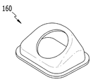
도 7은 본 발명의 실시예에 따른 입구 브라켓의 구성을 도시한 도면이다.
도 8는 본 발명의 실시예에 따른 출구 브라켓의 구성을 도시한 도면이다.Since these drawings are for reference to explain exemplary embodiments of the present invention, the technical spirit of the present invention should not be construed as being limited to the accompanying drawings.
1 is a view showing the configuration of an engine system to which an easy cooler is applied according to an embodiment of the present invention.
Figure 2 is a partial perspective view showing the configuration of a cylinder block according to an embodiment of the present invention.
3 is a partially cut-away perspective view showing an easy cooler according to an embodiment of the present invention.
4 is a perspective view showing a plurality of cores and cover plates according to an embodiment of the present invention.
5 is a view showing the configuration of a core according to an embodiment of the present invention.
6 is a view showing the configuration of a cover plate according to an embodiment of the present invention.
7 is a view showing the configuration of the inlet bracket according to an embodiment of the present invention.
8 is a view showing the configuration of the outlet bracket according to an embodiment of the present invention.
첨부한 도면을 참고로 하여 본 발명의 실시예에 대하여 본 발명이 속하는 기술 분야에서 통상의 지식을 가진 자가 용이하게 실시할 수 있도록 상세히 설명한다. 그러나 본 발명은 여러 가지 상이한 형태로 구현될 수 있으며 여기에서 설명하는 실시예에 한정되지 않는다.The embodiments of the present invention will be described in detail with reference to the accompanying drawings so that those skilled in the art to which the present invention pertains can easily practice. However, the present invention can be implemented in many different forms and is not limited to the embodiments described herein.
본 발명을 명확하게 설명하기 위해서 설명과 관계없는 부분은 생략하였으며, 명세서 전체를 통하여 동일 또는 유사한 구성요소에 대해서는 동일한 참조 부호를 붙이도록 한다.In order to clearly describe the present invention, parts irrelevant to the description are omitted, and the same reference numerals are assigned to the same or similar elements throughout the specification.
또한, 도면에서 나타난 각 구성의 크기 및 두께는 설명의 편의를 위해 임의로 나타내었으므로, 본 발명이 반드시 도면에 도시된 바에 한정되지 않으며, 여러 부분 및 영역을 명확하게 표현하기 위하여 두께를 확대하여 나타내었다.In addition, since the size and thickness of each component shown in the drawings are arbitrarily shown for convenience of description, the present invention is not necessarily limited to that shown in the drawings, and the thickness is enlarged to clearly express various parts and regions. Did.
먼저, 도 1을 참조하여 본 발명의 실시 예에 따른 이지알 쿨러가 적용되는 엔진 시스템의 구성에 대하여 설명한다. First, the configuration of the engine system to which the easy cooler according to an embodiment of the present invention is applied will be described with reference to FIG. 1.
도 1은 본 발명의 실시예에 따른 이지알 쿨러가 적용되는 엔진 시스템의 구성을 도시한 도면이다. 1 is a view showing the configuration of an engine system to which an easy cooler is applied according to an embodiment of the present invention.
도 1에 도시된 바와 같이, 본 발명의 실시예에 의한 이지알 쿨러(100)가 적용되는 엔진 시스템은 엔진(20), 및 배기가스 재순환 장치(50)를 포함할 수 있다. 1, the engine system to which the
엔진(20)은 연료의 연소에 의해 차량의 주행에 필요한 동력을 발생시키는 복수의 연소실(21)을 포함하고, 상기 엔진(20)에는 상기 연소실(21)로 공급되는 흡기 가스가 흐르는 흡기 라인(10)과, 상기 연소실(21)에서 배출되는 배기가스가 흐르는 배기 라인(40)이 구비된다.The
상기 배기 라인(40)에는 상기 연소실(21)에서 배출되는 배기가스에 포함된 각종 유해 물질을 정화시키는 배기가스 정화 장치(60)가 구비된다. 상기 배기가스 정화 장치(60)는 질소 산화물을 정화하기 위한 LNT(lean NOx trap), 디젤 산화 촉매(diesel oxidation catalyst) 및 디젤 매연 필터(diesel particulate filter)를 포함할 수 있다.The
본 발명의 엔진 시스템은 상기 연소실(21)로 공급되는 흡기를 압축하는 터보차저(70)를 더 포함할 수 있다. The engine system of the present invention may further include a
상기 터보차저(70)는 상기 흡기 라인(10)을 통해 유입되는 흡기 가스(외기+재순환 가스)를 압축하여 상기 연소실(21)로 공급한다. 상기 터보차저(70)는 상기 배기 라인(40)에 구비되고 상기 연소실(21)(21)에서 배출되는 배기가스에 의해 회전하는 터빈(71), 및 상기 터빈(71)과 연동하여 회전하고 흡기 가스를 압축하는 컴프레서(72)를 포함한다.The
배기가스 재순환 장치(50)는 재순환 라인(52), 이지알 쿨러(100), 및 이지알 밸브(54)를 포함한다. The exhaust
상기 재순환 라인(52)은 상기 터빈(71) 하류의 배기 라인(40)에서 분기되어 상기 컴프레서(72) 상류의 흡기 라인(10)으로 합류한다. 상기 이지알 쿨러(100)는 상기 이지알 라인에 배치되고, 상기 재순환 라인(52)을 흐르는 배기가스를 냉각시킨다. 상기 이지알 밸브(54)는 상기 이지알 라인과 상기 흡기 라인(10)이 합류하는 지점에 배치되고, 상기 흡기 라인(10)으로 유입되는 재순환 가스량을 조절한다. 여기서, 상기 재순환 라인(52)을 통해 상기 흡기 라인(10)으로 공급되는 배기가스를 재순환 가스라고 한다.The
본 명세서에서 배기가스 재순환 장치(50)는 저압 이지알 장치(low pressure exhaust gas recirculation apparatus)를 예로 들어 설명한다. 그러나 본 발명의 권리 범위가 이에 한정되는 것은 아니며, 고압 이지알 장치(high pressure exhaust gas recirculation apparatus)에도 적용될 수 있음은 물론이다. In the present specification, the exhaust
이하에서는 본 발명의 실시예에 의한 이지알 쿨러에 대하여 첨부된 도면을 참조하여 상세하게 설명한다.Hereinafter, an easy cooler according to an embodiment of the present invention will be described in detail with reference to the accompanying drawings.
본 발명의 실시 예에 따른 이지알 쿨러(100)는 실린더 블록(30), 실린더 블록(30)의 장착 공간(31)에 설치되는 복수의 코어 조립체(110), 및 상기 코어 조립체(110)가 설치되는 장착 공간(31)을 덮는 커버 플레이트(150)를 포함할 수 있다.
도 2는 본 발명의 실시예에 따른 실린더 블록(30)의 구성을 도시한 부분 사시도이다. 2 is a partial perspective view showing the configuration of a
도 2에 도시된 바와 같이, 상기 실린더 블록(30)의 내부에는 상기 복수의 연소실(21)이 형성되고, 외측에 상기 장착 공간(31)이 형성된다. 장착 공간(31)의 내측면에는 실린더 블록(30)을 냉각시킨 냉각수가 유입되는 냉각수 유입구(33)가 형성된다. 2, the plurality of
도 3은 본 발명의 실시예에 따른 이지알 쿨러를 도시한 일부 절개 사시도이다. 도 4는 본 발명의 실시예에 따른 복수의 코어와 커버 플레이트를 도시한 사시도이다. 3 is a partially cut-away perspective view showing an easy cooler according to an embodiment of the present invention. 4 is a perspective view showing a plurality of cores and cover plates according to an embodiment of the present invention.
도 3 내지 도 4에 도시된 바와 같이, 상기 장착 공간(31) 내에 상기 복수의 코어 조립체(110)가 적층되고, 상기 장착 공간(31)은 커버 플레이트(150)에 의해 폐쇄된다. 3 to 4, the plurality of
상기 코어 조립체(110)는 상부 코어(120)와 하부 코어(130)로 구성되어, 상기 재순환 라인(52)을 통해 유입되는 재순환 가스가 흐르는 공간이 형성된다. 상기 커버 플레이트(150)는 상기 장착 공간(31)에 적층되는 상기 복수의 코어 조립체(110)의 최상부에 설치되어, 상기 장착 공간(31)을 폐쇄한다. The
상기 복수의 코어 조립체(110) 사이에는 상기 냉각수 유입구(33)를 통해 유입된 냉각수가 흐르는 냉각수 유로가 형성된다. 즉, 냉각수 유로는 장착 공간(31)의 내측면과 코어 조립체(110)의 사이, 서로 인접한 코어 조립체(110)들의 사이, 및 커버 플레이트(150)와 코어 조립체(110)의 사이에 형성될 수 있다. Between the plurality of
그리고 상기 커버 플레이트(150)와 실린더 블록(30)의 상면에는 가스켓(140)이 설치되어, 실린더 블록(30)의 장착 공간(31)을 외부로부터 밀폐한다. In addition, a gasket 140 is installed on the top surfaces of the
도 5은 본 발명의 실시예에 따른 코어의 구성을 도시한 도면이다. 5 is a view showing the configuration of a core according to an embodiment of the present invention.
도 5에 도시된 바와 같이, 상기 상부 코어(120)와 하부 코어(130)는 대략 직사각형 모양으로 형성되고, 상기 상부 코어(120)에는 배기가스가 유입되는 상부 코어 유입구(121)와 배기가스가 배출되는 상부 코어 유출구(125)가 형성되고, 상기 하부 코어(130)에는 배기가스가 유입되는 하부 코어 유입구(131)와 배기가스가 배출되는 하부 코어 유출구(135)가 형성된다. 바람직하게는, 상기 상부 코어 유입구(121)와 하부 코어 유입구(131)는 사각 형상으로 형성되고, 상기 상부 코어 유출구(125)와 하부 코어 유출구(135)는 원형으로 형성된다. As shown in FIG. 5, the
상기 상부 코어 유입구(121)와 하부 코어 유입구(131)가 사각 형상으로 형성됨으로써, 재순환 가스의 유입량을 극대화하여 재순환 가스가 유입될 때 발생하는 유동 저항을 최소화할 수 있다. The
상기 상부 코어 유입구(121)와 상기 상부 코어 유출구(125)는 상기 상부 코어(120)의 양쪽 끝단에 형성되고, 상기 하부 코어 유입구(131)와 상기 하부 코어 유출구(135)는 상기 하부 코어(130)의 양쪽 끝단에 형성된다. The
상기 상부 코어 유입구(121)의 주변에는 상기 코어의 외측으로 돌출되는 상부 유입구 플랜지(122)가 형성되고, 상기 상부 코어 유출구(125)의 주변에는 상기 코어의 외측으로 돌출되는 상부 유출구 플랜지(126)가 형성된다. 그리고 상기 하부 코어 유입구(131)의 주변에는 상기 코어의 외측으로 돌출되는 하부 유입구 플랜지(132)가 형성되고, 상기 하부 코어 유출구(135)의 주변에는 상기 코어의 외측으로 돌출되는 하부 유출구 플랜지(136)가 형성된다. An
서로 인접한 두 개의 코어 조립체(110)가 결합될 때, 하측에 위치하는 코어 조립체(110)의 상부 코어(120)에 형성되는 상부 유입구 플랜지(122)는 상측에 위치한 코어 조립체(110)의 하부 코어(130)에 형성되는 하부 유입구 플랜지(132)와 밀착되어 결합하고, 하측에 위치하는 코어 조립체(110)의 상부 코어(120)에 형성되는 상부 유출구 플랜지((126)는 상측에 위치한 코어 조립체(110)의 하부 코어(130)에 형성되는 하부 유출구 플랜지(136)와 밀착되어 결합함으로써, 서로 인접한 두 개의 코어 조립체(110) 사이에 냉각수가 흐르는 냉각수 유로가 형성된다. When two
상기 상부 코어(120)와 하부 코어(130)가 결합되어 그 내부에는 배기가스가 흐르는 유로가 형성된다. The
한편, 상기 상부 코어(120) 및/또는 상기 하부 코어(130)의 내측면에는 내측핀이 구비되고, 상기 상부 코어(120) 및/또는 상기 하부 코어(130)의 외측면에는 외측 핀이 구비될 수 있다. 상기 내측핀과 외측핀은 상기 상부 코어(120) 및/또는 하부 코어(130)와 일체로 형성될 수 있고, 또는 별도의 내측핀과 외측핀이 상부 코어(120) 및/또는 하부 코어(130)에 용접 등의 방법을 통해 결합될 수도 있다. 이와 같이, 내측핀 및/또는 외측핀이 상부 코어(120) 및/또는 하부 코어(130)에 형성됨으로써, 방열 면적이 증가하여 냉각 효율을 증가시킬 수 있고, 상부 코어(120)와 하부 코어(130)의 강성이 보강되어 내압 특성이 강화될 수 있다. Meanwhile, an inner pin is provided on the inner surface of the
또한, 상기 장착 공간(31)에 설치되는 최하측 코어 조립체(110)(다르게 표현하면, 커버 플레이트(150)의 반대측에 구비되는 코어 조립체(110))의 하부 코어(130)에는 하부 코어 유입구(131)와 하부 코어 유출구(135)가 형성되지 않을 수 있다. In addition, the lower core inlet () in the
도 6은 본 발명의 실시예에 따른 커버 플레이트(150)의 구성을 도시한 도면이다. 6 is a view showing the configuration of the
도 6에 도시된 바와 같이, 상기 커버 플레이트(150)는 대략 직사각형의 판상으로 형성되고, 상기 커버 플레이트(150)는 배기가스가 유입되는 커버 유입구(151), 배기가스가 유출되는 커버 유출구(152), 및 냉각수가 배출되는 냉각수 유출구(153)가 형성된다. 6, the
상기 커버 유입구(151)는 상기 장착 공간(31)의 최상측에 설치되는 코어 조립체(110)의 상부 코어(120)에 형성되는 배기가스 유입구와 연통되고, 상기 커버 유출구(152)는 상기 장착 공간(31)의 최상측에 설치되는 코어 조립체(110)의 상부 코어(120)에 형성되는 배기가스 유출구와 연통된다. 그리고 상기 냉각수 유출구(153)는 상기 장착 공간(31) 내부에 형성되는 냉각수 유로와 연통된다. The
상기 커버 플레이트(150)의 외곽에는 상기 실린더 블록(30)의 반대쪽 방향으로 절곡된 리브(154)가 형성되어, 상기 커버 플레이트(150)의 강성을 보강할 수 있다. A
상기 커버 플레이트(150)의 중앙에는 상기 장착 공간(31)의 반대쪽으로 돌출되는 단차부(155)가 형성되어, 상기 코어와 상기 커버 플레이트(150) 사이의 공간이 형성된다. 상기 코어 조립체(110)와 상기 커버 플레이트(150) 사이에 형성되는 공간은 냉각수가 흐르는 냉각수 유로로서의 기능을 수행한다. In the center of the
그리고 상기 커버 플레이트(150)에는 상기 장착 공간(31)의 내부로 돌출되는 복수의 돌출부(156)가 형성된다. 상기 돌출부(156)는 반구 형상으로 형성될 수 있다. 상기 돌출부(156)는 커버 플레이트(150)와 코어 조립체(110) 사이에 형성되는 냉각수 유로를 흐르는 냉각수의 흐름을 방해하여 냉각수 유로를 흐르는 냉각수에 의한 방열 효율이 증가한다. 또한, 냉각수 유로를 흐르는 냉각수는 상기 돌출부(156)에 의해 유속이 감소하여 냉각수에 의해 소음이 저감된다. In addition, a plurality of
도 7은 본 발명의 실시예에 따른 입구 브라켓의 구성을 도시한 도면이다. 7 is a view showing the configuration of the inlet bracket according to an embodiment of the present invention.
도 7에 도시된 바와 같이, 상기 입구 브라켓(160)은 상기 커버 유입구(151)에 구비되어 상기 코어 내부의 배기가스 유로로 배기가스가 유입되도록 안내한다. 상기 입구 브라켓(160)에는 상기 재순환 라인(52)이 연결된다. As illustrated in FIG. 7, the
상기 입구 브라켓(160)은 하면이 개방된 육면체 모양으로 형성된다. 즉, 입구 브라켓(160)의 하부는 상기 코어 조립체(110)의 상부 코어 유입구(121)와 하부 코어 유입구(131)와 대응되는 형상으로 형성된다. The
상기 입구 브라켓(160)의 상면에는 배기가스가 유입되는 통공이 형성된다. 이때, 상기 입구 브라켓(160)의 상면은 상기 코어 조립체(110)의 내부에 형성되는 배기가스 유로를 향하여 일정 각도 경사지도록 형성된다. 이와 같이, 입구 브라켓(160)의 상면이 일정 각도 경사지도록 형성됨으로써, 입구 브라켓(160)을 통해 유입되는 배기가스는 코어 조립체(110)의 배기가스 유로로 쉽게 유입될 수 있다. On the upper surface of the
도 8는 본 발명의 실시예에 따른 출구 브라켓(170)의 구성을 도시한 도면이다.8 is a view showing the configuration of the
도 8에 도시된 바와 같이, 상기 출구 브라켓(170)은 상기 커버 유출구(152)에 구비되어 상기 코어 조립체(110) 내부의 배기가스 유로에서 유출되는 배기가스가 유출되도록 안내한다. 상기 출구 브라켓(170)에는 상기 재순환 라인(52)이 연결된다. As illustrated in FIG. 8, the
상기 출구 브라켓(170)은 상면과 하면이 개방된 원통 형상으로 형성된다. 즉, 상기 출구 브라켓(170)의 하부는 상기 코어 조립체(110)의 상부 코어 유출구(125)와 하부 코어 유출구(135)의 형상과 대응되는 형상으로 형성된다. The
이하에서는, 상기한 바와 같은 본 발명의 실시 예에 따른 이지알 쿨러의 동작에 대하여 구체적으로 설명한다. Hereinafter, the operation of the easy cooler according to the embodiment of the present invention as described above will be described in detail.
재순환 라인(52)을 흐르는 배기가스는 커버 플레이트(150)의 입구 브라켓(160)과 커버 플레이트(150)의 커버 유입구(151)를 통해 상기 코어 조립체(110)의 배기가스 유로로 유입된다. 이때, 상부 코어 유입구(121)와 하부 코어 유입구(131)는 각각 사각 형상으로 형성되므로, 상기 코어 유입구와 하부 코어 유입구(131)에서 배기가스에 의해 발생하는 압력 손실이 최소화된다. 그리고 상하로 적층되는 복수의 코어의 배기가스 유로로 배기가스가 고르게 유입될 수 있다. 또한, 입구 브라켓(160)의 상면이 코어 조립체(110)의 배기가스 유로를 향하는 방향으로 일정 각도 경사지게 형성됨으로써, 입구 브라켓(160)과 코어 조립체(110)의 배기가스 유로로 구성되는 배기가스의 유입 경로가 수직하게 이루어지지 않고 완만하게 형성되어 배기가스가 입구 브라켓(160)으로부터 코어 조립체(110)의 배기가스 유로로 원활하게 유입될 수 있다. The exhaust gas flowing through the
이와 동시에, 실린더 블록(30)의 워터 재킷(도시는 생략함)을 순환한 일부 냉각수는 실린더 블록(30)에 형성된 냉각수 유입구(33)를 통해 장착 공간(31) 내부로 유입된다. At the same time, some coolant circulated through the water jacket (not shown) of the
코어 조립체(110) 내부의 배기가스 유로를 흐르는 배기가스는 장착 공간(31) 내부의 냉각수 유로로 유입된 냉각수와 서로 열교환되어 배기가스의 온도가 낮아진다. 이때, 각각의 코어 조립체(110)에 형성되는 내측 핀과 외측 핀에 의해 방열 면적이 증가하고 이로 인해 배기가스와 냉각수와 열교환 성능이 향상된다. The exhaust gas flowing through the exhaust gas flow path inside the
열교환에 의해 온도가 낮아진 배기가스는 각각의 코어 조립체(110)의 하부 코어 유출구(135)와 상부 코어 유출구(125)로 배출되고, 커버 플레이트(150)에 구비된 출구 브라켓(170)을 통해 이지알 쿨러(100) 하류의 재순환 라인(52)으로 배출된다. The exhaust gas whose temperature is lowered by the heat exchange is discharged to the
이상을 통해 본 발명의 바람직한 실시예에 대하여 설명하였지만, 본 발명은 이에 한정되는 것이 아니고 특허청구범위와 발명의 상세한 설명 및 첨부한 도면의 범위 안에서 여러 가지로 변형하여 실시하는 것이 가능하고 이 또한 본 발명의 범위에 속하는 것은 당연하다.Although the preferred embodiment of the present invention has been described through the above, the present invention is not limited to this, and it is possible to carry out various modifications within the scope of the claims and detailed description of the invention and the accompanying drawings. Naturally, it is within the scope of the invention.
10: 흡기 라인
20: 엔진
21: 연소실
30: 실린더 블록
31: 장착 공간
33: 냉각수 유입구
40: 배기 라인
50: 배기가스 재순환 장치
52: 재순환 라인
54: 이지알 밸브
60: 배기가스 정화 장치
70: 터보차저
71: 터빈
72: 컴프레서
100: 이지알 쿨러
110: 코어 조립체
120: 상부 코어
121: 상부 코어 유입구
122: 상부 유입구 플랜지
125: 상부 코어 유출구
126: 상부 유출구 플랜지
129: 외측핀
130: 하부 코어
131: 하부 코어 유입구
132: 하부 유입구 플랜지
135: 하부 코어 유출구
136: 하부 유출구 플랜지
139: 내측핀
140: 가스켓
150: 커버 플레이트
151: 커버 유입구
152: 커버 유출구
153: 냉각수 유출구
154: 리브
155: 단차부
156: 돌출부
160: 입구 브라켓
170: 출구 브라켓10: intake line
20: engine
21: combustion chamber
30: cylinder block
31: mounting space
33: coolant inlet
40: exhaust line
50: exhaust gas recirculation device
52: recirculation line
54: easy valve
60: exhaust gas purification device
70: turbocharger
71: turbine
72: compressor
100: easy cooler
110: core assembly
120: upper core
121: upper core inlet
122: upper inlet flange
125: upper core outlet
126: upper outlet flange
129: outer pin
130: lower core
131: lower core inlet
132: lower inlet flange
135: lower core outlet
136: lower outlet flange
139: inner pin
140: gasket
150: cover plate
151: cover inlet
152: cover outlet
153: coolant outlet
154: rib
155: step
156: protrusion
160: entrance bracket
170: exit bracket
Claims (11)
상기 장착 공간에 설치되고, 배기가스가 유입되는 상부 코어 유입구와 배기가스가 유출되는 상부 코어 유출구가 형성되는 상부 코어, 및 배기가스가 유입되는 하부 코어 유입구와 배기가스가 유출되는 하부 코어 유출구가 형성되는 하부 코어가 결합되어 배기가스가 흐르는 유로가 형성되는 적어도 하나의 코어 조립체; 및
상기 코어 조립체가 장착된 상기 장착 공간을 차단하고, 배기가스가 유입되는 커버 유입구와 배기가스가 유출되는 커버 유출구, 및 상기 냉각수가 배출되는 냉각수 유출구가 형성되는 커버 플레이트;
를 포함하는 이지알 쿨러. A cylinder block in which a mounting space is formed and a coolant inlet through which coolant flows is formed;
The upper core is formed in the mounting space, the upper core inlet through which the exhaust gas flows, the upper core through which the upper core outlet through which the exhaust gas flows, and the lower core inlet through which the exhaust gas flows and the lower core outlet through which the exhaust gas flows are formed. At least one core assembly in which a lower core to be coupled is formed to form a flow path through which exhaust gas flows; And
A cover plate that blocks the mounting space in which the core assembly is mounted, and a cover inlet through which exhaust gas flows in, a cover outlet through which exhaust gas flows out, and a cooling water outlet through which cooling water is discharged;
Easy cooler comprising a.
상기 코어 조립체는 상기 장착 공간에 복수 개가 순차적으로 적층되고,
상기 장착 공간의 내측면과 상기 코어 조립체의 사이, 및 상기 복수 개의 코어 조립체의 사이, 및 상기 커버 플레이트와 상기 코어 조립체의 사이에는 상기 냉각수가 흐르는 냉각수 유로가 형성되는 이지알 쿨러. According to claim 1,
The core assembly is a plurality of stacked sequentially in the mounting space,
An easy cooler in which a coolant flow path through which the coolant flows is formed between the inner surface of the mounting space and the core assembly, between the plurality of core assemblies, and between the cover plate and the core assembly.
상기 실린더 블록의 상면과 상기 커버 플레이트 사이에 구비되는 가스켓;
을 더 포함하는 이지알 쿨러.According to claim 1,
A gasket provided between the upper surface of the cylinder block and the cover plate;
Easy cooler that includes more.
상기 상부 코어 또는 상기 하부 코어의 내측면에는 내측 핀이 구비되는 이지알 쿨러.According to claim 1,
Easy cooler having an inner pin provided on an inner surface of the upper core or the lower core.
상기 상부 코어 또는 상기 하부 코어의 외측면에는 외측 핀이 구비되는 이지알 쿨러.According to claim 1,
An easy cooler having an outer pin on an outer surface of the upper core or the lower core.
상기 코어 조립체는 상기 장착 공간에 복수 개가 순차적으로 장착되고,
상기 어느 하나의 코어 조립체의 하부 코어 유입구와 상기 어느 하나의 코어 조립체와 인접한 다른 하나의 코어 조립체의 상부 코어 유입구는 서로 밀착되어 연통하고,
상기 어느 하나의 코어 조립체의 상부 코어 유출구와 상기 어느 하나의 코어 조립체와 인접한 다른 하나의 코어 조립체의 하부 코어 유출구는 서로 밀착되어 연통하는 이지알 쿨러. According to claim 2,
The core assembly is a plurality of sequentially mounted in the mounting space,
The lower core inlet of the one core assembly and the upper core inlet of the other core assembly adjacent to the one core assembly are in close communication with each other,
An easy cooler in which the upper core outlet of the one core assembly and the lower core outlet of the other core assembly adjacent to the one core assembly are in close communication with each other.
상기 커버 플레이트의 커버 유입구에는 상기 코어 조립체 내부의 상기 배기가스 유로로 유입되는 배기가스를 안내하는 입구 브라켓;
을 더 포함하고,
상기 입구 브라켓은 하면이 개방된 육면체 모양으로 형성되고,
상기 입구 브라켓의 상면에는 배기가스가 유입되는 통공이 형성되며,
상기 입구 브라켓의 상면은 상기 코어에 형성되는 상기 배기가스 유로를 향하여 일정 각도 경사지도록 형성되는 이지알 쿨러. According to claim 1,
Inlet bracket for guiding the exhaust gas flowing into the exhaust gas flow path inside the core assembly in the cover inlet of the cover plate;
Further comprising,
The entrance bracket is formed in a hexahedral shape with a lower surface open,
On the upper surface of the inlet bracket, a through hole through which exhaust gas flows is formed,
The upper surface of the inlet bracket is easy cooler is formed to be inclined at a certain angle toward the exhaust gas flow path formed in the core.
상기 커버 플레이트의 커버 유출구에는 상기 코어 조립체 내부의 상기 배기가스 유로에서 유출되는 배기가스를 안내하는 출구 브라켓;
을 더 포함하고,
상기 출구 브라켓은 상면과 하면이 개방된 원통 형상으로 형성되는 이지알 쿨러. According to claim 1,
An outlet bracket for guiding the exhaust gas flowing out of the exhaust gas flow path inside the core assembly at the cover outlet of the cover plate;
Further comprising,
The outlet bracket is an easy cooler formed in a cylindrical shape with the upper and lower surfaces open.
상기 커버 플레이트의 외곽에는 상기 실린더 블록의 반대쪽 방향으로 절곡된 리브가 형성되는 이지알 쿨러. According to claim 1,
An easy cooler having ribs bent in an opposite direction of the cylinder block on an outer side of the cover plate.
상기 상부 코어 유입구의 주변에는 상기 코어 조립체의 외측으로 돌출되는 상부 유입구 플랜지가 형성되고,
상기 상부 코어 유출구의 주변에는 상기 코어 조립체의 외측으로 돌출되는 상부 유출구 플랜지가 형성되며,
상기 하부 코어 유입구의 주변에는 상기 코어 조립체의 외측으로 돌출되는 하부 유입구 플랜지가 형성되고,
상기 하부 코어 유출구의 주변에는 상기 코어 조립체의 외측으로 돌출되는 하부 유출구 플랜지가 형성되는 이지알 쿨러. The method of claim 6,
An upper inlet flange protruding outward of the core assembly is formed around the upper core inlet,
An upper outlet flange protruding outward of the core assembly is formed around the upper core outlet,
A lower inlet flange protruding outward of the core assembly is formed around the lower core inlet,
An easy cooler having a lower outlet flange protruding outward of the core assembly is formed around the lower core outlet.
어느 하나의 상기 코어 조립체에 형성되는 상기 상부 유입구 플랜지는 상기 어느 하나의 상기 코어 조립체와 인접한 다른 하나의 상기 코어 조립체에 형성되는 상기 하부 유입구 플랜지와 밀착되고,
상기 어느 하나의 상기 코어 조립체에 형성되는 상기 상부 유출구 플랜지는 상기 어느 하나의 상기 코어 조립체와 인접한 상기 다른 하나의 상기 코어 조립체에 형성되는 상기 하부 유출구 플랜지와 밀착되어,
상기 어느 하나의 코어 조립체와 인접한 상기 다른 하나의 코어 조립체의 사이에 냉각수가 흐르는 상기 냉각수 유로가 형성되는 이지알 쿨러. The method of claim 10,
The upper inlet flange formed in any one of the core assembly is in close contact with the lower inlet flange formed in the other one of the core assembly adjacent to the core assembly,
The upper outlet flange formed in the one of the core assembly is in close contact with the lower outlet flange formed in the other one of the core assembly adjacent to the one of the core assembly,
An easy cooler in which the cooling water flow path is formed between the one core assembly and the other one of the other core assemblies.
Priority Applications (4)
| Application Number | Priority Date | Filing Date | Title |
|---|---|---|---|
| KR1020180106351A KR20200028111A (en) | 2018-09-06 | 2018-09-06 | Egr cooler |
| US16/175,281 US10718297B2 (en) | 2018-09-06 | 2018-10-30 | Exhaust gas recirculation cooler |
| DE102018127952.3A DE102018127952A1 (en) | 2018-09-06 | 2018-11-08 | Exhaust gas recirculation cooler |
| CN201811389594.4A CN110878728B (en) | 2018-09-06 | 2018-11-21 | Exhaust gas recirculation cooler |
Applications Claiming Priority (1)
| Application Number | Priority Date | Filing Date | Title |
|---|---|---|---|
| KR1020180106351A KR20200028111A (en) | 2018-09-06 | 2018-09-06 | Egr cooler |
Publications (1)
| Publication Number | Publication Date |
|---|---|
| KR20200028111A true KR20200028111A (en) | 2020-03-16 |
Family
ID=69621558
Family Applications (1)
| Application Number | Title | Priority Date | Filing Date |
|---|---|---|---|
| KR1020180106351A KR20200028111A (en) | 2018-09-06 | 2018-09-06 | Egr cooler |
Country Status (4)
| Country | Link |
|---|---|
| US (1) | US10718297B2 (en) |
| KR (1) | KR20200028111A (en) |
| CN (1) | CN110878728B (en) |
| DE (1) | DE102018127952A1 (en) |
Families Citing this family (2)
| Publication number | Priority date | Publication date | Assignee | Title |
|---|---|---|---|---|
| DE102019002998A1 (en) * | 2019-04-25 | 2020-10-29 | Deutz Aktiengesellschaft | Internal combustion engine with exhaust gas recirculation |
| US11608800B2 (en) * | 2020-12-11 | 2023-03-21 | Caterpillar Inc. | Engine coolant collector |
Family Cites Families (13)
| Publication number | Priority date | Publication date | Assignee | Title |
|---|---|---|---|---|
| JP3852255B2 (en) * | 1999-11-10 | 2006-11-29 | いすゞ自動車株式会社 | EGR and oil cooling device |
| KR101116844B1 (en) * | 2009-06-04 | 2012-03-06 | 삼성공조 주식회사 | heat exchange core and intercooler using the heat exchanger core |
| JP2014020345A (en) * | 2012-07-23 | 2014-02-03 | Denso Corp | Egr system |
| FR3024224B1 (en) * | 2014-07-25 | 2018-12-07 | Airbus Helicopters | PLATE HEAT EXCHANGER WITH STRUCTURAL REINFORCEMENTS FOR TURBOMOTEUR |
| DE102015200657A1 (en) * | 2015-01-16 | 2016-08-04 | Mahle International Gmbh | Internal combustion engine |
| WO2017052071A1 (en) * | 2015-09-25 | 2017-03-30 | 한온시스템 주식회사 | Vehicular egr cooler |
| KR101816356B1 (en) * | 2015-11-13 | 2018-01-08 | 현대자동차주식회사 | Engine And Cooling Method For Vehicle |
| EP3196456B1 (en) * | 2016-01-19 | 2019-05-01 | Borgwarner Emissions Systems Spain, S.L.U. | Heat exchange device |
| US20170218888A1 (en) * | 2016-02-03 | 2017-08-03 | Hanon Systems | Plate for cooler integrated to engine block/head |
| US10330054B2 (en) * | 2016-03-24 | 2019-06-25 | Ford Global Technologies, Llc | Systems and method for an exhaust gas recirculation cooler coupled to a cylinder head |
| KR20180028836A (en) * | 2016-09-09 | 2018-03-19 | 현대자동차주식회사 | Water-cooled egr cooler |
| KR102173398B1 (en) * | 2017-06-14 | 2020-11-03 | 한온시스템 주식회사 | Exhaust gas cooling device |
| KR102463205B1 (en) * | 2017-12-20 | 2022-11-03 | 현대자동차 주식회사 | Egr cooler for vehicle |
-
2018
- 2018-09-06 KR KR1020180106351A patent/KR20200028111A/en not_active Application Discontinuation
- 2018-10-30 US US16/175,281 patent/US10718297B2/en active Active
- 2018-11-08 DE DE102018127952.3A patent/DE102018127952A1/en active Pending
- 2018-11-21 CN CN201811389594.4A patent/CN110878728B/en active Active
Also Published As
| Publication number | Publication date |
|---|---|
| US10718297B2 (en) | 2020-07-21 |
| DE102018127952A1 (en) | 2020-03-12 |
| CN110878728B (en) | 2022-05-06 |
| CN110878728A (en) | 2020-03-13 |
| US20200080522A1 (en) | 2020-03-12 |
Similar Documents
| Publication | Publication Date | Title |
|---|---|---|
| KR101534744B1 (en) | Cooling system for diesel engine having turbo charger | |
| US10480378B2 (en) | Engine exhaust structure | |
| US20170370329A1 (en) | Vehicular egr cooler | |
| KR102395302B1 (en) | Cylinder head with intergeated exhaust manifold and engine cooling system having the same | |
| KR20080056685A (en) | Combustion engine with egr cooler | |
| KR20200028111A (en) | Egr cooler | |
| US11319905B2 (en) | EGR cooler and engine system having the same | |
| US10794337B2 (en) | EGR cooler | |
| KR102173402B1 (en) | EGR cooler for vehicle | |
| KR102173379B1 (en) | EGR cooler for vehicle | |
| KR102614151B1 (en) | Egr cooling apparatus of engine for vehicle | |
| KR102123452B1 (en) | EGR cooler for Motor Vehicle | |
| JP2013122200A (en) | Exhaust gas recirculation device | |
| KR20200140116A (en) | Exhaust gas recirculation cooler | |
| JP2008111374A (en) | Egr gas recirculating device of engine | |
| KR20020095958A (en) | exhaust gas recirculation system for a vehicle | |
| KR101004255B1 (en) | intake manifold combination EGR and swirl system for automobile | |
| KR20170118469A (en) | EGR cooler for vehicle | |
| KR20230074925A (en) | Engine system | |
| KR102173369B1 (en) | EGR cooler for vehicle | |
| US20190186429A1 (en) | Recirculation valve | |
| KR20230107929A (en) | EGR intake manifold structure | |
| JP6550970B2 (en) | Engine intake supply structure | |
| KR100737962B1 (en) | Egr coupling device integrated with egr parts for automoblie | |
| CN110566321A (en) | device for exhaust gas aftertreatment |
Legal Events
| Date | Code | Title | Description |
|---|---|---|---|
| A201 | Request for examination | ||
| E902 | Notification of reason for refusal | ||
| E601 | Decision to refuse application |