KR20170118469A - EGR cooler for vehicle - Google Patents
EGR cooler for vehicle Download PDFInfo
- Publication number
- KR20170118469A KR20170118469A KR1020160046295A KR20160046295A KR20170118469A KR 20170118469 A KR20170118469 A KR 20170118469A KR 1020160046295 A KR1020160046295 A KR 1020160046295A KR 20160046295 A KR20160046295 A KR 20160046295A KR 20170118469 A KR20170118469 A KR 20170118469A
- Authority
- KR
- South Korea
- Prior art keywords
- bent
- housing
- bent portion
- egr cooler
- exhaust gas
- Prior art date
Links
Images


Classifications
-
- F—MECHANICAL ENGINEERING; LIGHTING; HEATING; WEAPONS; BLASTING
- F02—COMBUSTION ENGINES; HOT-GAS OR COMBUSTION-PRODUCT ENGINE PLANTS
- F02M—SUPPLYING COMBUSTION ENGINES IN GENERAL WITH COMBUSTIBLE MIXTURES OR CONSTITUENTS THEREOF
- F02M26/00—Engine-pertinent apparatus for adding exhaust gases to combustion-air, main fuel or fuel-air mixture, e.g. by exhaust gas recirculation [EGR] systems
- F02M26/13—Arrangement or layout of EGR passages, e.g. in relation to specific engine parts or for incorporation of accessories
- F02M26/22—Arrangement or layout of EGR passages, e.g. in relation to specific engine parts or for incorporation of accessories with coolers in the recirculation passage
- F02M26/23—Layout, e.g. schematics
- F02M26/28—Layout, e.g. schematics with liquid-cooled heat exchangers
-
- F—MECHANICAL ENGINEERING; LIGHTING; HEATING; WEAPONS; BLASTING
- F02—COMBUSTION ENGINES; HOT-GAS OR COMBUSTION-PRODUCT ENGINE PLANTS
- F02M—SUPPLYING COMBUSTION ENGINES IN GENERAL WITH COMBUSTIBLE MIXTURES OR CONSTITUENTS THEREOF
- F02M26/00—Engine-pertinent apparatus for adding exhaust gases to combustion-air, main fuel or fuel-air mixture, e.g. by exhaust gas recirculation [EGR] systems
- F02M26/13—Arrangement or layout of EGR passages, e.g. in relation to specific engine parts or for incorporation of accessories
- F02M26/22—Arrangement or layout of EGR passages, e.g. in relation to specific engine parts or for incorporation of accessories with coolers in the recirculation passage
- F02M26/29—Constructional details of the coolers, e.g. pipes, plates, ribs, insulation or materials
- F02M26/32—Liquid-cooled heat exchangers
-
- F—MECHANICAL ENGINEERING; LIGHTING; HEATING; WEAPONS; BLASTING
- F28—HEAT EXCHANGE IN GENERAL
- F28D—HEAT-EXCHANGE APPARATUS, NOT PROVIDED FOR IN ANOTHER SUBCLASS, IN WHICH THE HEAT-EXCHANGE MEDIA DO NOT COME INTO DIRECT CONTACT
- F28D1/00—Heat-exchange apparatus having stationary conduit assemblies for one heat-exchange medium only, the media being in contact with different sides of the conduit wall, in which the other heat-exchange medium is a large body of fluid, e.g. domestic or motor car radiators
- F28D1/02—Heat-exchange apparatus having stationary conduit assemblies for one heat-exchange medium only, the media being in contact with different sides of the conduit wall, in which the other heat-exchange medium is a large body of fluid, e.g. domestic or motor car radiators with heat-exchange conduits immersed in the body of fluid
- F28D1/04—Heat-exchange apparatus having stationary conduit assemblies for one heat-exchange medium only, the media being in contact with different sides of the conduit wall, in which the other heat-exchange medium is a large body of fluid, e.g. domestic or motor car radiators with heat-exchange conduits immersed in the body of fluid with tubular conduits
-
- F—MECHANICAL ENGINEERING; LIGHTING; HEATING; WEAPONS; BLASTING
- F28—HEAT EXCHANGE IN GENERAL
- F28F—DETAILS OF HEAT-EXCHANGE AND HEAT-TRANSFER APPARATUS, OF GENERAL APPLICATION
- F28F1/00—Tubular elements; Assemblies of tubular elements
- F28F1/10—Tubular elements and assemblies thereof with means for increasing heat-transfer area, e.g. with fins, with projections, with recesses
- F28F1/40—Tubular elements and assemblies thereof with means for increasing heat-transfer area, e.g. with fins, with projections, with recesses the means being only inside the tubular element
Abstract
본 발명은 내부에 냉각유체를 수용하는 하우징(100); 상기 하우징(100)의 내부에 삽입 설치되어, 배기가스 유로를 형성하는 복수개의 튜브(300); 복수개의 상기 튜브(300)를 고정하기 위한 플레이트(400); 및 상기 플레이트(400)의 외측에 설치되는 커버(500);를 포함하고, 복수개의 상기 튜브(300)는 각각 상기 하우징(100)의 길이방향을 따라 수평하게 연장 형성되는 직선부(310); 상기 직선부(310)의 일단에서 절곡 형성되는 제1 절곡부(320); 및 상기 제1 절곡부(320)와 마주하도록 상기 직선부(310)의 타단에서 절곡 형성되는 제2 절곡부(330);를 포함하되, 상기 직선부(310)의 길이(L)가 상기 제1 절곡부(320)와 상기 제2 절곡부(330)의 높이(H) 보다 길게 형성함에 따라, 배기가스가 냉각유체와 열교환되는 면적을 증가시킴에 따라 EGR 쿨러의 냉각성능을 개선하고, 배기가스 유입구와 유출구에서의 배기가스의 압력차를 개선할 수 있는 차량용 EGR 쿨러에 관한 것이다.The present invention includes a housing (100) for receiving a cooling fluid therein; A plurality of tubes (300) inserted in the housing (100) and forming an exhaust gas flow path; A plate (400) for fixing the plurality of tubes (300); And a cover (500) installed on the outer side of the plate (400), wherein the plurality of tubes (300) each have a straight line part (310) extending horizontally along the longitudinal direction of the housing (100); A first bent part 320 bent at one end of the rectilinear part 310; And a second bent part 330 bent at the other end of the straight part 310 so as to face the first bent part 320. The length L of the straight part 310 is smaller than the length L of the straight part 310, The cooling performance of the EGR cooler is improved by increasing the area where the exhaust gas is heat-exchanged with the cooling fluid by forming the first bent portion 320 and the second bent portion 330 longer than the height H of the first bent portion 320 and the second bent portion 330, To an EGR cooler for a vehicle that can improve a pressure difference between exhaust gas at an inlet and an outlet.
Description
본 발명은 차량용 EGR 쿨러에 관한 것으로, 더욱 상세하게는 하우징의 내부에 설치되는 복수개의 튜브가 각각 직선부와 제1 절곡부 및 제2 절곡부로 이루어지고, 직선부의 길이가 제1 절곡부 및 제2 절곡부의 높이보다 길게 형성됨에 따라 배기가스가 냉각유체와 열교환되는 면적을 증가시킴에 따라 EGR 쿨러의 냉각성능을 개선하고, 배기가스 유입구와 유출구에서의 배기가스의 압력차를 개선할 수 있는 차량용 EGR 쿨러에 관한 것이다.More particularly, the present invention relates to an EGR cooler for a vehicle, and more particularly, to an EGR cooler for a vehicle, 2 folded portion of the EGR cooler is formed so as to increase the area where the exhaust gas is heat-exchanged with the cooling fluid, thereby improving the cooling performance of the EGR cooler and improving the pressure difference of the exhaust gas at the exhaust gas inlet and outlet. EGR cooler.
일반적으로 자동차의 배기가스(Exhaust Gas)에는 일산화탄소, 질소산화물, 탄화수소 등과 같은 유해물질이 다랭 포함되어 있다. 특히, 질소산화물과 같은 유해물질은 엔진이 고온일수록 발샹량이 증가하게 된다.Generally, the exhaust gas of automobiles contains harmful substances such as carbon monoxide, nitrogen oxides, hydrocarbons, and the like. In particular, the harmful substances such as nitrogen oxides increase the amount of shrinkage as the engine is hot.
오늘날에는 각국별로 배기가스 규제가 강화되고 있는 실정이다. 이러한 각국별로 강화된 배기가스 규정을 만족시키기 위해 차량에는 배기가스 중에서 질소산화물과 같은 유해물질을 저감시키기 위한 각종 장치가 설치된다.Today, exhaust gas regulations are strengthening in each country. In order to satisfy exhaust emission regulations for each country, various devices are installed in the vehicle to reduce harmful substances such as nitrogen oxides in the exhaust gas.
특히, 디젤엔진을 장착 차량의 경우에는 연소되는 연료의 성분이 가솔린 엔진을 장착한 차량과 다르게 구성됨에 따라 질소산화물과 같은 유해 배기가스를 저감시켜 배기가스 규정을 만족시키기 위해 DPF(Diesel Particulate Filter, 배기가스 후처리 장치) 또는 EGR(Exhaust Gas Rrcirculation, 배기가스 재순환 장치)과 같은 장치가 장착되어 사용된다.Particularly, in the case of a vehicle equipped with a diesel engine, since the component of the burned fuel is configured differently from the vehicle equipped with the gasoline engine, a harmful exhaust gas such as nitrogen oxides is reduced and a DPF (Diesel Particulate Filter) An exhaust gas post-treatment device) or an exhaust gas recirculation (EGR) device is mounted and used.
일반적으로 DPF는 배기가스에 포함된 입자상 물질(PM)을 필터로 포집한 후, 필터 전단의 배기관에 연료를 분사하여 강제적으로 입자상 물질을 태움으로써 배출가스를 저감시키고, 필터를 재생시킨다.In general, the DPF collects particulate matter (PM) contained in the exhaust gas by a filter, injects fuel into the exhaust pipe at the front end of the filter, forcibly burns the particulate matter, thereby reducing exhaust gas and regenerating the filter.
일반적으로 EGR(Exhaust Gas Rrcirculation, 배기가스 재순환 장치)은 차량의 배기가스 중의 일부를 혼합기와 함께 흡입시킴으로써 연소실의 온도를 낮추어 질소산화물이나 황산화물 등의 유해물질의 배출을 저감하는 기능을 수행한다. Generally, exhaust gas recirculation (EGR) performs a function of reducing the emission of harmful substances such as nitrogen oxides and sulfur oxides by lowering the temperature of the combustion chamber by sucking a part of the exhaust gas of the vehicle together with the mixer.
또한, 오늘날에는 세계적으로 대기환경오염에 대한 규제 강화에 의해 EGR 가스 온도를 낮추기 위해 EGR 쿨러(EGR cooler)가 함께 적용된다.Today, EGR coolers are also applied together to lower the temperature of EGR gas by strengthening regulations on air pollution worldwide.
EGR 쿨러로 유입되는 배기가스는 엔진을 통해 배출되는 냉각수(냉각유체)에 의해 EGR 가스를 냉각시키게 된다.The exhaust gas flowing into the EGR cooler cools the EGR gas by the cooling water (cooling fluid) discharged through the engine.
그러나, 종래 EGR 쿨러의 경우에 배기가스 입구와 배기가스 출구가 한 방향으로 형성되는 경우에는 하우징의 내부에서 냉각수와 열교환하는 튜브의 길이가 상대적으로 짧게 형성됨에 따라 EGR 쿨러의 냉각성능이 감소되는 문제점이 있었다.However, in the case of the conventional EGR cooler, when the exhaust gas inlet and the exhaust gas outlet are formed in one direction, the length of the tube for heat exchange with the cooling water in the housing is relatively short, so that the cooling performance of the EGR cooler is reduced .
또한, 종래 EGR 쿨러의 경우에 배기가스 유입구와 배기가스 유출구 사이의 압력차이가 크게 형성됨에 따라 배기가스가 충분히 냉각되지 않아 엔진을 성능을 감소시키는 문제점이 있었다.Further, in the case of the conventional EGR cooler, since the pressure difference between the exhaust gas inlet and the exhaust gas outlet is largely formed, the exhaust gas is not sufficiently cooled, thereby reducing the performance of the engine.
더욱이, 종래 EGR 쿨러의 경우, 냉각수와 열교환하는 튜브의 길이를 길게 형성함에 따라 EGR 쿨러의 소형화를 도모할 수 없어, EGR 쿨러를 위한 공간상의 제약이 많게 되는 문제점이 있었다.Further, in the case of the conventional EGR cooler, since the length of the tube for heat-exchanging heat with the cooling water is long, the EGR cooler can not be miniaturized, and there is a problem that the space limitation for the EGR cooler is increased.
본 발명은 상기와 같은 문제점을 해결하기 위한 것으로, 본 발명은 하우징의 내부에 설치되는 복수개의 튜브가 각각 직선부와 제1 절곡부 및 제2 절곡부로 이루어지고, 직선부의 길이가 제1 절곡부 및 제2 절곡부의 높이보다 길게 형성됨에 따라 EGR 쿨러를 컴팩트하게 구성함에 따라 EGR 쿨러의 설치상의 제약을 최소화하고, 배기가스가 냉각유체와 열교환되는 면적을 증가시킴에 따라 EGR 쿨러의 냉각성능을 개선하며, 배기가스 유입구와 유출구에서의 배기가스의 압력차를 개선할 수 있는 차량용 EGR 쿨러를 제공하는 것이다. SUMMARY OF THE INVENTION The present invention has been made to solve the above problems, and it is an object of the present invention to provide a method for manufacturing a semiconductor device, in which a plurality of tubes provided inside a housing are respectively composed of a straight portion, a first bent portion and a second bent portion, And the second bending portion, the EGR cooler is configured to be compact, thereby minimizing restrictions on the installation of the EGR cooler and improving the cooling performance of the EGR cooler as the exhaust gas increases the heat exchange area with the cooling fluid. And to provide a vehicle EGR cooler capable of improving the pressure difference between the exhaust gas at the exhaust gas inlet and the exhaust gas outlet.
본 발명의 목적을 달성하기 위해 본 발명에 의한 차량용 차량용 EGR 쿨러는 내부에 냉각유체를 수용하는 하우징(100); 상기 하우징(100)의 내부에 삽입 설치되어, 배기가스 유로를 형성하는 복수개의 튜브(300); 복수개의 상기 튜브(300)를 고정하기 위한 플레이트(400); 및 상기 플레이트(400)의 외측에 설치되는 커버(600);를 포함하고, 복수개의 상기 튜브(300)는 각각 상기 하우징(100)의 길이방향을 따라 수평하게 연장 형성되는 직선부(310); 상기 직선부(310)의 일단에서 절곡 형성되는 제1 절곡부(320); 및 상기 제1 절곡부(320)와 마주하도록 상기 직선부(310)의 타단에서 절곡 형성되는 제2 절곡부(330);를 포함하되, 상기 직선부(310)의 길이(L)가 상기 제1 절곡부(320)와 상기 제2 절곡부(330)의 높이(H) 보다 길게 형성될 수 있다.To achieve the object of the present invention, an EGR cooler for a vehicle according to the present invention comprises: a housing (100) for receiving a cooling fluid therein; A plurality of tubes (300) inserted in the housing (100) and forming an exhaust gas flow path; A plate (400) for fixing the plurality of tubes (300); And a
또한, 본 발명에 의한 차량용 EGR 쿨러의 바람직한 다른 실시예에서, 차량용 EGR 쿨러의 튜브의 상기 직선부(310)의 길이(L)는 상기 제1 절곡부(320) 및 상기 제2 절곡부(330)의 높이(H)의 1배 초과 20배 이하의 길이가 되도록 형성될 수 있다.In another preferred embodiment of the EGR cooler for a vehicle according to the present invention, the length L of the
또한, 본 발명에 의한 차량용 EGR 쿨러의 바람직한 다른 실시예에서, 차량용 EGR 쿨러의 튜브의 상기 제1 절곡부(320)는 상기 직선부(310)의 일단에서 상기 직선부(310)에 대해 수직하게 절곡 형성되고, 상기 제2 절곡부(330)는 상기 제1 절곡부(32)와 평행하도록 상기 직선부(310)의 타단에서 상기 직선부(310)에 대해 수직하게 절곡 형성될 수 있다.In another preferred embodiment of the EGR cooler for a vehicle according to the present invention, the
또한, 본 발명에 의한 차량용 EGR 쿨러의 바람직한 다른 실시예에서, 차량용 EGR 쿨러의 튜브의 상기 제1 절곡부(320)는 상기 직선부(310)의 일단에서 상기 직선부(310)와 둔각(α)을 이루도록 절곡 형성되고, 상기 제2 절곡부(330)는 상기 제1 절곡부(320)와 마주하도록 상기 직선부(310)의 타단에서 상기 직선부(310)와 둔각(α)을 이루도록 절곡 형성될 수 있다.In another preferred embodiment of the EGR cooler for a vehicle according to the present invention, the
또한, 본 발명에 의한 차량용 EGR 쿨러의 바람직한 다른 실시예에서, 차량용 EGR 쿨러의 튜브의 상기 제1 절곡부(320)는 둔각(β)을 이루도록 상기 제1 절곡부(320)의 일부가 벤딩되게 형성되고, 상기 제2 절곡부(330)는 상기 제1 절곡부(320)와 마주하면서 둔각(β)을 이루도록 상기 제2 절곡부(330)의 일부가 벤딩되게 형성될 수 있다.In another preferred embodiment of the EGR cooler for a vehicle according to the present invention, the
또한, 본 발명에 의한 차량용 EGR 쿨러의 바람직한 다른 실시예에서, 차량용 EGR 쿨러의 튜브의 상기 제1 절곡부(320)는 상기 직선부(310)의 일단에서 상기 직선부(310)에 소정의 곡률(R)을 갖도록 라운딩되게 절곡 형성되고, 상기 제2 절곡부(320)는 상기 제1 절곡부(320)와 마주하도록 상기 직선부(310)의 타단에서 상기 직선부(310)에 소정의 곡률(R)을 갖도록 라운딩되게 절곡 형성될 수 있다.In another preferred embodiment of the EGR cooler for a vehicle according to the present invention, the
또한, 본 발명에 의한 차량용 EGR 쿨러의 바람직한 다른 실시예에서, 차량용 EGR 쿨러의 튜브의 제1 절곡부와 제2 절곡부가 직선부와 이루는 상기 곡률(R)은 8mm 초과 30mm 미만으로 이루어질 수 있다.In another preferred embodiment of the EGR cooler for a vehicle according to the present invention, the curvature R formed by the first bent portion and the second bent portion of the tube of the EGR cooler for a vehicle is greater than 8 mm but less than 30 mm.
또한, 본 발명에 의한 차량용 EGR 쿨러의 바람직한 다른 실시예에서, 차량용 EGR 쿨러의 각각의 튜브의 상기 직선부(310), 상기 제1 절곡부(320), 및 상기 제2 절곡부(330)는 일체로 형성될 수 있다.Further, in another preferred embodiment of the EGR cooler for a vehicle according to the present invention, the
또한, 본 발명에 의한 차량용 EGR 쿨러의 바람직한 다른 실시예에서, 차량용 EGR 쿨러의 복수개의 상기 튜브(300)는 상기 하우징(100)의 내부에서 상기 하우징(100)의 높이방향을 따라 소정 간격 이격되도록 다단으로 설치되고, 동일한 단에 설치되는 복수개의 튜브(300)는 상기 하우징(100)의 내부에서 상기 하우징(100)의 폭방향을 따라 소정 간격 이격되도록 다열로 설치될 수 있다.In another preferred embodiment of the vehicle EGR cooler according to the present invention, a plurality of the
또한, 본 발명에 의한 차량용 EGR 쿨러의 바람직한 다른 실시예에서, 차량용 EGR 쿨러의 각각의 상기 튜브(300)의 상기 직선부(310) 및 상기 제1 절곡부(320)와 제2 절곡부(330)의 외측면 또는 내측면에 오목부(311)가 형성될 수 있다.In another preferred embodiment of the vehicle EGR cooler according to the present invention, the
또한, 본 발명에 의한 차량용 EGR 쿨러의 바람직한 다른 실시예에서, 차량용 EGR 쿨러의 복수개의 상기 튜브(300)는 상기 하우징(100)의 내부에서 상기 하우징(100)의 높이방향을 따라 소정 간격 이격되도록 다단으로 설치되고, 동일한 단에 설치되는 튜브(300)는 상기 하우징(100)의 내부에서 상기 하우징(100)의 폭방향을 따라 연장 형성되는 단일의 튜브(300)로 형성될 수 있다.In another preferred embodiment of the vehicle EGR cooler according to the present invention, a plurality of the
또한, 본 발명에 의한 차량용 EGR 쿨러의 바람직한 다른 실시예에서, 차량용 EGR 쿨러의 상기 튜브(300)의 상기 직선부(310)의 내부 또는 상기 제1 절곡부(320)와 상기 제2 절곡부(330)의 내부에 방열핀(340)이 삽입 설치될 수 있다.In another preferred embodiment of the EGR cooler for a vehicle according to the present invention, the inside of the
또한, 본 발명에 의한 차량용 EGR 쿨러의 바람직한 다른 실시예에서, 차량용 EGR 쿨러의 하우징(100)은 본체부(110); 상기 본체부(110)의 일부에 형성되어, 상기 본체부(110)의 내부로 냉각유체가 유입되는 냉각수 유입구(120); 상기 본체부(110)의 일부에 형성되어, 상기 본체부(110)의 외부로 냉각유체가 유출되는 냉각수 유출구(130); 및 상기 본체부(110)의 외주면에 형성되는 결합공(140);을 포함할 수 있다.In another preferred embodiment of the EGR cooler for a vehicle according to the present invention, the
또한, 본 발명에 의한 차량용 EGR 쿨러의 바람직한 다른 실시예에서, 차량용 EGR 쿨러의 플레이트(400)는 바디부(410); 각각의 상기 제1 절곡부(320)와 연통되도록, 상기 바디부(410)의 일부에 형성되는 복수개의 유입공(420); 각각의 상기 제2 절곡부(320)와 연통되도록, 상기 바디부(420)의 일부에 형성되는 복수개의 유출공(430); 및 상기 바디부(410)의 둘레면에 상기 결합공(140)과 대응하도록 형성되는 삽입공(440);을 포함할 수 있다.Further, in another preferred embodiment of the EGR cooler for a vehicle according to the present invention, the
또한, 본 발명에 의한 차량용 EGR 쿨러의 바람직한 다른 실시예에서, 차량용 EGR 쿨러의 커버(600)는 베이스부(610); 상기 유입공(420)과 연통되도록, 상기 베이스부(610)의 일부에 형성되는 배기가스 유입구(620); 상기 유출공(430)과 연통되도록, 상기 베이스부(610)의 일부에 형성되는 배기가스 유출구(630); 및 상기 베이스부(610)의 둘레면에 상기 삽입공(440)과 대응하도록 형성되는 체결공(640);을 포함할 수 있다.In another preferred embodiment of the EGR cooler for a vehicle according to the present invention, the
또한, 본 발명에 의한 차량용 EGR 쿨러의 바람직한 다른 실시예에서, 차량용 EGR 쿨러는 상기 하우징(100)과 상기 플레이트(400) 사이에 설치되는 가스켓(200);을 더 포함하되, 상기 가스켓(200)은 몸체부(210); 및 상기 몸체부(210)의 둘레면에 상기 결합공(140)과 대응하도록 형성되는 관통공(220);을 포함할 수 있다.In another preferred embodiment of the EGR cooler for a vehicle according to the present invention, the EGR cooler for a vehicle further comprises a gasket (200) installed between the housing (100) and the plate (400) A
또한, 본 발명에 의한 차량용 EGR 쿨러의 바람직한 다른 실시예에서, 차량용 EGR 쿨러는 상기 플레이트(400)와 상기 커버(600) 사이에 설치되는 실링부재(500);를 더 포함하되, 상기 실링부재(500)는, 몸통부(510); 상기 몸통부(510)의 일부에 상기 유입공(420)을 구획하기 위해 형성되는 제1 구획부(520); 상기 몸통부(510)의 일부에 상기 유출공(430)을 구획하기 위해 형성되는 제2 구획부(530); 및 상기 몸통부(510)의 둘레면에 상기 삽입공(440)과 대응하도록 형성되는 연결공(540);을 포함할 수 있다.In another preferred embodiment of the EGR cooler for a vehicle according to the present invention, the EGR cooler for a vehicle further includes a sealing member (500) installed between the plate (400) and the cover (600) 500) comprises a body portion (510); A
본 발명에 의한 차량용 EGR 쿨러는 하우징의 내부에 설치되는 복수개의 튜브가 각각 직선부와 제1 절곡부 및 제2 절곡부로 이루어지고, 직선부의 길이가 제1 절곡부 및 제2 절곡부의 높이보다 길게 형성됨에 따라 EGR 쿨러를 컴팩트하게 구성함에 따라 EGR 쿨러의 설치상의 제약을 최소화할 수 있는 효과가 있다.The EGR cooler for a vehicle according to the present invention is characterized in that the plurality of tubes provided inside the housing each comprise a straight portion, a first bent portion and a second bent portion, and the length of the straight portion is longer than the height of the first bent portion and the second bent portion As the EGR cooler is formed compactly, the restriction on the installation of the EGR cooler can be minimized.
또한, 본 발명에 의한 차량용 EGR 쿨러는 배기가스가 냉각유체와 열교환되는 면적을 증가시킴에 따라 EGR 쿨러의 냉각성능을 개선할 수 있는 효과가 있다.Further, the vehicle EGR cooler according to the present invention has an effect of improving the cooling performance of the EGR cooler as the area of heat exchange with exhaust gas is increased.
더욱이, 본 발명에 의한 차량용 EGR 쿨러는 배기가스 유입구와 유출구에서의 배기가스의 압력차를 개선함에 따라 엔진의 성능 및 EGR 쿨러의 열교환 시간을 단축할 수 있는 효과가 있다.Further, the vehicle EGR cooler according to the present invention improves the pressure difference between the exhaust gas at the exhaust gas inlet and the exhaust gas outlet, thereby reducing the performance of the engine and the heat exchange time of the EGR cooler.
게다가, 본 발명에 의한 차량용 EGR 쿨러는 복수개의 튜브가 플레이트에 쉽게 장착됨에 따라 EGR 쿨러의 제조비용 및 제조시간을 절감할 수 있는 효과가 있다.In addition, since the EGR cooler for a vehicle according to the present invention easily mounts a plurality of tubes on a plate, it is possible to reduce manufacturing cost and manufacturing time of the EGR cooler.
도 1은 본 발명에 의한 차량용 EGR 쿨러의 분해 사시도를 나타낸다.
도 2는 본 발명의 일 실시예에서 플레이트에 튜브가 결합된 상태에서의 사시도를 나타낸다.
도 3은 본 발명의 일 실시예에서 플레이트에 튜브가 결합된 상태에서 일부가 절개된 상태의 측면 사시도를 나타낸다.
도 4는 본 발명의 다른 일 실시예에서 플레이트에 튜브가 결합된 상태에서 일부가 절개된 상태의 측면 사시도를 나타낸다.
도 5는 본 발명의 제1 실시예에 의한 차량용 EGR 쿨러의 튜브의 단면도를 나타낸다.
도 6은 본 발명의 제2 실시예에 의한 차량용 EGR 쿨러의 튜브의 단면도를 나타낸다.
도 7은 본 발명의 제3 실시예에 의한 차량용 EGR 쿨러의 튜브의 단면도를 나타낸다.
도 8은 본 발명의 제4 실시예에 의한 차량용 EGR 쿨러의 튜브의 단면도를 나타낸다.1 is an exploded perspective view of an EGR cooler for a vehicle according to the present invention.
FIG. 2 is a perspective view showing a state where a tube is coupled to a plate in an embodiment of the present invention. FIG.
FIG. 3 is a side perspective view showing a state in which a tube is partially joined to a plate in an embodiment of the present invention. FIG.
4 is a side perspective view showing a state in which a tube is partially cut in a state where a tube is coupled to a plate in another embodiment of the present invention.
5 is a sectional view of a tube of an EGR cooler for a vehicle according to a first embodiment of the present invention.
6 is a sectional view of a tube of an EGR cooler for a vehicle according to a second embodiment of the present invention.
7 is a sectional view of a tube of an EGR cooler for a vehicle according to a third embodiment of the present invention.
8 is a sectional view of a tube of an EGR cooler for a vehicle according to a fourth embodiment of the present invention.
본 발명의 바람직한 실시예를 첨부된 도면들을 참조하여 상세히 설명한다. 우선 각 도면의 구성요소들에 참조번호를 부가함에 있어서, 동일한 구성요소들에 대해서는 동일한 부호를 가지도록 하고 있다.Preferred embodiments of the present invention will be described in detail with reference to the accompanying drawings. In the drawings, like reference numerals are used to refer to like elements throughout.
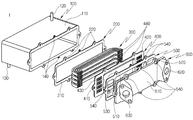
도 1은 본 발명에 의한 차량용 EGR 쿨러의 분해 사시도를 나타내고, 도 2는 본 발명의 일 실시예에서 플레이트에 튜브가 결합된 상태에서의 사시도를 나타낸다. 도 3은 본 발명의 일 실시예에서 플레이트에 튜브가 결합된 상태에서 일부가 절개된 상태의 측면 사시도를 나타내고, 도 4는 본 발명의 다른 일 실시예에서 플레이트에 튜브가 결합된 상태에서 일부가 절개된 상태의 측면 사시도를 나타낸다. 도 5는 본 발명의 제1 실시예에 의한 차량용 EGR 쿨러의 튜브의 단면도를 나타내고, 도 6은 본 발명의 제2 실시예에 의한 차량용 EGR 쿨러의 튜브의 단면도를 나타내며, 도 7은 본 발명의 제3 실시예에 의한 차량용 EGR 쿨러의 튜브의 단면도를 나타내고, 도 8은 본 발명의 제4 실시예에 의한 차량용 EGR 쿨러의 튜브의 단면도를 나타낸다.FIG. 1 is an exploded perspective view of a vehicle EGR cooler according to the present invention, and FIG. 2 is a perspective view showing a state where a tube is coupled to a plate in an embodiment of the present invention. FIG. 3 is a side perspective view showing a state in which a tube is partially cut in a state where a tube is coupled to a plate in an embodiment of the present invention, and FIG. 4 is a cross- And shows a side perspective view in an incised state. FIG. 5 is a sectional view of a tube of an EGR cooler for a vehicle according to a first embodiment of the present invention, FIG. 6 is a sectional view of a tube of an EGR cooler for a vehicle according to a second embodiment of the present invention, Sectional view of a tube of an EGR cooler for a vehicle according to a third embodiment, and Fig. 8 is a sectional view of a tube of an EGR cooler for a vehicle according to a fourth embodiment of the present invention.
이하에서 사용하는 용어의 정의는 다음과 같다. "길이방향"이란 하우징의 상부면의 일단에서 타단으로의 가로방향을 의미한다. "폭방향"이란 길이방향에 수직하도록 하우징의 상부면의 일측에서 타측으로 세로방향을 의미한다. "높이방향"이란 하우징의 측면의에서 일단에서 타단까지의 직선방향을 의미한다. "내측"이란 하우징의 내부를 향하는 방향을 의미한다. "외측"이란 하우징의 내부에서 외부로 향하는 방향을 의미한다.The definitions of terms used below are as follows. The term "longitudinal direction" means the lateral direction from one end to the other end of the upper surface of the housing. Means a longitudinal direction from one side of the upper surface of the housing to the other side so as to be perpendicular to the longitudinal direction. "Height direction" means a straight line direction from one end to the other end of the side surface of the housing. "Inner side" means a direction toward the inside of the housing. "Outside" means the direction from the inside to the outside of the housing.
도 1 내지 도 3 및 도 5를 참조하여 본 발명의 바람직한 일 실시예에 따른 차량용 EGR 쿨러(1)를 설명한다. 도 1 내지 도 3 및 도 5에 도시된 것처럼, 본 발명의 일 실시예에 따른 차량용 EGR 쿨러(1)는 하우징(100), 복수개의 튜브(300), 플레이트(400), 및 커버(600)를 포함한다.1 to 3 and 5, a
하우징(100)은 내부에 냉각유체인 냉각수를 수용한다. 반드시 이에 한정되는 것은 아니지만, 하우징(100)은 일측이 개구된 형태의 직육면체 형상으로 형성된다.The
도 1에 도시된 것처럼, 본 발명의 다른 일 실시예에 따르면, 하우징(100)은 본체부(110), 냉각수 유입구(120), 냉각수 유출구(130), 및 결합공(140)으로 이루어진다.As shown in FIG. 1, according to another embodiment of the present invention, the
본체부(110)는 하우징의 외형을 형성하고, 본체부(110)의 내부에 냉각수 유입구(120)를 통해 유입된 냉각수가 수용되는 공간이 형성된다. 이러한 본체부(110)는 엔진블록과 별개로 형성되어 엔진의 흡기매니폴드와 배기매니폴드 사이에 설치될 수 있다.The
냉각수 유입구(120)는 본체부(110)의 일부에 형성된다. 냉각수 유입구(120)를 통해 본체부(110)의 내부로 냉각수가 유입된다.The cooling
냉각수 유출구(130)는 본체부(110)의 일부에 형성된다. 냉각수 유출구를 통해 본체부(110)의 외부로 냉각수가 유출된다.The cooling
도 1에서 냉각수 유입구(120)와 냉각수 유출구(130)가 본체부(110)의 다른 면에 형성된 것으로 도시되어 있으나, 반드시 이에 한정되는 것은 아니다. 즉, 필요에 따라 냉각수 유입구(120)와 냉각수 유출구(130)가 본체부(110)의 동일면에 형성될 수도 있다.1, the cooling
결합공(140)이 본체부(110)의 외주면에 형성되어 후술하는 가스켓, 플레이트, 실링부재, 및 커버를 하우징에 볼트 체결을 통해 체결시킨다. 반드시 이에 한정되는 것은 아니지만, 결합공(140)은 상술한 가스켓, 플레이트, 실링부재, 및 커버를 하우징에 견고하게 체결하기 위해 본체부(110)의 외주면에 2개 이상 형성되는 것이 바람직하다.A
또한, 하우징(100)은 필요에 따라 엔진블록의 일부에 엔진블록과 일체로 형성될 수 있다. 즉, 하우징(100)의 외형을 형성하도록 일측이 개방된 형태의 본체부(110)가 엔진블록의 일부에 일체로 형성된다. 이에 따라, 본체부(110)에 냉각수 유입구(120)와 냉각수 유출구(130)를 별도로 형성하지 않아도 됨에 따라 조립공정 감소에 의해 EGR 쿨러 하우징의 제조시간 및 제조비용을 절감하고, EGR 쿨러가 차량의 엔진룸에 설치되는 공간을 최소화할 수 있다. Further, the
복수개의 튜브(300)가 하우징(100)의 내부에 삽입 설치된다. 즉, 복수개의 튜브(300)가 하우징(100)의 본체부(110)의 내부에 삽입 설치된다. 복수개의 튜브(300)는 각각 EGR 쿨러에서 배기가스가 유동되는 유로를 형성하게 된다. 즉, 복수개의 튜브(300)를 통해 배기가스가 유동되고, 이때에 하우징(100)의 본체부(110)의 내부에 있는 냉각수와 열교환을 통해 복수개의 튜브(300)를 지나면서 배기가스가 냉각되게 된다.A plurality of tubes (300) are inserted into the housing (100). That is, a plurality of
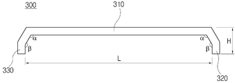
도 1 내지 도 3 및 도 5 에 도시된 것처럼, 본 발명의 일 실시예에 따른 차량용 EGR 쿨러(1)의 복수개의 튜브(300)는 각각 직선부(310), 제1 절곡부(320), 및 제2 절곡부(330)로 이루어진다.1 to 3 and 5, a plurality of
직선부(310)는 하우징(100)의 길이방향을 따라 수평하게 연장 형성된다.The
제1 절곡부(320)는 직선부(310)의 일단에서 절곡되어 형성된다. The first
제2 절곡부(330)는 제1 절곡부(320)와 마주하면서 제1 절곡부(320)와 동일한 길이를 갖도록 직선부(310)의 타단에서 절곡되어 형성된다. 즉, 제2 절곡부(330)의 높이(H)와 제1 절곡부(320)의 높이(H)가 동일하게 형성된다.The second
제1 절곡부(320)로 유입되어 직선부(310)를 통과한 후에 제2 절곡부(330)를 통해 하우징(100)의 외부로 배기가스가 유출될 때까지 튜브의 내부를 유동하는 배기가스는 하우징의 내부에 수용되는 냉각유체와 열교환을 하게 된다. The exhaust gas flows into the first
도 1 내지 도 8에서 제1 절곡부(320)는 배기가스가 유입되는 통로를 형성하고, 제2 절곡부(330)는 배기가스가 유출되는 통로를 형성한다. 그러나, 반드시 이에 한정되는 것은 아니며 반대로 제1 절곡부(320)가 배기가스가 유입되는 통도를 형성할 수 있고, 이때에는 제2 절곡부(330)가 배기가스가 유입되는 통로를 형성하게 된다.1 to 8, the first
직선부(310)의 길이(L)는 제1 절곡부(320)와 제2 절곡부(330)의 높이(H) 보다 길게 형성된다. The length L of the
이처럼, 직선부(310)의 길이(L)가 제1 절곡부(320) 및 제2 절곡부(330)의 높이(H)보다 길게 형성됨에 따라 배기가스가 냉각유체와 열교환되는 면적을 증가시킴에 따라 EGR 쿨러의 냉각성능을 개선하고, 배기가스 유입구와 유출구에서의 배기가스의 압력차를 개선할 수 있다.Since the length L of the
도 5 에 도시된 것처럼, 본 발명의 제1 실시예에 따르면 튜브(300)의 직선부(310)의 길이(L)는 제1 절곡부(320) 및 제2 절곡부(330)의 높이(H)의 1배 초과 20배 미만이 되도록 형성된다. 즉, 직선부(310)의 길이(L) 대 제1 절곡부(320) 및 제2 절곡부(330)의 높이(H)의 비는 20~1 대 1이 되도록 형성된다.(L:H = 20~1:1) 직선부(310)의 길이(L)가 제1 절곡부(320) 및 제2 절곡부9330)의 높이(H)의 1배 이하인 경우에는, 제1 절곡부(320)로 유입되는 배기가스의 압력과 제2 절곡부(330)로 배출되는 배기가스의 압력 차가 커지게 되어, 냉각효율이 저감되는 문제점이 발생한다. 또한, 직선부(310)의 길이(L)가 제1 절곡부(320) 및 제2 절곡부9330)의 높이(H)의 20배를 초과하는 경우에는, 하우징(100)을 포함한 EGR 쿨러의 크기가 너무 커져서 엔진블록에 일체로 형성될 수 없고, 별도로 하우징(100)을 형성하는 경우에도 엔진룸에 설치되는 공간상의 제약이 발생하여 EGR 쿨러의 소형화를 도모할 수 없는 문제점이 발생한다.5, according to the first embodiment of the present invention, the length L of the
도 5에 도시된 것처럼, 본 발명의 제1 실시예에 따르면, 튜브(300)의 제1 절곡부(320)는 직선부(310)의 일단에서 직선부(310)에 대해 수직하게 절곡 형성되고, 제2 절곡부(330)는 제1 절곡부(32)와 평행하도록 직선부(310)의 타단에서 직선부(310)에 대해 수직하게 절곡 형성된다. 제1 절곡부(320)와 제2 절곡부(330)가 직선부(310)의 일단과 타단에서 직선부(310)에 대해 90도를 이루도록 수직하게 절곡 형성됨에 따라 배기가스 유입구와 배기가스 유출구에서의 압력차가 감소하여 EGR 쿨러의 냉각성능 및 엔진효율을 향상시키고, 플레이트(400)의 유입공(420)과 유출공(430)에 제1 절곡부(320)와 제2 절곡부(330)를 용이하게 결합시킬 수 있다.5, according to the first embodiment of the present invention, the first
도 6에 도시된 것처럼, 본 발명의 제2 실시예에 따르면, 제1 절곡부(320)는 직선부(310)의 일단에서 직선부(310)와 둔각(α)을 이루도록 절곡되게 형성되고, 제2 절곡부(330)는 제1 절곡부(320)와 마주하도록 직선부(310)의 타단에서 직선부(310)와 둔각(α)을 이루도록 절곡되게 형성된다. 즉, 제1 절곡부(320)와 제2 절곡부(320)가 직선부(310)와 90도 보다 크고 180도 보다 작은 둔각(α)을 이루도록 형성됨에 따라 튜브(300)의 내부에서 유동하는 배기가스의 유동을 원활하게 하여 배기가스의 순환을 증가시킴에 따라 EGR 쿨러의 냉각효율을 향상시킬 수 있다.6, the first
도 7에 도시된 것처럼, 본 발명의 제3 실시예에 따르면, 제1 절곡부(320)는 둔각(β)을 이루도록 제1 절곡부(320)의 일부가 벤딩(bending)되도록 형성되고, 제2 절곡부(330)는 제1 절곡부(320)와 마주하면서 둔각(β)을 이루도록 제2 절곡부(330)의 일부가 벤딩되게 형성된다. 제1 절곡부(320)와 제2 절곡부(330)가 제1 절곡부(320)의 일부 및 제2 절곡부(330)의 일부에서 벤딩되게 형성됨에 따라, 튜브(300)의 내부에서 유동하는 배기가스의 유동을 원활하게 하여 배기가스의 순환을 증가시킴에 따라 EGR 쿨러의 냉각효율을 향상시키고, 플레이트(400)의 유입공(420)과 유출공(430)에 제1 절곡부(320)와 제2 절곡부(330)를 쉽게 결합시켜 EGR 쿨러의 조립시간 및 조립비용을 절감할 수 있다.7, according to the third embodiment of the present invention, the first
도 8에 도시된 것처럼, 본 발명의 제4 실시예에 따르면, 제1 절곡부(320)는 직선부(310)의 일단에서 직선부(310)에 소정의 곡률(R)을 갖도록 라운딩되게 절곡 형성되고, 제2 절곡부(320)는 제1 절곡부(320)와 마주하도록 직선부(310)의 타단에서 직선부(310)에 소정의 곡률(R)을 갖도록 라운딩되게 절곡 형성된다. 제1 절곡부(320)와 제2 절곡부(330)가 직선부(310)의 일단과 타단에서 소정의 곡률(R)을 갖도록 라운딩되게 절곡 형성됨에 따라, 제1 절곡부(320)로 유입되는 배기가스가 라운딩면을 따라 원활하게 직선부(310)로 이동하고, 직선부(310)를 딸 유동하는 배기가스가 제2 절곡부(330)의 라운딩 면을 따라 외부로 배출됨에 따라 배기가스의 유동을 최대한 원활하게 유도하여 배기가스의 순환속도를 증가시켜 EGR 쿨러의 냉각효율을 증대시킬 수 있다.8, the first
도 8 에 도시된 것처럼, 본 발명의 제4 실시예에 따르면, 제1 절곡부(320)와 제2 절곡부(330)가 직선부(310)의 일단과 타단에서 이루는 곡률(R)은 8mm 초과 30mm 미만이 되도록 형성되는 것이 바람직하다.(8mm<R<30mm) 곡률(R)이 8mm 이하인 경우에는 튜브의 제조성을 확보하기 어려운 문제점이 발생한다. 또한, 곡률(R)이 30mm를 초과하는 경우에는, 튜브(300)의 전체적인 크기가 커지고 이에 따라 하우징을 포함한 EGR 쿨러의 전체적인 사이즈가 커짐에 따라 엔진블록 또는 엔진룸에 별개로 설치되는 EGR 쿨러의 설치위치를 확보하기 어려운 문제점이 발생한다.8, according to the fourth embodiment of the present invention, the curvature R formed by the first
반드시 이에 한정되는 것은 아니지만, 각각의 튜브(300)의 직선부(310), 제1 절곡부(320), 및 제2 절곡부(330)는 금속재질로 일체로 형성될 수 있다.The
도 1 내지 도 3에 도시된 것처럼, 본 발명의 일 실시예에 따르면, 복수개의 튜브(300)는 하우징(100)의 내부에서 하우징(100)의 높이방향을 따라 소정 간격 이격되도록 다단으로 설치된다.As shown in FIGS. 1 to 3, according to an embodiment of the present invention, a plurality of
또한, 동일한 단에 설치되는 복수개의 튜브(300)는 하우징(100)의 내부에서 하우징(100)의 폭방향을 따라 소정 간격 이격되도록 다열로 설치된다. 이처럼, 복수개의 튜브가 하우징(100)의 내부에서 하우징(100)의 높이방향 및 하우징(100)의 폭방향을 따라 다단 다열로 배열됨에 따라, 하우징(100)의 본체부(110) 내부를 지나가는 배기가스와 냉각유체가 접촉하는 면적을 증가시켜 열교환량을 증대시킬 수 있다.The plurality of
도 1 내지 도 3에 도시된 것처럼, 본 발명의 일 실시예에 따르면, 각각의 튜브(300)의 직선부(310) 및 제1 절곡부(320)와 제2 절곡부(330)의 외측면 또는 내측면에 복수개의 오목부(311)가 형성될 수 있다. 도 1 내지 도 3에서는 폭방향에 대해 대각선 방향으로 복수개의 오목부(311)가 형성된 것이 도시되어 있으나, 반드시 이에 한정되는 것은 아니면, 오목부(311)의 형상 및 방향은 필요에 따라 다양한 형태로 형성될 수 있다.1 to 3, according to an embodiment of the present invention, the
도 4에 도시된 것처럼, 본 발명의 다른 일 실시예에 따르면, 복수개의 튜브(300)는 하우징(100)의 내부에서 하우징(100)의 높이방향을 따라 소정 간격 이격되도록 다단으로 형성된다. 또한, 동일한 단에 설치되는 튜브(300)는 하우징(100)의 내부에서 하우징(100)의 폭방향을 따라 연장 형성되는 단일의 튜브로 형성될 수 있다. 이처럼, 복수개의 튜브가 하우징(100)의 내부에서 하우징(100)의 높이방향 을 따라 다단으로 형성되고, 동일단에서 단일의 튜브(300)가 하우징(100)의 폭방향을 따라 연장 형성됨에 따라, 하우징(100)의 본체부(110) 내부를 지나가는 배기가스와 냉각유체가 접촉하는 면적을 증가시켜 열교환량을 증대시킬 수 있다.As shown in FIG. 4, according to another embodiment of the present invention, the plurality of
도 4에 도시된 것처럼, 본 발명의 다른 일 실시예에 따르면, 각각의 튜브(300)의 직선부(310)의 내부 또는 제1 절곡부(320)와 제2 절곡부(330)의 내부에 방열핀(340)이 삽입 설치될 수 있다. 이처럼, 직선부(310)의 내부 또는 제1 절곡부(320)와 제2 절곡부(330)의 내부에 방열핀(340)이 삽입 설치됨에 따라 하우징(100)의 본체부(110) 내부를 지나가는 배기가스와 냉각유체가 접촉하는 면적을 증가시켜 열교환량을 증대시킬 수 있다.According to another embodiment of the present invention, as shown in FIG. 4, the inside of the
플레이트(400)는 복수개의 튜브(300)를 고정 지지하는 기능을 수행한다.The
도 1에 도시된 것처럼, 본 발명의 다른 일 실시예에 따르면, 플레이트(400)는 바디부(410), 복수개의 유입공(420), 복수개의 유출공(430), 및 삽입공(440)으로 이루어진다.1, according to another embodiment of the present invention, the
바디부(410)는 대략 직사각형의 판 형상으로 형성되어 플레이트(400)의 외형을 형성한다.The
복수개의 유입공(420)이 각각의 제1 절곡부(320)와 연통되도록 바디부(410)의 일부에 관통 형성된다. 각각의 유입공(420)의 형상은 제1 절곡부(320)의 단면 형상과 동일한 형상을 갖도록 형성된다. 이에 따라, 복수개의 제1 절곡부(320)를 복수개의 유입공(420)에 용이하게 삽입 체결할 수 있다. A plurality of
복수개의 유출공(430)이 각각의 제2 절곡부(320)와 연통되도록 바디부(420)의 일부에 형성된다. 즉, 복수개의 유출공(430)은 바디부(420) 상에서 복수개의 유입공(420)과 마주하도록 제2 절곡부(320)와 대응되는 위치에 형성된다. 각각의 유출공(430)의 형상은 제2 절곡부(330)의 단면 형상과 동일한 형상을 갖도록 형성된다. 이에 따라, 복수개의 제2 절곡부(330)를복수개의 유출공(430)에 용이하게 삽입 체결할 수 있다.A plurality of
삽입공(440)이 바디부(410)의 둘레면에 결합공(140)과 대응하도록 형성된다. 즉, 삽입공(440)은 결합공(140)의 개수 및 결합공(140)의 위치와 대응하도록 바디부(410)의 둘레면에 형성된다.The
커버(600)는 플레이트(400)의 외측에 설치되어 하우징(100)을 폐쇄한다.The
도 1에 도시된 것처럼, 본 발명의 다른 일 실시예에 따르면, 커버(600)는 베이스부(610), 배기가스 유입구(620), 배기가스 유출구(630), 및 체결공(640)으로 이루어진다.1, according to another embodiment of the present invention, the
베이스부(610)는 대략 직사각형의 판 형상으로 형성되어 커버(600)의 외형을 형성한다.The
배기가스 유입구(620)가 유입공(420)과 연통되도록 베이스부(610)의 일부에 관통 형성된다. 도면에 도시되지는 않았지만, 배기가스 유입구(620)에는 배기가스 유로가 연결되고, 배기가스 유로의 타단은 배기매니폴드와 연통된다.An
배기가스 유출구(630)가 유출공(430)과 연통되도록 베이스부(610)의 일부에 형성된다. 즉, 배기가스 유출구(630)는 베이스부(610) 상에서 배기가스 유입구(620)와 마주하도록 배기가스 유입구(320)와 대응되는 위치에 형성된다. 도 1에서 배기가스 유입구(620)가 베이스부(610)의 좌측에 배기가스 유출구(620)가 베이스부(610)의 우측에 형성되는 것으로 도시되어 있으나, 반드시 이에 한정되는 것은 아니며 필요에 따라 반대로 형성될 수 있다. 즉, 배기가스 유입구(620)가 베이스부(610)의 우측에 형성되는 경우에는 상술한 제1 절곡부(320), 유입공(420)의 위치도 모두 우측에 형성된다. 도면에 도시되지는 않았지만, 배기가스 유출구(630)에는 배기가스 유로가 연결되고, 배기가스 유로의 타단은 흡기매니폴드와 연통된다.And an
체결공(640)이 베이스부(610)의 둘레면에 삽입공(440)과 대응하도록 형성된다. 즉, 체결공(640)은 삽입공(440)의 개수 및 결합공(440)의 위치와 대응하도록 베이스부(610)의 둘레면에 형성된다.A
결합공(640), 삽입공(440), 및 체결공(640)이 동일한 개수와 동일한 위치에 형성됨에 따라, 플레이트(400)와 커버(600)를 하우징(100)에 결합할 때에 볼트체결을 통해 쉽게 결합할 수 있다. 따라서, EGR 쿨러의 조립시간 및 조립비용을 단축할 수 있다.The
도 1에 도시된 것처럼, 본 발명의 다른 일 실시예에 따른 차량용 EGR 쿨러(1)는 가스켓(200) 또는 실링부재(500)를 더 포함할 수 있다.As shown in FIG. 1, the
가스켓(200)은 하우징(100)과 플레이트(400) 사이에 설치되어 1차적으로 하우징(100)의 본체부(110)에서 냉각유체가 하우징(100)의 외부로 누출되는 것을 방지한다.The
본 발명의 일 실시예에 따르면, 가스켓(200)은 몸체부(210)와 관통공(220)으로 이루어진다.According to an embodiment of the present invention, the
몸체부(210)는 중앙에 공동을 구비하고, 대략 직사각형의 판 형상으로 형성되어 가스켓(200)의 외형을 형성한다.The
관통공(220)이 몸체부(210)의 둘레면에 결합공(140)과 대응하도록 관통 형성된다. 즉, 관통공(220)은 상술한 결합공(140), 삽입공(440), 및 체결공(640)의 개수 및 위치와 대응하도록 몸체부(210)의 둘레면에 형성된다. 이에 따라, 가스켓(200)을 각각의 결합공(140), 삽입공(440), 체결공(640), 및 관통공(220)에 삽입되는 볼트에 의해 하우징(100)에 용이하게 결합시킬 수 있다.The through
실링부재(500)는 플레이트(400)와 커버(600) 사이에 설치되어 2차적으로 하우징(100)의 본체부(110)에서 냉각유체가 하우징(100)의 외부로 누출되는 것을 방지한다.The sealing
본 발명의 일 실시예에 따르면, 실링부재(500)는 몸통부(510), 제1 구획부(520), 제2 구획부(530), 및 연결공(540)으로 이루어진다.According to an embodiment of the present invention, the sealing
몸통부(510)는 대략 직사각형의 판 형상으로 형성되어 실링부재(500)의 외형을 형성한다.The
제1 구획부(520)는 몸통부(510)의 일부에 하우징(100)의 폭방향을 따라 형성되어 유입공(420)과 배기가스 유입구(620)에서 배기가스가 외부로 유출되지 않도록 플레이트와 커버 사이의 내부공간을 구획한다.The
제2 구획부(530)는 몸통부(510)의 일부에 하우징(100)의 폭방향을 따라 형성되어 유출공(430)과 배기가스 유출구(630)에서 배기가스가 외부로 유출되지 않도록 플레이트와 커버 사이의 내부공간을 구획한다. 즉, 제2 구획부(530)는 제1 구획부(520)와 마주하도록 실링부재(500)의 몸통부(510)의 타측에 형성된다.The
연결공(540)이 몸통부(510)의 둘레면에 삽입공(440)과 대응하도록 관통 형성된다. 즉, 연결공(540)은 상술한 결합공(140), 관통공(220), 삽입공(440), 및 체결공(640)의 개수 및 위치와 대응하도록 몸통부(510)의 둘레면에 형성된다. 이에 따라, 실링부재(500)를 각각의 결합공(140), 관통공(220), 삽입공(440), 체결공(640), 및 연결공(524)에 삽입되는 볼트에 의해 하우징(100)에 용이하게 결합시킬 수 있다.The
본 발명은 도면에 도시된 변형예와 상기에서 설명된 실시예에 국한되지 않으며, 첨부된 청구항의 범주내에 속하는 다른 실시예로 확장될 수 있다.The present invention is not limited to the modifications shown in the drawings and the embodiments described above, but may be extended to other embodiments falling within the scope of the appended claims.
1 : EGR 쿨러
100 : 하우징
110 : 본체
120 : 냉각수 유입구
130 : 냉각수 유출구
140 : 결합공
200 : 가스켓
210 : 몸체부
220 : 관통공
300 : 튜브
310 : 직선부
311 : 오목부
320 : 제1 절곡부
330 : 제2 절곡부
340 : 방열핀
400 : 플레이트
410 : 바디부
420 : 유입공
430 : 유출공
440 : 삽입공
500 : 실링부재
510 : 몸통부
520 : 제1 구획부
530 : 제2 구획부
540 : 연결공
600 : 커버
610 : 베이스부
620 : 배기가스 유입구
630 : 배기가스 유출구
640 : 체결공1: EGR cooler 100: housing
110: main body 120: cooling water inlet
130: cooling water outlet 140: coupling hole
200: gasket 210:
220: through hole 300: tube
310: straight portion 311: concave portion
320: first bent portion 330: second bent portion
340: radiating fin 400: plate
410: Body part 420: Inlet ball
430: Outflow hole 440: Insertion hole
500: sealing member 510: body portion
520: first partitioning part 530: second partitioning part
540: connecting ball 600: cover
610: Base portion 620: Exhaust gas inlet
630: exhaust gas outlet 640: fastening hole
Claims (17)
상기 하우징(100)의 내부에 삽입 설치되어, 배기가스 유로를 형성하는 복수개의 튜브(300);
복수개의 상기 튜브(300)를 고정하기 위한 플레이트(400); 및
상기 플레이트(400)의 외측에 설치되는 커버(600);를 포함하고,
복수개의 상기 튜브(300)는 각각,
상기 하우징(100)의 길이방향을 따라 수평하게 연장 형성되는 직선부(310);
상기 직선부(310)의 일단에서 절곡 형성되는 제1 절곡부(320); 및
상기 제1 절곡부(320)와 마주하도록 상기 직선부(310)의 타단에서 절곡 형성되는 제2 절곡부(330);를 포함하되,
상기 직선부(310)의 길이(L)가 상기 제1 절곡부(320)와 상기 제2 절곡부(330)의 높이(H) 보다 길게 형성되는 것을 특징으로 하는 차량용 EGR 쿨러.
A housing (100) for accommodating a cooling fluid therein;
A plurality of tubes (300) inserted in the housing (100) and forming an exhaust gas flow path;
A plate (400) for fixing the plurality of tubes (300); And
And a cover 600 installed on the outer side of the plate 400,
The plurality of tubes (300)
A straight line 310 extending horizontally along the longitudinal direction of the housing 100;
A first bent part 320 bent at one end of the rectilinear part 310; And
And a second bent part 330 bent at the other end of the straight line part 310 so as to face the first bent part 320,
Wherein a length L of the rectilinear section 310 is longer than a height H of the first bend section 320 and the second bend section 330.
상기 직선부(310)의 길이(L)는 상기 제1 절곡부(320) 및 상기 제2 절곡부(330)의 높이(H)의 1배 초과 20배 이하의 길이가 되도록 형성되는 것을 특징으로 하는 차량용 EGR 쿨러.The method according to claim 1,
The length L of the rectilinear section 310 may be greater than or equal to 1 to 20 times the height H of the first bend section 320 and the second bend section 330 EGR cooler for vehicles.
상기 제1 절곡부(320)는 상기 직선부(310)의 일단에서 상기 직선부(310)에 대해 수직하게 절곡 형성되고,
상기 제2 절곡부(330)는 상기 제1 절곡부(32)와 평행하도록 상기 직선부(310)의 타단에서 상기 직선부(310)에 대해 수직하게 절곡 형성되는 것을 특징으로 하는 차량용 EGR 쿨러.
3. The method of claim 2,
The first bent portion 320 is bent at one end of the rectilinear section 310 so as to be perpendicular to the rectilinear section 310,
Wherein the second bend part (330) is formed to be perpendicular to the straight part (310) at the other end of the straight part (310) so as to be parallel to the first bend part (32).
상기 제1 절곡부(320)는 상기 직선부(310)의 일단에서 상기 직선부(310)와 둔각(α)을 이루도록 절곡 형성되고,
상기 제2 절곡부(330)는 상기 제1 절곡부(320)와 마주하도록 상기 직선부(310)의 타단에서 상기 직선부(310)와 둔각(α)을 이루도록 절곡 형성되는 것을 특징으로 하는 차량용 EGR 쿨러.
3. The method of claim 2,
The first bent portion 320 is bent at one end of the rectilinear section 310 so as to form an obtuse angle alpha with the rectilinear section 310,
Wherein the second bent portion 330 is bent at an obtuse angle alpha with the straight portion 310 at the other end of the straight portion 310 so as to face the first bent portion 320. [ EGR cooler.
상기 제1 절곡부(320)는 둔각(β)을 이루도록 상기 제1 절곡부(320)의 일부가 벤딩되게 형성되고,
상기 제2 절곡부(330)는 상기 제1 절곡부(320)와 마주하면서 둔각(β)을 이루도록 상기 제2 절곡부(330)의 일부가 벤딩되게 형성되는 것을 특징으로 하는 차량용 EGR 쿨러.
5. The method of claim 4,
The first bent portion 320 is formed to bend a part of the first bent portion 320 so as to form an obtuse angle β,
Wherein the second bend part (330) is formed to bend a part of the second bend part (330) so as to form an obtuse angle (beta) while facing the first bend part (320).
상기 제1 절곡부(320)는 상기 직선부(310)의 일단에서 상기 직선부(310)에 소정의 곡률(R)을 갖도록 라운딩되게 절곡 형성되고,
상기 제2 절곡부(320)는 상기 제1 절곡부(320)와 마주하도록 상기 직선부(310)의 타단에서 상기 직선부(310)에 소정의 곡률(R)을 갖도록 라운딩되게 절곡 형성되는 것을 특징으로 하는 차량용 EGR 쿨러. 3. The method of claim 2,
The first bent portion 320 is bent at one end of the rectilinear portion 310 so as to have a predetermined curvature R at the rectilinear portion 310,
The second bent portion 320 is bent so as to have a predetermined curvature R at the linear portion 310 at the other end of the linear portion 310 so as to face the first bent portion 320 Features EGR cooler for vehicles.
상기 곡률(R)은 8mm 초과 30mm 미만인 것을 특징으로 하는 차량용 EGR 쿨러.
The method according to claim 6,
Wherein the curvature (R) is greater than 8 mm but less than 30 mm.
각각의 상기 튜브(300)의 상기 직선부(310), 상기 제1 절곡부(320), 및 상기 제2 절곡부(330)는 일체로 형성되는 것을 특징으로 하는 차량용 EGR 쿨러.8. The method according to any one of claims 1 to 7,
Wherein the straight portion (310), the first bent portion (320), and the second bent portion (330) of each tube (300) are integrally formed.
복수개의 상기 튜브(300)는 상기 하우징(100)의 내부에서 상기 하우징(100)의 높이방향을 따라 소정 간격 이격되도록 다단으로 설치되고,
동일한 단에 설치되는 복수개의 튜브(300)는 상기 하우징(100)의 내부에서 상기 하우징(100)의 폭방향을 따라 소정 간격 이격되도록 다열로 설치되는 것을 특징으로 하는 차량용 EGR 쿨러.
3. The method of claim 2,
The plurality of tubes 300 are installed in the housing 100 in a plurality of stages at predetermined intervals along the height direction of the housing 100,
Wherein a plurality of tubes (300) installed at the same end are installed in multiple rows in the housing (100) so as to be spaced apart from each other by a predetermined distance along the width direction of the housing (100).
각각의 상기 튜브(300)의 상기 직선부(310) 및 상기 제1 절곡부(320)와 제2 절곡부(330)의 외측면 또는 내측면에 오목부(311)가 형성되는 것을 특징으로 하는 차량용 EGR 쿨러.
10. The method of claim 9,
And the concave portion 311 is formed on the outer surface or the inner surface of the rectilinear portion 310 and the first bent portion 320 and the second bent portion 330 of each of the tubes 300. [ EGR cooler for vehicles.
복수개의 상기 튜브(300)는 상기 하우징(100)의 내부에서 상기 하우징(100)의 높이방향을 따라 소정 간격 이격되도록 다단으로 설치되고,
동일한 단에 설치되는 튜브(300)는 상기 하우징(100)의 내부에서 상기 하우징(100)의 폭방향을 따라 연장 형성되는 단일의 튜브(300)로 형성되는 것을 특징으로 하는 차량용 EGR 쿨러.
3. The method of claim 2,
The plurality of tubes 300 are installed in the housing 100 in a plurality of stages at predetermined intervals along the height direction of the housing 100,
Wherein the tube (300) installed at the same end is formed by a single tube (300) extending in the width direction of the housing (100) inside the housing (100).
상기 튜브(300)의 상기 직선부(310)의 내부 또는 상기 제1 절곡부(320)와 상기 제2 절곡부(330)의 내부에 방열핀(340)이 삽입 설치되는 것을 특징으로 하는 차량용 EGR 쿨러.
11. The method of claim 10,
Wherein a radiating fin (340) is inserted into the linear portion (310) of the tube (300) or inside the first bent portion (320) and the second bent portion (330) .
상기 하우징(100)은,
본체부(110);
상기 본체부(110)의 일부에 형성되어, 상기 본체부(110)의 내부로 냉각유체가 유입되는 냉각수 유입구(120);
상기 본체부(110)의 일부에 형성되어, 상기 본체부(110)의 외부로 냉각유체가 유출되는 냉각수 유출구(130); 및
상기 본체부(110)의 외주면에 형성되는 결합공(140);을 포함하는 것을 특징으로 하는 차량용 EGR 쿨러.
13. The method of claim 12,
The housing (100)
A main body 110;
A cooling water inlet 120 formed in a part of the main body 110 and through which the cooling fluid flows into the main body 110;
A cooling water outlet 130 formed in a part of the main body 110 and through which the cooling fluid flows out of the main body 110; And
And an engaging hole (140) formed on the outer circumferential surface of the main body part (110).
상기 플레이트(400)는,
바디부(410);
각각의 상기 제1 절곡부(320)와 연통되도록, 상기 바디부(410)의 일부에 형성되는 복수개의 유입공(420);
각각의 상기 제2 절곡부(320)와 연통되도록, 상기 바디부(420)의 일부에 형성되는 복수개의 유출공(430); 및
상기 바디부(410)의 둘레면에 상기 결합공(140)과 대응하도록 형성되는 삽입공(440);을 포함하는 것을 특징으로 하는 차량용 EGR 쿨러.
14. The method of claim 13,
The plate (400)
A body portion 410;
A plurality of inflow holes 420 formed in a part of the body 410 to communicate with the respective first bent portions 320;
A plurality of outflow holes 430 formed in a part of the body 420 to communicate with the respective second bent portions 320; And
And an insertion hole (440) formed in the circumferential surface of the body part (410) so as to correspond to the engagement hole (140).
상기 커버(600)는,
베이스부(610);
상기 유입공(420)과 연통되도록, 상기 베이스부(610)의 일부에 형성되는 배기가스 유입구(620);
상기 유출공(430)과 연통되도록, 상기 베이스부(610)의 일부에 형성되는 배기가스 유출구(630); 및
상기 베이스부(610)의 둘레면에 상기 삽입공(440)과 대응하도록 형성되는 체결공(640);을 포함하는 것을 특징으로 하는 차량용 EGR 쿨러.15. The method of claim 14,
The cover (600)
A base portion 610;
An exhaust gas inlet 620 formed in a portion of the base portion 610 to communicate with the inlet hole 420;
An exhaust gas outlet 630 formed in a part of the base 610 to communicate with the outflow hole 430; And
And a fastening hole (640) formed on the circumferential surface of the base part (610) so as to correspond to the insertion hole (440).
상기 하우징(100)과 상기 플레이트(400) 사이에 설치되는 가스켓(200);을 더 포함하되,
상기 가스켓(200)은,
몸체부(210); 및
상기 몸체부(210)의 둘레면에 상기 결합공(140)과 대응하도록 형성되는 관통공(220);을 포함하는 것을 특징으로 하는 차량용 EGR 쿨러.
16. The method of claim 15,
And a gasket (200) installed between the housing (100) and the plate (400)
The gasket (200)
A body portion 210; And
And a through hole (220) formed in the circumferential surface of the body portion (210) so as to correspond to the engaging hole (140).
상기 플레이트(400)와 상기 커버(600) 사이에 설치되는 실링부재(500);를 더 포함하되,
상기 실링부재(500)는,
몸통부(510);
상기 몸통부(510)의 일부에 상기 유입공(420)을 구획하기 위해 형성되는 제1 구획부(520);
상기 몸통부(510)의 일부에 상기 유출공(430)을 구획하기 위해 형성되는 제2 구획부(530); 및
상기 몸통부(510)의 둘레면에 상기 삽입공(440)과 대응하도록 형성되는 연결공(540);을 포함하는 것을 특징으로 하는 차량용 EGR 쿨러. 17. The method of claim 16,
And a sealing member (500) installed between the plate (400) and the cover (600)
The sealing member (500)
A body portion 510;
A first compartment 520 formed in a part of the body 510 to define the inflow hole 420;
A second compartment 530 formed in a part of the body 510 to define the outlet hole 430; And
And a connection hole (540) formed on the circumferential surface of the body portion (510) so as to correspond to the insertion hole (440).
Priority Applications (5)
| Application Number | Priority Date | Filing Date | Title |
|---|---|---|---|
| KR1020160046295A KR20170118469A (en) | 2016-04-15 | 2016-04-15 | EGR cooler for vehicle |
| CN201680028281.9A CN107614860B (en) | 2015-09-25 | 2016-08-10 | EGR cooler for vehicle |
| PCT/KR2016/008771 WO2017052071A1 (en) | 2015-09-25 | 2016-08-10 | Vehicular egr cooler |
| US15/544,997 US20170370329A1 (en) | 2015-09-25 | 2016-08-10 | Vehicular egr cooler |
| DE112016000323.4T DE112016000323T5 (en) | 2015-09-25 | 2016-08-10 | Exhaust gas recirculation cooler for a vehicle |
Applications Claiming Priority (1)
| Application Number | Priority Date | Filing Date | Title |
|---|---|---|---|
| KR1020160046295A KR20170118469A (en) | 2016-04-15 | 2016-04-15 | EGR cooler for vehicle |
Publications (1)
| Publication Number | Publication Date |
|---|---|
| KR20170118469A true KR20170118469A (en) | 2017-10-25 |
Family
ID=60300052
Family Applications (1)
| Application Number | Title | Priority Date | Filing Date |
|---|---|---|---|
| KR1020160046295A KR20170118469A (en) | 2015-09-25 | 2016-04-15 | EGR cooler for vehicle |
Country Status (1)
| Country | Link |
|---|---|
| KR (1) | KR20170118469A (en) |
Cited By (1)
| Publication number | Priority date | Publication date | Assignee | Title |
|---|---|---|---|---|
| WO2020045776A1 (en) * | 2018-08-27 | 2020-03-05 | 한온시스템 주식회사 | Heat exchanger of exhaust heat recovery apparatus |
-
2016
- 2016-04-15 KR KR1020160046295A patent/KR20170118469A/en not_active Application Discontinuation
Cited By (2)
| Publication number | Priority date | Publication date | Assignee | Title |
|---|---|---|---|---|
| WO2020045776A1 (en) * | 2018-08-27 | 2020-03-05 | 한온시스템 주식회사 | Heat exchanger of exhaust heat recovery apparatus |
| US11603782B2 (en) | 2018-08-27 | 2023-03-14 | Hanon Systems | Heat exchanger of exhaust heat recovery apparatus |
Similar Documents
| Publication | Publication Date | Title |
|---|---|---|
| US20170370329A1 (en) | Vehicular egr cooler | |
| US8596339B2 (en) | U-flow stacked plate heat exchanger | |
| ES2351477T3 (en) | HEAT EXCHANGER ARRANGEMENT. | |
| RU2718387C2 (en) | System (versions) and method for cooler of exhaust gas recirculation system | |
| US20070193732A1 (en) | Heat exchanger | |
| KR100814073B1 (en) | Plastic type egr cooler | |
| KR100814071B1 (en) | Egr cooler | |
| KR20150122803A (en) | Heat exchanger, in particular a supercharging air cooler | |
| ES2300163B1 (en) | SYSTEM FOR THE CONTROL OF GAS CIRCULATION, IN SPECIAL OF THE EXHAUST GASES OF A MOTOR. | |
| US11319905B2 (en) | EGR cooler and engine system having the same | |
| US11067040B2 (en) | Exhaust gas cooling apparatus | |
| KR20170048022A (en) | EGR cooler for vehicle | |
| US10533525B2 (en) | Heat exchanger for vehicle | |
| US10794337B2 (en) | EGR cooler | |
| CN110388844B (en) | System for connecting housing elements of a device for heat conduction | |
| KR20170118469A (en) | EGR cooler for vehicle | |
| CN110878728B (en) | Exhaust gas recirculation cooler | |
| KR102173402B1 (en) | EGR cooler for vehicle | |
| KR102173379B1 (en) | EGR cooler for vehicle | |
| US11448169B2 (en) | Vehicle exhaust gas recirculation cooler | |
| US20150021004A1 (en) | EGR Cooler | |
| JP2015025421A (en) | Egr cooling device | |
| KR102303621B1 (en) | EGR cooler for vehicle | |
| KR102173369B1 (en) | EGR cooler for vehicle | |
| JP2004502066A (en) | Exhaust volume and exhaust system including this exhaust volume |
Legal Events
| Date | Code | Title | Description |
|---|---|---|---|
| A201 | Request for examination | ||
| E902 | Notification of reason for refusal | ||
| E601 | Decision to refuse application |