KR20190132245A - Method of detecting a polishing surface of a polishing pad using a polishing head, and polishing apparatus - Google Patents
Method of detecting a polishing surface of a polishing pad using a polishing head, and polishing apparatus Download PDFInfo
- Publication number
- KR20190132245A KR20190132245A KR1020190056958A KR20190056958A KR20190132245A KR 20190132245 A KR20190132245 A KR 20190132245A KR 1020190056958 A KR1020190056958 A KR 1020190056958A KR 20190056958 A KR20190056958 A KR 20190056958A KR 20190132245 A KR20190132245 A KR 20190132245A
- Authority
- KR
- South Korea
- Prior art keywords
- polishing
- head
- polishing head
- pad
- distortion sensor
- Prior art date
Links
- 238000005498 polishing Methods 0.000 title claims abstract description 397
- 238000000034 method Methods 0.000 title claims abstract description 22
- 238000003825 pressing Methods 0.000 claims description 33
- 239000000758 substrate Substances 0.000 claims description 17
- 238000005452 bending Methods 0.000 claims description 10
- 238000003860 storage Methods 0.000 claims description 9
- 238000012545 processing Methods 0.000 claims description 7
- 230000008569 process Effects 0.000 claims description 3
- 235000012431 wafers Nutrition 0.000 description 53
- 239000007789 gas Substances 0.000 description 12
- 238000006073 displacement reaction Methods 0.000 description 11
- 239000007788 liquid Substances 0.000 description 10
- 230000006870 function Effects 0.000 description 9
- 239000012528 membrane Substances 0.000 description 9
- 239000012530 fluid Substances 0.000 description 8
- 230000007246 mechanism Effects 0.000 description 8
- 125000006850 spacer group Chemical group 0.000 description 6
- 238000006243 chemical reaction Methods 0.000 description 4
- 238000005096 rolling process Methods 0.000 description 4
- 239000002245 particle Substances 0.000 description 3
- 230000002093 peripheral effect Effects 0.000 description 3
- 239000004065 semiconductor Substances 0.000 description 3
- XLYOFNOQVPJJNP-UHFFFAOYSA-N water Substances O XLYOFNOQVPJJNP-UHFFFAOYSA-N 0.000 description 3
- 230000009471 action Effects 0.000 description 2
- 238000004891 communication Methods 0.000 description 2
- 238000010586 diagram Methods 0.000 description 2
- 230000003287 optical effect Effects 0.000 description 2
- 239000000126 substance Substances 0.000 description 2
- IJGRMHOSHXDMSA-UHFFFAOYSA-N Atomic nitrogen Chemical compound N#N IJGRMHOSHXDMSA-UHFFFAOYSA-N 0.000 description 1
- 229920000742 Cotton Polymers 0.000 description 1
- VYPSYNLAJGMNEJ-UHFFFAOYSA-N Silicium dioxide Chemical compound O=[Si]=O VYPSYNLAJGMNEJ-UHFFFAOYSA-N 0.000 description 1
- 238000004364 calculation method Methods 0.000 description 1
- 230000008859 change Effects 0.000 description 1
- 230000006835 compression Effects 0.000 description 1
- 238000007906 compression Methods 0.000 description 1
- 230000003750 conditioning effect Effects 0.000 description 1
- 229910003460 diamond Inorganic materials 0.000 description 1
- 239000010432 diamond Substances 0.000 description 1
- 229910001873 dinitrogen Inorganic materials 0.000 description 1
- 238000005516 engineering process Methods 0.000 description 1
- 238000012886 linear function Methods 0.000 description 1
- 238000004519 manufacturing process Methods 0.000 description 1
- 239000002184 metal Substances 0.000 description 1
- 238000012986 modification Methods 0.000 description 1
- 230000004048 modification Effects 0.000 description 1
- 238000012544 monitoring process Methods 0.000 description 1
- 238000007639 printing Methods 0.000 description 1
- 238000000611 regression analysis Methods 0.000 description 1
- 239000002002 slurry Substances 0.000 description 1
- 239000007787 solid Substances 0.000 description 1
Images


Classifications
-
- B—PERFORMING OPERATIONS; TRANSPORTING
- B24—GRINDING; POLISHING
- B24B—MACHINES, DEVICES, OR PROCESSES FOR GRINDING OR POLISHING; DRESSING OR CONDITIONING OF ABRADING SURFACES; FEEDING OF GRINDING, POLISHING, OR LAPPING AGENTS
- B24B37/00—Lapping machines or devices; Accessories
- B24B37/04—Lapping machines or devices; Accessories designed for working plane surfaces
- B24B37/07—Lapping machines or devices; Accessories designed for working plane surfaces characterised by the movement of the work or lapping tool
- B24B37/10—Lapping machines or devices; Accessories designed for working plane surfaces characterised by the movement of the work or lapping tool for single side lapping
-
- B—PERFORMING OPERATIONS; TRANSPORTING
- B24—GRINDING; POLISHING
- B24B—MACHINES, DEVICES, OR PROCESSES FOR GRINDING OR POLISHING; DRESSING OR CONDITIONING OF ABRADING SURFACES; FEEDING OF GRINDING, POLISHING, OR LAPPING AGENTS
- B24B49/00—Measuring or gauging equipment for controlling the feed movement of the grinding tool or work; Arrangements of indicating or measuring equipment, e.g. for indicating the start of the grinding operation
- B24B49/16—Measuring or gauging equipment for controlling the feed movement of the grinding tool or work; Arrangements of indicating or measuring equipment, e.g. for indicating the start of the grinding operation taking regard of the load
-
- B—PERFORMING OPERATIONS; TRANSPORTING
- B24—GRINDING; POLISHING
- B24B—MACHINES, DEVICES, OR PROCESSES FOR GRINDING OR POLISHING; DRESSING OR CONDITIONING OF ABRADING SURFACES; FEEDING OF GRINDING, POLISHING, OR LAPPING AGENTS
- B24B37/00—Lapping machines or devices; Accessories
- B24B37/005—Control means for lapping machines or devices
-
- B—PERFORMING OPERATIONS; TRANSPORTING
- B24—GRINDING; POLISHING
- B24B—MACHINES, DEVICES, OR PROCESSES FOR GRINDING OR POLISHING; DRESSING OR CONDITIONING OF ABRADING SURFACES; FEEDING OF GRINDING, POLISHING, OR LAPPING AGENTS
- B24B37/00—Lapping machines or devices; Accessories
- B24B37/11—Lapping tools
- B24B37/20—Lapping pads for working plane surfaces
-
- B—PERFORMING OPERATIONS; TRANSPORTING
- B24—GRINDING; POLISHING
- B24B—MACHINES, DEVICES, OR PROCESSES FOR GRINDING OR POLISHING; DRESSING OR CONDITIONING OF ABRADING SURFACES; FEEDING OF GRINDING, POLISHING, OR LAPPING AGENTS
- B24B37/00—Lapping machines or devices; Accessories
- B24B37/27—Work carriers
- B24B37/30—Work carriers for single side lapping of plane surfaces
-
- B—PERFORMING OPERATIONS; TRANSPORTING
- B24—GRINDING; POLISHING
- B24B—MACHINES, DEVICES, OR PROCESSES FOR GRINDING OR POLISHING; DRESSING OR CONDITIONING OF ABRADING SURFACES; FEEDING OF GRINDING, POLISHING, OR LAPPING AGENTS
- B24B37/00—Lapping machines or devices; Accessories
- B24B37/34—Accessories
-
- B—PERFORMING OPERATIONS; TRANSPORTING
- B24—GRINDING; POLISHING
- B24B—MACHINES, DEVICES, OR PROCESSES FOR GRINDING OR POLISHING; DRESSING OR CONDITIONING OF ABRADING SURFACES; FEEDING OF GRINDING, POLISHING, OR LAPPING AGENTS
- B24B49/00—Measuring or gauging equipment for controlling the feed movement of the grinding tool or work; Arrangements of indicating or measuring equipment, e.g. for indicating the start of the grinding operation
- B24B49/10—Measuring or gauging equipment for controlling the feed movement of the grinding tool or work; Arrangements of indicating or measuring equipment, e.g. for indicating the start of the grinding operation involving electrical means
-
- B—PERFORMING OPERATIONS; TRANSPORTING
- B24—GRINDING; POLISHING
- B24B—MACHINES, DEVICES, OR PROCESSES FOR GRINDING OR POLISHING; DRESSING OR CONDITIONING OF ABRADING SURFACES; FEEDING OF GRINDING, POLISHING, OR LAPPING AGENTS
- B24B53/00—Devices or means for dressing or conditioning abrasive surfaces
- B24B53/017—Devices or means for dressing, cleaning or otherwise conditioning lapping tools
-
- G—PHYSICS
- G01—MEASURING; TESTING
- G01B—MEASURING LENGTH, THICKNESS OR SIMILAR LINEAR DIMENSIONS; MEASURING ANGLES; MEASURING AREAS; MEASURING IRREGULARITIES OF SURFACES OR CONTOURS
- G01B7/00—Measuring arrangements characterised by the use of electric or magnetic techniques
- G01B7/16—Measuring arrangements characterised by the use of electric or magnetic techniques for measuring the deformation in a solid, e.g. by resistance strain gauge
- G01B7/22—Measuring arrangements characterised by the use of electric or magnetic techniques for measuring the deformation in a solid, e.g. by resistance strain gauge using change in capacitance
-
- H—ELECTRICITY
- H01—ELECTRIC ELEMENTS
- H01L—SEMICONDUCTOR DEVICES NOT COVERED BY CLASS H10
- H01L21/00—Processes or apparatus adapted for the manufacture or treatment of semiconductor or solid state devices or of parts thereof
- H01L21/02—Manufacture or treatment of semiconductor devices or of parts thereof
- H01L21/04—Manufacture or treatment of semiconductor devices or of parts thereof the devices having potential barriers, e.g. a PN junction, depletion layer or carrier concentration layer
- H01L21/18—Manufacture or treatment of semiconductor devices or of parts thereof the devices having potential barriers, e.g. a PN junction, depletion layer or carrier concentration layer the devices having semiconductor bodies comprising elements of Group IV of the Periodic Table or AIIIBV compounds with or without impurities, e.g. doping materials
- H01L21/30—Treatment of semiconductor bodies using processes or apparatus not provided for in groups H01L21/20 - H01L21/26
- H01L21/302—Treatment of semiconductor bodies using processes or apparatus not provided for in groups H01L21/20 - H01L21/26 to change their surface-physical characteristics or shape, e.g. etching, polishing, cutting
- H01L21/304—Mechanical treatment, e.g. grinding, polishing, cutting
-
- H—ELECTRICITY
- H01—ELECTRIC ELEMENTS
- H01L—SEMICONDUCTOR DEVICES NOT COVERED BY CLASS H10
- H01L21/00—Processes or apparatus adapted for the manufacture or treatment of semiconductor or solid state devices or of parts thereof
- H01L21/67—Apparatus specially adapted for handling semiconductor or electric solid state devices during manufacture or treatment thereof; Apparatus specially adapted for handling wafers during manufacture or treatment of semiconductor or electric solid state devices or components ; Apparatus not specifically provided for elsewhere
- H01L21/67005—Apparatus not specifically provided for elsewhere
- H01L21/67011—Apparatus for manufacture or treatment
- H01L21/67092—Apparatus for mechanical treatment
-
- H—ELECTRICITY
- H01—ELECTRIC ELEMENTS
- H01L—SEMICONDUCTOR DEVICES NOT COVERED BY CLASS H10
- H01L21/00—Processes or apparatus adapted for the manufacture or treatment of semiconductor or solid state devices or of parts thereof
- H01L21/67—Apparatus specially adapted for handling semiconductor or electric solid state devices during manufacture or treatment thereof; Apparatus specially adapted for handling wafers during manufacture or treatment of semiconductor or electric solid state devices or components ; Apparatus not specifically provided for elsewhere
- H01L21/67005—Apparatus not specifically provided for elsewhere
- H01L21/67242—Apparatus for monitoring, sorting or marking
- H01L21/67259—Position monitoring, e.g. misposition detection or presence detection
-
- H—ELECTRICITY
- H01—ELECTRIC ELEMENTS
- H01L—SEMICONDUCTOR DEVICES NOT COVERED BY CLASS H10
- H01L22/00—Testing or measuring during manufacture or treatment; Reliability measurements, i.e. testing of parts without further processing to modify the parts as such; Structural arrangements therefor
- H01L22/20—Sequence of activities consisting of a plurality of measurements, corrections, marking or sorting steps
- H01L22/26—Acting in response to an ongoing measurement without interruption of processing, e.g. endpoint detection, in-situ thickness measurement
-
- G—PHYSICS
- G01—MEASURING; TESTING
- G01B—MEASURING LENGTH, THICKNESS OR SIMILAR LINEAR DIMENSIONS; MEASURING ANGLES; MEASURING AREAS; MEASURING IRREGULARITIES OF SURFACES OR CONTOURS
- G01B21/00—Measuring arrangements or details thereof, where the measuring technique is not covered by the other groups of this subclass, unspecified or not relevant
- G01B21/32—Measuring arrangements or details thereof, where the measuring technique is not covered by the other groups of this subclass, unspecified or not relevant for measuring the deformation in a solid
Landscapes
- Engineering & Computer Science (AREA)
- Mechanical Engineering (AREA)
- Manufacturing & Machinery (AREA)
- Computer Hardware Design (AREA)
- Microelectronics & Electronic Packaging (AREA)
- Power Engineering (AREA)
- Physics & Mathematics (AREA)
- General Physics & Mathematics (AREA)
- Condensed Matter Physics & Semiconductors (AREA)
- Finish Polishing, Edge Sharpening, And Grinding By Specific Grinding Devices (AREA)
- Constituent Portions Of Griding Lathes, Driving, Sensing And Control (AREA)
- Mechanical Treatment Of Semiconductor (AREA)
Abstract
Description
본 발명은, 웨이퍼 등의 기판을 연마하는 기술에 관한 것으로서, 특히 연마 헤드를 이용하여 연마 패드의 연마면을 검출하기 위한 방법에 관한 것이다.BACKGROUND OF THE
반도체 디바이스의 제조 공정에 있어서는, 반도체 디바이스 표면의 평탄화 기술이 점점 중요해지고 있다. 이 평탄화 기술 중 가장 중요한 기술은 화학적 기계 연마(CMP(Chemical Mechanical Polishing))이다. 이 화학적 기계적 연마는, 연마 장치를 이용하여, 실리카(SiO2) 등의 연마 입자를 포함한 연마액을 연마 패드의 연마면 상에 공급하면서, 연마 헤드에 의해 웨이퍼 등의 기판을 연마면에 눌러 연마를 행하는 것이다.In the manufacturing process of a semiconductor device, the technology of planarizing the surface of a semiconductor device becomes increasingly important. The most important of these planarization techniques is chemical mechanical polishing (CMP). This chemical mechanical polishing uses a polishing apparatus to press a substrate such as a wafer onto the polishing surface with a polishing head while supplying a polishing liquid containing polishing particles such as silica (SiO 2 ) onto the polishing surface of the polishing pad. To do.
연마 패드의 연마면의 드레싱(또는 컨디셔닝) 및 기판의 연마를 반복해서 행하면, 연마 패드가 서서히 마모된다. 연마 헤드와 연마 패드의 연마면과의 거리는, 기판의 연마 프로파일에 크게 영향을 준다. 따라서, 연마 헤드와 연마 패드의 연마면과의 거리를 일정하게 유지하는 것은 중요하다.When the dressing (or conditioning) of the polishing surface of the polishing pad and polishing of the substrate are repeatedly performed, the polishing pad gradually wears out. The distance between the polishing head and the polishing surface of the polishing pad greatly affects the polishing profile of the substrate. Therefore, it is important to keep the distance between the polishing head and the polishing surface of the polishing pad constant.
연마 헤드와 연마면과의 거리를 일정하게 유지하기 위해서는, 연마 패드의 연마면을 검출하는 것이 필요하다. 그래서, 연마 패드의 연마면을 검출하는, 소위 패드 서치가 행해진다. 구체적으로는, 패드 서치는 연마 헤드를 이용하여 다음과 같이 하여 행해진다. 더미 웨이퍼를 보지(保持)한 연마 헤드는, 서보 모터 및 볼 나사 기구로 이루어지는 액추에이터에 의해서 하강된다. 더미 웨이퍼가 연마 패드의 연마면에 접촉하면, 연마 헤드의 추력(推力)이 더미 웨이퍼를 통하여 연마면에 가해진다. 미리 설정된 추력에 도달하였을 때에 연마 헤드의 하강이 정지된다.To keep the distance between the polishing head and the polishing surface constant, it is necessary to detect the polishing surface of the polishing pad. Thus, so-called pad search is performed to detect the polishing surface of the polishing pad. Specifically, the pad search is performed using the polishing head as follows. The polishing head holding the dummy wafer is lowered by an actuator composed of a servo motor and a ball screw mechanism. When the dummy wafer contacts the polishing surface of the polishing pad, thrust of the polishing head is applied to the polishing surface through the dummy wafer. When the preset thrust is reached, the lowering of the polishing head is stopped.
연마 헤드의 위치는, 서보 모터의 회전 횟수와 볼 나사 기구의 나사 피치로부터 구해진다. 추력은 서보 모터에 공급되는 모터 전류로부터 간접적으로 구할 수 있다. 따라서, 모터 전류가, 상기 미리 설정된 추력에 상당하는 역치에 도달하였을 때에, 서보 모터가 정지된다. 서보 모터가 정지하였을 때의 연마 헤드의 위치는, 더미 웨이퍼의 저면(底面) 전체가 연마면에 접촉해 있을 때의 연마 헤드의 위치이다. 환언하면, 더미 웨이퍼의 저면 전체가 연마면에 접촉하였을 때에 서보 모터가 정지된다. 이와 같이 하여, 패드 서치는 모터 전류(즉, 서보 모터의 토오크)를 감시하면서 행해진다.The position of the polishing head is determined from the number of rotations of the servo motor and the screw pitch of the ball screw mechanism. Thrust can be obtained indirectly from the motor current supplied to the servo motor. Therefore, when the motor current reaches a threshold value corresponding to the preset thrust, the servo motor is stopped. The position of the polishing head when the servo motor is stopped is the position of the polishing head when the entire bottom face of the dummy wafer is in contact with the polishing surface. In other words, the servo motor is stopped when the entire bottom surface of the dummy wafer contacts the polishing surface. In this way, the pad search is performed while monitoring the motor current (that is, the torque of the servo motor).
그러나, 연마 헤드와 서보 모터 사이에는, 상기 볼 나사 기구나, 볼 스플라인 베어링 등의 몇 개의 슬라이딩 요소가 존재한다. 이들 슬라이딩 요소가 작동할 때, 필연적으로 마찰력이 발생한다. 이들 마찰력은 경시(經時)적으로 변화되기 때문에, 모터 전류가 상기 역치에 도달하였을 때에 연마 헤드가 연마 패드에 가하는 실제의 추력은 경시적으로 변화된다. 환언하면, 모터 전류가 상기 역치에 도달하였을 때의 연마 헤드의 위치는, 시간의 경과와 함께 변화된다. 결과적으로, 연마 헤드와 연마면과의 상대 위치가 변화되고, 기판의 원하는 연마 프로파일이 얻어지지 않는다는 문제가 있었다. 또한, 추력과 모터 전류와의 정확한 관계를 얻기 위하여, 캘리브레이션을 빈번하게 행할 필요가 있었다.However, there are some sliding elements between the polishing head and the servo motor, such as the ball screw mechanism and the ball spline bearing. When these sliding elements operate, inevitably frictional forces are generated. Since these frictional forces change over time, the actual thrust applied to the polishing pad by the polishing head when the motor current reaches the threshold is changed over time. In other words, the position of the polishing head when the motor current reaches the threshold value changes with the passage of time. As a result, there has been a problem that the relative position of the polishing head and the polishing surface is changed and the desired polishing profile of the substrate is not obtained. In addition, in order to obtain an accurate relationship between the thrust and the motor current, it is necessary to perform calibration frequently.
그래서, 본 발명은, 시간의 경과에 영향받지 않고, 연마 헤드를 이용하여 연마 패드의 연마면을 정확하게 검출할 수 있는 방법 및 연마 장치를 제공한다.Thus, the present invention provides a method and a polishing apparatus capable of accurately detecting the polishing surface of a polishing pad using a polishing head without being affected by the passage of time.
일 태양에서는, 연마 헤드로부터 연마 패드에 추력을 가하면서, 상기 연마 헤드를 상기 연마 패드의 연마면에 수직인 방향으로 이동시키고, 상기 연마 헤드의 이동 중에, 상기 연마 헤드를 지지하는 헤드 아암의 휨을 왜곡 센서에 의해 검출하고, 상기 왜곡 센서로부터의 출력 신호가 미리 설정된 역치에 도달한 시점에 대응하는 상기 연마 헤드의 위치를 결정하는 방법이 제공된다.In one aspect, while applying a thrust from the polishing head to the polishing pad, the polishing head is moved in a direction perpendicular to the polishing surface of the polishing pad, and during the movement of the polishing head, the bending of the head arm supporting the polishing head is removed. A method is provided for detecting by the distortion sensor and determining the position of the polishing head corresponding to the point in time when the output signal from the distortion sensor reaches a preset threshold.
일 태양에서는, 상기 연마 헤드에 보지된 기판이 상기 연마면에 접촉한 상태로, 상기 연마 헤드를 상기 연마 패드의 상기 연마면에 수직인 방향으로 이동시킨다.In one aspect, the polishing head is moved in a direction perpendicular to the polishing surface of the polishing pad while the substrate held by the polishing head is in contact with the polishing surface.
일 태양에서는, 상기 방법은, 상기 결정된 위치에 소정의 거리를 더함으로써, 상기 연마면에 대한 상기 연마 헤드의 기준 높이를 결정하는 공정을 더 포함한다.In one aspect, the method further includes determining a reference height of the polishing head relative to the polishing surface by adding a predetermined distance to the determined position.
일 태양에서는, 상기 방법은, 상기 연마 패드의 감모(減耗)량을 산출하고, 상기 감모량을 상기 연마 헤드의 기준 높이로부터 감산함으로써, 상기 연마 헤드의 기준 높이를 갱신하는 공정을 더 포함한다.In one aspect, the method further includes a step of updating the reference height of the polishing head by calculating the amount of wear of the polishing pad and subtracting the amount of wear from the reference height of the polishing head.
일 태양에서는, 상기 방법은, 상기 연마 헤드로부터 상기 연마 패드에 가해지는 추력과, 상기 왜곡 센서의 출력 신호와의 관계를 취득하는 공정을 더 포함한다.In one aspect, the method further includes a step of acquiring a relationship between a thrust applied to the polishing pad from the polishing head and an output signal of the distortion sensor.
일 태양에서는, 상기 추력과 상기 왜곡 센서의 출력 신호와의 관계를 취득하는 공정은, 상기 연마 헤드 대신에 연마 헤드 샤프트에 장착된 누름 지그로, 상기 연마면 상의 하중 측정기를 복수의 다른 하중으로 누르면서, 상기 왜곡 센서의 대응하는 복수의 출력 신호를 취득하고, 상기 하중 측정기로부터 출력된 상기 복수의 다른 하중의 측정값과, 상기 대응하는 복수의 출력 신호에 기초하여, 상기 추력과 상기 왜곡 센서의 출력 신호와의 관계를 나타내는 일차함수를 결정하는 공정을 포함한다.In one aspect, the process of acquiring the relationship between the thrust and the output signal of the distortion sensor is a pressing jig attached to the polishing head shaft instead of the polishing head, while pressing the load measuring device on the polishing surface with a plurality of different loads. Acquiring a plurality of corresponding output signals of the distortion sensor, and outputting the thrust and the distortion sensor based on measured values of the plurality of different loads output from the load measuring instrument and the corresponding plurality of output signals; Determining a linear function representing a relationship with the signal.
일 태양에서는, 상기 누름 지그는 구면(球面) 형상의 가압면을 갖는다.In one aspect, the pressing jig has a spherical pressing surface.
일 태양에서는, 연마 패드를 지지하기 위한 연마 테이블과, 기판을 상기 연마 패드에 누르기 위한 연마 헤드와, 상기 연마 헤드를 상기 연마 패드의 연마면을 향하여 이동시키는 액추에이터와, 상기 연마 헤드를 지지하는 헤드 아암과, 상기 헤드 아암의 휨을 검출하는 왜곡 센서와, 상기 왜곡 센서에 전기적으로 접속된 동작 제어부를 구비하며, 상기 동작 제어부는, 상기 왜곡 센서로부터의 출력 신호가 미리 설정된 역치에 도달한 시점에 대응하는 상기 연마 헤드의 위치를 결정하기 위한 프로그램이 격납된 기억 장치와, 상기 프로그램을 실행하기 위한 처리 장치를 갖는 연마 장치가 제공된다.In one aspect, a polishing table for supporting a polishing pad, a polishing head for pressing a substrate against the polishing pad, an actuator for moving the polishing head toward the polishing surface of the polishing pad, and a head for supporting the polishing head An arm, a distortion sensor for detecting bending of the head arm, and an operation controller electrically connected to the distortion sensor, the operation control unit corresponding to a point in time when an output signal from the distortion sensor reaches a preset threshold. There is provided a polishing apparatus having a memory device in which a program for determining the position of the polishing head is stored, and a processing device for executing the program.
일 태양에서는, 상기 왜곡 센서는, 상기 헤드 아암의 상면 또는 하면에 고정된 센서 헤드를 구비하고, 상기 센서 헤드는 상기 헤드 아암의 휨을 감지하도록 구성되어 있다.In one aspect, the distortion sensor has a sensor head fixed to an upper or lower surface of the head arm, and the sensor head is configured to detect the bending of the head arm.
일 태양에서는, 상기 기억 장치는, 상기 연마 헤드로부터 상기 연마 패드에 가해지는 추력과, 상기 왜곡 센서의 출력 신호와의 관계를 나타내는 일차함수를 내부에 기억하고 있다.In one aspect, the storage device stores therein a primary function indicating the relation between the thrust applied to the polishing pad from the polishing head and the output signal of the distortion sensor.
헤드 아암의 휨의 크기는, 연마 헤드로부터 연마 패드에 가해지는 추력에 의존하고, 다른 요인에 의존하지 않는다. 따라서, 추력이 동일한 한, 헤드 아암의 휨의 크기도 시간 경과에 관계없이 동일하다. 왜곡 센서의 출력 신호는, 시간의 경과에 영향받지 않고, 헤드 아암의 휨의 크기, 즉 추력을 정확하게 반영한다. 결과적으로, 패드 서치를 행할 때마다 정확한 연마 헤드의 기준 높이를 결정할 수 있다.The magnitude of the warp of the head arm depends on the thrust applied to the polishing pad from the polishing head and does not depend on other factors. Therefore, as long as the thrust is the same, the magnitude of the bending of the head arm is also the same regardless of the passage of time. The output signal of the distortion sensor is not affected by the passage of time, and accurately reflects the magnitude of the bending of the head arm, that is, the thrust. As a result, it is possible to determine the exact reference height of the polishing head every time the pad search is performed.
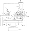
도 1은 연마 장치의 일 실시 형태를 나타내는 측면도이다.
도 2는 연마 헤드를 나타내는 단면도이다.
도 3은 추력과 왜곡 센서의 출력 신호와의 관계를 나타내는 일차함수의 일례를 나타내는 그래프이다.
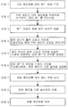
도 4는 패드 서치로부터 웨이퍼의 연마까지의 동작의 일 실시 형태를 설명하는 플로우차트이다.
도 5는 추력을 측정할 때에 사용되는 누름 부재의 측면이다.
도 6은 연마 패드의 연마면 상에 배치된 하중 측정기로서의 로드 셀로, 누름 부재의 추력을 측정하고 있는 모습을 나타내는 도면이다.
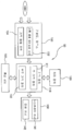
도 7은 동작 제어부의 구성을 나타내는 모식도이다.1 is a side view showing an embodiment of a polishing apparatus.
2 is a cross-sectional view showing the polishing head.
3 is a graph showing an example of a first-order function showing the relationship between the thrust and the output signal of the distortion sensor.
4 is a flowchart for explaining an embodiment of an operation from pad search to polishing of a wafer.
5 is a side view of the pressing member used when measuring the thrust.
It is a figure which shows the state which the thrust of a press member is measured by the load cell as a load measuring device arrange | positioned on the grinding | polishing surface of a polishing pad.
7 is a schematic diagram illustrating a configuration of an operation control unit.
이하에, 본 발명의 실시 형태에 대하여 도면을 참조하여 설명한다.EMBODIMENT OF THE INVENTION Below, embodiment of this invention is described with reference to drawings.
도 1은 연마 장치의 일 실시 형태를 나타내는 측면도이다. 도 1에 나타내는 바와 같이, 연마 장치는, 연마 패드(3)를 지지하는 연마 테이블(2)과, 기판의 일례인 웨이퍼(W)를 보지하여 연마 테이블(2) 상의 연마 패드(3)에 누르는 연마 헤드(기판 보지 장치)(1)를 구비하고 있다.1 is a side view showing an embodiment of a polishing apparatus. As shown in FIG. 1, the polishing apparatus holds the polishing table 2 supporting the
연마 테이블(2)은, 테이블 축(2a)을 개재하여 그 하방에 배치되는 테이블 모터(5)에 연결되어 있고, 그 테이블 축(2a)을 중심으로 회전 가능하게 되어 있다. 연마 패드(3)는 연마 테이블(2)의 상면에 첩부(貼付)되어 있고, 연마 패드(3)의 상면이 웨이퍼(W)를 연마하는 연마면(3a)을 구성하고 있다. 연마 테이블(2)의 상방(上方)에는 연마액 공급 노즐(7)이 설치되어 있고, 이 연마액 공급 노즐(7)에 의해서 연마 패드(3)의 연마면(3a) 상에 연마액(예를 들면, 슬러리)이 공급되도록 되어 있다.The polishing table 2 is connected to the
연마 헤드(1)는, 연마 헤드 샤프트(8)의 하단에 착탈 가능하게 고정되어 있다. 연마 헤드 샤프트(8)는, 액추에이터(15)에 의해 헤드 아암(12)에 대하여 상하 이동하도록 되어 있다. 이 연마 헤드 샤프트(8)의 상하 이동에 의해, 헤드 아암(12)에 대하여 연마 헤드(1)의 전체를 승강시켜 위치 결정하도록 되어 있다. 연마 헤드(1)는, 연마 헤드 샤프트(8) 및 액추에이터(15)를 개재하여 헤드 아암(12)에 지지되어 있다. 연마 헤드 샤프트(8)는 헤드 아암(12)을 관통하여 연장되어 있다.The polishing
액추에이터(15)는, 연마 헤드(1) 및 연마 헤드 샤프트(8)를 헤드 아암(12)에 대하여 상대적으로 이동시키는 것이 가능하다. 액추에이터(15)에 의해서 이동되는 연마 헤드(1)의 방향은, 연마면(3a)에 수직이다. 연마 헤드 샤프트(8)의 상단(上端)에는 로터리 조인트(18)가 장착되어 있다.The
연마 헤드 샤프트(8) 및 연마 헤드(1)를 상하 방향으로 이동시키는 액추에이터(15)는, 지지대(30)에 고정되어 있다. 이 지지대(30)는, 헤드 아암(12)의 상면에 고정되어 있다. 액추에이터(15)는, 연마 헤드 샤프트(8)를 회전 가능하게 지지하는 베어링(20)과, 베어링(20)을 보지하는 브리지(22)와, 브리지(22)에 연결된 볼 나사 기구(24)와, 지지대(30) 상에 고정된 서보 모터(26)를 구비하고 있다.An
볼 나사 기구(24)는, 서보 모터(26)에 연결된 나사축(24a)과, 이 나사축(24a)이 나사 결합하는 너트(24b)를 구비하고 있다. 너트(24b)는 브리지(22)에 보지되어 있다. 연마 헤드 샤프트(8)는, 베어링(20) 및 브리지(22)와 일체로 되어 상하 이동 가능하다. 서보 모터(26)를 구동하면, 볼 나사 기구(24)를 개재하여 브리지(22)가 상하 이동하고, 이에 의해 연마 헤드 샤프트(8) 및 연마 헤드(1)가 상하 이동한다. 연마 헤드(1)는, 연마 헤드 샤프트(8), 액추에이터(15), 및 지지대(30)를 개재하여 헤드 아암(12)에 연결되어 있다.The
연마 헤드 샤프트(8)는, 그 축 방향으로 이동 가능하게 볼 스플라인 베어링(32)에 지지되어 있다. 이 볼 스플라인 베어링(32)의 외주부에는 풀리(35)가 고정되어 있다. 헤드 아암(12)에는 연마 헤드 회전 모터(37)가 고정되어 있고, 상기 풀리(35)는, 연마 헤드 회전 모터(37)에 장착된 풀리(40)에 벨트(39)를 개재하여 접속되어 있다. 따라서, 연마 헤드 회전 모터(37)를 회전 구동함으로써 풀리(40), 벨트(39), 및 풀리(35)를 개재하여 볼 스플라인 베어링(32) 및 연마 헤드 샤프트(8)가 일체로 회전하고, 연마 헤드(1)가 연마 헤드 샤프트(8)를 중심으로 회전한다. 풀리(35, 40), 벨트(39), 및 볼 스플라인 베어링(32)은, 헤드 아암(12) 내에 배치되어 있다.The polishing
헤드 아암(12)은, 프레임(도시 생략)에 지지된 선회축(43)에 의해서 지지되어 있다. 연마 헤드(1)는, 그 하면에 웨이퍼(W)를 보지할 수 있도록 되어 있다. 헤드 아암(12)은 선회축(43)을 중심으로 하여 선회 가능하게 구성되어 있다. 하면에 웨이퍼(W)를 보지한 연마 헤드(1)는, 헤드 아암(12)의 선회에 의해 웨이퍼(W)의 수취 위치로부터 연마 테이블(2)의 상방 위치로 이동된다.The
연마 장치는, 연마 헤드(1), 연마 헤드 회전 모터(37), 서보 모터(26)를 포함하는 각 기기를 제어하는 동작 제어부(50)를 구비하고 있다. 서보 모터(26)는 모터 드라이버(51)에 접속되어 있고, 모터 드라이버(51)는 동작 제어부(50)에 접속되어 있다. 동작 제어부(50)는 모터 드라이버(51)에 지령 신호를 보내고, 모터 드라이버(51)는 지령 신호에 따라서 서보 모터(26)를 구동한다.The polishing apparatus is equipped with the
웨이퍼(W)의 연마는 다음과 같이 하여 행해진다. 연마 헤드(1) 및 연마 테이블(2)을 각각 회전시키고, 연마액 공급 노즐(7)로부터 연마 패드(3)의 연마면(3a) 상에 연마액을 공급한다. 이 상태로, 연마 헤드(1)를 소정의 기준 높이에까지 하강시키고, 그리고 연마 헤드(1)에 의해 웨이퍼(W)를 연마 패드(3)의 연마면(3a)에 가압한다. 웨이퍼(W)는 연마액의 존재 하에서 연마 패드(3)의 연마면(3a)에 슬라이딩 접촉되고, 이에 의해 웨이퍼(W)의 표면이 연마된다.Polishing of the wafer W is performed as follows. The polishing
연마 장치는, 헤드 아암(12)의 휨을 검출하는 왜곡 센서(55)를 구비하고 있다. 왜곡 센서(55)는, 헤드 아암(12)의 휨의 크기에 따라서 변화되는 출력 신호를 생성하도록 구성되어 있다. 이 왜곡 센서(55)는, 헤드 아암(12)에 고정된 센서 헤드(56)와, 센서 헤드(56)에 전기적으로 접속된 센서 앰프(57)를 구비하고 있다. 센서 헤드(56)는, 헤드 아암(12)의 휨을 감지할 수 있는 압전 소자나 금속 저항체 등의 소자를 구비하고 있고, 헤드 아암(12)의 휨의 크기에 따라서 변화되는 전기 신호를 출력한다. 이 전기 신호는 센서 앰프(57)에 보내어지고, 센서 앰프(57)에 의해서 증폭된다.The polishing apparatus is equipped with the
센서 헤드(56)는 헤드 아암(12)의 상면에 고정되어 있다. 일 실시 형태에서는, 센서 헤드(56)는 헤드 아암(12)의 하면에 고정되어도 된다. 헤드 아암(12)의 휨을 정밀도 좋게 감지하기 위하여, 센서 헤드(56)는, 헤드 아암(12)에 가해지는 힘의 작용점인 지지대(30)의 하단(下端)과, 헤드 아암(12)의 지점(支點)인 선회축(43)과의 사이에 있으면 되고, 본 실시예에서는 바람직한 배치로서 헤드 아암(12)의 상면에서 작용점과 지점과의 사이의 대략 중앙에 위치해 있다.The sensor head 56 is fixed to the upper surface of the
왜곡 센서(55)의 출력 신호는, 헤드 아암(12)의 휨의 크기에 따라서 변화된다. 이 출력 신호는, 휨의 크기를 간접적으로 나타내는 전류값 또는 전압값 등의 수치여도 되고, 또는 휨의 크기를 직접 나타내는 수치여도 된다. 왜곡 센서(55)의 구성은 본 실시 형태에 한정되지 않고, 헤드 아암(12)의 휨의 크기에 따라서 변화되는 출력 신호를 생성할 수 있는 것이라면, 다른 구성을 갖는 왜곡 센서를 이용해도 된다. 왜곡 센서(55)는, 센서 앰프(57)로부터 출력된 신호를, 다른 형태의 신호로 변환하는 변환기를 더 구비해도 된다.The output signal of the
왜곡 센서(55)는 동작 제어부(50)에 전기적으로 접속되어 있다. 보다 구체적으로는, 센서 앰프(57)는 동작 제어부(50)에 전기적으로 접속되어 있다. 왜곡 센서(55)의 출력 신호는 동작 제어부(50)에 보내어진다. 왜곡 센서(55)는, 후술하는 바와 같이, 연마 헤드(1)의 상기 기준 높이를 결정하는 공정에 있어서 사용된다.The
연마 장치는, 연마 패드(3)의 연마면(3a)를 드레싱하는 드레싱 유닛(60)을 구비하고 있다. 이 드레싱 유닛(60)은, 연마 패드(3)의 연마면(3a)에 슬라이딩 접촉되는 드레서(61)와, 드레서(61)가 연결된 드레서 샤프트(62)와, 드레서 샤프트(62)의 상단에 마련된 에어 실린더(63)와, 드레서 샤프트(62)를 회전 자유롭게 지지하는 드레서 아암(65)을 구비하고 있다. 드레서(61)의 하면은 드레싱면(61a)을 구성하고, 이 드레싱면(61a)은 연마 입자(예를 들면, 다이아몬드 입자)로 구성되어 있다. 에어 실린더(63)는, 지지대(67) 상에 배치되어 있고, 지지대(67)는 드레서 아암(65)에 고정되어 있다.The polishing apparatus includes a
지축(支軸)(68)에 연결된 도시하지 않은 모터를 구동하면, 드레서 아암(65)은 지축(68)을 중심으로 하여 선회한다. 드레서 샤프트(62)는, 드레서 아암(65) 내에 배치된 도시하지 않은 드레서 회전 모터에 의해 회전하고, 이 드레서 샤프트(62)의 회전에 의해, 드레서(61)가 드레서 샤프트(62)를 중심으로 화살표로 나타내는 방향으로 회전하도록 되어 있다. 에어 실린더(63)는, 드레서 샤프트(62)를 개재하여 드레서(61)에 연결되어 있다. 에어 실린더(63)는, 드레서 샤프트(62) 및 드레서(61)를 일체로 상하 이동시키고, 드레서(61)의 드레싱면(61a)을 소정의 힘으로 연마 패드(3)의 연마면(3a)에 누른다.When the motor (not shown) connected to the
연마 패드(3)의 연마면(3a)의 드레싱은 다음과 같이 하여 행해진다. 연마 패드(3)는 연마 테이블(2)과 함께 테이블 모터(5)에 의해서 회전되면서, 도시하지 않은 순수 공급 노즐로부터 순수가 연마면(3a)에 공급된다. 드레서(61)는, 드레서 샤프트(62)를 중심으로 회전하면서, 드레서(61)의 드레싱면(61a)은 에어 실린더(63)에 의해 연마면(3a)에 가압된다. 연마면(3a) 상에 순수가 존재한 상태로, 드레서(61)는 연마면(3a)에 슬라이딩 접촉된다. 드레서(61)의 회전 중, 드레서 아암(65)을, 지축(68)을 중심으로 하여 선회시켜 드레서(61)를 연마면(3a)의 반경 방향으로 이동시킨다. 이와 같이 하여, 드레서(61)에 의해 연마 패드(3)가 깎아 내어져, 연마면(3a)이 드레싱(재생)된다.Dressing of the polishing
드레싱 유닛(60)은 드레서(61)의 높이(즉, 연마면(3a)에 대한 드레서(61)의 상대적인 세로 방향의 위치)를 측정하는 변위 센서(70)를 구비하고 있다. 이 변위 센서(70)는 드레서 아암(65)에 고정되어 있다. 드레서 샤프트(62)에는 타겟 플레이트(71)가 고정되어 있고, 드레서(61) 및 드레서 샤프트(62)의 상하 이동에 따라서, 타겟 플레이트(71)는 상하 이동하도록 되어 있다. 변위 센서(70)는, 타겟 플레이트(71)를 향하고 있고, 이 타겟 플레이트(71)의 높이(타겟 플레이트(71)의 세로 방향의 위치)를 측정하도록 구성되어 있다.The
에어 실린더(63)를 구동하면, 드레서(61), 드레서 샤프트(62), 및 타겟 플레이트(71)는 일체로 상하 이동한다. 한편, 드레서 아암(65)의 세로 방향의 위치는 고정이다. 변위 센서(70)는, 드레서 아암(65)에 대한 타겟 플레이트(71)의 세로 방향의 위치를 측정함으로써, 드레서(61)의 높이를 간접적으로 측정할 수 있다. 본 실시 형태에서는, 변위 센서(70)로서, 타겟 플레이트(71)에 접촉하는 접촉식 변위 센서가 이용되고 있지만, 타겟 플레이트(71)에 접촉하지 않는 비접촉식 변위 센서를 이용해도 된다. 구체적으로는 리니어 스케일, 레이저식 센서, 초음파 센서, 또는 와(渦)전류식 센서 등을 변위 센서(70)로서 이용할 수 있다.When the
변위 센서(70)는, 동작 제어부(50)에 전기적으로 접속되어 있고, 드레서(61)의 세로 방향의 위치의 측정값은 동작 제어부(50)에 보내어진다. 웨이퍼의 연마 및 연마 패드(3)의 드레싱에 따라서 연마 패드(3)는 서서히 마모된다. 동작 제어부(50)는, 변위 센서(70)로부터 보내어지는 측정값에 기초하여 연마 패드(3)의 감모량을 산출하도록 구성되어 있다. 보다 구체적으로는, 동작 제어부(50)는, 연마면(3a)에 접촉되어 있을 때의 드레서(61)의 세로 방향의 위치의 초기의 측정값과 현재의 측정값과의 차를 산출한다. 이 차는 연마 패드(3)의 감모량에 상당한다.The
다음으로, 연마 헤드(1)에 대하여 도 2를 참조하여 상세하게 설명한다. 도 2는 연마 헤드(1)를 나타내는 단면도이다. 연마 헤드(1)는, 연마 헤드 샤프트(8)에 고정된 헤드 본체(81)와, 헤드 본체(81)의 하방에 배치된 리테이너 링(82)을 구비하고 있다. 헤드 본체(81)의 하부에는, 웨이퍼(W)에 맞닿는 유연한 멤브레인(탄성막)(84)이 고정되어 있다. 멤브레인(84)과 헤드 본체(81) 사이에는, 4개의 압력실(C1, C2, C3, C4)이 형성되어 있다. 압력실(C1, C2, C3, C4)은 멤브레인(84)과 헤드 본체(81)에 의해서 형성되어 있다. 중앙의 압력실(C1)은 원형이고, 다른 압력실(C2, C3, C4)은 환상(環狀)이다. 이들 압력실(C1, C2, C3, C4)은 동심 상에 배열되어 있다. 일 실시 형태에서는, 4개보다 많은 압력실이 마련되어도 되고, 또는, 4개보다 적은 압력실이 마련되어도 된다.Next, the polishing
압력실(C1, C2, C3, C4)에는 각각 유체로(F1, F2, F3, F4)를 통하여 기체 공급원(77)에 의해 압축 공기 등의 압축 기체가 공급되도록 되어 있다. 웨이퍼(W)는, 멤브레인(84)에 의해서 연마 패드(3)의 연마면(3a)에 눌린다. 보다 구체적으로는, 압력실(C1, C2, C3, C4) 내의 압축 기체의 압력은, 멤브레인(84)을 개재하여 웨이퍼(W)에 작용하고, 웨이퍼(W)를 연마면(3a)에 대하여 누른다. 압력실(C1, C2, C3, C4)의 내부 압력은 독립적으로 변화시키는 것이 가능하고, 이에 의해, 웨이퍼(W)의 대응하는 4개의 영역, 즉, 중앙부, 내측 중간부, 외측 중간부, 및 주연(周緣)부에 대한 연마 압력을 독립적으로 조정할 수 있다. 압력실(C1, C2, C3, C4)은, 유체로(F1, F2, F3, F4)를 통하여 도시하지 않은 진공원에 연통(連通)되어 있다.Compression gas such as compressed air is supplied to the pressure chambers C1, C2, C3, and C4 by the
웨이퍼(W)의 주단(周端)부는 리테이너 링(82)에 둘러싸여 있고, 연마 중에 웨이퍼(W)가 연마 헤드(1)로부터 튀어나오지 않도록 되어 있다. 압력실(C3)을 구성하는, 멤브레인(84)의 부위에는 개구가 형성되어 있고, 압력실(C3)에 진공을 형성함으로써 웨이퍼(W)가 연마 헤드(1)에 흡착 보지되도록 되어 있다. 또, 이 압력실(C3)에 질소 가스나 클린 에어 등을 공급함으로써, 웨이퍼(W)가 연마 헤드(1)로부터 릴리스되도록 되어 있다.The peripheral end of the wafer W is surrounded by the
헤드 본체(81)와 리테이너 링(82) 사이에는, 환상의 롤링 다이어프램(88)이 배치되어 있고, 이 롤링 다이어프램(88)의 내부에는 압력실(C5)이 형성되어 있다. 압력실(C5)은, 유체로(F5)를 통하여 상기 기체 공급원(77)에 연결되어 있다. 기체 공급원(77)은 압축 기체를 압력실(C5) 내에 공급하고, 압력실(C5) 내의 압축 기체는 리테이너 링(82)을 연마 패드(3)에 대하여 가압한다.An annular rolling
유체로(F1, F2, F3, F4, F5)는, 압력실(C1, C2, C3, C4, C5)로부터 로터리 조인트(18)를 경유하여 기체 공급원(77)에 연장되어 있다. 유체로(F1, F2, F3, F4, F5)에는, 압력 레귤레이터(R1, R2, R3, R4, R5)가 각각 장착되어 있다. 기체 공급원(77)으로부터의 압축 기체는, 압력 레귤레이터(R1∼R5), 로터리 조인트(18), 및 유체로(F1∼F5)를 통과하여 압력실(C1∼C5) 내에 공급된다. 압력 레귤레이터(R1, R2, R3, R4, R5)는, 압력실(C1, C2, C3, C4, C5) 내의 압력을 제어하도록 구성되어 있다. 압력 레귤레이터(R1, R2, R3, R4, R5)는 동작 제어부(50)에 접속되어 있다. 유체로(F1, F2, F3, F4, F5)는 대기 개방 밸브(도시 생략)에도 접속되어 있어, 압력실(C1, C2, C3, C4, C5)을 대기 개방하는 것도 가능하다.The fluid passages F1, F2, F3, F4, F5 extend from the pressure chambers C1, C2, C3, C4, C5 to the
동작 제어부(50)는, 각 압력실(C1∼C5)의 목표 압력값을 생성하도록 구성되어 있다. 압력실(C1∼C5)의 목표 압력값은, 웨이퍼의 막 두께 측정값에 기초하여 결정된다. 동작 제어부(50)는 목표 압력값을 상기 압력 레귤레이터(R1∼R5)에 보내고, 압력실(C1∼C5) 내의 압력이 대응하는 목표 압력값에 일치하도록 압력 레귤레이터(R1∼R5)가 작동한다. 복수의 압력실(C1, C2, C3, C4)을 갖는 연마 헤드(1)는, 연마의 진척에 따라서 웨이퍼(W)의 표면 상의 각 영역을 독립적으로 연마 패드(3)에 가압할 수 있으므로, 웨이퍼(W)의 막을 균일하게 연마할 수 있다.The
웨이퍼(W)의 연마 중에는 연마 헤드(1)는 기준 높이에 유지된다. 즉, 연마 헤드(1)가 기준 높이에 있는 상태로, 압력실(C1, C2, C3, C4, C5)에 압축 기체가 공급된다. 압력실(C1, C2, C3, C4)을 형성하는 멤브레인(84)은, 웨이퍼(W)를 연마 패드(3)의 연마면(3a)에 대하여 누르고, 압력실(C5)을 형성하는 롤링 다이어프램(88)은, 리테이너 링(82)을 연마 패드(3)의 연마면(3a)에 대하여 누른다.During polishing of the wafer W, the polishing
연마 헤드(1)의 기준 높이는, 연마 패드(3)의 연마면(3a)에 대한 연마 헤드(1)의 전체의 상대적인 높이이다. 연마 헤드(1)의 기준 높이는, 웨이퍼에 가해지는 연마 하중에 영향을 준다. 따라서, 웨이퍼를 연마할 때는, 연마 헤드(1)의 기준 높이는 항상 동일할 필요가 있다. 그러나, 웨이퍼의 연마 및 연마 패드(3)의 드레싱에 따라서 연마 패드(3)는 서서히 마모되고, 결과적으로 연마 헤드(1)의 기준 높이가 변화되어 버린다. 그래서, 연마 패드(3)의 마모에 관계 없이 연마 헤드(1)의 기준 높이가 일정하게 유지되도록, 연마 패드(3)의 감모량에 따라서 연마 헤드(1)의 기준 높이가 조절된다.The reference height of the polishing
연마 헤드(1)의 기준 높이는, 연마 패드(3)가 마모되기 전에(즉, 연마 패드(3)가 웨이퍼 연마에 사용되기 전에) 결정된다. 연마 헤드(1)의 기준 높이를 결정하기 위해서는, 먼저, 연마 패드(3)의 연마면(3a)을 검출할 필요가 있다. 본 명세서에서는, 연마 패드(3)의 연마면(3a)을 검출하는 작업을, 패드 서치라고 부른다.The reference height of the polishing
패드 서치는 연마 헤드(1)를 이용하여 행해진다. 구체적으로는, 패드 서치는, 연마 헤드(1)가 연마 패드(3)에 추력을 가하면서 행해진다. 연마 헤드(1)의 추력은, 상술한 액추에이터(15)(보다 구체적으로는 서보 모터(26))에 의해서 발생된다. 연마 헤드(1)는 연마 패드(3)로부터 반력을 받는다. 이 반력은, 연마 헤드 샤프트(8), 액추에이터(15), 및 지지대(30)를 거쳐 헤드 아암(12)에 전달된다. 그 결과, 헤드 아암(12)은 상 방향으로 휜다. 상술한 왜곡 센서(55)는, 이 헤드 아암(12)의 휨에 상당하는 출력 신호를 생성하고, 이 출력 신호를 동작 제어부(50)에 보낸다. 동작 제어부(50)는, 추력과 왜곡 센서(55)의 출력 신호와의 관계를 나타내는 일차함수를 미리 기억하고 있다. 따라서, 동작 제어부(50)는, 왜곡 센서(55)의 출력 신호에 기초하여, 연마 헤드(1)로부터 연마 패드(3)에 가해지고 있는 추력을 결정할 수 있다.The pad search is performed using the polishing
도 3은, 추력과 왜곡 센서(55)의 출력 신호와의 관계를 나타내는 일차함수의 일례를 나타내는 그래프이다. 도 3의 종축은 연마 헤드(1)로부터 연마 패드(3)에 작용하는 추력(하중)을 나타내고, 횡축은 왜곡 센서(55)의 출력 신호를 나타낸다. 출력 신호는, 헤드 아암(12)의 휨의 크기를 직접 또는 간접적으로 나타내는 수치로 구성된다. 도 3에 나타내는 바와 같이, 추력은 왜곡 센서(55)의 출력 신호에 비례한다. 따라서, 동작 제어부(50)는, 왜곡 센서(55)의 출력 신호와 일차함수로부터 추력을 결정할 수 있다.3 is a graph showing an example of a first-order function showing the relationship between the thrust and the output signal of the
도 4는, 패드 서치로부터 웨이퍼의 연마까지의 동작의 일 실시 형태를 설명하는 플로우차트이다. 단계 1에서는, 연마 헤드(1)는, 더미 웨이퍼(더미 기판)를 멤브레인(84) 상에 보지한다. 더미 웨이퍼(더미 기판)는, 미리 정해진 두께를 갖는 웨이퍼(기판)이다. 더미 웨이퍼(더미 기판) 대신에, 미리 정해진 두께를 갖는 제품 웨이퍼(제품 기판)를 이용해도 된다.4 is a flowchart illustrating an embodiment of an operation from pad search to polishing of a wafer. In
단계 2에서는, 연마 헤드(1)로 더미 웨이퍼를 연마면(3a)에 누르면서, 연마 헤드(1)를 하강(이동)시킨다. 보다 구체적으로는, 동작 제어부(50)는 모터 드라이버(51)에 지령 신호를 보내어, 액추에이터(15)를 작동시킨다. 액추에이터(15)는, 연마 헤드(1)를 소정의 속도로 연마 패드(3)의 연마면(3a)을 향하여 하강시켜, 연마 헤드(1)로 더미 웨이퍼를 연마면(3a)에 누른다. 이 때 연마 헤드(1) 및 연마 테이블(2)은 회전하고 있지 않다. 연마 헤드(1)가 더미 웨이퍼를 연마면(3a)에 누르고 있는 동안, 연마 헤드(1)는 상기 소정의 속도로 하강을 계속한다. 이 때의 연마 헤드(1)의 이동 방향은 연마면(3a)과 수직이다. 연마 헤드(1)가 더미 웨이퍼를 연마면(3a)에 누르고 있는 동안, 연마 헤드(1)의 압력실(C1-C5) 내는 대기 개방된다. 연마 헤드(1)의 추력은, 더미 웨이퍼를 통하여 연마 패드(3)의 연마면(3a)에 가해진다. 리테이너 링(82)은, 그 자중(自重)에 의해 단지 연마면(3a)에 접촉한다.In
단계 3에서는, 연마 헤드(1)의 이동 중에, 왜곡 센서(55)는 헤드 아암(12)의 휨을 검출한다. 상기 단계 2와 단계 3은 실제로는 동시에 행해진다. 연마 헤드(1)가 하강함에 따라서, 연마 헤드(1)로부터 연마 패드(3)의 연마면(3a)에 가해지는 추력은 커진다. 환언하면, 연마 패드(3)로부터 연마 헤드(1)에 가해지는 반력은, 연마 헤드(1)의 하강에 따라서 커진다. 이 반력은 헤드 아암(12)을 상방으로 휘게 한다. 왜곡 센서(55)는 헤드 아암(12)의 휨의 크기를 반영한 출력 신호를 동작 제어부(50)에 보낸다.In
단계 4에서는, 동작 제어부(50)는, 왜곡 센서(55)로부터의 출력 신호가 미리 설정된 역치에 도달하였을 때에, 모터 드라이버(51)에 지령 신호를 보내고, 연마 헤드(1)의 이동(하강)을 정지시킨다.In step 4, when the output signal from the
단계 5에서는, 동작 제어부(50)는, 왜곡 센서(55)로부터의 출력 신호가 미리 설정된 역치에 도달한 시점에 대응하는 연마 헤드(1)의 위치를 결정한다. 연마 헤드(1)의 위치는, 연마 패드(3)의 연마면(3a)에 대한 연마 헤드(1)의 전체의 상대적인 높이이다. 연마 헤드(1)의 위치는, 서보 모터(26)의 회전 횟수와 볼 나사 기구(24)의 나사 피치로부터 구해진다.In
단계 6에서는, 동작 제어부(50)는, 결정된 연마 헤드(1)의 위치에 소정의 거리를 가산함으로써, 연마면(3a)에 대한 연마 헤드(1)의 기준 높이를 결정한다. 소정의 거리는, 연마면(3a)으로부터 멀어지는 방향의 거리이다.In step 6, the
단계 7에서는, 연마 헤드(1)는, 더미 웨이퍼 대신에, 제품 웨이퍼를 보지한다.In step 7, the polishing
단계 8에서는, 동작 제어부(50)는, 모터 드라이버(51)에 지령 신호를 보내고, 액추에이터(15)를 작동시켜, 연마 헤드(1)를 상기 결정된 기준 높이까지 이동시킨다.In
단계 9에서는, 연마액 공급 노즐(7)은, 회전하는 연마 테이블(2) 상의 연마 패드(3)의 연마면(3a)에 연마액을 공급하면서, 기준 높이에 있는 연마 헤드(1)는 제품 웨이퍼를 연마면(3a)에 누름으로써, 제품 웨이퍼를 연마한다.In step 9, the polishing liquid supply nozzle 7 supplies the polishing liquid to the polishing
헤드 아암(12)의 휨의 크기는, 연마 헤드(1)로부터 연마 패드(3)에 가해지는 추력에 의존하고, 다른 요인에 의존하지 않는다. 따라서, 추력이 동일한 한, 헤드 아암(12)의 휨의 크기도 시간 경과에 관계없이 동일하다. 왜곡 센서(55)의 출력 신호는, 시간의 경과에 영향받지 않고, 헤드 아암(12)의 휨의 크기, 즉 추력을 정확하게 반영한다. 결과적으로, 동작 제어부(50)는, 패드 서치를 행할 때마다 정확한 연마 헤드(1)의 기준 높이를 결정할 수 있다.The magnitude of the warp of the
패드 서치 및 연마 헤드(1)의 기준 높이의 결정은, 연마 패드(3)를 새로운 것으로 교환할 때마다 행해진다. 보다 구체적으로는, 새로운 연마 패드(3)가 연마 테이블(2) 상에 장착된 후, 드레서(61)에 의해 새로운 연마 패드(3)의 연마면(3a)이 드레싱된다. 그 후, 패드 서치 및 연마 헤드(1)의 기준 높이의 결정이 실행된다.The pad search and the determination of the reference height of the polishing
상술한 바와 같이, 웨이퍼의 연마 및 연마 패드(3)의 드레싱에 따라서 연마 패드(3)는 서서히 마모되고, 결과적으로 연마 헤드(1)의 기준 높이가 변화되어 버린다. 그래서, 연마 패드(3)의 마모에 관계 없이 연마 헤드(1)의 기준 높이가 일정하게 유지되도록, 연마 헤드(1)의 감모량에 따라서 연마 헤드(1)의 기준 높이가 조절된다. 구체적으로는, 1매 또는 소정의 매수의 웨이퍼가 연마될 때마다, 동작 제어부(50)는, 연마 패드(3)의 감모량을 산출하고, 감모량을 연마 헤드(1)의 기준 높이로부터 감산함으로써, 연마 헤드(1)의 기준 높이를 갱신한다. 이와 같은 동작에 의해, 연마 패드(3)의 마모에 영향받지 않고, 연마 헤드(1)의 기준 높이를 항상 일정하게 유지할 수있다.As described above, the
도 3에 나타내는 일차함수는, 다른 복수의 추력을 실제로 측정하고, 이들 추력에 대응하는 왜곡 센서(55)의 복수의 출력 신호를 취득하고, 추력의 측정값 및 대응하는 출력 신호로부터 특정되는 좌표점을 좌표계 상에 플롯하고, 이들 좌표점에 회귀 분석을 실행함으로써 얻어진다. 추력과 왜곡 센서(55)의 출력 신호와의 관계를 나타내는 일차함수는, 패드 서치 전에 취득된다. 추력과 왜곡 센서(55)의 출력 신호와의 관계가 일단 취득되면, 그 관계(일차함수로 나타내어짐)는, 그 후에 행해지는 복수의 패드 서치에 사용할 수 있다.The primary function shown in FIG. 3 actually measures a plurality of different thrusts, obtains a plurality of output signals of the
추력을 측정할 때, 연마 헤드(1)가 연마 헤드 샤프트(8)로부터 떼어지고, 도 5에 나타내는 누름 부재(91)가 연마 헤드 샤프트(8)에 고정된다. 누름 부재(91)는, 도시하지 않은 나사에 의해 연마 헤드 샤프트(8)의 하단에 고정된다. 도 5에 나타내는 바와 같이, 누름 부재(91)는 구면 형상의 가압면(91a)을 갖는다. 이 가압면(91a)은 누름 부재(91)의 하면을 구성한다. 구면 형상의 가압면(91a)의 최하점은, 누름 부재(91)의 중심 및 연마 헤드 샤프트(8)의 중심축에 일치한다.When the thrust is measured, the polishing
도 6은, 연마 패드(3)의 연마면(3a) 상에 배치된 하중 측정기로서의 로드 셀(95)에 의해, 누름 부재(91)의 추력을 측정하고 있는 모습을 나타내는 도면이다. 로드 셀(95)과 누름 부재(91) 사이에는 스페이서(93)가 배치되어 있다. 스페이서(93)는 생략해도 된다. 액추에이터(15)(도 1 참조)를 작동시킴으로써, 누름 부재(91)의 가압면(91a)은 스페이서(93)을 개재하여 로드 셀(95)을 누른다. 누름 부재(91)의 가압면(91a)은 스페이서(93)에 점 접촉한다. 이 때의 누름 부재(91)의 추력은, 연마 헤드(1)의 추력에 상당한다. 로드 셀(95)은 누름 부재(91)의 추력(하중)을 측정한다.FIG. 6: is a figure which shows the state in which the thrust force of the pressing
도 6으로부터 알 수 있는 바와 같이, 가압면(91a)은 구(球) 형상이므로, 누름 부재(91)의 중심만이 스페이서(93)에 접촉한다. 만약 가압면(91a)이 평면이면, 연마 헤드 샤프트(8)가 연마면(3a)에 대하여 완전히 수직이 아닌 한, 추력의 작용점이 연마 헤드 샤프트(8)의 중심축으로부터 벗어나 버려, 로드 셀(95)은 정확한 추력을 측정할 수 없다. 본 실시 형태에 의하면, 추력의 작용점은 연마 헤드 샤프트(8)의 중심축 상에 있으므로, 로드 셀(95)은 정확한 추력을 측정할 수 있다.As can be seen from FIG. 6, since the
본 실시 형태에서는, 동작 제어부(50)는, 전용의 컴퓨터 또는 범용의 컴퓨터로 구성된다. 도 7은 동작 제어부(50)의 구성을 나타내는 모식도이다. 동작 제어부(50)는, 프로그램이나 데이터 등이 격납되는 기억 장치(110)와, 기억 장치(110)에 격납되어 있는 프로그램에 따라서 연산을 행하는 CPU(중앙 처리 장치) 등의 처리 장치(120)와, 데이터, 프로그램, 및 각종 정보를 기억 장치(110)에 입력하기 위한 입력 장치(130)와, 처리 결과나 처리된 데이터를 출력하기 위한 출력 장치(140)와, 인터넷 등의 네트워크에 접속하기 위한 통신 장치(150)를 구비하고 있다.In the present embodiment, the
기억 장치(110)는, 처리 장치(120)가 액세스 가능한 주 기억 장치(111)와, 데이터 및 프로그램을 격납하는 보조 기억 장치(112)를 구비하고 있다. 주 기억 장치(111)는, 예를 들면, 랜덤 액세스 메모리(RAM)이고, 보조 기억 장치(112)는, 하드 디스크 드라이브(HDD) 또는 솔리드 스테이트 드라이브(SSD) 등의 스토리지 장치이다.The
입력 장치(130)는, 키보드, 마우스를 구비하고 있고, 또한, 기록 매체로부터 데이터를 읽어들이기 위한 기록 매체 읽어들임 장치(132)와, 기록 매체가 접속되는 기록 매체 포트(134)를 구비하고 있다. 기록 매체는, 비일시적인 유형물인 컴퓨터 판독 가능한 기록 매체이며, 예를 들면, 광 디스크(예를 들면, CD-ROM, DVD-ROM)나 반도체 메모리(예를 들면, USB 플래시 드라이브, 메모리 카드)이다. 기록 매체 읽어들임 장치(132)의 예로서는 CD 드라이브, DVD 드라이브 등의 광학 드라이브나 카드 리더를 들 수 있다. 기록 매체 포트(134)의 예로서는 USB 단자를 들 수 있다. 기록 매체에 기억되어 있는 프로그램 및/또는 데이터는, 입력 장치(130)를 통하여 동작 제어부(50)에 도입되고, 기억 장치(110)의 보조 기억 장치(112)에 격납된다. 출력 장치(140)는 디스플레이 장치(141), 인쇄 장치(142)를 구비하고 있다.The
기억 장치(110)는, 왜곡 센서(55)로부터의 출력 신호가 미리 설정된 역치에 도달한 시점에 대응하는 연마 헤드(1)의 위치를 결정하고, 당해 결정된 연마 헤드(1)의 위치로부터 기준 높이를 결정하기 위한 프로그램을 내부에 격납하고 있다. 이 프로그램은 처리 장치(120)에 의해서 실행된다. 또한, 기억 장치(110)는, 연마 헤드(1)로부터 연마 패드(3)에 가해지는 추력과, 왜곡 센서(55)의 출력 신호와의 관계를 나타내는 일차함수를 내부에 기억하고 있다.The
상기 프로그램은, 비일시적인 유형물인 컴퓨터 판독 가능한 기록 매체에 기록되고, 기록 매체를 통하여 동작 제어부(50)에 제공된다. 또는, 프로그램은, 인터넷 등의 통신 네트워크를 통하여 동작 제어부(50)에 제공되어도 된다.The program is recorded on a non-transitory tangible computer readable recording medium and provided to the
상술한 실시 형태는, 본 발명이 속하는 기술 분야에 있어서의 통상의 지식을 가진 자가 본 발명을 실시할 수 있는 것을 목적으로 하여 기재된 것이다. 상기 실시 형태의 여러 가지 변형례는, 당업자라면 당연히 이룰 수 있는 것이며, 본 발명의 기술적 사상은 다른 실시 형태에도 적용할 수 있다. 따라서, 본 발명은, 기재된 실시 형태에 한정되지는 않고, 특허청구의 범위에 의해서 정의되는 기술적 사상에 따른 가장 넓은 범위로 해석되는 것이다.The above-described embodiment is described for the purpose of carrying out the present invention by a person having ordinary knowledge in the technical field to which the present invention belongs. Various modifications of the above embodiments can be naturally made by those skilled in the art, and the technical idea of the present invention can be applied to other embodiments. Therefore, this invention is not limited to embodiment described, It is interpreted in the widest range according to the technical idea defined by the claim.
1: 연마 헤드(기판 보지 장치)
2: 연마 테이블
2a: 테이블 축
3: 연마 패드
3a: 연마면
5: 테이블 모터
7: 연마액 공급 노즐
8: 연마 헤드 샤프트
12: 헤드 아암
15: 액추에이터
18: 로터리 조인트
20: 베어링
22: 브리지
24: 볼 나사 기구
24a: 나사축
24b: 너트
26: 서보 모터
30: 지지대
32: 볼 스플라인 베어링
35: 풀리
37: 연마 헤드 회전 모터
39: 벨트
40: 풀리
43: 선회축
50: 동작 제어부
51: 모터 드라이버
55: 왜곡 센서
56: 센서 헤드
57: 센서 앰프
60: 드레싱 유닛
61: 드레서
61a: 드레싱면
62: 드레서 샤프트
63: 에어 실린더
65: 드레서 아암
67: 지지대
68: 지축
70: 변위 센서
71: 타겟 플레이트
77: 기체 공급원
81: 헤드 본체
82: 리테이너 링
84: 멤브레인
88: 롤링 다이어프램
91: 누름 부재
91a: 가압면
93: 스페이서
95: 로드 셀
F1, F2, F3, F4, F5: 유체로
C1, C2, C3, C4, C5: 압력실
R1, R2, R3, R4, R5: 압력 레귤레이터1: Polishing head (substrate holding device)
2: polishing table
2a: table axis
3: polishing pad
3a: polishing surface
5: table motor
7: polishing liquid supply nozzle
8: polishing head shaft
12: head arm
15: Actuator
18: rotary joint
20: bearing
22: bridge
24: ball screw mechanism
24a: screw shaft
24b: nut
26: servo motor
30: support
32: ball spline bearing
35: pulley
37: polishing head rotary motor
39: belt
40: pulley
43: pivot
50: operation control unit
51: motor driver
55: distortion sensor
56: sensor head
57: sensor amplifier
60: dressing unit
61: dresser
61a: dressing cotton
62: dresser shaft
63: air cylinder
65: dresser arm
67: support
68: axis
70: displacement sensor
71: target plate
77: gas source
81: head body
82: retainer ring
84: membrane
88: rolling diaphragm
91: pressing member
91a: pressing surface
93: spacer
95: load cell
F1, F2, F3, F4, F5: With fluid
C1, C2, C3, C4, C5: pressure chamber
R1, R2, R3, R4, R5: Pressure Regulator
Claims (10)
상기 연마 헤드의 이동 중에, 상기 연마 헤드를 지지하는 헤드 아암의 휨을 왜곡 센서에 의해 검출하고,
상기 왜곡 센서로부터의 출력 신호가 미리 설정된 역치에 도달한 시점에 대응하는 상기 연마 헤드의 위치를 결정하는 방법.While applying the thrust from the polishing head to the polishing pad, the polishing head is moved in a direction perpendicular to the polishing surface of the polishing pad,
During the movement of the polishing head, the warp of the head arm supporting the polishing head is detected by a distortion sensor,
And determine the position of the polishing head corresponding to the point in time when the output signal from the distortion sensor reaches a preset threshold.
상기 연마 헤드에 보지된 기판이 상기 연마면에 접촉한 상태로, 상기 연마 헤드를 상기 연마 패드의 상기 연마면에 수직인 방향으로 이동시키는, 방법.The method of claim 1,
And the polishing head is moved in a direction perpendicular to the polishing surface of the polishing pad while the substrate held by the polishing head is in contact with the polishing surface.
상기 결정된 위치에 소정의 거리를 더함으로써, 상기 연마면에 대한 상기 연마 헤드의 기준 높이를 결정하는 공정을 더 포함하는, 방법.The method according to claim 1 or 2,
Determining a reference height of the polishing head relative to the polishing surface by adding a predetermined distance to the determined position.
상기 연마 패드의 감모량을 산출하고,
상기 감모량을 상기 연마 헤드의 기준 높이로부터 감산함으로써, 상기 연마 헤드의 기준 높이를 갱신하는 공정을 더 포함하는, 방법.The method of claim 3, wherein
Calculating the amount of wear of the polishing pad,
And subtracting the amount of wear from the reference height of the polishing head to update the reference height of the polishing head.
상기 연마 헤드로부터 상기 연마 패드에 가해지는 추력과, 상기 왜곡 센서의 출력 신호와의 관계를 취득하는 공정을 더 포함하는, 방법.The method according to claim 1 or 2,
And obtaining a relationship between a thrust applied to the polishing pad from the polishing head and an output signal of the distortion sensor.
상기 추력과 상기 왜곡 센서의 출력 신호와의 관계를 취득하는 공정은,
상기 연마 헤드 대신에 연마 헤드 샤프트에 장착된 누름 지그로, 상기 연마면 상의 하중 측정기를 복수의 다른 하중으로 누르면서, 상기 왜곡 센서의 대응하는 복수의 출력 신호를 취득하고,
상기 하중 측정기로부터 출력된 상기 복수의 다른 하중의 측정값과, 상기 대응하는 복수의 출력 신호에 기초하여, 상기 추력과 상기 왜곡 센서의 출력 신호와의 관계를 나타내는 일차함수를 결정하는 공정을 포함하는, 방법.The method of claim 5,
The process of acquiring the relationship between the thrust and the output signal of the distortion sensor,
The pressing jig mounted on the polishing head shaft instead of the polishing head acquires a corresponding plurality of output signals of the distortion sensor while pressing the load measuring device on the polishing surface with a plurality of different loads,
Determining a primary function indicating a relationship between the thrust and an output signal of the distortion sensor based on the measured values of the plurality of different loads output from the load meter and the corresponding plurality of output signals. , Way.
상기 누름 지그는, 구면 형상의 가압면을 갖는, 방법.The method of claim 6,
The pressing jig has a spherical shape pressing surface.
기판을 상기 연마 패드에 누르기 위한 연마 헤드와,
상기 연마 헤드를 상기 연마 패드의 연마면을 향하여 이동시키는 액추에이터와,
상기 연마 헤드를 지지하는 헤드 아암과,
상기 헤드 아암의 휨을 검출하는 왜곡 센서와,
상기 왜곡 센서에 전기적으로 접속된 동작 제어부를 구비하며,
상기 동작 제어부는, 상기 왜곡 센서로부터의 출력 신호가 미리 설정된 역치에 도달한 시점에 대응하는 상기 연마 헤드의 위치를 결정하기 위한 프로그램이 격납된 기억 장치와, 상기 프로그램을 실행하기 위한 처리 장치를 갖는 연마 장치.A polishing table for supporting the polishing pad,
A polishing head for pressing a substrate onto the polishing pad,
An actuator for moving the polishing head toward the polishing surface of the polishing pad;
A head arm supporting the polishing head;
A distortion sensor for detecting bending of the head arm;
An operation controller electrically connected to the distortion sensor,
The operation control unit includes a storage device in which a program for determining the position of the polishing head corresponding to the point in time when the output signal from the distortion sensor reaches a preset threshold, and a processing device for executing the program. Polishing device.
상기 왜곡 센서는, 상기 헤드 아암의 상면 또는 하면에 고정된 센서 헤드를 구비하고, 상기 센서 헤드는 상기 헤드 아암의 휨을 감지하도록 구성되어 있는, 연마 장치.The method of claim 8,
And the distortion sensor has a sensor head fixed to an upper or lower surface of the head arm, and the sensor head is configured to detect the bending of the head arm.
상기 기억 장치는, 상기 연마 헤드로부터 상기 연마 패드에 가해지는 추력과, 상기 왜곡 센서의 출력 신호와의 관계를 나타내는 일차함수를 내부에 기억하고 있는, 연마 장치.The method according to claim 8 or 9,
And the storage device stores therein a primary function indicating a relation between a thrust applied to the polishing pad from the polishing head and an output signal of the distortion sensor.
Applications Claiming Priority (2)
| Application Number | Priority Date | Filing Date | Title |
|---|---|---|---|
| JPJP-P-2018-096000 | 2018-05-18 | ||
| JP2018096000A JP2019198938A (en) | 2018-05-18 | 2018-05-18 | Method for detecting polished surface of polishing pad by using polishing head, and polishing device |
Publications (1)
| Publication Number | Publication Date |
|---|---|
| KR20190132245A true KR20190132245A (en) | 2019-11-27 |
Family
ID=68534563
Family Applications (1)
| Application Number | Title | Priority Date | Filing Date |
|---|---|---|---|
| KR1020190056958A KR20190132245A (en) | 2018-05-18 | 2019-05-15 | Method of detecting a polishing surface of a polishing pad using a polishing head, and polishing apparatus |
Country Status (5)
| Country | Link |
|---|---|
| US (1) | US20190351526A1 (en) |
| JP (1) | JP2019198938A (en) |
| KR (1) | KR20190132245A (en) |
| CN (1) | CN110497307A (en) |
| TW (1) | TW202003157A (en) |
Families Citing this family (8)
| Publication number | Priority date | Publication date | Assignee | Title |
|---|---|---|---|---|
| CN111085931A (en) * | 2019-12-31 | 2020-05-01 | 浙江芯晖装备技术有限公司 | Polishing head driving device and polishing equipment |
| EP3919192B1 (en) * | 2020-06-04 | 2023-11-29 | Sugino Machine Limited | Cleaning apparatus |
| KR20220029906A (en) * | 2020-09-02 | 2022-03-10 | 에스케이하이닉스 주식회사 | Apparatus and method for planarizing of substrate |
| JP2022108789A (en) | 2021-01-14 | 2022-07-27 | 株式会社荏原製作所 | Polishing device, polishing method, and method for outputting visualized information on film thickness distribution of base plate |
| CN113458972A (en) * | 2021-07-28 | 2021-10-01 | 北京烁科精微电子装备有限公司 | Polishing pad dressing device and polishing equipment |
| CN114633206A (en) * | 2022-04-25 | 2022-06-17 | 北京烁科精微电子装备有限公司 | Trimming device and wafer polishing system |
| CN114918832B (en) * | 2022-05-20 | 2023-07-28 | 湖州师范学院 | High-precision grinding wheel dressing equipment |
| CN117718876B (en) * | 2024-02-07 | 2024-06-18 | 华海清科股份有限公司 | Monitoring method for chemical mechanical polishing and chemical mechanical polishing equipment |
Citations (1)
| Publication number | Priority date | Publication date | Assignee | Title |
|---|---|---|---|---|
| JP2014097553A (en) | 2012-11-15 | 2014-05-29 | Ebara Corp | Substrate holding device and polishing device |
Family Cites Families (14)
| Publication number | Priority date | Publication date | Assignee | Title |
|---|---|---|---|---|
| FR2629746B1 (en) * | 1988-04-06 | 1991-01-25 | Bertin & Cie | METHOD AND DEVICE FOR POLISHING AN OPTICAL COMPONENT |
| US6855032B1 (en) * | 2003-11-24 | 2005-02-15 | Nikon Corporation | Fine force control of actuators for chemical mechanical polishing apparatuses |
| US20050197045A1 (en) * | 2003-11-24 | 2005-09-08 | Novak W. T. | Fine force control of actuators for chemical mechanical polishing apparatuses |
| US7172493B2 (en) * | 2003-11-24 | 2007-02-06 | Nikon Corporation | Fine force actuator assembly for chemical mechanical polishing apparatuses |
| US7059939B2 (en) * | 2004-09-02 | 2006-06-13 | Taiwan Semiconductor Manufacturing Co., Ltd. | Polishing pad conditioner and monitoring method therefor |
| JP4597634B2 (en) * | 2004-11-01 | 2010-12-15 | 株式会社荏原製作所 | Top ring, substrate polishing apparatus and polishing method |
| JP4817687B2 (en) * | 2005-03-18 | 2011-11-16 | 株式会社荏原製作所 | Polishing equipment |
| CN101934491B (en) * | 2004-11-01 | 2012-07-25 | 株式会社荏原制作所 | Polishing apparatus |
| CN2807472Y (en) * | 2005-08-02 | 2006-08-16 | 童德黉 | Pressure spiral arms structure |
| CN102101265B (en) * | 2010-12-16 | 2012-05-16 | 浙江工业大学 | Clamp for detecting stress of polished workpiece and positioning working original point of polishing tool |
| JP5454513B2 (en) * | 2011-05-27 | 2014-03-26 | 信越半導体株式会社 | Method for adjusting position of polishing head in height direction and method for polishing workpiece |
| JP2013111701A (en) * | 2011-11-29 | 2013-06-10 | Hitachi Koki Co Ltd | Portable cutting machine |
| JP6012104B2 (en) * | 2012-12-18 | 2016-10-25 | 三菱日立パワーシステムズ株式会社 | Burnishing apparatus and burnishing method using the same |
| JP6357260B2 (en) * | 2016-09-30 | 2018-07-11 | 株式会社荏原製作所 | Polishing apparatus and polishing method |
-
2018
- 2018-05-18 JP JP2018096000A patent/JP2019198938A/en active Pending
-
2019
- 2019-05-10 US US16/408,960 patent/US20190351526A1/en not_active Abandoned
- 2019-05-15 KR KR1020190056958A patent/KR20190132245A/en not_active Application Discontinuation
- 2019-05-15 TW TW108116736A patent/TW202003157A/en unknown
- 2019-05-15 CN CN201910404342.2A patent/CN110497307A/en active Pending
Patent Citations (1)
| Publication number | Priority date | Publication date | Assignee | Title |
|---|---|---|---|---|
| JP2014097553A (en) | 2012-11-15 | 2014-05-29 | Ebara Corp | Substrate holding device and polishing device |
Also Published As
| Publication number | Publication date |
|---|---|
| CN110497307A (en) | 2019-11-26 |
| US20190351526A1 (en) | 2019-11-21 |
| TW202003157A (en) | 2020-01-16 |
| JP2019198938A (en) | 2019-11-21 |
Similar Documents
| Publication | Publication Date | Title |
|---|---|---|
| KR20190132245A (en) | Method of detecting a polishing surface of a polishing pad using a polishing head, and polishing apparatus | |
| JP6196858B2 (en) | Polishing method and polishing apparatus | |
| KR101512427B1 (en) | Dressing apparatus, dressing method, and polishing apparatus | |
| JP5161294B2 (en) | Chemical mechanical polishing apparatus and chemical mechanical polishing method | |
| US10987776B2 (en) | Calibration method and non-transitory computer-readable storage medium storing a program of calibration | |
| US11679472B2 (en) | Method for CMP pad conditioning | |
| TW411299B (en) | Wafer polishing apparatus and polishing quantity detection method | |
| KR20220155340A (en) | How to create a chemical mechanical polishing system of a workpiece, an operation system, and a simulation model of chemical mechanical polishing | |
| JP7315332B2 (en) | Surface height measurement method using dummy disk and dummy disk | |
| JP6961343B2 (en) | Polishing equipment | |
| US20200368874A1 (en) | Polishing apparatus and polishing method | |
| US20230381910A1 (en) | Method for estimating life of polishing pad and polishing device | |
| WO2022259913A1 (en) | Method for creating polishing rate responsiveness profile of workpiece, polishing method, and computer-readable recording medium having program stored thereon | |
| US20240198480A1 (en) | Method of creating responsive profile of polishing rate of workpiece, polishing method, and polishing apparatus | |
| JPH09193003A (en) | Polishing device | |
| JP4504224B2 (en) | Holder evaluation device | |
| JP2005081461A (en) | Polishing method and device of wafer or the like | |
| JP2020192634A (en) | Method for adjusting height of polishing head and polishing method |
Legal Events
| Date | Code | Title | Description |
|---|---|---|---|
| A201 | Request for examination | ||
| WITB | Written withdrawal of application |