JP6012104B2 - Burnishing apparatus and burnishing method using the same - Google Patents
Burnishing apparatus and burnishing method using the same Download PDFInfo
- Publication number
- JP6012104B2 JP6012104B2 JP2012276072A JP2012276072A JP6012104B2 JP 6012104 B2 JP6012104 B2 JP 6012104B2 JP 2012276072 A JP2012276072 A JP 2012276072A JP 2012276072 A JP2012276072 A JP 2012276072A JP 6012104 B2 JP6012104 B2 JP 6012104B2
- Authority
- JP
- Japan
- Prior art keywords
- pressing force
- burnishing
- force
- pressing
- tool
- Prior art date
- Legal status (The legal status is an assumption and is not a legal conclusion. Google has not performed a legal analysis and makes no representation as to the accuracy of the status listed.)
- Active
Links
Images


Classifications
-
- B—PERFORMING OPERATIONS; TRANSPORTING
- B24—GRINDING; POLISHING
- B24B—MACHINES, DEVICES, OR PROCESSES FOR GRINDING OR POLISHING; DRESSING OR CONDITIONING OF ABRADING SURFACES; FEEDING OF GRINDING, POLISHING, OR LAPPING AGENTS
- B24B39/00—Burnishing machines or devices, i.e. requiring pressure members for compacting the surface zone; Accessories therefor
- B24B39/003—Burnishing machines or devices, i.e. requiring pressure members for compacting the surface zone; Accessories therefor the working tool being composed of a plurality of working rolls or balls
-
- B—PERFORMING OPERATIONS; TRANSPORTING
- B23—MACHINE TOOLS; METAL-WORKING NOT OTHERWISE PROVIDED FOR
- B23P—METAL-WORKING NOT OTHERWISE PROVIDED FOR; COMBINED OPERATIONS; UNIVERSAL MACHINE TOOLS
- B23P9/00—Treating or finishing surfaces mechanically, with or without calibrating, primarily to resist wear or impact, e.g. smoothing or roughening turbine blades or bearings; Features of such surfaces not otherwise provided for, their treatment being unspecified
- B23P9/02—Treating or finishing by applying pressure, e.g. knurling
-
- B—PERFORMING OPERATIONS; TRANSPORTING
- B24—GRINDING; POLISHING
- B24B—MACHINES, DEVICES, OR PROCESSES FOR GRINDING OR POLISHING; DRESSING OR CONDITIONING OF ABRADING SURFACES; FEEDING OF GRINDING, POLISHING, OR LAPPING AGENTS
- B24B39/00—Burnishing machines or devices, i.e. requiring pressure members for compacting the surface zone; Accessories therefor
- B24B39/02—Burnishing machines or devices, i.e. requiring pressure members for compacting the surface zone; Accessories therefor designed for working internal surfaces of revolution
-
- G—PHYSICS
- G05—CONTROLLING; REGULATING
- G05B—CONTROL OR REGULATING SYSTEMS IN GENERAL; FUNCTIONAL ELEMENTS OF SUCH SYSTEMS; MONITORING OR TESTING ARRANGEMENTS FOR SUCH SYSTEMS OR ELEMENTS
- G05B19/00—Programme-control systems
- G05B19/02—Programme-control systems electric
- G05B19/18—Numerical control [NC], i.e. automatically operating machines, in particular machine tools, e.g. in a manufacturing environment, so as to execute positioning, movement or co-ordinated operations by means of programme data in numerical form
- G05B19/404—Numerical control [NC], i.e. automatically operating machines, in particular machine tools, e.g. in a manufacturing environment, so as to execute positioning, movement or co-ordinated operations by means of programme data in numerical form characterised by control arrangements for compensation, e.g. for backlash, overshoot, tool offset, tool wear, temperature, machine construction errors, load, inertia
-
- B—PERFORMING OPERATIONS; TRANSPORTING
- B23—MACHINE TOOLS; METAL-WORKING NOT OTHERWISE PROVIDED FOR
- B23Q—DETAILS, COMPONENTS, OR ACCESSORIES FOR MACHINE TOOLS, e.g. ARRANGEMENTS FOR COPYING OR CONTROLLING; MACHINE TOOLS IN GENERAL CHARACTERISED BY THE CONSTRUCTION OF PARTICULAR DETAILS OR COMPONENTS; COMBINATIONS OR ASSOCIATIONS OF METAL-WORKING MACHINES, NOT DIRECTED TO A PARTICULAR RESULT
- B23Q17/00—Arrangements for observing, indicating or measuring on machine tools
- B23Q17/22—Arrangements for observing, indicating or measuring on machine tools for indicating or measuring existing or desired position of tool or work
- B23Q17/2233—Arrangements for observing, indicating or measuring on machine tools for indicating or measuring existing or desired position of tool or work for adjusting the tool relative to the workpiece
-
- B—PERFORMING OPERATIONS; TRANSPORTING
- B24—GRINDING; POLISHING
- B24B—MACHINES, DEVICES, OR PROCESSES FOR GRINDING OR POLISHING; DRESSING OR CONDITIONING OF ABRADING SURFACES; FEEDING OF GRINDING, POLISHING, OR LAPPING AGENTS
- B24B39/00—Burnishing machines or devices, i.e. requiring pressure members for compacting the surface zone; Accessories therefor
-
- G—PHYSICS
- G05—CONTROLLING; REGULATING
- G05B—CONTROL OR REGULATING SYSTEMS IN GENERAL; FUNCTIONAL ELEMENTS OF SUCH SYSTEMS; MONITORING OR TESTING ARRANGEMENTS FOR SUCH SYSTEMS OR ELEMENTS
- G05B19/00—Programme-control systems
-
- Y—GENERAL TAGGING OF NEW TECHNOLOGICAL DEVELOPMENTS; GENERAL TAGGING OF CROSS-SECTIONAL TECHNOLOGIES SPANNING OVER SEVERAL SECTIONS OF THE IPC; TECHNICAL SUBJECTS COVERED BY FORMER USPC CROSS-REFERENCE ART COLLECTIONS [XRACs] AND DIGESTS
- Y10—TECHNICAL SUBJECTS COVERED BY FORMER USPC
- Y10T—TECHNICAL SUBJECTS COVERED BY FORMER US CLASSIFICATION
- Y10T29/00—Metal working
- Y10T29/47—Burnishing
Description
本発明は、バニシング装置及びそれを用いたバニシング方法に関する。 The present invention relates to a burnishing device and a burnishing method using the same.
金属部材の耐摩耗性や疲労強度を向上させるための表面仕上げとしてバニシングが知られている。このバニシングに用いられるバニシングツールとして、特許文献1に記載のものがある。
Burnishing is known as a surface finish for improving wear resistance and fatigue strength of metal members. As a burnishing tool used for this burnishing, there exists a thing of
特許文献1に記載のバニシングツールは、筒状のシャンクと、シャンク内に回動軸を介して内設され、ワーク押圧力によって回動するヘッドと、転圧加工用のローラとを備えたローラバニシングツールであって、筒状のシャンク内に備えられたシャンク軸方向への付勢手段と、付勢手段により発生する付勢力を調整する付勢力調整手段と、付勢力をヘッド軸に伝達し、付勢力の方向をヘッド軸の回動方向へ変換する付勢力変換手段とを備え、転圧加工時に発生するワーク押圧力を制御するものである。
A burnishing tool described in
ところで、蒸気タービン等のタービン翼とロータディスクを連結する部分は、タービン翼側の植込み部とロータディスク側の植込み部とを噛み合わせた構造となっている。この連結部分は、タービン稼働時にタービン翼にかかる遠心力を支持する部位であるため、十分な耐疲労性を確保する必要がある。 By the way, the part which connects turbine blades, such as a steam turbine, and a rotor disk has the structure which the implantation part by the side of a turbine blade, and the implantation part by the side of a rotor disk mesh | engaged. Since this connecting part is a part that supports the centrifugal force applied to the turbine blades during turbine operation, it is necessary to ensure sufficient fatigue resistance.
特許文献1に記載された発明においては、円筒内面にバニシングツールの先端を押し付けることは記載されているが、押付け力を測定する手段を備えていないため、前述したタービン翼とロータディスクとの連結部分に適用する場合には、植込み部のセッティングのずれ、植込み部の形状の寸法誤差等により、植込み部の加工部位に圧縮残留応力が確実に形成されていることを保証できないという問題点がある。特に、植込み部のように加工面の高さや傾斜角が変化する形状に対しては、予め入力された位置と実際の位置との間に誤差が生じやすいため、バニシングの加工処理が十分に実行されない虞がある。
In the invention described in
本発明は、上記の問題点を解消するためになされたものであり、その目的は、加工対象物における高さ及び傾斜角が変化する加工面へのバニシングの加工処理を確実に実行することができるバニシング装置及びそれを用いたバニシング方法を提供するものである。 The present invention has been made in order to solve the above-described problems, and the object thereof is to reliably execute the burnishing processing on the processing surface in which the height and the inclination angle of the processing object change. A burnishing apparatus that can be used and a burnishing method using the same are provided.
上記課題を解決するため、例えば特許請求の範囲に記載の構成を採用する。
本願は上記課題を解決する手段を複数含んでいるが、その一例を挙げるならば、加工対象物における高さ及び傾斜角が変化する加工面を回転押圧する押圧部を有するバニシングツールと、前記バニシングツールを移動させるツール駆動装置と、前記バニシングツールのひずみ量を検出するひずみセンサと、前記ひずみセンサが検出したひずみ量に基づいて前記押圧部による前記加工対象物の加工面の法線方向の押付け力を演算し、前記演算した押付け力と予め記憶した押付け力に基づいて前記ツール駆動装置の押付け方向の変位の補正量を演算し、その補正量をツール駆動装置に出力するコンピュータとを備え、前記コンピュータは、バニシング実行時の前記押圧部による前記押付け力,前記加工対象物の加工面の接線方向の摩擦力,前記バニシングツールのせん断力及び前記バニシングツールの軸力の釣り合いの関係を示す特性図と、所定の圧縮残留応力を形成可能な許容押付け力と、前記押圧部による前記押付け力と前記バニシングツールのたわみの関係を示す特性図とが予め記憶された記憶部と、前記ひずみ量と前記釣り合いの関係を示す特性図とに基づいて前記押付け力を演算し、前記演算した押付け力と前記許容押付け力とを比較し、前記演算した押付け力が前記許容押付け力を下回った場合に、前記押圧部による前記押付け力と前記バニシングツールのたわみの関係を示す前記特性図と,前記許容押付け力を下回った最小の前記押付け力とに基づいて前記補正量を演算し、前記補正量をツール駆動装置に出力する演算部とを備えたことを特徴とする。
In order to solve the above problems, for example, the configuration described in the claims is adopted.
The present application includes a plurality of means for solving the above-described problems. To give an example, a burnishing tool having a pressing portion that rotates and presses a machining surface whose height and inclination angle in a workpiece are changed, and the burnishing A tool driving device that moves a tool, a strain sensor that detects a strain amount of the burnishing tool, and a pressing in the normal direction of the processing surface of the workpiece by the pressing portion based on the strain amount detected by the strain sensor A computer that calculates a force, calculates a correction amount of displacement in the pressing direction of the tool driving device based on the calculated pressing force and a previously stored pressing force, and outputs the correction amount to the tool driving device , The computer includes the pressing force by the pressing unit during burnishing, the frictional force in the tangential direction of the processing surface of the workpiece, A characteristic diagram showing the balance between the shearing force of the singing tool and the axial force of the burnishing tool, the allowable pressing force capable of forming a predetermined compressive residual stress, the pressing force by the pressing portion, and the deflection of the burnishing tool And calculating the pressing force based on a storage unit in which a characteristic diagram showing a relationship is stored in advance and a characteristic diagram showing a relationship between the strain amount and the balance, and calculating the calculated pressing force and the allowable pressing force. In comparison, when the calculated pressing force falls below the allowable pressing force, the characteristic diagram showing the relationship between the pressing force by the pressing portion and the deflection of the burnishing tool, and the minimum value below the allowable pressing force And a calculation unit that calculates the correction amount based on the pressing force and outputs the correction amount to a tool driving device .
本発明によれば、バニシングツールのひずみ量に基づいて、押圧部における加工対象物の加工面の法線方向の押付け力を演算し、この演算した押付け力により押圧部を加工面に押し付けるようにしたので、加工対象物における高さ及び傾斜角が変化する加工面に対して、バニシングの加工処理を確実に実行することができる。この結果、加工対象物の長寿命化を図ることができる。
上記した以外の課題、構成及び効果は、以下の実施形態の説明により明らかにされる。
According to the present invention, based on the amount of strain of the burnishing tool, the pressing force in the normal direction of the processing surface of the workpiece in the pressing portion is calculated, and the pressing portion is pressed against the processing surface by the calculated pressing force. As a result, the burnishing processing can be reliably performed on the processing surface of the processing object whose height and inclination angle change. As a result, it is possible to extend the life of the workpiece.
Problems, configurations, and effects other than those described above will be clarified by the following description of embodiments.
以下、本発明のバニシング装置及びそれを用いたバニシング方法の実施の形態を図面を用いて説明する。
まず、本発明のバニシング装置及びそれを用いたバニシング方法の加工対象である蒸気タービンの構成を図1及び図2を用いて説明する。
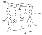
図1は本発明のバニシング装置及びそれを用いたバニシング方法の加工対象物である蒸気タービンのタービン翼を部分的に示す斜視図、図2は図1の符号Aで示す蒸気タービンのタービン翼とロータディスクとの連結部分を拡大した斜視図である。
Embodiments of a burnishing device and a burnishing method using the same according to the present invention will be described below with reference to the drawings.
First, the structure of the steam turbine which is a processing target of the burnishing apparatus of the present invention and the burnishing method using the burnishing apparatus will be described with reference to FIGS. 1 and 2.
FIG. 1 is a perspective view partially showing a turbine blade of a steam turbine which is a workpiece of a burnishing apparatus and a burnishing method using the burnishing device of the present invention, and FIG. 2 is a turbine blade of the steam turbine indicated by reference numeral A in FIG. It is the perspective view which expanded the connection part with a rotor disk.
図1において、タービン100は、ロータシャフト101と、ロータシャフト101の外周に取り付けられたロータディスク102と、ロータディスク102の外周に間隔を以って連結された複数のタービン翼103とを備えている。
In FIG. 1, a
図2に示すように、ロータディスク102とタービン翼103とを連結する連結部分104は、断面形状がクリスマスツリー状のロータディスク102のロータ植込み部105と、断面形状がクリスマスツリー状のタービン翼103の翼植込み部106とをかみ合わせた構造となっている。
As shown in FIG. 2, the connecting
タービン稼働時には、タービン翼103が蒸気を受けることにより連結されたロータシャフト101が回転し、この回転駆動力により発電機(図示せず)が発電する。このとき、回転するタービン翼103には遠心力が作用するが、噛み合わせ構造の連結部分104で遠心力を支持する。このため、ロータ植込み部105の溝底部107及び翼植込み部106の溝底部108に応力集中が生じて、局部的に高い応力が発生し、長期間の使用により、疲労き裂や応力腐食割れなどの損傷が発生するおそれがある。
When the turbine is operating, the
上記損傷を抑制する技術としては、表面に圧縮の残留応力層を形成させることにより、き裂の発生、進展を抑制するバニシングが有効である。バニシングは、形成される圧縮残留応力層が深いこと、加工後の表面粗さが滑らかであること、加工費用が比較的低コストであることなどの利点がある。 As a technique for suppressing the damage, burnishing which suppresses the generation and propagation of cracks by forming a compressive residual stress layer on the surface is effective. Burnishing has advantages such as a deep compressive residual stress layer to be formed, a smooth surface roughness after processing, and a relatively low processing cost.
[第1の実施の形態]
次に、本発明のバニシング装置の第1の実施の形態を図3乃至図6を用いて説明する。
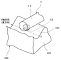
図3は本発明のバニシング装置の第1の実施の形態を示す概略構成図、図4は図3に示す本発明のバニシング装置の第1の実施の形態を構成するバニシングツールのローラを拡大して示す斜視図、図5は本発明のバニシング装置の第1の実施の形態におけるバニシングの過程を示す説明図、図6は本発明のバニシング装置の第1の実施の形態におけるバニシング実行時のビームのたわみとアームの変位との関係を示す説明図である。図3乃至図6において、図1及び図2に示す符号と同符合のものは、同一部分であるので、その詳細な説明は省略する。図3、図5、図6において、バニシングツールの挿入方向をX軸方向、ロータ植込み部の溝底部の溝方向をY軸方向、バニシングツールのロータ植込み部への押付け方向をZ軸方向とする。
[First Embodiment]
Next, a first embodiment of the burnishing device of the present invention will be described with reference to FIGS.
FIG. 3 is a schematic configuration diagram showing the first embodiment of the burnishing device of the present invention, and FIG. 4 is an enlarged view of the roller of the burnishing tool constituting the first embodiment of the burnishing device of the present invention shown in FIG. FIG. 5 is an explanatory view showing the burnishing process in the first embodiment of the burnishing device of the present invention, and FIG. 6 is the beam at the time of burnishing execution in the first embodiment of the burnishing device of the present invention. It is explanatory drawing which shows the relationship between deflection of an arm and the displacement of an arm. 3 to 6, the same reference numerals as those shown in FIGS. 1 and 2 are the same parts, and the detailed description thereof is omitted. 3, 5, and 6, the insertion direction of the burnishing tool is the X-axis direction, the groove direction of the groove bottom portion of the rotor implantation portion is the Y-axis direction, and the pressing direction of the burnishing tool to the rotor implantation portion is the Z-axis direction. .
本実施の形態においては、ロータディスク102のロータ植込み部105における狭隘な内面形状で高さ及び傾斜角が変化する加工面をバニシングする例を説明する。
図3において、バニシング装置は、加工対象物(ロータ植込み部105)に圧縮残留応力層を形成するバニシングツール1と、バニシングツール1をX、Y、Z軸方向に移動させるツール駆動装置2とを備えている。
In the present embodiment, an example will be described in which a machining surface having a narrow inner surface shape in the
In FIG. 3, the burnishing device includes a
バニシングツール1は、狭隘な内面形状のロータ植込み部105の溝底部107へのアクセスを考慮し、はりのたわみ反力を利用してツール先端部を加工面に押し付けるビーム方式を採用している。バニシングツール1は、ロータ植込み部105の狭隘部内に挿入可能なビーム11と、ビーム11の長手方向の一端側に設けた固定部12と、ビーム11の先端部の下側に設けられ、加工対象物の加工面を押圧する押圧部としてのローラ13とを有する。ローラ13は、図4に示すように、ビーム11の長手方向に平行な軸線方向(X軸方向)の回りに回転可能になっている。
The
ツール駆動装置2は、ベース部21と、ベース部21に対してY軸方向に移動可能に設けたY軸ステージ22と、Y軸ステージ22を移動させるY軸駆動装置23と、Y軸ステージ22に立設した支持部24と、支持部24にX軸方向に移動可能に取り付けたアーム25と、アーム25を支持部24に対してX軸方向に移動させるX軸駆動装置26と、アーム25を保持し、支持部24に対してZ軸方向に移動可能に設けたアーム保持部27と、アーム保持部27を支持部24に対してZ軸方向へ移動させるZ軸駆動装置28と、アーム25の先端側に設けたツールつかみ部29とを有している。
The
ツールつかみ部29には、チャッキング孔29aが設けられている。チャッキング孔29aには、バニシングツール1の固定部12を挿通してボルト締めすることにより、バニシングツール1が固定されている。
The
バニシングツール1は、X軸駆動装置26によりX軸方向に移動し、ロータ植込み部105間の間隙に挿入される。次に、Z軸駆動装置28によりZ軸方向に移動し、バニシングツール1のローラ13がロータ植込み部105の溝底部107に押し付けられる。ローラ13が溝底部107に押し付けられた状態で、図4に示すように、Y軸駆動装置23によりバニシングツール1がY軸方向に移動し、ローラ13が溝底部107を回転押圧しながら溝方向(Y軸方向)へ移動する(1ラインを加工する)。
The
ローラ13が溝底部107のY軸方向の一端から他端に向けて押圧しながら移動し終えたら、図5に示すように、X軸駆動装置26によりローラ13が所定のピッチpだけX軸方向に移動する。さらに、Z軸駆動装置28を駆動させてローラ13が溝底部107に再び押し付けられ、ローラ13はY軸方向の他端から一端に向けて押圧しながら移動する。以降、これを繰返すことにより溝底部107の全体のバニシングが完了する。
When the
このとき、ローラ13による加工面の法線方向の押付け力Fによって、接触部で局所的な塑性変形が生じ、圧縮残留応力が形成される。加工面の法線方向の押付け力Fとバニシングにより形成される圧縮残留応力の大きさとは相関がある。
At this time, the pressing force F in the normal direction of the processed surface by the
そこで、所定以上の圧縮残留応力を得るために、必要な許容押付け力Ftを予め定め、押付け力Fが許容押付け力Ftを下回らないように、ビーム11のたわみvはツール駆動装置2によって制御される。
Therefore, in order to obtain a compressive residual stress exceeding a predetermined value, a necessary allowable pressing force Ft is determined in advance, and the deflection v of the
上記のビーム11のたわみvを制御するための構成、作用を次に説明する。
図6に示すように、ビーム11のたわみvは、ツール駆動装置2のアーム25のZ軸方向(押付け方向)の変位uと次式(1)の関係にある。
Next, the configuration and operation for controlling the deflection v of the
As shown in FIG. 6, the deflection v of the
v=u−u0(x)… (1)
ここで、u0は、加工対象物(ロータ植込み部105)の加工面にローラ13が接触し始めるZ軸方向の基準変位であり、溝底部107のX軸方向の座標xの関数である。
v = u−u0 (x) (1)
Here, u0 is a reference displacement in the Z-axis direction at which the
このため、本実施の形態においては、ローラ13による押付け力Fを測定してビーム11のたわみvを制御する構成としている。
図3に戻り、ビーム11の固定部12近傍の上下面(ビーム11のバニシング実行時のせん断方向における両端部)には、ひずみセンサ14a、14bがそれぞれ設置されている。ひずみセンサ14a、14bは、コンピュータ3にそれぞれ接続されており、ビーム11のひずみ量をそれぞれ検出して、そのひずみ量に対応した検出信号をコンピュータ3にそれぞれ出力する。
For this reason, in this Embodiment, it is set as the structure which measures the pressing force F by the
Returning to FIG. 3,
コンピュータ3には、ツール駆動装置2のX軸駆動装置26、Y軸駆動装置23、Z軸駆動装置28を駆動し、アーム25の位置を制御するツール制御部4が接続されている。また、コンピュータ3には、バニシングの加工条件、バニシング実行時の測定データの表示、ツール駆動装置2のアーム25の変位uの制御値などのユーザからの各種指令を行うキーボード等の入力手段5と、バニシング実行時の測定データ等を表示するディスプレイ等の表示部6と、警報音を発する警報器7とが接続されている。
Connected to the computer 3 is a
コンピュータ3は、入出力部(I/O)31と、各種の特性図及び各種の設定値を予め記憶する記憶部32と、ひずみセンサ14a、14bからの検出値と特性図とに基づくローラ13による加工面の法線方向の押付け力Fの演算、演算した押付け力Fと設定値との比較判断、演算した押付け力Fと特性図と設定値とに基づくアーム25の押付け方向の変位uの補正値δuの演算を実行する演算部33とを備えている。
The computer 3 includes a
記憶部32には、演算部33が押付け力Fを演算するために、バニシング実行時の押付け力F、摩擦力、ビーム11のせん断力及びビーム11の軸力の釣り合いの関係を示す特性図が記憶されている(後述の図8参照)。また、演算した押付け力Fが所定以上の圧縮残留応力を形成できる押付け力であったか否かを比較判断するための設定値である許容押付け力Ftが記憶されている。さらに、演算部33がアーム25の変位uの補正量δuを演算するために、押付け力とビーム11のたわみの関係を示す特性図と、その特性図上において許容押付け力Ftに対応するビーム11の許容たわみvtとが記憶されている(後述の図9参照)。
The
また、記憶部32には、入力手段5から入力されたバニシングの加工条件、演算部33からの押付け力Fの演算結果等が記録される。
The
演算部33は、後述するように、ひずみセンサ14a、14bの検出信号を取り込み、ひずみセンサ14a、14bの検出信号と記憶部32に記憶した後述の図8に示す特性図とに基づき押付け力Fを演算し、その演算結果を記憶部32及び表示部6へ出力する。また、演算した押付け力Fが記憶部32に記憶した許容押付け力Ftを下回っているか否かを判断する。押付け力Fが許容押付け力Ftを下回ったと判断した場合には、警報指令信号を警報器7へ出力すると共に、押付け力Fが許容押付け力Ft以上となるようなアーム25の変位uの補正量δuを演算し、その演算結果を表示部6へ出力する。また、入力手段5から入力されたアーム25の変位uの補正量δuに基づいて補正量δu分移動させるための補正変位指令をツール制御部4へ出力する。
As will be described later, the
入出力部31は、ひずみセンサ14a、14bの検出信号及び入力手段5の指令信号が入力される。また、入出力部31は、演算部33からの押付け力Fの演算結果を表示部6へ出力し、演算部33からの警報指令信号を警報器7へ出力し、演算部33からのアーム25の変位uの補正量δuの演算結果を表示部6へ出力し、演算部33からの補正変位指令をツール制御部4へ出力する。
The input /
次に、演算部33がひずみセンサ14a、14bによる測定値からローラ13による押付け力Fを演算する具体的方法を図7及び図8を用いて説明する。
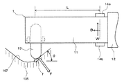
図7は本発明のバニシング装置の第1の実施の形態におけるバニシング実行時の傾斜した加工面に生じた押付け力及び摩擦力とビームに生じたせん断力及び軸力との関係を示す説明図、図8は本発明のバニシング装置の第1の実施の形態におけるバニシング実行時の押付け力、摩擦力、ビームのせん断力及びビームの軸力の釣り合いの関係を示す特性図である。図7及び図8において、図1乃至図6に示す符号と同符合のものは、同一部分であるので、その詳細な説明は省略する。
Next, a specific method in which the
FIG. 7 is an explanatory diagram showing the relationship between the pressing force and friction force generated on the inclined machining surface and the shearing force and axial force generated on the beam during burnishing in the first embodiment of the burnishing device of the present invention; FIG. 8 is a characteristic diagram showing the relationship among the pressing force, friction force, beam shear force, and beam axial force during burnishing in the first embodiment of the burnishing device of the present invention. 7 and 8, the same reference numerals as those shown in FIGS. 1 to 6 are the same parts, and detailed description thereof is omitted.
図7に示すビーム11のせん断力W、軸力Bは、ひずみセンサ14a、14bでそれぞれ測定されたひずみ量εa、εbから次式(2)、(3)で求められる。
The shearing force W and axial force B of the
W=(εb−εa)/2・E・Z/L …(2)
B=(εa+εb)/2・E・A …(3)
ここで、Eはビーム11のヤング率、Zはビーム11の断面係数、Aはビーム11の横断面積、Lはローラ13からひずみセンサ14a、14bまでの距離をそれぞれ示している。
W = (εb−εa) / 2 · E · Z / L (2)
B = (εa + εb) / 2 · E · A (3)
Here, E is the Young's modulus of the
ビーム11の先端部では、ローラ13による加工面の法線方向の押付け力F、加工面の接線方向の摩擦力f、ビーム11のせん断力W、ビーム11の軸力Bが釣り合っている。加工面の傾斜角をθ(絶対値)とすると、上下、左右の力の釣合いから、次式(4)〜(6)が成り立つ。
At the tip of the
Fcosθ+fsinθ=W …(4)
Fsinθ−fcosθ=B …(5)
f=min{μF、Ftanθ} …(6)
ここで、μは摩擦係数を示している。
Fcos θ + fsin θ = W (4)
Fsin θ−f cos θ = B (5)
f = min {μF, Ftanθ} (6)
Here, μ represents a friction coefficient.
加工面の傾斜角θが小さい場合、ビーム11のたわみvに応じて、ビーム11のせん断力Wが生じ、押付け力Fと摩擦力fとで釣り合い、ビーム11の軸力Bは0である。このとき、ローラ13が加工面上を滑らずに力が釣り合う状態であるから、μF>Ftanθであり、摩擦力fはFtanθとなる。
When the inclination angle θ of the processed surface is small, the shearing force W of the
一方、加工面の傾斜角θが大きい場合、押付け力Fと摩擦力f、ビーム11のせん断力Wだけでは、左右方向の釣り合いが取れず、ローラ13が加工面上を滑ろうとするため、ビーム11の軸力Bが発生する。このとき、ローラ13が加工面上を滑ろうとする状態であるため、μF<Ftanθであり、摩擦力fはμFとなる。
On the other hand, when the inclination angle θ of the processed surface is large, the pressing force F, the frictional force f, and the shearing force W of the
式(4)〜(6)の関係は、図8に示す特性図として示すことができる。図8は、縦軸がローラ13による押付け力とビーム11のせん断力との比F/W、横軸がビーム11の軸力とビーム11のせん断力との比B/Wを示している。図8中の実線Aは摩擦係数μが0.15の場合、破線Bは摩擦係数μが0.3の場合、点線Cは摩擦係数μが0.6の場合の特性曲線を示している。ここで、摩擦係数μは別途試験により測定した結果に応じて適切なものを選択する。
The relationship of Formula (4)-(6) can be shown as a characteristic view shown in FIG. In FIG. 8, the vertical axis indicates the ratio F / W between the pressing force of the
ひずみセンサ14a、14bの測定値から式(2)及び式(3)を用いて、せん断力W、軸力Bが求まるので、図8の特性曲線A、B、Cのうち摩擦係数μの試験結果に応じて選択した特性曲線を用いて、求めた軸力B及びせん断力Wで定まる横軸のB/Wの値から該当する縦軸のF/Wの値を求める。このF/Wの値から押付け力Fを求めることができる。
Since the shear force W and the axial force B are obtained from the measured values of the
ただし、ビーム11の軸力Bが0の場合には、縦軸のF/Wの値が一意に定まらないため、安全側に低めに見積もるものとして曲線ライン上の値(図8のプロット)を採用する。このときの縦軸のF/Wの値の誤差は、摩擦係数μが0.6の場合でも、最大14%である。
However, when the axial force B of the
このように、ロータ植込み部105のような加工面の傾斜角θが変化する加工対象物に対するバニシングにおいて、この傾斜角θを測定せずに押付け力Fを求めることが可能となる。
As described above, in the burnishing for the workpiece such as the
次に、演算部33がアーム25の押付け方向の変位uの補正量δuを演算する具体的方法を図9を用いて説明する。
図9は本発明のバニシング装置の第1の実施の形態におけるバニシング実行時の押付け力とビームのたわみの関係を示す特性図であり、縦軸はローラ13による押付け力F、横軸はビーム11のたわみvを示している。図中の特性曲線Aは、図8におけるF/W値が最小となる条件を選定した場合の押付け力とビームのたわみの関係を示す特性曲線である。
Next, a specific method in which the
FIG. 9 is a characteristic diagram showing the relationship between the pressing force and the deflection of the beam when the burnishing is performed in the first embodiment of the burnishing device of the present invention, where the vertical axis indicates the pressing force F by the
図中、許容押付け力Ft及びそれに対応した許容たわみvtは所定の圧縮残留応力を得るための設定値である。 In the figure, the allowable pressing force Ft and the allowable deflection vt corresponding thereto are set values for obtaining a predetermined compressive residual stress.
また、ロータ植込み部105の溝底部107の1ライン加工中に基準変位u0が最大変動量δu0変動したとしても、ローラ13による押付け力Fが許容押付け力Ft以上を維持できるように、開始押付け力Fs及びその開始押付け力Fsに対応する開始たわみvsが設定される。
Further, even if the reference displacement u0 fluctuates by the maximum fluctuation amount δu0 during one-line machining of the
この開始押付け力Fsは、1ライン加工するときに、アーム25の変位uの開始位置を定めるための基準値となる。
This starting pressing force Fs becomes a reference value for determining the starting position of the displacement u of the
1ライン加工中の基準変位u0の変動は、ロータ植込み部105のセッティング時のZ軸方向を軸とした回転ずれとロータ植込み部105の形状の寸法誤差により生じるものである。基準変位u0の最大変動量δu0は、例えば、初期値が0.5mmに設定され、ローラ13による押付け力Fが許容押付け力Ftを下回ってバニシングの再加工が実行された場合には、後述するアーム25の変位uの補正量δuに基づいて変更される。
The fluctuation of the reference displacement u0 during one-line machining is caused by a rotational deviation about the Z-axis direction when setting the
これらの許容押付け力Ft、許容たわみvt、開始押付け力Fs及び開始たわみvsは、この特性図と共に記憶部32に記憶されている。
These allowable pressing force Ft, allowable deflection vt, starting pressing force Fs, and starting deflection vs are stored in the
図9において、ロータ植込み部105の溝方向への1ライン加工中に測定された押付け力Fのうち、許容押付け力Ftを下回った最小の押付け力Fminから、最小たわみvminが求められる。この最小たわみvmin、開始たわみvs、基準変位u0の最大変動量δu0から、アーム25の変位uの補正量δuが次式(7)から求められる。
δu=(vs−vmin)−δu0 …(7)
このように、アーム25の変位uを補正量δu分だけ移動させると、図9から明らかのように、押付け力Fが許容押付け力Ft以上となる。
In FIG. 9, the minimum deflection vmin is obtained from the minimum pressing force Fmin that is less than the allowable pressing force Ft among the pressing forces F measured during one line processing in the groove direction of the
δu = (vs−vmin) −δu0 (7)
As described above, when the displacement u of the
なお、図9に示す特性曲線Aは、図8に示す特性図においてF/Wが最小となる条件を選定した場合の押付け力Fとたわみvの関係を示すものであり、Wはvと比例関係にあるからF/vも最小となる。そのため、この特性線Aから求められる押付け力Fは安全側に低くなるように配慮されている。 The characteristic curve A shown in FIG. 9 shows the relationship between the pressing force F and the deflection v when the condition that minimizes the F / W is selected in the characteristic diagram shown in FIG. 8, and W is proportional to v. Because of the relationship, F / v is also minimized. For this reason, the pressing force F obtained from the characteristic line A is considered to be low on the safe side.
次に、本発明のバニシング装置の第1の実施の形態を用いたバニシング方法を図3乃至図6、図8乃至図12を用いて説明する。
図10は本発明のバニシング装置の第1の実施の形態を用いたバニシング方法を示すフローチャート図、図11は本発明のバニシング装置の第1の実施の形態を構成するバニシングツールのチャッキングのずれを示す説明図、図12は本発明のバニシング装置の第1の実施の形態におけるバニシング実行時のビームのせん断力とビームのたわみとの関係を示す特性図である。図10乃至図12において、図1乃至図9に示す符号と同符合のものは、同一部分であるので、その詳細な説明は省略する。図10において、バニシングツールの挿入方向をX軸方向、ロータ植込み部の溝底部の溝方向をY軸方向、バニシングツールのロータ植込み部への押付け方向をZ軸方向とする。
Next, a burnishing method using the first embodiment of the burnishing apparatus of the present invention will be described with reference to FIGS. 3 to 6 and FIGS. 8 to 12.
FIG. 10 is a flowchart showing a burnishing method using the first embodiment of the burnishing apparatus of the present invention, and FIG. 11 is a chucking shift of the burnishing tool constituting the first embodiment of the burnishing apparatus of the present invention. FIG. 12 is a characteristic diagram showing the relationship between the beam shear force and the beam deflection at the time of burnishing in the first embodiment of the burnishing device of the present invention. In FIG. 10 to FIG. 12, the same reference numerals as those shown in FIG. 1 to FIG. In FIG. 10, the insertion direction of the burnishing tool is the X-axis direction, the groove direction of the groove bottom portion of the rotor implantation portion is the Y-axis direction, and the pressing direction of the burnishing tool to the rotor implantation portion is the Z-axis direction.
図10に示すように、バニシング加工をする前に、加工時に想定されるビーム11の最大せん断力Wmaxよりも大きなせん断力W0をビーム11に予めかける(ステップS1)。
As shown in FIG. 10, before burnishing, a shear force W0 larger than the maximum shear force Wmax of the
最大せん断力Wmaxとは、図3に示す溝底部107の溝方向(Y軸方向)の1ライン加工中に生じうる基準変位u0の最大変動量によりビーム11に生じるせん断力である。
The maximum shearing force Wmax is a shearing force generated in the
ビーム11にある大きさ以上のせん断力が加わると、図11に示すように、ツールつかみ部29のチャッキング孔29aに挿入された状態で固定されたバニシングツール1には、チャッキングのずれが生じる。図中、二点鎖線のバニシングツール1は、チャッキングのずれがない状態のバニシングツール1を、実線のバニシングツール1は、チャッキングのずれが生じた状態のバニシングツール1を示す。
When a shearing force greater than a certain size is applied to the
加工時に想定されるビーム11の最大せん断力Wmaxよりも大きなせん断力W0をビーム11に予めかけて、バニシングツール1のチャッキングのずれが生じた場合には、チャッキングのずれが生じた状態のバニシングツール1で加工することにより、加工中のチャッキングの更なるずれを抑制することができる。
When the chucking deviation of the
また、せん断力W0をビーム11に予めかけても、バニシングツール1のチャッキングのずれが生じない場合には、加工中にせん断力W0以上のせん断力がビーム11に加わらないので、バニシングツール1のチャッキングのずれは生じないと考えられる。
If the chucking of the
このため、加工中にバニシングツール1のチャッキングのずれが生じて押付け力Fが許容押付け力Ftを下回ることを抑制できる。
For this reason, it is possible to prevent the pressing force F from falling below the allowable pressing force Ft due to the occurrence of chucking deviation of the
次に、ビーム11の最大せん断力Wmaxの決定方法を図12を用いて説明する。
図12は本発明のバニシング装置の第1の実施の形態におけるバニシング実行時のビーム11のせん断力とビーム11のたわみとの関係を示す特性図であり、縦軸はビームのせん断力W、横軸はビーム11のたわみvを示している。図中の実線Aは、図8におけるF/Wが最小となるB/W=0時の条件を想定した場合のビームのせん断力とビームのたわみの関係を示す特性曲線である。
Next, a method for determining the maximum shear force Wmax of the
FIG. 12 is a characteristic diagram showing the relationship between the shearing force of the
1ライン加工中の基準変位u0の変動量を、例えば、±0.5mm以内と想定する。この場合、図12から、基準変位u0の変動量が±0.5mm以内において、たわみvが許容たわみvt以上となるように最大せん断力Wmaxが決定される。この場合、基準変位u0の最大変動量δu0は、初期値0.5mmに設定される。 A variation amount of the reference displacement u0 during one line processing is assumed to be within ± 0.5 mm, for example. In this case, from FIG. 12, the maximum shear force Wmax is determined so that the deflection v is equal to or greater than the allowable deflection vt when the fluctuation amount of the reference displacement u0 is within ± 0.5 mm. In this case, the maximum fluctuation amount δu0 of the reference displacement u0 is set to an initial value of 0.5 mm.
なお、図12に示す特性曲線Aは、図8におけるF/Wが最小となるB/W=0時の条件を想定した場合のビームのせん断力とビームのたわみの関係を示すものであるため、この特性線Aから求められるビームの最大せん断力Wmaxは安全側に高くなるように配慮されている。 The characteristic curve A shown in FIG. 12 shows the relationship between the beam shear force and the beam deflection when assuming the condition at B / W = 0 at which the F / W is minimum in FIG. The maximum shearing force Wmax of the beam obtained from the characteristic line A is taken into consideration so as to increase on the safe side.
図10に戻り、図3に示すツール駆動装置2のX軸駆動装置26を駆動させ、ビーム11をX軸方向へ移動させる。ビーム11の先端部をロータ植込み部105間に挿入し、ローラ13をロータ植込み部105の溝底部107のX軸方向の加工開始位置にセットする(ステップS2)。
Returning to FIG. 10, the
次に、Z軸駆動装置28を駆動させ、ビーム11をZ軸方向(押付け方向)へ移動させ、ローラ13を溝底部107に押圧させる(ステップS3)。ローラ13が溝底部107を押圧すると、図6に示すように、ビーム11がたわみ、ひずみセンサ14a、14bはそのひずみ量を検出し、そのひずみ量を演算部33に出力する。ひずみセンサ14a、14bは、ステップS3以降、ひずみ量を検出するとそのひずみ量を演算部33に常時出力する。
Next, the Z-
演算部33は、ひずみセンサ14a、14bで検出されたひずみ量を取り込み、そのひずみ量及び記憶部32に記憶された図8に示す特性図に基づいてローラ13による押付け力Fを演算し、押付け力Fの演算結果を表示部6に出力する(ステップS4)。これにより、押付け力Fが表示部6に表示される。
The
ローラ13による押付け力Fが所定の開始押付け力Fsとなるようにアーム25のZ軸方向の変位uをセットする(ステップS5)。開始押付け力Fsは、上述したように、基準変位u0が最大変動量δu0(初期値0.5mm)変動したとしても、ローラ13による押付け力Fが許容押付け力Ft以上を維持できるように設定されている。
The displacement u in the Z-axis direction of the
押付け力Fが開始押付け力Fsとなった状態のアーム25の変位uを保持した状態で、Y軸駆動装置23を駆動させ、図4に示すように、ローラ13が溝底部107のY軸方向(溝方向)の一端から他端まで1ライン加工する(ステップS6)。この加工中、ビーム11のたわみv及びローラ13による押付け力Fが基準変位u0の変動に伴い変化する。
The Y-
演算部33は、ひずみセンサ14a、14bで検出されたひずみ量を取り込み、このひずみ量及び記憶部32に記憶された図8に示す特性図に基づいて押付け力Fを演算し、押付け力Fの演算結果を記憶部32及び表示部6へ出力する(ステップS7)。これにより、1ライン加工時の押付け力Fが記憶部32に記録され、表示部6に表示される。
The
次に、1ライン加工終了後に、演算部33は、記憶部32に記録された1ライン加工時の押付け力Fが記憶部32に予め記憶された許容押付け力Ftを下回っているか否かを判断する(ステップS8)。押付け力Fが許容押付け力Ftを下回っている場合には、ステップ9へ進み、それ以外の場合には、ステップS13へ進む。
Next, after the end of one line processing, the
ステップS8において、押付け力Fが許容押付け力Ftを下回った場合(YES)には、演算部33は、警報器7へ警報指令信号を出力する(ステップS9)。これによって、警報器7が警報音を発する。この警報音により、1ライン加工時の押付け力Fが許容押付け力Ftを下回ったことをユーザに報知することができる。
In step S8, when the pressing force F is less than the allowable pressing force Ft (YES), the
また、演算部33は、図9に示す特性図からアーム25の変位uの補正量δuを演算し、補正量δuの演算結果を表示部6に出力する(ステップS9)。これにより、アーム25の変位uの補正量δuが表示部6に表示される。
Further, the
具体的には、演算部33は、記憶部32に記録された1ライン加工時の押付け力Fのうち、許容押付け力Ftを下回った最小の押付け力Fminと、記憶部32に記憶されている押付け力とビームのたわみの関係を示す特性図、開始たわみvs及び基準変位u0の最大変動量δu0(初期値0.5mm)とに基づいて補正量δuを演算する(図9参照)。
Specifically, the
補正量δuを演算した後に、最大変動量δu0がδu0+δuに変更される。この最大変動量δu0の変更に応じて、図9に示す特性図中の開始たわみvs及び開始押付け力Fsが変更される。すなわち、開始たわみvs及び開始押付け力Fsは、最大変動量δu0がδu増加した分、大きくなる。 After calculating the correction amount δu, the maximum fluctuation amount δu0 is changed to δu0 + δu. In accordance with the change of the maximum fluctuation amount δu0, the start deflection vs and the start pressing force Fs in the characteristic diagram shown in FIG. 9 are changed. That is, the starting deflection vs and the starting pressing force Fs increase as the maximum fluctuation amount δu0 increases by δu.
次に、表示部6に表示された補正量δuを入力手段5からコンピュータ3に入力する(ステップS10)。
Next, the correction amount δu displayed on the
演算部33は、入力手段5からの補正量δuを取り込み、アーム25の変位uがu+δuになるようにツール駆動装置2を制御する(ステップS11)。具体的には、演算部33は、入力手段5から入力された補正量δuに基づいてアーム25の変位uを補正量δu分移動させるための補正変位指令をツール制御部4へ出力し、ツール制御部4を介してアーム25の変位uがu+δuとなるようにZ軸駆動装置28を駆動させる。
The
次に、アーム25の変位uをu+δuに保持した状態で、Y軸駆動装置23を駆動させ、ステップS6と逆方向に他端から一端まで同一ラインを再度加工する(ステップS12)。
Next, in a state where the displacement u of the
再びステップS7に戻り、演算部33は、ひずみセンサ14a、14bで検出されたひずみ量を取り込んで押付け力Fを演算し、押付け力Fの演算結果を記憶部32及び表示部6へ出力する(ステップS7)。これにより、1ライン再加工時の押付け力Fが記憶部32に記録され、表示部6に表示される。
Returning to step S7 again, the
次に、ステップS11の1ラインの再加工後に、演算部33は、記憶部32に記録された1ライン再加工時の押付け力Fが記憶部32に予め記憶された許容押付け力Ftを下回っているか否かを判断する(ステップS8)。
Next, after reprocessing one line in step S <b> 11, the
ステップS8において、押付け力Fが許容押付け力Ftを下回る部分がなかった場合(NO)には、X軸駆動装置26を駆動させ、図5に示すように、ローラ13を所定ピッチpだけX軸方向にずらし、加工方向を逆方向にセットする(ステップS13)。これは、次のラインの加工準備を行うものである。本実施の形態においては、Y軸方向への1ライン加工終了ごとにローラ13をピッチpだけX軸方向にずらし、Y軸の逆方向へ向けて加工する工程を実行して、溝底部107全体のバニシングの加工処理を実行する。
In step S8, when there is no portion where the pressing force F is less than the allowable pressing force Ft (NO), the
次に、ローラ13がX軸方向の加工終了位置に到達したか否かが判断される(ステップS14)。ローラ13が加工終了位置に到達していない場合(NO)には、ステップS3へ戻り、上述した手順を繰り返すことで次のラインの加工が行われる。一方、ローラ13が加工終了位置に到達した(YES)場合には、加工完了となる。
Next, it is determined whether or not the
なお、次のラインの加工の場合のステップS5における開始押付け力Fsは、2つの場合があり、前のラインの加工の場合のステップS8において、1度もYESと判断されずにNOと判断されて1ラインの加工が実行された場合(前のラインの再加工がなっかた場合)と、少なくとも1度はYESと判断されて1ラインの加工が実行された場合(前のラインの再加工が実行された場合)とで異なる。 There are two cases of the starting pressing force Fs in step S5 in the case of processing the next line, and in step S8 in the case of processing of the previous line, it is determined as NO without being determined as YES. 1 line processing has been executed (when the previous line has not been reprocessed), or at least once is determined to be YES and 1 line has been processed (reworking the previous line) Is different).
前のラインの再加工がなかった場合には、次のラインの加工の場合のステップS5における開始押付け力Fsは、前のラインの加工の場合のステップS5における開始押付け力Fsと同一のものである。 If there is no reworking of the previous line, the starting pressing force Fs in step S5 in the case of processing of the next line is the same as the starting pressing force Fs in step S5 in the case of processing of the previous line. is there.
一方、前のラインの再加工が実行された場合には、次のラインの加工の場合のステップS5における開始押付け力Fsは、前のラインの加工におけるステップ9で変更された開始押付け力Fsと同一のものである。
On the other hand, when the reworking of the previous line is executed, the start pressing force Fs in step S5 in the case of the next line processing is the start pressing force Fs changed in
上述したように、加工対象物における高さ及び傾斜角が変化する加工面に対して、傾斜角θを測定せずに、押付け力不足となる部位を残さずにバニシングが可能となった。 As described above, burnishing is possible without measuring the inclination angle θ and leaving a portion where the pressing force is insufficient with respect to the machining surface where the height and the inclination angle of the workpiece are changed.
なお、上述したステップS9〜S11において、演算部33が演算した補正量δuを表示部6に出力し、表示部6に出力された補正量δuを入力手段5からコンピュータ3に入力し、入力された補正量δuに基づいて演算部33が補正変位指令をツール制御部4へ出力してツール制御部4を介してアーム25の変位uを制御する例を示したが、演算部33が演算した補正量δuを入力手段5からコンピュータ3に入力することなしに、演算部33がその演算結果に基づいて補正変位指令をツール制御部4へ出力してツール制御部4を介してアーム25の変位uを制御することもできる。
In steps S9 to S11 described above, the correction amount δu calculated by the
また、上述の例では、ステップS1〜S3、S5、S6、S10、S12〜S14の作業は、手動操作としたが、コンピュータ制御で自動化することが可能である。 In the above example, the operations in steps S1 to S3, S5, S6, S10, and S12 to S14 are manual operations, but can be automated by computer control.
次に、本発明のバニシング装置の第1の実施の形態を構成する表示部に表示された加工記録の出力結果を図13を用いて説明する。
図13は、本発明のバニシング装置の第1の実施の形態におけるバニシング方法の加工記録を表示した表示部の表示画面図である。
Next, the output result of the processing record displayed on the display unit constituting the first embodiment of the burnishing device of the present invention will be described with reference to FIG.
FIG. 13 is a display screen view of the display unit displaying the processing record of the burnishing method in the first embodiment of the burnishing device of the present invention.
表示部6には、加工時のX軸方向、Y軸方向座標におけるローラ13による押付け力Fが押付け力Fの大きさに応じて色分けして表示される。このため、押付け力不足がないことを一目で確認することができる。
On the
また、各加工ライン毎に、Y軸方向の両端における基準変位u0及びたわみv、再加工数、加工方向、所定ピッチp、加工速度も表示される。このため、必要に応じて加工状況を詳細に調べることができる。 In addition, for each machining line, the reference displacement u0 and deflection v at both ends in the Y-axis direction, the number of reworking, the machining direction, the predetermined pitch p, and the machining speed are also displayed. For this reason, the processing status can be examined in detail as necessary.
上述したように、本発明のバニシング装置の第1の実施の形態及びそれを用いたバニシング方法によれば、バニシングツール1のひずみ量に基づいて、押圧部13における加工対象物105の加工面の法線方向の押付け力Fを演算し、この演算した押付け力Fにより押圧部13を加工面に押し付けるようにしたので、加工対象物105における高さ及び傾斜角が変化する加工面に対して、バニシングの加工処理を確実に実行することができる。この結果、加工対象物105の長寿命化を図ることができる。
As described above, according to the first embodiment of the burnishing device of the present invention and the burnishing method using the same, the processing surface of the
また、本実施の形態によれば、ひずみセンサ14a、14bで検出されたひずみ量により演算した押付け力Fに基づいてアーム25の変位uを制御するため、ロータ植込み部105の形状情報をツール駆動装置2に予め入力しておく必要がない。さらに、詳細な形状情報を把握していないような加工対象物であっても、加工可能となる。
In addition, according to the present embodiment, the shape information of the
さらに、本実施の形態によれば、ローラ13による傾斜角θが変化する加工面の法線方向の押付け力F、加工面の接線方向の摩擦力f、ビーム11のせん断力W、ビーム11の軸力Bの釣り合いの関係を、図8に示すように、押付け力F、ビーム11のせん断力W及びビーム11の軸力Bとの特性関係として演算するようにしたので、ローラ13による傾斜角θが変化する加工面の法線方向の押付け力Fを傾斜角θを測定せずに演算することができる。
Furthermore, according to the present embodiment, the pressing force F in the normal direction of the machining surface where the tilt angle θ changes by the
また、本実施の形態によれば、バニシングツール1は、はりのたわみ反力を利用してローラ13を押し付けるビーム方式であるので、ロータ植込み部105のような狭隘な内面形状を有する加工対象物に対して、バニシングの加工処理を確実に実行することができる。
In addition, according to the present embodiment, the
さらに、本実施の形態によれば、測定された押付け力Fを押付け力Fの大きさに応じて色分けして表示部6に表示するので、容易かつ必要に応じて詳細に、バニシングの品質管理が可能となる。
Furthermore, according to the present embodiment, the measured pressing force F is color-coded according to the magnitude of the pressing force F and displayed on the
[第2の実施の形態]
次に、本発明のバニシング装置の第2の実施の形態を図3、図8及び図14を用いて説明する。
図14は本発明のバニシング装置の第2の実施の形態におけるバニシング実行時の押付け力とビームのたわみの関係を示す特性図である。図14において、図1乃至図13に示す符号と同符合のものは、同一部分であるので、その詳細な説明は省略する。
[Second Embodiment]
Next, a second embodiment of the burnishing apparatus according to the present invention will be described with reference to FIGS.
FIG. 14 is a characteristic diagram showing the relationship between the pressing force and the deflection of the beam when performing the burnishing in the second embodiment of the burnishing device of the present invention. In FIG. 14, the same reference numerals as those shown in FIGS. 1 to 13 denote the same parts, and a detailed description thereof will be omitted.
本発明の本発明のバニシング装置の第2の実施の形態は、第1の実施の形態がアーム25の変位uを固定してバニシングを一度実行し、加工不良が発見された場合に、測定された押付け力Fに応じてアーム25の変位uを補正して再度バニシングを実行する構成に対して、加工中に測定されている押付け力Fに応じてアーム25の変位uを逐次補正する構成である点が異なる。
The second embodiment of the burnishing device of the present invention is measured when the first embodiment performs burnishing once with the displacement u of the
本実施の形態を構成するコンピュータ3は、入出力部(I/O)31と、各種の特性図及び各種の設定値を予め記憶する記憶部32と、ひずみセンサ14a、14bからの検出値と特性図とに基づくローラ13による加工面の法線方向の押付け力Fの演算、演算した押付け力Fと特性図と設定値とに基づくビーム11のたわみvのたわみ補正量δvの演算を実行する演算部33とを備えている(図3参照)。
The computer 3 constituting this embodiment includes an input / output unit (I / O) 31, a
記憶部32には、演算部33が押付け力Fを演算するために、バニシング実行時の押付け力、摩擦力、ビーム11のせん断力及びビーム11の軸力の釣り合いの関係を示す特性図が記憶されている(図8参照)。また、演算部33がビーム11のたわみvのたわみ補正量δvを演算するために、押付け力とビーム11のたわみの関係を示す特性図と、許容押付け力Ft及びその特性図上において許容押付け力Ftに対応するビーム11の許容たわみvtと、ローラ13による押付け力Fを許容押付け力Ft以上に維持するためにその特性図上から設定された目標押付け力Fm及びその目標押付け力Fmに対応するたわみvの制御目標値vmとが記憶されている(後述の図14参照)。
The
演算部33は、ひずみセンサ14a、14bの検出信号を取り込み、ひずみセンサ14a、14bの検出信号と記憶部32に記憶した図8に示す特性図とに基づきローラ13による押付け力Fを演算し、その演算結果を記憶部32及び表示部6へ出力する。また、後述するように、演算した押付け力Fと記憶部32に記憶した目標押付け力Fmとに基づき、押付け力Fが目標押付け力Fmとなるようなビーム11のたわみvのたわみ補正量δvを逐次演算し、アーム25の変位uをたわみ補正量δv分移動させるための補正変位指令をツール制御部4へ逐次出力する。
The
次に、加工中にアーム25の変位uを逐次補正するための補正量を演算する具体的方法を図14を用いて説明する。
図14は本発明のバニシング装置の第2の実施の形態におけるバニシング実行時の押付け力とビームのたわみの関係を示す特性図であり、縦軸はローラ13による押付け力F、横軸はビーム11のたわみvを示している。図中の実線Aは、図8におけるF/W値が最小となる条件を選定した場合の押付け力とビームのたわみの関係を示す特性曲線である。
Next, a specific method for calculating a correction amount for sequentially correcting the displacement u of the
FIG. 14 is a characteristic diagram showing the relationship between the pressing force and the deflection of the beam when burnishing is performed in the second embodiment of the burnishing device of the present invention. The vertical axis indicates the pressing force F by the
図中、許容押付け力Ft及びそれに対応した許容たわみvは所定の圧縮残留応力を得るための設定値である。 In the figure, the allowable pressing force Ft and the allowable deflection v corresponding thereto are set values for obtaining a predetermined compressive residual stress.
また、ビーム11のたわみvを制御する際にたわみvの目標値からの最大のずれ分をδvmaxと想定した場合に、ローラ13による押付け力Fが許容押付け力Ft以上を維持できるように、目標押付け力Fm及びその目標押付け力Fmに対応するたわみvの制御目標値vmが設定されている。
Further, when the deflection v of the
これらの許容押付け力Ft、許容たわみvt、目標押付け力Fm及び制御目標値vmは、この特性図と共に記憶部32に記憶されている。
These allowable pressing force Ft, allowable deflection vt, target pressing force Fm and control target value vm are stored in the
アーム25の変位uの補正量を演算するために、まず、ひずみセンサ14a、14bの検出信号と図8に示す特性図とに基づいて演算された押付け力Fから目標押付け力Fmを減じることにより差分δF(=F−Fm)が求められる。次に、図14において、差分δFに対応するビーム11のたわみvのたわみ補正量δvが求められる。このたわみ補正量δvがアーム25の変位uの補正量である。
In order to calculate the correction amount of the displacement u of the
図14から明らかのように、アーム25の変位uをたわみ補正量δv分だけ移動させるとビーム11のたわみvが制御目標値vmになる。
As is apparent from FIG. 14, when the displacement u of the
なお、図14に示す特性曲線Aは、図8に示す特性図においてF/Wが最小となる条件を選定した場合の押付け力Fとたわみvの関係を示すものであり、Wはvと比例関係にあるからF/vも最小となる。そのため、この特性線Aから求められる押付け力Fは安全側に低くなるように配慮されている。 The characteristic curve A shown in FIG. 14 shows the relationship between the pressing force F and the deflection v when the condition that minimizes the F / W is selected in the characteristic diagram shown in FIG. 8, and W is proportional to v. Because of the relationship, F / v is also minimized. For this reason, the pressing force F obtained from the characteristic line A is considered to be low on the safe side.
次に、本発明のバニシング装置の第2の実施の形態を用いたバニシング方法を図3、図8、図14乃至図16を用いて説明する。
図15は本発明のバニシング装置の第2の実施の形態におけるバニシング方法を示すフローチャート図、図16は本発明のバニシング装置の第2の実施の形態におけるバニシング実行時のビームのせん断力とビームのたわみの関係を示す特性図である。図15及び図16において、図1乃至図14に示す符号と同符合のものは、同一部分であるので、その詳細な説明は省略する。図15において、バニシングツールの挿入方向をX軸方向、ロータ植込み部の溝底部の溝方向をY軸方向、バニシングツールのロータ植込み部への押付け方向をZ軸方向とする。
Next, a burnishing method using the second embodiment of the burnishing apparatus of the present invention will be described with reference to FIGS. 3, 8, 14 to 16.
FIG. 15 is a flowchart showing the burnishing method in the second embodiment of the burnishing apparatus of the present invention, and FIG. 16 shows the shear force of the beam and the beam at the time of burnishing execution in the second embodiment of the burnishing apparatus of the present invention. It is a characteristic view which shows the relationship of a bending. In FIG. 15 and FIG. 16, the same reference numerals as those shown in FIG. 1 to FIG. In FIG. 15, the insertion direction of the burnishing tool is the X-axis direction, the groove direction of the groove bottom portion of the rotor implantation portion is the Y-axis direction, and the pressing direction of the burnishing tool to the rotor implantation portion is the Z-axis direction.
図15に示すように、バニシング加工をする前に、加工時に想定されるビーム11の最大せん断力Wmaxよりも大きなせん断力W0をビーム11に予めかける(ステップS21)。
As shown in FIG. 15, before burnishing, a shear force W0 larger than the maximum shear force Wmax of the
ここで、ビーム11の最大せん断力Wmaxの決定方法を図16を用いて説明する。
図16は本発明のバニシング装置の第2の実施の形態におけるバニシング実行時のビームのせん断力とビームのたわみとの関係を示す特性図であり、縦軸はビームのせん断力W、横軸はビーム11のたわみvを示している。図中の実線Aは、図8におけるF/Wが最小となるB/W=0時の条件を想定した場合のビームのせん断力とビームのたわみの関係を示す特性曲線である。
Here, a method of determining the maximum shearing force Wmax of the
FIG. 16 is a characteristic diagram showing the relationship between beam shear force and beam deflection during burnishing in the second embodiment of the burnishing device of the present invention. The vertical axis represents the beam shear force W, and the horizontal axis represents the beam shear force. A deflection v of the
最大せん断力Wmaxは、ビーム11のたわみvが上述した制御目標値vmに対して最大δvmax分だけずれると想定したときに、ビーム11に生じるせん断力として決定される。
The maximum shearing force Wmax is determined as a shearing force generated in the
なお、図16に示す特性曲線Aは、図8におけるF/Wが最小となるB/W=0時の条件を想定した場合のビームのせん断力とビームのたわみの関係を示すものであるため、この特性曲線Aから求められるビームの最大せん断力Wmaxは安全側に高くなるように配慮されている。 Note that the characteristic curve A shown in FIG. 16 shows the relationship between the beam shear force and the beam deflection when assuming the condition at B / W = 0 at which the F / W is minimum in FIG. The maximum shearing force Wmax of the beam obtained from this characteristic curve A is considered to be higher on the safe side.
図15に戻り、第1の実施の形態と同様に、図3に示すビーム11をX軸方向へ移動させ、ビーム11の先端部をロータ植込み部105間に挿入し、ローラ13をロータ植込み部105の溝底部107のX軸方向の加工開始位置にセットする(ステップS22)。さらに、ビーム11をZ軸方向(押付け方向)へ移動させ、ローラ13を溝底部107に押圧させる(ステップS23)。ローラ13が溝底部107を押圧すると、ビーム11がたわみ、ひずみセンサ14a、14bがそのひずみ量を検出し、そのひずみ量を演算部33に出力する。
Returning to FIG. 15, similarly to the first embodiment, the
演算部33は、第1の実施の形態と同様に、ひずみセンサ14a、14bで検出されたひずみ量を取り込み、そのひずみ量及び記憶部32に記憶された図8に示す特性図に基づいて押付け力Fを演算し、押付け力Fの演算結果を表示部6に出力する(ステップS24)。これにより、押付け力Fが表示部6に表示される。
As in the first embodiment, the
ローラ13による押付け力Fが所定の目標押付け力Fmとなるようにアーム25のZ軸方向の変位uをセットする(ステップS25)。目標押付け力Fmは、上述したように、ビーム11のたわみvが制御目標値vmから最大δvmax分ずれた場合においても、ローラ13による押付け力Fが許容押付け力Ft以上を維持できるように設定されている。
The displacement u in the Z-axis direction of the
ローラ13を溝底部107のY軸方向(溝方向)に移動させ、加工する(ステップS26)。この加工中、ビーム11のたわみv及びローラ13による押付け力Fが基準変位u0の変動に伴い変化する。
The
演算部33は、第1の実施の形態と同様に、ひずみセンサ14a、14bで検出されたひずみ量を取り込み、このひずみ量及び記憶部32に記憶された図8に示す特性図に基づいて押付け力Fを演算し、押付け力Fの演算結果を記憶部32及び表示部6へ出力する(ステップS27)。これにより、押付け力Fが記憶部32に記録され、表示部6に表示される。
As in the first embodiment, the
演算部33は、この加工中に、押付け力Fと図14に示す特性図とからビーム11のたわみvのたわみ補正量δvを演算する(ステップS28)。具体的には、演算部33は、演算した押付け力Fと記憶部32に記憶された目標押付け力Fmとの差分δF(=F−Fm)を演算し、この差分δFと記憶部32に記憶されたビームのたわみの関係を示す特性図とに基づいてビーム11のたわみvのたわみ補正量δvを演算する(図14参照)。
During this processing, the
補正量δvを演算した後、演算部33は、アーム25の変位uがu+δvになるようにツール駆動装置2を制御する(ステップS29)。具体的には、演算部33は、演算結果のたわみ補正量δvに基づいてアーム25の変位uをたわみ補正量δv分移動させるための補正変位指令をツール制御部4へ出力し、ツール制御部4を介してアーム25の変位uがu+δvとなるようにZ軸駆動装置28を駆動させる。
After calculating the correction amount δv, the
次に、ローラ13がY軸方向の加工端部に到達したか否かが判断される(ステップS30)。ローラ13がY軸方向の加工端部に到達していない場合には、ステップ27へ戻り、それ以外の場合には、ステップS31へ進む。
Next, it is determined whether or not the
ステップS30において、ローラ13がY軸方向の加工端部に到達していない場合(NO)には、ステップS27へ戻り上述した手順を繰り返すことで、Y軸方向への加工がY軸方向の加工端部に到達するまで継続される。
In step S30, when the
このように、演算部33は、1ライン加工中に、ひずみセンサ14a、14bで検出されたひずみ量に基づいて押付け力Fを逐次演算し、押付け力Fの演算結果に基づいてビーム11のたわみvのたわみ補正量δvを演算し、たわみ補正量δvに基づいてアーム25の変位uをu+δvとなるよう逐次制御する。これにより、アーム25の変位uは、ローラ13による押付け力Fが目標押付け力Fmに保つように逐次補正される。すなわち、押付け力Fを目標押付け力Fmに保つようにフィードバック制御が行われた状態でY軸方向の加工が進行する。
In this way, the
一方、ステップS30において、ローラ13がY軸方向の加工端部に到達したら(YES)、ローラ13を所定ピッチpだけX軸方向にずらし、加工方向を逆方向にセットする(ステップS31)。これは、次のラインの加工準備を行うものである。本実施の形態においては、Y軸方向への1ライン加工終了ごとにローラ13をピッチpだけX軸方向にずらし、Y軸の逆方向へ向けて加工する工程を実行して、溝底部107全体のバニシングの加工処理を実行する。
On the other hand, when the
次に、ローラ13がX軸方向の加工終了位置に到達したか否かが判断される(ステップS32)。ローラ13が加工終了位置に到達していない場合(NO)には、ステップS23に戻り、上述した手順を繰り返すことで次のラインの加工が行われる。一方、ローラ13が加工終了位置に到達した場合(YES)には、加工完了となる。
Next, it is determined whether or not the
なお、上述の例では、ステップS21〜S23、S25、S26、S31、S32の作業は、手動操作としたが、コンピュータ制御で自動化することが可能である。 In the above example, the operations in steps S21 to S23, S25, S26, S31, and S32 are manual operations, but can be automated by computer control.
上述したように、本発明のバニシング装置及びそれを用いたバニシング方法の第2の実施の形態によれば、前述した第1の実施の形態と同様の効果を得ることができる。 As described above, according to the second embodiment of the burnishing device and the burnishing method using the same according to the present invention, the same effects as those of the first embodiment described above can be obtained.
また、本実施の形態によれば、1ライン加工中にローラ13による押付け力Fを目標押付け力Fmに保つようにアーム25の変位uを逐次補正するため、ローラ13による押付け力Fが不足することによる再加工のステップが不要となり、加工時間を短縮することができる。さらに、ローラ13の加工対象物105への過度の押付けも同時に防止でき、加工による加工対象物105の損傷の発生も防ぐことができる。
Further, according to the present embodiment, the displacement u of the
[第3の実施の形態]
次に、本発明のバニシング装置の第3の実施の形態を図17乃至図19を用いて説明する。
図17は本発明のバニシング装置の第3の実施の形態を示すものであり、バニシング実行時の傾斜した加工面に生じた押付け力及び摩擦力と軸力シャフトに生じたせん断力及び軸力との関係を示す説明図、図18は本発明のバニシング装置の第3の実施の形態におけるタービン翼の翼植え込み部に対するバニシングを示す説明図、図19は本発明のバニシング装置の第3の実施の形態におけるバニシング実行時の押付け力、摩擦力、シャフトせん断力及びシャフト軸力の釣り合いの関係を示す特性図である。図17乃至図19において、図1乃至図16に示す符号と同符合のものは、同一部分であるので、その詳細な説明は省略する。
[Third Embodiment]
Next, a third embodiment of the burnishing device of the present invention will be described with reference to FIGS.
FIG. 17 shows a third embodiment of the burnishing device according to the present invention. The pressing force and friction force generated on the inclined machining surface during burnishing, the shearing force and axial force generated on the axial shaft, FIG. 18 is an explanatory view showing burnishing for the blade implantation portion of the turbine blade in the third embodiment of the burnishing device of the present invention, and FIG. 19 is a third embodiment of the burnishing device of the present invention. It is a characteristic view which shows the relationship of the pressing force at the time of burnishing execution in a form, a frictional force, the shaft shear force, and the balance of a shaft axial force. 17 to 19, the same reference numerals as those shown in FIGS. 1 to 16 denote the same parts, and a detailed description thereof will be omitted.
図17に示す本発明のバニシング装置の第3の実施の形態は、第1の実施の形態を構成するバニシングツール1がはりのたわみ反力を利用してツール先端部を加工対象物に押し付ける構成であるのに対して、バニシングツール50は軸力を利用してツール先端部を加工対象物に押し付ける構成である点が異なる。
In the third embodiment of the burnishing device of the present invention shown in FIG. 17, the
バニシングツール50は、軸力シャフト51と、軸力シャフト51の長手方向の一端側に設けられた固定部52と、軸力シャフト51の長手方向の先端面に設けられ、加工対象物の加工面を押圧する押圧部としてのローラ53と、軸力シャフト51に内蔵された変位吸収ばね機構54とを有する。バニシングツール50は、軸力シャフト51の軸力でローラ53を加工面に押し付ける構成となっている。
The
ローラ53は、軸力シャフト51の長手方向に直交する軸線方向の回りに回転可能になっている。
The
変位吸収ばね機構54は、加工中の加工面の高さの変動を変位吸収ばね機構54内部のばね55で吸収し、軸力シャフト51による押付け力Fが過度に変動するのを防ぎ、押付け力Fを安定化させる機能を有する。
The displacement absorbing
軸力シャフト51の長手方向の中央部における上下面(軸力シャフト51のバニシング実行時のせん断方向における両端部)には、ひずみセンサ56a、56bがそれぞれ設置されている。
本実施の形態においては、図18に示すように、タービン翼103の翼植込み部106等の押付け方向と同一方向にバニシングツール50が挿入可能な加工対象物に対してバニシングが可能である。
In the present embodiment, as shown in FIG. 18, burnishing can be performed on a workpiece to which the
次に、ひずみセンサ56a、56bによる測定値からローラ53による押付け力Fを演算する具体的方法を図17及び図19を用いて説明する。
本実施の形態においては、第1の実施の形態を構成するビーム11のたわみ反力から、軸力シャフト51の軸力へと押付け方式が変わったため、ひずみセンサ56a、56bの測定値から押付け力Fを求める関係式が、第1の実施の形態と以下のように異なる。
Next, a specific method for calculating the pressing force F by the
In the present embodiment, since the pressing method is changed from the deflection reaction force of the
ひずみセンサ56a、56bそれぞれで測定されたひずみεa、εbから、シャフト軸力Bs、シャフトせん断力Wsが、次式(8)、(9)で求められる。
From the strains εa and εb measured by the
Bs=(εa+εb)/2・Es・As …(8)
Ws=(εa−εb)/2・Es・Zs/Ls …(9)
ここで、Esは軸力シャフト51のヤング率、Zsは軸力シャフト51の断面係数、Asは軸力シャフト51の横断面積、Lsはローラ53の先端からひずみセンサ56a、56bまでの距離をそれぞれ示している。
Bs = (εa + εb) / 2 · Es · As (8)
Ws = (εa−εb) / 2 · Es · Zs / Ls (9)
Here, Es is the Young's modulus of the
軸力シャフト51の先端部では、ローラ53による加工面の法線方向の押付け力F、加工面の接線方向の摩擦力f、シャフト軸力Bs、シャフトせん断力Wsが釣り合っている。加工面の傾斜角をθ(絶対値)とすると、上下、左右の釣合いから、次式(10)〜(12)が成り立つ。
At the tip of the
Fcosθ+fsinθ=Bs …(10)
Fsinθ−fcosθ=Ws …(11)
f=min{μF、Ftanθ} …(12)
ここで、μは摩擦係数を示している。
Fcos θ + fsin θ = Bs (10)
Fsin θ−f cos θ = Ws (11)
f = min {μF, Ftanθ} (12)
Here, μ represents a friction coefficient.
加工面の傾斜角θが小さい場合、押付け力Fと摩擦力fとで上下方向の力成分が釣り合い、シャフトせん断力Wsは0である。このとき、ローラ53が加工面上を滑らず、力が釣り合う状態であるから、μF>Ftanθであり、摩擦力fはFtanθとなる。
When the inclination angle θ of the processed surface is small, the force component in the vertical direction is balanced between the pressing force F and the frictional force f, and the shaft shearing force Ws is zero. At this time, since the
一方、加工面の傾斜角θが大きい場合、押付け力Fと摩擦力fとで上下方向の力の釣合いが取れず、ローラ53が加工面上を滑ろうとするため、シャフトせん断力Wsが発生する。このとき、ローラ53が加工面上を滑ろうとする状態であるため、μF<Ftanθであり、摩擦力fはμFとなる。
On the other hand, when the inclination angle θ of the processed surface is large, the pressing force F and the frictional force f cannot balance the vertical force, and the
式(10)乃至(12)の関係は、図19に示す特性図として示すことができる。図19は、縦軸がローラ53による押付け力とシャフト軸力との比F/Bs、横軸がシャフトせん断力とシャフト軸力との比Ws/Bsを示している。図19中の実線Aは摩擦係数μが0.15の場合、破線Bは摩擦係数μが0.3の場合、点線Cは摩擦係数μが0.6の場合の特性曲線を示している。ここで、摩擦係数μは別途試験により測定した結果に応じて適切なものを選択する。
The relationships of Expressions (10) to (12) can be shown as a characteristic diagram shown in FIG. In FIG. 19, the vertical axis represents the ratio F / Bs between the pressing force by the
ひずみセンサ56a、56bの測定値から、式(8)及び式(9)を用いて、シャフト軸力Bs及びシャフトせん断力Wsが求まるので、図8の特性曲線A、B、Cのうち図19に示す特性図のうち摩擦係数μの試験結果に応じて選択した特性図を用いて、求めたシャフト軸力Bs及びシャフトせん断力Wsで定まる横軸のWs/Bsの値から該当する縦軸のF/Bsの値を求める。このF/Bsの値から押付け力Fを求めることができる。
Since the shaft axial force Bs and the shaft shearing force Ws are obtained from the measured values of the
ただし、シャフトせん断力Wsが0の場合には、縦軸のF/Bsの値が一意に定まらないため、安全側に低めに見積もるものとして曲線ライン上の値(図19のプロット)を採用する。このときの縦軸のF/Bsの値の誤差は、摩擦係数μが0.6の場合でも、最大14%である。 However, when the shaft shearing force Ws is 0, the value of F / Bs on the vertical axis is not uniquely determined. Therefore, the value on the curve line (plot in FIG. 19) is adopted as a low estimate on the safe side. . The error in the value of F / Bs on the vertical axis at this time is 14% at maximum even when the friction coefficient μ is 0.6.
本実施の形態においては、翼植込み部106等の加工面の傾斜角θが変化する加工対象物に対するバニシングにおいて、この傾斜角θを予め測定せずに押付け力Fを求めることが可能となる。
In the present embodiment, it is possible to obtain the pressing force F without previously measuring the inclination angle θ in the burnishing for the object to be processed in which the inclination angle θ of the machining surface such as the
本実施の形態のバニシング方法の手順については、第1及び第2の実施の形態を用いたバニシング方法を流用することができる。この場合、本実施の形態は、第1及び第2の実施の形態がはりのたわみ反力を利用して押し付ける構成であるのに対して、軸力シャフト51の軸力を利用して押し付ける構成であるため、バニシングツールの押付け方向の変化に対応して、ビーム11のせん断力Wをシャフト軸力Bsに置き換えればよい。
For the procedure of the burnishing method of the present embodiment, the burnishing method using the first and second embodiments can be used. In this case, the present embodiment is configured to press using the axial force of the
上述したように、本発明のバニシング装置の第3の実施の形態によれば、軸力シャフト51の軸力による押付け方式を採用しているので、タービン翼103の翼植込み部106等の押付け方向と同一方向にバニシングツールが挿入可能な加工対象物における高さ及び傾斜角が変化する加工面に対して、バニシングの加工処理を確実に実行することができる。
As described above, according to the third embodiment of the burnishing device of the present invention, since the pressing method using the axial force of the
[その他]
なお、第1の実施の形態においては、加工対象物としてロータディスク102の植込み部105を例に示したが、タービン翼103の翼植込み部106にも適用することができる。
[Others]
In the first embodiment, the implanted
また、第1の実施の形態乃至第3の実施の形態においては、ロータディスク102の植込み部105とタービン翼103の翼植込み部106を例に示したが、加工面の高さ及び傾斜角が変化する加工対象物に適用することができる。例えば、自動車部品のベアリングハウジングのようなコーナR部を含む機器の強度改善を意図した加工などにも有効である。
In the first to third embodiments, the implanted
なお、第1の実施の形態乃至第3の実施の形態においては、押圧部としてローラを例に示したが、押圧部は加工対象物に対して圧縮残留応力層を形成できればよく、例えば、ボールを用いることができる。 In the first to third embodiments, a roller is shown as an example of the pressing portion. However, the pressing portion only needs to be able to form a compressive residual stress layer on the workpiece, for example, a ball Can be used.
また、第1の実施の形態乃至第3の実施の形態におけるツール駆動装置2は、少なくともXYZ軸の3軸制御可能な構成であればよい。
In addition, the
なお、本発明は上述した実施の形態に限られるものではなく、様々な変形例が含まれる。上述した実施の形態は本発明をわかり易く説明するために詳細に説明したものであり、必ずしも説明した全ての構成を備えるものに限定されるものではない。例えば、ある実施形態の構成の一部を他の実施の形態の構成に置き換えることが可能であり、また、ある実施形態の構成に他の実施の形態の構成を加えることも可能である。また、各実施形態の構成の一部について、他の構成の追加、削除、置換をすることも可能である。 The present invention is not limited to the above-described embodiments, and includes various modifications. The above-described embodiments have been described in detail for easy understanding of the present invention, and are not necessarily limited to those having all the configurations described. For example, part of the configuration of one embodiment can be replaced with the configuration of another embodiment, and the configuration of another embodiment can be added to the configuration of one embodiment. Moreover, it is also possible to add, delete, or replace another configuration for a part of the configuration of each embodiment.
また、上記の各構成、機能、処理部、処理手段等は、それらの一部または全部を、例えば集積回路で設計することによりハードウェアで実現してもよい。また、上記の各構成、機能等は、プロセッサがそれぞれの機能を実現するプログラムを解釈し、実行することによりソフトウェアで実現してもよい。各機能を実現するプログラム、テーブル、ファイル等の情報は、記憶部やハードディスク、SSD(Solid State Drive)等の記録装置、または、ICカード、SDカード、DVD等の記録媒体に置くことができる。 Each of the above-described configurations, functions, processing units, processing means, and the like may be realized by hardware by designing a part or all of them with, for example, an integrated circuit. Each of the above-described configurations, functions, and the like may be realized by software by interpreting and executing a program that realizes each function by the processor. Information such as programs, tables, and files that realize each function can be stored in a storage device, a hard disk, a recording device such as an SSD (Solid State Drive), or a recording medium such as an IC card, an SD card, or a DVD.
なお、制御線や情報線は説明上必要と考えられるものを示しており、製品上必ずしも全ての制御線や情報線を示しているとは限らない。実際には、殆ど全ての構成が相互に接続されていると考えてもよい。 Note that the control lines and information lines are those that are considered necessary for the explanation, and not all control lines and information lines on the product are necessarily shown. Actually, it may be considered that almost all the components are connected to each other.
1 バニシングツール
2 ツール駆動装置
3 コンピュータ
11 ビーム
13 ローラ(押圧部)
14a、14b ひずみセンサ
32 記憶部
33 演算部
50 バニシングツール
51 軸力シャフト
53 ローラ(押圧部)
56a、56b ひずみセンサ
105 ロータ植込み部(加工対象物)
106 翼植込み部(加工対象物)
107 溝底部
108 溝底部
DESCRIPTION OF
14a,
56a,
106 Wing implantation part (object to be processed)
107
Claims (4)
前記バニシングツールを移動させるツール駆動装置と、
前記バニシングツールのひずみ量を検出するひずみセンサと、
前記ひずみセンサが検出したひずみ量に基づいて前記押圧部による前記加工対象物の加工面の法線方向の押付け力を演算し、前記演算した押付け力と予め記憶した押付け力に基づいて前記ツール駆動装置の押付け方向の変位の補正量を演算し、その補正量をツール駆動装置に出力するコンピュータとを備え、
前記コンピュータは、
バニシング実行時の前記押圧部による前記押付け力,前記加工対象物の加工面の接線方向の摩擦力,前記バニシングツールのせん断力及び前記バニシングツールの軸力の釣り合いの関係を示す特性図と、所定の圧縮残留応力を形成可能な許容押付け力と、前記押圧部による前記押付け力と前記バニシングツールのたわみの関係を示す特性図とが予め記憶された記憶部と、
前記ひずみ量と前記釣り合いの関係を示す特性図とに基づいて前記押付け力を演算し、前記演算した押付け力と前記許容押付け力とを比較し、前記演算した押付け力が前記許容押付け力を下回った場合に、前記押圧部による前記押付け力と前記バニシングツールのたわみの関係を示す前記特性図と,前記許容押付け力を下回った最小の前記押付け力とに基づいて前記補正量を演算し、前記補正量をツール駆動装置に出力する演算部とを備えた
ことを特徴とするバニシング装置。 A burnishing tool having a pressing portion for rotating and pressing a processing surface whose height and inclination angle in a processing object change;
A tool drive for moving the burnishing tool;
A strain sensor for detecting a strain amount of the burnishing tool;
Based on the strain amount detected by the strain sensor, the pressing force in the normal direction of the processed surface of the workpiece is calculated by the pressing portion, and the tool driving is performed based on the calculated pressing force and the previously stored pressing force. A computer that calculates a correction amount of displacement in the pressing direction of the apparatus and outputs the correction amount to the tool driving device;
The computer
A characteristic diagram showing a relationship among the pressing force by the pressing portion when performing burnishing, the frictional force in the tangential direction of the processing surface of the workpiece, the shearing force of the burnishing tool, and the axial force of the burnishing tool; A storage unit in which an allowable pressing force capable of forming a compressive residual stress, and a characteristic diagram showing a relationship between the pressing force by the pressing unit and a deflection of the burnishing tool are stored in advance,
The pressing force is calculated based on a characteristic diagram showing the relationship between the strain amount and the balance, the calculated pressing force is compared with the allowable pressing force, and the calculated pressing force is less than the allowable pressing force. The correction amount is calculated based on the characteristic diagram showing the relationship between the pressing force by the pressing portion and the deflection of the burnishing tool, and the minimum pressing force below the allowable pressing force, A burnishing device comprising: an arithmetic unit that outputs a correction amount to a tool driving device.
前記バニシングツールを移動させるツール駆動装置と、
前記バニシングツールのひずみ量を検出するひずみセンサと、
前記ひずみセンサが検出したひずみ量に基づいて前記押圧部による前記加工対象物の加工面の法線方向の押付け力を演算し、前記演算した押付け力と予め記憶した押付け力に基づいて前記ツール駆動装置の押付け方向の変位の補正量を演算し、その補正量をツール駆動装置に出力するコンピュータとを備え、
前記コンピュータは、
バニシング実行時の前記押圧部による前記押付け力,前記加工対象物の加工面の接線方向の摩擦力,前記バニシングツールのせん断力及び前記バニシングツールの軸力の釣り合いの関係を示す特性図と、所定の圧縮残留応力を形成可能な許容押付け力と、前記押圧部による前記押付け力と前記バニシングツールのたわみの関係を示す特性図と、前記押圧部による前記押付け力を前記許容押付け力以上に維持するための目標押付け力とが予め記憶された記憶部と、
前記ひずみ量と前記釣り合いの関係を示す特性図とに基づいて前記押付け力を演算し、前記押圧部による前記押付け力と前記バニシングツールのたわみの関係を示す前記特性図と,前記演算した押付け力と,前記目標押付け力とに基づいて前記補正量を演算し、前記補正量をツール駆動装置に出力する演算部とを備えた
ことを特徴とするバニシング装置。 A burnishing tool having a pressing portion for rotating and pressing a processing surface whose height and inclination angle in a processing object change;
A tool drive for moving the burnishing tool;
A strain sensor for detecting a strain amount of the burnishing tool;
Based on the strain amount detected by the strain sensor, the pressing force in the normal direction of the processed surface of the workpiece is calculated by the pressing portion, and the tool driving is performed based on the calculated pressing force and the previously stored pressing force. A computer that calculates a correction amount of displacement in the pressing direction of the apparatus and outputs the correction amount to the tool driving device;
The computer
A characteristic diagram showing a relationship among the pressing force by the pressing portion when performing burnishing, the frictional force in the tangential direction of the processing surface of the workpiece, the shearing force of the burnishing tool, and the axial force of the burnishing tool; The allowable pressing force capable of forming a compressive residual stress, a characteristic diagram showing the relationship between the pressing force by the pressing portion and the deflection of the burnishing tool, and maintaining the pressing force by the pressing portion to be higher than the allowable pressing force A storage unit in which a target pressing force is stored in advance,
The pressing force is calculated based on a characteristic diagram showing the relationship between the strain amount and the balance, the characteristic diagram showing the relationship between the pressing force by the pressing portion and the deflection of the burnishing tool, and the calculated pressing force. And a calculation unit that calculates the correction amount based on the target pressing force and outputs the correction amount to a tool driving device.
前記バニシングツールは、前記加工対象物の狭隘部内に挿入可能なビームと、前記ビームの先端側に設け、前記ビームの長手方向に平行な軸線方向の回りに回転可能な押圧部とを備えた
ことを特徴とするバニシング装置。 The burnishing device according to claim 1 or 2 ,
The burnishing tool includes a beam that can be inserted into a narrow portion of the workpiece, and a pressing portion that is provided on the distal end side of the beam and is rotatable about an axial direction parallel to the longitudinal direction of the beam. A burnishing device characterized by the above.
前記バニシングツールは、軸力シャフトと、前記軸力シャフトの先端側に設け、前記軸力シャフトの長手方向に直交する軸線方向の回りに回転可能な押圧部とを備えた
ことを特徴とするバニシング装置。 The burnishing device according to claim 1 or 2 ,
The burnishing tool includes an axial force shaft and a pressing portion that is provided on a distal end side of the axial force shaft and is rotatable about an axial direction orthogonal to a longitudinal direction of the axial force shaft. apparatus.
Priority Applications (4)
| Application Number | Priority Date | Filing Date | Title |
|---|---|---|---|
| JP2012276072A JP6012104B2 (en) | 2012-12-18 | 2012-12-18 | Burnishing apparatus and burnishing method using the same |
| EP13192812.9A EP2745986B1 (en) | 2012-12-18 | 2013-11-14 | Burnishing device and burnishing method using it |
| US14/079,906 US9511471B2 (en) | 2012-12-18 | 2013-11-14 | Burnishing device and burnishing method using it |
| CN201310574451.1A CN103862368B (en) | 2012-12-18 | 2013-11-15 | Burnishing device and use the finishing method of this burnishing device |
Applications Claiming Priority (1)
| Application Number | Priority Date | Filing Date | Title |
|---|---|---|---|
| JP2012276072A JP6012104B2 (en) | 2012-12-18 | 2012-12-18 | Burnishing apparatus and burnishing method using the same |
Publications (3)
| Publication Number | Publication Date |
|---|---|
| JP2014117784A JP2014117784A (en) | 2014-06-30 |
| JP2014117784A5 JP2014117784A5 (en) | 2015-09-17 |
| JP6012104B2 true JP6012104B2 (en) | 2016-10-25 |
Family
ID=49679307
Family Applications (1)
| Application Number | Title | Priority Date | Filing Date |
|---|---|---|---|
| JP2012276072A Active JP6012104B2 (en) | 2012-12-18 | 2012-12-18 | Burnishing apparatus and burnishing method using the same |
Country Status (4)
| Country | Link |
|---|---|
| US (1) | US9511471B2 (en) |
| EP (1) | EP2745986B1 (en) |
| JP (1) | JP6012104B2 (en) |
| CN (1) | CN103862368B (en) |
Families Citing this family (13)
| Publication number | Priority date | Publication date | Assignee | Title |
|---|---|---|---|---|
| MX335107B (en) * | 2010-07-16 | 2015-11-26 | Applied Nano Surfaces Sweden Ab | METHOD TO PROVIDE A LOW FRICTION SURFACE. |
| AT512783B1 (en) * | 2012-05-22 | 2013-11-15 | Bosch Gmbh Robert | Method for rolling a cylindrical component surface |
| US10384326B2 (en) | 2015-12-21 | 2019-08-20 | General Electric Company | Surface treatment of turbomachinery |
| US9879536B2 (en) | 2015-12-21 | 2018-01-30 | General Electric Company | Surface treatment of turbomachinery |
| DE102017110198A1 (en) * | 2017-05-11 | 2018-11-15 | Walter Maschinenbau Gmbh | Grinding and / or EDM machine and method for measuring and / or referencing the machine |
| US10610963B2 (en) * | 2017-05-17 | 2020-04-07 | General Electric Company | Surface treatment of turbomachinery |
| DE102017220664A1 (en) * | 2017-11-20 | 2019-05-23 | Robert Bosch Gmbh | Device for processing semi-finished products and method, in particular for controlling the device |
| JP2019198938A (en) * | 2018-05-18 | 2019-11-21 | 株式会社荏原製作所 | Method for detecting polished surface of polishing pad by using polishing head, and polishing device |
| WO2020231394A1 (en) * | 2019-05-10 | 2020-11-19 | Brinkman Products, Inc. | Burnishing devices adapted for use in smaller diameter pipes |
| US20220276635A1 (en) * | 2019-07-24 | 2022-09-01 | Citizen Watch Co., Ltd. | Machining device, control device for use in the same, and method for controlling the machining device |
| EP3933524A1 (en) * | 2020-07-02 | 2022-01-05 | Kistler Holding AG | Method and device to ascertain a quality of a product obtained by subtractive manufacturing |
| CN112247740A (en) * | 2020-09-25 | 2021-01-22 | 深圳市裕展精密科技有限公司 | Polishing device, polishing method, polishing assisting device, polishing assisting system and polishing assisting method |
| CN112247741B (en) * | 2020-09-25 | 2022-04-08 | 深圳市裕展精密科技有限公司 | Calibration system, calibration method and calibration device |
Family Cites Families (12)
| Publication number | Priority date | Publication date | Assignee | Title |
|---|---|---|---|---|
| DE8802635U1 (en) * | 1988-02-29 | 1988-05-11 | Wilhelm Hegenscheidt Gmbh, 5140 Erkelenz, De | |
| JPH1158201A (en) | 1997-08-26 | 1999-03-02 | Toshiba Corp | Curved surface polishing device and method by force control |
| JP3794297B2 (en) * | 2001-07-30 | 2006-07-05 | 日産自動車株式会社 | Burnishing device and burnishing method |
| JP3984602B2 (en) * | 2004-03-31 | 2007-10-03 | 株式会社スギノマシン | Roller burnishing tool body and roller burnishing tool |
| JP4302574B2 (en) * | 2004-04-23 | 2009-07-29 | オークマ株式会社 | Burnishing processing method and processing apparatus |
| JP2006123059A (en) | 2004-10-28 | 2006-05-18 | Mitsubishi Heavy Ind Ltd | Polishing device, polishing robot using the same, and polishing method |
| CN2900084Y (en) * | 2005-06-02 | 2007-05-16 | 张亚斌 | Double wheel polishing machine |
| JP5113422B2 (en) * | 2007-05-23 | 2013-01-09 | 富士精工株式会社 | Roller burnishing device with pressure detection device |
| JP2011106332A (en) | 2009-11-17 | 2011-06-02 | Fuji Electric Systems Co Ltd | Turbine blade and method of processing the same |
| JP5762721B2 (en) | 2010-11-04 | 2015-08-12 | 株式会社東芝 | Reactor control rod surface treatment equipment |
| JP5221635B2 (en) * | 2010-12-27 | 2013-06-26 | 株式会社スギノマシン | Dimple forming burnishing tool |
| CN102490115A (en) * | 2011-11-22 | 2012-06-13 | 山东理工大学 | Low-temperature polisher |
-
2012
- 2012-12-18 JP JP2012276072A patent/JP6012104B2/en active Active
-
2013
- 2013-11-14 US US14/079,906 patent/US9511471B2/en active Active
- 2013-11-14 EP EP13192812.9A patent/EP2745986B1/en active Active
- 2013-11-15 CN CN201310574451.1A patent/CN103862368B/en active Active
Also Published As
| Publication number | Publication date |
|---|---|
| US9511471B2 (en) | 2016-12-06 |
| CN103862368B (en) | 2016-09-14 |
| JP2014117784A (en) | 2014-06-30 |
| US20140165351A1 (en) | 2014-06-19 |
| EP2745986A1 (en) | 2014-06-25 |
| EP2745986B1 (en) | 2015-09-30 |
| CN103862368A (en) | 2014-06-18 |
Similar Documents
| Publication | Publication Date | Title |
|---|---|---|
| JP6012104B2 (en) | Burnishing apparatus and burnishing method using the same | |
| JP6164948B2 (en) | Robot apparatus and component manufacturing method | |
| JP6196093B2 (en) | Vibration analysis method for bearing device, vibration analysis device for bearing device, and state monitoring device for rolling bearing | |
| US10471593B2 (en) | Rotation driving apparatus, robot apparatus, control program, and article manufacturing method | |
| JP5793200B2 (en) | Machine tool cutting force detection device, cutting force detection method, machining abnormality detection method, and machining condition control system | |
| EP2669755B1 (en) | Machining error computation device, machining error computation method, machining control device and machining control method | |
| KR102045095B1 (en) | Systems and methods for substrate polishing end point detection using improved friction measurement | |
| US11550290B2 (en) | Numerical control device and control method | |
| JP6837771B2 (en) | Feed axis abnormality judgment method | |
| WO2018139236A1 (en) | Machining control system and motion guide device | |
| JP2010120150A (en) | Estimation method for thermal deformation compensation of machine tool | |
| JP2019181654A (en) | Installation form determination device, computer program for determination of installation form and recording medium | |
| JP2009178754A (en) | Control method of rolling mill | |
| JP6490368B2 (en) | Machine tool control device, machine tool control method, and program | |
| JP2012086341A (en) | Automatic assembling device, automatic assembling method, and program | |
| Dong et al. | Wear reduction through piezoelectrically-assisted ultrasonic lubrication | |
| JP7424759B2 (en) | Spindle abnormality detection device | |
| JP2018119840A (en) | Measurement device | |
| JP2010069540A (en) | Abnormality detection device for drilling, machine tool equipped with the abnormality detection device, abnormality detection method | |
| RU2410661C2 (en) | Method to control profile of connection zone between cylindrical part and relief surface of part of gas turbine engine | |
| JP7278803B2 (en) | Information processing method, information processing device, robot system, robot system control method, article manufacturing method using robot system, program, and recording medium | |
| JP7475615B2 (en) | Gap detection device and method for robot joints | |
| JP4196975B2 (en) | Crack detection method for drive mechanism | |
| JP4879225B2 (en) | Machine tool and displacement correction method in machine tool | |
| JP2007333442A (en) | Shape measurement method |
Legal Events
| Date | Code | Title | Description |
|---|---|---|---|
| A711 | Notification of change in applicant |
Free format text: JAPANESE INTERMEDIATE CODE: A712 Effective date: 20140828 |
|
| RD02 | Notification of acceptance of power of attorney |
Free format text: JAPANESE INTERMEDIATE CODE: A7422 Effective date: 20141003 |
|
| A521 | Request for written amendment filed |
Free format text: JAPANESE INTERMEDIATE CODE: A523 Effective date: 20150731 |
|
| A621 | Written request for application examination |
Free format text: JAPANESE INTERMEDIATE CODE: A621 Effective date: 20150731 |
|
| A977 | Report on retrieval |
Free format text: JAPANESE INTERMEDIATE CODE: A971007 Effective date: 20160428 |
|
| A131 | Notification of reasons for refusal |
Free format text: JAPANESE INTERMEDIATE CODE: A131 Effective date: 20160531 |
|
| A521 | Request for written amendment filed |
Free format text: JAPANESE INTERMEDIATE CODE: A523 Effective date: 20160729 |
|
| TRDD | Decision of grant or rejection written | ||
| A01 | Written decision to grant a patent or to grant a registration (utility model) |
Free format text: JAPANESE INTERMEDIATE CODE: A01 Effective date: 20160906 |
|
| A61 | First payment of annual fees (during grant procedure) |
Free format text: JAPANESE INTERMEDIATE CODE: A61 Effective date: 20160916 |
|
| R150 | Certificate of patent or registration of utility model |
Ref document number: 6012104 Country of ref document: JP Free format text: JAPANESE INTERMEDIATE CODE: R150 |
|
| R250 | Receipt of annual fees |
Free format text: JAPANESE INTERMEDIATE CODE: R250 |
|
| R250 | Receipt of annual fees |
Free format text: JAPANESE INTERMEDIATE CODE: R250 |
|
| S533 | Written request for registration of change of name |
Free format text: JAPANESE INTERMEDIATE CODE: R313533 |
|
| R350 | Written notification of registration of transfer |
Free format text: JAPANESE INTERMEDIATE CODE: R350 |
|
| R250 | Receipt of annual fees |
Free format text: JAPANESE INTERMEDIATE CODE: R250 |
|
| R250 | Receipt of annual fees |
Free format text: JAPANESE INTERMEDIATE CODE: R250 |
|
| R250 | Receipt of annual fees |
Free format text: JAPANESE INTERMEDIATE CODE: R250 |