EP2745986A1 - Burnishing device and burnishing method using it - Google Patents
Burnishing device and burnishing method using it Download PDFInfo
- Publication number
- EP2745986A1 EP2745986A1 EP13192812.9A EP13192812A EP2745986A1 EP 2745986 A1 EP2745986 A1 EP 2745986A1 EP 13192812 A EP13192812 A EP 13192812A EP 2745986 A1 EP2745986 A1 EP 2745986A1
- Authority
- EP
- European Patent Office
- Prior art keywords
- pressing force
- burnishing
- pressing
- force
- tool
- Prior art date
- Legal status (The legal status is an assumption and is not a legal conclusion. Google has not performed a legal analysis and makes no representation as to the accuracy of the status listed.)
- Granted
Links
- 238000000034 method Methods 0.000 title claims abstract description 55
- 238000003825 pressing Methods 0.000 claims abstract description 291
- 238000006073 displacement reaction Methods 0.000 claims abstract description 77
- 238000012545 processing Methods 0.000 claims abstract description 71
- 230000008859 change Effects 0.000 claims abstract description 16
- 238000010586 diagram Methods 0.000 claims description 71
- 238000010008 shearing Methods 0.000 claims description 67
- 238000003860 storage Methods 0.000 claims description 42
- 230000008569 process Effects 0.000 description 17
- 238000001514 detection method Methods 0.000 description 8
- 238000006243 chemical reaction Methods 0.000 description 5
- 230000006870 function Effects 0.000 description 5
- 230000007246 mechanism Effects 0.000 description 4
- 238000012958 reprocessing Methods 0.000 description 4
- 230000000694 effects Effects 0.000 description 3
- 239000003086 colorant Substances 0.000 description 2
- 238000005056 compaction Methods 0.000 description 2
- 238000012986 modification Methods 0.000 description 2
- 230000004048 modification Effects 0.000 description 2
- 241000191291 Abies alba Species 0.000 description 1
- 238000010521 absorption reaction Methods 0.000 description 1
- 230000007797 corrosion Effects 0.000 description 1
- 238000005260 corrosion Methods 0.000 description 1
- 238000005336 cracking Methods 0.000 description 1
- 230000007774 longterm Effects 0.000 description 1
- 239000007769 metal material Substances 0.000 description 1
- 230000009467 reduction Effects 0.000 description 1
- 238000005096 rolling process Methods 0.000 description 1
- 239000007787 solid Substances 0.000 description 1
- 230000000087 stabilizing effect Effects 0.000 description 1
Images


Classifications
-
- B—PERFORMING OPERATIONS; TRANSPORTING
- B24—GRINDING; POLISHING
- B24B—MACHINES, DEVICES, OR PROCESSES FOR GRINDING OR POLISHING; DRESSING OR CONDITIONING OF ABRADING SURFACES; FEEDING OF GRINDING, POLISHING, OR LAPPING AGENTS
- B24B39/00—Burnishing machines or devices, i.e. requiring pressure members for compacting the surface zone; Accessories therefor
- B24B39/003—Burnishing machines or devices, i.e. requiring pressure members for compacting the surface zone; Accessories therefor the working tool being composed of a plurality of working rolls or balls
-
- B—PERFORMING OPERATIONS; TRANSPORTING
- B23—MACHINE TOOLS; METAL-WORKING NOT OTHERWISE PROVIDED FOR
- B23P—METAL-WORKING NOT OTHERWISE PROVIDED FOR; COMBINED OPERATIONS; UNIVERSAL MACHINE TOOLS
- B23P9/00—Treating or finishing surfaces mechanically, with or without calibrating, primarily to resist wear or impact, e.g. smoothing or roughening turbine blades or bearings; Features of such surfaces not otherwise provided for, their treatment being unspecified
- B23P9/02—Treating or finishing by applying pressure, e.g. knurling
-
- B—PERFORMING OPERATIONS; TRANSPORTING
- B24—GRINDING; POLISHING
- B24B—MACHINES, DEVICES, OR PROCESSES FOR GRINDING OR POLISHING; DRESSING OR CONDITIONING OF ABRADING SURFACES; FEEDING OF GRINDING, POLISHING, OR LAPPING AGENTS
- B24B39/00—Burnishing machines or devices, i.e. requiring pressure members for compacting the surface zone; Accessories therefor
- B24B39/02—Burnishing machines or devices, i.e. requiring pressure members for compacting the surface zone; Accessories therefor designed for working internal surfaces of revolution
-
- G—PHYSICS
- G05—CONTROLLING; REGULATING
- G05B—CONTROL OR REGULATING SYSTEMS IN GENERAL; FUNCTIONAL ELEMENTS OF SUCH SYSTEMS; MONITORING OR TESTING ARRANGEMENTS FOR SUCH SYSTEMS OR ELEMENTS
- G05B19/00—Programme-control systems
- G05B19/02—Programme-control systems electric
- G05B19/18—Numerical control [NC], i.e. automatically operating machines, in particular machine tools, e.g. in a manufacturing environment, so as to execute positioning, movement or co-ordinated operations by means of programme data in numerical form
- G05B19/404—Numerical control [NC], i.e. automatically operating machines, in particular machine tools, e.g. in a manufacturing environment, so as to execute positioning, movement or co-ordinated operations by means of programme data in numerical form characterised by control arrangements for compensation, e.g. for backlash, overshoot, tool offset, tool wear, temperature, machine construction errors, load, inertia
-
- B—PERFORMING OPERATIONS; TRANSPORTING
- B23—MACHINE TOOLS; METAL-WORKING NOT OTHERWISE PROVIDED FOR
- B23Q—DETAILS, COMPONENTS, OR ACCESSORIES FOR MACHINE TOOLS, e.g. ARRANGEMENTS FOR COPYING OR CONTROLLING; MACHINE TOOLS IN GENERAL CHARACTERISED BY THE CONSTRUCTION OF PARTICULAR DETAILS OR COMPONENTS; COMBINATIONS OR ASSOCIATIONS OF METAL-WORKING MACHINES, NOT DIRECTED TO A PARTICULAR RESULT
- B23Q17/00—Arrangements for observing, indicating or measuring on machine tools
- B23Q17/22—Arrangements for observing, indicating or measuring on machine tools for indicating or measuring existing or desired position of tool or work
- B23Q17/2233—Arrangements for observing, indicating or measuring on machine tools for indicating or measuring existing or desired position of tool or work for adjusting the tool relative to the workpiece
-
- B—PERFORMING OPERATIONS; TRANSPORTING
- B24—GRINDING; POLISHING
- B24B—MACHINES, DEVICES, OR PROCESSES FOR GRINDING OR POLISHING; DRESSING OR CONDITIONING OF ABRADING SURFACES; FEEDING OF GRINDING, POLISHING, OR LAPPING AGENTS
- B24B39/00—Burnishing machines or devices, i.e. requiring pressure members for compacting the surface zone; Accessories therefor
-
- G—PHYSICS
- G05—CONTROLLING; REGULATING
- G05B—CONTROL OR REGULATING SYSTEMS IN GENERAL; FUNCTIONAL ELEMENTS OF SUCH SYSTEMS; MONITORING OR TESTING ARRANGEMENTS FOR SUCH SYSTEMS OR ELEMENTS
- G05B19/00—Programme-control systems
-
- Y—GENERAL TAGGING OF NEW TECHNOLOGICAL DEVELOPMENTS; GENERAL TAGGING OF CROSS-SECTIONAL TECHNOLOGIES SPANNING OVER SEVERAL SECTIONS OF THE IPC; TECHNICAL SUBJECTS COVERED BY FORMER USPC CROSS-REFERENCE ART COLLECTIONS [XRACs] AND DIGESTS
- Y10—TECHNICAL SUBJECTS COVERED BY FORMER USPC
- Y10T—TECHNICAL SUBJECTS COVERED BY FORMER US CLASSIFICATION
- Y10T29/00—Metal working
- Y10T29/47—Burnishing
Definitions
- the present invention relates to a burnishing device and a burnishing method using it.
- the burnishing tool described in Patent Document 1 is a roller burnishing tool that includes a cylindrical shank, a head, and a roller for compaction.
- the head is arranged in the shank through a pivot shaft and pivots by work pressing force.
- the burnishing tool further includes a biasing unit, a biasing force adjusting unit, and a biasing force converting unit.
- the biasing unit is arranged in the cylindrical shank and biases in a shank axis direction.
- the biasing force adjusting unit adjusts biasing force generated by the biasing unit.
- the biasing force converting unit transmits the biasing force to a head shaft and changes a direction of the biasing force to a direction in which the head shaft pivots.
- the burnishing tool controls the work pressing force to be generated upon rolling compaction.
- a part that connects turbine blades of a steam turbine or the like to a turbine rotor disk has a structure in which an attachment base located on the side of the turbine blades is engaged with an attachment base located on the side of the turbine rotor disk.
- the connection part balances centrifugal force applied to the turbine blades upon an operation of the turbine and thus needs to have sufficient fatigue resistance.
- Patent Document 1 describes the fact that an edge of the burnishing tool is pressed against an inner surface of a cylindrical object, a unit for measuring pressing force is not provided. If the invention described in Patent Document 1 is applied to the part that connects the turbine blades to the turbine rotor disk, there is a problem that compressive residual stress is not reliably formed on a processed part of an attachment base due to displacement of the set attachment base or an error of a dimension of the attachment base. Especially, for a portion (such as the attachment base) of which the height and inclination angle of a surface (to be processed) vary, an error between an input position of the portion and the actual position of the portion easily occurs. Thus, it is likely that the portion may not be sufficiently processed by the burnishing.
- the present invention was devised to solve the aforementioned problems, and an object of the invention is to provide a burnishing device and a burnishing method that enable burnishing to be reliably performed on a surface, which is included in an object to be processed and is to be processed by burnishing and has a change in height and inclination angle.
- a burnishing device including a burnishing tool having a pressing unit that rotationally presses a surface of an object to be processed, the surface having a change in height and inclination angle; a tool driving device configured to move the burnishing tool; a strain sensor configured to detect a strain amount of the burnishing tool; and/or a computer configured to calculate pressing force to be applied by the pressing unit in a normal direction of the surface of the object to be processed, the calculation being on the basis of the strain amount detected by the strain sensor, calculate a correction amount of displacement of the tool driving device in a pressing direction, the calculation being on the basis of the calculated pressing force and stored pressing force in advance, and/or output the correction amount to the tool driving device.
- the pressing force to be applied by the pressing unit in the normal direction of the surface of the object to be processed is calculated on the basis of the strain amount of the burnishing tool, the pressing unit presses the surface by the calculated pressing force, and the burnishing processing can be reliably performed on the surface, which is included in the object to be processed and has a change in height and inclination angle. As a result, the service life of the object to be processed can be increased.
- Fig. 1 is a perspective view partially illustrating turbine blades of the steam turbine to be processed using the burnishing method by the burnishing device.
- Fig. 2 is an enlarged perspective view of a part indicated by a symbol A in Fig. 1 , which shows a connection of turbine blades and a turbine rotor disk in the steam turbine.
- the turbine 100 includes a rotor shaft 101, the turbine rotor disk 102, and the plurality of turbine blades 103.
- the turbine rotor disk 102 is attached to an outer circumferential portion of the rotor shaft 101.
- the turbine blades 103 are connected to an outer circumferential portion of the turbine rotor disk 102 at intervals.
- the part 104 that connects the turbine rotor disk 102 to the turbine blades 103 has such a structure: rotor attachment bases 105 of the turbine rotor disk 102 are engaged with blade attachment bases 106 of the turbine blades 103, attachment bases 105 and 106 both having Christmas tree shape in cross section.
- the connected rotor shaft 101 is rotated by causing the turbine blades 103 to receive steam, and a generator (not illustrated) generates power by rotational driving force of the rotor shaft 101.
- a generator (not illustrated) generates power by rotational driving force of the rotor shaft 101.
- centrifugal force acts on the rotating turbine blades 103 and is supported by the connection part 104 having the engagement structure.
- stress is concentrated at groove bottom portions 107 of the rotor attachment bases 105 and groove bottom portions 108 of the blade attachment bases 106.
- generated locally high stress may cause damage such as a fatigue crack or stress corrosion cracking under long-term use.
- burnishing which suppresses the occurrence or progress of a crack or the like by forming a compressive residual stress layer on a surface.
- the burnishing has advantages that the formed compressive residual stress layer is deep, a processed surface is smooth, and the processing cost is low.
- Fig. 3 is an outline configuration diagram illustrating the burnishing device according to the first embodiment of the invention.
- Fig. 4 is an enlarged perspective view illustrating a roller of a burnishing tool that constitutes a part of the burnishing device (illustrated in Fig. 3 ) according to the first embodiment of the invention.
- Fig. 5 is a diagram describing a burnishing process to be performed by the burnishing device according to the first embodiment of the invention.
- Fig. 6 is a diagram illustrating the relationship between deflection of a beam and displacement of an arm upon the burnishing performed by the burnishing device according to the first embodiment of the invention. Reference numerals that are illustrated in Figs. 3 to 6 and the same as those illustrated in Figs.
- a direction in which the burnishing tool is inserted is X-direction
- a direction in which the groove bottom portions of the rotor attachment bases extend is Y-direction
- a direction in which the burnishing tool presses the rotor attachment base is Z-direction.
- the present embodiment describes an example in which a surface processed inside of the rotor attachment base 105 of the rotor disk is subjected to burnishing. Prior to burnishing, the surface processed is formed in a narrow inner surface shape and has a change in height and inclination angle.
- the burnishing device includes a burnishing tool 1 and a tool driving device 2.
- the burnishing tool 1 forms a compressive residual stress layer on an object (rotor attachment bases 105) to be processed.
- the tool driving device 2 moves the burnishing tool 1 in X-, Y-, and Z-directions.
- the burnishing tool 1 uses a beam scheme in consideration of access to the groove bottom portions 107 of the rotor attachment bases 105 having the narrow inner surface.
- deflection reaction force of a beam 11 is used to press an edge of the burnishing tool 1 against the surface to be processed.
- the burnishing tool 1 includes the beam 11, a fixing portion 12, and a roller 13.
- the beam 11 can be inserted in a narrow portion of the rotor attachment base 105.
- the fixing portion 12 is arranged at one edge of the beam 11 in a longitudinal direction of the beam 11.
- the roller 13 serves as a pressing unit that presses the surface (to be processed) of the object to be processed. As illustrated in Fig. 4 , the roller 13 is capable of rotating around an axial direction (X-direction) parallel to the longitudinal direction of the beam 11.
- the tool driving device 2 includes a base portion 21, a Y-axis stage 22, a Y-axis driving device 23, a holding portion 24, an arm 25, an X-axis driving device 26, an arm holding portion 27, a Z-axis driving device 28, and a tool gripping portion 29.
- the Y-axis stage 22 is capable of moving in Y-direction relative to the base portion 21.
- the Y-axis driving device 23 moves the Y-axis stage 22.
- the holding portion 24 stands on the Y-axis stage 22.
- the arm 25 is attached to the holding portion 24 and capable of moving in X-direction.
- the X-axis driving device 26 moves the arm 25 relative to the holding portion 24 in X-direction.
- the arm holding portion 27 holds the arm 25 and is capable of moving relative to the holding portion 24 in Z-direction.
- the Z-axis driving device 28 moves the arm holding portion 27 relative to the holding portion 24 in Z-direction.
- the tool gripping portion 29 is arranged at an edge of the arm 25.
- the tool gripping portion 29 has a chucking hole 29a.
- the burnishing tool 1 is fixed to the chucking hole 29a by inserting the fixing portion 12 of the burnishing tool 1 in the chucking hole 29a and bolting the fixing portion 12.
- the burnishing tool 1 is moved in X-direction by the X-axis driving device 26 and inserted in a gap between the rotor attachment bases 105.
- the burnishing tool 1 is moved in Z-direction by the Z-axis driving device 28 and the roller 13 of the burnishing tool 1 is pressed against the groove bottom portion 107 of the rotor attachment base 105.
- the burnishing tool 1 is moved in Y-direction by the Y-axis driving device 23 and the roller 13 is moved in a groove direction (Y-direction) while rotationally pressing the groove bottom portion 107 (or processing one line), as illustrated in Fig. 4 .
- the roller 13 finishes moving from one end to the other end of the groove bottom portion 107 in Y-direction while pressing the surface to be processed, the roller 13 is moved in X-direction by a predetermined pitch p by the X-axis driving device 26 as illustrated in Fig. 5 .
- the Z-axis driving device 28 is driven to cause the roller 13 to be pressed against the groove bottom portion 107 again and the roller 13 is moved from the other end to one end of the groove bottom portion 107 in Y-direction while pressing the groove bottom portion 107. By repeating this operation, the burnishing is completed on the overall groove bottom portion 107.
- Necessary allowable pressing force Ft is determined in advance to obtain predetermined compressive residual stress or higher, and deflection v of the beam 11 is controlled by the tool driving device 2 so that the pressing force F is not lower than the allowable pressing force Ft.
- the deflection v of the beam 11 is represented by the following Equation (1) using displacement u of the arm 25 of the tool driving device 2 in Z-direction (pressing direction).
- v u - u ⁇ 0 x
- u0 is standard displacement of the arm 25 in Z-direction when the roller 13 starts contacting the surface (to be processed) of the object (rotor attachment base 105) to be processed.
- u0 is a function of a coordinate x of the groove bottom portion 107 in X-direction.
- the pressing force F to be applied by the roller 13 is measured to control the deflection v of the beam 11.
- strain sensors 14a and 14b are arranged on upper and lower surfaces (both edges of the beam 11 in a shearing direction upon the burnishing) of the beam 11 in the vicinity of the fixing portion 12.
- the strain sensors 14a and 14b are connected to the computer 3.
- the strain sensors 14a and 14b detect the strain amounts of the beam 11 and output detection signals corresponding to the amounts of the strains to the computer 3.
- the computer 3 is connected to a tool controller 4 that drives the X-axis driving device 26, Y-axis driving device 23, and Z-axis driving device 28 of the tool driving device 2 and controls the position of the arm 25.
- the computer 3 is connected to an input unit 5, a display unit 6, and an alarm unit 7.
- the input unit 5 is a keyboard or the like and provides a command to display data measured upon the burnishing and provides a various commands (from a user) such as processing requirements for the burnishing and a control value of displacement u of the arm 25 of the tool driving device 2.
- the display unit 6 displays the data measured upon the burnishing and the like.
- the alarm unit 7 provides an alarm sound.
- the computer 3 includes an input/output (I/O) unit 31, a storage unit 32, and a calculator 33.
- the storage unit 32 stores various characteristic diagrams and various set values.
- the calculator 33 calculates, on the basis of the detection values received from the strain sensors 14a and 14b and the characteristic diagrams, the pressing force F to be applied by the roller 13 to the surface (to be processed) in the normal direction of the surface to be processed.
- the calculator 33 compares the calculated pressing force F with a set value and calculates a correction amount ⁇ u of the displacement u of the arm 25 in the pressing direction on the basis of the calculated pressing force F, the characteristic diagrams, and the set value.
- the storage unit 32 stores a characteristic diagram (refer to Fig. 8 described later) indicating relationships of balance between the pressing force F, friction force, shearing force of the beam 11, and axial force of the beam 11 upon the burnishing in order for the calculator 33 to calculate the pressing force F.
- the storage unit 32 stores the allowable pressing force Ft that is the set value to be used for the comparison with the calculated pressing force F and determination of whether the calculated pressing force F is equal to or larger than pressing force that enables predetermined compressive residual stress to be formed.
- the storage unit 32 stores a characteristic diagram indicating the relationship between the pressing force and the deflection of the beam 11 and stores allowable deflection vt (of the beam 11) corresponding to the allowable pressing force Ft on the characteristic diagram in order for the calculator 33 to calculate the correction amount ⁇ u of the displacement u of the arm 25 (refer to Fig. 9 described later).
- the storage unit 32 stores the processing requirements (for the burnishing) input from the input unit 5, the result of calculating the pressing force F by the calculator 33, and the like.
- the calculator 33 acquires the detection signals of the strain sensors 14a and 14b, calculates the pressing force F on the basis of the detection signals of the strain sensors 14a and 14b and the characteristic diagram (illustrated in Fig. 8 described later) stored in the storage unit 32, and outputs the result of the calculation to the storage unit 32 and the display unit 6. In addition, the calculator 33 determines whether or not the calculated pressing force F is lower than the allowable pressing force Ft stored in the storage unit 32.
- the calculator 33 determines that the calculated pressing force F is lower than the allowable pressing force Ft, the calculator 33 outputs an alarm command signal to the alarm unit 7, calculates the correction amount ⁇ u (of the displacement u of the arm 25) causing the pressing force F to be equal to or higher than the allowable pressing force Ft, and outputs the result of calculating the correction amount ⁇ u to the display unit 6. Furthermore, the calculator 33 outputs, to the tool controller 4, a correction displacement command to change the displacement u of the arm 25 by the correction amount ⁇ u on the basis of the correction amount ⁇ u (of the displacement u of the arm 25) input from the input unit 5.
- the input/output unit 31 receives the detection signals of the strain sensors 14a and 14b and a command signal of the input unit 5. In addition, the input/output unit 31 outputs the result (received from the calculator 33) of calculating the pressing force F to the display unit 6, outputs the alarm command signal received from the calculator 33 to the alarm unit 7, outputs the result (received from the calculator 33) of calculating the correction amount ⁇ u of the displacement u of the arm 25 to the display unit 6, and outputs the correction displacement command received from the calculator 33 to the tool controller 4.
- Fig. 7 is a diagram illustrating the relationship between the pressing force and the friction force that are applied to the inclined surface (to be processed) and the shearing force and the axial force that are applied to the beam upon the burnishing performed by the burnishing device according to the first embodiment of the invention.
- Fig. 8 is a characteristic diagram illustrating the relationships of balance between the pressing force, the friction force, the shearing force of the beam, and the axial force of the beam upon the burnishing performed by the burnishing device according to the first embodiment of the invention.
- Reference numerals and symbols that are illustrated in Figs. 7 and 8 and the same as those illustrated in Figs. 1 to 6 indicate the same parts as those illustrated in Figs. 1 to 6 , and a detailed description thereof is omitted.
- the shearing force W and axial force B of the beam 11 that are illustrated in Fig. 7 are calculated from the following Equations (2) and (3) using strain amounts ⁇ a and ⁇ b measured by the strain sensors 14a and 14b, respectively.
- W ⁇ b - ⁇ a / 2 ⁇ E ⁇ Z / L
- B ⁇ a + ⁇ b / 2 ⁇ E ⁇ A
- Equations (2) and (3) E is a Young's modulus of the beam 11, Z is a section modulus of the beam 11, A is a cross-sectional area of the beam 11, and L is a distance between the roller 13 and the strain sensors 14A and 14b.
- Equation (6) ⁇ is a coefficient of friction.
- the shearing force W of the beam 11 is generated on the basis of the deflection v of the beam 11, the shearing force W and the pressing force F and the friction force f are balanced, and the axial force B of the beam 11 is 0.
- ⁇ F > Ftan ⁇ and the friction force f is equal to Ftan ⁇ .
- Equations (4) to (6) can be represented by the characteristic diagram illustrated in Fig. 8 .
- the ordinate indicates the ratio F/W of the pressing force F applied by the roller 13 to the shearing force W of the beam 11
- the abscissa indicates the ratio B/W of the axial force B of the beam 11 to the shearing force W of the beam 11.
- a solid line A, a broken line B, and a dotted line C are characteristic curved lines obtained in the cases where the respective coefficients ⁇ of friction are 0.15, 0.3, and 0.6.
- an appropriate coefficient ⁇ of friction is selected on the basis of results measured by a separate examination.
- the ratio F/W indicated by the ordinate is calculated using the characteristic curved line A, B or C selected on the basis of the result of examining the coefficient ⁇ of friction from the ratio B/W indicated by the abscissa and determined by the calculated axial force B and the shearing force W.
- the pressing force F can be calculated from the ratio F/W.
- the ratio F/W indicated by the ordinate is not uniquely determined, and a value (plot in Fig. 8 ) on a curved line is used in order to estimate a low ratio F/W for safety. In this case, if the coefficient ⁇ of friction is 0.6, an error of the ratio F/W indicated by the ordinate is up to 14%.
- the pressing force F can be calculated without measuring the inclination angle ⁇ for the burnishing to be performed on the object (to be processed) of which the inclination angle ⁇ of the surface (to be processed) such as the rotor attachment base 105 varies.
- Fig. 9 is a characteristic diagram illustrating the relationship between the pressing force and the deflection of the beam upon the burnishing performed by the burnishing device according to the first embodiment of the invention.
- the ordinate indicates the pressing force F applied by the roller 13
- the abscissa indicates the deflection v of the beam 11.
- a characteristic curved line A illustrated in Fig. 9 indicates the relationship between the pressing force F and the deflection v of the beam when a condition that causes the ratio F/W in Fig. 8 to be smallest is selected.
- the allowable pressing force Ft and the allowable deflection vt corresponding to the allowable pressing force Ft are set values to be used to obtain the predetermined compressive residual stress.
- initial pressing force Fs and initial deflection vs corresponding to the initial pressing force Fs are set so that the pressing force F applied by the roller 13 is maintained at the allowable pressing force Ft or higher.
- the initial pressing force Fs is a standard value to be used to determine a start position of the displacement u of the arm 25 for the processing of one line.
- a variation in the standard displacement u0 during the processing of one line occurs due to rotational displacement of the rotor attachment base 105 in Z-direction upon setting of the rotor attachment base 105 and an error of dimensions of the rotor attachment base 105.
- an initial value of the maximum variation ⁇ u0 of the standard displacement u0 is set to 0.5 mm.
- the maximum variation ⁇ u0 is changed on the basis of the correction value ⁇ u of the displacement u of the arm 25.
- the allowable pressing force Ft, the allowable deflection vt, the initial pressing force Fs, the initial deflection vs, and the characteristic diagram are stored in the storage unit 32.
- the minimum deflection vmin is calculated from the minimum pressing force Fmin that is lower than the allowable pressing force Ft and among pressing force F measured during the time when one line of the rotor attachment base 105 is processed in the groove direction.
- the correction amount ⁇ u of the displacement u of the arm 25 is calculated according to the following Equation (7) using the minimum deflection vmin, the initial deflection vs, and the maximum variation ⁇ u0 of the standard displacement u0.
- ⁇ u vs - vmin - ⁇ u ⁇ 0
- the characteristic curved line A illustrated in Fig. 9 indicates the relationship between the pressing force F and the deflection v when the condition that causes the ratio F/W indicated in the characteristic diagram of Fig. 8 to be smallest is selected. Since the shearing force W is in proportion to the deflection v, the ratio F/v is also smallest.
- the pressing force F calculated from the characteristic curved line A is set to a low value for safety.
- Fig. 10 is a flowchart of the burnishing method to be performed by the burnishing device according to the first embodiment of the invention.
- Fig. 11 is a diagram illustrating displacement of a chucking of the burnishing tool that constitutes a part of the burnishing device according to the first embodiment of the invention.
- Fig. 12 is a characteristic diagram illustrating the relationship between the shearing force of the beam and the deflection of the beam upon the burnishing performed by the burnishing device according to the first embodiment of the invention.
- Reference numerals and symbols that are illustrated in Figs. 10 to 12 and the same as those illustrated in Figs. 1 to 9 indicate the same parts as those illustrated in Figs. 1 to 9 , and a detailed description thereof is omitted.
- Fig. 10 is a flowchart of the burnishing method to be performed by the burnishing device according to the first embodiment of the invention.
- Fig. 11 is a diagram illustrating displacement of a chucking of the burnishing
- the direction in which the burnishing tool is inserted is X-direction
- the direction in which the groove bottom portions of the rotor attachment bases extend is Y-direction
- the direction in which the burnishing tool presses the rotor attachment base is Z-direction.
- shearing force W0 that is higher than the maximum shearing force Wmax estimated to be applied to the beam 11 upon the burnishing processing is applied to the beam 11 before the burnishing processing (in step S1).
- the maximum shearing force Wmax is shearing force applied to the beam 11 due to the maximum variation of the standard displacement u0 during the time when one line of the groove bottom portion 107 illustrated in Fig. 3 is processed in the groove direction (Y-direction).
- the chucking When shearing force that is equal to or higher than a certain level is applied to the beam 11, the chucking is displaced in the burnishing tool 1 inserted in and fixed to the chucking hole 29a of the tool gripping portion 29, as illustrated in Fig. 11 .
- the burnishing tool 1 indicated by a two-dot chain line is in a state in which the chucking is not displaced, and the burnishing tool 1 indicated by a solid line is in a state in which the chucking is displaced.
- the shearing force W0 that is higher than the maximum shearing force Wmax estimated to be applied to the beam 11 upon the burnishing processing is applied to the beam 11 in advance and the chucking of the burnishing tool 1 is displaced, further displacement of the chucking during the burnishing processing can be suppressed by the processing performed by the burnishing tool 1 in the state in which the chucking is displaced.
- shearing force W0 is applied to the beam 11 in advance and the chucking of the burnishing tool 1 is not displaced, shearing force that is equal to or higher than the shearing force W0 is not applied to the beam 11 during the processing, and it is considered that the chucking of the burnishing tool 1 is not displaced.
- Fig. 12 is a characteristic diagram illustrating the relationship between the shearing force of the beam 11 and the deflection of the beam 11 upon the burnishing performed by the burnishing device according to the first embodiment of the invention.
- the ordinate indicates the shearing force W of the beam 11
- the abscissa indicates the deflection v of the beam 11.
- a solid line A illustrated in Fig. 12 is a characteristic curved line indicating the relationship between the deflection of the beam and the shearing force of the beam when the ratio B/W is 0 and causes the ratio F/W to be smallest in Fig. 8 .
- the maximum shearing force Wmax is determined so that the deflection v is equal to or larger than the allowable deflection vt while the variation in the standard displacement u0 is in the range of ⁇ 0.5 mm.
- the maximum variation ⁇ u0 in the standard displacement u0 is set to an initial value of 0.5 mm.
- the maximum shearing force Wmax (of the beam) calculated from the characteristic curved line A is set to a high value for safety.
- the X-axis driving device 26 of the tool driving device 2 illustrated in Fig. 3 is driven to move the beam 11 in X-direction.
- the edge of the beam 11 is inserted in a gap between the rotor attachment bases 105, and the roller 13 is set at an X-directional processing start position at which the groove bottom portion 107 of the rotor attachment base 105 starts to be processed (in step S2).
- the Z-axis driving device 28 is driven to move the beam 11 in Z-direction (pressing direction) and cause the roller 13 to press the groove bottom portion 107 (in step S3).
- the roller 13 presses the groove bottom portion 107 the beam 11 is deflected, and the strain sensors 14a and 14b detect strain amounts and output the strain amounts to the calculator 33, as illustrated in Fig. 6 . Every time the strain sensors 14a and 14b detect the strain amounts after step S3, the strain sensors 14a and 14b output the strain amounts to the calculator 33.
- the calculator 33 acquires the strain amounts detected by the strain sensors 14a and 14b, calculates the pressing force F to be applied by the roller 13 on the basis of the amounts of the strains and the characteristic diagram (illustrated in Fig. 8 ) stored in the storage unit 32, and outputs the result of calculating the pressing force F to the display unit 6 (in step S4).
- the display unit 6 displays the pressing force F.
- the displacement u of the arm 25 in Z-direction is set so that the pressing force F applied by the roller 13 is equal to the initial pressing force Fs (in step S5).
- the initial pressing force Fs is set so that even when the standard displacement u0 varies by the maximum variation ⁇ u0 (the initial maximum variation is 0.5 mm), the pressing force F applied by the roller 13 is maintained at the allowable pressing force Ft or higher.
- the Y-axis driving device 23 is driven to cause the roller 13 to process one line from one end to the other end of the groove bottom portion 107 in Y-direction (groove direction) (in step S6), as illustrated in Fig. 4 .
- the deflection v of the beam 11 and the pressing force F applied by the roller 13 vary with the variation in the standard displacement u0.
- the calculator 33 acquires the strain amounts detected by the strain sensors 14a and 14b, calculates the pressing force F on the basis of the strain amounts and the characteristic diagram (illustrated in Fig. 8 ) stored in the storage unit 32, and outputs the result of calculating the pressing force F to the storage unit 32 and the display unit 6 (in step S7).
- the pressing force F applied upon the processing of the line is stored in the storage unit 32 and displayed by the display unit 6.
- the calculator 33 determines whether or not the pressing force F applied upon the processing of the line and stored in the storage unit 32 is lower than the allowable pressing force Ft stored in the storage unit 32 in advance (in step S8). If the pressing force F is lower than the allowable pressing force Ft, the process proceeds to step S9. If the pressing force F is not lower than the allowable pressing force Ft, the process proceeds to step S13.
- the calculator 33 If the pressing force F is lower than the allowable pressing force Ft (Yes in step S8), the calculator 33 outputs the alarm command signal to the alarm unit 7 (in step S9). Thus, the alarm unit 7 provides the alarm sound. The alarm sound can notify the user that the pressing force F applied upon the processing of the line is lower than the allowable pressing force Ft.
- the calculator 33 calculates the correction amount ⁇ u of the displacement u of the arm 25 from the characteristic diagram illustrated in Fig. 9 and outputs the result of calculating the correction amount ⁇ u to the display unit 6 (in step S9).
- the correction amount ⁇ u of the displacement u of the arm 25 is displayed by the display unit 6.
- the calculator 33 calculates the correction amount ⁇ u on the basis of: the minimum pressing force Fmin that is among pressing force F applied upon the processing of the line and stored in the storage unit 32 and lower than the allowable pressing force Ft; the characteristic diagram indicating the relationship between the pressing force and the deflection of the beam and stored in the storage unit 32 in advance; the initial deflection vs in the storage unit 32 in advance; and the maximum variation ⁇ u0 (initial value of 0.5 mm) of the standard displacement u0 in the storage unit 32 in advance (refer to Fig. 9 ).
- the maximum variation ⁇ u0 is changed to a variation of ( ⁇ u0 + ⁇ u).
- the initial deflection vs and the initial pressing force Fs that are indicated in the characteristic diagram illustrated in Fig. 9 are changed on the basis of the change in the maximum variation ⁇ u0. Specifically, the initial deflection vs and the initial pressing force Fs are increased by an increase in the maximum variation ⁇ u0.
- step S10 the correction amount ⁇ u displayed on the display unit 6 is input to the computer 3 from the input unit 5 (in step S10).
- the calculator 33 acquires the correction amount ⁇ u from the input unit 5 and controls the tool driving device 2 so that the displacement u of the arm 25 is equal to a value of (u + ⁇ u) (in step S11). Specifically, the calculator 33 outputs, on the basis of the correction amount ⁇ u input from the input unit 5, the correction displacement command to change the displacement u of the arm 25 by the correction amount ⁇ u to the tool controller 4 and drives the Z-axis driving device 28 through the tool controller 4 so that the displacement u of the arm 25 is equal to the value of (u + ⁇ u).
- step S12 While the displacement u of the arm 25 is maintained at the value of (u + ⁇ u), the Y-axis driving device 23 is driven so that the same line is processed again from the other end to the one end in the direction opposite to the direction of step S6 (in step S12).
- step S7 The process returns to step S7, and the calculator 33 acquires strain amounts detected by the strain sensors 14a and 14b, calculates the pressing force F, and outputs the result of calculating the pressing force F to the storage unit 32 and the display unit 6 (in step S7).
- the pressing force F applied upon the reprocessing of the line is stored in the storage unit 32 and displayed on the display unit 6.
- the calculator 33 determines whether or not the pressing force F applied upon the reprocessing of the line and stored in the storage unit 32 is lower than the allowable pressing force Ft stored in the storage unit 32 in advance (in step S8).
- the X-axis driving device 26 is driven to shift the roller 13 by a predetermined pitch p in X-direction as illustrated in Fig. 5 and set the roller 13 in order to process the next line in the opposite direction (in step S13).
- the roller 13 is set in order to prepare to process the next line.
- the roller 13 is shifted by the pitch p in X-direction upon the completion of the processing of each of lines from one end to the other end of the line in Y-direction, and each of the lines is processed in Y-direction from the other end to one end of the line so that the overall groove bottom portion 107 is processed by the burnishing processing.
- step S14 it is determined whether or not the roller 13 has reached at an X-directional processing end position at which the processing is completed. If the roller 13 has yet to reach the X-directional processing end position (No in step S14), the process returns to step S3, and the next line is processed by repeating the aforementioned procedure. On the other hand, if the roller 13 reaches the X-directional processing end position (Yes in step S14), the processing is completed.
- the initial pressing force Fs to be set in step S5 for the next line varies for the following two cases.
- the initial pressing force Fs to be set in the case where the all answers to step S8 for the processing of previous lines are negative (or in the case where all the previous lines are not reprocessed) is different from the initial pressing force Fs to be set in the case where an answer to step S8 for the processing of at least one previous line is positive (or in the case where at least one previous line is reprocessed).
- the initial pressing force Fs to be set in step S5 for the next line is equal to the initial pressing force Fs set in step S5 for the previous lines.
- the initial pressing force Fs to be set in step S5 for the processing of the next line is equal to the initial pressing force Fs changed in step S9 for the processing of the previous line.
- the burnishing can be performed on the surface (to be processed), which is included in the object to be processed and of which the height and inclination angle vary, without measuring the inclination angle ⁇ , while a part that is insufficiently pressed is not left.
- the correction amount ⁇ u calculated by the calculator 33 is output to the display unit 6, displayed on the display unit 6, and input to the computer 3 from the input unit 5, and the calculator 33 outputs the correction displacement command to the tool controller 4 on the basis of the input correction amount ⁇ u and controls the displacement u of the arm 25 through the tool controller 4.
- the correction amount ⁇ u calculated by the calculator 33 may not be input to the computer 3 from the input unit 5, and the calculator 33 may output the correction displacement command to the tool controller 4 on the basis of the result of calculating the correction amount ⁇ u and control the displacement u of the arm 25 through the tool controller 4.
- steps S1 to S3, S5, S6, S10, and S12 to S14 are manually performed, but may be automatically performed by control of the computer.
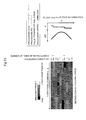
- Fig. 13 is a diagram illustrating a display screen of the display unit that displays the processing records of the burnishing method performed by the burnishing device according to the first embodiment of the invention.
- the display unit 6 displays the pressing force F applied by the roller 13 on X- and Y-coordinates upon the processing, while the displayed pressing force F is distinguished by colors indicating the magnitude of the pressing force F.
- the user can clearly confirm that a part that is insufficiently pressed does not exist.
- the standard displacement u0 and deflection v at both ends in Y-direction, the number of times of reprocessing, a processing direction, the predetermined pitch p, and a processing speed are also displayed for each of processed lines. Thus, a processing state can be checked in detail when necessary.
- the pressing force F to be applied by the pressing unit 13 in the normal direction of the surface (to be processed) of the object 105 to be processed is calculated on the basis of the strain amounts of the burnishing tool 1, and the pressing unit 13 presses the surface (to be processed) on the basis of the calculated pressing force F.
- the burnishing processing can be reliably performed on the surface (to be processed), which is included in the object 105 to be processed and which has a change in height and inclination angle. As a result, the service life of the object 105 to be processed can be increased.
- the displacement u of the arm 25 is controlled on the basis of the pressing force F calculated on the basis of the strain amounts detected by the strain sensors 14a and 14b, it is not necessary that information of the shape of the rotor attachment base 105 be input to the tool driving device 2. In addition, even if a detailed shape of an object to be processed is not clear, the object can be processed.
- the relationships of balance between the pressing force F applied by the roller 13 to the surface (to be processed) of which the inclination angle ⁇ varies, the friction force f applied in the tangential direction of the surface to be processed, the shearing force W of the beam 11, and the axial force B of the beam 11 are calculated as the characteristic relationships between the pressing force F, the shearing force W of the beam 11, and the axial force B of the beam 11, as illustrated in Fig. 8 .
- the pressing force F to be applied by the roller 13 in the normal direction of to the surface (to be processed) of which the inclination angle ⁇ varies can be calculated without measuring the inclination angle ⁇ .
- the burnishing tool 1 uses a beam scheme in which the roller 13 presses the surface using the deflection reaction force of the beam.
- the burnishing tool 1 can reliably perform the burnishing processing on the object (such as the rotor attachment base 105) that is to be processed having a narrow inner surface.
- the measured pressing force F is distinguished by the colors indicating the magnitude of the pressing force F and displayed, the quality of the burnishing can be easily managed in detail when necessary.
- Fig. 14 is a characteristic diagram illustrating the relationship between the pressing force F and deflection of the beam upon the burnishing performed by the burnishing device according to the second embodiment of the invention.
- Reference symbols that are illustrated in Fig. 14 and the same as those illustrated in Figs. 1 to 13 indicate the same parts as those illustrated in Figs. 1 to 13 , and a detailed description thereof is omitted.
- the second embodiment is different in the following point from the first embodiment.
- the burnishing is performed while the displacement u of the arm 25 is fixed, and if a processing failure is detected, the displacement u of the arm 25 is corrected on the basis of the measured pressing force F and the burnishing is performed again.
- the displacement u of the arm 25 is sequentially corrected on the basis of the pressing force F measured during the processing.
- the computer 3 that constitutes a part of the burnishing device according to the second embodiment includes the input/output (I/O) unit 31, the storage unit 32, and the calculator 33 (refer to Fig. 3 ).
- the storage unit 32 stores various characteristic diagrams and various set values in advance.
- the calculator 33 calculates the pressing force F to be applied by the roller 13 in the normal direction of the surface (to be processed) on the basis of values detected by the strain sensors 14a and 14b and the characteristic diagrams and calculates a deflection correction amount ⁇ of the deflection v of the beam 11 on the basis of the calculated pressing force F, the characteristic diagrams, and the set values.
- the storage unit 32 stores the characteristic diagram indicating the relationships of balance between the pressing force, the friction force, the shearing force of the beam 11, and the axial force of the beam 11 upon the burnishing, in order for the calculator 33 to calculate the pressing force F (refer to Fig. 8 ).
- the storage unit 32 stores a characteristic diagram indicating the relationship between the pressing force and the deflection of the beam 11, the allowable pressing force Ft, allowable deflection vt (of the beam 11) corresponding to the allowable pressing force Ft on the characteristic diagram, target pressing force Fm set from the characteristic diagram in order for the pressing force F to be applied by the roller 13 to be equal to or higher than the allowable pressing force Ft, and a target control value vm corresponding to the target pressing force Fm and provided for the deflection v (refer to Fig. 14 described later).
- the calculator 33 acquires the detection signals of the strain sensors 14a and 14b, calculates the pressing force F to be applied by the roller 13 on the basis of the detection signals of the strain sensors 14a and 14b and the characteristic diagram (illustrated in Fig. 8 ) stored in the storage unit 32, and outputs the result of calculating the pressing force F to the storage unit 32 and the display unit 6.
- the calculator 33 sequentially calculates the deflection correction amount ⁇ v of the deflection v of the beam 11 on the basis of the calculated pressing force F and the target pressing force Fm stored in the storage unit 32 so that the pressing force F is equal to the target pressing force Fm, as described later. Then, the calculator 33 sequentially outputs the correction displacement command to change the displacement u of the arm 25 by the deflection correction amount ⁇ v to the tool controller 4.
- Fig. 14 is a characteristic diagram illustrating the relationship between the pressing force and the deflection of the beam upon the burnishing performed by the burnishing device according to the second embodiment of the invention.
- the ordinate indicates the pressing force F to be applied by the roller 13
- the abscissa indicates the deflection v of the beam 11.
- a solid line A is a characteristic curved line indicating the relationship between the pressing force and the deflection of the beam when a condition that causes the ratio F/W (illustrated in Fig. 8 ) to be smallest is selected.
- the allowable pressing force Ft and the allowable deflection vt corresponding to the allowable pressing force Ft are values set to obtain the predetermined compressive residual stress.
- the target pressing force Fm and the target control value vm of the deflection v corresponding to the target pressing force Fm are set in order to control the deflection v of the beam 11 so that the pressing force F to be applied by the roller 13 is maintained at the allowable pressing force Ft or higher.
- the allowable pressing force Ft, the allowable deflection vt, the target pressing force Fm, the target control value vm, and the characteristic diagram are stored in the storage unit 32.
- the deflection correction amount ⁇ v (of the deflection v of the beam 11) that corresponds to the difference ⁇ F is calculated.
- the deflection correction amount ⁇ v is equal to the correction amount of the displacement u of the arm 25.
- the characteristic curved line A illustrated in Fig. 14 indicates the relationship between the pressing force F and the deflection v when the condition that causes the ratio F/W to be smallest is selected on the characteristic diagram illustrated in Fig. 8 . Since the shearing force W is in proportion to the deflection v, the ratio F/v is also smallest. Thus, the pressing force F calculated from the characteristic curved line A is set to a low value for safety.
- Fig. 15 is a flowchart of the burnishing method to be performed by the burnishing device according to the second embodiment of the invention.
- Fig. 16 is a characteristic diagram indicating the relationship between the shearing force of the beam and the deflection of the beam upon the burnishing performed by the burnishing device according to the second embodiment of the invention.
- Reference symbols that are illustrated in Figs. 15 and 16 and the same as those illustrated in Figs. 1 to 14 indicate the same parts as those illustrated in Figs. 1 to 14 , and a detailed description thereof is omitted.
- Fig. 15 and 16 and the same as those illustrated in Figs. 1 to 14 indicate the same parts as those illustrated in Figs. 1 to 14 , and a detailed description thereof is omitted.
- the direction in which the burnishing tool is inserted is X-direction
- the direction in which the groove bottom portions of the rotor attachment bases extend is Y-direction
- the direction in which the burnishing tool is pressed against the rotor attachment base 105 is Z-direction.
- the shearing force W0 that is higher than the maximum shearing force Wmax estimated to be applied to the beam 11 upon the processing is applied to the beam 11 before the burnishing processing (in step S21).
- Fig. 16 is a characteristic diagram illustrating the relationship the shearing force of the beam and the deflection of the beam upon the burnishing performed by the burnishing device according to the second embodiment of the invention.
- the ordinate indicates the shearing force W of the beam
- the abscissa indicates the deflection v of the beam 11.
- a solid line A is a characteristic curved line indicating the relationship between the shearing force of the beam and the deflection of the beam under the condition that the ratio B/W is 0 and causes the ratio F/W to be smallest.
- the maximum shearing force Wmax is determined as the shearing force to be applied to the beam 11 when the deflection v of the beam 11 is estimated to be shifted by up to a value ⁇ vmax from the target control value vm.
- the maximum shearing force Wmax (of the beam) calculated from the characteristic curved line A is set to a high value for safety.
- the beam 11 illustrated in Fig. 3 is moved in X-direction, the edge of the beam 11 is inserted in a gap between the rotor attachment bases 105, and the roller 13 is set on the groove bottom portion 107 of the rotor attachment base 105 at the X-directional processing start position at which the processing starts to be performed (in step S22).
- the beam 11 is moved in Z-direction (pressing direction) and the roller 13 is pressed against the groove bottom portion 107 (in step S23).
- the strain sensors 14a and 14b detect the strain amounts of the beam 11 and output the strain amounts to the calculator 33.
- the calculator 33 acquires the strain amounts detected by the strain sensors 14a and 14b, calculates the pressing force F on the basis of the strain amounts and the characteristic diagram (illustrated in Fig. 8 ) stored in the storage unit 32, and outputs the result of calculating the pressing force F to the display unit 6 (in step S24).
- the pressing force F is displayed on the display unit 6.
- the displacement u of the arm 25 in Z-direction is set so that the pressing force F to be applied by the roller 13 is equal to the target pressing force Fm (in step S25).
- the target pressing force Fm is set so that the pressing force F applied by the roller 13 can be maintained at the allowable pressing force Ft or higher even if the deflection v of the beam 11 is shifted by up to the value ⁇ vmax from the target control value vm.
- the roller 13 is moved on the groove bottom portion 107 in Y-direction (groove direction) and processes the groove bottom portion 107 (in step S26). During the processing, the deflection v of the beam 11 and the pressing force F applied by the roller 13 change with a variation in the standard displacement u0.
- the calculator 33 acquires the strain amounts detected by the strain sensors 14a and 14b, calculates the pressing force F on the basis of the strain amounts and the characteristic diagram (illustrated in Fig. 8 ) stored in the storage unit 32, and outputs the result of calculating the pressing force F to the storage unit 32 and the display unit 6 (in step S27).
- the pressing force F is stored in the storage unit 32 and displayed on the display unit 6.
- the calculator 33 controls the tool driving device 2 so that the displacement u of the arm 25 is equal to a value of (u + ⁇ v) (in step S29). Specifically, the calculator 33 outputs, to the tool controller 4 on the basis of the calculated deflection correction amount ⁇ v, a correction displacement command to change the displacement u of the arm 25 by the deflection correction amount ⁇ v and drives the Z-axis driving device 28 through the tool controller 4 so that the displacement u of the arm 25 is equal to the value of (u + ⁇ v).
- step S30 it is determined whether or not the roller 13 has reached an end to be processed in Y-direction (in step S30). If the roller 13 has yet to reach the end to be processed in Y-direction, the process returns to step S27. If the roller 13 has reached the end to be processed in Y-direction, the process proceeds to step S31.
- step S30 If the roller 13 has yet to reach the end to be processed in Y-direction (No in step S30), the processing in Y-direction is continuously performed by causing the process to return to step S26 and repeating the aforementioned procedure until the roller 13 reaches the end to be processed in Y-direction.
- the calculator 33 sequentially calculates the pressing force F on the basis of the strain amounts detected by the strain sensors 14a and 14b, calculates the correction amount ⁇ v of the deflection v of the beam 11 on the basis of the result of calculating the pressing force F, and sequentially controls the displacement u of the arm 25 on the basis of the deflection correction amount ⁇ v so that the displacement u of the arm 25 is equal to the value of (u + ⁇ v) during the processing of one line.
- the displacement u of the arm 25 is sequentially controlled so that the pressing force F applied by the roller 13 is maintained at the target pressing force Fm.
- the processing in Y-direction is progressed while feedback control is performed so as to maintain the pressing force F at the target pressing force Fm.
- step S30 When the roller 13 reaches the end to be processed in Y-direction (Yes in step S30), the roller 13 is shifted by the predetermined pitch p in X-direction and set to process the next line in the opposite direction (in step S31). In this case, the roller 13 is set in order to prepare to process the next line. In the present embodiment, the roller 13 is shifted by the pitch p in X-direction upon the completion of the processing of each of the lines in Y-direction, and the lines are processed in the opposite direction so that the overall groove bottom portion 107 is processed by the burnishing.
- step S32 it is determined whether or not the roller 13 has reached the X-directional processing end position at which the processing is completed. If the roller 13 has yet to reach the X-directional processing end position at which the processing is completed (No in step S32), the process returns to step S23, and the next line is processed by repeating the aforementioned procedure. If the roller 13 has reached the X-directional processing end position at which the processing is completed (Yes in step S32), the processing is completed.
- steps S21 to S23, S25, S26, S31, and S32 are manually performed, but may be automatically performed by control of the computer.
- the burnishing device and the burnishing method performed by the burnishing device according to the second embodiment can obtain effects that are the same as those obtained in the first embodiment.
- the displacement u of the arm 25 is sequentially corrected during the processing of one line so that the pressing force F applied by the roller 13 is maintained at the target pressing force Fm during the processing of one line, a step of reprocessing a line due to insufficiency of the pressing force F applied by the roller 13 is not necessary, and the time for the processing can be reduced.
- Fig. 17 is a diagram illustrating the burnishing device according to the third embodiment of the invention and the relationship between the pressing force and the friction force that are applied to the inclined surface to be processed and shearing force and axial force that are applied to an axial force shaft upon the burnishing.
- Fig. 18 is a diagram describing the burnishing performed on a blade attachment base of a turbine blade by the burnishing device according to the third embodiment of the invention.
- Fig. 19 is a characteristic diagram indicating relationships of balance between the pressing force, the friction force, the shearing force of the axial force shaft, and the axial force of the axial force shaft upon the burnishing by the burnishing device according to the third embodiment of the invention.
- Reference numerals and symbols that are illustrated in Figs. 17 to 19 and the same as those illustrated in Figs. 1 to 16 indicate the same parts as those illustrated in Figs. 1 to 16 , and a detailed description thereof is omitted.
- a burnishing tool 50 (illustrated in Fig. 17 ) that is included in the burnishing device according to the third embodiment of the invention uses axial force to press an edge of the tool against the object to be processed in the third embodiment.
- the burnishing tool 50 includes the axial force shaft 51, a fixing portion 52, a roller 53, and a spring mechanism 54 for displacement absorption.
- the fixing portion 52 is arranged at one end of the axial force shaft 51 in a longitudinal direction of the axial force shaft 51.
- the roller 53 is arranged on a surface of the other end of the axial force shaft 51 in the longitudinal direction of the axial force shaft and serves as a pressing unit that presses the surface (to be processed) of the object to be processed.
- the spring mechanism 54 is arranged in the axial force shaft 51.
- the burnishing tool 50 uses the axial force of the axial force shaft 51 to cause the roller 53 to press the surface to be processed.
- the roller 53 is capable of rotating around an axial direction perpendicular to the longitudinal direction of the axial force shaft 51.
- the spring mechanism 54 has a function of using a spring 55 included in spring mechanism 54 to absorb a variation in the height of the surface to be processed during the processing, preventing the pressing force F applied by the axial force shaft 51 from excessively varying, and stabilizing the pressing force F.
- Strain sensors 56a and 56b are arranged on upper and lower surfaces (both end portions of the axial force shaft 51 in a shearing direction during the burnishing) of a central portion in the longitudinal direction of the axial force shaft 51.
- the burnishing can be performed on the object (such as the blade attachment base 106 of the turbine blade 103), which is to be processed and in which the burnishing tool 50 can be inserted in the same direction as the pressing direction.
- a method for pressing the surface (to be processed) using the axial force of the axial force shaft 51 is used instead of the deflection reaction force of the beam 11 that constitutes a part of the burnishing device according to the first embodiment, and the following equations for calculating the pressing force F from values measured by the strain sensors 56a and 56b are used, unlike the first embodiment.
- the axial force Bs of the shaft 51 and the shearing force Ws of the shaft 51 are calculated according to the following Equations (8) and (9) using strain amounts ⁇ a, ⁇ b measured by the strain sensors 56a and 56b.
- Bs ⁇ a + ⁇ b / 2 ⁇ Es ⁇
- Ws ⁇ a - ⁇ b / 2 ⁇ Es ⁇ Zs / Ls
- Es is a Young's modulus of the axial force shaft 51
- Zs is a section modulus of the axial force shaft 51
- As is a cross-sectional area of the axial force shaft 51
- Ls is a distance between an edge of the roller 53 and the strain sensors 56a and 56b.
- Equation (12) ⁇ is a coefficient of friction.
- Equations (10) to (12) can be represented as the characteristic diagram illustrated in Fig. 19 .
- the ordinates indicates the ratio F/Bs of the pressing force F applied by the roller 53 to the axial force Bs of the shaft 51
- the abscissa indicates the ratio Ws/Bs of the shearing force Ws of the shaft 51 to the axial force Bs of the shaft 51.
- a solid line A, a broken line B, and a dotted line C are characteristic curved lines obtained in the cases where the coefficient ⁇ of friction are 0.15, 0.3, 0.6, respectively.
- An appropriate coefficient ⁇ of friction is selected on the basis of results measured by a separate examination.
- the axial force Bs of the shaft 51 and the shearing force Ws of the shaft 51 are calculated using Equations (8) and (9) on the basis of the values measured by the strain sensors 56a and 56b.
- the ratio F/Bs (indicated by the ordinate) is calculated from the ratio Ws/Bs (indicated by the abscissa) determined by the axial force Bs and shearing force Ws that are calculated using a characteristic curved line that is selected on the basis of the results of examining the coefficient ⁇ of friction from among the characteristic curved lines A, B, and C indicated in the characteristic diagram illustrated in Fig. 19 .
- the pressing force F can be calculated from the ratio F/Bs.
- the ratio F/Bs is not uniquely determined.
- a value (plot in Fig. 19 ) on a curved line is used in order to estimate a low value for safety.
- an error of the ratio F/Bs (indicated by the ordinate) is up to 14% even when the coefficient ⁇ of friction is 0.6.
- the pressing force F can be calculated without measuring the inclination angle ⁇ for the burnishing performed on the object (to be processed) of which the inclination angle ⁇ of the surface (to be processed) (such as the blade attachment base 106) varies.
- the burnishing method used in the first and second embodiments can be used.
- the axial force Bs of the shaft 51 is used to press the surface to be processed
- the axial force Bs of the shaft 51 is used for a variation in the pressing direction of the burnishing tool, instead of the shearing force W of the beam 11.
- the deflection reaction force of the beam is used to press the surface to be processed in the first and second embodiments.
- the burnishing device uses the method for pressing the surface using the axial force of the axial force shaft 51.
- the burnishing processing can be reliably performed on a surface (to be processed) of an object (such as the blade attachment base 106 of the turbine blade 103) in which the burnishing tool can be inserted in the same direction as the pressing direction, while the height and inclination angle of the surface to be processed vary.
- the first embodiment describes the example in which the rotor attachment base 105 of the rotor disk 102 is used as the object to be processed
- the blade attachment base 106 of the turbine blade 103 may be used as the object to be processed.
- the first to third embodiments describe the example in which the rotor attachment base 105 of the rotor disk 102 and the blade attachment base 106 of the turbine blade 103 are processed, an object that is to be processed and has a surface which has a change in height and inclination angle may be processed.
- the burnishing devices according to the first to the third embodiment are effective to process, for example, a device that is a bearing housing of a vehicle part or the like and has a corner portion in order to improve the strength of the device.
- the roller is used as a pressing unit in each of the first to third embodiments, it is sufficient if the pressing unit forms a compressive residual stress layer on an object to be processed, and a ball may be used as the pressing unit.
- the tool driving device 2 can control the burnishing tool in at least X-, Y- and Z-directions.
- the present invention is not limited to the aforementioned embodiments, but covers various modifications. While, for illustrative purposes, those embodiments have been described specifically, the present invention is not necessarily limited to the specific forms disclosed. Thus, partial replacement is possible between the components of a certain embodiment and the components of another. Likewise, certain components can be added to or removed from the embodiments disclosed.
- a processor can interpret and execute the programs designed to serve those functions.
- the programs, associated data tables, files, and the like can be stored on a stationary storage device such as a memory, a hard disk, and a solid state drive (SSD) or on a portable storage medium such as an integrated circuit card (ICC), an SD card, and a DVD.
- a stationary storage device such as a memory, a hard disk, and a solid state drive (SSD) or on a portable storage medium such as an integrated circuit card (ICC), an SD card, and a DVD.
- ICC integrated circuit card
- control lines and information lines shown above represent only those lines necessary to illustrate the present invention, not necessarily representing all the lines required in terms of products. Thus, it can be assumed that almost all the components are in fact interconnected.
Abstract
Description
- The present invention relates to a burnishing device and a burnishing method using it.
- As a method for finishing a surface in order to improve wear resistance and fatigue strength of a metal material, burnishing is known. As a burnishing tool to be used for the burnishing, there is a tool described in
JP-2005-288557-A - The burnishing tool described in
Patent Document 1 is a roller burnishing tool that includes a cylindrical shank, a head, and a roller for compaction. The head is arranged in the shank through a pivot shaft and pivots by work pressing force. The burnishing tool further includes a biasing unit, a biasing force adjusting unit, and a biasing force converting unit. The biasing unit is arranged in the cylindrical shank and biases in a shank axis direction. The biasing force adjusting unit adjusts biasing force generated by the biasing unit. The biasing force converting unit transmits the biasing force to a head shaft and changes a direction of the biasing force to a direction in which the head shaft pivots. The burnishing tool controls the work pressing force to be generated upon rolling compaction. - A part that connects turbine blades of a steam turbine or the like to a turbine rotor disk has a structure in which an attachment base located on the side of the turbine blades is engaged with an attachment base located on the side of the turbine rotor disk. The connection part balances centrifugal force applied to the turbine blades upon an operation of the turbine and thus needs to have sufficient fatigue resistance.
- Although
Patent Document 1 describes the fact that an edge of the burnishing tool is pressed against an inner surface of a cylindrical object, a unit for measuring pressing force is not provided. If the invention described inPatent Document 1 is applied to the part that connects the turbine blades to the turbine rotor disk, there is a problem that compressive residual stress is not reliably formed on a processed part of an attachment base due to displacement of the set attachment base or an error of a dimension of the attachment base. Especially, for a portion (such as the attachment base) of which the height and inclination angle of a surface (to be processed) vary, an error between an input position of the portion and the actual position of the portion easily occurs. Thus, it is likely that the portion may not be sufficiently processed by the burnishing. - The present invention was devised to solve the aforementioned problems, and an object of the invention is to provide a burnishing device and a burnishing method that enable burnishing to be reliably performed on a surface, which is included in an object to be processed and is to be processed by burnishing and has a change in height and inclination angle.
- In order to solve the aforementioned problems, configurations described in claims are used, for example.
- The present specification includes multiple schemes for solving the aforementioned problems. As an example of the schemes, a burnishing device including a burnishing tool having a pressing unit that rotationally presses a surface of an object to be processed, the surface having a change in height and inclination angle; a tool driving device configured to move the burnishing tool; a strain sensor configured to detect a strain amount of the burnishing tool; and/or a computer configured to calculate pressing force to be applied by the pressing unit in a normal direction of the surface of the object to be processed, the calculation being on the basis of the strain amount detected by the strain sensor, calculate a correction amount of displacement of the tool driving device in a pressing direction, the calculation being on the basis of the calculated pressing force and stored pressing force in advance, and/or output the correction amount to the tool driving device.
- According to the invention, the pressing force to be applied by the pressing unit in the normal direction of the surface of the object to be processed is calculated on the basis of the strain amount of the burnishing tool, the pressing unit presses the surface by the calculated pressing force, and the burnishing processing can be reliably performed on the surface, which is included in the object to be processed and has a change in height and inclination angle. As a result, the service life of the object to be processed can be increased.
- Challenges, configurations, and effects other than those described above are clarified by the following description of embodiments.
-
-
Fig. 1 is a perspective view partially illustrating turbine blades of a steam turbine to be processed using a burnishing method by a burnishing device according to each embodiment of the invention. -
Fig. 2 is an enlarged perspective view of a part indicated by a symbol A inFig. 1 , which shows a connection of turbine blades and a turbine rotor disk in the steam turbine. -
Fig. 3 is an outline configuration diagram illustrating a burnishing device according to a first embodiment of the invention. -
Fig. 4 is an enlarged perspective view illustrating a roller of a burnishing tool that constitutes a part of the burnishing device (illustrated inFig. 3 ) according to the first embodiment of the invention. -
Fig. 5 is a diagram describing a burnishing process to be performed by the burnishing device according to the first embodiment of the invention. -
Fig. 6 is a diagram illustrating the relationship between deflection of a beam and displacement of an arm upon the burnishing performed by the burnishing device according to the first embodiment of the invention. -
Fig. 7 is a diagram illustrating the relationship between pressing force and friction force that are applied to an inclined surface (to be processed) and shearing force and axial force that are applied to the beam upon the burnishing performed by the burnishing device according to the first embodiment of the invention. -
Fig. 8 is a characteristic diagram illustrating relationships of balance between the pressing force, the friction force, the shearing force of the beam, and the axial force of the beam upon the burnishing performed by the burnishing device according to the first embodiment of the invention. -
Fig. 9 is a characteristic diagram illustrating the relationship between the pressing force and the deflection of the beam upon the burnishing performed by the burnishing device according to the first embodiment of the invention. -
Fig. 10 is a flowchart of a burnishing method to be performed by the burnishing device according to the first embodiment of the invention. -
Fig. 11 is a diagram illustrating displacement of a chucking of the burnishing tool that constitutes the part of the burnishing device according to the first embodiment of the invention. -
Fig. 12 is a characteristic diagram illustrating the relationship between the shearing force of the beam and the deflection of the beam upon the burnishing performed by the burnishing device according to the first embodiment of the invention. -
Fig. 13 is a diagram illustrating a display screen of a display unit that displays processing records of the burnishing method performed by the burnishing device according to the first embodiment of the invention. -
Fig. 14 is a characteristic diagram illustrating the relationship between pressing force and deflection of the beam upon burnishing performed by the burnishing device according to a second embodiment of the invention. -
Fig. 15 is a flowchart of a burnishing method to be performed by the burnishing device according to the second embodiment of the invention. -
Fig. 16 is a characteristic diagram illustrating the relationship between shearing force of the beam and the deflection of the beam upon the burnishing performed by the burnishing device according to the second embodiment of the invention. -
Fig. 17 is a diagram illustrating a burnishing device according to a third embodiment of the invention and the relationship between pressing force and friction force that are applied to an inclined surface (to be processed) and shearing force and axial force that are applied to an axial force shaft upon the burnishing. -
Fig. 18 is a diagram describing the burnishing to be performed on a blade attachment base of a turbine blade by the burnishing device according to the third embodiment of the invention. -
Fig. 19 is a characteristic diagram illustrating relationships of balance between the pressing force, the friction force, the shearing force of an axial force shaft, and the axial force of the axial force shaft upon the burnishing performed by the burnishing device according to the third embodiment of the invention. - Hereinafter, a burnishing device and a burnishing method according to first to third embodiments of the invention are described with reference to the accompanying drawings.
- First, the configuration of a steam turbine to be processed using the burnishing method by the burnishing device according to the first to third embodiments of the invention is described with reference to
Figs. 1 and 2 . -
Fig. 1 is a perspective view partially illustrating turbine blades of the steam turbine to be processed using the burnishing method by the burnishing device.Fig. 2 is an enlarged perspective view of a part indicated by a symbol A inFig. 1 , which shows a connection of turbine blades and a turbine rotor disk in the steam turbine. - In
Fig. 1 , theturbine 100 includes arotor shaft 101, theturbine rotor disk 102, and the plurality ofturbine blades 103. Theturbine rotor disk 102 is attached to an outer circumferential portion of therotor shaft 101. Theturbine blades 103 are connected to an outer circumferential portion of theturbine rotor disk 102 at intervals. - As illustrated in
Fig. 2 , thepart 104 that connects theturbine rotor disk 102 to theturbine blades 103 has such a structure:rotor attachment bases 105 of theturbine rotor disk 102 are engaged withblade attachment bases 106 of theturbine blades 103,attachment bases - During an operation of the turbine, the connected
rotor shaft 101 is rotated by causing theturbine blades 103 to receive steam, and a generator (not illustrated) generates power by rotational driving force of therotor shaft 101. In this case, centrifugal force acts on the rotatingturbine blades 103 and is supported by theconnection part 104 having the engagement structure. Thereby, stress is concentrated atgroove bottom portions 107 of therotor attachment bases 105 andgroove bottom portions 108 of theblade attachment bases 106. Thus generated locally high stress may cause damage such as a fatigue crack or stress corrosion cracking under long-term use. - As a technique for suppressing such damage, burnishing, which suppresses the occurrence or progress of a crack or the like by forming a compressive residual stress layer on a surface, is effective. The burnishing has advantages that the formed compressive residual stress layer is deep, a processed surface is smooth, and the processing cost is low.
- Next, the burnishing device according to the first embodiment of the invention is described with reference to
Figs. 3 to 6 . -
Fig. 3 is an outline configuration diagram illustrating the burnishing device according to the first embodiment of the invention.Fig. 4 is an enlarged perspective view illustrating a roller of a burnishing tool that constitutes a part of the burnishing device (illustrated inFig. 3 ) according to the first embodiment of the invention.Fig. 5 is a diagram describing a burnishing process to be performed by the burnishing device according to the first embodiment of the invention.Fig. 6 is a diagram illustrating the relationship between deflection of a beam and displacement of an arm upon the burnishing performed by the burnishing device according to the first embodiment of the invention. Reference numerals that are illustrated inFigs. 3 to 6 and the same as those illustrated inFigs. 1 and 2 indicate the same parts as those illustrated inFigs. 1 and 2 , and a detailed description thereof is omitted. InFigs. 3 ,5 , and6 , a direction in which the burnishing tool is inserted is X-direction, a direction in which the groove bottom portions of the rotor attachment bases extend is Y-direction, and a direction in which the burnishing tool presses the rotor attachment base is Z-direction. - The present embodiment describes an example in which a surface processed inside of the
rotor attachment base 105 of the rotor disk is subjected to burnishing. Prior to burnishing, the surface processed is formed in a narrow inner surface shape and has a change in height and inclination angle. - In
Fig. 3 , the burnishing device includes aburnishing tool 1 and atool driving device 2. Theburnishing tool 1 forms a compressive residual stress layer on an object (rotor attachment bases 105) to be processed. Thetool driving device 2 moves theburnishing tool 1 in X-, Y-, and Z-directions. - The
burnishing tool 1 uses a beam scheme in consideration of access to thegroove bottom portions 107 of the rotor attachment bases 105 having the narrow inner surface. In the beam scheme, deflection reaction force of abeam 11 is used to press an edge of theburnishing tool 1 against the surface to be processed. Theburnishing tool 1 includes thebeam 11, a fixingportion 12, and aroller 13. Thebeam 11 can be inserted in a narrow portion of therotor attachment base 105. The fixingportion 12 is arranged at one edge of thebeam 11 in a longitudinal direction of thebeam 11. Theroller 13 serves as a pressing unit that presses the surface (to be processed) of the object to be processed. As illustrated inFig. 4 , theroller 13 is capable of rotating around an axial direction (X-direction) parallel to the longitudinal direction of thebeam 11. - The
tool driving device 2 includes abase portion 21, a Y-axis stage 22, a Y-axis driving device 23, a holdingportion 24, anarm 25, anX-axis driving device 26, anarm holding portion 27, a Z-axis driving device 28, and atool gripping portion 29. The Y-axis stage 22 is capable of moving in Y-direction relative to thebase portion 21. The Y-axis driving device 23 moves the Y-axis stage 22. The holdingportion 24 stands on the Y-axis stage 22. Thearm 25 is attached to the holdingportion 24 and capable of moving in X-direction. TheX-axis driving device 26 moves thearm 25 relative to the holdingportion 24 in X-direction. Thearm holding portion 27 holds thearm 25 and is capable of moving relative to the holdingportion 24 in Z-direction. The Z-axis driving device 28 moves thearm holding portion 27 relative to the holdingportion 24 in Z-direction. Thetool gripping portion 29 is arranged at an edge of thearm 25. - The
tool gripping portion 29 has achucking hole 29a. Theburnishing tool 1 is fixed to thechucking hole 29a by inserting the fixingportion 12 of theburnishing tool 1 in thechucking hole 29a and bolting the fixingportion 12. - The
burnishing tool 1 is moved in X-direction by theX-axis driving device 26 and inserted in a gap between the rotor attachment bases 105. Next, theburnishing tool 1 is moved in Z-direction by the Z-axis driving device 28 and theroller 13 of theburnishing tool 1 is pressed against thegroove bottom portion 107 of therotor attachment base 105. While theroller 13 is pressed against thegroove bottom portion 107, theburnishing tool 1 is moved in Y-direction by the Y-axis driving device 23 and theroller 13 is moved in a groove direction (Y-direction) while rotationally pressing the groove bottom portion 107 (or processing one line), as illustrated inFig. 4 . - When the
roller 13 finishes moving from one end to the other end of thegroove bottom portion 107 in Y-direction while pressing the surface to be processed, theroller 13 is moved in X-direction by a predetermined pitch p by theX-axis driving device 26 as illustrated inFig. 5 . In addition, the Z-axis driving device 28 is driven to cause theroller 13 to be pressed against thegroove bottom portion 107 again and theroller 13 is moved from the other end to one end of thegroove bottom portion 107 in Y-direction while pressing thegroove bottom portion 107. By repeating this operation, the burnishing is completed on the overallgroove bottom portion 107. - In this case, local plastic deformation occurs at a contact portion of the surface (to be processed) by pressing force F applied to the surface (to be processed) in a normal direction of the surface by the
roller 13, and compressive residual stress is formed at the contact portion. The pressing force F applied to the surface (to be processed) in the normal direction correlates with the magnitude of the compressive residual stress formed by the burnishing. - Necessary allowable pressing force Ft is determined in advance to obtain predetermined compressive residual stress or higher, and deflection v of the
beam 11 is controlled by thetool driving device 2 so that the pressing force F is not lower than the allowable pressing force Ft. - A configuration that is provided to control the deflection v of the
beam 11 and effect of the configuration are described below. - As illustrated in
Fig. 6 , the deflection v of thebeam 11 is represented by the following Equation (1) using displacement u of thearm 25 of thetool driving device 2 in Z-direction (pressing direction).
- In Equation (1), u0 is standard displacement of the
arm 25 in Z-direction when theroller 13 starts contacting the surface (to be processed) of the object (rotor attachment base 105) to be processed. In Equation (1), u0 is a function of a coordinate x of thegroove bottom portion 107 in X-direction. - In the present embodiment, therefore, the pressing force F to be applied by the
roller 13 is measured to control the deflection v of thebeam 11. - Returning to
Fig. 3 ,strain sensors beam 11 in a shearing direction upon the burnishing) of thebeam 11 in the vicinity of the fixingportion 12. Thestrain sensors computer 3. Thestrain sensors beam 11 and output detection signals corresponding to the amounts of the strains to thecomputer 3. - The
computer 3 is connected to atool controller 4 that drives theX-axis driving device 26, Y-axis driving device 23, and Z-axis driving device 28 of thetool driving device 2 and controls the position of thearm 25. In addition, thecomputer 3 is connected to aninput unit 5, a display unit 6, and an alarm unit 7. Theinput unit 5 is a keyboard or the like and provides a command to display data measured upon the burnishing and provides a various commands (from a user) such as processing requirements for the burnishing and a control value of displacement u of thearm 25 of thetool driving device 2. The display unit 6 displays the data measured upon the burnishing and the like. The alarm unit 7 provides an alarm sound. - The
computer 3 includes an input/output (I/O)unit 31, astorage unit 32, and acalculator 33. Thestorage unit 32 stores various characteristic diagrams and various set values. Thecalculator 33 calculates, on the basis of the detection values received from thestrain sensors roller 13 to the surface (to be processed) in the normal direction of the surface to be processed. Thecalculator 33 compares the calculated pressing force F with a set value and calculates a correction amount δu of the displacement u of thearm 25 in the pressing direction on the basis of the calculated pressing force F, the characteristic diagrams, and the set value. - The
storage unit 32 stores a characteristic diagram (refer toFig. 8 described later) indicating relationships of balance between the pressing force F, friction force, shearing force of thebeam 11, and axial force of thebeam 11 upon the burnishing in order for thecalculator 33 to calculate the pressing force F. In addition, thestorage unit 32 stores the allowable pressing force Ft that is the set value to be used for the comparison with the calculated pressing force F and determination of whether the calculated pressing force F is equal to or larger than pressing force that enables predetermined compressive residual stress to be formed. Furthermore, thestorage unit 32 stores a characteristic diagram indicating the relationship between the pressing force and the deflection of thebeam 11 and stores allowable deflection vt (of the beam 11) corresponding to the allowable pressing force Ft on the characteristic diagram in order for thecalculator 33 to calculate the correction amount δu of the displacement u of the arm 25 (refer toFig. 9 described later). - In addition, the
storage unit 32 stores the processing requirements (for the burnishing) input from theinput unit 5, the result of calculating the pressing force F by thecalculator 33, and the like. - The
calculator 33 acquires the detection signals of thestrain sensors strain sensors Fig. 8 described later) stored in thestorage unit 32, and outputs the result of the calculation to thestorage unit 32 and the display unit 6. In addition, thecalculator 33 determines whether or not the calculated pressing force F is lower than the allowable pressing force Ft stored in thestorage unit 32. If thecalculator 33 determines that the calculated pressing force F is lower than the allowable pressing force Ft, thecalculator 33 outputs an alarm command signal to the alarm unit 7, calculates the correction amount δu (of the displacement u of the arm 25) causing the pressing force F to be equal to or higher than the allowable pressing force Ft, and outputs the result of calculating the correction amount δu to the display unit 6. Furthermore, thecalculator 33 outputs, to thetool controller 4, a correction displacement command to change the displacement u of thearm 25 by the correction amount δu on the basis of the correction amount δu (of the displacement u of the arm 25) input from theinput unit 5. - The input/
output unit 31 receives the detection signals of thestrain sensors input unit 5. In addition, the input/output unit 31 outputs the result (received from the calculator 33) of calculating the pressing force F to the display unit 6, outputs the alarm command signal received from thecalculator 33 to the alarm unit 7, outputs the result (received from the calculator 33) of calculating the correction amount δu of the displacement u of thearm 25 to the display unit 6, and outputs the correction displacement command received from thecalculator 33 to thetool controller 4. - Next, a specific method for calculating the pressing force F (to be applied by the roller 13) by the
calculator 33 on the basis of values measured by thestrain sensors Figs. 7 and8 . -
Fig. 7 is a diagram illustrating the relationship between the pressing force and the friction force that are applied to the inclined surface (to be processed) and the shearing force and the axial force that are applied to the beam upon the burnishing performed by the burnishing device according to the first embodiment of the invention.Fig. 8 is a characteristic diagram illustrating the relationships of balance between the pressing force, the friction force, the shearing force of the beam, and the axial force of the beam upon the burnishing performed by the burnishing device according to the first embodiment of the invention. Reference numerals and symbols that are illustrated inFigs. 7 and8 and the same as those illustrated inFigs. 1 to 6 indicate the same parts as those illustrated inFigs. 1 to 6 , and a detailed description thereof is omitted. - The shearing force W and axial force B of the
beam 11 that are illustrated inFig. 7 are calculated from the following Equations (2) and (3) using strain amounts εa and εb measured by thestrain sensors 

- In Equations (2) and (3), E is a Young's modulus of the
beam 11, Z is a section modulus of thebeam 11, A is a cross-sectional area of thebeam 11, and L is a distance between theroller 13 and thestrain sensors 14A and 14b. - At an edge portion of the
beam 11, the pressing force F applied by theroller 13 to the surface to be processed in the normal direction of the surface to be processed, the friction force f applied in the tangential direction of the surface to be processed, the shearing force W of thebeam 11, and the axial force B of thebeam 11 are balanced. When the inclination angle of the surface to be processed is θ (absolute value), the following Equations (4) to (6) are established on the basis of balance of force acting in vertical and horizontal directions.


- In Equation (6), µ is a coefficient of friction.
- When the inclination angle θ of the surface to be processed is small, the shearing force W of the
beam 11 is generated on the basis of the deflection v of thebeam 11, the shearing force W and the pressing force F and the friction force f are balanced, and the axial force B of thebeam 11 is 0. In this case, since theroller 13 does not slide on the surface to be processed and the forces are balanced, µF > Ftanθ and the friction force f is equal to Ftanθ. - On the other hand, if the inclination angle θ of the surface to be processed is large, horizontal force of only the pressing force F, the friction force f, and the shearing force W of the
beam 11 is not balanced, theroller 13 tries to slide on the surface to be processed and the axial force B is applied to thebeam 11. In this case, since theroller 13 tries to slide on the surface to be processed, µF < Ftanθ and the friction force f is equal to µF. - The relationships of Equations (4) to (6) can be represented by the characteristic diagram illustrated in
Fig. 8 . InFig. 8 , the ordinate indicates the ratio F/W of the pressing force F applied by theroller 13 to the shearing force W of thebeam 11, and the abscissa indicates the ratio B/W of the axial force B of thebeam 11 to the shearing force W of thebeam 11. InFig. 8 , a solid line A, a broken line B, and a dotted line C are characteristic curved lines obtained in the cases where the respective coefficients µ of friction are 0.15, 0.3, and 0.6. Here, an appropriate coefficient µ of friction is selected on the basis of results measured by a separate examination. - Since the shearing force W and the axial force B are calculated using Equations (2) and (3) from the values measured by the
strain sensors - If the axial force B of the
beam 11 is 0, the ratio F/W indicated by the ordinate is not uniquely determined, and a value (plot inFig. 8 ) on a curved line is used in order to estimate a low ratio F/W for safety. In this case, if the coefficient µ of friction is 0.6, an error of the ratio F/W indicated by the ordinate is up to 14%. - In this manner, the pressing force F can be calculated without measuring the inclination angle θ for the burnishing to be performed on the object (to be processed) of which the inclination angle θ of the surface (to be processed) such as the
rotor attachment base 105 varies. - Next, a specific method for calculating the correction amount δu of the displacement u of the
arm 25 by thecalculator 33 is described with reference toFig. 9 . -
Fig. 9 is a characteristic diagram illustrating the relationship between the pressing force and the deflection of the beam upon the burnishing performed by the burnishing device according to the first embodiment of the invention. InFig. 9 , the ordinate indicates the pressing force F applied by theroller 13, and the abscissa indicates the deflection v of thebeam 11. A characteristic curved line A illustrated inFig. 9 indicates the relationship between the pressing force F and the deflection v of the beam when a condition that causes the ratio F/W inFig. 8 to be smallest is selected. - In
Fig. 9 , the allowable pressing force Ft and the allowable deflection vt corresponding to the allowable pressing force Ft are set values to be used to obtain the predetermined compressive residual stress. - Even if the standard displacement u0 varies by the maximum variation δu0 during the time when one line of the
groove bottom portion 107 of therotor attachment base 105 is processed, initial pressing force Fs and initial deflection vs corresponding to the initial pressing force Fs are set so that the pressing force F applied by theroller 13 is maintained at the allowable pressing force Ft or higher. - The initial pressing force Fs is a standard value to be used to determine a start position of the displacement u of the
arm 25 for the processing of one line. - A variation in the standard displacement u0 during the processing of one line occurs due to rotational displacement of the
rotor attachment base 105 in Z-direction upon setting of therotor attachment base 105 and an error of dimensions of therotor attachment base 105. For example, an initial value of the maximum variation δu0 of the standard displacement u0 is set to 0.5 mm. When the pressing force F applied by theroller 13 is lower than the allowable pressing force Ft and the burnishing processing is performed again, the maximum variation δu0 is changed on the basis of the correction value δu of the displacement u of thearm 25. - The allowable pressing force Ft, the allowable deflection vt, the initial pressing force Fs, the initial deflection vs, and the characteristic diagram are stored in the
storage unit 32. - In
Fig. 9 , the minimum deflection vmin is calculated from the minimum pressing force Fmin that is lower than the allowable pressing force Ft and among pressing force F measured during the time when one line of therotor attachment base 105 is processed in the groove direction. The correction amount δu of the displacement u of thearm 25 is calculated according to the following Equation (7) using the minimum deflection vmin, the initial deflection vs, and the maximum variation δu0 of the standard displacement u0.
- In this manner, when the displacement u of the
arm 25 is changed by the correction amount δu, the pressing force F becomes equal to or higher than the allowable pressing force Ft, as is apparent fromFig. 9 . - The characteristic curved line A illustrated in
Fig. 9 indicates the relationship between the pressing force F and the deflection v when the condition that causes the ratio F/W indicated in the characteristic diagram ofFig. 8 to be smallest is selected. Since the shearing force W is in proportion to the deflection v, the ratio F/v is also smallest. The pressing force F calculated from the characteristic curved line A is set to a low value for safety. - Next, a burnishing method that is performed by the burnishing device according to the first embodiment of the invention is described with reference to
Figs. 3 to 6 and8 to 12 . -
Fig. 10 is a flowchart of the burnishing method to be performed by the burnishing device according to the first embodiment of the invention.Fig. 11 is a diagram illustrating displacement of a chucking of the burnishing tool that constitutes a part of the burnishing device according to the first embodiment of the invention.Fig. 12 is a characteristic diagram illustrating the relationship between the shearing force of the beam and the deflection of the beam upon the burnishing performed by the burnishing device according to the first embodiment of the invention. Reference numerals and symbols that are illustrated inFigs. 10 to 12 and the same as those illustrated inFigs. 1 to 9 indicate the same parts as those illustrated inFigs. 1 to 9 , and a detailed description thereof is omitted. InFig. 10 , the direction in which the burnishing tool is inserted is X-direction, the direction in which the groove bottom portions of the rotor attachment bases extend is Y-direction, and the direction in which the burnishing tool presses the rotor attachment base is Z-direction. - As illustrated in
Fig. 10 , shearing force W0 that is higher than the maximum shearing force Wmax estimated to be applied to thebeam 11 upon the burnishing processing is applied to thebeam 11 before the burnishing processing (in step S1). - The maximum shearing force Wmax is shearing force applied to the
beam 11 due to the maximum variation of the standard displacement u0 during the time when one line of thegroove bottom portion 107 illustrated inFig. 3 is processed in the groove direction (Y-direction). - When shearing force that is equal to or higher than a certain level is applied to the
beam 11, the chucking is displaced in theburnishing tool 1 inserted in and fixed to thechucking hole 29a of thetool gripping portion 29, as illustrated inFig. 11 . InFig. 11 , theburnishing tool 1 indicated by a two-dot chain line is in a state in which the chucking is not displaced, and theburnishing tool 1 indicated by a solid line is in a state in which the chucking is displaced. - If the shearing force W0 that is higher than the maximum shearing force Wmax estimated to be applied to the
beam 11 upon the burnishing processing is applied to thebeam 11 in advance and the chucking of theburnishing tool 1 is displaced, further displacement of the chucking during the burnishing processing can be suppressed by the processing performed by theburnishing tool 1 in the state in which the chucking is displaced. - If the shearing force W0 is applied to the
beam 11 in advance and the chucking of theburnishing tool 1 is not displaced, shearing force that is equal to or higher than the shearing force W0 is not applied to thebeam 11 during the processing, and it is considered that the chucking of theburnishing tool 1 is not displaced. - It is, therefore, possible to suppress a reduction in the pressing force F to a value lower than the allowable pressing force Ft due to displacement of the chucking of the
burnishing tool 1 during the processing. - Next, a method for determining the maximum shearing force Wmax of the
beam 11 is described with reference toFig. 12 . -
Fig. 12 is a characteristic diagram illustrating the relationship between the shearing force of thebeam 11 and the deflection of thebeam 11 upon the burnishing performed by the burnishing device according to the first embodiment of the invention. InFig. 12 , the ordinate indicates the shearing force W of thebeam 11, and the abscissa indicates the deflection v of thebeam 11. A solid line A illustrated inFig. 12 is a characteristic curved line indicating the relationship between the deflection of the beam and the shearing force of the beam when the ratio B/W is 0 and causes the ratio F/W to be smallest inFig. 8 . - It is assumed that the variation in the standard displacement u0 during the time when one line is processed is in a range of ±0.5 mm. In this case, the maximum shearing force Wmax is determined so that the deflection v is equal to or larger than the allowable deflection vt while the variation in the standard displacement u0 is in the range of ±0.5 mm. In this case, the maximum variation δu0 in the standard displacement u0 is set to an initial value of 0.5 mm.
- Since the characteristic curved line A illustrated in
Fig. 12 indicates the relationship between the deflection of the beam and the shearing force of the beam when the ratio B/W is 0 and causes the ratio F/W to be smallest inFig. 8 , the maximum shearing force Wmax (of the beam) calculated from the characteristic curved line A is set to a high value for safety. - Returning to
Fig. 10 , theX-axis driving device 26 of thetool driving device 2 illustrated inFig. 3 is driven to move thebeam 11 in X-direction. The edge of thebeam 11 is inserted in a gap between the rotor attachment bases 105, and theroller 13 is set at an X-directional processing start position at which thegroove bottom portion 107 of therotor attachment base 105 starts to be processed (in step S2). - Next, the Z-
axis driving device 28 is driven to move thebeam 11 in Z-direction (pressing direction) and cause theroller 13 to press the groove bottom portion 107 (in step S3). When theroller 13 presses thegroove bottom portion 107, thebeam 11 is deflected, and thestrain sensors calculator 33, as illustrated inFig. 6 . Every time thestrain sensors strain sensors calculator 33. - The
calculator 33 acquires the strain amounts detected by thestrain sensors roller 13 on the basis of the amounts of the strains and the characteristic diagram (illustrated inFig. 8 ) stored in thestorage unit 32, and outputs the result of calculating the pressing force F to the display unit 6 (in step S4). Thus, the display unit 6 displays the pressing force F. - The displacement u of the
arm 25 in Z-direction is set so that the pressing force F applied by theroller 13 is equal to the initial pressing force Fs (in step S5). As described above, the initial pressing force Fs is set so that even when the standard displacement u0 varies by the maximum variation δu0 (the initial maximum variation is 0.5 mm), the pressing force F applied by theroller 13 is maintained at the allowable pressing force Ft or higher. - While the displacement u of the
arm 25 is maintained in the state in which the pressing force F is equal to the initial pressing force Fs, the Y-axis driving device 23 is driven to cause theroller 13 to process one line from one end to the other end of thegroove bottom portion 107 in Y-direction (groove direction) (in step S6), as illustrated inFig. 4 . During the time when the line is processed, the deflection v of thebeam 11 and the pressing force F applied by theroller 13 vary with the variation in the standard displacement u0. - The
calculator 33 acquires the strain amounts detected by thestrain sensors Fig. 8 ) stored in thestorage unit 32, and outputs the result of calculating the pressing force F to thestorage unit 32 and the display unit 6 (in step S7). Thus, the pressing force F applied upon the processing of the line is stored in thestorage unit 32 and displayed by the display unit 6. - After the processing of the line is completed, the
calculator 33 determines whether or not the pressing force F applied upon the processing of the line and stored in thestorage unit 32 is lower than the allowable pressing force Ft stored in thestorage unit 32 in advance (in step S8). If the pressing force F is lower than the allowable pressing force Ft, the process proceeds to step S9. If the pressing force F is not lower than the allowable pressing force Ft, the process proceeds to step S13. - If the pressing force F is lower than the allowable pressing force Ft (Yes in step S8), the
calculator 33 outputs the alarm command signal to the alarm unit 7 (in step S9). Thus, the alarm unit 7 provides the alarm sound. The alarm sound can notify the user that the pressing force F applied upon the processing of the line is lower than the allowable pressing force Ft. - In addition, the
calculator 33 calculates the correction amount δu of the displacement u of thearm 25 from the characteristic diagram illustrated inFig. 9 and outputs the result of calculating the correction amount δu to the display unit 6 (in step S9). Thus, the correction amount δu of the displacement u of thearm 25 is displayed by the display unit 6. - Specifically, the
calculator 33 calculates the correction amount δu on the basis of: the minimum pressing force Fmin that is among pressing force F applied upon the processing of the line and stored in thestorage unit 32 and lower than the allowable pressing force Ft; the characteristic diagram indicating the relationship between the pressing force and the deflection of the beam and stored in thestorage unit 32 in advance; the initial deflection vs in thestorage unit 32 in advance; and the maximum variation δu0 (initial value of 0.5 mm) of the standard displacement u0 in thestorage unit 32 in advance (refer toFig. 9 ). - After the calculation of the correction amount δu, the maximum variation δu0 is changed to a variation of (δu0 + δu). The initial deflection vs and the initial pressing force Fs that are indicated in the characteristic diagram illustrated in
Fig. 9 are changed on the basis of the change in the maximum variation δu0. Specifically, the initial deflection vs and the initial pressing force Fs are increased by an increase in the maximum variation δu0. - Next, the correction amount δu displayed on the display unit 6 is input to the
computer 3 from the input unit 5 (in step S10). - The
calculator 33 acquires the correction amount δu from theinput unit 5 and controls thetool driving device 2 so that the displacement u of thearm 25 is equal to a value of (u + δu) (in step S11). Specifically, thecalculator 33 outputs, on the basis of the correction amount δu input from theinput unit 5, the correction displacement command to change the displacement u of thearm 25 by the correction amount δu to thetool controller 4 and drives the Z-axis driving device 28 through thetool controller 4 so that the displacement u of thearm 25 is equal to the value of (u + δu). - While the displacement u of the
arm 25 is maintained at the value of (u + δu), the Y-axis driving device 23 is driven so that the same line is processed again from the other end to the one end in the direction opposite to the direction of step S6 (in step S12). - The process returns to step S7, and the
calculator 33 acquires strain amounts detected by thestrain sensors storage unit 32 and the display unit 6 (in step S7). Thus, the pressing force F applied upon the reprocessing of the line is stored in thestorage unit 32 and displayed on the display unit 6. - Next, after the line is reprocessed in step S12, the
calculator 33 determines whether or not the pressing force F applied upon the reprocessing of the line and stored in thestorage unit 32 is lower than the allowable pressing force Ft stored in thestorage unit 32 in advance (in step S8). - If the pressing force F is not lower than the allowable pressing force Ft (No in step S8), the
X-axis driving device 26 is driven to shift theroller 13 by a predetermined pitch p in X-direction as illustrated inFig. 5 and set theroller 13 in order to process the next line in the opposite direction (in step S13). In this case, theroller 13 is set in order to prepare to process the next line. In the present embodiment, theroller 13 is shifted by the pitch p in X-direction upon the completion of the processing of each of lines from one end to the other end of the line in Y-direction, and each of the lines is processed in Y-direction from the other end to one end of the line so that the overallgroove bottom portion 107 is processed by the burnishing processing. - Next, it is determined whether or not the
roller 13 has reached at an X-directional processing end position at which the processing is completed (in step S14). If theroller 13 has yet to reach the X-directional processing end position (No in step S14), the process returns to step S3, and the next line is processed by repeating the aforementioned procedure. On the other hand, if theroller 13 reaches the X-directional processing end position (Yes in step S14), the processing is completed. - The initial pressing force Fs to be set in step S5 for the next line varies for the following two cases. The initial pressing force Fs to be set in the case where the all answers to step S8 for the processing of previous lines are negative (or in the case where all the previous lines are not reprocessed) is different from the initial pressing force Fs to be set in the case where an answer to step S8 for the processing of at least one previous line is positive (or in the case where at least one previous line is reprocessed).
- If all the previous lines are not reprocessed, the initial pressing force Fs to be set in step S5 for the next line is equal to the initial pressing force Fs set in step S5 for the previous lines.
- On the other hand, if at least one of the previous line is reprocessed, the initial pressing force Fs to be set in step S5 for the processing of the next line is equal to the initial pressing force Fs changed in step S9 for the processing of the previous line.
- As described above, the burnishing can be performed on the surface (to be processed), which is included in the object to be processed and of which the height and inclination angle vary, without measuring the inclination angle θ, while a part that is insufficiently pressed is not left.
- In steps S9 to S11, the correction amount δu calculated by the
calculator 33 is output to the display unit 6, displayed on the display unit 6, and input to thecomputer 3 from theinput unit 5, and thecalculator 33 outputs the correction displacement command to thetool controller 4 on the basis of the input correction amount δu and controls the displacement u of thearm 25 through thetool controller 4. The correction amount δu calculated by thecalculator 33, however, may not be input to thecomputer 3 from theinput unit 5, and thecalculator 33 may output the correction displacement command to thetool controller 4 on the basis of the result of calculating the correction amount δu and control the displacement u of thearm 25 through thetool controller 4. - Besides, in the aforementioned example, steps S1 to S3, S5, S6, S10, and S12 to S14 are manually performed, but may be automatically performed by control of the computer.
- Next, results of outputting processing records displayed on the display unit that constitutes a part of the burnishing device according to the first embodiment of the invention are described with reference to
Fig. 13 . -
Fig. 13 is a diagram illustrating a display screen of the display unit that displays the processing records of the burnishing method performed by the burnishing device according to the first embodiment of the invention. - The display unit 6 displays the pressing force F applied by the
roller 13 on X- and Y-coordinates upon the processing, while the displayed pressing force F is distinguished by colors indicating the magnitude of the pressing force F. Thus, the user can clearly confirm that a part that is insufficiently pressed does not exist. - The standard displacement u0 and deflection v at both ends in Y-direction, the number of times of reprocessing, a processing direction, the predetermined pitch p, and a processing speed are also displayed for each of processed lines. Thus, a processing state can be checked in detail when necessary.
- As described above, according to the burnishing device according to the first embodiment of the invention and the burnishing method to be performed by the burnishing device, the pressing force F to be applied by the
pressing unit 13 in the normal direction of the surface (to be processed) of theobject 105 to be processed is calculated on the basis of the strain amounts of theburnishing tool 1, and thepressing unit 13 presses the surface (to be processed) on the basis of the calculated pressing force F. The burnishing processing can be reliably performed on the surface (to be processed), which is included in theobject 105 to be processed and which has a change in height and inclination angle. As a result, the service life of theobject 105 to be processed can be increased. - According to the present embodiment, since the displacement u of the
arm 25 is controlled on the basis of the pressing force F calculated on the basis of the strain amounts detected by thestrain sensors rotor attachment base 105 be input to thetool driving device 2. In addition, even if a detailed shape of an object to be processed is not clear, the object can be processed. - Further, according to the present embodiment, the relationships of balance between the pressing force F applied by the
roller 13 to the surface (to be processed) of which the inclination angle θ varies, the friction force f applied in the tangential direction of the surface to be processed, the shearing force W of thebeam 11, and the axial force B of thebeam 11 are calculated as the characteristic relationships between the pressing force F, the shearing force W of thebeam 11, and the axial force B of thebeam 11, as illustrated inFig. 8 . Thus, the pressing force F to be applied by theroller 13 in the normal direction of to the surface (to be processed) of which the inclination angle θ varies can be calculated without measuring the inclination angle θ. - According to the present embodiment, the
burnishing tool 1 uses a beam scheme in which theroller 13 presses the surface using the deflection reaction force of the beam. Thus, theburnishing tool 1 can reliably perform the burnishing processing on the object (such as the rotor attachment base 105) that is to be processed having a narrow inner surface. - According to the present embodiment, since the measured pressing force F is distinguished by the colors indicating the magnitude of the pressing force F and displayed, the quality of the burnishing can be easily managed in detail when necessary.
- Next, the burnishing device according to the second embodiment of the invention is described with reference to
Figs. 3 ,8 , and14 . -
Fig. 14 is a characteristic diagram illustrating the relationship between the pressing force F and deflection of the beam upon the burnishing performed by the burnishing device according to the second embodiment of the invention. Reference symbols that are illustrated inFig. 14 and the same as those illustrated inFigs. 1 to 13 indicate the same parts as those illustrated inFigs. 1 to 13 , and a detailed description thereof is omitted. - The second embodiment is different in the following point from the first embodiment. In the first embodiment, the burnishing is performed while the displacement u of the
arm 25 is fixed, and if a processing failure is detected, the displacement u of thearm 25 is corrected on the basis of the measured pressing force F and the burnishing is performed again. In the second embodiment, however, the displacement u of thearm 25 is sequentially corrected on the basis of the pressing force F measured during the processing. - The
computer 3 that constitutes a part of the burnishing device according to the second embodiment includes the input/output (I/O)unit 31, thestorage unit 32, and the calculator 33 (refer toFig. 3 ). Thestorage unit 32 stores various characteristic diagrams and various set values in advance. Thecalculator 33 calculates the pressing force F to be applied by theroller 13 in the normal direction of the surface (to be processed) on the basis of values detected by thestrain sensors beam 11 on the basis of the calculated pressing force F, the characteristic diagrams, and the set values. - The
storage unit 32 stores the characteristic diagram indicating the relationships of balance between the pressing force, the friction force, the shearing force of thebeam 11, and the axial force of thebeam 11 upon the burnishing, in order for thecalculator 33 to calculate the pressing force F (refer toFig. 8 ). In addition, in order for thecalculator 33 to calculate the correction amount δv of the deflection v of thebeam 11, thestorage unit 32 stores a characteristic diagram indicating the relationship between the pressing force and the deflection of thebeam 11, the allowable pressing force Ft, allowable deflection vt (of the beam 11) corresponding to the allowable pressing force Ft on the characteristic diagram, target pressing force Fm set from the characteristic diagram in order for the pressing force F to be applied by theroller 13 to be equal to or higher than the allowable pressing force Ft, and a target control value vm corresponding to the target pressing force Fm and provided for the deflection v (refer toFig. 14 described later). - The
calculator 33 acquires the detection signals of thestrain sensors roller 13 on the basis of the detection signals of thestrain sensors Fig. 8 ) stored in thestorage unit 32, and outputs the result of calculating the pressing force F to thestorage unit 32 and the display unit 6. In addition, thecalculator 33 sequentially calculates the deflection correction amount δv of the deflection v of thebeam 11 on the basis of the calculated pressing force F and the target pressing force Fm stored in thestorage unit 32 so that the pressing force F is equal to the target pressing force Fm, as described later. Then, thecalculator 33 sequentially outputs the correction displacement command to change the displacement u of thearm 25 by the deflection correction amount δv to thetool controller 4. - Next, a specific method for calculating the correction amount to be used to sequentially correct the displacement u of the
arm 25 during the processing is described with reference toFig. 14 . -
Fig. 14 is a characteristic diagram illustrating the relationship between the pressing force and the deflection of the beam upon the burnishing performed by the burnishing device according to the second embodiment of the invention. InFig. 14 , the ordinate indicates the pressing force F to be applied by theroller 13, and the abscissa indicates the deflection v of thebeam 11. InFig. 14 , a solid line A is a characteristic curved line indicating the relationship between the pressing force and the deflection of the beam when a condition that causes the ratio F/W (illustrated inFig. 8 ) to be smallest is selected. - In
Fig. 14 , the allowable pressing force Ft and the allowable deflection vt corresponding to the allowable pressing force Ft are values set to obtain the predetermined compressive residual stress. - If the maximum deviation from a target value of the deflection v is indicated by δvmax, the target pressing force Fm and the target control value vm of the deflection v corresponding to the target pressing force Fm are set in order to control the deflection v of the
beam 11 so that the pressing force F to be applied by theroller 13 is maintained at the allowable pressing force Ft or higher. - The allowable pressing force Ft, the allowable deflection vt, the target pressing force Fm, the target control value vm, and the characteristic diagram are stored in the
storage unit 32. - To calculate the correction amount of the displacement u of the
arm 25, the difference δF (= F - Fm) obtained by subtracting the target pressing force Fm from the pressing force F calculated on the basis of the detection signals of thestrain sensors Fig. 8 is calculated. Next, the deflection correction amount δv (of the deflection v of the beam 11) that corresponds to the difference δF is calculated. The deflection correction amount δv is equal to the correction amount of the displacement u of thearm 25. - As is apparent from
Fig. 14 , when the displacement u of thearm 25 is changed by the deflection correction amount δv, the deflection v of thebeam 11 becomes equal to the target control value vm. - The characteristic curved line A illustrated in
Fig. 14 indicates the relationship between the pressing force F and the deflection v when the condition that causes the ratio F/W to be smallest is selected on the characteristic diagram illustrated inFig. 8 . Since the shearing force W is in proportion to the deflection v, the ratio F/v is also smallest. Thus, the pressing force F calculated from the characteristic curved line A is set to a low value for safety. - Next, a burnishing method to be performed by the burnishing device according to the second embodiment of the invention is described with reference to
Figs. 3 ,8 , and14 to 16 . -
Fig. 15 is a flowchart of the burnishing method to be performed by the burnishing device according to the second embodiment of the invention.Fig. 16 is a characteristic diagram indicating the relationship between the shearing force of the beam and the deflection of the beam upon the burnishing performed by the burnishing device according to the second embodiment of the invention. Reference symbols that are illustrated inFigs. 15 and16 and the same as those illustrated inFigs. 1 to 14 indicate the same parts as those illustrated inFigs. 1 to 14 , and a detailed description thereof is omitted. InFig. 15 , the direction in which the burnishing tool is inserted is X-direction, the direction in which the groove bottom portions of the rotor attachment bases extend is Y-direction, and the direction in which the burnishing tool is pressed against therotor attachment base 105 is Z-direction. - As illustrated in
Fig. 15 , the shearing force W0 that is higher than the maximum shearing force Wmax estimated to be applied to thebeam 11 upon the processing is applied to thebeam 11 before the burnishing processing (in step S21). - A method for determining the maximum shearing force Wmax of the
beam 11 is described below with reference toFig. 16 . -
Fig. 16 is a characteristic diagram illustrating the relationship the shearing force of the beam and the deflection of the beam upon the burnishing performed by the burnishing device according to the second embodiment of the invention. InFig. 16 , the ordinate indicates the shearing force W of the beam, and the abscissa indicates the deflection v of thebeam 11. InFig. 16 , a solid line A is a characteristic curved line indicating the relationship between the shearing force of the beam and the deflection of the beam under the condition that the ratio B/W is 0 and causes the ratio F/W to be smallest. - The maximum shearing force Wmax is determined as the shearing force to be applied to the
beam 11 when the deflection v of thebeam 11 is estimated to be shifted by up to a value δvmax from the target control value vm. - Since the characteristic curved line A illustrated in
Fig. 16 indicates the relationship between the shearing force of the beam and the deflection of the beam under the condition that the ratio B/W is 0 and causes the ratio F/W to be smallest inFig. 8 , the maximum shearing force Wmax (of the beam) calculated from the characteristic curved line A is set to a high value for safety. - Returning to
Fig. 15 , in the same manner as the first embodiment, thebeam 11 illustrated inFig. 3 is moved in X-direction, the edge of thebeam 11 is inserted in a gap between the rotor attachment bases 105, and theroller 13 is set on thegroove bottom portion 107 of therotor attachment base 105 at the X-directional processing start position at which the processing starts to be performed (in step S22). In addition, thebeam 11 is moved in Z-direction (pressing direction) and theroller 13 is pressed against the groove bottom portion 107 (in step S23). When theroller 13 presses thegroove bottom portion 107, thebeam 11 is deflected, and thestrain sensors beam 11 and output the strain amounts to thecalculator 33. - In the same manner as the first embodiment, the
calculator 33 acquires the strain amounts detected by thestrain sensors Fig. 8 ) stored in thestorage unit 32, and outputs the result of calculating the pressing force F to the display unit 6 (in step S24). Thus, the pressing force F is displayed on the display unit 6. - The displacement u of the
arm 25 in Z-direction is set so that the pressing force F to be applied by theroller 13 is equal to the target pressing force Fm (in step S25). As described above, the target pressing force Fm is set so that the pressing force F applied by theroller 13 can be maintained at the allowable pressing force Ft or higher even if the deflection v of thebeam 11 is shifted by up to the value δvmax from the target control value vm. - The
roller 13 is moved on thegroove bottom portion 107 in Y-direction (groove direction) and processes the groove bottom portion 107 (in step S26). During the processing, the deflection v of thebeam 11 and the pressing force F applied by theroller 13 change with a variation in the standard displacement u0. - In the same manner as the first embodiment, the
calculator 33 acquires the strain amounts detected by thestrain sensors Fig. 8 ) stored in thestorage unit 32, and outputs the result of calculating the pressing force F to thestorage unit 32 and the display unit 6 (in step S27). Thus, the pressing force F is stored in thestorage unit 32 and displayed on the display unit 6. - During the processing, the
calculator 33 calculates the deflection correction amount δv of the deflection v of thebeam 11 from the pressing force F and the characteristic diagram illustrated inFig. 14 (in step S28). Specifically, thecalculator 33 calculates the difference δF (= F - Fm) between the calculated pressing force F and the target pressing force Fm stored in thestorage unit 32 and calculates the correction amount δv of the deflection v of thebeam 11 on the basis of the difference δF and the characteristic diagram indicating the relationship between the pressing force and the deflection of the beam and stored in the storage unit 32 (refer toFig. 14 ). - After the calculation of the deflection correction amount δv, the
calculator 33 controls thetool driving device 2 so that the displacement u of thearm 25 is equal to a value of (u + δv) (in step S29). Specifically, thecalculator 33 outputs, to thetool controller 4 on the basis of the calculated deflection correction amount δv, a correction displacement command to change the displacement u of thearm 25 by the deflection correction amount δv and drives the Z-axis driving device 28 through thetool controller 4 so that the displacement u of thearm 25 is equal to the value of (u + δv). - Next, it is determined whether or not the
roller 13 has reached an end to be processed in Y-direction (in step S30). If theroller 13 has yet to reach the end to be processed in Y-direction, the process returns to step S27. If theroller 13 has reached the end to be processed in Y-direction, the process proceeds to step S31. - If the
roller 13 has yet to reach the end to be processed in Y-direction (No in step S30), the processing in Y-direction is continuously performed by causing the process to return to step S26 and repeating the aforementioned procedure until theroller 13 reaches the end to be processed in Y-direction. - In this manner, the
calculator 33 sequentially calculates the pressing force F on the basis of the strain amounts detected by thestrain sensors beam 11 on the basis of the result of calculating the pressing force F, and sequentially controls the displacement u of thearm 25 on the basis of the deflection correction amount δv so that the displacement u of thearm 25 is equal to the value of (u + δv) during the processing of one line. Thus, the displacement u of thearm 25 is sequentially controlled so that the pressing force F applied by theroller 13 is maintained at the target pressing force Fm. In other words, the processing in Y-direction is progressed while feedback control is performed so as to maintain the pressing force F at the target pressing force Fm. - When the
roller 13 reaches the end to be processed in Y-direction (Yes in step S30), theroller 13 is shifted by the predetermined pitch p in X-direction and set to process the next line in the opposite direction (in step S31). In this case, theroller 13 is set in order to prepare to process the next line. In the present embodiment, theroller 13 is shifted by the pitch p in X-direction upon the completion of the processing of each of the lines in Y-direction, and the lines are processed in the opposite direction so that the overallgroove bottom portion 107 is processed by the burnishing. - Next, it is determined whether or not the
roller 13 has reached the X-directional processing end position at which the processing is completed (in step S32). If theroller 13 has yet to reach the X-directional processing end position at which the processing is completed (No in step S32), the process returns to step S23, and the next line is processed by repeating the aforementioned procedure. If theroller 13 has reached the X-directional processing end position at which the processing is completed (Yes in step S32), the processing is completed. - In the aforementioned example, steps S21 to S23, S25, S26, S31, and S32 are manually performed, but may be automatically performed by control of the computer.
- As described above, the burnishing device and the burnishing method performed by the burnishing device according to the second embodiment can obtain effects that are the same as those obtained in the first embodiment.
- According to the present embodiment, since the displacement u of the
arm 25 is sequentially corrected during the processing of one line so that the pressing force F applied by theroller 13 is maintained at the target pressing force Fm during the processing of one line, a step of reprocessing a line due to insufficiency of the pressing force F applied by theroller 13 is not necessary, and the time for the processing can be reduced. In addition, it is possible to prevent theroller 13 from excessively pressing theobject 105 to be processed and prevent theobject 105 to be processed from being damaged due to the processing. - Next, a burnishing device according to a third embodiment of the invention is described with reference to
Figs. 17 to 19 . -
Fig. 17 is a diagram illustrating the burnishing device according to the third embodiment of the invention and the relationship between the pressing force and the friction force that are applied to the inclined surface to be processed and shearing force and axial force that are applied to an axial force shaft upon the burnishing.Fig. 18 is a diagram describing the burnishing performed on a blade attachment base of a turbine blade by the burnishing device according to the third embodiment of the invention.Fig. 19 is a characteristic diagram indicating relationships of balance between the pressing force, the friction force, the shearing force of the axial force shaft, and the axial force of the axial force shaft upon the burnishing by the burnishing device according to the third embodiment of the invention. Reference numerals and symbols that are illustrated inFigs. 17 to 19 and the same as those illustrated inFigs. 1 to 16 indicate the same parts as those illustrated inFigs. 1 to 16 , and a detailed description thereof is omitted. - While the
burnishing tool 1 that constitutes a part of the burnishing device according to the first embodiment uses deflection reaction force of the beam and presses the edge of the tool against the object to be processed in the first embodiment, a burnishing tool 50 (illustrated inFig. 17 ) that is included in the burnishing device according to the third embodiment of the invention uses axial force to press an edge of the tool against the object to be processed in the third embodiment. - The
burnishing tool 50 includes theaxial force shaft 51, a fixingportion 52, aroller 53, and aspring mechanism 54 for displacement absorption. The fixingportion 52 is arranged at one end of theaxial force shaft 51 in a longitudinal direction of theaxial force shaft 51. Theroller 53 is arranged on a surface of the other end of theaxial force shaft 51 in the longitudinal direction of the axial force shaft and serves as a pressing unit that presses the surface (to be processed) of the object to be processed. Thespring mechanism 54 is arranged in theaxial force shaft 51. Theburnishing tool 50 uses the axial force of theaxial force shaft 51 to cause theroller 53 to press the surface to be processed. - The
roller 53 is capable of rotating around an axial direction perpendicular to the longitudinal direction of theaxial force shaft 51. - The
spring mechanism 54 has a function of using aspring 55 included inspring mechanism 54 to absorb a variation in the height of the surface to be processed during the processing, preventing the pressing force F applied by theaxial force shaft 51 from excessively varying, and stabilizing the pressing force F. -
Strain sensors axial force shaft 51 in a shearing direction during the burnishing) of a central portion in the longitudinal direction of theaxial force shaft 51. - In the present embodiment, as illustrated in
Fig. 18 , the burnishing can be performed on the object (such as theblade attachment base 106 of the turbine blade 103), which is to be processed and in which theburnishing tool 50 can be inserted in the same direction as the pressing direction. - Next, a specific method for calculating the pressing force to be applied by the
roller 53 from values measured by thestrain sensors Figs. 17 to 19 . - In the present embodiment, a method for pressing the surface (to be processed) using the axial force of the
axial force shaft 51 is used instead of the deflection reaction force of thebeam 11 that constitutes a part of the burnishing device according to the first embodiment, and the following equations for calculating the pressing force F from values measured by thestrain sensors - The axial force Bs of the
shaft 51 and the shearing force Ws of theshaft 51 are calculated according to the following Equations (8) and (9) using strain amounts εa, εb measured by thestrain sensors 

- In Equations (8) and (9), Es is a Young's modulus of the
axial force shaft 51, Zs is a section modulus of theaxial force shaft 51, As is a cross-sectional area of theaxial force shaft 51, and Ls is a distance between an edge of theroller 53 and thestrain sensors - At an edge portion of the
axial force shaft 51, the pressing force F applied by theroller 53 in the normal direction of the surface to be processed, the friction force f applied in the tangential direction of the surface to be processed, the axial force Bs of theshaft 51, and the shearing force Ws of theshaft 51 are balanced. When the inclination angle of the surface to be processed is indicated by θ (absolute value), the following Equations (10) to (12) are established on the basis of balance of force acting in the vertical and horizontal directions.


- In Equation (12), µ is a coefficient of friction.
- If the inclination angle θ of the surface to be processed is small, a vertical force component of the pressing force F and the friction force f are balanced and the shearing force Ws of the
shaft 51 is 0. In this case, since theroller 53 does not slide on the surface to be processed and the force is balanced, µF > Ftanθ and the friction force f is Ftanθ. - On the other hand, if the inclination angle θ of the surface to be processed is large, the vertical force components of the pressing force F and the friction force f are not balanced, the
roller 53 tries to slide on the surface to be processed, and the shearing force Ws of theshaft 51 occurs. In this case, since theroller 53 tries to slide on the surface to be processed, µF < Ftanθ and the friction force f is µF. - The relationships of Equations (10) to (12) can be represented as the characteristic diagram illustrated in
Fig. 19 . InFig. 19 , the ordinates indicates the ratio F/Bs of the pressing force F applied by theroller 53 to the axial force Bs of theshaft 51, and the abscissa indicates the ratio Ws/Bs of the shearing force Ws of theshaft 51 to the axial force Bs of theshaft 51. InFig. 19 , a solid line A, a broken line B, and a dotted line C are characteristic curved lines obtained in the cases where the coefficient µ of friction are 0.15, 0.3, 0.6, respectively. An appropriate coefficient µ of friction is selected on the basis of results measured by a separate examination. - The axial force Bs of the
shaft 51 and the shearing force Ws of theshaft 51 are calculated using Equations (8) and (9) on the basis of the values measured by thestrain sensors Fig. 19 . The pressing force F can be calculated from the ratio F/Bs. - If the shearing force Ws of the
shaft 51 is 0, the ratio F/Bs is not uniquely determined. Thus, a value (plot inFig. 19 ) on a curved line is used in order to estimate a low value for safety. In this case, an error of the ratio F/Bs (indicated by the ordinate) is up to 14% even when the coefficient µ of friction is 0.6. - In the present embodiment, the pressing force F can be calculated without measuring the inclination angle θ for the burnishing performed on the object (to be processed) of which the inclination angle θ of the surface (to be processed) (such as the blade attachment base 106) varies.
- For the procedure of the burnishing method performed in the present embodiment, the burnishing method used in the first and second embodiments can be used. In this case, since the axial force Bs of the
shaft 51 is used to press the surface to be processed, the axial force Bs of theshaft 51 is used for a variation in the pressing direction of the burnishing tool, instead of the shearing force W of thebeam 11. Note that the deflection reaction force of the beam is used to press the surface to be processed in the first and second embodiments. - As described above, the burnishing device according to the third embodiment of the invention uses the method for pressing the surface using the axial force of the
axial force shaft 51. Thus, the burnishing processing can be reliably performed on a surface (to be processed) of an object (such as theblade attachment base 106 of the turbine blade 103) in which the burnishing tool can be inserted in the same direction as the pressing direction, while the height and inclination angle of the surface to be processed vary. - Although the first embodiment describes the example in which the
rotor attachment base 105 of therotor disk 102 is used as the object to be processed, theblade attachment base 106 of theturbine blade 103 may be used as the object to be processed. - In addition, although the first to third embodiments describe the example in which the
rotor attachment base 105 of therotor disk 102 and theblade attachment base 106 of theturbine blade 103 are processed, an object that is to be processed and has a surface which has a change in height and inclination angle may be processed. The burnishing devices according to the first to the third embodiment are effective to process, for example, a device that is a bearing housing of a vehicle part or the like and has a corner portion in order to improve the strength of the device. - Although the roller is used as a pressing unit in each of the first to third embodiments, it is sufficient if the pressing unit forms a compressive residual stress layer on an object to be processed, and a ball may be used as the pressing unit.
- In addition, it is sufficient if the
tool driving device 2 according to the first to third embodiments can control the burnishing tool in at least X-, Y- and Z-directions. - It is to be noted that the present invention is not limited to the aforementioned embodiments, but covers various modifications. While, for illustrative purposes, those embodiments have been described specifically, the present invention is not necessarily limited to the specific forms disclosed. Thus, partial replacement is possible between the components of a certain embodiment and the components of another. Likewise, certain components can be added to or removed from the embodiments disclosed.
- Note also that some or all of the aforementioned components, functions, processors, and the like can be implemented by hardware such as an integrated circuit or the like. Alternatively, those components, functions, and the like can be implemented by software as well. In the latter case, a processor can interpret and execute the programs designed to serve those functions. The programs, associated data tables, files, and the like can be stored on a stationary storage device such as a memory, a hard disk, and a solid state drive (SSD) or on a portable storage medium such as an integrated circuit card (ICC), an SD card, and a DVD.
- Further note that the control lines and information lines shown above represent only those lines necessary to illustrate the present invention, not necessarily representing all the lines required in terms of products. Thus, it can be assumed that almost all the components are in fact interconnected.
- Features, components and specific details of the structures of the above-described embodiments may be exchanged or combined to form further embodiments optimized for the respective application. As far as those modifications are apparent for an expert skilled in the art they shall be disclosed implicitly by the above description without specifying explicitly every possible combination.
Claims (10)
- A burnishing device comprising:a burnishing tool (1) having a pressing unit that rotationally presses a surface of an object to be processed, the surface having a change in height and inclination angle;a tool driving device (2) configured to move the burnishing tool (1);a strain sensor (14a, 14b) configured to detect a strain amount of the burnishing tool (1); anda computer (3) configured to
calculate pressing force to be applied by the pressing unit in a normal direction of the surface of the object to be processed, the calculation being on the basis of the strain amount detected by the strain sensor (14a, 14b),
calculate a correction amount of displacement of the tool driving device (2) in a pressing direction, the calculation being on the basis of the calculated pressing force and stored pressing force in advance, and
output the correction amount to the tool driving device (2). - The burnishing device according to claim 1,
wherein the computer (3) includes:a storage unit (32) configured to store
a characteristic diagram indicating relationships of balance between the pressing force to be applied by the pressing unit during burnishing, friction force acting in a tangential direction of the surface of the object to be processed, shearing force of the burnishing tool, and axial force of the burnishing tool,
allowable pressing force enabling predetermined compressive residual stress to be formed, and
a characteristic diagram indicating relationships between the pressing force to be applied by the pressing unit and deflection of the burnishing tool (1); anda calculator (33) configured to
calculate the pressing force on the basis of the strain amount and the characteristic diagram indicating the relationships of the balance,
compare the calculated pressing force with the allowable pressing force,
calculate, if the calculated pressing force is lower than the allowable pressing force, the correction amount on the basis of the characteristic diagram indicating the relationship between the pressing force to be applied by the pressing unit and the deflection of the burnishing tool (1) and the minimum pressing force lower than the allowable pressing force, and
output the correction amount to the tool driving device (2). - The burnishing device according to claim 1,
wherein the computer (3) includes:a storage unit (32) configured to store
a characteristic diagram indicating relationships of balance between the pressing force to be applied by the pressing unit during burnishing, friction force acting in a tangential direction of the surface of the object to be processed, shearing force of the burnishing tool, and axial force of the burnishing tool (1),
allowable pressing force enabling predetermined compressive residual stress to be formed,
a characteristic diagram indicating relationships between the pressing force to be applied by the pressing unit and deflection of the burnishing tool (1),
and
target pressing force to be used for the pressing force applied by the pressing unit to maintain at the allowable pressing force or higher; anda calculator (33) configured to
calculate the pressing force on the basis of the strain amount and the characteristic diagram indicating the relationships of the balance,
calculate the correction amount on the basis of the characteristic diagram indicating the relationship between the pressing force to be applied by the pressing unit and the deflection of the burnishing tool (1), the calculated pressing force, and the target pressing force, and
output the correction amount to the tool driving device (2). - The burnishing device according to claim 2 or 3, wherein the burnishing tool (1) includes:a beam (11) capable of being inserted in a narrow portion of the object to be processed; andthe pressing unit arranged on an edge of the beam (11) and capable of rotating around an axial direction parallel to a longitudinal direction of the beam (11).
- The burnishing device according to claim 2 or 3, wherein the burnishing tool (1) includes:an axial force shaft (51); andthe pressing unit arranged on an edge of the axial force shaft (51) and capable of rotating around an axial direction perpendicular to a longitudinal direction of the axial force shaft (51).
- The burnishing device according to claim 1, wherein:the tool driving device (2) is driven to correct, on the basis of the calculated correction amount, displacement in a direction in which the surface of the object to be processed is pressed upon the next processing.
- The burnishing device according to claim 1, wherein:the computer (3) outputs a control command signal to the tool driving device (2) so that the calculated pressing force is equal to the stored pressing force in advance.
- A burnishing method to be performed by a burnishing device, the burnishing device comprising:a burnishing tool (1) having a pressing unit that rotationally presses a surface of an object to be processed, the surface having a change in height and inclination angle,a tool driving device (2) configured to move the burnishing tool (1),a strain sensor (14a, 14b) configured to detect a strain amount of the burnishing tool (1), anda computer (3) configured to
calculate pressing force to be applied by the pressing unit in a normal direction of the surface of the object to be processed, the calculation being on the basis of the strain amount detected by the strain sensor (14a, 14b),
calculate a correction amount of displacement of the tool driving device (2) in a pressing direction, the calculation being on the basis of the calculated pressing force and stored pressing force in advance, and
output the correction amount to the tool driving device (2), the method comprising the steps of:causing the pressing unit to press the surface of the object to be processed and moving the pressing unit so that the pressing force applied by the pressing unit is equal to predetermined pressing force;rotationally moving the pressing unit in a direction in which the surface of the object to be processed is processed;calculating the pressing force to be applied by the pressing unit on the basis of the strain amount detected by the strain sensor (14a, 14b) during the rotational pressing of the pressing unit in the processing direction;calculating the correction amount on the basis of the calculated pressing force and the stored pressing force; andcontrolling the tool driving device (2) so that the displacement of the tool driving device (2) in the pressing direction is corrected on the basis of the calculated correction amount. - The burnishing method according to claim 8, wherein:the step of calculating the correction amount is performed if the calculated pressing force is lower than the stored pressing force.
- The burnishing method according to claim 8, wherein:the step of correcting the displacement of the tool driving device (2) in the pressing direction is sequentially performed during the step of rotationally moving the pressing unit in the processing direction.
Applications Claiming Priority (1)
| Application Number | Priority Date | Filing Date | Title |
|---|---|---|---|
| JP2012276072A JP6012104B2 (en) | 2012-12-18 | 2012-12-18 | Burnishing apparatus and burnishing method using the same |
Publications (2)
| Publication Number | Publication Date |
|---|---|
| EP2745986A1 true EP2745986A1 (en) | 2014-06-25 |
| EP2745986B1 EP2745986B1 (en) | 2015-09-30 |
Family
ID=49679307
Family Applications (1)
| Application Number | Title | Priority Date | Filing Date |
|---|---|---|---|
| EP13192812.9A Active EP2745986B1 (en) | 2012-12-18 | 2013-11-14 | Burnishing device and burnishing method using it |
Country Status (4)
| Country | Link |
|---|---|
| US (1) | US9511471B2 (en) |
| EP (1) | EP2745986B1 (en) |
| JP (1) | JP6012104B2 (en) |
| CN (1) | CN103862368B (en) |
Families Citing this family (13)
| Publication number | Priority date | Publication date | Assignee | Title |
|---|---|---|---|---|
| BR112013001094B1 (en) * | 2010-07-16 | 2020-03-17 | Applied Nano Surfaces Sweden Ab | METHOD FOR PROVIDING A LOW FRICTION SURFACE |
| AT512783B1 (en) * | 2012-05-22 | 2013-11-15 | Bosch Gmbh Robert | Method for rolling a cylindrical component surface |
| US10384326B2 (en) | 2015-12-21 | 2019-08-20 | General Electric Company | Surface treatment of turbomachinery |
| US9879536B2 (en) | 2015-12-21 | 2018-01-30 | General Electric Company | Surface treatment of turbomachinery |
| DE102017110198A1 (en) * | 2017-05-11 | 2018-11-15 | Walter Maschinenbau Gmbh | Grinding and / or EDM machine and method for measuring and / or referencing the machine |
| US10610963B2 (en) * | 2017-05-17 | 2020-04-07 | General Electric Company | Surface treatment of turbomachinery |
| DE102017220664A1 (en) * | 2017-11-20 | 2019-05-23 | Robert Bosch Gmbh | Device for processing semi-finished products and method, in particular for controlling the device |
| JP2019198938A (en) * | 2018-05-18 | 2019-11-21 | 株式会社荏原製作所 | Method for detecting polished surface of polishing pad by using polishing head, and polishing device |
| US11926016B2 (en) * | 2019-05-10 | 2024-03-12 | Brinkman Products, Inc. | Burnishing devices adapted for use in small diameter pipes |
| US20220276635A1 (en) * | 2019-07-24 | 2022-09-01 | Citizen Watch Co., Ltd. | Machining device, control device for use in the same, and method for controlling the machining device |
| EP3933524A1 (en) * | 2020-07-02 | 2022-01-05 | Kistler Holding AG | Method and device to ascertain a quality of a product obtained by subtractive manufacturing |
| CN112247741B (en) * | 2020-09-25 | 2022-04-08 | 深圳市裕展精密科技有限公司 | Calibration system, calibration method and calibration device |
| CN112247740A (en) * | 2020-09-25 | 2021-01-22 | 深圳市裕展精密科技有限公司 | Polishing device, polishing method, polishing assisting device, polishing assisting system and polishing assisting method |
Citations (2)
| Publication number | Priority date | Publication date | Assignee | Title |
|---|---|---|---|---|
| EP0330734A2 (en) * | 1988-02-29 | 1989-09-06 | Wilhelm Hegenscheidt Gesellschaft mbH | Compacting tool |
| JP2005288557A (en) | 2004-03-31 | 2005-10-20 | Sugino Mach Ltd | Roller burnishing tool main body and roller burnishing tool |
Family Cites Families (10)
| Publication number | Priority date | Publication date | Assignee | Title |
|---|---|---|---|---|
| JPH1158201A (en) | 1997-08-26 | 1999-03-02 | Toshiba Corp | Curved surface polishing device and method by force control |
| JP3794297B2 (en) * | 2001-07-30 | 2006-07-05 | 日産自動車株式会社 | Burnishing device and burnishing method |
| JP4302574B2 (en) * | 2004-04-23 | 2009-07-29 | オークマ株式会社 | Burnishing processing method and processing apparatus |
| JP2006123059A (en) | 2004-10-28 | 2006-05-18 | Mitsubishi Heavy Ind Ltd | Polishing device, polishing robot using the same, and polishing method |
| CN2900084Y (en) * | 2005-06-02 | 2007-05-16 | 张亚斌 | Double wheel polishing machine |
| JP5113422B2 (en) * | 2007-05-23 | 2013-01-09 | 富士精工株式会社 | Roller burnishing device with pressure detection device |
| JP2011106332A (en) | 2009-11-17 | 2011-06-02 | Fuji Electric Systems Co Ltd | Turbine blade and method of processing the same |
| JP5762721B2 (en) | 2010-11-04 | 2015-08-12 | 株式会社東芝 | Reactor control rod surface treatment equipment |
| JP5221635B2 (en) * | 2010-12-27 | 2013-06-26 | 株式会社スギノマシン | Dimple forming burnishing tool |
| CN102490115A (en) * | 2011-11-22 | 2012-06-13 | 山东理工大学 | Low-temperature polisher |
-
2012
- 2012-12-18 JP JP2012276072A patent/JP6012104B2/en active Active
-
2013
- 2013-11-14 EP EP13192812.9A patent/EP2745986B1/en active Active
- 2013-11-14 US US14/079,906 patent/US9511471B2/en active Active
- 2013-11-15 CN CN201310574451.1A patent/CN103862368B/en active Active
Patent Citations (2)
| Publication number | Priority date | Publication date | Assignee | Title |
|---|---|---|---|---|
| EP0330734A2 (en) * | 1988-02-29 | 1989-09-06 | Wilhelm Hegenscheidt Gesellschaft mbH | Compacting tool |
| JP2005288557A (en) | 2004-03-31 | 2005-10-20 | Sugino Mach Ltd | Roller burnishing tool main body and roller burnishing tool |
Also Published As
| Publication number | Publication date |
|---|---|
| EP2745986B1 (en) | 2015-09-30 |
| JP6012104B2 (en) | 2016-10-25 |
| US20140165351A1 (en) | 2014-06-19 |
| CN103862368A (en) | 2014-06-18 |
| US9511471B2 (en) | 2016-12-06 |
| CN103862368B (en) | 2016-09-14 |
| JP2014117784A (en) | 2014-06-30 |
Similar Documents
| Publication | Publication Date | Title |
|---|---|---|
| EP2745986B1 (en) | Burnishing device and burnishing method using it | |
| US9285797B2 (en) | Chatter vibration detection method, chatter vibration avoidance method, and machine tool | |
| EP3450096B1 (en) | Machine tool, method for manufacturing processed article, and processing system | |
| US20170087719A1 (en) | Rotation driving apparatus, robot apparatus, control program, and article manufacturing method | |
| WO2014103861A1 (en) | Bearing device vibration analysis method, bearing device vibration analysis device, and rolling bearing status monitoring device | |
| TWI599444B (en) | Systems and methods for substrate polishing end point detection using improved friction measurement | |
| EP2154507B1 (en) | Driving control method of tire testing machine and tire testing machine | |
| JP4962334B2 (en) | Rolling mill control method | |
| EP2075566A2 (en) | Indentation testing instrument and indentation testing method | |
| CN112904797A (en) | Numerical controller and control method | |
| US9689784B2 (en) | Device and method of characterization of the elastic properties of a friction material | |
| US20100000320A1 (en) | Method and apparatus for quantitatively detecting unbalanced state and method for detecting clamping state of a workpiece | |
| CN105980829A (en) | Board testing apparatus | |
| JP2019181654A (en) | Installation form determination device, computer program for determination of installation form and recording medium | |
| EP2249123B1 (en) | Surface texture measuring device, surface texture measuring method, and program | |
| US10888966B2 (en) | Machine tool | |
| EP4169668A1 (en) | Screw driving device | |
| JP5213680B2 (en) | Tire rolling resistance tester and tire rolling resistance test method | |
| JP2019063882A (en) | Abnormality determination device of robot | |
| JP2009150822A (en) | Shape measuring device, shape measuring method, and shape measuring program | |
| JP2007136600A (en) | Micromachining device | |
| CN116362058B (en) | Composite damage analysis method under interactive influence of abrasion damage and contact fatigue damage | |
| JP7475615B2 (en) | Gap detection device and method for robot joints | |
| US10371513B2 (en) | Calculation method, storage medium, information processing apparatus, and measurement apparatus | |
| CN112594015A (en) | Steam turbine service life prediction method and system |
Legal Events
| Date | Code | Title | Description |
|---|---|---|---|
| PUAI | Public reference made under article 153(3) epc to a published international application that has entered the european phase |
Free format text: ORIGINAL CODE: 0009012 |
|
| 17P | Request for examination filed |
Effective date: 20131213 |
|
| AK | Designated contracting states |
Kind code of ref document: A1 Designated state(s): AL AT BE BG CH CY CZ DE DK EE ES FI FR GB GR HR HU IE IS IT LI LT LU LV MC MK MT NL NO PL PT RO RS SE SI SK SM TR |
|
| AX | Request for extension of the european patent |
Extension state: BA ME |
|
| RAP1 | Party data changed (applicant data changed or rights of an application transferred) |
Owner name: MITSUBISHI HITACHI POWER SYSTEMS, LTD. |
|
| GRAP | Despatch of communication of intention to grant a patent |
Free format text: ORIGINAL CODE: EPIDOSNIGR1 |
|
| RAP1 | Party data changed (applicant data changed or rights of an application transferred) |
Owner name: MITSUBISHI HITACHI POWER SYSTEMS, LTD. |
|
| RIC1 | Information provided on ipc code assigned before grant |
Ipc: B24B 39/00 20060101AFI20150310BHEP Ipc: B23Q 17/22 20060101ALI20150310BHEP Ipc: G05B 19/00 20060101ALI20150310BHEP |
|
| INTG | Intention to grant announced |
Effective date: 20150413 |
|
| GRAS | Grant fee paid |
Free format text: ORIGINAL CODE: EPIDOSNIGR3 |
|
| GRAA | (expected) grant |
Free format text: ORIGINAL CODE: 0009210 |
|
| AK | Designated contracting states |
Kind code of ref document: B1 Designated state(s): AL AT BE BG CH CY CZ DE DK EE ES FI FR GB GR HR HU IE IS IT LI LT LU LV MC MK MT NL NO PL PT RO RS SE SI SK SM TR |
|
| REG | Reference to a national code |
Ref country code: CH Ref legal event code: EP Ref country code: GB Ref legal event code: FG4D |
|
| REG | Reference to a national code |
Ref country code: AT Ref legal event code: REF Ref document number: 752103 Country of ref document: AT Kind code of ref document: T Effective date: 20151015 |
|
| REG | Reference to a national code |
Ref country code: IE Ref legal event code: FG4D |
|
| REG | Reference to a national code |
Ref country code: DE Ref legal event code: R096 Ref document number: 602013003291 Country of ref document: DE |
|
| REG | Reference to a national code |
Ref country code: FR Ref legal event code: PLFP Year of fee payment: 3 |
|
| PG25 | Lapsed in a contracting state [announced via postgrant information from national office to epo] |
Ref country code: LT Free format text: LAPSE BECAUSE OF FAILURE TO SUBMIT A TRANSLATION OF THE DESCRIPTION OR TO PAY THE FEE WITHIN THE PRESCRIBED TIME-LIMIT Effective date: 20150930 Ref country code: NO Free format text: LAPSE BECAUSE OF FAILURE TO SUBMIT A TRANSLATION OF THE DESCRIPTION OR TO PAY THE FEE WITHIN THE PRESCRIBED TIME-LIMIT Effective date: 20151230 Ref country code: LV Free format text: LAPSE BECAUSE OF FAILURE TO SUBMIT A TRANSLATION OF THE DESCRIPTION OR TO PAY THE FEE WITHIN THE PRESCRIBED TIME-LIMIT Effective date: 20150930 Ref country code: FI Free format text: LAPSE BECAUSE OF FAILURE TO SUBMIT A TRANSLATION OF THE DESCRIPTION OR TO PAY THE FEE WITHIN THE PRESCRIBED TIME-LIMIT Effective date: 20150930 Ref country code: GR Free format text: LAPSE BECAUSE OF FAILURE TO SUBMIT A TRANSLATION OF THE DESCRIPTION OR TO PAY THE FEE WITHIN THE PRESCRIBED TIME-LIMIT Effective date: 20151231 |
|
| REG | Reference to a national code |
Ref country code: NL Ref legal event code: MP Effective date: 20150930 |
|
| REG | Reference to a national code |
Ref country code: LT Ref legal event code: MG4D |
|
| REG | Reference to a national code |
Ref country code: AT Ref legal event code: MK05 Ref document number: 752103 Country of ref document: AT Kind code of ref document: T Effective date: 20150930 |
|
| PG25 | Lapsed in a contracting state [announced via postgrant information from national office to epo] |
Ref country code: SE Free format text: LAPSE BECAUSE OF FAILURE TO SUBMIT A TRANSLATION OF THE DESCRIPTION OR TO PAY THE FEE WITHIN THE PRESCRIBED TIME-LIMIT Effective date: 20150930 Ref country code: HR Free format text: LAPSE BECAUSE OF FAILURE TO SUBMIT A TRANSLATION OF THE DESCRIPTION OR TO PAY THE FEE WITHIN THE PRESCRIBED TIME-LIMIT Effective date: 20150930 Ref country code: RS Free format text: LAPSE BECAUSE OF FAILURE TO SUBMIT A TRANSLATION OF THE DESCRIPTION OR TO PAY THE FEE WITHIN THE PRESCRIBED TIME-LIMIT Effective date: 20150930 |
|
| PG25 | Lapsed in a contracting state [announced via postgrant information from national office to epo] |
Ref country code: EE Free format text: LAPSE BECAUSE OF FAILURE TO SUBMIT A TRANSLATION OF THE DESCRIPTION OR TO PAY THE FEE WITHIN THE PRESCRIBED TIME-LIMIT Effective date: 20150930 Ref country code: NL Free format text: LAPSE BECAUSE OF FAILURE TO SUBMIT A TRANSLATION OF THE DESCRIPTION OR TO PAY THE FEE WITHIN THE PRESCRIBED TIME-LIMIT Effective date: 20150930 Ref country code: IS Free format text: LAPSE BECAUSE OF FAILURE TO SUBMIT A TRANSLATION OF THE DESCRIPTION OR TO PAY THE FEE WITHIN THE PRESCRIBED TIME-LIMIT Effective date: 20160130 Ref country code: ES Free format text: LAPSE BECAUSE OF FAILURE TO SUBMIT A TRANSLATION OF THE DESCRIPTION OR TO PAY THE FEE WITHIN THE PRESCRIBED TIME-LIMIT Effective date: 20150930 Ref country code: CZ Free format text: LAPSE BECAUSE OF FAILURE TO SUBMIT A TRANSLATION OF THE DESCRIPTION OR TO PAY THE FEE WITHIN THE PRESCRIBED TIME-LIMIT Effective date: 20150930 Ref country code: IT Free format text: LAPSE BECAUSE OF FAILURE TO SUBMIT A TRANSLATION OF THE DESCRIPTION OR TO PAY THE FEE WITHIN THE PRESCRIBED TIME-LIMIT Effective date: 20150930 Ref country code: SK Free format text: LAPSE BECAUSE OF FAILURE TO SUBMIT A TRANSLATION OF THE DESCRIPTION OR TO PAY THE FEE WITHIN THE PRESCRIBED TIME-LIMIT Effective date: 20150930 |
|
| PG25 | Lapsed in a contracting state [announced via postgrant information from national office to epo] |
Ref country code: PT Free format text: LAPSE BECAUSE OF FAILURE TO SUBMIT A TRANSLATION OF THE DESCRIPTION OR TO PAY THE FEE WITHIN THE PRESCRIBED TIME-LIMIT Effective date: 20160201 Ref country code: PL Free format text: LAPSE BECAUSE OF FAILURE TO SUBMIT A TRANSLATION OF THE DESCRIPTION OR TO PAY THE FEE WITHIN THE PRESCRIBED TIME-LIMIT Effective date: 20150930 Ref country code: RO Free format text: LAPSE BECAUSE OF FAILURE TO SUBMIT A TRANSLATION OF THE DESCRIPTION OR TO PAY THE FEE WITHIN THE PRESCRIBED TIME-LIMIT Effective date: 20150930 Ref country code: AT Free format text: LAPSE BECAUSE OF FAILURE TO SUBMIT A TRANSLATION OF THE DESCRIPTION OR TO PAY THE FEE WITHIN THE PRESCRIBED TIME-LIMIT Effective date: 20150930 |
|
| PG25 | Lapsed in a contracting state [announced via postgrant information from national office to epo] |
Ref country code: MC Free format text: LAPSE BECAUSE OF FAILURE TO SUBMIT A TRANSLATION OF THE DESCRIPTION OR TO PAY THE FEE WITHIN THE PRESCRIBED TIME-LIMIT Effective date: 20150930 Ref country code: LU Free format text: LAPSE BECAUSE OF FAILURE TO SUBMIT A TRANSLATION OF THE DESCRIPTION OR TO PAY THE FEE WITHIN THE PRESCRIBED TIME-LIMIT Effective date: 20151114 |
|
| REG | Reference to a national code |
Ref country code: DE Ref legal event code: R097 Ref document number: 602013003291 Country of ref document: DE |
|
| PLBE | No opposition filed within time limit |
Free format text: ORIGINAL CODE: 0009261 |
|
| STAA | Information on the status of an ep patent application or granted ep patent |
Free format text: STATUS: NO OPPOSITION FILED WITHIN TIME LIMIT |
|
| REG | Reference to a national code |
Ref country code: IE Ref legal event code: MM4A |
|
| PG25 | Lapsed in a contracting state [announced via postgrant information from national office to epo] |
Ref country code: DK Free format text: LAPSE BECAUSE OF FAILURE TO SUBMIT A TRANSLATION OF THE DESCRIPTION OR TO PAY THE FEE WITHIN THE PRESCRIBED TIME-LIMIT Effective date: 20150930 |
|
| 26N | No opposition filed |
Effective date: 20160701 |
|
| REG | Reference to a national code |
Ref country code: FR Ref legal event code: PLFP Year of fee payment: 4 |
|
| PG25 | Lapsed in a contracting state [announced via postgrant information from national office to epo] |
Ref country code: IE Free format text: LAPSE BECAUSE OF NON-PAYMENT OF DUE FEES Effective date: 20151114 |
|
| PG25 | Lapsed in a contracting state [announced via postgrant information from national office to epo] |
Ref country code: SI Free format text: LAPSE BECAUSE OF FAILURE TO SUBMIT A TRANSLATION OF THE DESCRIPTION OR TO PAY THE FEE WITHIN THE PRESCRIBED TIME-LIMIT Effective date: 20150930 |
|
| PG25 | Lapsed in a contracting state [announced via postgrant information from national office to epo] |
Ref country code: BE Free format text: LAPSE BECAUSE OF FAILURE TO SUBMIT A TRANSLATION OF THE DESCRIPTION OR TO PAY THE FEE WITHIN THE PRESCRIBED TIME-LIMIT Effective date: 20150930 |
|
| PG25 | Lapsed in a contracting state [announced via postgrant information from national office to epo] |
Ref country code: HU Free format text: LAPSE BECAUSE OF FAILURE TO SUBMIT A TRANSLATION OF THE DESCRIPTION OR TO PAY THE FEE WITHIN THE PRESCRIBED TIME-LIMIT; INVALID AB INITIO Effective date: 20131114 Ref country code: BG Free format text: LAPSE BECAUSE OF FAILURE TO SUBMIT A TRANSLATION OF THE DESCRIPTION OR TO PAY THE FEE WITHIN THE PRESCRIBED TIME-LIMIT Effective date: 20150930 |
|
| PG25 | Lapsed in a contracting state [announced via postgrant information from national office to epo] |
Ref country code: CY Free format text: LAPSE BECAUSE OF FAILURE TO SUBMIT A TRANSLATION OF THE DESCRIPTION OR TO PAY THE FEE WITHIN THE PRESCRIBED TIME-LIMIT Effective date: 20150930 |
|
| PG25 | Lapsed in a contracting state [announced via postgrant information from national office to epo] |
Ref country code: MT Free format text: LAPSE BECAUSE OF FAILURE TO SUBMIT A TRANSLATION OF THE DESCRIPTION OR TO PAY THE FEE WITHIN THE PRESCRIBED TIME-LIMIT Effective date: 20150930 |
|
| REG | Reference to a national code |
Ref country code: FR Ref legal event code: PLFP Year of fee payment: 5 |
|
| PG25 | Lapsed in a contracting state [announced via postgrant information from national office to epo] |
Ref country code: SM Free format text: LAPSE BECAUSE OF FAILURE TO SUBMIT A TRANSLATION OF THE DESCRIPTION OR TO PAY THE FEE WITHIN THE PRESCRIBED TIME-LIMIT Effective date: 20150930 |
|
| PG25 | Lapsed in a contracting state [announced via postgrant information from national office to epo] |
Ref country code: MK Free format text: LAPSE BECAUSE OF FAILURE TO SUBMIT A TRANSLATION OF THE DESCRIPTION OR TO PAY THE FEE WITHIN THE PRESCRIBED TIME-LIMIT Effective date: 20150930 |
|
| REG | Reference to a national code |
Ref country code: FR Ref legal event code: PLFP Year of fee payment: 6 |
|
| PG25 | Lapsed in a contracting state [announced via postgrant information from national office to epo] |
Ref country code: AL Free format text: LAPSE BECAUSE OF FAILURE TO SUBMIT A TRANSLATION OF THE DESCRIPTION OR TO PAY THE FEE WITHIN THE PRESCRIBED TIME-LIMIT Effective date: 20150930 Ref country code: TR Free format text: LAPSE BECAUSE OF FAILURE TO SUBMIT A TRANSLATION OF THE DESCRIPTION OR TO PAY THE FEE WITHIN THE PRESCRIBED TIME-LIMIT Effective date: 20150930 |
|
| REG | Reference to a national code |
Ref country code: DE Ref legal event code: R082 Ref document number: 602013003291 Country of ref document: DE Representative=s name: MERH-IP MATIAS ERNY REICHL HOFFMANN PATENTANWA, DE Ref country code: DE Ref legal event code: R081 Ref document number: 602013003291 Country of ref document: DE Owner name: MITSUBISHI POWER, LTD., JP Free format text: FORMER OWNER: MITSUBISHI HITACHI POWER SYSTEMS, LTD., YOKOHAMA-SHI, KANAGAWA, JP |
|
| REG | Reference to a national code |
Ref country code: CH Ref legal event code: PFA Owner name: MITSUBISHI POWER, LTD., JP Free format text: FORMER OWNER: MITSUBISHI HITACHI POWER SYSTEMS, LTD., JP |
|
| PGFP | Annual fee paid to national office [announced via postgrant information from national office to epo] |
Ref country code: GB Payment date: 20230928 Year of fee payment: 11 |
|
| PGFP | Annual fee paid to national office [announced via postgrant information from national office to epo] |
Ref country code: FR Payment date: 20230929 Year of fee payment: 11 |
|
| PGFP | Annual fee paid to national office [announced via postgrant information from national office to epo] |
Ref country code: DE Payment date: 20230929 Year of fee payment: 11 Ref country code: CH Payment date: 20231202 Year of fee payment: 11 |