KR20190079679A - Optical beam deflector - Google Patents
Optical beam deflector Download PDFInfo
- Publication number
- KR20190079679A KR20190079679A KR1020197017248A KR20197017248A KR20190079679A KR 20190079679 A KR20190079679 A KR 20190079679A KR 1020197017248 A KR1020197017248 A KR 1020197017248A KR 20197017248 A KR20197017248 A KR 20197017248A KR 20190079679 A KR20190079679 A KR 20190079679A
- Authority
- KR
- South Korea
- Prior art keywords
- dimension
- light
- projection
- along
- wavelength
- Prior art date
Links
Images


Classifications
-
- G—PHYSICS
- G01—MEASURING; TESTING
- G01S—RADIO DIRECTION-FINDING; RADIO NAVIGATION; DETERMINING DISTANCE OR VELOCITY BY USE OF RADIO WAVES; LOCATING OR PRESENCE-DETECTING BY USE OF THE REFLECTION OR RERADIATION OF RADIO WAVES; ANALOGOUS ARRANGEMENTS USING OTHER WAVES
- G01S7/00—Details of systems according to groups G01S13/00, G01S15/00, G01S17/00
- G01S7/48—Details of systems according to groups G01S13/00, G01S15/00, G01S17/00 of systems according to group G01S17/00
- G01S7/481—Constructional features, e.g. arrangements of optical elements
- G01S7/4817—Constructional features, e.g. arrangements of optical elements relating to scanning
-
- G—PHYSICS
- G02—OPTICS
- G02B—OPTICAL ELEMENTS, SYSTEMS OR APPARATUS
- G02B26/00—Optical devices or arrangements for the control of light using movable or deformable optical elements
- G02B26/08—Optical devices or arrangements for the control of light using movable or deformable optical elements for controlling the direction of light
- G02B26/10—Scanning systems
- G02B26/106—Scanning systems having diffraction gratings as scanning elements, e.g. holographic scanners
-
- G—PHYSICS
- G01—MEASURING; TESTING
- G01S—RADIO DIRECTION-FINDING; RADIO NAVIGATION; DETERMINING DISTANCE OR VELOCITY BY USE OF RADIO WAVES; LOCATING OR PRESENCE-DETECTING BY USE OF THE REFLECTION OR RERADIATION OF RADIO WAVES; ANALOGOUS ARRANGEMENTS USING OTHER WAVES
- G01S17/00—Systems using the reflection or reradiation of electromagnetic waves other than radio waves, e.g. lidar systems
- G01S17/02—Systems using the reflection of electromagnetic waves other than radio waves
- G01S17/06—Systems determining position data of a target
- G01S17/08—Systems determining position data of a target for measuring distance only
-
- G—PHYSICS
- G01—MEASURING; TESTING
- G01S—RADIO DIRECTION-FINDING; RADIO NAVIGATION; DETERMINING DISTANCE OR VELOCITY BY USE OF RADIO WAVES; LOCATING OR PRESENCE-DETECTING BY USE OF THE REFLECTION OR RERADIATION OF RADIO WAVES; ANALOGOUS ARRANGEMENTS USING OTHER WAVES
- G01S7/00—Details of systems according to groups G01S13/00, G01S15/00, G01S17/00
- G01S7/48—Details of systems according to groups G01S13/00, G01S15/00, G01S17/00 of systems according to group G01S17/00
- G01S7/481—Constructional features, e.g. arrangements of optical elements
- G01S7/4814—Constructional features, e.g. arrangements of optical elements of transmitters alone
-
- G—PHYSICS
- G02—OPTICS
- G02B—OPTICAL ELEMENTS, SYSTEMS OR APPARATUS
- G02B26/00—Optical devices or arrangements for the control of light using movable or deformable optical elements
- G02B26/08—Optical devices or arrangements for the control of light using movable or deformable optical elements for controlling the direction of light
- G02B26/0808—Optical devices or arrangements for the control of light using movable or deformable optical elements for controlling the direction of light by means of one or more diffracting elements
-
- G—PHYSICS
- G02—OPTICS
- G02B—OPTICAL ELEMENTS, SYSTEMS OR APPARATUS
- G02B27/00—Optical systems or apparatus not provided for by any of the groups G02B1/00 - G02B26/00, G02B30/00
- G02B27/10—Beam splitting or combining systems
- G02B27/1006—Beam splitting or combining systems for splitting or combining different wavelengths
-
- G—PHYSICS
- G02—OPTICS
- G02B—OPTICAL ELEMENTS, SYSTEMS OR APPARATUS
- G02B27/00—Optical systems or apparatus not provided for by any of the groups G02B1/00 - G02B26/00, G02B30/00
- G02B27/10—Beam splitting or combining systems
- G02B27/1086—Beam splitting or combining systems operating by diffraction only
-
- G—PHYSICS
- G02—OPTICS
- G02B—OPTICAL ELEMENTS, SYSTEMS OR APPARATUS
- G02B27/00—Optical systems or apparatus not provided for by any of the groups G02B1/00 - G02B26/00, G02B30/00
- G02B27/10—Beam splitting or combining systems
- G02B27/12—Beam splitting or combining systems operating by refraction only
- G02B27/126—The splitting element being a prism or prismatic array, including systems based on total internal reflection
-
- G—PHYSICS
- G02—OPTICS
- G02B—OPTICAL ELEMENTS, SYSTEMS OR APPARATUS
- G02B27/00—Optical systems or apparatus not provided for by any of the groups G02B1/00 - G02B26/00, G02B30/00
- G02B27/10—Beam splitting or combining systems
- G02B27/14—Beam splitting or combining systems operating by reflection only
- G02B27/143—Beam splitting or combining systems operating by reflection only using macroscopically faceted or segmented reflective surfaces
-
- G—PHYSICS
- G02—OPTICS
- G02B—OPTICAL ELEMENTS, SYSTEMS OR APPARATUS
- G02B27/00—Optical systems or apparatus not provided for by any of the groups G02B1/00 - G02B26/00, G02B30/00
- G02B27/42—Diffraction optics, i.e. systems including a diffractive element being designed for providing a diffractive effect
- G02B27/4233—Diffraction optics, i.e. systems including a diffractive element being designed for providing a diffractive effect having a diffractive element [DOE] contributing to a non-imaging application
- G02B27/4244—Diffraction optics, i.e. systems including a diffractive element being designed for providing a diffractive effect having a diffractive element [DOE] contributing to a non-imaging application in wavelength selecting devices
-
- G—PHYSICS
- G02—OPTICS
- G02B—OPTICAL ELEMENTS, SYSTEMS OR APPARATUS
- G02B5/00—Optical elements other than lenses
- G02B5/04—Prisms
-
- G—PHYSICS
- G02—OPTICS
- G02B—OPTICAL ELEMENTS, SYSTEMS OR APPARATUS
- G02B5/00—Optical elements other than lenses
- G02B5/08—Mirrors
- G02B5/10—Mirrors with curved faces
-
- G—PHYSICS
- G02—OPTICS
- G02B—OPTICAL ELEMENTS, SYSTEMS OR APPARATUS
- G02B5/00—Optical elements other than lenses
- G02B5/18—Diffraction gratings
- G02B5/1828—Diffraction gratings having means for producing variable diffraction
-
- G—PHYSICS
- G02—OPTICS
- G02F—OPTICAL DEVICES OR ARRANGEMENTS FOR THE CONTROL OF LIGHT BY MODIFICATION OF THE OPTICAL PROPERTIES OF THE MEDIA OF THE ELEMENTS INVOLVED THEREIN; NON-LINEAR OPTICS; FREQUENCY-CHANGING OF LIGHT; OPTICAL LOGIC ELEMENTS; OPTICAL ANALOGUE/DIGITAL CONVERTERS
- G02F1/00—Devices or arrangements for the control of the intensity, colour, phase, polarisation or direction of light arriving from an independent light source, e.g. switching, gating or modulating; Non-linear optics
- G02F1/29—Devices or arrangements for the control of the intensity, colour, phase, polarisation or direction of light arriving from an independent light source, e.g. switching, gating or modulating; Non-linear optics for the control of the position or the direction of light beams, i.e. deflection
Abstract
2차원 이상에서 빛을 지향(directing)하는 시스템이 설명된다. 시스템은 파장에 기초하여 초기 차원(initial dimension)을 넘어 빛을 지향하도록 배치된 발산 요소(dispersive element)를 포함한다. 시스템은 또한 초기 차원을 따라 지향된 빛을 수신하도록 배치된 스티어링 요소(steering element)의 배열을 포함하며, 스티어링 요소의 배열은 수신된 빛을 더 지향함으로써 2개 차원 너머의 빛의 지향을 달성하도록 구성된다. 또한 빛을 2개 차원들 너머로 지향하기 위한 방법이 설명된다.A system for directing light in two or more dimensions is described. The system includes a dispersive element arranged to direct light beyond the initial dimension based on the wavelength. The system also includes an array of steering elements arranged to receive the directed light along the initial dimension, wherein the array of steering elements further directs the received light to achieve light directivity beyond two dimensions . It also explains how to direct light over two dimensions.
Description
본 발명은 일반적으로 광학 빔(optical beam)을 지향하기 위한 시스템 및 방법에 관한 것이다. 더 구체적으로는, 본 발명은 광학 빔을 2개 차원들로 지향하기 위한 시스템 및 방법에 관한 것이다.The present invention generally relates to a system and method for directing an optical beam. More specifically, the present invention relates to a system and method for directing an optical beam into two dimensions.
광학 빔 지향은 LiDAR(light detection and ranging) 등의 응용들을 포함하는, 그러나 이것에 한정되지는 않는 다양한 용도들을 가지는데, 여기서 빛은 매핑 목적으로 환경에 투사된다. 3차원 매핑에서, 차원들 중의 하나는 광학 빔의 출발점으로부터 해당 지점까지의 거리 범위에 관한 것인 반면, 나머지 2개 차원은 광학 빔이 가로질러 조종되는 2차원 공간(예컨대 카테시안(x,y)이나 극(r, θ) 좌표)에 관련된 것이다.Optical beam orientation has a variety of uses, including, but not limited to, applications such as light detection and ranging (LiDAR), where light is projected onto the environment for mapping purposes. In three-dimensional mapping, one of the dimensions relates to a range of distances from the starting point of the optical beam to the corresponding point, while the remaining two dimensions correspond to a two-dimensional space in which the optical beam is steered across (e.g., Cartesian (R, &thetas;) coordinates).
본 발명의 목적은 광학 빔을 지향하기 위한 시스템 및 방법을 제공하는 것이다.It is an object of the present invention to provide a system and method for directing an optical beam.
본 발명의 일 측면에 따르면, 2개 차원들에 걸쳐 빛을 지향하는 광학 시스템이 제공되며, 상기 빛은 파장 밴드들로 그룹지어지는 다중 파장 채널들 중의 선택된 하나를 포함하고, 상기 시스템은:According to an aspect of the invention, there is provided an optical system for directing light over two dimensions, the light comprising a selected one of multiple wavelength channels grouped into wavelength bands, the system comprising:
상기 다중 파장 채널들 중의 상기 선택된 하나에 기초하여 초기 차원에 걸쳐 제1 방향들 중의 하나를 향해 상기 빛을 지향하도록 배치되는 발산 요소; 및A diverging element disposed to direct the light toward one of the first directions over an initial dimension based on the selected one of the multiple wavelength channels; And
상기 지향된 빛을 수신하기 위해 상기 초기 차원을 따라 배치된 조정 요소들의 배열로서, 상기 조정 요소들의 배열은 상기 초기 차원을 따른 위치에 기초하여 제2 방향들 중의 하나를 향해 상기 수신된 빛을 더 지향하도록 구성되고, 상기 제2 방향들은 상기 각각의 파장 밴드들에 기초한 각각의 평면들을 따라 정렬되고, 상기 평면들은 상기 초기 차원과 연관된 제1 차원에 걸쳐 분포되고, 각각의 평면은 상기 제1 차원에 실질적으로 수직인 제2 차원을 가로질러 확장하는, 조정 요소들의 배열;을 포함한다.An array of adjustment elements disposed along the initial dimension to receive the directed light, wherein the array of adjustment elements is configured to move the received light toward one of the second directions based on a position along the initial dimension Wherein the second directions are aligned along respective planes based on the respective wavelength bands, the planes are distributed over a first dimension associated with the initial dimension, and each plane is configured to direct the first dimension And extending across a second dimension that is substantially perpendicular to the first dimension.
본 발명의 다른 측면에 따르면, 2개 차원들에 걸쳐 빛을 지향하는 방법이 제공되며, 상기 빛은 파장 밴드들로 그룹지어지는 다중 파장 채널들 중의 선택된 하나를 포함하고, 상기 방법은:According to another aspect of the present invention there is provided a method of directing light across two dimensions, the light comprising a selected one of multiple wavelength channels grouped into wavelength bands, the method comprising:
발산 요소를 사용하여, 상기 다중 파장 채널들 중의 상기 선택된 하나에 기초하여 초기 차원을 따라 배치된 조정 요소들의 배열에서 상기 초기 차원에 걸쳐 제1 방향들 중의 하나를 향해 빛을 지향시키는 단계; 및Directing light toward one of the first directions across the initial dimension in an array of adjustment elements disposed along an initial dimension based on the selected one of the multiple wavelength channels using a divergent element; And
상기 조정 요소들의 배열을 사용하여, 상기 초기 차원을 따른 위치에 기초하여 제2 방향들 중의 하나를 향해 상기 지향된 빛을 더 지향시키는 단계로서, 상기 제2 방향은 상기 각각의 파장 밴드들에 기초한 각각의 평면들을 따라 정렬되고, 상기 평면들은 상기 초기 차원과 연관된 제1 차원에 걸쳐 분포되고, 각각의 평면은 상기 제1 차원에 실질적으로 수직인 제2 차원을 가로질러 확장하는, 더 지향시키는 단계;를 포함한다.Further directing the directed light towards one of the second directions based on the position along the initial dimension, using the arrangement of adjustment elements, wherein the second direction is based on the respective wavelength bands And wherein the planes are distributed over a first dimension associated with the initial dimension and each plane extends across a second dimension substantially perpendicular to the first dimension, .
본 발명의 다른 측면에 따르면, 2개 차원들에 걸쳐 빛을 지향시키기 위한 광학 시스템이 제공되며, 상기 광학 시스템은:According to another aspect of the present invention, there is provided an optical system for directing light over two dimensions, the optical system comprising:
다중 파장들 중 적어도 하나를 포함하는 빛을 수신하도록 배치되고, 상기 다중 파장들을 공간적으로 발산하는, 적어도 하나의 발산 요소;At least one divergent element disposed to receive light comprising at least one of multiple wavelengths and spatially diverging the multiple wavelengths;
상기 발산 요소로부터, 모든 다중 파장들 보다는 적은, 제1 복수의 다중 파장들을 수신하고, 제1 투영을 가로지르는 상기 제1 복수의 다중 파장들을 공간적으로 지향시키도록 배치되는, 제1 조정 요소; 및 A first adjustment element that receives from the diverging element a first plurality of wavelengths less than all the multiple wavelengths and is arranged to spatially direct the first plurality of wavelengths across the first projection; And
상기 발산 요소로부터, 모든 다중 파장들 보다는 적고 상기 제1 복수의 다중 파장들과는 다른, 제2 복수의 다중 파장들을 수신하고, 제2 투영을 가로지르는 상기 제2 복수의 다중 파장들을 공간적으로 지향시키도록 배치되는, 제2 조정 요소;를 포함하고,From the diverging element, to receive a second plurality of wavelengths that are less than all of the multiple wavelengths and different from the first plurality of wavelengths, and to spatially direct the second plurality of wavelengths across the second projection And a second adjustment element,
상기 제1 투영과 상기 제2 투영은 결합하여 2개 차원들에 걸쳐 확장한다.The first projection and the second projection combine to extend over two dimensions.
본 발명의 다른 측면에 따르면, 2개 차원들에 걸쳐 빛을 지향시키는 방법이 제공되며, 상기 방법은:According to another aspect of the present invention, there is provided a method of directing light over two dimensions, the method comprising:
제1 조정 요소에서, 제1 파장 범위를 포함하는 제1 광 신호를 수신하고, 상기 제1 조정 요소에 의해, 제1 투영을 가로지르는 상기 제1 광 신호를 공간적으로 지향시키는 단계; 및In a first adjustment element, receiving a first optical signal comprising a first wavelength range and spatially directing, by the first adjustment element, the first optical signal across a first projection; And
제2 조정 요소에서, 상기 제1 파장 범위와 다른 제2 파장 범위를 포함하는 제2 광 신호를 수신하고, 상기 제2 조정 요소에 의해, 제2 투영을 가로지르는 제2 광 신호를 공간적으로 지향시키는 단계;를 포함하고,A second tuning element for receiving a second optical signal comprising a second wavelength range different from the first wavelength range and for directing a second optical signal crossing the second projection spatially ; ≪ / RTI >
상기 제1 투영과 상기 제2 투영은 결합하여 2개 차원들에 걸쳐 확장한다.The first projection and the second projection combine to extend over two dimensions.
본 발명의 추가적인 측면과 이전의 문단들에서 설명된 측면들의 추가적인 실시예들은 예시로서 첨부된 도면을 참조하여 주어지는 이하의 설명으로부터 명백해질 것이다.Additional aspects of the present invention and additional aspects of the aspects described in the previous paragraphs will become apparent from the following description, given by way of example and with reference to the accompanying drawings.
본 발명에 의하면 광학 빔을 지향하기 위한 시스템 및 방법이 제공된다.A system and method for directing an optical beam according to the present invention is provided.
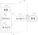
도 1은 환경을 공간적으로 프로파일링하기 위한 모듈을 도시한 것이다.
도 2는 광학 빔을 지향하기 위한 시스템의 배치를 개념적으로 도시한 것이다.
도 3a 및 도 3b는 광학 빔 지향기의 배치와 스윕 파장 채널들에 걸쳐 광학 빔의 공간 분포를 개념적으로 도시한 것이다.
도 4a 및 도 4b는 광학 빔 지향기의 다른 배치와 스윕 파장 채널들에 걸쳐 광학 빔의 공간 분포를 개념적으로 도시한 것이다.
도 5a 및 도 5b는 광학 빔 지향기의 또다른 배치와 스윕 파장 채널들에 걸쳐 광학 빔의 공간 분포를 개념적으로 도시한 것이다.
도 6a 및 도 6b는 광학 빔 지향기의 또다른 배치와 스윕 파장 채널들에 걸쳐 광학 빔의 공간 분포를 개념적으로 도시한 것이다.
도 7a 및 도 7b는 광학 빔 지향기의 또다른 배치와 스윕 파장 채널들에 걸쳐 광학 빔의 공간 분포를 개념적으로 도시한 것이다.
도 8은 광학 빔을 지향하는 시스템의 배치를 개념적으로 도시한 것이다.
도 9a 및 도 9b는 가변 선-간격 격자의 다른 배치를 도시한 것이다.
도 10a 및 도 10b는 제2 발산 요소의 배열의 다른 배치를 도시한 것이다.
도 10c는 제2 발산 요소의 배열의 또다른 배치를 도시한 것이다.
도 11은 도 8의 시스템의 차단된 출력의 이미지를 개념적으로 도시한 것이다.Figure 1 shows a module for spatially profiling an environment.
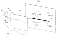
Figure 2 conceptually illustrates the arrangement of a system for directing an optical beam.
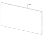
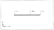
Figures 3A and 3B conceptually illustrate the arrangement of the optical beam deflector and the spatial distribution of the optical beam over the sweep wavelength channels.
Figures 4A and 4B conceptually show the spatial distribution of the optical beam over different arrangements of optical beam deflectors and sweep wavelength channels.
Figures 5A and 5B conceptually illustrate another arrangement of optical beam deflectors and spatial distribution of optical beams over sweep wavelength channels.
Figures 6A and 6B conceptually illustrate another arrangement of optical beam deflectors and spatial distribution of optical beams over sweep wavelength channels.
Figures 7A and 7B conceptually illustrate another arrangement of the optical beam deflectors and spatial distribution of the optical beam over the sweep wavelength channels.
Figure 8 conceptually illustrates the arrangement of a system for directing an optical beam.
Figures 9A and 9B illustrate different arrangements of variable line-spacing gratings.
10A and 10B show another arrangement of the arrangement of the second diverging elements.
Figure 10c shows yet another arrangement of the arrangement of the second diverging element.
Figure 11 conceptually illustrates an image of the blocked output of the system of Figure 8;
여기에 설명되는 것은 2개 차원에 걸쳐 빛을 지향하는 광학 시스템이다. 설명된 시스템은 하나 또는 그 이상의 선택된 파장 채널들에 기초하여 그리고 기계적으로 움직이는 부품 없이 빛을 조정하는 것이 가능하다. 여기의 설명이 단일 선택된 파장 채널(예컨대 단일 파장-가변 광원을 사용하여)에 초점을 맞추고 있다 하더라도, 그 설명은 작은 수정만으로 (예컨대, 다중-색상 광원이나 다중 단일-파장 가변 광원들의 조합을 사용함으로서) 다중 선택된 파장 채널들에 적용될 수 있음을 이해하여야 한다. 스캐닝 속력, 방향 안정성 및 공간 분해능의 관점에서 조작가능성(steerability)은 각각 파장-변경 속력, 파장 안정성과 파장-분해능에 따라 달라진다. 설명된 시스템은 기계적 성능에의 의존을 줄일 수 있어서 유용할 수 있으며, 예컨대 그 특성상 기계적 고장 또는 기계적 피로에 따른 발생 또는 충격을 줄일 수 있다.What is described here is an optical system that directs light over two dimensions. The described system is capable of adjusting light based on one or more selected wavelength channels and without mechanically moving parts. Although the description herein focuses on a single selected wavelength channel (e.g., using a single wavelength-variable light source), the description may be based only on small modifications (e.g., using a combination of multiple-color light sources or multiple single- It should be understood that the present invention can be applied to multiple selected wavelength channels. In terms of scanning speed, directional stability and spatial resolution, the steerability depends on the wavelength-changing speed, wavelength stability and wavelength-resolution, respectively. The described system may be useful as it may reduce reliance on mechanical performance and may reduce the occurrence or impact of mechanical failure or mechanical fatigue, for example due to its nature.
설명된 시스템은 빔 지향기로 사용될 수 있으며, 예컨대 환경의 공간적 프로파일을 추정하는 공간 프로파일링 배치에 사용될 수 있다. 빔 지향을 응용하는 다른 예시는 분광(spectrometry), 광학 시선 통신(optical line-of-sight communications), 제조 라인 상의 2D 스캐닝, 2D 프린터, 적응형 조명 등을 포함할다. 비록 뒤이은 설명이 공간 프로파일 추정에 초점을 맞추고 있지만, 당업자라면 그 설명이 작은 수정만으로, 다른 빔 지향 응용들에도 적용가능함을 이해할 수 있을 것이다.The described system can be used as a beam director and can be used, for example, in a spatial profiling arrangement to estimate the spatial profile of the environment. Other examples of beam-oriented applications include spectrometry, optical line-of-sight communications, 2D scanning on a manufacturing line, 2D printers, adaptive illumination, and the like. Although the following description focuses on spatial profile estimation, it will be understood by those skilled in the art that the description is applicable to other beam-oriented applications with only minor modifications.
도 1은 공간 프로파일링 배치(100)의 예시를 도시한 것이다. 배치(100A)는 광원(102), 빔 지향기(103), 광 수신기(104) 및 처리 유닛(105)을 포함한다. 도 1의 배치에서, 광원(102)으로부터 나오는 빛은 빔 지향기(103)에 의해 2개 차원 방향으로 지향되어 공간 프로파일을 가진 환경(110)으로 간다. 만약 나온 빛이 물체나 반사면에 부딪혔다면, 나가는 빛의 적어도 일부가 반사되어(직선 화살표로 표시됨), 그 물체나 반사면에 의해 예컨대 산란되어, 빔 지향기(103)로 되돌아와 광 수신기(104)에 수신된다. 처리 유닛(105)은 그 작동을 제어하기 위해 광원(102)과 작동상 결합된다. 처리 유닛(105)은 또한 반사광에 의해 지나친 왕복-여행의 거리를 판단함으로써 반사면과의 거리를 결정하기 위하 광 수신기(104)와 작동상 결합된다.FIG. 1 illustrates an example of a
광원(102), 빔 지향기(103), 광 수신기(104)는 자유-공간 광학 그리고/또한 2D나 3D 도파관들의 형태로 광섬유나 광회로와 같은 광학 도파관을 통해 서로 간에 광학적으로 결합될 수 있다. 광원(102)으로부터 나가는 빛은 환경으로 지향되기 위하여 빔 지향기(103)에 제공된다. 빔 지향기(103)에 의해 수집된 임의의 반사광은 광 수신기(104)로 지향될 수 있다. 일 실시예에서, 광원(102)으로부터의 빛은 또한 광원(102)으로부터 광 수신기(104)로의 직접 광 경로(도시되지 않음)를 통해 광학 처리 목적을 위한 광 수신기(104)에 제공될 수 있다. 예컨대, 광원(102)으로부터의 빛은 먼저 샘플러(예컨대 90/10 광섬유 커플러)에 진입하고, 거기서 대부분(예컨대 90%)의 빛이 빔 지향기(103)로 제공되고 남은 샘플 부분(예컨대 10%)의 빛은 직접 경로를 통해 광 수신기(104)로 제공될 수 있다. 다른 예시에서, 광원(102)으로부터의 빛은 처음에 광학 스위치의 입력 포트에 진입하고 두 개의 출력 포트들 중의 하나로부터 탈출할 수 있고, 여기서 한 출력 포트는 빛을 빔 지향기(103)로 다른 하나의 출력 포트는 빛을 처리 유닛(105)에 의해 결정된 시간에 광 수신기(104)로 재-지향시킬 수 있다.The
광원(102)으로부터의 빛은 M 파장 밴드들로 그룹지어지는 N개의 파장 채널들 중의 선택된 하나를 포함한다. 광원(102)은 파장-가변 레이저일 수 있는데, 원하는 파장 채널의 선택을 전기 제어 신호를 통해 가능케 한다. M개의 파장 밴드들은 연속적인 파장 채널들을 포함할 수 있다. 예컨대, N개의 파장 채널들은 그들의 중심 파장들 λ1, λ2, ... λN에 의해 지정될 수 있고, M개의 파장 밴드들은 {λ1, λ2, ... λk}, {λk+1, λk+2, ... λ2k}, ... {λN-k+1, λN-k+2, ... λN}이며 k = N/M이다.Light from the
< 제1 배치 ><First arrangement>
도 2를 참조하면, 설명되는 시스템(203)이 도 1에서 빔 지향기(103)의 역할을 한다. 설명되는 시스템(203)은 (선형 또는 비선형 차원일 수 있는) 초기 차원 너머로 광원(102)으로부터 빛(201)을 지향하도록 배치된 발산 요소(dispersive element)(202)를 포함한다. 발산 요소(202)는 하나 또는 그 이상의 격자(grating) 또는 하나 또는 그 이상의 프리즘일 수 있 있다. 비록 도 2에 도시된 초기 차원이 광 경로(210a)(예컨대 파장 채널 λ1에 대응되는)와 광 경로(210b)(예컨대 파잘 채널 λN에 대응되는) 사이의 연속 평면처럼 보인다 하더라도, 시스템(203)은 실제로는 일반적으로 다중 파장 채널들 중의 선택된 하나에 기초하여 임의의 한 시각에 파장 채널 λ1, λ2, ... λN 중의 선택된 하나만을 받아들인다.Referring to Fig. 2, the
설명되는 시스템(203)은 지향된 빛(210)을 수신하기 위해 초기 차원을 따라 배치된 (도 2에서 공동으로 (204)로 표시된) 반사 요소들(reflective elements)의 배열을 포함한다. 설명적인 목적에서, 설명되는 시스템(203)의 일부분이 아닌 스크린(208)이 도 2에 도시되어 선택된 파장이 λ1과 λN 사이를 쓸어갈 때 지향된 광학 빔(212)의 공간 분포를 묘사한다. 도 2에 도시된 것처럼, 반사 요소(204)가 단일 평면 거울의 형태를 취할 때, 지향된 빛(210)의 광 경로(210a)는 반사광(212)의 광 경로(212b)를 따라 반사된다. 유사하게, 지향된 빛(210)의 광 경로(210b)는 반사광(212)의 광 경로(212a)를 따라 반사된다. 단일 평면 거울의 경우에, 이미지(206)는 연속선의 형태를 띈다. 다시, 시스템(203)이 실제로는 일반적으로 임의의 한 시각에 파장 채널 λ1, λ2, ... λN 중의 선택된 하나를 받아들이며, 이미지(206)는 실제로는 설명적 목적을 위해 도 2에 묘사된 것처럼 연속선이라기 보다는 점(point)의 형태를 띈다. 지향된 광학 빔(206)의 공간 분포는 제1 차원(214)을 따르며, 제1 차원(214)은 발산 요소(202)에 의해 야기된 초기 차원과 연관된다. 지향된 광학 빔(206)은 제1 차원(214)에 실질적으로 수직인 제2 차원(216)을 따라 분포되지 않는다.The illustrated
도 3 내지 도 7은 다른 배열의 반사 요소들을 채용한 결과들을 도시한다. 도 3a 및 도 3b는 비교를 하기 위해 도 2의 단일 평면 거울의 경우를 재현한 것이다. 반사 요소(204)가 단일 평면 거울(304)인 경우에, 이미지(206)는 선택된 파장이 λ1과 λN 사이를 쓸어가는 연속선(306)의 형태이다. 지향된 광학 빔(212)의 공간 분포는 제1 차원(214)을 따르며, 제1 차원(214)은 발산 요소(202)에 의해 야기된 초기 차원과 연관된다. 지향된 광학 빔(206)은 제2 차원(216)을 따라 분포되지 않는다.Figures 3-7 illustrate the results of employing different arrangements of reflective elements. FIGS. 3A and 3B are reproductions of the case of the single plane mirror of FIG. 2 for comparison. When the
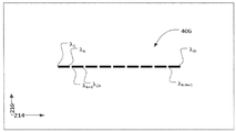
도 4a 및 도 4b는 반사 요소들(204)이 단일 평면 거울(404)의 배열이고 각 단일 평면 거울(404)들이 인접한 거울들로부터 작은 틈만큼 분리된 경우를 나타낸다. 이미지(206)는 선택된 파장이 λ1과 λN 사이를 쓸어가는 파선(406)의 형태이다. 파선의 각각의 잘린 부분은 파장 채널들의 밴드를 가로지르는 파장 스윕(sweep)을 나타낸다(예컨대 {λ1, λ2, ... λk}, {λk+1, λk+2, ... λ2k}, ... {λN-k+1, λN-k+2, ... λN}). 이 경우에, 지향된 광학 빔(212)의 공간 분포는 여전히 제1 차원(214)을 따르며, 발산 요소(202)에 의해 야기되는 초기 차원과 연관된다. 지향된 광학 빔(206)은 제2 차원(216)을 따라 분포되지 않는다.Figures 4A and 4B show the case where
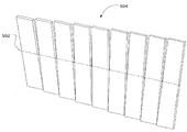
도 5a 및 도 5b는 반사 요소들(204)이 평면 거울들의 배열(504)이고, 각 평면 거울들은 인접한 거울들로부터 작은 틈만큼 분리되어 있으며, 각각의 평면 거울들을 통과해 제1 차원(214)을 따라 연장하는 직선축(502) 주위로 기울어지거나 아니면 서로 각도방향으로 오프셋된 설명되는 시스템(203)의 구성을 나타낸다. 이미지(206)는 선택된 파장이 λ1과 λN 사이를 쓸어가는 계단 선들(506)의 형태이다. 각 계단은 파장 채널들의 밴드를 가로지르는 파장 스윕을 나타낸다(예컨대 {λ1, λ2, ... λk}, {λk+1, λk+2, ... λ2k}, ... {λN-k+1, λN-k+2, ... λN}). 각도 오프셋의 효과는 수신된 빛(212)을 제2 차원(216)에 걸쳐 분포된 실질적으로 평탄한 상이한 표면들(또는 여기서는 "평면"들)로 반사한다는 것이며, 여기서 각 평면은 제1 차원(214)을 가로질러 확장한다. 지향된 광학 빔(206)은 제1 차원(214)과 제2 차원(216) 양쪽을 따라 분포한다. 그러나 상이한 평면들의 정도는 제1 차원(214)에서 겹치지 않는다. 도시되지는 않았으나, 상이한 평면들은 평면 거울들(504)이 더 기울어지거나 아니면 축(502)에 수직이고 제2 차원(216)을 따라 연장하는 축 주위로 서로 간에 더 각도진 경우에 적어도 부분적으로 겹치도록 구성될 수 있다. 이미지(206) 상의 이 수직 기울어짐의 효과는 제1 차원(214)을 따라 단계진 선들(506)로 옮겨진다. 각 평면 거울(504)에 대한 적당한 양의 수직 기울어짐은 단계진 선들을 서로 간에 완전히 겹치도록 옮길 수 있으며, 2차원 스티어링 그리드를 형성한다.5A and 5B show that the
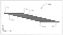
도 6a 및 도 6b는 반사 요소들(204)이 발산하는 거울의 배열(504)(반사형 원통이나 볼록한 표면의 형태로)이고, 각 발산 거울들은 인접한 거울과 작은 틈만큼 분리되어 있으며, 각각의 발산 거울들의 중심을 통과해 직선축(602) 주위로 기울어지거나 아니면 서로 각도방향으로 오프셋된 설명되는 시스템(203)의 배치를 나타낸다. 이미지(206)는 선택된 파장이 λ1과 λN 사이를 쓸어가는 계단 선들(606)의 형태이다. 각 계단은 파장 채널들의 밴드를 가로지르는 파장 스윕을 나타낸다(예컨대 {λ1, λ2, ... λk}, {λk+1, λk+2, ... λ2k}, ... {λN-k+1, λN-k+2, ... λN}). 도 5a 및 도 5b에 도시된 경우와 같이, 각도상 오프셋의 효과는 수신된 빛(212)을 제2 차원(216)에 걸쳐 분포된 상이한 평면들로 반사하는 것이며, 거기서 각 평면은 제1 차원(214)을 가로질러 확장된다. 발산 거울들의 사용은 제1 차원(214)에서 각 평면의 범위를 확장하는 것이며, 이것은 상이한 곡률을 가진 발산 거울들을 사용함으로써 제어될 수 있다. 일반적으로, 더 큰 곡률의 발산 거울들은 제1 차원(214)을 따라 확장하는 더 큰 범위의 평면들을 이끌어낸다. 지향된 광학 빔(206)은 제1 평면(214)과 제2 평면(216) 모두를 따라 분포된다.Figures 6a and 6b show an array of mirrors 504 (in the form of reflective cylinders or convex surfaces) from which the
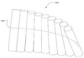
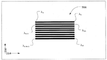
도 7a 및 7b는 반사 요소들(204)이 발산 거울들의 배열(704)(반사형 원통이나 볼록한 표면의 형태로)이고, 각 발산 거울들은 인접한 거울과 작은 틈만큼 분리되어 있으며, 기울어지거나 아니면 서로 각도방향으로 오프셋되고, 각각의 반사 요소들을 통해 곡선축(702) 중심으로 배치된, 설명되는 시스템(203)의 배치를 나타낸다. 이미지(206)는 선택된 파장이 λ1과 λN 사이를 쓸어가는 스택 선들(stack lines)(706)의 형태이다. 각각의 스택(stack)은 파장 채널들의 밴드를 가로지르는 파장 스윕을 나타낸다(예컨대 {λ1, λ2, ... λk}, {λk+1, λk+2, ... λ2k}, ... {λN-k+1, λN-k+2, ... λN}). 도 5a 및 도 5b에 도시된 경우와 같이, 각도상 오프셋의 효과는 수신된 빛(212)을 제2 차원(216)에 걸쳐 분포된 상이한 평면들로 반사하는 것이며, 거기서 각 평면은 제1 차원(214)을 가로질러 확장된다. 각도상 오프셋은 스택들의 분리를 조절하기 위해 가변될 수 있다. 발산 거울들의 사용은 제1 차원(214)에서 각 평면의 범위를 확장하는 것이며, 이것은 상이한 곡률을 가진 발산 거울들을 사용함으로써 제어될 수 있다. 일반적으로, 더 큰 곡률의 발산 거울들은 제1 차원(214)을 따라 확장하는 더 큰 범위의 평면들을 이끌어낸다. 한 배치에서, 곡선 축(702)은 각각의 평면을 가로질러 제1 차원(214)의 범위를 균등화(equalising)하거나 정렬(aligning)하는 초기 차원에서의 오목한 경로를 따른다. 다른 배치에서, 곡선 축은 포물선일 수 있다. 곡선 축(702)의 곡률은 각각의 평면을 가로질러 범위를 조절하도록 가변될 수 있다. 지향된 광학 빔(206)은 제1 평면(214)과 제2 평면(216) 모두를 따라 분포된다.7A and 7B show that the
도 7a의 배치를 사용하면, 설명되는 시스템(203)은 나가는 빛을 2개 차원(214, 216)에서 환경(110)으로 다중 방향들(106a, 106b, 106c, ...) 중의 하나로 공간적으로 지향하도록 구성될 수 있다. 나가는 빛이 지향되는 방향은 다중 파장 채널들(λ1, λ2, ... λN 에 중심을 둔) 중의 선택된 하나에 대응하거나 기초한다.Using the arrangement of FIG. 7A, the described
< 예시 ><Example>
한 구성에서, 다중 스펙트럼 성분이나 가변가능한 파장(예컨대 가변가능한 레이저 C-밴드 43nm 튜닝 범위)을 가진 광원이 프리즘이나 복합 프리즘과 같은 회절 요소에 입사하거나 투과하며, 이것은 파장 채널의 선택을 1차원 상의 각 발산으로 바꾼다. 이 구성에서, 0.25도/mm의 각 분산을 제공하는 프리즘은 43nm 스펙트럼 범위를 10도의 각 분리로 변환한다. 이 구성은 각방향으로 분산된 빛을 확대하기 위한 확대 망원경(예컨대 15배)이나 볼록 거울(예컨대 반원형)을 포함한다. 15배 확대 망원경을 사용하여, 각 분산은 약 150도로 확대된다. 각 확대기의 출력은 오목 거울의 곡률 중심에 위치하도록 배치되어, 출력광이 볼록 거울의 반경을 따라 지향된다. 이 경우에 입사 빔들은 진행 방향이 거울 표면에 수직이기 때문에 그들이 거울 표면에 입사함에 따라 동일하지만 반대 방향으로 반사될 것이다.In one configuration, a light source having a multispectral component or a variable wavelength (e.g. tunable laser C-band 43 nm tuning range) is incident or transmitted through a diffractive element such as a prism or a composite prism, We change to each divergence. In this configuration, a prism that provides an angular dispersion of 0.25 degrees / mm converts the 43 nm spectral range into a 10 degree angular separation. This configuration includes an enlarged telescope (e.g., 15 times) or a convex mirror (e.g., a semi-circular) for magnifying light scattered in each direction. Using a 15x magnification telescope, each dispersion is magnified by about 150 degrees. The output of each magnifier is arranged to be located at the center of curvature of the concave mirror so that output light is directed along the radius of the convex mirror. In this case, the incident beams will be reflected in the same but opposite direction as they are incident on the mirror surface because the direction of travel is perpendicular to the mirror surface.
이 구성에서, 볼록 거울의 반경이 0.05m라고 가정하면, 입사광에 의해 조광되는 150도를 커버하는 것은 호(arc)는 0.13m이다(0.05 × π × 150도/180도). 일 예시에서, 이 0.13m의 호는 50개의 하위-부분들로 분할되고, 각 부분은 0.0013m 반경의 반원 볼록 거울을 위치하도록 구성된다. 50개의 볼록 반원들 각각에 입사하는 빛은 3도 각도(즉, 150도/50)에 면하겠지만, 작은 반원들은 각도 확대 효과를 가지게 될 것이어서 각 하위-부분에서 반사된 빛은 3도 × 38.19 = 114.59의 각 분산을 가질 것인데, 38.19의 확대는 반지름 비율로부터 얻어진 것이다(즉, 0.05/0.0013 = 38.19배).In this configuration, assuming that the radius of the convex mirror is 0.05 m, the arc is 0.13 m (0.05 x pi x 150 degrees / 180 degrees) to cover the 150 degrees illuminated by the incident light. In one example, this 0.13 m arc is divided into 50 sub-portions, each of which is configured to position a semi-convex mirror with a radius of 0.0013 m. The light incident on each of the 50 convex semicircles will be at a 3 degree angle (ie 150 degrees / 50), but the small semicircles will have an angular magnification effect so that the light reflected from each sub- 114.59, and the magnification of 38.19 is obtained from the radius ratio (i.e., 0.05 / 0.0013 = 38.19 times).
그 후 이 구성은 도 7a를 따라 배치될 수 있다. 각각의 이들 작은 볼록 반원들은 관형 섹션으로 구성된다. 각각의 관형 섹션을 이전 섹션에 대하여 Z축으로 0.5도 기울임으로써 각각의 반사광은 상이한 z축 각 분산 상에 (0.5도 증분을 가지고) 투사된다. 반사광은 파장 채널에 기초한 2D 이미지를 생성한다. 이 예시에서 2D 이미지는 수직으로 50개 선들을 0.5도 해상도로 그리고 수직 시야 25도(50 × 0.5도)로 포함한다. 예시적 구성은 수평으로 114.59도를 커버하며 광원의 파장에서의 최소 변화에 의해 제한되는 해상도를 가진다.This configuration can then be arranged according to FIG. 7A. Each of these small convex semicircles consists of a tubular section. By tilting each tubular section by 0.5 degrees in the Z-axis relative to the previous section, each reflected light is projected (with a 0.5 degree increment) onto a different z-axis angular dispersion phase. The reflected light produces a 2D image based on the wavelength channel. In this example, the 2D image includes fifty lines vertically at a resolution of 0.5 degrees and a vertical field of view at 25 degrees (50 x 0.5 degrees). The exemplary configuration covers 114.59 degrees horizontally and has a resolution limited by a minimum change in wavelength of the light source.
앞선 설명에 기초하여, 빛을 2개 차원으로 지향시키는 광학 시스템이 제공된다. 빛은 파장 밴드들로 그룹지어지는 다중 파장 채널들 중의 선택된 하나를 포함한다. 시스템은 다중 파장 채널들 중의 선택된 하나에 기초하여 초기 차원에 걸쳐 빛을 지향하도록 배치된 발산 요소를 포함하며, 지향된 빛을 수신하기 위하여 초기 차원을 따라 배치된 반사 요소들의 배열을 포함하며, 반사 요소들은 수신된 빛을 각각의 파장 밴드들에 기초하여 각각의 평면들에 반사하도록 배치되고, 각각의 평면들은 초기 차원과 연관된 제1 차원을 가로질러 확장하고, 각각의 평면들은 제1 차원에 실질적으로 수직인 제2 차원에 걸쳐 분포된다.Based on the foregoing description, an optical system for directing light to two dimensions is provided. The light comprises a selected one of the multiple wavelength channels grouped into the wavelength bands. The system includes a diverging element arranged to direct light over an initial dimension based on a selected one of the multiple wavelength channels and includes an array of reflective elements disposed along an initial dimension to receive the directed light, The elements are arranged to reflect the received light on each of the planes based on respective wavelength bands, each of the planes extending across a first dimension associated with an initial dimension, Which is perpendicular to the second dimension.
빛을 2개 차원들에 걸쳐 지향하는 대응하는 방법도 제공된다. 방법은 발산 요소를 사용하여, 다중 파장 채널들 중의 선택된 하나에 기초하여 초기 차원을 따라 배치된 반사 요소들의 배열에 초기 차원에 걸쳐, 빛을 지향하고, 반사 요소들의 배열을 사용하여, 각각의 파장 밴드들에 기초한 각각의 평면들을 향해 지향된 빛을 반사하고, 각각의 평면은 초기 차원과 연관된 제1 차원을 가로질러 확장하고, 각각의 평면들은 제1 차원에 실질적으로 수직인 제2 차원에 걸쳐 분포된다.A corresponding method of directing light across two dimensions is also provided. The method uses a divergent element to direct light over an initial dimension to an array of reflective elements disposed along an initial dimension based on a selected one of the multiple wavelength channels, Each of the planes extending across a first dimension associated with an initial dimension and each of the planes extending across a second dimension substantially perpendicular to the first dimension .
< 제2 배치 >≪ Second arrangement >
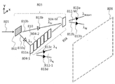
도 8을 참조하면, 설명되는 시스템(803)은 도 1의 빔 지향기(103)의 역할을 수행한다. 설명되는 시스템(803)은 빛(801)을 광원(102)으로부터 초기 차원에 걸친 제1 방향들 중의 하나를 향해 (예컨대 도 8의 X축을 따라) 지향시키도록 배치된 제1 발산 요소(802)를 포함한다. 각각의 제1 방향들은 지향된 빛(810)의 잠재적인 광 경로에 대응하며, 다시 파장 채널에 대응한다. 예컨대, 도 8에 도시된 것처럼, 광 경로(810a)는 파장 채널 λ1에 대응하고 광 경로(810b)는 파장 채널 λN에 대응한다. 제1 방향들 중의 일부는 도 8에서 열린 삼각형 (811a)와 (811b)로 제시된다. 제1 발산 요소(802)는 하나 또는 그 이상의 분산 격자들 및/또는 하나 또는 그 이상의 프리즘들일 수 있다. 지향된 빛(810)의 각 확산(angular spread)은 파장 채널들의 범위와 발산 요소(802)의 분산 특성에 의존한다. 하나의 비-한정적 예시로서 설명적인 목적에서, 광원(102)은 원거리통신-등급 레이저(telecommunications-grade laser)를 포함할 수 있다. 원거리통신-등급 레이저는 40nm에 이르는 범위의 가변적인 파장을 가질 수 있는데, 예컨대 약 1527nm로부터 약 1567nm까지이다. 발산 요소(802)는 균일한 선 간격을 가지는 (전송 격자와 같은) 회절 격자를 포함할 수 있다. 한가지 변형에서, 회절 격자는 1000라인/mm 내지 1100라인/mm 사이의 격자 주기를 가질 수 있고, 약 5~10도의 각 분산을 용이하게 한다. 다른 변형에서, 회절 격자는 600라인/mm의 격자 주기를 가질 수 있다.Referring to FIG. 8, the described
설명되는 시스템(803)은 지향된 빛(810)을 수신하기 위한 초기 차원을 따라 배치된 제2 발산 요소(804-1, ... 804-M)(모아서 (204)로 지칭됨)의 배열을 포함한다. 이 예시에서, M개의 제2 발산 요소들이 있고, M개의 파장 밴드들에 대응한다. 제2 발산 요소들의 배열은 수신된 빛을 제2 방향들 중의 하나를 향해 지향하도록 더 구성된다. 전체는 아닌 일부 제2 방향들이 도 8에서 폐삼각형 813a, 813b, 813c 및 813d로 표현된다. 도 8에 도시된 것처럼, 제2 방향들은 각각의 파장 밴드들에 기초한 각각 실질적으로 평탄한 평면(또는 여기서는 "평면")을 따라 정렬된다. 예컨대, 발산 요소(804-1)를 향해 지향된 파장 채널들 {λ1, λ2, ... λk}에서의 빛은 배열(804)(특히 발산 요소 (804-1))에 의해 M개의 파장 밴드들 중의 첫번째에 대응하는 가장 좌측의 평면(812-1)을 따라 정렬된 방향들을 향해 더 지향된다. 유사하게, 도시되지는 않았으나, 발산 요소(804-2)를 향해 지향된 파장 채널들 {λk+1, λk+2, ... λ2k}에서의 빛은 배열(804)(특히 발산 요소(804-2))에 의해 M개의 파장 밴드들 중의 두번째에 대응하는 평면을 따라 정렬된 방향들을 향해 더 지향되고, 계속되어, 발산 요소(804-M)을 향해 지향된 파장 채널들 {λN-k+1, λN-k+2, ... λN}에서의 빛은 배열(804)(특히 발산 요소(804-M))에 의해 M개의 파장 밴드들 중의 M번째에 대응하는 가장 우측의 평면을 따라 정렬된 방향들을 향해 지향된다.The described
실제로는, 시스템(803)은 출력 빔으로서 지향되는 빛의 평면을 낳지 않는다. 오히려, 각각이 대응되는 중심 파장과 연관되는, 빛의 하나 또는 몇몇 빔들이 임의의 한 시각에 출력 빔으로서 지향된다. 도 8에서 평면 표현은 설명적인 목적을 위해 묘사된 것일 뿐이다. 즉, 도 8에 묘사된 지향된 빛(810)이 (예컨대 파장 채널 λ1에 대응하는) 광 경로(810a)와 (예컨대 파장 채널 λN에 대응하는) 광 경로(810b) 사이의 초기 차원에서 연속 평면으로서 나타나고, 도 8에 묘사된 더 지향된 빛(812)이 연속 평면들(812-1, ... 812-M)로 나타나는 반면, 시스템(803)은 일반적으로 임의의 한 시각에 파장 채널 λ1, λ2, ... λN 중의 선택된 하나를 받아들인다. 대안적으로, 도 8의 평면 표현은 λ1로부터 λN로 빠른 파장 스캔을 캡춰하는 것으로 보여질 수 있다.In practice, the
게다가, 비록 시스템(803)이 단일한 선택된 파장 채널을 사용하여 설명되었지만, 당업자라면 시스템이 동시에 또는 거의 동시에 파장 채널들 중의 선택된 몇몇 개를 받아들이도록 구성될 수 있음을 이해할 것이다. 일 예시에서, 광원(102)은 다중의 파장-가변 레이저를 포함하며, 각각은 상이한 파장을 방출하도록 조율될 수 있다.In addition, although
설명적인 목적에서, 설명되는 시스템(803)의 일부가 아닌 스크린(808)이 도 8에 묘사되어 선택된 파장이 λ1과 λN 사이를 휩쓸 때 출력 광학 빔(812)의 공간 분포(1000)(도 10과 이하의 설명을 보라)를 묘사하고 있다. 제2 발산 요소들(804)의 배열은 각각이 개별적인 제2 발산 요소(804) 내에서 빛이 입사하는 위치에 따른 제2 방향들 중의 하나를 향해 수신된 빛을 지향시키도록 구성된다. 배열은 설명적인 목적에서 도 8에서 분리된 발산 요소들(804)을 가진 것으로 묘사된다. 발산 요소들(804)은 도시된 것처럼 선들과 함께 틈에 의해 분리되거나 분리되지 않을 수 있다.In the illustrative purposes, describe the spatial distribution of the
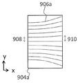
한가지 배치에서, 제2 발산 요소(804)의 배열은 각각이 제2 차원을 가로질러 수신된 빛을 회절시키기 위한 (투과에서와 같은) 가변 선-간격 격자(variable line-spacing grating)를 포함한다. 가변 선-간격 격자는 가변 선-간격 격자 상의 초기 차원을 따른 (예컨대 X축을 따른) 위치들에 기초한 다중 격자 주기들을 포함한다. 한가지 배치에서, 가변 선-간격 격자(904a)는 제1 에지에서 더 짧은 격자 주기(908)를 가지고 반대편 제2 에지에서 더 긴 격자 주기(910)를 가진다. 격자 주기는 제1 에지로부터 제2 에지로 가면서 증가할 수 있다. 한가지 배치에서, 다중 격자 주기의 가변은 제2 발산 요소들의 배열(804)을 가로지르면서 실질적으로 반복된다. 달리 말하면, 격자 주기는 제2 발산 요소들 각각의 제1 에지로부터 제2 에지로 가면서 증가할 수 있다.In one arrangement, the arrangement of the second
도 9a 및 도 9b는 가변 선-간격 격자의 두가지 배치를 도시한 것이다. 도 9a의 배치에서, 격자 주기는 제1 에지에서 제2 에지로 가면서 (예컨대 1060라인/mm의 라인 간격으로) 연속적으로 변화한다. 다중 격자 주기들에서의 연속적인 가변은 부드러운 격자 선들(906a)을 드러낸다. 이 배치의 예시에서, 제1 에지에서의 선 간격(908)은 800라인/mm인 반면 제2 에지에서의 선 간격(910)은 1050라인/mm이다. 파장에 변화가 없음에도 불구하고, 그러한 선 간격의 범위는 약 30~35도의 빔 분산을 야기하기에 충분하다. 다른 선 간격이 사용될 수 있다. 배열은 40mm 길이일 수 있다. 이 예시에서, 가변 선-간격 격자 각각의 폭은(즉, 제1 에지로부터 제2 에지로의 거리)는 1mm일 수 있으며, 따라서 배열(804) 내에서 약 40개의 발산 요소들을 허용한다.Figures 9a and 9b show two arrangements of variable line-spacing gratings. In the arrangement of FIG. 9A, the grating period changes continuously from the first edge to the second edge (e.g., with a line spacing of 1060 lines / mm). Continuous variables in multiple grid periods reveal
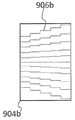
격자의 길이는 20mm일 수 있고, 따라서 적어도 18000개의 격자선들을 허용할 수 있다. 도 9b의 배치에서, 격자주는 제1 에지에서 제2 에지로 가면서 이산적으로(discretely) 변화한다. 다중 격자 주기에서의 이산 가변은 계단형 격자선(906b)을 드러낸다. 설명적인 목적에서만, X축을 따른 계단들은 Y축을 따른 선들과 연결되어 있으나, 실제로는 Y축을 따른 격자 선들이 없을 수 있다는 것을 유의해야 한다.The length of the grating can be 20 mm, thus allowing at least 18000 grating lines. In the arrangement of FIG. 9B, the grating period changes discretely from the first edge to the second edge. The discrete variable in the multiple grating period exposes the stepped grating 906b. Note that for illustrative purposes only, the steps along the X axis are connected to the lines along the Y axis, but in practice there may be no grid lines along the Y axis.
연속적인 가변 선-간격 격자가 사용될 때, 도 9a에서 처럼, 시스템(903)은 초기 차원에서 가변 선-간격 격자들에서 수신된 빛을 가두는(예컨대, 초점을 맞추는) 포커싱 요소(focussing element)(도시되지 않음)를 더 포함할 수 있다. 초점 작용은 초기 차원을 따른 광 빔의 공간적 범위를 유지하여 적절하게 균일하게 간격지어진 격자들을 보거나 조광하기에 충분할 만큼 작게 유지하는 것을 목표로 한다. 한가지 예시에서, 포커싱 요소는 초기 차원으로 굽어진(즉, X축을 따른) 원통형 렌즈이다. 빛이 포커싱 요소에 의해 포커싱되고 가변 선-간격 격자에서 수신되었을 때 가두어진 후에, 가변 선-간격 격자로부터 나온 빛은 발산할 수 있고 시준(collimation)을 요할 수 있다. 한가지 배치에서, 시스템(803)은 포커싱된 빛을 시준하기 위한 시준 요소를 포함한다. 시스템(803)이 시준된 빛을 형성, 지향, 필터 또는 다른 영향을 주기 위한 추가적인 광학 요소들을 포함할 수 있으나, 시준된 빛은 최종적으로는 환경(110)에 지향된다.When a continuous variable line-spacing grating is used, as in FIG. 9A, the system 903 includes a focussing element that confines (e.g., focuses) the received light in the variable line-spacing grids at an initial dimension, (Not shown). The focus is aimed to maintain the spatial extent of the light beam along the initial dimension to keep adequately uniformly spaced gratings small enough to view or illuminate. In one example, the focusing element is a cylindrical lens that is curved to an initial dimension (i.e., along the X axis). After the light is focused by the focusing element and received when received in a variable line-spacing grating, the light from the variable line-spacing grating may diverge and may require collimation. In one arrangement, the
대안적인 배치에서, 제2 발산 요소들은 각각 도 9a나 도 9b에서의 가변 선-간격 격자로서 기능하는 위치-의존적인 반사 요소를 포함할 수 있다. 제1 구성에서, 도 9b의 이상적인 가변-선 간격 격자와 유사하게, 각각의 발산 요소(804-X)는 반사 요소들의 집합(예컨대 평면 거울이나 MEM들)을 포함하며, 각각의 반사 요소는 초기 차원을 따라 위치되고 제2 방향에 대해 빛을 반사하도록 배치된다. 예컨대, 이 대안적인 배치를 제공하기 위하여, 도 9b에서 이산적인 가변 선-간격 격자의 각 부분으로서 수신된 빛에 의해 보여지고 국부적인 그리고 균일한 격자 주기를 가진 것은 제1 분산 요소로부터 평면들 812-1, 812-2, ... 812-M 중의 대응하는 평면을 따라 정렬된 각각의 방향으로 빛을 반사하는 각도로 평면 거울에 의해 대체될 수 있고, 각각의 방향은 초기 차원을 따른 각각의 평면 거울의 위치와 연관된다. 제2 구성에서, 도 9a의 연속적인 가변 선-간격 격자와 유사하게, 제1 구성의 반사 요소들의 집합은 곡면형 반사 평면으로 통합되어 형성될 수 있다. 달리 말하면, 이 대안적인 배치의 두가지 구성들 모두는 가변 선-간격 격자의 각각의 부분에 따라 동일한 지향 효과를 달성한다. 엄격하게 말하면 반사 요소 혼자만으로는 이 대안적인 배치에서 빛을 파장에 기초하여 지향하지 않지만, 그들은 제1 발산 요소와 공간적으로-의존하는 반사각으로부터 초기 발산의 수집 효과에 기초하여 제2 발산 요소들의 전체적인 발산 효과를 달성한다. 달리 말하면, 반사 요소들의 배열이 그들 스스로는 발산하지 않는다고 하더라도, 각각이 상이한 파장 채널들을 수신하고 수신된 빛을 반사하기 위하여 서로 다른 각도로 각도진 반사 요소들은 제2 발산 요소의 기능을 달성하는 것으로 여겨지며, 반사 요소들이 파장을 다루는 것이 가능한 조절을 제공한다.In an alternative arrangement, the second divergent elements may each include a position-dependent reflective element that functions as a variable line-spacing grating in Figs. 9a and 9b, respectively. In a first configuration, similar to the ideal variable-line spacing grating of FIG. 9B, each diverging element 804-X includes a set of reflective elements (e.g., planar mirrors or MEMs) Dimension and is arranged to reflect light in a second direction. For example, in order to provide this alternative arrangement, it can be seen from FIG. 9b that each part of the discrete variable line-spacing grating, viewed by the received light and having a local and uniform grating period, May be replaced by a planar mirror at an angle reflecting light in each direction aligned along a corresponding plane of the first, second, third, fourth, fifth, sixth, seventh, eighth, It is associated with the position of the plane mirror. In a second configuration, similar to the continuous variable line-spacing grating of FIG. 9A, the set of reflective elements of the first configuration may be formed integrally with a curved reflective surface. In other words, both of the two configurations of this alternative arrangement achieve the same directional effect according to each part of the variable line-spacing grating. Strictly speaking, the reflective elements alone do not direct light on a wavelength basis in this alternative arrangement, but they are based on the collecting effect of the initial divergence from the first divergent factor and the spatially-dependent reflection angle, Effect. In other words, even though the arrangement of the reflective elements themselves does not radiate, the reflective elements, which are each angled at different angles to receive the different wavelength channels and reflect the received light, achieve the function of the second divergent element And provides the possible adjustment that the reflective elements can handle the wavelength.
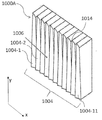
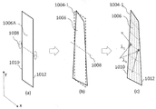
도 10a는 그러한 대안적인 배치에서의 제2 구성(1000A)을 도시한 것이다. 구성 (1000A)는 제2 발산 요소들(이 도시에서 1004-1, 1004-2, ... 1004-11)의 배열(1004)을 포함하며, 각각은 곡면형 반사 표면(1006)을 포함한다. 도 10b에 개념적으로 도시되었듯이, 각각의 제2 발산 요소(예컨대 1004-1)의 곡면형 반사 표면(1006)은 평면 (1006A)를 x-y 평면에서 X축에 평행한 축(1008) 주위로 "비트는" 것에 의해 형성된다고 이해될 수 있다. 예컨대, 도 10b의 (a) 및 (b)를 참조하면, 평평한 반사 표면 (1006A)에서 출발하여, 요소(1004-1)의 제1 에지(1010)가 축(1008) 주위로 한 방향으로(예컨대 시계방향) 변형되도록 회전되고 한편 요소(1004-1)의 제2의 그리고 반대 에지(1012)는 축(1008) 주위로 반대 방향으로(예컨대 반시계방향) 변형되도록 회전된다. 실제로는, 곡면(1006)의 형성은 변형에 의하지 않을 수 있고, 그러나 예컨대 고정밀 밀링(milling)에 이어 표면 폴리싱과 코팅(예컨대 금으로)에 의해 형성될 수 있다.Figure 10A shows a
도 10b의 (c)를 참조하면, 결과적인 표면 윤곽을 파선으로 보여주고 있으며, 제1 발산 요소(802)에 의해 지향되고 제1 에지(1010) 근처에 입사된 빛(도 10b의 (c)에서 λ1)은 한쪽 y-방향을 향해 반사되고(예컨대 양의 y-방향), 반면 제1 발산 요소(802)에 의해 지향되고 제2 에지(1012) 근처에 입사된 빛(도 10b에서 λk)은 다른 y-방향을 향해 반사된다(예컨대 음의 y-방향). 달리 말하면, 반사 표면의 법선 벡터는 X축을 따른 위치들에 기초하여 변화한다. 법선 벡터의 변화는 위치에 따라 연속적이거나 이산적일 수 있다. X축을 따라 위치된 각각의 추가적인 제2 발산 요소(1004-X)는 유사하게 제1 에지와 제2 에지가 반대 방향으로 "비틀어진" 것이 되도록 구성되며, 파장이 변화함에 따라 래스터 빔 스티어링(raster beam steering)을 용이하게 한다. 예컨대, 파장 밴드 λ1 에서 λk 내에서 파장이 변화함에 따라(즉 하나의 제2 발산 요소를 가로질러 입사할 때) 빛은 양의 y-방향으로부터 음의 y-방향으로 휩쓸고, 빛의 파장이 다음 파장 밴드 λk+1 에서 λ2k 로 변화함에 따라(즉, 다음 제2 발산 요소로 입사할 때) X축을 따라 계단이 지고, 계속된다. 언급한 바 있듯이, 한가지 구성에서, 각각의 제2 발산 요소(1004-X)의 곡면(1006)은 대안적으로 평면 반사 요소의 집합에 의해 형성될 수 있는데, 각각이 예컨대 양의 y-방향에서 음의 y-방향으로 점증하는 각도로 빛을 반사하도록 하는 것이다.10B, the resulting surface contour is shown in dashed lines and the light directed by the first diverging
도 10a의 배치(1000a)에서, 인접한 발산 요소들(1004-X) 사이의 경계에 갑작스러운 계단이 존재한다. 여기서, 갑작스런 계단(abrupt step)은 x-y 평면에 수직하고, 인접한 발산 요소(1004-X)의 곡면(1006)과 인접하는 인접 평면(1014)을 포함한다. 도 10c에 도시된 대안적인 배치(1000C)에서, 갑작스런 계단은 x-방향으로 지그-재그 형상을 드러낸다. 여기서, 인접 표면(1014C)은 입사광을 수신하는 곡면(1006C)의 거울상이다. 재치(1000C)의 상단부(1018)와 하단부(1020)를 따른 지그-재그 패턴은 서로 간에 반전된 버전들이다. 도 11은 나가는 빛을 잡기 위해 시스템(803)의 출력에 위치된 스크린(808)의 이미지(1100)를 개념적으로 도시한 것이다. 도 11의 각각의 점은 파장 채널들 λ1, λ2, ... λN 중의 선택된 하나를 나타낸다. 각각의 점들은 실제로는 선택된 파장 채널에 기초하여 독자적으로 나타나지만, 도시를 하기 위한 목적에서 모든 점들이 도 11에 마치 그들이 동시에 캡춰될 수 있다는 듯이 묘사되었다. 이미지(1100)는 빛 출력의 M개의 그룹들(1102-1, 1102-2 ... 1102-M)을 표시한다. M개 그룹의 빛 출력은 M개의 제2 발산 요소들(804-1 ... M), M개의 파장 밴드들 및 M개의 평면들(812-1 ... M)에 대응된다. 이 평면들은 제1 차원에 걸쳐 분포되고, 각각은 제1 차원에 실질적으로 수직인 제2 차원을 가로질러 확장한다. 제1 차원은 초기 차원(즉, 도 8의 X축)과 반드시 정확하게 일치하지 않을 수도 있고, 제2 차원은 초기 차원에 수직인 차원(즉, 도 8의 Y축)과 반드시 정확하게 일치하지 않을 수도 있다. 도 11에 도시된 것처럼, 광 출력의 각 그룹은 Y축으로부터 작은 각도로 기울어진 것으로 표현된다. 이 작은 각도의 기울어짐은 제1 발산 요소(202)에 의해 생성되고, 제2차원에서 위치-의존적인 발산을 제공하기 위해 각각의 제2 발산 요소의 초기 차원을 따라 상이한 위치들을 조광하기 위해 요구되는 작은 파장-의존적인 발산으로부터 유래하는 것이다. 이 기울어짐은 실제로는 무시할만한 수준이고 그리고/또는 쉽게 보정하거나 적응가능하며, 예컨대 물리적으로 장착 각도를 조절함으로써 평면들(812-1, 812-2 ... 812-M)이 물리적 세계 프레임에서의 진짜 수직축(즉, 자오선)에 정렬되도록 할 수 있다.In arrangement 1000a of FIG. 10a, there is a sudden step at the boundary between adjacent diverging elements 1004-X. Here, an abrupt step includes a
도 8의 배치를 사용하면, 설명되는 시스템(803)은 출력광을 2개 차원들(814 및 816)에서 다중 방향들(106a, 106b, 106c, ...) 중의 하나로 공간적으로 지향하여 환경(110)으로 보내게 된다. 출력광이 지향되는 방향은, (λ1, λ2, ... λN에 중심을 둔) 다중 파장 채널들 중의 선택된 하나에 대응하거나 기초한다.8, the described
< 일반적인 배치들 ><General layouts>
전술한 개시내용은 빛의 파장-의존적인 2차원 조정을 용이하게 하기 위한 하나 또는 그 이상의 반사형, 굴절형 또는 회절형 요소들을 포함하는 배치를 설명한 것이다. 더 일반적으로는, 조정은 다중 파장 채널들 중의 선택된 하나에 기초하여 한 차원을 따라 상이한 위치들에 빛을 지향함으로써 달성될 수 있고, 게다가 상이한 위치들에 기초하여 다른 차원을 따라 다른 위치들로 빛을 조정하는 하나 또는 그 이상의 조정 요소들을 사용하여 빛을 지향함으로써 달성될 수 있다. 파장-의존적인 지향은, 예컨대, 하나 또는 그 이상의 프리즘들, 하나 또는 그 이상의 격자들 및 하나 또는 그 이상의 격자 프리즘(grism)의 임의의 조합과 같은 발산 요소를 사용하여 달성될 수 있다. 조정 요소들은 위치-의존적인 지향성 영향을, 예컨대, 반사, 굴절 또는 회절을 통해 빛에 가한다. 예컨대, 도 7a 및 도 7b의 배치에서, 조정 요소들은 볼록 반사 표면들의 배열이며, 그 법선 벡터는 위치에 따라 변화한다. 다른 예시로서, 도 9a 및 도 9b의 배치들에서, 조정 요소들은 가변 선-간격 격자들의 배열인데, 그 격자 주기는 위치에 따라 변화한다. 또다른 예시로서, 도 10a 및 도 10b의 배치에서, 조정 요소들은 굽어진 또는 "틀어진" 반사형 표면의 배열이며, 그 법선 벡터는 위치에 따라 변화한다.The foregoing disclosure describes an arrangement comprising one or more reflective, refractive, or diffractive elements to facilitate wavelength-dependent two-dimensional adjustment of light. More generally, coordination can be achieved by directing the light to different locations along one dimension based on a selected one of the multiple wavelength channels, and further, by different locations along different dimensions, By directing the light using one or more adjustment elements that adjust the < / RTI > The wavelength-dependent orientation can be achieved using divergent elements, such as, for example, one or more prisms, one or more gratings, and any combination of one or more grating prisms. The adjustment elements apply a position-dependent directional effect to the light through, for example, reflection, refraction or diffraction. For example, in the arrangement of FIGS. 7A and 7B, the adjustment elements are an array of convex reflective surfaces, and their normal vectors vary with position. As another example, in the arrangements of Figures 9A and 9B, the adjustment elements are an array of variable line-spacing gratings whose grating period varies with position. As another example, in the arrangement of Figures 10a and 10b, the adjustment elements are an array of curved or "distorted" reflective surfaces, whose normal vectors vary with position.
당업자라면 이해하듯이, 반사, 굴절 및 회절 요소들 중의 임의의 하나는 종종 위치-의존적인 지향성 영향을 가하는 다른 두 요소들 중의 어느 하나 또는 모두에 기초한 유사한 대응물들을 가진다. 예컨대, 볼록(오목) 거울과 오목(볼록) 렌즈는 포커싱(디포커싱) 요소의 반사-굴절 대응물이며, 전자는 반사 모드에 사용되고 후자는 투과 모드에 사용된다. 예시로서, 도 7a 및 도 7b의 배치에서, 볼록 반사 표면의 배열은 조정 요소들로서 오목 렌즈들의 배열로 대체될 수 있다. 다른 예시로서 이미 전술한 바 있는, 도 9a 및 도 9b의 배치들에서 가변 선-간격 격자의 배열은 조정 요소들로서 도 10a 및 도 10b의 굽어진 또는 "틀어진" 반사형 표면들의 배열로 대체될 수 있다. 따라서, 조정 요소들은 하나 또는 그 이상의 반사, 굴절 또는 회절 요소들의 형태일 수 있다. 한가지 유형의 요소의 설명은, 간단한 수정만으로, 다른 유형의 요소에 적용될 수 있다.As will be appreciated by those skilled in the art, any one of the reflection, refraction and diffractive elements often have similar counterparts based on any one or both of the other two factors exerting a position-dependent directional effect. For example, convex (concave) and concave (convex) lenses are reflex-refraction corresponding to the focusing (defocusing) element, the former being used for the reflection mode and the latter being used for the transmission mode. By way of example, in the arrangement of Figures 7A and 7B, the arrangement of the convex reflective surfaces can be replaced by an array of concave lenses as adjustment elements. The arrangement of the variable line-spacing gratings in the arrangements of FIGS. 9A and 9B, which has already been described above as another example, can be replaced with an array of curved or "distorted" reflective surfaces of FIGS. 10A and 10B as adjustment elements have. Thus, the adjustment elements may be in the form of one or more reflective, refractive or diffractive elements. The description of one type of element can be applied to other types of elements with only simple modifications.
이제 본 발명의 배치들이 설명되며, 당업자에게 적어도 하나의 설명된 배치들이 이하의 장점들을 가짐이 명백할 것이다:It will now be clear that the batches of the present invention are described and that at least one of the described batches has the following advantages to those skilled in the art:
● 파장-의존적인 빔 지향기의 사용은 나가는 빛을 파장에 기초한 방향으로 지향시키며, 빔 재-지향 속력을 향상시키기 위한 관성이 없거나 미미하다.● The use of wavelength-dependent beam deflectors directs outgoing light in a wavelength-based direction, with little or no inertia to improve the beam re-directed velocity.
● 1개 차원에서 지향성 조정에서 드러난 파장-조정가능성은 하나 또는 그 이상의 반사, 굴절 및 회절 요소들과 같은 유사한 조정 요소들을 몇 개 사용하여 2개 차원들에서 옮겨질 수 있다.The wavelength-adjustability revealed in the directivity adjustment in one dimension can be shifted in two dimensions using several similar adjustment factors such as one or more of the reflection, refraction and diffraction elements.
본 명세서에서 개시되고 정의된 본 발명은 글 또는 그림들에서 언급되거나 명백한 개별적 특징들의 둘 또는 그 이상의 모든 대안적인 조합들에까지 확장된다는 것이 이해되어야 한다. 이 모든 상이한 조합들은 본 발명의 다양한 대안적인 측면들을 구성한다. 예컨대, 다음의 서술에 따른 개시가 주어진다:It is to be understood that the invention disclosed and defined herein extends to all alternative combinations of two or more of the individual features mentioned or apparent in the text or figures. All these different combinations constitute various alternative aspects of the present invention. For example, the disclosure is given in accordance with the following description:
i. 2개 차원들에 걸쳐 빛을 지향하기 위한 광학 시스템으로서, 상기 빛은 파장 밴드들로 그룹지어지는 다중 파장 채널들 중의 선택된 하나를 포함하고, 상기 시스템은:i. An optical system for directing light over two dimensions, the light comprising a selected one of multiple wavelength channels grouped into wavelength bands, the system comprising:
상기 다중 파장 채널들 중의 상기 선택된 하나에 기초하여 초기 차원(initial dimension)에 걸쳐 상기 빛을 지향하도록 배치되는 발산 요소; 및A diverging element disposed to direct the light over an initial dimension based on the selected one of the multiple wavelength channels; And
상기 지향된 빛을 수신하기 위해 상기 초기 차원을 따라 배치된 조정 요소들의 배열로서, 상기 조정 요소들은 상기 각각의 파장 밴드들에 기초한 각각의 평면들을 향해 상기 수신된 빛을 더 지향하도록 배치되고, 상기 각각의 평면들은 상기 초기 차원과 연관된 제1 차원에 걸쳐 확장하고, 상기 각각의 평면은 상기 제1 차원에 실질적으로 수직인 제2 차원을 걸쳐 분포되는, 조정 요소들의 배열;을 포함한다.An array of adjustment elements arranged along the initial dimension to receive the directed light, the adjustment elements being arranged to further direct the received light towards respective planes based on the respective wavelength bands, Each of the planes extending over a first dimension associated with the initial dimension, and each plane being distributed over a second dimension substantially perpendicular to the first dimension.
ii. 서술 i.의 광학 시스템에 있어서, 상기 조정 요소들의 배열은 각각 반사 요소, 굴절 요소 및 회절 요소 중의 어느 하나를 포함한다.ii. Description: In the optical system of
iii. 서술 ii.의 광학 시스템에 있어서, 상기 반사 요소들의 배열은 상기 각각의 평면들을 가로질러 상기 제1 차원의 상기 범위를 균등화하거나 정렬하기 위한 볼록 경로를 따르는 상기 초기 차원을 따라 배치된다.iii. In the optical system of statement ii., The array of reflective elements is disposed along the initial dimension along a convex path for equalizing or aligning the range of the first dimension across the respective planes.
iv. 서술 iii.의 광학 시스템에 있어서, 상기 반사 요소들의 배열은 상기 각각의 평면들을 향해 상기 수신된 빛을 반사하기 위하여 서로 간에 각도상 오프셋된다.iv. In the optical system of Description iii., The array of reflective elements is angularly offset from each other to reflect the received light towards the respective planes.
v. 서술 i.의 광학 시스템에 있어서, 상기 발산 요소는 상기 초기 차원에 걸쳐 상기 빛을 지향하기 위한 하나 또는 그 이상의 격자들 및 하나 또는 그 이상의 프리즘들을 포함한다.v. In the optical system of Description i., The divergent element comprises one or more grids and one or more prisms for directing the light over the initial dimension.
vi. 2개 차원들에 걸쳐 빛을 지향시키는 방법으로서, 상기 빛은 파장 밴드들로 그룹지어지는 다중 파장 채널들 중의 선택된 하나를 포함하고, 상기 방법은:vi. CLAIMS What is claimed is: 1. A method of directing light across two dimensions, said light comprising a selected one of multiple wavelength channels grouped into wavelength bands, said method comprising:
발산 요소를 사용하여, 상기 다중 파장 채널들 중의 상기 선택된 하나에 기초하여 초기 차원을 따라 배치된 반사 요소들의 배열에서 상기 초기 차원에 걸쳐 빛을 지향시키는 단계; 및Directing light through the initial dimension in an array of reflective elements disposed along an initial dimension based on the selected one of the multiple wavelength channels using a divergent element; And
상기 반사 요소들의 배열을 사용하여, 상기 각각의 파장 밴드들에 기초하여 각각의 평면들을 향해 상기 지향된 빛을 반사하는 단계로서, 각각의 평면들은 상기 초기 차원과 연관된 제1 차원에 걸쳐 확장하고, 각각의 평면은 상기 제1 차원에 실질적으로 수직인 제2 차원에 걸체 분포되는, 지향된 빛을 반사하는 단계;를 포함한다.Using the array of reflective elements to reflect the directed light toward respective planes based on the respective wavelength bands, wherein each of the planes extends over a first dimension associated with the initial dimension, And each plane is distributed across a second dimension that is substantially perpendicular to the first dimension.
vii. 2개 차원들에 걸쳐 빛을 지향시키기 위한 광학 시스템으로서, 상기 빛은 파장 밴드들로 그룹지어지는 다중 파장 채널들 중의 선택된 하나를 포함하고, 상기 시스템은:vii. An optical system for directing light over two dimensions, the light comprising a selected one of multiple wavelength channels grouped into wavelength bands, the system comprising:
상기 다중 파장 채널들 중의 선택된 하나에 기초하여 초기 차원에 걸쳐 제1 방향 중의 하나를 행해 상기 빛을 지향시키도록 배치된 제1 발산 요소; 및 A first diverging element arranged to direct one of the first directions over an initial dimension based on a selected one of the multiple wavelength channels to direct the light; And
상기 지향된 빛을 수신하기 위해 상기 제1 차원을 따라 배치된 제2 발산 요소들의 배열로서, 상기 제2 발산 요소들의 배열은 제2 방향들 중의 하나를 향해 상기 수신된 빛을 더 지향시키도록 구성되고, 상기 제2 방향은 상기 각각의 파장 밴드들에 기초한 각각의 평면들을 따라 정렬되고, 상기 평면들은 상기 초기 차원과 연관된 제1 차원에 걸쳐 분포되고, 각각의 평면은 상기 제1 차원에 실질적으로 수직인 제2 차원을 가로질러 확장한다.An array of second divergent elements disposed along the first dimension to receive the directed light, the array of second divergent elements configured to further direct the received light towards one of the second orientations The second direction being aligned along respective planes based on the respective wavelength bands, the planes being distributed over a first dimension associated with the initial dimension, and each plane being substantially And extends across the second vertical dimension.
viii. 서술 vii.의 광학 시스템에 있어서, 상기 제2 발산 요소들의 배열은 각각 상기 제2 차원을 가로질러 상기 수신된 빛을 회절시키기 위한 가변 선-간격 격자(variable line-spacing grating)를 포함한다.viii. The optical system of Description vii., Wherein the array of second divergent elements each includes a variable line-spacing grating for diffracting the received light across the second dimension.
ix. 서술 viii.의 광학 시스템에 있어서, 상기 가변 선-간격 격자는 상기 가변 선-간격 격자 상에 상기 초기 차원을 따른 위치들에 기초한 다중 격자 주기들을 포함한다.ix. The optical system of Description viii., Wherein the variable line-spacing grating includes multiple grating periods based on positions along the initial dimension on the variable line-spacing grating.
x. 서술 ix.의 광학 시스템에 있어서, 상기 다중 격자 주기들은 상기 초기 차원을 따라 연속적으로 변화한다.x. In the optical system of Description ix., The multiple grating periods continuously change along the initial dimension.
xi. 서술 ix.의 광학 시스템에 있어서, 상기 다중 격자 주기들은 상기 초기 차원을 따라 이산적으로 변화한다.xi. In the optical system of Description ix., The multiple grating periods vary discretely along the initial dimension.
xii. 서술 ix. 내지 xi. 중의 어느 하나의 광학 시스템에 있어서, 상기 다중 격자 주기들의 변화는 상기 제2 발산 요소들의 배열을 가로질러 실질적으로 반복된다.xii. Description ix. Xi. The change in the multiple grating periods is substantially repeated across an array of the second divergent elements.
xiii. 서술 ix. 내지 xii. 중의 어느 하나의 광학 시스템에 있어서, 상기 제2 방향들은 상기 가변 선-간격 격자 상의 상기 초기 차원을 따른 상기 위치들에 대응된다.xiii. Description ix. Xii. Wherein the second directions correspond to the positions along the initial dimension on the variable line-spacing grating.
xiv. 서술 ix. 내지 xiii. 중의 어느 하나의 광학 시스템에 있어서, 상기 초기 차원에서 상기 가변 선-간격 격자에서 수신된 상기 지향된 빛을 가두기 위한 포커싱 요소를 포함한다.xiv. Description ix. Xiii. And a focusing element for confining said directed light received in said variable line-spacing grating at said initial dimension.
xv. 서술 xiv.의 광학 시스템에 있어서, 상기 포커싱 요소는 원통형 렌즈이다.xv. Description: The optical system of
xvi. 서술 xiv 또는 xv의 광학 시스템에 있어서, 상기 포커싱 요소에 의해 포커싱된 빛을 시준하기 위한 시준 요소(collimating element)를 더 포함한다.xvi. In the optical system of the description xiv or xv, it further comprises a collimating element for collimating the light focused by the focusing element.
xvii. 서술 vii.의 광학 시스템에 있어서, 제1 발산 요소는 상기 초기 차원에 걸쳐 상기 빛을 지향하기 위한 하나 또는 그 이상의 격자들 및 하나 또는 그 이상의 프리즘들의 임의의 조합을 포함한다.xvii. In the optical system of Description vii., The first divergent element comprises one or more gratings and any combination of one or more prisms for directing the light over the initial dimension.
xviii. 2개 차원들에 걸쳐 빛을 지향시키는 방법으로서, 상기 빛은 파장 밴드들로 그룹지어지는 다중 파장 채널들 중의 선택된 하나를 포함하고, 상기 방법은:xviii. CLAIMS What is claimed is: 1. A method of directing light across two dimensions, said light comprising a selected one of multiple wavelength channels grouped into wavelength bands, said method comprising:
제1 발산 요소를 사용하여, 상기 다중 파장 채널들 중의 상기 선택된 하나에 기초하여 초기 차원을 따라 배치된 제2 발산 요소들의 배열에서 상기 초기 차원에 걸쳐 제1 방향들 중의 하나를 향해 빛을 지향시키는 단계; 및Directing light toward one of the first directions across the initial dimension in an array of second divergent elements disposed along an initial dimension based on the selected one of the multiple wavelength channels using a first divergent element step; And
제2 발산 요소들의 배열을 사용하여, 제2 방향들 중의 하나를 향해 상기 지향된 빛을 더 지향시키는 단계로서, 상기 제2 방향들은 상기 각각의 파장 밴드들에 기초한 각각의 평면들을 따라 정렬되고, 상기 평면들은 상기 초기 차원과 연관된 제1 차원에 걸쳐 분포되고, 각각의 평면은 상기 제1 차원에 실질적으로 수직인 제2 차원을 가로질러 확장하는, 더 지향시키는 단계;를 포함한다.Further directing the directed light toward one of the second directions using an array of second diverging elements, the second directions being aligned along respective planes based on the respective wavelength bands, Wherein the planes are distributed across a first dimension associated with the initial dimension and each plane extends across a second dimension substantially perpendicular to the first dimension.
Claims (26)
상기 다중 파장 채널들 중의 상기 선택된 하나에 기초하여 초기 차원(initial dimension)에 걸쳐 제1 방향들 중의 하나를 향해 상기 빛을 지향하도록 배치되는 발산 요소(dispersive element); 및
상기 지향된 빛을 수신하기 위해 상기 초기 차원을 따라 배치된 조정 요소들의 배열(array of steering elements)로서, 상기 조정 요소들의 배열은 상기 초기 차원을 따른 위치에 기초하여 제2 방향들 중의 하나를 향해 상기 수신된 빛을 더 지향하도록 구성되고, 상기 제2 방향들은 상기 각각의 파장 밴드들에 기초한 각각의 평면들을 따라 정렬되고, 상기 평면들은 상기 초기 차원과 연관된 제1 차원에 걸쳐 분포되고, 각각의 평면은 상기 제1 차원에 실질적으로 수직인 제2 차원을 가로질러 확장하는, 조정 요소들의 배열;을 포함하는, 광학 시스템.An optical system for directing light across two dimensions, said light comprising a selected one of multiple wavelength channels grouped into wavelength bands, said system comprising: :
A dispersive element disposed to direct the light towards one of the first directions over an initial dimension based on the selected one of the multiple wavelength channels; And
An array of steering elements arranged along the initial dimension for receiving the directed light, the array of adjustment elements being arranged to direct toward one of the second directions based on the position along the initial dimension The second directions being arranged along respective planes based on the respective wavelength bands, the planes being distributed over a first dimension associated with the initial dimension, Wherein the plane extends across a second dimension that is substantially perpendicular to the first dimension.
상기 조정 요소들의 배열은 각각 상기 제2 차원을 가로질러 상기 수신된 빛을 회절시키기 위한 가변 선-간격 격자(variable line-spacing grating)를 포함하는, 광학 시스템.The method according to claim 1,
Wherein the array of adjustment elements each include a variable line-spacing grating for diffracting the received light across the second dimension.
상기 가변 선-간격 격자는 상기 가변 선-간격 격자 상에 상기 초기 차원을 따른 위치들에 기초한 다중 격자 주기들을 포함하는, 광학 시스템.3. The method of claim 2,
Wherein the variable line-spacing grating comprises multiple grating periods based on positions along the initial dimension on the variable line-spacing grating.
상기 다중 격자 주기들은 상기 초기 차원을 따라 연속적으로(continuously) 변화하는, 광학 시스템.The method of claim 3,
Wherein the multi-grating periods vary continuously along the initial dimension.
상기 다중 격자 주기들은 상기 초기 차원을 따라 이산적으로(discretely) 변화하는, 광학 시스템.The method of claim 3,
Wherein the multi-grating periods vary discretely along the initial dimension.
상기 다중 격자 주기들의 변화는 상기 조정 요소들의 배열을 가로질러 실질적으로 반복되는, 광학 시스템.6. The method according to any one of claims 3 to 5,
Wherein changes in the multiple grating periods are substantially repeated across the array of adjustment elements.
상기 제2 방향들은 상기 가변 선-간격 격자 상의 상기 초기 차원을 따른 상기 위치들에 대응하는, 광학 시스템.7. The method according to any one of claims 3 to 6,
The second directions corresponding to the positions along the initial dimension on the variable line-spacing grating.
상기 조정 요소들의 배열은 각각 상기 제2 차원을 가로질러 상기 수신된 빛을 반사하는 반사 요소(reflective element)를 포함하는, 광학 시스템.The method according to claim 1,
Wherein the array of adjustment elements each include a reflective element that reflects the received light across the second dimension.
상기 반사 요소는 반사 표면(reflective surface)을 포함하고, 상기 반사 표면의 법선 벡터는 상기 초기 차원을 따른 위치들에 기초하여 변화하는, 광학 시스템.9. The method of claim 8,
Wherein the reflective element comprises a reflective surface and the normal vector of the reflective surface changes based on positions along the initial dimension.
상기 법선 벡터는 상기 초기 차원을 따른 위치들을 따라 연속적으로 변화하는, 광학 시스템.10. The method of claim 9,
Wherein the normal vector continuously changes along locations along the initial dimension.
상기 법선 벡터는 상기 초기 차원을 따른 위치들을 따라 이산적으로 변화하는, 광학 시스템.10. The method of claim 9,
Wherein the normal vector varies discretely along locations along the initial dimension.
상기 초기 차원에 상기 지향된 빛을 가두기 위한 포커싱 요소(focussing element)를 더 포함하는, 광학 시스템.12. The method according to any one of claims 3 to 11,
Further comprising a focussing element for confining said directed light to said initial dimension.
상기 포커싱 요소는 원통형 렌즈인, 광학 시스템.13. The method of claim 12,
Wherein the focusing element is a cylindrical lens.
상기 포커싱 요소에 의해 포커싱된 빛을 시준하기 위한 시준 요소(collimating element)를 더 포함하는, 광학 시스템.The method according to claim 12 or 13,
Further comprising a collimating element for collimating light focused by the focusing element.
상기 발산 요소는 상기 초기 차원에 걸쳐 상기 빛을 지향하기 위한 하나 또는 그 이상의 격자들 및 하나 또는 그 이상의 프리즘들의 임의의 조합을 포함하는, 광학 시스템.The method according to claim 1,
Wherein the diverging element comprises one or more gratings for directing the light over the initial dimension and any combination of one or more prisms.
발산 요소를 사용하여, 상기 다중 파장 채널들 중의 상기 선택된 하나에 기초하여 초기 차원을 따라 배치된 조정 요소들의 배열에서 상기 초기 차원에 걸쳐 제1 방향들 중의 하나를 향해 빛을 지향시키는 단계; 및
상기 조정 요소들의 배열을 사용하여, 상기 초기 차원을 따른 위치에 기초하여 제2 방향들 중의 하나를 향해 상기 지향된 빛을 더 지향시키는 단계로서, 상기 제2 방향은 상기 각각의 파장 밴드들에 기초한 각각의 평면들을 따라 정렬되고, 상기 평면들은 상기 초기 차원과 연관된 제1 차원에 걸쳐 분포되고, 각각의 평면은 상기 제1 차원에 실질적으로 수직인 제2 차원을 가로질러 확장하는, 더 지향시키는 단계;를 포함하는, 빛을 지향시키는 방법.CLAIMS What is claimed is: 1. A method of directing light across two dimensions, said light comprising a selected one of multiple wavelength channels grouped into wavelength bands, said method comprising:
Directing light toward one of the first directions across the initial dimension in an array of adjustment elements disposed along an initial dimension based on the selected one of the multiple wavelength channels using a divergent element; And
Further directing the directed light towards one of the second directions based on the position along the initial dimension, using the arrangement of adjustment elements, wherein the second direction is based on the respective wavelength bands And wherein the planes are distributed over a first dimension associated with the initial dimension and each plane extends across a second dimension substantially perpendicular to the first dimension, ≪ / RTI >
다중 파장들 중 적어도 하나를 포함하는 빛을 수신하도록 배치되고, 상기 다중 파장들을 공간적으로 발산하는, 적어도 하나의 발산 요소;
상기 발산 요소로부터, 모든 다중 파장들 보다는 적은, 제1 복수의 다중 파장들(first plurality of the multiple wavelengths)을 수신하고, 제1 투영(first projection)을 가로지르는 상기 제1 복수의 다중 파장들을 공간적으로 지향(spatially direct)시키도록 배치되는, 제1 조정 요소(first steering element); 및
상기 발산 요소로부터, 모든 다중 파장들 보다는 적고 상기 제1 복수의 다중 파장들과는 다른, 제2 복수의 다중 파장들을 수신하고, 제2 투영을 가로지르는 상기 제2 복수의 다중 파장들을 공간적으로 지향시키도록 배치되는, 제2 조정 요소(second steering element);를 포함하고,
상기 제1 투영과 상기 제2 투영은 결합하여 2개 차원들에 걸쳐 확장하는, 광학 시스템.An optical system for directing light over two dimensions, the optical system comprising:
At least one divergent element disposed to receive light comprising at least one of multiple wavelengths and spatially diverging the multiple wavelengths;
From the diverging element, a first plurality of the plurality of wavelengths less than all the multiple wavelengths and to receive the first plurality of multiple wavelengths across the first projection in a spatial The first steering element being arranged to be spatially direct with respect to the first steering element; And
From the diverging element, to receive a second plurality of wavelengths that are less than all of the multiple wavelengths and different from the first plurality of wavelengths, and to spatially direct the second plurality of wavelengths across the second projection And a second steering element disposed on the second side of the first side,
Wherein the first projection and the second projection combine to extend over two dimensions.
상기 제1 투영과 제2 투영은 제1 차원에 걸쳐 분포되고, 제1 차원에 횡으로 제2 차원을 가로질러 확장하는, 광학 시스템.18. The method of claim 17,
Wherein the first projection and the second projection are distributed over the first dimension and extend across the second dimension transversely to the first dimension.
상기 제1 투영과 상기 제2 투영은 실질적으로 선형(linear)이고 실질적으로 평행한, 광학 시스템.19. The method of claim 18,
Wherein the first projection and the second projection are substantially linear and substantially parallel.
상기 제1 조정 요소 및 상기 제2 조정 요소는 제1 차원을 따라 위치된 발산 요소들이고, 상기 제1 투영 및 상기 제2 투영은 상기 제1 차원을 실질적으로 횡으로 가로지르는, 광학 시스템.20. The method according to any one of claims 17 to 19,
Wherein the first adjustment element and the second adjustment element are divergent elements positioned along a first dimension and wherein the first projection and the second projection transverse the first dimension substantially transversely.
상기 제1 조정 요소 및 상기 제2 조정 요소는 제1 차원을 따라 위치된 반사 요소들이고, 상기 제1 투영 및 상기 제2 투영은 상기 제1 차원에 실질적으로 평행하고, 제1 차원에 횡으로 제2 차원에서 서로 간에 오프셋되는, 광학 시스템.20. The method according to any one of claims 17 to 19,
Wherein the first adjustment element and the second adjustment element are reflective elements located along a first dimension and wherein the first projection and the second projection are substantially parallel to the first dimension, Wherein the optical system is offset from each other in two dimensions.
상기 제1 조정 요소 및 상기 제2 조정 요소는 제1 차원을 따라 위치된 반사 요소들이고, 상기 제1 투영 및 상기 제2 투영은 상기 제2 차원에 실질적으로 평행하고, 제2 차원에 횡으로 제1 차원에서 서로 간에 오프셋되는, 광학 시스템.20. The method according to any one of claims 17 to 19,
Wherein the first adjustment element and the second adjustment element are reflective elements located along a first dimension and wherein the first projection and the second projection are substantially parallel to the second dimension, Wherein the optical system is offset from one another in one dimension.
상기 발산 요소에 의해 수신된 상기 빛을 생성하도록 배치된 광원을 더 포함하고, 상기 광원은 제1 시간 주기 동안 상기 제1 복수의 다중 파장들을 생성하고 상기 제2 복수의 다중 파장들을 생성하지 않으며, 상기 제1 시간 주기와 다른 제2 시간 주기 동안 상기 제2 복수의 다중 파장들을 생성하고 상기 제1 복수의 다중 파장들을 생성하지 않는, 광학 시스템.23. The method according to any one of claims 17 to 22,
Further comprising a light source disposed to produce the light received by the diverging element, the light source generating the first plurality of multiple wavelengths and the second plurality of multiple wavelengths during a first time period, And generates the second plurality of wavelengths for a second time period different from the first time period and does not generate the first plurality of wavelengths.
제1 조정 요소에서, 제1 파장 범위를 포함하는 제1 광 신호를 수신하고, 상기 제1 조정 요소에 의해, 제1 투영을 가로지르는 상기 제1 광 신호를 공간적으로 지향시키는 단계; 및
제2 조정 요소에서, 상기 제1 파장 범위와 다른 제2 파장 범위를 포함하는 제2 광 신호를 수신하고, 상기 제2 조정 요소에 의해, 제2 투영을 가로지르는 제2 광 신호를 공간적으로 지향시키는 단계;를 포함하고,
상기 제1 투영과 상기 제2 투영은 결합하여 2개 차원들에 걸쳐 확장하는, 빛을 지향시키는 방법.A method of directing light over two dimensions, the method comprising:
In a first adjustment element, receiving a first optical signal comprising a first wavelength range and spatially directing, by the first adjustment element, the first optical signal across a first projection; And
A second tuning element for receiving a second optical signal comprising a second wavelength range different from the first wavelength range and for directing a second optical signal crossing the second projection spatially ; ≪ / RTI >
Wherein the first projection and the second projection combine to extend over two dimensions.
산란 요소를 통하여 광원을 통과시킴으로써 상기 제1 광 신호와 상기 제2 광 신호를 생성하는 단계로서, 상기 발산 요소는 상기 광원을 상기 제1 광 신호와 상기 제2 광 신호로 발산시키도록 배치되는 단계;를 더 포함하는, 빛을 지향시키는 방법.25. The method of claim 24,
Generating a first optical signal and a second optical signal by passing a light source through a scattering element, the diverging element being arranged to diverge the light source into the first optical signal and the second optical signal ≪ / RTI > further comprising;
상기 제1 파장 범위와 상기 제2 파장 범위를 통해 스캔하기 위해 상기 광원을 가변시키는 단계로서, 상기 제1 광 신호와 상기 제2 광 신호는 각각 상기 제1 투영과 상기 제2 투영을 가로질러 조정되는 단계;를 더 포함하는, 빛을 지향시키는 방법.
26. The method of claim 25,
Varying the light source to scan through the first wavelength range and the second wavelength range, wherein the first optical signal and the second optical signal are respectively adjusted across the first and second projections Further comprising the steps of:
Applications Claiming Priority (5)
| Application Number | Priority Date | Filing Date | Title |
|---|---|---|---|
| AU2016904674 | 2016-11-16 | ||
| AU2016904674A AU2016904674A0 (en) | 2016-11-16 | An optical beam director | |
| AU2017902306 | 2017-06-16 | ||
| AU2017902306A AU2017902306A0 (en) | 2017-06-16 | An optical beam director | |
| PCT/AU2017/051255 WO2018090085A1 (en) | 2016-11-16 | 2017-11-15 | An optical beam director |
Publications (1)
| Publication Number | Publication Date |
|---|---|
| KR20190079679A true KR20190079679A (en) | 2019-07-05 |
Family
ID=62145017
Family Applications (1)
| Application Number | Title | Priority Date | Filing Date |
|---|---|---|---|
| KR1020197017248A KR20190079679A (en) | 2016-11-16 | 2017-11-15 | Optical beam deflector |
Country Status (8)
| Country | Link |
|---|---|
| US (1) | US11422238B2 (en) |
| EP (1) | EP3542209B1 (en) |
| JP (1) | JP7125582B2 (en) |
| KR (1) | KR20190079679A (en) |
| CN (1) | CN110168430B (en) |
| AU (1) | AU2017361118B2 (en) |
| CA (1) | CA3044075A1 (en) |
| WO (1) | WO2018090085A1 (en) |
Families Citing this family (19)
| Publication number | Priority date | Publication date | Assignee | Title |
|---|---|---|---|---|
| EP3356854B1 (en) | 2015-09-28 | 2024-03-27 | Baraja Pty Ltd | Spatial profiling system and method |
| WO2018090085A1 (en) | 2016-11-16 | 2018-05-24 | Baraja Pty Ltd | An optical beam director |
| JP7069447B2 (en) | 2016-12-16 | 2022-05-18 | バラハ ピーティーワイ リミテッド | Estimating the spatial profile of the environment |
| EP3673288A4 (en) | 2017-08-25 | 2021-04-28 | Baraja Pty Ltd | Estimation of spatial profile of environment |
| EP3679666A4 (en) | 2017-09-06 | 2021-05-26 | Baraja Pty Ltd | An optical beam director |
| AU2019280249A1 (en) * | 2018-06-07 | 2020-12-03 | Baraja Pty Ltd | An optical beam director |
| KR20210024556A (en) * | 2018-06-21 | 2021-03-05 | 바라자 피티와이 엘티디 | Optical beam director |
| DE102018129152A1 (en) * | 2018-11-20 | 2020-05-20 | Carl Zeiss Ag | Device for two-dimensionally scanning beam deflection of a light beam |
| DE102019100929A1 (en) | 2019-01-15 | 2020-07-16 | Blickfeld GmbH | Long-range detector for LIDAR |
| EP3914928A4 (en) * | 2019-01-25 | 2022-10-19 | SiLC Technologies, Inc. | Steering of output signals in lidar systems |
| US11480685B2 (en) | 2019-05-05 | 2022-10-25 | Apple Inc. | Compact optical packaging of LiDAR systems using diffractive structures behind angled interfaces |
| WO2021001502A1 (en) | 2019-07-03 | 2021-01-07 | Blickfeld GmbH | Post-scanner telescope optics for lidar system |
| CN114072691A (en) | 2019-07-04 | 2022-02-18 | 博莱佳私人有限公司 | Homodyne reception architecture in spatial estimation systems |
| DE102020104601A1 (en) | 2020-02-21 | 2021-08-26 | Blickfeld GmbH | Operability monitoring for light detection and distance measuring systems |
| DE102020113647A1 (en) | 2020-05-20 | 2021-11-25 | Blickfeld GmbH | Optical System for Light Detection and Ranging, LIDAR |
| CN111856481B (en) * | 2020-07-29 | 2021-07-06 | 杭州视光半导体科技有限公司 | Scanner and coaxial and non-coaxial radar system applying same |
| EP4302127A1 (en) * | 2021-03-02 | 2024-01-10 | Denselight Semiconductors Pte Ltd | Beam scanning system for lidar |
| WO2023141672A1 (en) * | 2022-01-28 | 2023-08-03 | Baraja Pty Ltd | Spatial profiling systems and method |
| JP2024000938A (en) * | 2022-06-21 | 2024-01-09 | ソニーセミコンダクタソリューションズ株式会社 | Light detection device and ranging system |
Family Cites Families (73)
| Publication number | Priority date | Publication date | Assignee | Title |
|---|---|---|---|---|
| BE791715A (en) | 1971-12-03 | 1973-05-22 | D Comp Gen | FREQUENCY MODULATION TELEMETER |
| US3953667A (en) | 1974-06-28 | 1976-04-27 | Martin Marietta Corporation | Passive and/or active imaging system |
| US4830486A (en) | 1984-03-16 | 1989-05-16 | Goodwin Frank E | Frequency modulated lasar radar |
| DE4427352C1 (en) | 1994-08-02 | 1996-01-18 | Siemens Ag | High resolution distance measurement using FMCW laser radar |
| US6147760A (en) | 1994-08-30 | 2000-11-14 | Geng; Zheng Jason | High speed three dimensional imaging method |
| JPH08189965A (en) | 1995-01-09 | 1996-07-23 | Honda Motor Co Ltd | Radar apparatus for vehicle |
| US5583683A (en) | 1995-06-15 | 1996-12-10 | Optical Corporation Of America | Optical multiplexing device |
| EP0939908A4 (en) | 1996-04-01 | 2002-04-10 | Lockheed Corp | Combined laser/flir optics system |
| WO1997043806A2 (en) | 1996-05-17 | 1997-11-20 | Uab Research Foundation | Semiconductor laser with a superbroadband or multiline spectral output |
| DE19622777A1 (en) | 1996-06-07 | 1997-12-11 | Bosch Gmbh Robert | Sensor system for automatic relative position control |
| US5877851A (en) | 1997-09-24 | 1999-03-02 | The United States Of America As Represented By The Secretary Of The Army | Scannerless ladar architecture employing focal plane detector arrays and FM-CW ranging theory |
| US6031658A (en) | 1998-09-25 | 2000-02-29 | University Of Central Florida | Digital control polarization based optical scanner |
| US6377720B1 (en) | 1999-02-24 | 2002-04-23 | Micro-Optics, Inc. | Inline optical circulators |
| US6263127B1 (en) | 1999-05-13 | 2001-07-17 | Lucent Technologies Inc. | Free-space/arrayed-waveguide router |
| US6263131B1 (en) | 1999-07-02 | 2001-07-17 | Nortel Networks (Photonics) Pty Ltd. | Reflective non-reciprocal optical device |
| US6339661B1 (en) | 1999-10-20 | 2002-01-15 | Micro-Optics, Inc. | Polarization maintaining fiber optic circulators |
| US6687036B2 (en) | 2000-11-03 | 2004-02-03 | Nuonics, Inc. | Multiplexed optical scanner technology |
| JP2002268013A (en) | 2001-03-09 | 2002-09-18 | Furukawa Electric Co Ltd:The | Optical circulator |
| US7016098B2 (en) | 2001-08-31 | 2006-03-21 | Lucent Technologies Inc. | Optical device with configurable channel allocation |
| US6556282B2 (en) | 2001-09-04 | 2003-04-29 | Rosemount Aerospace, Inc. | Combined LOAS and LIDAR system |
| US6665063B2 (en) | 2001-09-04 | 2003-12-16 | Rosemount Aerospace Inc. | Distributed laser obstacle awareness system |
| US20030223748A1 (en) | 2002-02-20 | 2003-12-04 | Stowe Timothy D. | System and method for seamless spectral control |
| TW586022B (en) | 2002-02-26 | 2004-05-01 | Slight Opto Electronics Co Ltd | Moire lens |
| US20040086214A1 (en) | 2002-07-10 | 2004-05-06 | Finisar Corporation | Optical circulator for bi-directional communication |
| WO2004015469A1 (en) | 2002-08-08 | 2004-02-19 | The Regents Of The University Of California | Wavelength-selective 1xn2 switches with two-dimensional input/output fiber arrays |
| US20040135716A1 (en) | 2002-12-10 | 2004-07-15 | Wootton John R. | Laser rangefinder decoy systems and methods |
| WO2006028512A2 (en) | 2004-04-06 | 2006-03-16 | Bae Systems Information And Electronic Systems Integration Inc. | Polyspectral rangefinder for close-in target ranging and identification of incoming threats |
| US7397980B2 (en) | 2004-06-14 | 2008-07-08 | Optium Australia Pty Limited | Dual-source optical wavelength processor |
| US7804053B2 (en) | 2004-12-03 | 2010-09-28 | Lockheed Martin Corporation | Multi-spectral direction finding sensor having plural detection channels capable of collecting plural sets of optical radiation with different bandwidths |
| US7532311B2 (en) | 2005-04-06 | 2009-05-12 | Lockheed Martin Coherent Technologies, Inc. | Efficient lidar with flexible target interrogation pattern |
| EP1929354B1 (en) | 2005-09-27 | 2017-07-26 | Bishop, Mark, Vincent | Energy signal processing system |
| EP1813964B1 (en) * | 2006-01-29 | 2010-09-15 | Rafael-Armament Development Authority Ltd. | LADAR with passive fibre-optical scanner |
| US7501616B2 (en) | 2006-05-25 | 2009-03-10 | Microvision, Inc. | Method and apparatus for capturing an image of a moving object |
| US7570347B2 (en) | 2007-06-26 | 2009-08-04 | The United States Of America As Represented By The Secretary Of The Army | Chirped amplitude modulation ladar |
| US8179594B1 (en) * | 2007-06-29 | 2012-05-15 | Lockheed Martin Corporation | Method and apparatus for spectral-beam combining of fanned-in laser beams with chromatic-dispersion compensation using a plurality of diffractive gratings |
| EP2212717B1 (en) | 2007-10-09 | 2015-03-18 | Windar Photonics A/S | Coherent lidar system based on a semiconductor laser and amplifier |
| JP5417723B2 (en) | 2008-03-18 | 2014-02-19 | 株式会社豊田中央研究所 | Direction measuring method and direction measuring apparatus |
| US7986397B1 (en) | 2008-04-30 | 2011-07-26 | Lockheed Martin Coherent Technologies, Inc. | FMCW 3-D LADAR imaging systems and methods with reduced Doppler sensitivity |
| JP5670623B2 (en) | 2008-05-29 | 2015-02-18 | 花王株式会社 | How to detect Paecilomyces barriotti |
| IL200332A0 (en) | 2008-08-19 | 2010-04-29 | Rosemount Aerospace Inc | Lidar system using a pseudo-random pulse sequence |
| US8440952B2 (en) | 2008-11-18 | 2013-05-14 | The Regents Of The University Of California | Methods for optical amplified imaging using a two-dimensional spectral brush |
| JP5167178B2 (en) | 2009-03-18 | 2013-03-21 | 株式会社リコー | High gloss variable printing media and recording method |
| JP5712468B2 (en) | 2009-07-14 | 2015-05-07 | 日産自動車株式会社 | Waveform observation apparatus and method |
| CN102667495A (en) | 2009-09-28 | 2012-09-12 | 喷特路姆科技有限公司 | Methods, devices and systems for remote wind sensing |
| JP5489658B2 (en) | 2009-11-05 | 2014-05-14 | キヤノン株式会社 | Measuring device |
| US8159680B2 (en) | 2010-02-16 | 2012-04-17 | Massachusetts Institute Of Technology | Single-transducer, three-dimensional laser imaging system and method |
| WO2011109760A2 (en) * | 2010-03-05 | 2011-09-09 | TeraDiode, Inc. | Wavelength beam combining system and method |
| US8614853B2 (en) | 2010-03-09 | 2013-12-24 | Massachusetts Institute Of Technology | Two-dimensional wavelength-beam-combining of lasers using first-order grating stack |
| US8755652B2 (en) * | 2010-07-26 | 2014-06-17 | Oclaro Technology Limited | Multi-channel optical signal monitoring device and method |
| JP5686342B2 (en) | 2011-01-28 | 2015-03-18 | 国立大学法人東北大学 | Laser radar device and laser synthetic aperture radar device |
| US8659748B2 (en) | 2011-02-15 | 2014-02-25 | Optical Air Data Systems, Llc | Scanning non-scanning LIDAR |
| CN103946716B (en) | 2011-12-21 | 2016-05-11 | 三菱电机株式会社 | Laser radar apparatus |
| US8908160B2 (en) | 2011-12-23 | 2014-12-09 | Optical Air Data Systems, Llc | Optical air data system suite of sensors |
| WO2013107853A1 (en) | 2012-01-20 | 2013-07-25 | Technische Universiteit Eindhoven | Two-dimensional optical beam steering module |
| EP2626722B1 (en) | 2012-02-07 | 2016-09-21 | Sick AG | Optoelectronic sensor and method for recording and determining the distance of an object |
| US9147990B2 (en) | 2012-02-07 | 2015-09-29 | Robert H. Dueck | Two-dimensional laser system employing two dispersive elements |
| US9851443B2 (en) | 2012-03-16 | 2017-12-26 | Alcatel Lucent | Optical beam sweeper |
| JP6416085B2 (en) | 2012-05-29 | 2018-10-31 | ブライトウェイ ビジョン リミテッド | Gated imaging using applicable depth of field |
| US9103992B1 (en) | 2012-11-01 | 2015-08-11 | Capella Photonics, Inc. | Flexible bandwidth wavelength selective switch |
| US9435957B1 (en) | 2012-11-07 | 2016-09-06 | Coadna Photonics Inc. | Cyclic demultiplexer with grating and mirror array |
| US9684076B1 (en) | 2013-03-15 | 2017-06-20 | Daniel Feldkhun | Frequency multiplexed ranging |
| DE102013215627A1 (en) | 2013-08-08 | 2015-02-12 | Robert Bosch Gmbh | Light detection device and control method |
| US9490895B2 (en) | 2013-09-20 | 2016-11-08 | Finisar Corporation | Ultrafast high resolution optical channel monitor |
| US9443310B2 (en) * | 2013-10-09 | 2016-09-13 | Microsoft Technology Licensing, Llc | Illumination modules that emit structured light |
| EP3441790A1 (en) | 2013-10-23 | 2019-02-13 | Ladar Limited | A laser detection and ranging device for detecting an object under a water surface |
| EP3081956A4 (en) | 2013-12-10 | 2017-08-09 | Mitsubishi Electric Corporation | Laser radar device |
| US20150192677A1 (en) | 2014-01-03 | 2015-07-09 | Quanergy Systems, Inc. | Distributed lidar sensing system for wide field of view three dimensional mapping and method of using same |
| KR20150095033A (en) | 2014-02-12 | 2015-08-20 | 한국전자통신연구원 | Laser radar apparatus and method for acquiring image thereof |
| CN106999125B (en) | 2014-11-11 | 2021-02-02 | 皇家飞利浦有限公司 | Source-detector arrangement |
| ES2792871T3 (en) | 2014-12-19 | 2020-11-12 | Windar Photonics As | LIDAR based on SMEM |
| EP3356854B1 (en) | 2015-09-28 | 2024-03-27 | Baraja Pty Ltd | Spatial profiling system and method |
| KR20180013598A (en) | 2016-07-29 | 2018-02-07 | 삼성전자주식회사 | Beam steering device and optical apparatus including the same |
| WO2018090085A1 (en) | 2016-11-16 | 2018-05-24 | Baraja Pty Ltd | An optical beam director |
-
2017
- 2017-11-15 WO PCT/AU2017/051255 patent/WO2018090085A1/en active Search and Examination
- 2017-11-15 JP JP2019525995A patent/JP7125582B2/en active Active
- 2017-11-15 EP EP17871153.7A patent/EP3542209B1/en active Active
- 2017-11-15 CN CN201780070963.0A patent/CN110168430B/en active Active
- 2017-11-15 CA CA3044075A patent/CA3044075A1/en active Pending
- 2017-11-15 KR KR1020197017248A patent/KR20190079679A/en not_active Application Discontinuation
- 2017-11-15 US US16/461,769 patent/US11422238B2/en active Active
- 2017-11-15 AU AU2017361118A patent/AU2017361118B2/en active Active
Also Published As
| Publication number | Publication date |
|---|---|
| EP3542209A4 (en) | 2020-07-01 |
| JP2019536098A (en) | 2019-12-12 |
| CN110168430B (en) | 2022-08-23 |
| JP7125582B2 (en) | 2022-08-25 |
| EP3542209A1 (en) | 2019-09-25 |
| EP3542209B1 (en) | 2022-03-23 |
| CN110168430A (en) | 2019-08-23 |
| US20190361097A1 (en) | 2019-11-28 |
| CA3044075A1 (en) | 2018-05-24 |
| AU2017361118A1 (en) | 2019-06-06 |
| AU2017361118B2 (en) | 2021-11-04 |
| US11422238B2 (en) | 2022-08-23 |
| WO2018090085A1 (en) | 2018-05-24 |
Similar Documents
| Publication | Publication Date | Title |
|---|---|---|
| KR20190079679A (en) | Optical beam deflector | |
| US10078216B2 (en) | Optical scanning apparatus, system and method | |
| US6741768B2 (en) | Optical switch | |
| CN103293698B (en) | A kind of tunable filter based on grating | |
| JPH08511639A (en) | Device for providing expanded barcode reading range depth | |
| CN113219438B (en) | High-precision MEMS laser radar transmitting device and method | |
| US20130038917A1 (en) | Wavelength selective switch | |
| EP2248073B1 (en) | Optical pattern generators using axicon segments | |
| CN104950438A (en) | Light irradiation apparatus and drawing apparatus | |
| KR101399985B1 (en) | Apparatus adjusting focal spot size of laser beam by using cylindrical optic system | |
| US10386031B2 (en) | Light device with movable scanning means and optical fiber | |
| US8123368B2 (en) | Optical beam scanning device, image forming apparatus | |
| US6728488B1 (en) | Optical systems employing anamorphic beams and diffraction gratings | |
| JP2011064721A (en) | Optical switch | |
| US6288831B1 (en) | Laser modulating optical system | |
| US9454002B2 (en) | Wavelength selection switch | |
| CN207662517U (en) | A kind of full spectrum high-resolution multimode scanning monochromatic system | |
| US7336907B2 (en) | Optical assembly having cylindrical lenses and related method of modulating optical signals | |
| KR20190039453A (en) | image display devices | |
| JP7377990B2 (en) | Tunable laser-based light source | |
| JPH103047A (en) | Light source device for two beam scanning | |
| US11789333B2 (en) | System and method for temporal dispersion compensator | |
| KR20220031686A (en) | Multi-channel opto-mechanical addressing device | |
| JP2005266093A (en) | Dispersion compensator |
Legal Events
| Date | Code | Title | Description |
|---|---|---|---|
| A201 | Request for examination | ||
| E902 | Notification of reason for refusal | ||
| E902 | Notification of reason for refusal | ||
| E601 | Decision to refuse application |