JP7125582B2 - optical beam director - Google Patents
optical beam director Download PDFInfo
- Publication number
- JP7125582B2 JP7125582B2 JP2019525995A JP2019525995A JP7125582B2 JP 7125582 B2 JP7125582 B2 JP 7125582B2 JP 2019525995 A JP2019525995 A JP 2019525995A JP 2019525995 A JP2019525995 A JP 2019525995A JP 7125582 B2 JP7125582 B2 JP 7125582B2
- Authority
- JP
- Japan
- Prior art keywords
- dimension
- light
- wavelengths
- projection
- elements
- Prior art date
- Legal status (The legal status is an assumption and is not a legal conclusion. Google has not performed a legal analysis and makes no representation as to the accuracy of the status listed.)
- Active
Links
Images


Classifications
-
- G—PHYSICS
- G02—OPTICS
- G02B—OPTICAL ELEMENTS, SYSTEMS OR APPARATUS
- G02B26/00—Optical devices or arrangements for the control of light using movable or deformable optical elements
- G02B26/08—Optical devices or arrangements for the control of light using movable or deformable optical elements for controlling the direction of light
- G02B26/10—Scanning systems
- G02B26/106—Scanning systems having diffraction gratings as scanning elements, e.g. holographic scanners
-
- G—PHYSICS
- G01—MEASURING; TESTING
- G01S—RADIO DIRECTION-FINDING; RADIO NAVIGATION; DETERMINING DISTANCE OR VELOCITY BY USE OF RADIO WAVES; LOCATING OR PRESENCE-DETECTING BY USE OF THE REFLECTION OR RERADIATION OF RADIO WAVES; ANALOGOUS ARRANGEMENTS USING OTHER WAVES
- G01S17/00—Systems using the reflection or reradiation of electromagnetic waves other than radio waves, e.g. lidar systems
- G01S17/02—Systems using the reflection of electromagnetic waves other than radio waves
- G01S17/06—Systems determining position data of a target
- G01S17/08—Systems determining position data of a target for measuring distance only
-
- G—PHYSICS
- G01—MEASURING; TESTING
- G01S—RADIO DIRECTION-FINDING; RADIO NAVIGATION; DETERMINING DISTANCE OR VELOCITY BY USE OF RADIO WAVES; LOCATING OR PRESENCE-DETECTING BY USE OF THE REFLECTION OR RERADIATION OF RADIO WAVES; ANALOGOUS ARRANGEMENTS USING OTHER WAVES
- G01S7/00—Details of systems according to groups G01S13/00, G01S15/00, G01S17/00
- G01S7/48—Details of systems according to groups G01S13/00, G01S15/00, G01S17/00 of systems according to group G01S17/00
- G01S7/481—Constructional features, e.g. arrangements of optical elements
- G01S7/4814—Constructional features, e.g. arrangements of optical elements of transmitters alone
-
- G—PHYSICS
- G01—MEASURING; TESTING
- G01S—RADIO DIRECTION-FINDING; RADIO NAVIGATION; DETERMINING DISTANCE OR VELOCITY BY USE OF RADIO WAVES; LOCATING OR PRESENCE-DETECTING BY USE OF THE REFLECTION OR RERADIATION OF RADIO WAVES; ANALOGOUS ARRANGEMENTS USING OTHER WAVES
- G01S7/00—Details of systems according to groups G01S13/00, G01S15/00, G01S17/00
- G01S7/48—Details of systems according to groups G01S13/00, G01S15/00, G01S17/00 of systems according to group G01S17/00
- G01S7/481—Constructional features, e.g. arrangements of optical elements
- G01S7/4817—Constructional features, e.g. arrangements of optical elements relating to scanning
-
- G—PHYSICS
- G02—OPTICS
- G02B—OPTICAL ELEMENTS, SYSTEMS OR APPARATUS
- G02B26/00—Optical devices or arrangements for the control of light using movable or deformable optical elements
- G02B26/08—Optical devices or arrangements for the control of light using movable or deformable optical elements for controlling the direction of light
- G02B26/0808—Optical devices or arrangements for the control of light using movable or deformable optical elements for controlling the direction of light by means of one or more diffracting elements
-
- G—PHYSICS
- G02—OPTICS
- G02B—OPTICAL ELEMENTS, SYSTEMS OR APPARATUS
- G02B27/00—Optical systems or apparatus not provided for by any of the groups G02B1/00 - G02B26/00, G02B30/00
- G02B27/10—Beam splitting or combining systems
- G02B27/1006—Beam splitting or combining systems for splitting or combining different wavelengths
-
- G—PHYSICS
- G02—OPTICS
- G02B—OPTICAL ELEMENTS, SYSTEMS OR APPARATUS
- G02B27/00—Optical systems or apparatus not provided for by any of the groups G02B1/00 - G02B26/00, G02B30/00
- G02B27/10—Beam splitting or combining systems
- G02B27/1086—Beam splitting or combining systems operating by diffraction only
-
- G—PHYSICS
- G02—OPTICS
- G02B—OPTICAL ELEMENTS, SYSTEMS OR APPARATUS
- G02B27/00—Optical systems or apparatus not provided for by any of the groups G02B1/00 - G02B26/00, G02B30/00
- G02B27/10—Beam splitting or combining systems
- G02B27/12—Beam splitting or combining systems operating by refraction only
- G02B27/126—The splitting element being a prism or prismatic array, including systems based on total internal reflection
-
- G—PHYSICS
- G02—OPTICS
- G02B—OPTICAL ELEMENTS, SYSTEMS OR APPARATUS
- G02B27/00—Optical systems or apparatus not provided for by any of the groups G02B1/00 - G02B26/00, G02B30/00
- G02B27/10—Beam splitting or combining systems
- G02B27/14—Beam splitting or combining systems operating by reflection only
- G02B27/143—Beam splitting or combining systems operating by reflection only using macroscopically faceted or segmented reflective surfaces
-
- G—PHYSICS
- G02—OPTICS
- G02B—OPTICAL ELEMENTS, SYSTEMS OR APPARATUS
- G02B27/00—Optical systems or apparatus not provided for by any of the groups G02B1/00 - G02B26/00, G02B30/00
- G02B27/42—Diffraction optics, i.e. systems including a diffractive element being designed for providing a diffractive effect
- G02B27/4233—Diffraction optics, i.e. systems including a diffractive element being designed for providing a diffractive effect having a diffractive element [DOE] contributing to a non-imaging application
- G02B27/4244—Diffraction optics, i.e. systems including a diffractive element being designed for providing a diffractive effect having a diffractive element [DOE] contributing to a non-imaging application in wavelength selecting devices
-
- G—PHYSICS
- G02—OPTICS
- G02B—OPTICAL ELEMENTS, SYSTEMS OR APPARATUS
- G02B5/00—Optical elements other than lenses
- G02B5/04—Prisms
-
- G—PHYSICS
- G02—OPTICS
- G02B—OPTICAL ELEMENTS, SYSTEMS OR APPARATUS
- G02B5/00—Optical elements other than lenses
- G02B5/08—Mirrors
- G02B5/10—Mirrors with curved faces
-
- G—PHYSICS
- G02—OPTICS
- G02B—OPTICAL ELEMENTS, SYSTEMS OR APPARATUS
- G02B5/00—Optical elements other than lenses
- G02B5/18—Diffraction gratings
- G02B5/1828—Diffraction gratings having means for producing variable diffraction
-
- G—PHYSICS
- G02—OPTICS
- G02F—OPTICAL DEVICES OR ARRANGEMENTS FOR THE CONTROL OF LIGHT BY MODIFICATION OF THE OPTICAL PROPERTIES OF THE MEDIA OF THE ELEMENTS INVOLVED THEREIN; NON-LINEAR OPTICS; FREQUENCY-CHANGING OF LIGHT; OPTICAL LOGIC ELEMENTS; OPTICAL ANALOGUE/DIGITAL CONVERTERS
- G02F1/00—Devices or arrangements for the control of the intensity, colour, phase, polarisation or direction of light arriving from an independent light source, e.g. switching, gating or modulating; Non-linear optics
- G02F1/29—Devices or arrangements for the control of the intensity, colour, phase, polarisation or direction of light arriving from an independent light source, e.g. switching, gating or modulating; Non-linear optics for the control of the position or the direction of light beams, i.e. deflection
Description
本開示は、一般に、光学ビームを差し向けるためのシステム及び方法に関する。より具体的には、本開示は、2次元において光学ビームを差し向けるためのシステム及び方法に関する。 The present disclosure relates generally to systems and methods for directing optical beams. More specifically, the present disclosure relates to systems and methods for directing optical beams in two dimensions.
光学ビーム差し向けは、光がマッピングの目的で或る環境内に送られるLiDAR(light detection and ranging:光検知測距)用途を含むがそれに限定されない幾つかの使用法を有する。3次元マッピングにおいて、次元のうちの1つは光学ビームの源からの或る点の範囲に関係し、他方、他の2つの次元は、光学ビームが横切ってステアリングされる2次元空間(例えば、デカルト座標(x,y)又は極座標(r,シータ))に関係する。 Optical beam pointing has several uses, including but not limited to LiDAR (light detection and ranging) applications where light is directed into an environment for mapping purposes. In three-dimensional mapping, one of the dimensions relates to the extent of a point from the source of the optical beam, while the other two dimensions relate to the two-dimensional space through which the optical beam is steered (e.g. Cartesian coordinates (x, y) or polar coordinates (r, theta)).
本開示の一態様により、2次元にわたって光を差し向けるための光学システムが提供され、その光は波長帯域内にグループ化される複数の波長チャネルのうちの選択された1つを含み、そのシステムは、
複数の波長チャネルのうちの選択された1つに基づく初期次元にわたる第1の方向のうちの1つに向けて光を差し向けるように配置された分散素子と、
差し向けられた光を受け取るために初期次元に沿って配置されたステアリング素子のアレイと、
を含み、ステアリング素子のアレイは、受け取った光を、初期次元に沿ったそれの位置に基づく第2の方向のうちの1つに向けてさらに差し向けるように構成され、第2の方向は、それぞれの波長帯域に基づくそれぞれの平面に沿って整列され、その平面は初期次元に関連付けられる第1の次元にわたって分布し、各々の平面は第1の次元に実質的に垂直な第2の次元を横切って延びる。
According to one aspect of the present disclosure, an optical system is provided for directing light across two dimensions, the light including selected ones of a plurality of wavelength channels grouped into wavelength bands, the system teeth,
a dispersive element arranged to direct light in one of a first direction over an initial dimension based on a selected one of the plurality of wavelength channels;
an array of steering elements arranged along the initial dimension to receive the directed light;
and the array of steering elements is configured to further direct the received light in one of a second direction based on its position along the initial dimension, the second direction being: aligned along respective planes based on respective wavelength bands, the planes distributed over a first dimension associated with the initial dimension, each plane extending a second dimension substantially perpendicular to the first dimension; extend across.
本開示の別の態様により、2次元にわたって光を差し向ける方法が提供され、その光は波長帯域内にグループ化される複数の波長チャネルのうちの選択された1つを含み、その方法は、
分散素子を使用し、複数の波長チャネルのうちの選択された1つに基づく初期次元に沿って配置されたステアリング素子のアレイにおいて、初期次元にわたる第1の方向のうちの1つに向けて、光を差し向けるステップと、
差し向けられた光を、ステアリング素子のアレイを用いて、初期次元に沿った位置に基づく第2の方向のうちの1つに向けて、さらに差し向けるステップと、
を含み、第2の方向はそれぞれの波長帯域に基づくそれぞれの平面に沿って整列され、その平面は、初期次元に関連付けられる第1の次元にわたって分布し、各々の平面は第1の次元に実質的に垂直な第2の次元を横切って延びる。
According to another aspect of the present disclosure, a method of directing light across two dimensions is provided, the light including selected ones of a plurality of wavelength channels grouped into wavelength bands, the method comprising:
in an array of steering elements using dispersive elements and arranged along an initial dimension based on a selected one of the plurality of wavelength channels, in one of the first directions across the initial dimension; directing light;
further directing the directed light in one of second directions based on position along the initial dimension with an array of steering elements;
wherein the second directions are aligned along respective planes based on respective wavelength bands, the planes distributed across a first dimension associated with the initial dimension, each plane substantially in the first dimension extends across the second dimension perpendicular to the plane.
本開示の別の態様により、2次元にわたって光を差し向けるための光学システムが提供され、この光学システムは、
複数の波長のうちの少なくとも1つを含む光を受け取り、複数の波長を空間的に分散させるように配置された少なくとも1つの分散素子と、
複数の波長の全てよりは少ない、複数の波長のうちの第1の複数を、分散素子から受け取り、複数の波長のうちの第1の複数を、第1の投射を横切って空間的に差し向けるように配置された第1のステアリング素子と、
複数の波長の全てよりは少なく、複数の波長のうちの第1の複数とは異なる、複数の波長のうちの第2の複数を、分散素子から受け取り、複数の波長のうちの第2の複数を、第2の投射を横切って空間的に差し向けるように配置された第2のステアリング素子と、
を含み、
第1の投射及び第2の投射は、結合して2次元にわたって広がる。
According to another aspect of the present disclosure, an optical system is provided for directing light across two dimensions, the optical system comprising:
at least one dispersive element positioned to receive light comprising at least one of the plurality of wavelengths and to spatially disperse the plurality of wavelengths;
Less than all of the plurality of wavelengths are received from the dispersive element in a first plurality of the plurality of wavelengths and the first plurality of the plurality of wavelengths are spatially directed across the first projection. a first steering element arranged to:
receiving from the dispersive element a second plurality of wavelengths of the plurality of wavelengths less than all of the plurality of wavelengths and different from the first plurality of wavelengths of the plurality of wavelengths; a second steering element positioned to spatially direct across the second projection;
including
The first projection and the second projection jointly extend over two dimensions.
本開示の別の態様により、2次元にわたって光を差し向ける方法が提供され、この方法は、
第1のステアリング素子において、第1の範囲の波長を含む第1の光信号を受け取るステップ、及び、第1のステアリング素子により、第1の光信号を第1の投射を横切って空間的に差し向けるステップと、
第2のステアリング素子において、第1の範囲の波長とは異なる第2の範囲の波長を含む第2の光信号を受け取るステップ、及び、第2のステアリング素子により、第2の光信号を、第2の投射を横切って空間的に差し向けるステップと、
を含み、
第1の投射及び第2の投射は、結合して2次元にわたって広がる。
Another aspect of the present disclosure provides a method of directing light across two dimensions, the method comprising:
receiving, at a first steering element, a first optical signal comprising a first range of wavelengths; and spatially directing the first optical signal across the first projection with the first steering element. a directing step;
receiving, at a second steering element, a second optical signal comprising a second range of wavelengths different from the first range of wavelengths; spatially directing across the two projections;
including
The first projection and the second projection jointly extend over two dimensions.
本開示のさらに別の態様、及び上記のパラグラフにおいて説明された態様のさらに別の実施形態が、例として与えられる以下の説明及び添付の図面を参照することにより明白となるであろう。 Further aspects of the present disclosure, and further embodiments of the aspects set forth in the above paragraphs, will become apparent by reference to the following description and accompanying drawings, given by way of example.
本明細書で説明されるのは、2次元にわたって光を差し向けるための光学システムである。説明されるシステムは、1つ又はそれ以上の選択された波長チャネルに基づき、且つ機械的に動く部分なしに、光をステアリングすることができる。本明細書における説明は、単一の選択された波長チャネルに焦点を合わせる(例えば、単一の波長可変光源を使用する)が、当然のことながら、些細な修正により、複数の選択された波長チャネルにも当てはまる(例えば、多色光源を用いて又は複数の単一波長可変光源を組み合わせて)。走査速度によるステアリング性、方向安定性及び空間的解像度は、それ故に、それぞれ、波長調整速度、波長安定性及び波長解像度に依存する。説明されるシステムは、その静的特性のために、機械的性能に対する依存性を減らす点、例えば、機械的故障又は機械的疲労の発生又は影響を減らす点で有用であり得る。 Described herein are optical systems for directing light across two dimensions. The described system can steer light based on one or more selected wavelength channels and without mechanically moving parts. Although the description herein focuses on a single selected wavelength channel (e.g., using a single wavelength tunable light source), it should be appreciated that minor modifications may be made to multiple selected wavelengths. The same applies to channels (eg, using polychromatic light sources or combining multiple single wavelength tunable light sources). Steerability, directional stability and spatial resolution with scanning speed are therefore dependent on wavelength tuning speed, wavelength stability and wavelength resolution, respectively. Due to its static properties, the described system may be useful in reducing dependence on mechanical performance, eg, in reducing the incidence or effects of mechanical failure or fatigue.
説明されるシステムは、例えば、環境の空間的プロファイルを推定するための空間的プロファイリング配置において、ビームディレクタを使用することができる。ビーム差し向けの他の例示的な用途は、分光法、光学的通視線通信、製造ラインについての2D走査、プロジェクタ、2Dプリンタ、適応性照明などを含む。以下の説明は、空間的プロファイル推定に焦点を合わせるが、当業者であれば、その説明は、些細な修正により、他のビーム差し向け用途にも適用可能であることを認識するであろう。 The described system can use beam directors, for example, in a spatial profiling arrangement to estimate the spatial profile of the environment. Other exemplary applications for beam pointing include spectroscopy, optical line-of-sight communication, 2D scanning for manufacturing lines, projectors, 2D printers, adaptive lighting, and the like. Although the following description focuses on spatial profile estimation, those skilled in the art will recognize that the description is applicable to other beam pointing applications with minor modifications.
図1は、空間的プロファイリング配置100の一例を示す。配置100Aは、光源102、ビームディレクタ103、受光器104及び処理ユニット105を含む。図1の配置において、光源102からの出射光は、ビームディレクタ103により、2次元の方向において、空間的プロファイルを有する環境110に差し向けられる。出射光が物体又は反射表面に当たる場合、出射光の少なくとも一部は、物体又は反射表面により、反射(実線矢印で表される)、例えば、散乱されてビームディレクタ103に戻り、受光器104で受け取られることができる。処理ユニット105は、光源102に動作可能に結合されてその動作を制御する。処理ユニット105は、反射表面までの距離を、反射光が進む往復距離を決定することによって決定するために、受光器104にも動作可能に結合される。
FIG. 1 shows an example
光源102、ビームディレクタ103、受光器104は、自由空間光通信、及び/又は光ファイバなどの光学導波路、或いは、2D又は3D導波路の形態の光学回路を介して互いに光学的に結合することができる。光源102からの出射光は、環境内に差し向けるためのビームディレクタ103に与えられる。ビームディレクタ103によって集められるいずれの反射光も受光器104に差し向けることができる。一例において、光源102からの光は、光学的処理の目的で、光源102から受光器104への直接光路(図示せず)を介して、受光器104にも与えられる。例えば、光源102からの光は、最初にサンプラ(例えば、90/10光ファイバカップラ)に入ることができ、この場合、光の大部分(例えば、90%)がビームディレクタ103に与えられ、残りの光のサンプル部分(例えば、10%)が、直接光路を介して受光器104に与えられる。別の例において、光源102からの光は、最初に、光学スイッチの入口ポートに入り、そして2つの出口ポートのうちの1つから出ることができ、この場合、1つの出口ポートが光をビームディレクタ103に差し向け、もう1つの出口ポートは、処理ユニット105によって決定された時間に、光を受光器104に差し向け直す。
The
光源102からの光は、M個の波長帯域にグループ化されるN個の波長チャネルのうちの選択された1つを含む。光源102は、波長可変レーザとすることができ、電子制御信号を介して所望の波長チャネルの選択を可能にする。M個の波長帯域は、連続する波長チャネルを含むことができる。例えば、N個の波長チャネルは、それらの中心波長λ1、λ2、...λNによって指定され、M個の波長帯域は、{λ1、λ2、...λk}、{λk+1、λk+2、...λ2k}、...{λN-k+1、λN-k+2、...λN}であり、ここでk=N/Mである。
Light from
第1の配置
図2を参照すると、説明されるシステム203は、図1内のビームディレクタ103の役割を果たす。説明されるシステム203は、光源102からの光201を初期次元(線形又は非線形次元とすることができる)にわたって差し向けるように配置された分散素子202を含む。分散素子202は、1つ若しくはそれ以上の回折格子及び/又は1つ若しくはそれ以上のプリズムとすることができる。図2に描かれた初期次元は、光路210a(例えば、波長チャネルλ1に対応する)と光路210b(例えば、波長チャネルλNに対応する)との間の連続面のように見えるが、システム203は、実際には、一般的に複数の波長チャネルのうちの選択された1つに基づく任意の時間に、波長チャネルλ1、λ2、...λNのうちの選択された1つを受け取る。
First Arrangement Referring to FIG. 2, the
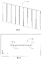
説明されるシステム203は、差し向けられた光210を受け取るための、初期次元に沿って配置された反射素子(図2には集合的に204と符号付けされている)のアレイを含む。説明のために、説明されるシステム203の部分ではないスクリーン208が、図2に、選択された波長がλ1とλNとの間で掃引されるとき、差し向けられた光学ビーム212の空間分布を示すように、描かれる。図2に描かれているように、反射素子204が単一の平面鏡の形態をとる場合、差し向けられた光210の光路210aは、反射光212の光路212bに沿って反射される。同様に、差し向けられた光210の光路210bは、反射光212の光路212aに沿って反射される。単一の平面鏡の場合、像206は連続線の形となる。再び、システム203は、実際には、一般に、任意の時間に、波長チャネルλ1、λ2、...λNのうちの選択された1つを受け取るので、像206は、実際には、説明のために図2に描かれているような連続線ではなく、点を形成する。差し向けられた光学ビーム206の空間的分布は、分散素子202によって生じる初期次元に関連付けられる第1の次元214に沿う。差し向けられた光学ビーム206は、第1の次元214に実質的に直交する第2の次元216に沿って分布しない。
The illustrated
図3~7は、反射素子の種々のアレイを採用することの結果を示す。図3A及び3Bは、比較のために図2の単一の平面鏡の場合を再現する。反射素子204が単一の平面鏡304である場合、選択された波長がλ1とλNとの間で掃引される場合には像206は連続線306の形になる。差し向けられた光学ビーム212の空間的分布は、分散素子202によって生じる初期次元に関連付けられる、第1の次元214に沿う。差し向けられた光学ビーム206は、第2の次元216に沿って分布しない。
Figures 3-7 show the results of employing various arrays of reflective elements. Figures 3A and 3B reproduce the single plane mirror case of Figure 2 for comparison. If the
図4A及び4Bは、反射素子204が、各々、隣接する鏡から小さい間隔で分離された、単一平面鏡404のアレイである場合を表す。像206は、選択された波長がλ1とλNとの間で掃引される場合、破線406の形になる。破線の各々の破れた部分は、波長チャネル(例えば、{λ1、λ2、...λk}、{λk+1、λk+2、...λ2k}、...又は{λN-k+1、λN-k+2、...λN})の帯域を横切る波長掃引を表す。この場合、差し向けられた光学ビーム212の空間的分布は、やはり、分散素子202によって生じる初期次元に関連付けられる第1の次元214に沿う。差し向けられた光学ビーム206は、第2の次元216に沿って分布しない。
4A and 4B represent the case where
図5A及び5Bは、反射素子204が平面鏡504のアレイである場合の、説明されるシステム203の配置を表し、各々の平面鏡は、隣接する鏡から小さい間隔で分離され、平面鏡の各々を通る第1の次元214に沿って延びる直線軸502の周りで互いに傾けられるか、或いは角度オフセットされる。像206は、選択された波長がλ1とλNとの間で掃引される場合、段のある線506の形になる。各々の段は、波長チャネル(例えば、{λ1、λ2、...λk}、{λk+1、λk+2、...λ2k}、...又は{λN-k+1、λN-k+2、...λN})の帯域を横切る波長掃引を表す。角度オフセットの効果は、受け取った光212を、第2の次元216にわたって分布する種々の実質的に平坦な表面(又は本明細書においては「平面」)に向けて反射することであり、この場合、各々の平面は第1の次元214を横切って延びる。差し向けられた光学ビーム206は、第1の次元214及び第2の次元216の両方に沿って分布する。しかし、異なる平面の広がりは第1の次元214内では重ならない。図示されていないが、軸502に直交し、第2の次元216に沿って延びる軸の周りで、平面鏡504が互いにさらに傾けられるか、或いはさらに角度オフセットされる場合には、異なる平面を少なくとも部分的に重なるように構成することができる。この直交する傾きの、像206に対する効果は、段のある線506を第1の次元214に沿って移動させることである。各々の平面鏡504の適切な量の直交する傾きは、段のある線を、互いに十分に重なって2次元ステアリンググリッドを形成するように、移動させることになろう。
Figures 5A and 5B represent the arrangement of the described
図6A及び6Bは、反射素子204が発散鏡504(例えば、反射型シリンダ又は凸表面の形態におけるような)のアレイである場合の、説明されるシステム203の配置を表し、各々の発散鏡は、隣接する鏡から小さい間隔で分離され、発散鏡の各々の中心を通る直線軸602の周りで、互いに傾けられるか又は角度オフセットされる。像206は、選択された波長がλ1とλNとの間で掃引される場合、段のある線606の形になる。各々の段は、波長チャネル(例えば、{λ1、λ2、...λk}、{λk+1、λk+2、...λ2k}、...又は{λN-k+1、λN-k+2、...λN})の帯域を横切る波長掃引を表す。図5A及び5Bに示される場合のように、角度オフセットの効果は、受け取った光212を第2の次元216にわたって分布する種々の平面に向けて反射することであり、この場合、各々の平面は第1の次元214を横切って延びる。発散鏡の使用は、第1の次元214における各々の平面の広がりを拡張するためであり、これは、異なる曲率の発散鏡を使用することによって制御することができる。一般に、発散鏡のより大きい曲率が、第1の次元214に沿って広がる平面のより大きな広がりをもたらす。差し向けられた光学ビーム206は、第1の次元214及び第2の次元216の両方に沿って分布する。
6A and 6B represent the arrangement of the illustrated
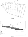
図7A及び7Bは、反射素子204が発散鏡704(例えば、反射型シリンダ又は凸表面の形態におけるような)のアレイである場合の、説明されるシステム203の配置を表し、各々の発散鏡は、隣接する鏡から小さい間隔で分離され、互いに傾けられるか或いは角度オフセットされ、反射素子の各々を通る湾曲軸702の周りに配置される。像206は、選択された波長がλ1とλNとの間で掃引される場合、積層線706の形になる。各々の積層は、波長チャネル(例えば、{λ1、λ2、...λk}、{λk+1、λk+2、...λ2k}、...又は{λN-k+1、λN-k+2、...λN})の帯域を横切る波長掃引を表す。図5A及び5Bに示される場合のように、角度オフセットの効果は、受け取った光212を第2の次元216にわたって分布する種々の平面に向けて反射することであり、この場合、各々の平面は第1の次元214を横切って延びる。角度オフセットは、積層の間隔を調節するように調整することができる。発散鏡の使用は、第1の次元214における各々の平面の広がりを拡張するためであり、これは、異なる曲率の発散鏡を使用することによって制御することができる。一般に、発散鏡のより大きい曲率が、第1の次元214に沿って広がる平面のより大きな広がりをもたらす。一配置において、湾曲軸702は、それぞれの平面を横切る第1の次元214の広がりを均等にするか又は整列させるように、初期次元内の湾曲経路に従う。別の配置において、湾曲軸は放物線状にすることができる。湾曲軸702の曲率は、それぞれの平面を横切る範囲を調節するように調整することができる。差し向けられた光学ビーム206は、第1の次元214及び第2の次元216の両方に沿って分布する。
7A and 7B represent the arrangement of the described
図7Aの配置を用いて、説明されるシステム203は、出射光を、2つの次元214及び216の中の複数の方向(106a、106b、106c...)のうちの1つにおいて、環境110中に空間的に差し向けるように構成することができる。出射光が差し向けられる方向は、複数の波長チャネル(λ1、λ2...λNに中心を有する)の選択された1つに、対応するか、又は基づく。
Using the arrangement of FIG. 7A, the
例
一構成において、複数のスペクトル成分を有するか又は可変波長を有する(例えば、可変波長レーザのCバンド 43nm調整範囲)光源が、波長チャネルの選択を1次元角度分散に変換する回折素子、例えばプリズム又は複合プリズムなどの上に又はそれを通して入射する。この構成において、0.25°/nmの角度分散をもたらすプリズムは、43nmスペクトル範囲を10°の角度分離に変換する。この構成は、角度分散された光を拡大するための拡大望遠鏡(例えば、15X)又は凸面鏡(例えば、半円の)を含む。15Xの拡大望遠鏡を用いると、角度分散は約150°に拡大される。角度拡大器の出力は、凹面鏡の曲率中心に置かれ、出力光が凸面鏡の半径に沿って差し向けられるように配置される。この場合、入射光線は、鏡面に入射することになる際に、伝搬方向が鏡面に垂直であるので、同じであるが反対の方向に沿って反射されることになろう。
Example In one configuration, a light source with multiple spectral components or with tunable wavelengths (e.g., C-band 43 nm tuning range of a tunable wavelength laser) has a diffractive element, e.g., a prism, that converts the selection of wavelength channels into one-dimensional angular dispersion. or incident on or through a compound prism or the like. In this configuration, a prism that provides an angular dispersion of 0.25°/nm transforms the 43 nm spectral range into an angular separation of 10°. This configuration includes a magnifying telescope (eg, 15X) or a convex mirror (eg, semicircular) to magnify the angularly dispersed light. With a 15X magnifying telescope, the angular dispersion is magnified to about 150°. The output of the angle magnifier is placed at the center of curvature of the concave mirror and arranged so that the output light is directed along the radius of the convex mirror. In this case, an incident ray, as it would impinge on a mirrored surface, would be reflected along the same but opposite direction since the direction of propagation is perpendicular to the mirrored surface.
この構成において、凸面鏡の半径が0.05mと仮定すると、入射光によって照射される150°をカバーする弧は0.13m=(0.05×π×150°/180°)となる。一例において、この0.13mの弧は、50個の小部分に分割され、これらの各々は、半径0.0013mの半円凸面鏡を置くように構成される。50個の凸半円の各々への入射光は3°の角度(即ち、150°/50)に対することになるが、小さい半円は、各々の小部分の反射された光が、3°×38.19=114.59°の角度分散を有することになるように角度拡大効果を有することになり、この場合、38.19×の拡大は、半径の比から生じる(即ち、0.05/0.0013=38.19×)。 In this configuration, assuming a convex mirror radius of 0.05 m, the arc covering 150° illuminated by the incident light is 0.13 m = (0.05 x π x 150°/180°). In one example, this 0.13 m arc is divided into 50 sub-sections, each of which is configured to lay a semi-circular convex mirror of radius 0.0013 m. Light incident on each of the 50 convex semi-circles will be for an angle of 3° (i.e., 150°/50), while the smaller semi-circles will cause each minor fraction of reflected light to be 3°× 38.19=114.59°, where the 38.19× expansion results from the ratio of radii (i.e., 0.05/ 0.0013=38.19×).
次に、この構成は図7Aに従って配置することができる。これらの小さい凸半円の各々は、環状部分から構築される。各々の環状部分をZ軸内で前の部分に対して+0.5°傾けることにより、各々の反射光が異なるz軸角度分散(0.5°の増分による)に投射される。この反射光は波長チャネルに基づいて2D像を生成する。この例において、2D像は、0.5°の解像度及び25°(50×0.5°)の垂直視野による、縦の50本の線を含む。水平方向では、この例示的な構成は、光源の波長の最小変化によって制限される解像度で、114.59°をカバーする。 This configuration can then be arranged according to FIG. 7A. Each of these small convex semicircles is constructed from an annular portion. By tilting each annular segment +0.5° relative to the previous segment in the Z-axis, each reflected light is projected to a different z-axis angular dispersion (by 0.5° increments). This reflected light produces a 2D image based on the wavelength channels. In this example, the 2D image contains 50 vertical lines with a resolution of 0.5° and a vertical field of view of 25° (50 x 0.5°). In the horizontal direction, this exemplary configuration covers 114.59° with a resolution limited by the minimum change in wavelength of the light source.
前述に基づいて、光を2次元にわたって差し向けるための光学システムが提供される。その光は、波長帯域にグループ化される複数の波長チャネルのうちの選択された1つを含む。そのシステムは、複数の波長チャネルのうちの選択された1つに基づく初期次元にわたって、光を差し向けるように配置された分散素子と、差し向けられた光を受け取るように、初期次元に沿って配置された反射素子のアレイとを含み、その反射素子は、受け取った光を、それぞれの波長帯域に基づくそれぞれの平面に向けて、反射するように配置され、各々それぞれの平面は、初期次元に関連付けられる第1の次元を横切って延び、それぞれの平面は、第1の次元に実質的に垂直な第2の次元にわたって分布する。 Based on the foregoing, an optical system is provided for directing light across two dimensions. The light includes selected ones of a plurality of wavelength channels grouped into wavelength bands. The system includes a dispersive element arranged to direct light over an initial dimension based on a selected one of a plurality of wavelength channels, and a dispersive element along the initial dimension to receive the directed light. and an array of reflective elements arranged to reflect received light toward respective planes based on respective wavelength bands, each respective plane having an initial dimension. Extending across the associated first dimension, each plane is distributed over a second dimension substantially perpendicular to the first dimension.
光を2次元にわたって差し向ける、対応する方法も提供される。その方法は、光を、分散素子を用いて、複数の波長チャネルのうちの選択された1つに基づく初期次元に沿って配置された反射素子のアレイに、初期次元にわたって差し向けるステップと、この差し向けられた光を、反射素子のアレイを用いて、それぞれの波長帯域に基づくそれぞれの平面に向けて、反射するステップと、を含み、各々それぞれの平面は初期次元に関連付けられる第1の次元を横切って延び、それぞれの平面は、第1の次元に実質的に垂直な第2の次元にわたって分布する。 A corresponding method of directing light across two dimensions is also provided. The method includes the steps of directing light with a dispersive element across an initial dimension to an array of reflective elements arranged along an initial dimension based on a selected one of a plurality of wavelength channels; and reflecting the directed light with the array of reflective elements toward respective planes based on respective wavelength bands, each respective plane having a first dimension associated with the initial dimension. and each plane is distributed over a second dimension substantially perpendicular to the first dimension.
第2の配置
図8を参照すると、説明されるシステム803は、図1におけるビームディレクタ103の役割を果たす。説明されるシステム803は、光源102からの光801を初期次元にわたる第1の方向のうちの1つに向けて(例えば、図8のx軸に沿って)差し向けるように配置された、第1の分散素子を含む。第1の方向の各々は、差し向けられた光810の可能な光路に対応し、次いで、波長チャネルに対応する。例えば、図8に示すように、光路810aは波長チャネルλ1に対応し、光路810bは波長チャネルλNに対応する。第1の方向の幾つかが、図8に、開いた三角形811a及び811bとして表されている。第1の分散素子802は、1つ若しくはそれ以上の回折格子及び/又は1つ若しくはそれ以上のプリズムとすることができる。差し向けられた光810の角度広がりは、波長チャネルの範囲及び分散素子802の分散特性に依存する。説明のための1つの非限定的な例において、光源102は、遠距離通信グレードのレーザを含むことができる。遠距離通信グレードのレーザは、最大40nmまで、例えば、凡そ1527nmから凡そ1567nmまでの、波長調整範囲を有することができる。分散素子802は、均一な線間隔を有する回折格子(透過型回折格子など)を含むことができる。一変形において、回折格子は1000線/mm~1100線/mmの間の格子周期を有することができ、凡そ5~10度の角度広がりを容易にする。別の変形において、回折格子は約600線/mmの格子周期を有することができる。
Second Arrangement Referring to FIG. 8, the
説明されるシステム803は、差し向けられた光810を受け取るための初期次元に沿って配置された第2の分散素子804?1...804-M(集合的に804として言及される)のアレイをさらに含む。この例においては、M個の波長帯域に対応するM個の第2の分散素子が存在する。第2の分散素子のアレイは、受け取った光を第2の方向のうちの1つに向けてさらに差し向けるように構成される。幾つかの、しかし全てではない第2の方向が、図8に、閉じた三角形813a、813b、813c及び813dとして表されている。図8に示すように、第2の方向は、それぞれの波長帯域に基づくそれぞれの実質的に平坦な表面(又は、本明細書では「平面」)に沿って整列される。例えば、分散素子804-1に向けて差し向けられた、波長チャネル{λ1、λ2、...λk}における光は、アレイ804(特に分散素子804-1)により、M個の波長帯域のうちの第1のものに対応する最左端の平面812-1に沿って並べられた方向に向けてさらに差し向けられる。同様に、図示されていないが、分散素子804‐2に向けて差し向けられた、波長チャネル{λk+1、λk+2...λ2k}における光は、アレイ804(特に分散素子804-2)により、M個の波長帯域のうちの第2のものに対応する平面に沿って整列された方向に向けて、さらに差し向けられる、などであり、分散素子804-Mに向けて差し向けられた波長チャネル{λN-k+1、λN-k+2、...λN}における光は、アレイ804(特に分散素子804-M)により、M個の波長帯域のうちのM番目に対応する最右端の平面812-Mに沿って整列された方向に向けて差し向けられる。
The
実際には、システム803は、出力ビームとして差し向けられる光の平面を生じない。むしろ、各々が対応する中心波長に関連付けられる、光の1つ又は少数のビームが、常時、出力ビームとして差し向けられる。図8における平面の図は、説明のためだけに描かれている。即ち、図8に描かれた差し向けられた光810は、光路810a(例えば、波長チャネルλ1に対応する)と光路810b(例えば、波長チャネルλNに対応する)との間の初期次元内の連続的な平面のように見え、他方、図8に描かれた別の差し向けられた光812は、連続的平面812-1、...812-Mのように見えるが、システム803は一般に、常時、波長チャネルλ1、λ2...λNのうちの選択された1つを受け入れる。代替的に、図8における平面の図は、λ1からλNまでの迅速な波長走査を捉えるように見ることができる。
In practice,
さらに、システム803は単一の選択された波長チャネルを用いて説明されているが、当業者であれば、システムは、波長チャネルのうちの少数の選択されたものを同時に又はほぼ同時に受け入れるように適合させることができることを認識するであろう。一例において、光源102は、各々が異なる波長を放射するように調整された複数の波長可変レーザを含む。
Additionally, although the
説明のために、説明されるシステム803の一部ではないスクリーン808が、選択された波長がλ1とλNとの間で掃引されるとき、出力光学ビーム812の空間的分布1000(図10及び以下の説明を参照されたい)を描くために図8に描かれている。第2の分散素子804のアレイは、各々、受け取った光を、個々の第2の分散素子804内に光が入射する位置に応じて、第2の方向のうちの1つに向けて差し向けるように構成される。別々の分散素子804を有するアレイが、説明のために、図8に描かれている。分散素子804は、図示されているように線による間隔で分離されても分離されなくても良い。
For illustration purposes,
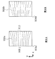
一配置において、第2の分散素子804のアレイは、各々、受け取った光を第2の次元を横切って回折するように、可変線間隔回折格子(例えば、透過型の)を含む。可変線間隔回折格子は、可変線間隔回折格子上の初期次元に沿った(例えば、x軸に沿った)位置群に基づく、複数の格子周期を含む。一配置において、可変線間隔回折格子904aは、第1の端部において、より短い格子周期908を有し、第2の反対側の端部において、より長い格子周期910を有する。格子周期は第1の端部から第2の端部まで増加することができる。一配置において、複数の格子周期における変化は、第2の分散素子のアレイ804を横切って実質的に繰り返す。換言すれば、格子周期は、第2の分散素子の各々の第1の端部から第2の端部まで増加することができる。
In one arrangement, the array of second
図9A及び9Bは、可変線間隔回折格子の2つの配置を示す。図9Aの配置において、格子周期は第1の端部から第2の端部(例えば、間隔1060線/mmを有する)まで連続的に変化する。複数の格子周期の連続的な変化は、滑らかな格子線906aに現れる。この配置の一例において、第1の端部における線間隔908は800線/mmであり、他方、第2の端部における線間隔910は1050線/mmである。波長の変化がない場合にも、線間隔のそのような範囲は凡そ30~35度のビーム発散を引き起こすのに十分である。他の線間隔を使用することもできる。アレイは40mmの長さにすることができる。この例において、各々の可変線間隔回折格子の幅(即ち、第1の端部から第2の端部までの距離)は1mmとすることができ、それによりアレイ804内の約40個の分散素子が可能になる。
Figures 9A and 9B show two arrangements of variable line spacing gratings. In the arrangement of Figure 9A, the grating period varies continuously from the first end to the second end (eg, with a spacing of 1060 lines/mm). A continuous variation of grating periods appears in
回折格子の長さを20mmとすることができ、それにより凡そ少なくとも18,000本の格子線が可能になる。図9Bの配置において、格子周期は第1の端部から第2の端部まで不連続に変化する。複数の格子周期の不連続な変化は、段のある格子線906bに現れる。説明のためだけに、x軸に沿った段はy軸に沿った線で繋がれているが、実際にはy軸に沿った格子線はなくても良いことに留意されたい。
The grating length can be 20 mm, which allows approximately at least 18,000 grating lines. In the arrangement of FIG. 9B, the grating period varies discontinuously from the first end to the second end. A plurality of grating period discontinuities appear in the stepped grating
図9Aに示したような、連続的可変の線間隔回折格子を使用する場合、システム903は、初期次元内に、可変線間隔回折格子で受け取られた光を閉じ込める(例えば、収束させる)収束素子(図示せず)をさらに含むことができる。収束作用は、光学ビームの空間的広がりを、初期次元に沿って十分に小さく保ち、凡そ均一に間隔をあけられた格子を基本的に見る又は照射することを目標とする。一例において、収束素子は初期次元内で(即ち、x軸に沿って)湾曲した円筒型レンズである。光が、可変線間隔回折格子において受け取られるとき、収束素子によって収束され、閉じ込められた後、可変線間隔回折格子から出る光は発散する可能性があり、コリメーションを必要とする。一配置において、システム803は収束された光をコリメートするためのコリメート素子を含む。システム803は、コリメートされた光を整形し、差し向け、フィルタするか又は影響を及ぼすための別の光学素子含むことができるが、コリメートされた光は、最後に、環境110に差し向けられる。
When using a continuously variable line-spacing grating, such as that shown in FIG. 9A, system 903 includes a focusing element that confines (eg, focuses) light received at the variable line-spacing grating within an initial dimension. (not shown). Focusing is aimed at keeping the spatial extent of the optical beam small enough along the initial dimension to essentially view or illuminate a roughly uniformly spaced grating. In one example, the converging element is a cylindrical lens curved in the initial dimension (ie, along the x-axis). When light is received at a variable line spacing grating, after being focused and confined by a focusing element, the light exiting the variable line spacing grating can diverge and require collimation. In one arrangement,
代替的配置において、第2の分散素子は各々、図9A又は9Bの可変線間隔回折格子として機能する、位置依存反射素子を含むことができる。第1の構成において、図9Bの不連続可変線間隔回折格子に類似して、各々の分散素子804-Xは一組の反射素子(例えば、平面鏡又はMEM)を含み、各々の反射素子は、初期次元に沿って位置決めされ、光を第2の方向のそれぞれ1つに反射するように配置される。例えば、この代替的配置をもたらすために、受け取られた光によって局所均一な格子周期を有するように見られる図9Bにおける不連続可変線間隔回折格子の各部分を、第1の分散素子から、平面812-1、812-2...812-Mの中の対応する平面に沿って整列されたそれぞれの方向に、光を反射するように角度を調整された平面鏡で置き換えることができ、ここで、それぞれの方向は、初期次元に沿ったそれぞれの平面鏡の位置に関連付けられる。第2の構成において、図9Aの連続可変線間隔回折格子に類似して、第1の構成の一組の反射素子を、湾曲した反射表面として一体的に形成することができる。換言すれば、この代替的配置の両方の構成は、可変線間隔回折格子のそれぞれの部分として、同じ差し向け効果を達成する。厳密に言えば、この代替的配置における反射素子だけが、波長に基づいて光を差し向けるのではないが、それらは、第1の分散素子による初期分散の集合的効果及び反射の空間依存角度に基づく、第2の分散素子の全体的な分散効果を達成する。換言すれば、反射素子のアレイがそれら自体で分散的ではない場合にも、各々、異なる波長チャネルを受け取り、受け取った光を異なるように反射するように角度を付けられた反射素子は、反射素子が波長対応可能なステアリングをもたらすので、第2の分散素子の機能を達成すると考えられる。 In an alternative arrangement, each of the second dispersive elements can comprise a position dependent reflective element that functions as the variable line spacing grating of Figures 9A or 9B. In a first configuration, similar to the discrete variable line spacing grating of FIG. 9B, each dispersive element 804-X includes a set of reflective elements (eg, plane mirrors or MEMs), each reflective element Positioned along the initial dimension and arranged to reflect light in a respective one of the second directions. For example, to provide this alternative arrangement, each portion of the discontinuous variable line spacing grating in FIG. 812-1, 812-2. . . 812-M can be replaced by plane mirrors angled to reflect light in respective directions aligned along corresponding planes in 812-M, where each direction is along the initial dimension associated with the position of each plane mirror. In a second configuration, a set of reflective elements of the first configuration can be integrally formed as curved reflective surfaces, similar to the continuously variable line spacing grating of FIG. 9A. In other words, both configurations of this alternative arrangement achieve the same pointing effect as respective parts of the variable line spacing grating. Strictly speaking, the reflective elements in this alternative arrangement are not the only ones that direct light based on wavelength, but they are influenced by the collective effect of the initial dispersion by the first dispersive element and the spatially dependent angle of reflection. , to achieve the overall dispersive effect of the second dispersive element. In other words, even if the array of reflective elements are not themselves dispersive, each reflective element receives a different wavelength channel and is angled to reflect the received light differently. is believed to achieve the function of a second dispersive element, as it provides wavelength-aware steering.
図10Aは、そのような代替的配置の第2の構成1000Aを示す。構成1000Aは、各々、湾曲した反射表面1006を含む、第2の分散素子(この図においては、1004-1、1004-2、...1004-11)のアレイ1004を含む。図10Bに概略的に描かれるように、各々の第2の分散素子(例えば、1004-1)の湾曲した反射表面1006は、x-y面内で、x軸に平行な軸1008の周りに平坦な表面1006Aを「ねじる」ことによって形成されると理解することができる。例えば、図10B(a)及び(b)を参照すると、平坦な反射表面1006Aから開始し、素子1004-1の第1の端部1010を、軸1008の周りに、一方向に(例えば、時計回りに)変形可能に回転させ、他方、素子1004-1の第2の反対側の端部1012を、軸1008の周りに、反対の方向に(例えば、反時計回りに)変形可能に回転させる。実際には、湾曲表面1006の形成は変形による必要はなく、例えば、高精度ミリングとそれに続く表面研磨及び被覆(例えば、金を用いた)によることができる。
FIG. 10A shows a
結果として得られる表面輪郭を破線で示す図10B(c)を参照すると、第1の分散素子802によって差し向けられ、第1の端部1010の近くに入射する光(図10B(c)におけるλ1)は、1つのy方向(例えば、正のy方向)に向けて反射され、他方、第1の分散素子802によって差し向けられ、第2の端部1012の近くに入射する光(図10Bにおけるλk)は、異なるy方向(例えば、負のy方向)に向けて反射される。換言すれば、反射表面の法線ベクトルは、x軸に沿った位置に基づいて変化する。法線ベクトルの変化は連続的とするか、又は位置と共に不連続とすることができる。x軸に沿って位置決めされた、各々の付加的な第2の分散素子1004-Xは、第1及び第2の端部と同様に、反対方向に「ねじられる」ように構成され、波長が変化する際にラスタービームのステアリングを容易にする。例えば、光が波長帯域λ1~λk内で波長を変化させる際(即ち、1つの第2の分散素子を横切って入射するとき)光は正のy方向から負のy方向まで掃引され、光が波長を次の波長帯域λk+1~λ2kに変化させる際(即ち、次の第2の分散素子に入射するとき)x軸に沿って段を付けられる、などである。前述のように、一構成において、各々の第2の分散素子1004-Xの湾曲表面1006は、各々が、例えば、正のy方向から負のy方向まで光を反射するように、徐々に増加する角度を付けられた一組の平坦な反射素子によって代替的に形成することができる。
Referring to FIG. 10B(c), which shows the resulting surface profile in dashed lines, light directed by the first
図10Aの配置1000Aには、隣接する分散素子1004-Xの間の境界に急な段が存在する。ここで、急な段は、x-y平面に直行し、隣接する分散素子1004-Xの湾曲表面1006に隣接する隣接表面1014を含む。図10Cに示される代替的な配置1000Cにおいて、急な段は、x方向にジグザグ様式で現れる。ここで、隣接表面1014Cは、入射光を受け取る湾曲表面1006Cの鏡像である。配置1000Cの上端部1018及び下端部1020に沿ったジグザグパターンは、互いの反転バージョンである。図11は、出射光を遮るように、システム803の出力部に置かれたスクリーン808の像1100を概略的に示す。図11の各々の点は、波長チャネルλ1、λ2、...λNのうちの選択された1つを表す。各々の点は、実際には、選択された波長チャネルに基づいて、自然に現れるが、説明のために図11には全ての点が、それらが同時に捕捉できるかのように、描かれていることに留意されたい。像1100は、光出力のM個のグループ(1102-1、1102-2...1102-M)を含む。光出力のM個のグループは、M個の第2の分散素子(804-1...M)、M個の波長帯域及びM個の平面(812-1...M)に対応する。これらの平面は第1の次元にわたって分布し、各々は、第1の次元に実質的に垂直な第2の次元を横切って延びる。第1の次元は、必ずしも正確に初期次元(即ち、図8におけるx軸)と一致する必要はなく、第2の次元は、必ずしも正確に初期次元に直交する次元(即ち、図8におけるy軸)と一致する必要はない。図11に示されるように、光出力の各々のグループは、y軸から小さい角度で傾けられるように表されている。小さい角度の傾きは、第1の分散素子202によって生成される小さい波長依存分散から生じ、第2の次元の中に位置依存分散をもたらすために各々の第2の分散素子の初期次元に沿った種々異なる位置を照射するのに必要である。この傾きは、実際には、些細なものであり、及び/又は、例えば、平面812-1、812-2...812-Mが、物理的な世界フレーム内の真の垂直軸(即ち、経線)に整列するように、取り付け角度を物理的に調節することによって、容易に補正若しくは適合される。
In
図8の配置を用いると、説明されるシステム803は、出射光を、環境110内への2次元814及び816における複数の方向(106a、106b、106c...)のうちの1つの中へ、空間的に差し向けるように構成することができる。出射光が差し向けられる方向は、複数の波長チャネル(λ1、λ2、...λNに中心を有する)のうちの選択された1つに対応するか、又はそれに基づく。
Using the arrangement of FIG. 8, the
一般的配置
上記の開示は、光の波長依存の2次元ステアリングを容易にするための、1つ又はそれ以上の反射、屈折及び回折素子を含む配置を説明する。より一般的には、ステアリングは、複数の波長チャネルのうちの選択された1つに基づく1次元に沿った種々異なる位置に光を差し向け、さらに、種々異なる位置に基づく別の次元に沿った種々異なる方向に、光をステアリングするための1つ又はそれ以上のステアリング素子を用いて、光を差し向けることによって達成され得る。波長依存の方向は、例えば、1つ又はそれ以上のプリズム、1つ又はそれ以上の回折格子及び1つ又はそれ以上のグリズムの任意の組み合わせなどの分散素子を用いて達成することができる。ステアリング素子は、位置依存方向性影響を、例えば、反射、屈折又は回折を介して、光に及ぼす。例えば、図7A及び7Bの配置において、ステアリング素子は、その法線ベクトルが位置と共に変化する、凸型反射表面のアレイである。別の例として、図9A及び9Bの配置において、ステアリング素子は、その格子周期が位置と共に変化する、可変線間隔回折格子のアレイである。さらに別の例として、図10A及び10Bの配置において、ステアリング素子は、その法線ベクトルが位置と共に変化する、湾曲した又は「ねじられた」反射表面のアレイである。
General Arrangements The above disclosure describes arrangements that include one or more reflective, refractive and diffractive elements to facilitate wavelength-dependent two-dimensional steering of light. More generally, the steering directs light to different positions along one dimension based on a selected one of the multiple wavelength channels, and also along another dimension based on different positions. This can be achieved by directing the light in different directions using one or more steering elements to steer the light. Wavelength dependent orientation can be achieved using dispersive elements such as, for example, any combination of one or more prisms, one or more diffraction gratings and one or more grisms. Steering elements exert a position-dependent directional effect on light, for example, via reflection, refraction or diffraction. For example, in the arrangement of Figures 7A and 7B, the steering element is an array of convex reflective surfaces whose normal vectors vary with position. As another example, in the arrangement of Figures 9A and 9B, the steering element is an array of variable line spacing gratings whose grating period varies with position. As yet another example, in the arrangement of Figures 10A and 10B, the steering elements are arrays of curved or "twisted" reflective surfaces whose normal vectors vary with position.
当業者であれば、反射、屈折及び回折素子のいずれも、位置依存方向性影響を及ぼすための他の2つの素子のいずれか又は両方に基づく類似の相当物を有することが多いことを認識するであろう。例えば、凹面(凸面)鏡及び凸(凹)レンズは、収束(収束ぼかし)素子の反射-屈折相当物であり、前者は反射モードで使用され、後者は透過モードで使用される。一例として、図7A及び7Bの配置において、凸型反射表面のアレイは、ステアリング素子としての凹レンズのアレイで置き換えることができる。既に上述した別の例として、図9A及び9Bの配置における可変線間隔回折格子は、ステアリング素子としての図10A及び10Bの湾曲した又は「ねじられた」反射表面のアレイによって置き換えることができる。従って、ステアリング素子は、1つ又はそれ以上の反射、屈折又は回折素子の形態にすることができる。1つのタイプの素子の説明は、鏡の修正物により、別のタイプの素子にも当てはまり得る。 Those skilled in the art will recognize that all reflective, refractive and diffractive elements often have similar equivalents based on either or both of the other two elements for position dependent directional effects. Will. For example, concave (convex) mirrors and convex (concave) lenses are the reflective-refractive equivalents of converging (converging-blurring) elements, the former being used in reflective mode and the latter in transmissive mode. As an example, in the arrangement of Figures 7A and 7B, the array of convex reflective surfaces can be replaced with an array of concave lenses as steering elements. As another example already mentioned above, the variable line spacing gratings in the arrangements of Figures 9A and 9B can be replaced by the array of curved or "twisted" reflective surfaces of Figures 10A and 10B as steering elements. Accordingly, the steering elements may be in the form of one or more reflective, refractive or diffractive elements. A description of one type of element may also apply to another type of element due to mirror modifications.
次に、本開示のその配置を説明するが、当業者には、説明する配置のうちの少なくとも1つは、以下の利点を有することが明白であろう:
・ 波長依存のビームディレクタの使用は、ビームの再差し向けの速度を改善するための慣性無しに又はほとんど無しに、出射光を波長に基づく方向に差し向ける。
・ 一次元における指向性ステアリングに現れる波長可変性は、1つ又はそれ以上の反射、屈折及び回折素子などの多数の類似のステアリング素子を用いで2次元に変換することができる。
The arrangements of the present disclosure will now be described, and it will be apparent to those skilled in the art that at least one of the arrangements described has the following advantages:
• The use of a wavelength dependent beam director directs the output light in a wavelength-based direction with little or no inertia to improve the speed of beam redirection.
• The tunability that appears in directional steering in one dimension can be converted to two dimensions using a number of similar steering elements, such as one or more of reflective, refractive and diffractive elements.
この明細書において開示され定められる本開示は、本文又は図面により言及された又は明白な2つ又はそれ以上の個々の特徴の全ての代替的組み合わせに及ぶことを理解されたい。これらの種々異なる組み合わせの全ては、本開示の種々の代替的態様を構成する。例えば、以下の記述による開示が提供される。 It is to be understood that the disclosure disclosed and defined in this specification extends to all alternative combinations of two or more of the individual features mentioned or apparent from the text or drawings. All of these different combinations constitute various alternative aspects of the present disclosure. For example, disclosure is provided by the following description.
i. 2次元にわたって光を差し向けるための光学システムであって、その光は、波長帯域にグループ化される複数の波長チャネルのうちの選択された1つを含み、そのシステムは、
光を、複数の波長チャネルのうちの選択された1つに基づく初期次元にわたって、差し向けるように配置された分散素子と、
差し向けられた光を受け取るように初期次元に沿って配置されたステアリング素子のアレイと、
を含み、ステアリング素子は受け取った光をそれぞれの波長帯域に基づくそれぞれの平面に向けてさらに差し向けるように配置され、各々それぞれの平面は初期次元に関連付けられる第1の次元を横切って延び、それぞれの平面は、第1の次元に実質的に垂直な第2の次元にわたって分布する、
光学システム。
i. An optical system for directing light across two dimensions, the light including selected ones of a plurality of wavelength channels grouped into wavelength bands, the system comprising:
a dispersive element arranged to direct light over an initial dimension based on a selected one of the plurality of wavelength channels;
an array of steering elements arranged along the initial dimension to receive the directed light;
and the steering elements are arranged to further direct received light toward respective planes based on respective wavelength bands, each respective plane extending across a first dimension associated with the initial dimension, each are distributed over a second dimension substantially perpendicular to the first dimension,
optical system.
ii. ステアリング素子のアレイの各々が反射素子、屈折及び回折素子のいずれか1つを含む、記述iの光学システム。 ii. The optical system of statement i, wherein each of the array of steering elements includes any one of reflective, refractive and diffractive elements.
iii. 反射素子のアレイが、それぞれの平面を横切る第1の次元の範囲を均等化するか又は整列させるため凹型経路に従うように、初期次元に沿って配置される、記述iiの光学システム。 iii. The optical system of statement ii, wherein the array of reflective elements are arranged along the initial dimension to follow a concave path to equalize or align the extent of the first dimension across their respective planes.
iv. 反射素子のアレイが、受け取った光をそれぞれの平面に向けて反射するように、互いに角度オフセットされる、記述iiiの光学システム。 iv. The optical system of statement iii, wherein the arrays of reflective elements are angularly offset from each other so as to reflect received light towards respective planes.
v. 分散素子が、初期次元にわたって光を差し向けるための1つ又はそれ以上の回折格子及び1つ又はそれ以上のプリズムを含む、記述iの光学システム。 v. The optical system of statement i, wherein the dispersive element comprises one or more diffraction gratings and one or more prisms for directing light over an initial dimension.
vi. 2次元にわたって光を差し向ける方法であって、その光は、波長帯域にグループ化される複数の波長チャネルのうちの選択された1つを含み、その方法は、
分散素子を用いて、複数の波長チャネルのうちの選択された1つに基づく初期次元に沿って配置された反射素子のアレイにおいて、初期次元にわたって光を差し向けるステップと、
差し向けられた光を、反射素子のアレイを用いて、それぞれの波長帯域に基づくそれぞれの平面に向けて反射するステップと、
を含み、各々それぞれの平面は初期次元に関連付けられる第1の次元を横切って延び、それぞれの平面は、第1の次元に実質的に垂直な第2の次元にわたって分布する、
方法。
vi. A method of directing light across two dimensions, the light including selected ones of a plurality of wavelength channels grouped into wavelength bands, the method comprising:
using a dispersive element to direct light across an initial dimension at an array of reflective elements arranged along an initial dimension based on a selected one of a plurality of wavelength channels;
reflecting the directed light with an array of reflective elements toward respective planes based on respective wavelength bands;
wherein each respective plane extends across a first dimension associated with the initial dimension and each plane is distributed over a second dimension substantially perpendicular to the first dimension;
Method.
vii. 2次元にわたって光を差し向けるための光学システムであって、その光は、波長帯域にグループ化される複数の波長チャネルのうちの選択された1つを含み、そのシステムは、
複数の波長チャネルのうちの選択された1つに基づく初期次元にわたり、第1の方向のうちの1つに向けて光を差し向けるように配置された第1の分散素子と、
差し向けられた光を受け取るように初期次元に沿って配置された第2の分散素子のアレイと、
を含み、第2の分散素子のアレイは受け取った光を第2の方向のうちに1つに向けてさらに差し向けるように構成され、第2の方向はそれぞれの波長帯域に基づくそれぞれの平面に沿って整列され、その平面は初期次元に関連付けられる第1の次元にわたって分布し、各々の平面は、第1の次元に実質的に垂直な第2の次元を横切って延びる、
光学システム。
vii. An optical system for directing light across two dimensions, the light including selected ones of a plurality of wavelength channels grouped into wavelength bands, the system comprising:
a first dispersive element arranged to direct light in one of the first directions over an initial dimension based on a selected one of the plurality of wavelength channels;
a second array of dispersive elements arranged along the initial dimension to receive the directed light;
and the second array of dispersive elements is configured to further direct received light in one of second directions, the second directions in respective planes based on respective wavelength bands. with the planes distributed across a first dimension associated with the initial dimension and each plane extending across a second dimension substantially perpendicular to the first dimension;
optical system.
viii. 第2の分散素子のアレイは、各々、受け取った光を第2の次元を横切って回折するための可変線間隔回折格子を含む、記述viiの光学システム。 viii. The optical system of description vii, wherein the second array of dispersive elements each includes a variable line spacing grating for diffracting received light across a second dimension.
ix. 可変線間隔回折格子は、可変線間隔回折格子上の初期次元に沿った位置群に基づく複数の格子周期を含む、記述viiiの光学システム。 ix. The optical system of description viii, wherein the variable line-spacing grating includes a plurality of grating periods based on positions along the initial dimension on the variable line-spacing grating.
x. 複数の格子周期は初期次元に沿って連続的に変化する、記述ixの光学システム。 x. The optical system of statement ix, wherein the plurality of grating periods varies continuously along the initial dimension.
xi. 複数の格子周期は初期次元に沿って不連続に変化する、記述xの光学システム。 xi. The optical system of description x, wherein the plurality of grating periods varies discontinuously along the initial dimension.
xii. 複数の格子周期の変化は、第2の分散素子のアレイを横切って実質的に繰り返す、記述ix~xiのいずれか1つの光学システム。 xii. The optical system of any one of statements ix-xi, wherein the plurality of grating period changes substantially repeats across the second array of dispersive elements.
xiii. 第2の方向は、可変線間隔回折格子上の初期次元に沿った位置群に対応する、記述ix~xiiのいずれか1つの光学システム。 xiii. The optical system of any one of descriptions ix-xii, wherein the second direction corresponds to a group of positions along the initial dimension on the variable line spacing grating.
xiv. 可変線間隔回折格子において受け取られた差し向けられた光を初期次元内に閉じ込めるための収束素子をさらに含む、記述ix~xiiiのいずれか1つの光学システム。 xiv. The optical system of any one of statements ix-xiii, further comprising a focusing element for confining within an initial dimension the directed light received at the variable line spacing grating.
xv. 収束素子は円筒型レンズである、記述xivの光学システム。 xv. The optical system of statement xiv, wherein the converging element is a cylindrical lens.
xvi. 収束素子によって収束された光をコリメートするためのコリメート素子をさらに含む、記述xiv又はxvの光学システム。 xvi. The optical system of statement xiv or xv, further comprising a collimating element for collimating light focused by the focusing element.
xvii. 第1の分散素子は、光を初期次元にわたって差し向けるための、1つ又はそれ以上の回折格子及び1つ又はそれ以上のプリズムの任意の組み合わせを含む、記述viiの光学システム。 xvii. The optical system of statement vii, wherein the first dispersive element comprises any combination of one or more diffraction gratings and one or more prisms for directing light over the initial dimension.
xviii. 2次元にわたって光を差し向ける方法であって、その光は、波長帯域にグループ化される複数の波長チャネルのうちの選択された1つを含み、その方法は、
第1の分散素子を用いて、複数の波長チャネルのうちの選択された1つに基づく初期次元に沿って配置された第2の分散素子のアレイにおいて、初期次元にわたる第1の方向のうちの1つに向けて、光を差し向けるステップと、
差し向けられた光を、第2の分散素子のアレイを用いて、第2の方向のうちの1つに向けてさらに差し向けるステップと、
を含み、第2の方向はそれぞれの波長帯域に基づくそれぞれの平面に沿って整列され、平面は、初期次元に関連付けられる第1の次元にわたって分布し、各々の平面は、第1の次元に実質的に垂直な第2の次元を横切って延びる、
方法。
xviii. A method of directing light across two dimensions, the light including selected ones of a plurality of wavelength channels grouped into wavelength bands, the method comprising:
In a second array of dispersive elements arranged along an initial dimension based on a selected one of a plurality of wavelength channels, with a first dispersive element in a first direction across the initial dimension. directing the light towards one;
further directing the directed light in one of the second directions with a second array of dispersive elements;
wherein the second directions are aligned along respective planes based on respective wavelength bands, the planes are distributed across a first dimension associated with the initial dimension, and each plane is substantially in the first dimension extending across a second dimension perpendicular to
Method.
Claims (13)
複数の波長のうちの少なくとも1つを含む光を受け取り、前記複数の波長を空間的に分散させるように配置された少なくとも1つの第1の分散素子と、
前記複数の波長の全てよりは少ない、前記複数の波長のうちの第1の複数を有する第1の波長範囲を含む第1の光信号を、前記第1の分散素子から受け取り、前記複数の波長のうちの前記第1の複数を、機械的移動なしに空間的に差し向けることにより、第1の投射を形成するように配置された第1のステアリング素子と、
前記複数の波長の全てよりは少なく、前記複数の波長のうちの前記第1の複数とは異なる、前記複数の波長のうちの第2の複数を有する第2の波長範囲を含む第2の光信号を、前記第1の分散素子から受け取り、前記複数の波長のうちの第2の複数を、機械的移動なしに空間的に差し向けることにより、第2の投射を形成するように配置された第2のステアリング素子と、
を含み、
前記第1の投射及び前記第2の投射は、結合して2次元にわたって広がり、
前記第1の分散素子は、光源光を前記第1の光信号及び前記第2の光信号に分散させるように配置され、
前記光源光は、前記第1の波長範囲及び前記第2の波長範囲を通して走査するように、調整によって配置されることにより、前記第1及び第2の光信号が、それぞれ、前記第1及び第2の投射の方向にステアリングされる、
光学システム。 An optical system for directing light across two dimensions, comprising:
at least one first dispersive element arranged to receive light comprising at least one of a plurality of wavelengths and to spatially disperse the plurality of wavelengths;
receiving from the first dispersive element a first optical signal comprising a first range of wavelengths having a first plurality of wavelengths less than all of the plurality of wavelengths; a first steering element arranged to spatially orient said first plurality of without mechanical movement to form a first projection;
a second light comprising a second wavelength range having a second plurality of wavelengths of said plurality of wavelengths that is less than all of said plurality of wavelengths and is different than said first plurality of wavelengths of said plurality of wavelengths arranged to receive signals from said first dispersive element and spatially direct a second plurality of said plurality of wavelengths without mechanical movement to form a second projection; a second steering element ;
including
the first projection and the second projection jointly extend over two dimensions ;
the first dispersive element is arranged to disperse source light into the first optical signal and the second optical signal;
The source light is arranged to scan through the first wavelength range and the second wavelength range such that the first and second optical signals are respectively the first and second wavelength ranges. steered in the direction of two projections,
optical system.
第1のステアリング素子において、前記第1のステアリング素子を横切って分布する第1の波長範囲を含む第1の光信号を受け取るステップ、及び、前記第1のステアリング素子により、前記第1の光信号を空間的に差し向けることにより、第1の投射を形成するステップと、
第2のステアリング素子において、前記第2のステアリング素子を横切って分布する第2の波長範囲を含み、前記第2の波長範囲は前記第1の波長範囲とは異なる、第2の光信号を受け取るステップ、及び、前記第2のステアリング素子により、前記第2の光信号を空間的に差し向けることにより、第2の投射を形成するステップと、
光源光を、第1の分散素子を通過させることによって前記第1の光信号及び前記第2の光信号を生成するステップと、
前記第1の波長範囲及び前記第2の波長範囲を通して走査するように前記光源光を調整するステップと
を含み、
前記第1の投射及び前記第2の投射は、結合して2次元にわたって広がり、
前記第1の分散素子は前記光源光を前記第1の光信号及び前記第2の光信号に分散させるように配置され、
前記第1及び第2の光信号が、それぞれ、前記第1及び第2の投射の方向にステアリングされる
方法。 A method of directing light across two dimensions, comprising:
receiving , at a first steering element , a first optical signal comprising a first wavelength range distributed across said first steering element; forming a first projection by spatially directing the optical signal of
a second optical signal in a second steering element comprising a second range of wavelengths distributed across said second steering element , said second range of wavelengths being different than said first range of wavelengths and forming a second projection by spatially directing the second optical signal with the second steering element;
generating the first optical signal and the second optical signal by passing source light through a first dispersive element;
adjusting the source light to scan through the first wavelength range and the second wavelength range;
the first projection and the second projection jointly extend over two dimensions ;
the first dispersive element is arranged to disperse the source light into the first optical signal and the second optical signal;
A method wherein said first and second optical signals are steered in directions of said first and second projections, respectively.
請求項8に記載の方法。 said first steering element and said second steering element each comprise a variable line spacing grating or a reflective surface for diffracting said received light to produce said spatial directing; 9. The method of claim 8, wherein the reflective surface normal vector is a reflective element that varies with the position of the reflective surface to produce the spatial orientation.
請求項1に記載の光学システム。 2. The optical system of claim 1, wherein the at least one first dispersive element is arranged to spatially disperse multiple wavelengths along a linear dimension.
請求項10に記載の光学システム。 11. The optical system of claim 10, wherein said first and second steering elements are reflective elements arranged along said linear dimension , said reflective elements forming said array of reflective elements .
請求項10に記載の光学システム。 4. The first and second steering elements are second dispersive elements arranged along the linear dimension , the second dispersive elements forming an array of the second dispersive elements. 11. The optical system according to 10.
請求項1に記載の光学システム。 2. The first and second steering elements each comprise a variable line spacing grating , the variable line spacing grating comprising different grating periods at different locations along the variable line spacing grating. The optical system according to .
Applications Claiming Priority (5)
| Application Number | Priority Date | Filing Date | Title |
|---|---|---|---|
| AU2016904674 | 2016-11-16 | ||
| AU2016904674A AU2016904674A0 (en) | 2016-11-16 | An optical beam director | |
| AU2017902306 | 2017-06-16 | ||
| AU2017902306A AU2017902306A0 (en) | 2017-06-16 | An optical beam director | |
| PCT/AU2017/051255 WO2018090085A1 (en) | 2016-11-16 | 2017-11-15 | An optical beam director |
Publications (3)
| Publication Number | Publication Date |
|---|---|
| JP2019536098A JP2019536098A (en) | 2019-12-12 |
| JP2019536098A5 JP2019536098A5 (en) | 2021-01-07 |
| JP7125582B2 true JP7125582B2 (en) | 2022-08-25 |
Family
ID=62145017
Family Applications (1)
| Application Number | Title | Priority Date | Filing Date |
|---|---|---|---|
| JP2019525995A Active JP7125582B2 (en) | 2016-11-16 | 2017-11-15 | optical beam director |
Country Status (8)
| Country | Link |
|---|---|
| US (1) | US11422238B2 (en) |
| EP (1) | EP3542209B1 (en) |
| JP (1) | JP7125582B2 (en) |
| KR (1) | KR20190079679A (en) |
| CN (1) | CN110168430B (en) |
| AU (1) | AU2017361118B2 (en) |
| CA (1) | CA3044075A1 (en) |
| WO (1) | WO2018090085A1 (en) |
Families Citing this family (19)
| Publication number | Priority date | Publication date | Assignee | Title |
|---|---|---|---|---|
| CN114706095A (en) | 2015-09-28 | 2022-07-05 | 博莱佳私人有限公司 | Spatial analysis measurement system and method |
| US11422238B2 (en) | 2016-11-16 | 2022-08-23 | Baraja Pty Ltd. | Optical beam director |
| US11162789B2 (en) | 2016-12-16 | 2021-11-02 | Baraja Pty Ltd | Estimation of spatial profile of environment |
| CA3073095A1 (en) | 2017-08-25 | 2019-02-28 | Baraja Pty Ltd | Estimation of spatial profile of environment |
| CA3074245A1 (en) | 2017-09-06 | 2019-03-14 | Baraja Pty Ltd | An optical beam director |
| JP2022503383A (en) * | 2018-06-07 | 2022-01-12 | バラハ ピーティーワイ リミテッド | Optical beam director |
| CN112437896A (en) * | 2018-06-21 | 2021-03-02 | 博莱佳私人有限公司 | Light beam direction finder |
| DE102018129152A1 (en) * | 2018-11-20 | 2020-05-20 | Carl Zeiss Ag | Device for two-dimensionally scanning beam deflection of a light beam |
| DE102019100929A1 (en) | 2019-01-15 | 2020-07-16 | Blickfeld GmbH | Long-range detector for LIDAR |
| WO2020154707A1 (en) * | 2019-01-25 | 2020-07-30 | Silc Technologies, Inc. | Steering of output signals in lidar systems |
| US11480685B2 (en) | 2019-05-05 | 2022-10-25 | Apple Inc. | Compact optical packaging of LiDAR systems using diffractive structures behind angled interfaces |
| WO2021001502A1 (en) | 2019-07-03 | 2021-01-07 | Blickfeld GmbH | Post-scanner telescope optics for lidar system |
| CN114072691A (en) | 2019-07-04 | 2022-02-18 | 博莱佳私人有限公司 | Homodyne reception architecture in spatial estimation systems |
| DE102020104601A1 (en) | 2020-02-21 | 2021-08-26 | Blickfeld GmbH | Operability monitoring for light detection and distance measuring systems |
| DE102020113647A1 (en) | 2020-05-20 | 2021-11-25 | Blickfeld GmbH | Optical System for Light Detection and Ranging, LIDAR |
| CN111856481B (en) * | 2020-07-29 | 2021-07-06 | 杭州视光半导体科技有限公司 | Scanner and coaxial and non-coaxial radar system applying same |
| EP4302127A1 (en) * | 2021-03-02 | 2024-01-10 | Denselight Semiconductors Pte Ltd | Beam scanning system for lidar |
| WO2023141672A1 (en) * | 2022-01-28 | 2023-08-03 | Baraja Pty Ltd | Spatial profiling systems and method |
| JP2024000938A (en) * | 2022-06-21 | 2024-01-09 | ソニーセミコンダクタソリューションズ株式会社 | Light detection device and ranging system |
Citations (6)
| Publication number | Priority date | Publication date | Assignee | Title |
|---|---|---|---|---|
| JP2000347065A (en) | 1999-05-13 | 2000-12-15 | Lucent Technol Inc | Optical device |
| US20050213877A1 (en) | 2002-08-08 | 2005-09-29 | Ming-Chiang Wu | Wavelength-selective 1xN2 switches with two-dimensional input/output fiber arrays |
| JP2009222616A (en) | 2008-03-18 | 2009-10-01 | Toyota Central R&D Labs Inc | Method and apparatus for measuring azimuth |
| US20110199621A1 (en) | 2010-02-16 | 2011-08-18 | Massachusetts Institute Of Technology | Single-transducer, three-dimensional laser imaging system and method |
| US20110222574A1 (en) | 2010-03-09 | 2011-09-15 | Massachusetts Institute Of Technology | Two-dimensional wavelength-beam-combining of lasers using first-order grating stack |
| JP2018529955A (en) | 2015-09-28 | 2018-10-11 | バラジャ ピーティーワイ リミテッドBaraja Pty Ltd | Spatial profiling system and method |
Family Cites Families (67)
| Publication number | Priority date | Publication date | Assignee | Title |
|---|---|---|---|---|
| BE791715A (en) | 1971-12-03 | 1973-05-22 | D Comp Gen | FREQUENCY MODULATION TELEMETER |
| US3953667A (en) | 1974-06-28 | 1976-04-27 | Martin Marietta Corporation | Passive and/or active imaging system |
| US4830486A (en) | 1984-03-16 | 1989-05-16 | Goodwin Frank E | Frequency modulated lasar radar |
| DE4427352C1 (en) | 1994-08-02 | 1996-01-18 | Siemens Ag | High resolution distance measurement using FMCW laser radar |
| US6147760A (en) | 1994-08-30 | 2000-11-14 | Geng; Zheng Jason | High speed three dimensional imaging method |
| JPH08189965A (en) | 1995-01-09 | 1996-07-23 | Honda Motor Co Ltd | Radar apparatus for vehicle |
| US5583683A (en) | 1995-06-15 | 1996-12-10 | Optical Corporation Of America | Optical multiplexing device |
| TR199801972T2 (en) | 1996-04-01 | 1999-01-18 | Lockheed Martin Corporation | Birle�ik halde laser/FLIR (lightning infrared) optical system. |
| US6236666B1 (en) | 1996-05-17 | 2001-05-22 | Uab Research Foundation | Semiconductor laser with a superbroadband or multiline spectral output |
| DE19622777A1 (en) | 1996-06-07 | 1997-12-11 | Bosch Gmbh Robert | Sensor system for automatic relative position control |
| US5877851A (en) | 1997-09-24 | 1999-03-02 | The United States Of America As Represented By The Secretary Of The Army | Scannerless ladar architecture employing focal plane detector arrays and FM-CW ranging theory |
| US6031658A (en) | 1998-09-25 | 2000-02-29 | University Of Central Florida | Digital control polarization based optical scanner |
| US6377720B1 (en) | 1999-02-24 | 2002-04-23 | Micro-Optics, Inc. | Inline optical circulators |
| US6263131B1 (en) | 1999-07-02 | 2001-07-17 | Nortel Networks (Photonics) Pty Ltd. | Reflective non-reciprocal optical device |
| US6339661B1 (en) | 1999-10-20 | 2002-01-15 | Micro-Optics, Inc. | Polarization maintaining fiber optic circulators |
| US6687036B2 (en) | 2000-11-03 | 2004-02-03 | Nuonics, Inc. | Multiplexed optical scanner technology |
| JP2002268013A (en) | 2001-03-09 | 2002-09-18 | Furukawa Electric Co Ltd:The | Optical circulator |
| US7016098B2 (en) | 2001-08-31 | 2006-03-21 | Lucent Technologies Inc. | Optical device with configurable channel allocation |
| US6556282B2 (en) | 2001-09-04 | 2003-04-29 | Rosemount Aerospace, Inc. | Combined LOAS and LIDAR system |
| US6665063B2 (en) | 2001-09-04 | 2003-12-16 | Rosemount Aerospace Inc. | Distributed laser obstacle awareness system |
| US20030223748A1 (en) | 2002-02-20 | 2003-12-04 | Stowe Timothy D. | System and method for seamless spectral control |
| TW586022B (en) | 2002-02-26 | 2004-05-01 | Slight Opto Electronics Co Ltd | Moire lens |
| US20040086214A1 (en) | 2002-07-10 | 2004-05-06 | Finisar Corporation | Optical circulator for bi-directional communication |
| US20040135716A1 (en) | 2002-12-10 | 2004-07-15 | Wootton John R. | Laser rangefinder decoy systems and methods |
| WO2006028512A2 (en) | 2004-04-06 | 2006-03-16 | Bae Systems Information And Electronic Systems Integration Inc. | Polyspectral rangefinder for close-in target ranging and identification of incoming threats |
| US7397980B2 (en) | 2004-06-14 | 2008-07-08 | Optium Australia Pty Limited | Dual-source optical wavelength processor |
| US7804053B2 (en) | 2004-12-03 | 2010-09-28 | Lockheed Martin Corporation | Multi-spectral direction finding sensor having plural detection channels capable of collecting plural sets of optical radiation with different bandwidths |
| US7532311B2 (en) | 2005-04-06 | 2009-05-12 | Lockheed Martin Coherent Technologies, Inc. | Efficient lidar with flexible target interrogation pattern |
| CN101273296B (en) | 2005-09-27 | 2012-08-08 | 视觉机器人技术私人有限公司 | Energy signal processing system |
| IL181030A (en) | 2006-01-29 | 2012-04-30 | Rafael Advanced Defense Sys | Time-space multiplexed ladar |
| US7501616B2 (en) | 2006-05-25 | 2009-03-10 | Microvision, Inc. | Method and apparatus for capturing an image of a moving object |
| US7570347B2 (en) | 2007-06-26 | 2009-08-04 | The United States Of America As Represented By The Secretary Of The Army | Chirped amplitude modulation ladar |
| US8179594B1 (en) * | 2007-06-29 | 2012-05-15 | Lockheed Martin Corporation | Method and apparatus for spectral-beam combining of fanned-in laser beams with chromatic-dispersion compensation using a plurality of diffractive gratings |
| EP2212717B1 (en) | 2007-10-09 | 2015-03-18 | Windar Photonics A/S | Coherent lidar system based on a semiconductor laser and amplifier |
| US7986397B1 (en) | 2008-04-30 | 2011-07-26 | Lockheed Martin Coherent Technologies, Inc. | FMCW 3-D LADAR imaging systems and methods with reduced Doppler sensitivity |
| US9102987B2 (en) | 2008-05-29 | 2015-08-11 | Kao Corporation | Method of detecting paecilomyces variotii |
| IL200332A0 (en) | 2008-08-19 | 2010-04-29 | Rosemount Aerospace Inc | Lidar system using a pseudo-random pulse sequence |
| US8440952B2 (en) | 2008-11-18 | 2013-05-14 | The Regents Of The University Of California | Methods for optical amplified imaging using a two-dimensional spectral brush |
| JP5167178B2 (en) | 2009-03-18 | 2013-03-21 | 株式会社リコー | High gloss variable printing media and recording method |
| JP5712468B2 (en) | 2009-07-14 | 2015-05-07 | 日産自動車株式会社 | Waveform observation apparatus and method |
| EP2483698B1 (en) | 2009-09-28 | 2015-07-08 | Pentalum Technologies Ltd. | Methods, devices and systems for remote wind sensing |
| JP5489658B2 (en) | 2009-11-05 | 2014-05-14 | キヤノン株式会社 | Measuring device |
| WO2011109760A2 (en) * | 2010-03-05 | 2011-09-09 | TeraDiode, Inc. | Wavelength beam combining system and method |
| US8755652B2 (en) * | 2010-07-26 | 2014-06-17 | Oclaro Technology Limited | Multi-channel optical signal monitoring device and method |
| JP5686342B2 (en) | 2011-01-28 | 2015-03-18 | 国立大学法人東北大学 | Laser radar device and laser synthetic aperture radar device |
| US8659748B2 (en) | 2011-02-15 | 2014-02-25 | Optical Air Data Systems, Llc | Scanning non-scanning LIDAR |
| EP2796890B1 (en) | 2011-12-21 | 2017-06-28 | Mitsubishi Electric Corporation | Laser radar device |
| US8908160B2 (en) | 2011-12-23 | 2014-12-09 | Optical Air Data Systems, Llc | Optical air data system suite of sensors |
| WO2013107853A1 (en) | 2012-01-20 | 2013-07-25 | Technische Universiteit Eindhoven | Two-dimensional optical beam steering module |
| WO2013119858A1 (en) * | 2012-02-07 | 2013-08-15 | Dueck Robert | Two-dimensional laser system employing two dispersive elements |
| EP2626722B1 (en) | 2012-02-07 | 2016-09-21 | Sick AG | Optoelectronic sensor and method for recording and determining the distance of an object |
| US9851443B2 (en) | 2012-03-16 | 2017-12-26 | Alcatel Lucent | Optical beam sweeper |
| EP2856207B1 (en) | 2012-05-29 | 2020-11-11 | Brightway Vision Ltd. | Gated imaging using an adaptive depth of field |
| US9103992B1 (en) | 2012-11-01 | 2015-08-11 | Capella Photonics, Inc. | Flexible bandwidth wavelength selective switch |
| US9435957B1 (en) * | 2012-11-07 | 2016-09-06 | Coadna Photonics Inc. | Cyclic demultiplexer with grating and mirror array |
| US9684076B1 (en) | 2013-03-15 | 2017-06-20 | Daniel Feldkhun | Frequency multiplexed ranging |
| DE102013215627A1 (en) | 2013-08-08 | 2015-02-12 | Robert Bosch Gmbh | Light detection device and control method |
| US9490895B2 (en) | 2013-09-20 | 2016-11-08 | Finisar Corporation | Ultrafast high resolution optical channel monitor |
| US9443310B2 (en) * | 2013-10-09 | 2016-09-13 | Microsoft Technology Licensing, Llc | Illumination modules that emit structured light |
| EP3441790A1 (en) | 2013-10-23 | 2019-02-13 | Ladar Limited | A laser detection and ranging device for detecting an object under a water surface |
| WO2015087564A1 (en) | 2013-12-10 | 2015-06-18 | 三菱電機株式会社 | Laser radar device |
| US20150192677A1 (en) | 2014-01-03 | 2015-07-09 | Quanergy Systems, Inc. | Distributed lidar sensing system for wide field of view three dimensional mapping and method of using same |
| KR20150095033A (en) | 2014-02-12 | 2015-08-20 | 한국전자통신연구원 | Laser radar apparatus and method for acquiring image thereof |
| EP3217879B1 (en) * | 2014-11-11 | 2020-01-08 | Koninklijke Philips N.V. | Source-detector arrangement |
| WO2016097409A2 (en) | 2014-12-19 | 2016-06-23 | Windar Photonic A/S | Lidar based on mems |
| KR20180013598A (en) | 2016-07-29 | 2018-02-07 | 삼성전자주식회사 | Beam steering device and optical apparatus including the same |
| US11422238B2 (en) | 2016-11-16 | 2022-08-23 | Baraja Pty Ltd. | Optical beam director |
-
2017
- 2017-11-15 US US16/461,769 patent/US11422238B2/en active Active
- 2017-11-15 JP JP2019525995A patent/JP7125582B2/en active Active
- 2017-11-15 AU AU2017361118A patent/AU2017361118B2/en active Active
- 2017-11-15 CA CA3044075A patent/CA3044075A1/en active Pending
- 2017-11-15 EP EP17871153.7A patent/EP3542209B1/en active Active
- 2017-11-15 KR KR1020197017248A patent/KR20190079679A/en not_active Application Discontinuation
- 2017-11-15 CN CN201780070963.0A patent/CN110168430B/en active Active
- 2017-11-15 WO PCT/AU2017/051255 patent/WO2018090085A1/en active Search and Examination
Patent Citations (6)
| Publication number | Priority date | Publication date | Assignee | Title |
|---|---|---|---|---|
| JP2000347065A (en) | 1999-05-13 | 2000-12-15 | Lucent Technol Inc | Optical device |
| US20050213877A1 (en) | 2002-08-08 | 2005-09-29 | Ming-Chiang Wu | Wavelength-selective 1xN2 switches with two-dimensional input/output fiber arrays |
| JP2009222616A (en) | 2008-03-18 | 2009-10-01 | Toyota Central R&D Labs Inc | Method and apparatus for measuring azimuth |
| US20110199621A1 (en) | 2010-02-16 | 2011-08-18 | Massachusetts Institute Of Technology | Single-transducer, three-dimensional laser imaging system and method |
| US20110222574A1 (en) | 2010-03-09 | 2011-09-15 | Massachusetts Institute Of Technology | Two-dimensional wavelength-beam-combining of lasers using first-order grating stack |
| JP2018529955A (en) | 2015-09-28 | 2018-10-11 | バラジャ ピーティーワイ リミテッドBaraja Pty Ltd | Spatial profiling system and method |
Also Published As
| Publication number | Publication date |
|---|---|
| KR20190079679A (en) | 2019-07-05 |
| CN110168430B (en) | 2022-08-23 |
| JP2019536098A (en) | 2019-12-12 |
| US20190361097A1 (en) | 2019-11-28 |
| EP3542209B1 (en) | 2022-03-23 |
| EP3542209A4 (en) | 2020-07-01 |
| CN110168430A (en) | 2019-08-23 |
| AU2017361118A1 (en) | 2019-06-06 |
| AU2017361118B2 (en) | 2021-11-04 |
| EP3542209A1 (en) | 2019-09-25 |
| US11422238B2 (en) | 2022-08-23 |
| WO2018090085A1 (en) | 2018-05-24 |
| CA3044075A1 (en) | 2018-05-24 |
Similar Documents
| Publication | Publication Date | Title |
|---|---|---|
| JP7125582B2 (en) | optical beam director | |
| US7233716B2 (en) | Optical switch | |
| US6795182B2 (en) | Diffractive fourier optics for optical communications | |
| US8811823B2 (en) | Dynamic optical devices | |
| US7440650B2 (en) | Planar lightwave circuit based wavelength selective switch | |
| CN103293698A (en) | Grating-based tunable filter | |
| JP2013125278A (en) | Optical processing device employing digital micromirror device (dmd) and having reduced wavelength dependent loss | |
| CN112513718B (en) | Method and system for RGB luminaire | |
| CN109212766B (en) | Light splitting device, wavelength selection switch and light splitting method | |
| US8208771B2 (en) | Optical switch | |
| CN112526678B (en) | Spectrum processing device and reconfigurable optical add-drop multiplexer | |
| US6728488B1 (en) | Optical systems employing anamorphic beams and diffraction gratings | |
| US7336907B2 (en) | Optical assembly having cylindrical lenses and related method of modulating optical signals | |
| WO2020069371A1 (en) | Method and system for fiber scanning projector with angled eyepiece | |
| US20150241690A1 (en) | Wavelength selection switch | |
| KR20190039453A (en) | image display devices | |
| US6795601B1 (en) | Achromatic optical switching/routing systems | |
| US11852817B2 (en) | Curved waveguide for slim head up displays | |
| JP7377990B2 (en) | Tunable laser-based light source | |
| US20200209643A1 (en) | Diffractive illumination device with increased diffraction angle | |
| KR20220031686A (en) | Multi-channel opto-mechanical addressing device | |
| EP1887393A1 (en) | Planar lightware circuit based wavelength selective switch | |
| JP2005266093A (en) | Dispersion compensator | |
| JP2013125036A (en) | Wavelength selection switch | |
| JP2013125058A (en) | Wavelength selection switch |
Legal Events
| Date | Code | Title | Description |
|---|---|---|---|
| A529 | Written submission of copy of amendment under article 34 pct |
Free format text: JAPANESE INTERMEDIATE CODE: A529 Effective date: 20190717 |
|
| A521 | Request for written amendment filed |
Free format text: JAPANESE INTERMEDIATE CODE: A523 Effective date: 20201027 |
|
| A521 | Request for written amendment filed |
Free format text: JAPANESE INTERMEDIATE CODE: A523 Effective date: 20201113 |
|
| A621 | Written request for application examination |
Free format text: JAPANESE INTERMEDIATE CODE: A621 Effective date: 20201113 |
|
| A977 | Report on retrieval |
Free format text: JAPANESE INTERMEDIATE CODE: A971007 Effective date: 20210831 |
|
| A131 | Notification of reasons for refusal |
Free format text: JAPANESE INTERMEDIATE CODE: A131 Effective date: 20210907 |
|
| A521 | Request for written amendment filed |
Free format text: JAPANESE INTERMEDIATE CODE: A523 Effective date: 20211207 |
|
| A131 | Notification of reasons for refusal |
Free format text: JAPANESE INTERMEDIATE CODE: A131 Effective date: 20220208 |
|
| A521 | Request for written amendment filed |
Free format text: JAPANESE INTERMEDIATE CODE: A523 Effective date: 20220509 |
|
| TRDD | Decision of grant or rejection written | ||
| A01 | Written decision to grant a patent or to grant a registration (utility model) |
Free format text: JAPANESE INTERMEDIATE CODE: A01 Effective date: 20220705 |
|
| A61 | First payment of annual fees (during grant procedure) |
Free format text: JAPANESE INTERMEDIATE CODE: A61 Effective date: 20220720 |
|
| R150 | Certificate of patent or registration of utility model |
Ref document number: 7125582 Country of ref document: JP Free format text: JAPANESE INTERMEDIATE CODE: R150 |