KR20190008094A - Automatic transmission, and manufacturing method for automatic transmission - Google Patents
Automatic transmission, and manufacturing method for automatic transmission Download PDFInfo
- Publication number
- KR20190008094A KR20190008094A KR1020180075440A KR20180075440A KR20190008094A KR 20190008094 A KR20190008094 A KR 20190008094A KR 1020180075440 A KR1020180075440 A KR 1020180075440A KR 20180075440 A KR20180075440 A KR 20180075440A KR 20190008094 A KR20190008094 A KR 20190008094A
- Authority
- KR
- South Korea
- Prior art keywords
- chamber
- transmission
- transmission controller
- oil pump
- wall
- Prior art date
Links
Images
Classifications
-
- F—MECHANICAL ENGINEERING; LIGHTING; HEATING; WEAPONS; BLASTING
- F16—ENGINEERING ELEMENTS AND UNITS; GENERAL MEASURES FOR PRODUCING AND MAINTAINING EFFECTIVE FUNCTIONING OF MACHINES OR INSTALLATIONS; THERMAL INSULATION IN GENERAL
- F16H—GEARING
- F16H57/00—General details of gearing
- F16H57/04—Features relating to lubrication or cooling or heating
- F16H57/042—Guidance of lubricant
- F16H57/0421—Guidance of lubricant on or within the casing, e.g. shields or baffles for collecting lubricant, tubes, pipes, grooves, channels or the like
-
- F—MECHANICAL ENGINEERING; LIGHTING; HEATING; WEAPONS; BLASTING
- F16—ENGINEERING ELEMENTS AND UNITS; GENERAL MEASURES FOR PRODUCING AND MAINTAINING EFFECTIVE FUNCTIONING OF MACHINES OR INSTALLATIONS; THERMAL INSULATION IN GENERAL
- F16H—GEARING
- F16H37/00—Combinations of mechanical gearings, not provided for in groups F16H1/00 - F16H35/00
- F16H37/02—Combinations of mechanical gearings, not provided for in groups F16H1/00 - F16H35/00 comprising essentially only toothed or friction gearings
-
- F—MECHANICAL ENGINEERING; LIGHTING; HEATING; WEAPONS; BLASTING
- F16—ENGINEERING ELEMENTS AND UNITS; GENERAL MEASURES FOR PRODUCING AND MAINTAINING EFFECTIVE FUNCTIONING OF MACHINES OR INSTALLATIONS; THERMAL INSULATION IN GENERAL
- F16H—GEARING
- F16H57/00—General details of gearing
- F16H57/04—Features relating to lubrication or cooling or heating
- F16H57/0402—Cleaning of lubricants, e.g. filters or magnets
- F16H57/0404—Lubricant filters
-
- F—MECHANICAL ENGINEERING; LIGHTING; HEATING; WEAPONS; BLASTING
- F16—ENGINEERING ELEMENTS AND UNITS; GENERAL MEASURES FOR PRODUCING AND MAINTAINING EFFECTIVE FUNCTIONING OF MACHINES OR INSTALLATIONS; THERMAL INSULATION IN GENERAL
- F16H—GEARING
- F16H57/00—General details of gearing
- F16H57/04—Features relating to lubrication or cooling or heating
- F16H57/0412—Cooling or heating; Control of temperature
- F16H57/0413—Controlled cooling or heating of lubricant; Temperature control therefor
-
- F—MECHANICAL ENGINEERING; LIGHTING; HEATING; WEAPONS; BLASTING
- F16—ENGINEERING ELEMENTS AND UNITS; GENERAL MEASURES FOR PRODUCING AND MAINTAINING EFFECTIVE FUNCTIONING OF MACHINES OR INSTALLATIONS; THERMAL INSULATION IN GENERAL
- F16H—GEARING
- F16H57/00—General details of gearing
- F16H57/04—Features relating to lubrication or cooling or heating
- F16H57/0434—Features relating to lubrication or cooling or heating relating to lubrication supply, e.g. pumps ; Pressure control
- F16H57/0436—Pumps
-
- F—MECHANICAL ENGINEERING; LIGHTING; HEATING; WEAPONS; BLASTING
- F16—ENGINEERING ELEMENTS AND UNITS; GENERAL MEASURES FOR PRODUCING AND MAINTAINING EFFECTIVE FUNCTIONING OF MACHINES OR INSTALLATIONS; THERMAL INSULATION IN GENERAL
- F16H—GEARING
- F16H57/00—General details of gearing
- F16H57/04—Features relating to lubrication or cooling or heating
- F16H57/048—Type of gearings to be lubricated, cooled or heated
- F16H57/0487—Friction gearings
- F16H57/0489—Friction gearings with endless flexible members, e.g. belt CVTs
-
- F—MECHANICAL ENGINEERING; LIGHTING; HEATING; WEAPONS; BLASTING
- F16—ENGINEERING ELEMENTS AND UNITS; GENERAL MEASURES FOR PRODUCING AND MAINTAINING EFFECTIVE FUNCTIONING OF MACHINES OR INSTALLATIONS; THERMAL INSULATION IN GENERAL
- F16H—GEARING
- F16H57/00—General details of gearing
- F16H57/02—Gearboxes; Mounting gearing therein
- F16H2057/02039—Gearboxes for particular applications
- F16H2057/02043—Gearboxes for particular applications for vehicle transmissions
- F16H2057/02047—Automatic transmissions
Landscapes
- Engineering & Computer Science (AREA)
- General Engineering & Computer Science (AREA)
- Mechanical Engineering (AREA)
- General Details Of Gearings (AREA)
- Control Of Transmission Device (AREA)
Abstract
Description
본 발명은 자동 변속기 및 자동 변속기의 제조 방법에 관한 것이다.The present invention relates to an automatic transmission and a method of manufacturing the automatic transmission.
차량용의 자동 변속기에는, 당해 자동 변속기의 변속기 컨트롤러(ATCU)를 변속기 케이스의 외측(차량측)에 배치한 것과, 변속기 케이스의 내측에 배치한 것이 있다.The automatic transmission for a vehicle has a transmission controller (ATCU) of the automatic transmission disposed outside the transmission case (on the vehicle side) and inside the transmission case.
예를 들어, 특허문헌 1에는, 변속기 컨트롤러를 변속기 케이스의 내측에 배치하는 것이 개시되어 있다.For example,
특허문헌 1에서는, 변속기 전체를 콤팩트하게 하기 위해서, 변속기 컨트롤러를 변속기 케이스의 내측에 배치하고 있는데, 변속기 컨트롤러를 변속기 케이스의 내측에 배치함에 있어서, 변속기 컨트롤러의 조립을 용이하게 행할 수 있는 것이 바람직하다.
본 발명은The present invention
변속 기구가 배치된 제1 실과,A first chamber in which a transmission mechanism is disposed,
변속기 컨트롤러가 배치되는 제2 실과,A second chamber in which a transmission controller is disposed,
상기 제2 실의 적어도 일부를 구성하는 덮개부를 갖고,And a lid portion constituting at least a part of the second chamber,
상기 변속기 컨트롤러는 상기 덮개부에 탑재되어 있는 구성의 자동 변속기로 하였다.And the transmission controller is mounted on the lid unit.
본 발명에 따르면, 변속기 컨트롤러가 덮개부에 탑재되어 있으므로, 덮개부의 설치를 완료하면, 변속기 컨트롤러의 설치도 동시에 완료되게 된다.According to the present invention, since the transmission controller is mounted on the lid portion, when the installation of the lid portion is completed, the installation of the transmission controller is completed at the same time.
따라서, 변속기 컨트롤러의 조립을 용이하게 행할 수 있다.Therefore, the transmission controller can be easily assembled.
도 1은 실시 형태에 따른 무단 변속기의 각 구성 요소의 변속기 케이스 내에서의 배치를 모식적으로 도시한 도면이다.
도 2는 실시 형태에 따른 무단 변속기에 있어서의 전동 오일 펌프와 변속기 컨트롤러와 오일 쿨러의 배치를 설명하는 도면이다.
도 3은 전동 오일 펌프와 변속기 컨트롤러의 변속기 케이스에 있어서의 배치의 변형예를 설명하는 도면이다.
도 4는 전동 오일 펌프와 변속기 컨트롤러의 변속기 케이스에 있어서의 배치의 변형예를 설명하는 도면이다.
도 5는 전동 오일 펌프와 변속기 컨트롤러의 변속기 케이스에 있어서의 배치의 변형예를 설명하는 도면이다.
도 6은 변속기 컨트롤러와 오일 쿨러의 변속기 케이스에 있어서의 배치의 변형예를 설명하는 도면이다.
도 7은 종래예에 따른 무단 변속기에 있어서의 전동 오일 펌프와 변속기 컨트롤러의 배치를 설명하는 도면이다.Fig. 1 is a diagram schematically showing an arrangement of each constituent element of the continuously variable transmission according to the embodiment in the transmission case. Fig.
2 is a view for explaining the arrangement of the electric oil pump, the transmission controller and the oil cooler in the continuously variable transmission according to the embodiment.
3 is a view for explaining a modification of the arrangement of the transmission oil pump and the transmission controller in the transmission case.
4 is a view for explaining a modification of the arrangement of the transmission oil pump and the transmission controller in the transmission case.
5 is a view for explaining a modification of the arrangement of the transmission oil pump and the transmission controller in the transmission case.
6 is a view for explaining a modification of the arrangement of the transmission controller and the oil cooler in the transmission case.
7 is a view for explaining the arrangement of the electric oil pump and the transmission controller in the conventional continuously variable transmission.
이하, 본 발명의 실시 형태를, 벨트식의 무단 변속기(이하, 자동 변속기라고 표기한다)에 적용한 경우를 예로 들어 설명한다.Hereinafter, an embodiment of the present invention will be described as an example in which the present invention is applied to a belt-type continuously variable transmission (hereinafter referred to as an automatic transmission).
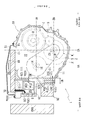
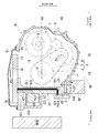
도 1은, 자동 변속기(1)의 각 구성 요소의 변속기 케이스(10) 내에서의 배치를 모식적으로 도시한 도면이다. 또한, 도 1에서는, 변속기 케이스(10) 내에 배치된 배리에이터(2)와, 기어 열(6)과, 파이널 기어(7)와, 차동 장치(8)를 간략적으로 가상선으로 나타내고 있다.1 is a diagram schematically showing the arrangement of each component of the
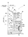
도 2는, 변속기 케이스(10)에 있어서의 전동 오일 펌프(21)와 변속기 컨트롤러(9)(ATCU)의 배치를 설명하는 도면이다. 도 2의 (a)는 도 1의 변속기 케이스(10)의 전동 오일 펌프(21) 주위의 확대도이다. 도 2의 (b)는 변속기 케이스(10)를 도 2의 (a)에 있어서의 A-A 화살표 방향으로부터 본 사시도이며, 덮개부(126) 주위를 확대하여 도시하는 도면이다.Fig. 2 is a view for explaining the arrangement of the
도 1에 도시한 바와 같이, 차량용의 벨트식의 자동 변속기(1)(CVT)의 배리에이터(2)는 프라이머리 풀리(3)와, 세컨더리 풀리(4)와, 동력 전달 부재(5)(벨트)를 갖고 있다.1, a
동력 전달 부재(5)는 양측에 슬릿을 갖는 판상의 엘리먼트를 적층하여 환상으로 배치하고, 엘리먼트의 각각을, 슬릿을 삽입 관통시킨 환상 링으로 결속하여 구성된 벨트이다.The
프라이머리 풀리(3)는 도시하지 않은 구동원의 회전 구동력이 입력되어서 회전축 X1(프라이머리 풀리의 축 중심) 둘레로 회전한다.The
세컨더리 풀리(4)는 회전축 X1에 평행한 회전축 X2(세컨더리 풀리의 축 중심) 둘레에 회전 가능하게 설치되어 있다.The
동력 전달 부재(5)는 프라이머리 풀리(3)의 외주와 세컨더리 풀리(4)의 외주에 감겨 있다. 프라이머리 풀리(3)에 입력된 회전 구동력은, 동력 전달 부재(5)를 통하여 세컨더리 풀리(4)에 전달된다.The
배리에이터(2)에서는, 프라이머리 풀리(3)로부터 세컨더리 풀리(4)에 회전 구동력을 전달할 때에 프라이머리 풀리(3)에 있어서의 동력 전달 부재(5)의 감김 반경과, 세컨더리 풀리(4)에 있어서의 동력 전달 부재(5)의 감김 반경이 변경된다.In the
이에 의해, 프라이머리 풀리(3)에 입력된 회전 구동력이, 원하는 변속비로 변속되어서, 세컨더리 풀리(4)에 전달된다.As a result, the rotational drive force input to the
여기서, 변속비는, 프라이머리 풀리(3)와 세컨더리 풀리(4)에 있어서의 동력 전달 부재(5)의 감김 반경에 따라서 결정된다. 감김 반경은, 자동 변속기(1)를 탑재한 차량의 주행 상태 등에 기초하여, 자동 변속기(1)의 변속기 컨트롤러(9)(ATCU)가 결정한다.Here, the speed ratio is determined according to the winding radius of the
세컨더리 풀리(4)에 전달된 회전 구동력은, 기어 열(6)과, 파이널 기어(7)와, 차동 장치(8)를 통하여, 최종적으로 구동륜(도시하지 않음)에 전달된다.The rotational driving force transmitted to the
본 실시 형태에서는, 배리에이터(2)와, 기어 열(6)과, 파이널 기어(7)로, 변속 기구부를 구성하고 있다.In the present embodiment, the transmission mechanism is constituted by the
프라이머리 풀리(3)의 회전축 X1을 통과하는 수평선 H1은, 세컨더리 풀리(4)의 회전축 X2를 통과하는 수평선 H2보다도, 연직선 방향에 있어서의 하측에 위치하고 있다. 프라이머리 풀리(3)의 회전축 X1과, 세컨더리 풀리(4)의 회전축 X2는, 연직선 방향으로 이격되어 있다.The horizontal line H1 passing through the rotation axis X1 of the
변속기 케이스(10)의 내부에서는, 프라이머리 풀리(3)가 세컨더리 풀리(4)보다도 연직선 방향에 있어서의 하측에 배치되어 있다.Inside the
여기서, 본 명세서에 있어서의 용어 「연직선」은, 중력 방향과 평행한 선을 의미하고, 용어 「수평선」은, 중력 방향과 수직한 선을 의미한다.In this specification, the term " vertical line " means a line parallel to the gravity direction, and the term " horizontal line " means a line perpendicular to the gravity direction.
기어 열(6) 및 파이널 기어(7)와, 세컨더리 풀리(4)는 세컨더리 풀리(4)의 회전축 X2 방향으로 이격되어서 배치되어 있다. 도 1의 경우에는, 기어 열(6)과 파이널 기어(7)는 세컨더리 풀리(4)보다도 지면 전방측에 위치하고 있다.The
도 1의 경우, 변속기 케이스(10)의 내부에서는, 프라이머리 풀리(3)와 세컨더리 풀리(4)가 지면 안측에 위치하고 있다. 기어 열(6)과 파이널 기어(7)가 지면 전방측에 위치하고 있다. 도 1에 도시하는 변속기 케이스(10)는 지면 전방측과 안측에 깊이를 갖고 있고, 변속기 케이스(10)보다도 지면 전방측에, 도시하지 않은 구동원이 위치하고 있다.1, in the interior of the
변속기 케이스(10)의 하부에는 오일 팬(15)이 설치되어 있다. 오일 팬(15)은 변속기 케이스(10)의 하부측의 개구(16)를 막고, 변속기 케이스(10)의 하부에 오일(OL)의 저류 공간이 되는 제3 실(S3)을 형성한다.An
제3 실(S3) 내에는, 컨트롤 밸브 유닛(17)이 위치하고 있다. 컨트롤 밸브 유닛(17)도 또한, 변속기 케이스(10)의 하부에 고정되어 있고, 컨트롤 밸브 유닛(17)에 부설된 오일 스트레이너(18)는 오일 팬(15) 내에 저류시킨 오일(OL) 내에 위치하고 있다.In the third chamber (S3), the control valve unit (17) is located. The
변속기 케이스(10)의 주위벽(11)은 변속기 케이스(10)의 내부에, 변속 기구부의 수용 공간이 되는 제1 실(S1)을 형성한다.The
이 제1 실(S1)에는, 배리에이터(2)의 수용 공간이나, 기어 열(6)과 파이널 기어(7)의 수용 공간이 포함된다.The first chamber S1 includes a space for accommodating the
변속기 케이스(10) 내의 공간은, 주위벽(11)의 하부에 설치한 구획벽(111)에 의해, 오일 팬(15)측의 제3 실(S3)과, 변속 기구부(배리에이터(2))측의 제1 실(S1)로 구획되어 있다.The space in the
주위벽(11)은 프라이머리 풀리(3)의 근방을 연직선 방향으로 연장되는 구획벽부(12)를 갖고 있다. 이 구획벽부(12)는 자동 변속기(1)를 차량에 탑재한 상태에서, 차량 전방측(라디에이터(RAD))측에 위치하고 있다.The peripheral wall (11) has a partition wall portion (12) extending in the vertical direction near the primary pulley (3). The
구획벽부(12)의 외주에는, 오일 쿨러(20)와 전동 오일 펌프(21)가 부설되어 있다. 구획벽부(12)에 있어서 전동 오일 펌프(21)는 오일 쿨러(20)보다도 오일 팬측(연직선 방향에 있어서의 하측)에 설치되어 있다.An
프라이머리 풀리(3)의 회전축 X1 방향으로부터 보아서, 프라이머리 풀리(3)의 회전축 X1을 통과하는 연직선 V1은, 세컨더리 풀리(4)의 회전축 X2를 통과하는 연직선 V2와, 오일 쿨러(20) 사이에 위치하고 있다.The vertical line V1 passing through the rotation axis X1 of the
프라이머리 풀리(3)의 회전축 X1 방향으로부터 보아서, 프라이머리 풀리(3)의 회전축 X1을 통과하는 연직선 V1의 위치는, 세컨더리 풀리(4)의 회전축 X2를 통과하는 연직선 V2와, 전동 오일 펌프(21) 사이이기도 하다.The position of the vertical line V1 passing through the rotation axis X1 of the
구획벽부(12)는 오일 쿨러(20)가 부설된 제1 벽(121)과, 전동 오일 펌프(21)가 부설된 제2 벽(122)을 갖고 있다. 제2 벽(122)은 연직선 방향에 있어서의 제1 벽(121)의 하측에 위치하고 있다.The
수평선 H1 방향에 있어서의 제1 벽(121)의 두께 W1은, 수평선 H1 방향에 있어서의 제2 벽(122)의 두께 W2보다도 두껍게 되어 있다. 제2 벽(122)의 전동 오일 펌프(21)측의 표면(122a)은 제1 벽(121)의 오일 쿨러(20)측의 표면(121a)보다도, 프라이머리 풀리축(31)에 가까운 위치에 배치되어 있다.The thickness W1 of the
그 때문에, 수평선 H1 방향에 있어서의 전동 오일 펌프(21)의 프라이머리 풀리(3)측(도면 중 좌측)의 단부(21a)는 수평선 H1 방향에 있어서의 오일 쿨러(20)의 프라이머리 풀리(3)측(도면 중 좌측)의 단부(20a)보다도, 프라이머리 풀리(3)측에 위치하고 있다.The
전동 오일 펌프(21)의 단부(21a)와, 오일 쿨러(20)의 단부(20a)는 수평선 H1 방향으로 이격되어 있다. 또한, 전동 오일 펌프(21)의 무게 중심 쪽이, 오일 쿨러(20)의 무게 중심보다도, 회전축 X1의 근방에 위치하고 있다.The
제1 벽(121)에는, 오일 필터(201)의 수용부(121b)가 설치되어 있다. 수용부(121b)는 연직선 방향을 따르는 방향에서 설치되어 있다. 오일 필터(201)는 연직선 방향에 있어서의 상측으로부터, 수용부(121b)에 대하여 탈착된다.A receiving
본 실시 형태에서는 오일 쿨러(20)로 식혀진 오일(OL)이, 오일 필터(201)를 통과하고, 제1 실(S1)측으로 되돌려진다.In the present embodiment, the oil OL cooled by the oil cooler 20 passes through the
상기한 바와 같이, 변속기 케이스(10)의 구획벽(111)은 변속기 케이스(10) 내의 공간을, 오일 팬(15)측의 제3 실(S3)과 변속 기구부(배리에이터(2))측의 제1 실(S1)로 구획한다.As described above, the
회전축 X1 방향으로부터 보아서 구획벽(111)은 구획벽부(12)의 제1 벽(121)의 표면(121a)(외주면)보다도 외측(라디에이터(RAD)측)까지 미치는 범위에 설치되어 있다.The
구획벽(111)에서는, 제1 벽(121)의 표면(121a)(외주면)보다도 외측(라디에이터(RAD)측)에 위치하는 영역이, 팽출 영역(111a)으로 되어 있다.In the
연직선 방향에 있어서의 팽출 영역(111a)의 상측에는, 벽부(123)가 설치되어 있다.On the upper side of the
벽부(123)는 제1 벽(121)과 제2 벽(122)의 경계부에서, 변속기 케이스(10)의 외측(라디에이터(RAD)측)을 향하여 연장 돌출되어 있다. 벽부(123)는 수평선 H1에 대하여 대략 평행으로 설치되어 있다.The
변속기 케이스(10)에서는, 연직선 V1 방향에 있어서의 벽부(123)와 팽출 영역(111a) 사이에, 전동 오일 펌프(21)를 수용하는 제2 실(S2)(전동 오일 펌프실)이 형성되어 있다.In the
제2 실(S2) 내에서는, 전동 오일 펌프(21)가 제2 벽(122)의 표면(122a)(외주)에 고정되어 있다. 이 상태에 있어서 전동 오일 펌프(21)는 구획벽(111)의 팽출 영역(111a)과 벽부(123)로, 주위가 둘러싸여 있다.The
제2 실(S2)은, 변속기 케이스(10)의 외측(회전축 X1의 직경 방향 외측)에 개구되어 있고, 이 제2 실(S2)의 개구는, 라디에이터(RAD)에 대향하고 있다.The second chamber S2 is opened outside the transmission case 10 (radially outward of the rotation axis X1), and the opening of the second chamber S2 is opposed to the radiator RAD.
제2 실(S2)의 개구는, 수평선 H1 방향으로 개구되어 있고, 제2 실(S2)의 개구는, 벽부(123)와 팽출 영역(111a)에 걸쳐서 고정된 덮개부(126)로 밀봉되어 있다.The opening of the second chamber S2 is opened in the direction of the horizontal line H1 and the opening of the second chamber S2 is sealed by the
덮개부(126)에 있어서의 제2 실(S2)과의 대향면에는, 오목부(126a)가 형성되어 있다. 이 오목부(126a)에, 자동 변속기(1)의 변속기 컨트롤러(9)(ATCU)가 설치되어 있다. 제2 실(S2)의 개구를 덮개부(126)로 밀봉하면, 덮개부(126)에 설치한 변속기 컨트롤러(9)(ATCU)도 또한, 전동 오일 펌프(21)와 함께 제2 실(S2) 내에 수용된다.A
도 2의 (b)에 도시하는 바와 같이, 덮개부(126)에는, 변속기 컨트롤러(9)에 전기적으로 접속된 커넥터(127)가 일체로 설치되어 있다.As shown in FIG. 2 (b), a connector 127 electrically connected to the
커넥터(127)는 덮개부(126)의 표면(외측면)에 노출되어 있고, 도 1에서는, 덮개부(126)의 지면 안측에 위치하고 있다.The connector 127 is exposed on the surface (outer surface) of the
변속기 컨트롤러(9)는 커넥터(127)에 접속된 외부 배선을 통하여, 차량에 탑재된 다른 제어 장치(예를 들어, 엔진 컨트롤 유닛)에 접속되어 있다.The
제2 실(S2)에는, 구획벽(111)의 팽출 영역(111a)에 설치한 연통 구멍(112)이 개구되어 있다. 연통 구멍(112)은 팽출 영역(111a)을 연직선 방향으로 관통하고 있고, 연통 구멍(112)은 제2 실(S2)과, 오일 팬(15) 내의 제3 실(S3)을, 최단 거리로 연통시키고 있다.In the second chamber S2, the
변속기 컨트롤러(9)(ATCU)로부터 연장하는 와이어하니스(128)는 연통 구멍(112)을 통과하여, 오일 팬(15)측으로 인출된 뒤, 컨트롤 밸브 유닛(17)에 접속되어 있다.The
변속기 컨트롤러(9)(ATCU)는 변속기 컨트롤러(9)(ATCU)가 차량측에 설치되어 있는 종래예(도 7 참조)의 경우보다도 짧은 길이의 와이어하니스(128)로 컨트롤 밸브 유닛(17)에 접속되어 있다.The transmission controller 9 (ATCU) is connected to the
컨트롤 밸브 유닛(17) 내에는, 오일(OL)이 통류하는 유로, 오일(OL)의 압력(유압)을 압력 조절하는 압력 조절 밸브, 오일(OL)의 공급처를 전환하는 전환 밸브 등이 설치되어 있다.A
변속기 컨트롤러(9)는 압력 조절 밸브나 전환 밸브를 구동하는 솔레노이드 등에, 와이어하니스(128)를 통하여, 구동 신호(명령)를 출력한다. 또한, 변속기 케이스(10) 내에 설치한 센서 등의 출력 신호가, 와이어하니스(128)를 통하여, 변속기 컨트롤러(9)에 입력된다.The
전동 오일 펌프(21)가 고정된 제2 벽(122)의 내부에는, 전동 오일 펌프(21)와 컨트롤 밸브 유닛(17)을 접속하는 유로(129)가 설치되어 있다.A
유로(129)는 연직선 방향으로 직선상으로 연장되어 있고, 컨트롤 밸브 유닛(17)과 전동 오일 펌프(21)를 최단 거리로 연락시키고 있다.The
전동 오일 펌프(21)가 구동되면, 오일 팬(15) 내의 오일(OL)이, 오일 스트레이너(18)에 흡인된다. 오일 스트레이너(18)에 흡인된 오일(OL)은, 컨트롤 밸브 유닛(17) 내의 유로(도시하지 않음)와 제2 벽(122) 내의 유로(도시하지 않음)를 통하여, 전동 오일 펌프(21)에 공급된다.When the
전동 오일 펌프(21)는 흡인한 오일(OL)을 가압한 뒤에, 제2 벽(122) 내의 유로(129)를 통하여, 컨트롤 밸브 유닛(17)에 공급한다.The
또한, 이 유로(129)는 제2 벽(122)의 내부를 연직선 방향으로 연장되어 있고, 컨트롤 밸브 유닛(17)과 전동 오일 펌프(21)를 최단 거리로 연락시키고 있다.The
컨트롤 밸브 유닛(17)은 변속기 컨트롤러(9)(ATCU)로부터의 명령에 기초하여, 전환 밸브나 압력 조절 밸브를 구동하고, 자동 변속기(1)(배리에이터(2))의 구동이나 윤활한 필요한 유압을 압력 조절한다.The
그리고, 압력 조절된 유압(오일)에 의해, 자동 변속기(1)가 구비하는 유압 구동 장치(예를 들어, 배리에이터(2)나, 도시하지 않은 마찰 체결장치)가 구동됨과 함께, 윤활이 필요한 부위가 윤활된다.The hydraulic drive device (for example, the
이하, 이러한 구성을 갖는 자동 변속기(1)에 있어서의, 전동 오일 펌프(21)와, 변속기 컨트롤러(9)의 조립 수순을 설명한다.The assembling procedure of the
변속기 케이스(10)에서는, 주위벽(11)의 외측면(회전축 X1의 직경 방향 외측의 표면)에서, 제2 실(S2)이 개구되어 있다.In the
처음에, 전동 오일 펌프(21)를 제2 실(S2)의 개구로부터, 제2 실(S2) 내에 삽입한 뒤, 전동 오일 펌프(21)를 제2 실(S2)의 안쪽에서 노출되는 제2 벽(122)의 표면(122a)에, 볼트(도시하지 않음)로 고정한다.The
오목부(126a)에 변속기 컨트롤러(9)(ATCU)가 설치된 상태의 덮개부(126)를 준비해 두고, 변속기 컨트롤러(9)로부터 인출된 와이어하니스(128)의 선단측을 연통 구멍(112)에 삽입한다.The front end side of the
연통 구멍(112)에 삽입한 와이어하니스(128)를 제3 실(S3)측으로 인출한 뒤, 컨트롤 밸브 유닛(17)에 설치한 커넥터(도시하지 않음)에 접속한다.The
와이어하니스(128)가 접속된 컨트롤 밸브 유닛(17)을 변속기 케이스(10)의 하부에 볼트로 고정한다.The
제2 실(S2)의 개구를, 덮개부(126)에 있어서의 변속기 컨트롤러(9)측의 면으로 막고, 덮개부(126)의 주연부를, 변속기 케이스(10)의 팽출 영역(111a)과 벽부(123)에 볼트(도시하지 않음)로 고정한다. 이때에, 와이어하니스(128)는 제2 실(S2) 내의 간극에 수용한다.The opening of the second chamber S2 is closed by the surface of the
여기서, 제2 실(S2)은, 제1 실(S1) 및 제3 실(S3)로부터 독립하여 형성된 공간이다. 제2 실(S2)은, 변속기 케이스(10)의 제2 벽(122)으로, 제1 실(S1)로부터 구획되어 있어, 구획벽(111)의 팽출 영역(111a)으로, 제3 실(S3)로부터 구획되어 있다.Here, the second chamber S2 is a space formed independently from the first chamber S1 and the third chamber S3. The second chamber S2 is partitioned from the first chamber S1 by the
따라서, 제2 실(S2)은, 변속 기구부(회전체)를 수용하는 제1 실(S1)이나, 오일을 저류하는 제3 실(S3)로부터 구획되어 있다.Therefore, the second chamber S2 is partitioned from the first chamber S1 that houses the transmission mechanism (rotation body) and the third chamber S3 that stores the oil.
팽출 영역(111a)에는, 제2 실(S2)과 제3 실(S3)을 연통시키는 연통 구멍(112)이 설치되어 있는데, 이 연통 구멍(112)은 이 연통 구멍(112) 내에 설치된 와이어하니스(128)로, 개구 범위가 좁혀져 있다.A communicating
또한, 제3 실(S3)에는, 제1 실(S1)과는 달리, 오일을 쓸어올리는 회전체가 설치되어 있지 않다. 그리고, 제2 실(S2)은, 연직선 방향에 있어서의 제3 실(S3)의 상측에 설치되어 있다.Further, unlike the first chamber S1, the third chamber S3 is not provided with a rotating body for sweeping the oil. The second chamber S2 is provided on the upper side of the third chamber S3 in the vertical direction.
그 때문에, 제3 실(S3) 내의 작동유(오일)는 제2 실(S2) 내에 유입되기 어렵게 되어 있어, 제2 실(S2) 내에 설치된 변속기 컨트롤러(9)가 고온이면서 대량의 작동유(오일)에 상시 노출되지 않게 되어 있다.Therefore, the operating fluid (oil) in the third chamber S3 is less likely to flow into the second chamber S2, and the
또한, 연통 구멍(112)은 팽출 영역(111a)을 연직선 방향으로 관통하고 있고, 연통 구멍(112)은 제2 실(S2)과 제3 실(S3)을, 최단 거리로 연통시키고 있다.The communicating
그 때문에, 와이어하니스(128)의 전체 길이를 짧게 할 수 있으므로, 와이어하니스(128)의 전기 저항 저감이 가능해져서, 와이어하니스(128)를 통하여 주고받아지는 신호(센서 신호, 명령)에 있어서의 에러의 발생을 억제할 수 있다.This makes it possible to shorten the overall length of the
또한, 와이어하니스(128)의 전체 길이가 짧아진 만큼, 비용의 저감이 가능해진다.Further, as the total length of the
또한, 변속기 컨트롤러(9)가 덮개부(126)에 탑재되어 있으므로, 전동 오일 펌프(21)를 제2 실(S2) 내에 설치한 후, 제2 실(S2)의 개구를 덮개부(126)로 막음으로써, 변속기 컨트롤러(9)의 설치도 동시에 완료된다. Since the
따라서, 전동 오일 펌프(21)와 변속기 컨트롤러(9)의 설치를, 거의 같은 시기에 행할 수 있으므로, 이들의 조립 작업이 용이해진다.Therefore, the
또한, 전동 오일 펌프(21)와 변속기 컨트롤러(9)를 따로따로 설치하는 경우보다도, 필요로 하는 부품 개수가 적어지므로, 부품 개수의 삭감에 수반하는 비용의 저감이 가능해진다. 또한, 전동 오일 펌프(21)와 변속기 컨트롤러(9)의 설치에 필요한 공간이 적어지므로, 공간 절약 효과를 기대할 수 있다.Further, since the number of parts required is smaller than that in the case where the
이하, 이러한 구성을 갖는 자동 변속기(1)에 있어서의 제2 실(S2)에의 전동 오일 펌프(21)의 설치 수순을 설명한다.Hereinafter, an installation procedure of the
변속기 케이스(10)에서는, 연직선 V1 방향에 있어서의 벽부(123)와 팽출 영역(111a) 사이에, 전동 오일 펌프(21)를 수용하는 제2 실(S2)(전동 오일 펌프실)이 형성되어 있다. 제2 실(S2)은, 당해 제2 실(S2)의 개구를 덮개부(126)로 밀봉함으로써 형성된다.In the
제2 실(S2)에의 전동 오일 펌프(21)의 설치는, 이하의 수순으로 실시된다.The installation of the
(a) 오목부(126a)에 변속기 컨트롤러(9)(ATCU)가 설치된 상태의 덮개부(126)를 준비해 둔다.(a) A
(b) 제2 실(S2)의 개구로부터 전동 오일 펌프(21)를 삽입하고, 전동 오일 펌프(21)를 제2 벽(122)의 표면(122a)(외주)에 고정한다.(b) The
(c) 변속기 컨트롤러(9)로부터 인출된 와이어하니스(128)의 선단측을 연통 구멍(112)에 삽입한다.(c) The front end side of the
(d) 연통 구멍(112)에 삽입한 와이어하니스(128)를 제3 실(S3)측으로 인출한 뒤, 컨트롤 밸브 유닛(17)에 설치한 커넥터(도시하지 않음)에 접속한다.(d) The
(e) 와이어하니스(128)가 접속된 컨트롤 밸브 유닛(17)을 변속기 케이스(10)의 하부에 볼트로 고정한다.(e) The
(f) 제2 실(S2)의 개구를, 덮개부(126)에 있어서의 변속기 컨트롤러(9)측의 면으로 막고, 덮개부(126)의 주연부를, 변속기 케이스(10)의 팽출 영역(111a)과 벽부(123)에, 볼트(도시하지 않음)로 고정한다. 이때에, 와이어하니스(128)는 제2 실(S2) 내의 간극에 수용한다.(f) The opening of the second chamber S2 is closed by the face of the
이에 의해, 변속기 케이스(10)의 팽출 영역(111a)과 벽부(123)에, 덮개부(126)를 볼트(도시하지 않음)로 고정한 시점에서, 변속기 컨트롤러(9)도, 제2 실(S2) 내에 동시에 설치되게 된다.Thus, at the time when the
따라서, 변속기 컨트롤러(9)가 덮개부(126)와는 별도로 설치되어 있는 경우에 비하여, 변속기 컨트롤러(9)의 조립에 필요한 작업이 적어진다.Therefore, the work required for assembling the
따라서, 변속기 컨트롤러(9)의 조립을 용이하게 실시할 수 있다.Therefore, the
이상과 같이, 실시 형태에 따른 자동 변속기(1)(자동 변속기)는 이하의 구성을 갖고 있다.As described above, the automatic transmission 1 (automatic transmission) according to the embodiment has the following configuration.
(1) 변속 기구가 배치된 제1 실(S1)과,(1) a first chamber S1 in which a transmission mechanism is disposed,
변속기 컨트롤러(9)가 배치되는 제2 실(S2)과,A second chamber S2 in which a
제2 실(S2)의 적어도 일부를 구성하는 덮개부(126)를 갖고,And a
변속기 컨트롤러(9)는 덮개부(126)에 탑재되어 있다.The
변속기 컨트롤러(9)를 덮개부(126)에 탑재해 두면, 덮개부(126)를 변속기 케이스(10)에 설치하여 제2 실(S2)을 형성했을 때에, 변속기 컨트롤러(9)도 또한, 제2 실(S2) 내에 동시에 설치되게 된다.When the
따라서, 변속기 컨트롤러(9)가 덮개부(126)와는 별도로 설치되어 있는 경우에 비하여, 변속기 컨트롤러(9)의 조립이 용이해진다.Therefore, the
또한, 변속기 컨트롤러(9)가 덮개부(126)와는 별도로 설치되어 있는 경우에는, 변속기 컨트롤러(9)를 설치하기 위한 전용 부품 등이 별도 필요하게 된다. 변속기 컨트롤러(9)가 덮개부(126)에 탑재되어 있음으로써, 변속기 컨트롤러(9)를 설치하기 위한 부품을 별도 준비할 필요가 없다. 이에 의해, 부품 개수의 증가를 방지할 수 있어, 부품 개수의 삭감 효과를 기대할 수 있다.In addition, when the
또한, 전동 오일 펌프(21)를 수용하는 제2 실(S2) 내의 공간을 이용하여, 변속기 컨트롤러(9)를 설치하므로, 제2 실(S2)의 외부에 변속기 컨트롤러(9)를 설치하는 경우에 비하여, 공간 절약 효과가 발휘되게 된다.In addition, since the
또한, 실시 형태에서는, 덮개부(126)에 있어서의 제2 실(S2)과의 대향면에 오목부(126a)가 설치되어 있고, 이 오목부(126a) 내에 변속기 컨트롤러(9)를 설치한 경우를 예시하였다.In the embodiment, a
덮개부(126)에 오목부(126a)가 설치되어 있지 않은 경우에는, 덮개부(126)에 있어서의 제2 실(S2)과의 대향면에, 변속기 컨트롤러(9)를 고정함으로써, 덮개부(126)와 변속기 컨트롤러(9)를 조립하게 해도 된다.When the
또한, 자동 변속기(1)(무단 변속기)는 이하의 구성을 갖고 있다.The automatic transmission 1 (continuously variable transmission) has the following configuration.
(2) 변속기 컨트롤러(9)와 접속되는 커넥터(127)를 갖고 있다.(2) a connector 127 that is connected to the
커넥터(127)는 덮개부(126)에 탑재되어서, 변속기 케이스(10)의 표면에 노출되어 있다.The connector 127 is mounted on the
이렇게 구성하면, 커넥터(127)를 덮개부(126)에 탑재해 둠으로써, 덮개부(126)의 변속기 케이스(10)측에의 설치를 완료한 시점에서, 변속기 컨트롤러(9)와 커넥터(127)의 조립도 완료된다.The connector 127 is mounted on the
따라서, 커넥터(127)가 덮개부(126)와는 별도로 설치되어 있는 경우에는, 커넥터(127)를 설치하기 위한 전용 부품 등이 별도 필요하게 된다. 커넥터(127)가 덮개부(126)에 탑재되어 있음으로써, 커넥터(127)를 설치하기 위한 부품을 별도 준비할 필요가 없다. 이에 의해, 부품 개수의 증가를 방지할 수 있어, 부품 개수의 삭감 효과를 기대할 수 있다.Therefore, when the connector 127 is provided separately from the
또한, 커넥터(127)가 덮개부(126)에 설치되어 있기 때문에, 변속기 케이스(10)의 다른 부위에 커넥터(127)를 설치하는 경우에 비하여, 설치를 위한 스페이스를 억제할 수 있다. 따라서, 공간 절약 효과가 발휘되게 된다.In addition, since the connector 127 is provided on the
또한, 실시 형태에서는, 커넥터(127)가 덮개부(126)와 일체로 설치되어 있는 경우를 예시하였다. 커넥터(127)는 덮개부(126)와 별개로 형성되고, 덮개부(126)에 고정되어 있는 구성으로 하여도 된다.Further, in the embodiment, the case where the connector 127 is integrally provided with the
또한, 본원 발명은, 자동 변속기(1)(무단 변속기)의 제조 방법으로서도 특정할 수 있다.The present invention can also be specified as a manufacturing method of the automatic transmission 1 (continuously variable transmission).
즉,In other words,
(3) 변속 기구가 배치된 제1 실(S1)과,(3) a first chamber S1 in which a transmission mechanism is disposed,
변속기 컨트롤러(9) 및 전동 오일 펌프(21)가 배치되는 제2 실(S2)과,A second chamber S2 in which the
제2 실(S2)의 적어도 일부를 구성하는 덮개부(126)를 갖는 자동 변속기의 제조 방법이며,And a lid portion (126) constituting at least a part of the second chamber (S2), characterized in that:
전동 오일 펌프(21)를 제2 실(S2) 내에 배치한 후, 변속기 컨트롤러(9)가 탑재된 덮개부(126)를 설치하는 것을 특징으로 하는 자동 변속기(1)의 제조 방법이다.The
이렇게 구성하면, 전동 오일 펌프(21)와 변속기 컨트롤러(9)를 대략 같은 시기에 설치하는 경우에는, 이하의 수순으로 설치 작업을 행함으로써, 전동 오일 펌프(21)와 변속기 컨트롤러(9)의 조립이 용이해진다.In this case, when the
(a) 전동 오일 펌프(21)의 제2 실(S2) 내에의 설치를 먼저 행한다.(a) The
(b) 변속기 컨트롤러(9)가 탑재된 덮개부(126)를 변속기 케이스(10)측에 설치하여 제2 실(S2)의 개구를 폐쇄한다.(b) A
또한, 실시 형태에 따른 자동 변속기(1)(무단 변속기)는 이하의 구성을 갖고 있다.The automatic transmission 1 (continuously variable transmission) according to the embodiment has the following configuration.
(4) 변속 기구가 배치된 제1 실(S1)(변속 기구실)과,(4) a first chamber S1 (transmission mechanism chamber) in which a transmission mechanism is disposed,
전동 오일 펌프(21)가 배치된 제2 실(S2)(전동 오일 펌프실)과,A second chamber S2 (electric oil pump chamber) in which the
제2 실(S2) 내에 배치된 변속기 컨트롤러(9)를 갖는다.And a
제1 실(S1)과 제2 실(S2)은, 구획벽부(12)에 의해 구획(분리)되어 있다.The first chamber S1 and the second chamber S2 are partitioned (separated) by the
이렇게 구성하면, 제1 실(S1)(변속 기구실)과 분리된 제2 실(S2)(전동 오일 펌프실) 내에 변속기 컨트롤러(9)를 배치함으로써, 변속기 컨트롤러(9)가 다량의 고온의 작동유에 노출되는 것을 방지할 수 있다.The
또한, 자동 변속기(1)(자동 변속기)는 이하의 구성을 갖고 있다.The automatic transmission 1 (automatic transmission) has the following configuration.
(5) 컨트롤 밸브 유닛(17)이 배치된 제3 실(S3)(컨트롤 밸브 유닛실)을 갖는다.(5) a third chamber S3 (control valve unit chamber) in which the
제2 실(S2)과 제3 실(S3)을 연통시키는 연통 구멍(112)(구멍)을 갖는다.And a communication hole 112 (hole) for communicating the second chamber S2 and the third chamber S3.
연직선 방향에 있어서의 제2 실(S2)의 바로 아래에 제3 실(S3)이 위치하고 있다.And the third chamber S3 is positioned just below the second chamber S2 in the vertical direction.
변속기 컨트롤러(9)와 컨트롤 밸브 유닛(17)은, 연통 구멍(112)을 삽입 관통된 와이어하니스(128)를 통하여 접속되어 있다.The
이렇게 구성하면, 연통 구멍(112)이 제2 실(S2)과 제3 실(S3)을 최단 거리로 연통하고 있으므로, 변속기 컨트롤러(9)와 컨트롤 밸브 유닛(17)을 연결하는 와이어하니스(128)의 길이를 짧게 할 수 있다.Since the
와이어하니스(128)의 길이가 짧아지면, 와이어하니스(128)의 전기 저항 저하, 및/또는, 비용의 저하를 기대할 수 있다.If the length of the
또한, 자동 변속기(1)(무단 변속기)는 이하의 구성을 갖고 있다.The automatic transmission 1 (continuously variable transmission) has the following configuration.
(6) 자동 변속기(1)는 오일 쿨러(20)와, 전동 오일 펌프(21)와, 배리에이터(2)를 갖는다.(6) The
배리에이터(2)는 프라이머리 풀리(3)와, 세컨더리 풀리(4)와, 프라이머리 풀리(3) 및 세컨더리 풀리(4)에 감긴 동력 전달 부재(5)를 갖는다.The
회전축 X1 방향에 있어서의 구동원(도시하지 않음)측에서 보아서, 프라이머리 풀리(3)의 축 중심(회전축 X1)을 통과하는 연직선 V1은, 세컨더리 풀리(4)의 축 중심(회전축 X2)을 통과하는 연직선 V2와, 오일 쿨러(20) 사이에 위치한다.The vertical line V1 passing through the shaft center (rotation axis X1) of the
프라이머리 풀리(3)의 축 중심(회전축 X1)을 통과하는 연직선 V1은, 세컨더리 풀리(4)의 축 중심(회전축 X2)을 통과하는 연직선 V2와, 전동 오일 펌프(21) 사이에 위치한다. 전동 오일 펌프(21)의 프라이머리 풀리(3)측의 단부(21a)는 오일 쿨러(20)의 프라이머리 풀리(3)측의 단부(20a)보다도, 프라이머리 풀리(3)에 가까운 위치에 배치되어 있다.The vertical line V1 passing through the shaft center (rotation axis X1) of the
자동 변속기(1)(CVT)에서는, 구동원과 CVT의 공진(파워플랜트 공진)이 발생하고 있다.In the automatic transmission 1 (CVT), resonance (power plant resonance) of the drive source and the CVT occurs.
본원 발명자는, 이하의 점에 착안하였다.The inventors of the present invention have focused on the following points.
(a) 전동 오일 펌프의 설치 장소가, 파워플랜트 공진의 마디(진폭이 작은 곳)에 가까울수록, 음향 파워 레벨이 낮아져 음진에 대하여 유리하다.(a) The closer to the node of the power plant resonance (the place where the amplitude is small), the lower the sound power level, which is advantageous for the sound.
(b) 전동 오일 펌프의 설치 장소가, 파워플랜트 공진의 마디(진폭이 작은 곳)로부터 멀어질수록 음진 성능이 악화된다.(b) The sound performance deteriorates as the location of the electric oil pump is away from the node of the power plant resonance (where the amplitude is small).
(c) CVT에 있어서 파워플랜트 공진의 절은, 프라이머리 풀리축(31)이다.(c) The section of the power plant resonance in the CVT is the
그리고, 상기한 바와 같이 전동 오일 펌프(21)의 프라이머리 풀리(3)측의 단부(21a)를 오일 쿨러(20)의 프라이머리 풀리(3)측의 단부(20a)보다도, 프라이머리 풀리(3)에 가까운 위치에 배치함으로써, 프라이머리 풀리축(31)에 전동 오일 펌프(21)를 가깝게 배치하였다.As described above, the
이에 의해, 파워플랜트 공진에서 전동 오일 펌프(21)가 진동할 때의 진폭이, 도 7에 도시하는 종래예에 따른 자동 변속기(1X)의 경우보다도 작아진다.As a result, the amplitude when the
따라서, 진동에 의해 발생하는 소음의 정도(음향 파워 레벨)가 작아진다.Therefore, the degree of noise (sound power level) generated by the vibration becomes small.
또한, 실시 형태에 따른 자동 변속기(1)(자동 변속기)는 이하의 구성을 갖고 있다. (7) 프라이머리 풀리(3)의 축 중심(회전축 X1)을 통과하는 연직선 V1과, 오일 쿨러(20)의 사이에 제1 벽(121)을 갖는다.The automatic transmission 1 (automatic transmission) according to the embodiment has the following configuration. (7) A vertical wall V1 passing through the shaft center (rotation axis X1) of the
프라이머리 풀리(3)의 축 중심(회전축 X1)을 통과하는 연직선 V1과, 전동 오일 펌프(21) 사이에 제2 벽(122)을 갖는다.And has a vertical line V1 passing through the shaft center (rotation axis X1) of the
제2 벽(122)의 전동 오일 펌프(21)측의 표면(122a)은 제1 벽(121)의 오일 쿨러(20)측의 표면(121a)보다도, 프라이머리 풀리(3)에 가까운 위치에 배치되어 있다.The
이렇게 구성하면, 변속기 케이스(10)의 주위벽부(11)는 제2 벽(122)이 제1 벽(121)보다도 프라이머리 풀리(3)측에 위치한 형상이 된다.The
이와 같이, 제2 벽(122)이 제1 벽(121)보다도 프라이머리 풀리(3)측으로 오프셋되도록 변속기 케이스(10)(주위벽(11))를 설계함으로써, 전동 오일 펌프(21)의 단부(21a)를 프라이머리 풀리(3)에 가까와지게 할 수 있다.By designing the transmission case 10 (peripheral wall 11) so that the
또한, 실시 형태에 따른 자동 변속기(1)(자동 변속기)는 이하의 구성을 갖고 있다. (8) 제2 벽(122)에 형성된 유로(129)를 통하여, 전동 오일 펌프(21)로부터 컨트롤 밸브 유닛(17)에 오일(OL)을 공급한다.The automatic transmission 1 (automatic transmission) according to the embodiment has the following configuration. (8) The oil OL is supplied from the
전동 오일 펌프가 변속기 케이스의 외주에 부설되어 있는 경우, 전동 오일 펌프로부터 컨트롤 밸브 유닛에의 작동유의 공급을, 변속기 케이스와는 별개로 설치한 전용의 배관 튜브를 사용하여 행하는 것이 일반적이다.In the case where the electric oil pump is attached to the outer periphery of the transmission case, the hydraulic oil is generally supplied from the electric oil pump to the control valve unit using a dedicated piping tube provided separately from the transmission case.
상기와 같이 구성하면, 변속기 케이스와는 별개로 설치한 전용의 배관 튜브를 사용하지 않고, 제2 벽(122)의 유로(129)를 사용하여, 전동 오일 펌프(21)로부터 컨트롤 밸브 유닛(17)에 작동 유압을 공급할 수 있다.With the above construction, the
제2 벽(122)을 이용하여 유로(129)를 설치함으로써, 변속기 케이스와는 별개로 설치한 전용의 배관 튜브를 사용하는 경우보다도 부품 개수를 적게 할 수 있다. 또한, 전동 오일 펌프(21)와 컨트롤 밸브 유닛(17)을 연결하는 유로의 전체 길이를 짧게 할 수 있다.By providing the
이하, 본원 발명의 특징을, 필요에 따라 효과와 함께 열거한다.Hereinafter, the features of the present invention will be enumerated together with the effects as necessary.
(9) 프라이머리 풀리(3)의 축 중심(회전축 X1)을 통과하는 수평선 H1은, 세컨더리 풀리(4)의 축 중심(회전축 X2)을 통과하는 수평선 H2보다도, 연직선 방향에 있어서의 하방에 위치하고 있다.(9) The horizontal line H1 passing through the axis center (rotation axis X1) of the
전동 오일 펌프(21)는 연직선 방향에 있어서의 오일 쿨러(20)의 하방에 위치한다.The
2개의 풀리(프라이머리 풀리(3), 세컨더리 풀리(4))의 연직선 방향에 있어서의 상하 관계에 따라, 전동 오일 펌프(21)와 오일 쿨러(20)의 상하 관계를 정함으로써, 전동 오일 펌프(21)를 프라이머리 풀리(3)에 가까와지게 할 수 있다.The vertical relationship between the
(10) 회전축 X1 방향으로부터 보아서, 오일 쿨러(20)와 컨트롤 밸브 유닛(17) 사이에, 전동 오일 펌프(21)가 위치한다.(10) The
제2 벽(122)에 형성된 유로(129)를 통하여 전동 오일 펌프(21)로부터 컨트롤 밸브 유닛(17)에 오일을 공급한다.The oil is supplied from the
유로(129)를 짧게 할 수 있으므로, 변속기 케이스(10)의 강도 저하를 억제할 수 있다.The
(11) 자동 변속기(1)는 차량에 탑재되어 있다.(11) The
회전축 X1 방향으로부터 보아서, 차량에 탑재된 라디에이터(RAD)와, 프라이머리 풀리(3)의 축 중심(회전축 X1)을 통과하는 연직선 V1 사이에, 오일 쿨러(20) 및 전동 오일 펌프(21)가 배치되어 있다.The
오일 쿨러(20) 및 전동 오일 펌프(21)는 차량에 있어서의 전방측에 배치된다. 라디에이터(RAD)와 변속기 케이스(10) 사이의 간극을 활용하여 전동 오일 펌프(21)를 배치할 수 있으므로, 전동 오일 펌프(21)를 변속기 케이스(10)의 외주(표면)에 설치함에 있어서, 차량측에서의 레이아웃의 변경이 필요하지 않게 된다.The
(12) 제2 벽(122)을 포함하는 제2 실(S2)(전동 오일 펌프실) 내에 전동 오일 펌프(21)가 배치되어 있다.(12) The
제2 실(S2) 내에, 변속기 컨트롤러(9)(ATCU)가 배치되어 있다.In the second chamber S2, a transmission controller 9 (ATCU) is disposed.
자동 변속기(1)를 탑재하는 차량이, 엔진과 모터의 양쪽을 구동원으로서 구비하는 하이브리드 차량일 경우에는, 또한 MCU(모터 컨트롤러)를 제2 실(S2) 내에 배치한다.When the vehicle on which the
풀리(프라이머리 풀리(3), 세컨더리 풀리(4))를 수용하는 제1 실(S1)은, 다량의 작동유(오일)에 노출되는 환경 하에 있다. 컨트롤러(변속기 컨트롤러(9), 모터 컨트롤러)를 제1 실(S1)로부터 구획된 방인 제2 실(S2)에 둠으로써, 컨트롤러(변속기 컨트롤러(9), 모터 컨트롤러)가 다량의 고온의 작동유에 노출되는 것을 방지할 수 있다.The first chamber S1 accommodating the pulleys (the
(13) 회전축 X1 방향으로부터 보아서, 오일 쿨러(20)와, 프라이머리 풀리(3)의 축 중심(회전축 X1)을 통과하는 연직선 V1 사이에, 오일 필터(201)가 배치되어 있다.The
오일 필터(201)는 오일 쿨러(20)가 부설된 제1 벽(121) 내에 설치되어 있다.The
오일 쿨러(20)가 부설된 제1 벽(121)의 수평선 H1 방향의 두께 W1은, 전동 오일 펌프(21)가 부설된 제2 벽(122)의 수평선 H1 방향의 두께 W2보다도 두껍다.The thickness W1 of the
제1 벽(121)의 수평선 H1 방향의 두께 W1과, 제2 벽(122)의 수평선 H1 방향의 두께 W2를 상이하게 하여, 프라이머리 풀리축(31)으로부터 오일 쿨러(20)까지의 거리를, 프라이머리 풀리축(31)으로부터 전동 오일 펌프(21)까지의 거리보다도 길게 하고 있다.The thickness W1 of the
즉, 제1 벽(121)과 제2 벽(122)의 두께를 상이하게 하고, 오일 쿨러(20)를 전동 오일 펌프보다도 프라이머리 풀리축(31)으로부터 약간 멀리 떨어지게 하여 배치한다.That is, the
이에 의해, 오일 필터(201)를 배치하는 스페이스를, 제1 벽(121) 내에 확보할 수 있다.As a result, the space for disposing the
이에 의해, 오일 필터(201)를 오일 쿨러(20)의 근처에 배치할 수 있다. 오일 필터(201)와 오일 쿨러(20)가 이격되어서 배치되어 있으면, 오일 필터(201)와 오일 쿨러(20)를 연통시키는 긴 튜브를 별도 준비할 필요가 있다.Thus, the
오일 필터(201)를 오일 쿨러(20)의 근처에 배치함으로써, 긴 튜브를 별도 준비할 필요가 없으므로, 부품 개수를 감소시킬 수 있다.By disposing the
또한, 오일 쿨러(20)보다도 질량이 큰 전동 오일 펌프(21)의 쪽을, 파워플랜트 공진의 절(프라이머리 풀리축(31))에 보다 가깝게 배치할 수 있다.Further, the side of the
이에 의해, 파워플랜트 공진에 의해 진동하는 전동 오일 펌프(21)의 진폭이 작아져, 진동하는 전동 오일 펌프(21)가 발생하는 소음의 음향 파워 레벨이 작아진다.Thereby, the amplitude of the
(14) 제2 실(S2)(전동 오일 펌프(21)와 변속기 컨트롤러(9)가 수용된 방)과, 제3 실(S3)(컨트롤 밸브 유닛(17)이 배치된 방) 사이에, 제2 실(S2)과 제3 실(S3)을 구획하는 구획벽(111)(제3 벽)을 갖는다.(14) A second chamber S2 (a chamber in which the
구획벽(111)에 있어서의 팽출 영역(111a)에, 제2 실(S2)과 제3 실(S3)을 연통시키는 연통 구멍(112)이 설치되어 있다.A communicating
연통 구멍(112)은 연직선을 따르는 직선상으로 형성되어 있고, 제2 실(S2)과 제3 실(S3)을 최단 거리로 연통시키고 있다.The communicating
변속기 컨트롤러(9)와 컨트롤 밸브 유닛(17)은 연통 구멍(112)에 삽입 관통시킨 와이어하니스(128)에 의해 서로 접속되어 있다.The
변속기 컨트롤러(9)와 컨트롤 밸브 유닛(17)을 접속하는 와이어하니스(128)를 짧게 할 수 있고, 와이어하니스(128)의 저항 및 비용을 저하시킬 수 있다.The
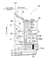
도 3, 도 4는, 변속기 케이스(10)에 있어서의 변속기 컨트롤러(9)의 배치의 변형예를 설명하는 도면이다.Figs. 3 and 4 are views for explaining a modification of the arrangement of the
상기한 실시 형태에서는, 구획벽부(12)의 제2 벽(122)과, 벽부(123)와, 팽출 영역(111a)과, 덮개부(126)로, 전동 오일 펌프(21)를 수용하는 제2 실(S2)(전동 오일 펌프실)을 형성한 경우를 예시하였다.In the above-described embodiment, the
도 3의 (a)에 도시하는 자동 변속기(1B)와 같이, 수평선 H1 방향에 있어서의 오목부(126a)의 깊이를 깊게 한 덮개부(126A)를 채용함으로써, 제2 벽(122)의 외주에 부설한 덮개부(126A)만으로 제2 실(S2)을 형성해도 된다.By adopting the
상기한 실시 형태에서는, 제2 실(S2) 내에 있어서 변속기 컨트롤러(9)를 덮개부(126)의 오목부(126a) 내에 설치한 경우를 예시하였다.In the above embodiment, the case where the
도 4에 도시하는 자동 변속기(1C)와 같이, 변속기 컨트롤러(9)를 연직선 방향에 있어서의 팽출 영역(111a)의 상측면(111b)에 설치한 구성으로 하여도 된다.The
이 경우에는, 변속기 컨트롤러(9)가 덮개부(126)의 오목부(126a) 내에 설치되어 있는 경우보다도, 변속기 컨트롤러(9)를 컨트롤 밸브 유닛(17)에 근접하여 배치할 수 있다.In this case, the
이에 의해, 와이어하니스(128)의 전체 길이를 더욱 짧게 할 수 있으므로, 와이어하니스(128)를 통하여 주고받아지는 신호(센서 신호, 명령)에 있어서의 에러의 발생을 억제할 수 있다.This makes it possible to further shorten the overall length of the
상기한 실시 형태에서는, 제2 실(S2)이, 전동 오일 펌프(21)를 수용하는 전동 오일 펌프실이며, 변속기 컨트롤러(9)(ATCU)를 이 전동 오일 펌프실에 수용한 경우를 예시하였다.In the above embodiment, the second chamber S2 is an electric oil pump chamber for accommodating the
변속기 컨트롤러(9)를 설치하는 장소는, 제2 실(S2)에 한정되는 것은 아니다. 예를 들어, 컨트롤 밸브 유닛(17)이나 오일 필터(201) 등의 자동 변속기가 구비하는 다른 부품을 수용하는 수용실이어도 된다.The place where the
도 5는, 변속기 케이스(10)에 있어서의 변속기 컨트롤러(9)의 배치의 변형예를 설명하는 도면이며, 변속기 컨트롤러(9)를 제3 실(S3)(컨트롤 밸브 유닛실)에 배치한 경우를 설명하는 도면이다.5 is a view for explaining a modification of the arrangement of the
도 5에 도시한 바와 같이, 이 자동 변속기(1C)에서는, 변속기 컨트롤러(9)를 수용하기 위한 오목부(151)가 오일 팬(15)에 설치되어 있다.5, in the
변속기 컨트롤러(9)는 오목부(151)에 배치된 상태에서, 제3 실(S3)(컨트롤 밸브 유닛실) 내에 배치되어 있다. 변속기 컨트롤러(9)는 오목부(151)에 수용된 상태에서, 오일 팬(15)에 있어서의 위치 어긋남이 방지되어 있다.The
즉, 자동 변속기(1C)는, 이하의 구성을 갖고 있다.That is, the
(15) 변속 기구가 배치된 제1 실(S1)과,(15) a first chamber (S1) in which a transmission mechanism is disposed,
전동 오일 펌프(21)가 배치되는 제2 실(S2)과,A second chamber S2 in which the
컨트롤 밸브 유닛(17)이 배치되는 제3 실(S3)을 갖는다.And a third chamber S3 in which the
제3 실(S3)은, 변속기 케이스(10)의 하부에 설치되는 오일 팬(15)(덮개부)의 내측에 형성되어 있다.The third chamber S3 is formed inside the oil pan 15 (lid portion) provided at the lower portion of the
변속기 컨트롤러(9)는 오일 팬(15)에 설치되어 있다.The
이렇게 구성하면, 기존의 오일 팬(15)에 변속기 컨트롤러(9)가 설치되어 있기 때문에, 변속기 컨트롤러(9)를 설치하기 위해서, 오일 팬(15) 주위의 큰 설계 변경을 필요로 하지 않는다.In this case, since the
특히, 오일 팬(15)에 설치한 오목부(151)에 변속기 컨트롤러(9)를 설치하는 구성으로 했으므로, 변속기 컨트롤러(9)를 기존의 오일 팬(15)에 설치함에 있어서, 별도 부품을 필요로 하지 않는다.Particularly, since the
따라서, 부품 개수의 증가에 의한 제작 비용의 상승을 적합하게 방지하면서, 변속기 컨트롤러(9)와 컨트롤 밸브 유닛(17)을 짧은 거리로 접속할 수 있다.Therefore, it is possible to connect the
또한, 변속기 컨트롤러(9)가 컨트롤 밸브 유닛(17)에 더욱 근접하여 배치되므로, 와이어하니스(128)의 전체 길이를 보다 짧게 할 수 있다.Further, since the
이에 의해, 와이어하니스(128)의 전기 저항 저감이 가능해져서, 와이어하니스(128)를 통하여 주고받아지는 신호(센서 신호, 명령)에 있어서의 에러의 발생을 억제할 수 있다. 또한, 와이어하니스(128)의 전체 길이가 짧아진 만큼, 비용의 저감이 가능해진다.As a result, the electrical resistance of the
또한, 도 5의 자동 변속기(1C) 경우에는, 상기한 자동 변속기의 제조 방법은, 이하와 같이 특정할 수 있다In the case of the
(16) 자동 변속기는, 변속 기구가 배치된 제1 실(S1)(변속 기구실)과,(16) The automatic transmission includes a first chamber S1 (transmission mechanism chamber) in which a transmission mechanism is disposed,
전동 오일 펌프(21)가 배치되는 제2 실(S2)과,A second chamber S2 in which the
컨트롤 밸브 유닛(17)이 배치되는 제3 실(S3)을 갖는다.And a third chamber S3 in which the
제3 실(S3)은, 변속기 케이스(10)의 하부에 고정한 오일 팬(15)의 내측에 형성된다. 변속기 컨트롤러(9)는 오일 팬(15)에 설치되어 있다.The third chamber (S3) is formed inside the oil pan (15) fixed to the lower portion of the transmission case (10). The
자동 변속기(1C)는, 변속기 컨트롤러(9)로부터 연장하는 와이어하니스(128)를 컨트롤 밸브 유닛(17)에 접속한 후, 컨트롤 밸브 유닛(17)을 제3 실(S3)로 변속기 케이스(10)의 하부에 고정하고, 변속기 컨트롤러(9)가 설치된 오일 팬(15)을 변속기 케이스(10)에 설치하고, 변속기 케이스(10)의 하부 개구(16)를 오일 팬(15)으로 막아서 제3 실(S3)을 형성함으로써 제작된다.The
이렇게 구성하면, 컨트롤 밸브 유닛(17)(다른 부재)과 변속기 컨트롤러(9)를 동시에 설치할 때는, 오일 팬(15)(덮개부)을 후에 설치함으로써 조립이 용이해진다.With such a configuration, when the control valve unit 17 (another member) and the
변속기 컨트롤러(9)를 설치함에 있어서, 별도 부품이 필요없으므로, 제작 비용의 상승을 적합하게 억제할 수 있다.In the case of installing the
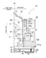
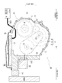
도 6은, 변속기 컨트롤러(9)의 변속기 케이스(10)에 있어서의 배치의 변형예를 설명하는 도면이며, 연직선 방향에 있어서의 구획벽부(12)의 상부에 오일 쿨러(20)가 설치되어 있는 자동 변속기(1D)의 경우를 설명하는 도면이다.6 is a view for explaining a modified example of the arrangement of the
자동 변속기(1D)의 변속기 케이스(10)의 구획벽부(12)에서는, 연직선 방향에 있어서의 제1 벽(121)의 상부에, 오일 쿨러(20)가 설치되어 있다.The
제1 벽(121)은 오일 팬(15)측의 제2 벽(122)보다도 수평선 H2 방향의 두께가 두껍게 되어 있다.The thickness of the
제1 벽(121)에는, 오일 필터(201)의 수용부(121c)가 설치되어 있다. 수용부(121c)는 수평선 H2 방향을 따르는 방향에서 설치되어 있다. 오일 필터(201)는 수평선 H2 방향에 있어서의 차량 전방측으로부터, 수용부(121c)에 대하여 탈착된다.A receiving
자동 변속기(1D)의 경우에도, 오일 쿨러(20)로 식혀진 오일(OL)이, 오일 필터(201)를 통하여, 제1 실(S1)측으로 복귀된다.The oil OL cooled in the
구획벽부(12)에서는, 차량 전방측의 표면에, 수용부(121c)의 개구를 막기 위한 덮개부(126)가 설치되어 있다.In the
덮개부(126)는 구획벽부(12)와의 대향면에 오목부(126a)를 갖고 있으며, 이 오목부(126a) 내에 변속기 컨트롤러(9)가 수용되어 있다.The
또한, 덮개부(126)의 표면에는, 커넥터(도시하지 않음)가 설치되어 있고, 변속기 컨트롤러(9)는 커넥터(127)에 접속된 외부 배선을 통하여, 차량에 탑재된 다른 제어 장치(예를 들어, 엔진 컨트롤 유닛)에 접속되어 있다.A connector (not shown) is provided on the surface of the
덮개부(126)는 제1 벽(121)과 제2 벽(122)에 걸쳐서 설치되어 있다. 그리고 구획벽부(12)와 덮개부(126)의 오목부(126a) 사이의 영역이, 오일 필터(201)를 외부로부터 구획하기 위한 필터실(제4 실(S4))로 되어 있다.The
제2 벽(122)에 있어서의 덮개부(126)에 대향하는 영역에는, 제4 실(필터실)(S4)과 제3 실(S3)을 연통하는 연통 구멍(130)이 개구되어 있다.A communicating
변속기 컨트롤러(9)로부터 연장하는 와이어하니스(128)는 연통 구멍(130)을 통하여, 제3 실(S3) 내에 인출되어 있고, 제3 실(S3) 내로 컨트롤 밸브 유닛(17)에 접속되어 있다.The
또한, 자동 변속기(1D)에서는, 오일 필터(201)는 제4 실(S4)에 배치되어 있고, 오일 쿨러(20)에 관계하는 부재인 덮개부(126)를 제4 실(S4)의 덮개로서 사용하고 있다.In the
오일 쿨러(20)를 전동 오일 펌프(21)보다도 약간 멀리 떨어지게 함으로써, 오일 필터(201)를 배치하는 스페이스를 확보할 수 있다. 이에 의해, 오일 필터(201)를 오일 쿨러(20)의 근처에 배치할 수 있다. 따라서, 오일 필터(201)와 오일 쿨러(20)를 연통시키는 긴 튜브가 불필요해져, 부품 개수를 감소시킬 수 있다.By making the
이상과 같이, 자동 변속기(1D)는, 이하의 구성을 갖고 있다.As described above, the
(17) 변속 기구가 배치된 제1 실(S1)과,(17) a first chamber S1 in which a transmission mechanism is disposed,
전동 오일 펌프(21)가 배치되는 제2 실(S2)과,A second chamber S2 in which the
오일 쿨러(20)의 오일 필터(201)의 필터실이 되는 제4 실(S4)과,A fourth chamber S4 serving as a filter chamber of the
제4 실(S4)의 적어도 일부를 구성하는 덮개부(126)를 갖고,And a
변속기 컨트롤러(9)는 덮개부(126)에 탑재되어 있다.The
이렇게 구성하면, 오일 필터(201)의 기존의 필터실(수용실)을 구획 형성하는 덮개부(126)에, 변속기 컨트롤러(9)를 설치했으므로, 변속기 컨트롤러(9)를 오일 필터(201)의 수용실인 제4 실(S4)에 설치함에 있어서, 별도 부품을 필요로 하지 않는다. 그 때문에, 변속기 컨트롤러(9)의 설치 위한 비용 상승을 적합하게 억제할 수 있다.The
이 경우에는, 상기한 자동 변속기의 제조 방법은, 이하와 같이 특정할 수 있다.In this case, the above-described automatic transmission manufacturing method can be specified as follows.
(18) 자동 변속기는, 변속 기구가 배치된 제1 실(S1)(변속 기구실)과,(18) The automatic transmission includes a first chamber S1 (transmission mechanism chamber) in which a transmission mechanism is disposed,
전동 오일 펌프(21)가 배치되는 제2 실(S2)과,A second chamber S2 in which the
오일 필터(201)의 수용실인 제4 실(S4)과,A fourth chamber S4 serving as a storage chamber of the
제4 실(S4)의 적어도 일부를 구성하는 덮개부(126)를 갖는다.And a
변속기 컨트롤러(9)는 덮개부(126)에 탑재되어 있다.The
자동 변속기는, 오일 필터(201)를 제4 실(S4) 내에 배치한 후, 변속기 컨트롤러(9)가 설치된 덮개부(126)를 설치함으로써 제작된다.The automatic transmission is manufactured by disposing the
이렇게 구성하면, 오일 필터(201)(다른 부재)와 변속기 컨트롤러(9)를 동시에 설치할 때는, 덮개부(126)를 후에 설치함으로써 조립이 용이해진다.With this configuration, when the oil filter 201 (another member) and the
오일 쿨러(20)측의 부품에, 변속기 컨트롤러(9) 및/또는 커넥터를 탑재함으로써, 부품 개수를 삭감할 수 있으므로 바람직하다.It is preferable because the number of parts can be reduced by mounting the
상기한 실시 형태에서는, 벨트식의 무단 변속 기구의 경우를 예시했지만, 차량용의 벨트식의 자동 변속기(1)(CVT)의 동력 전달 부재(5)는 프라이머리 풀리(3)와 세컨더리 풀리(4) 사이에서 회전을 전달 가능한 것이기만 하면 된다.The
따라서, 무단 변속기는 체인식의 무단 변속 기구여도 된다.Therefore, the continuously variable transmission may be a continuously variable transmission mechanism of the body recognition.
이상, 본원 발명의 실시 형태를 설명했지만, 본원 발명은, 이들 실시 형태에 나타낸 양태에만 한정되는 것은 아니다. 발명이 기술적인 사상의 범위 내에서, 적절히 변경 가능하다.Although the embodiment of the present invention has been described above, the present invention is not limited to the embodiment shown in these embodiments. The invention is suitably modified within the scope of technical thought.
1, 1A∼1D: 자동 변속기
10: 변속기 케이스
11: 주위벽
111: 구획벽
111a: 팽출 영역
111b: 상측면
112: 연통 구멍
112a: 표면
12: 구획벽부
121: 제1 벽
121a: 표면
121b: 수용부
121c: 수용부
122: 제2 벽
122a: 표면
123: 벽부
126, 126A: 덮개부
126a: 오목부
127: 커넥터
128: 와이어하니스
129: 유로
130: 연통 구멍
15: 오일 팬
151: 오목부
16: 개구
17: 컨트롤 밸브 유닛
18: 오일 스트레이너
2: 배리에이터
20: 오일 쿨러
20a: 단부
21: 전동 오일 펌프
21a: 단부
201: 오일 필터
3: 프라이머리 풀리
31: 프라이머리 풀리축
4: 세컨더리 풀리
41: 세컨더리 풀리축
5: 동력 전달 부재(벨트)
6: 기어 열
7: 파이널 기어
8: 차동 장치
9: 변속기 컨트롤러
H1, H2: 수평선
OL: 오일(작동유)
RAD: 라디에이터
S1: 제1 실
S2: 제2 실
S3: 제3실
S4: 제4 실
V1, V2: 연직선
X1, X2: 회전축1, 1A-1D: Automatic transmission
10: Transmission case
11: surrounding wall
111: compartment wall
111a: bulge region
111b:
112: communicating hole
112a: surface
12:
121: first wall
121a: surface
121b:
121c:
122: second wall
122a: surface
123: wall portion
126, 126A:
126a:
127: Connector
128: Wire harness
129: Euro
130: communicating hole
15: Oil pan
151:
16: aperture
17: Control valve unit
18: Oil Strainer
2: Variator
20: Oil cooler
20a: end
21: Electric oil pump
21a: end
201: Oil filter
3: primary pulley
31: primary pulley shaft
4: Secondary pulley
41: Secondary pulley shaft
5: Power transmission member (belt)
6: Gear column
7: Final gear
8: Differential
9: Transmission controller
H1, H2: Horizontal line
OL: Oil (hydraulic oil)
RAD: Radiator
S1: 1st room
S2: Second room
S3: Third room
S4: Fourth room
V1, V2: vertical line
X1, X2:
Claims (3)
변속기 컨트롤러가 배치되는 제2 실과,
상기 제2 실의 적어도 일부를 구성하는 덮개부를 갖고,
상기 변속기 컨트롤러는 상기 덮개부에 탑재되어 있는 것을 특징으로 하는, 자동 변속기.A first chamber in which a transmission mechanism is disposed,
A second chamber in which a transmission controller is disposed,
And a lid portion constituting at least a part of the second chamber,
And the transmission controller is mounted on the cover portion.
상기 변속기 컨트롤러와 접속되는 커넥터를 갖고,
상기 커넥터는 상기 덮개부에 탑재되어 있는 것을 특징으로 하는, 자동 변속기.The method according to claim 1,
And a connector connected to the transmission controller,
And the connector is mounted on the lid portion.
변속기 컨트롤러 및 전동 오일 펌프가 배치되는 제2 실과,
상기 제2 실의 일부를 구성하는 덮개부를 갖는 자동 변속기의 제조 방법이며,
상기 전동 오일 펌프를 상기 제2 실 내에 배치한 후, 상기 변속기 컨트롤러가 탑재된 상기 덮개부를 설치하는 것을 특징으로 하는, 자동 변속기의 제조 방법.A first chamber in which a transmission mechanism is disposed,
A second chamber in which the transmission controller and the electric oil pump are disposed,
And a lid portion constituting a part of the second chamber,
And the lid portion on which the transmission controller is mounted is provided after the electric oil pump is disposed in the second chamber.
Applications Claiming Priority (2)
| Application Number | Priority Date | Filing Date | Title |
|---|---|---|---|
| JP2017138494A JP6910717B2 (en) | 2017-07-14 | 2017-07-14 | Automatic transmission and manufacturing method of automatic transmission |
| JPJP-P-2017-138494 | 2017-07-14 |
Publications (1)
| Publication Number | Publication Date |
|---|---|
| KR20190008094A true KR20190008094A (en) | 2019-01-23 |
Family
ID=65048687
Family Applications (1)
| Application Number | Title | Priority Date | Filing Date |
|---|---|---|---|
| KR1020180075440A KR20190008094A (en) | 2017-07-14 | 2018-06-29 | Automatic transmission, and manufacturing method for automatic transmission |
Country Status (3)
| Country | Link |
|---|---|
| JP (1) | JP6910717B2 (en) |
| KR (1) | KR20190008094A (en) |
| CN (2) | CN109253221B (en) |
Citations (1)
| Publication number | Priority date | Publication date | Assignee | Title |
|---|---|---|---|---|
| JP2009174668A (en) | 2008-01-28 | 2009-08-06 | Hitachi Ltd | Electronic control device |
Family Cites Families (12)
| Publication number | Priority date | Publication date | Assignee | Title |
|---|---|---|---|---|
| JPH01312252A (en) * | 1988-06-08 | 1989-12-18 | Jatco Corp | Electronically controlled automatic transmission |
| DE19604957A1 (en) * | 1996-02-10 | 1997-08-14 | Audi Ag | Automatic electrohydraulically controlled transmission |
| DE19710931B4 (en) * | 1996-03-27 | 2007-08-16 | Volkswagen Ag | Automatic transmission with integrated control electronics |
| DE19950967A1 (en) * | 1999-10-22 | 2001-05-10 | Voith Turbo Kg | Gear unit and control platform for use in a gear unit |
| CN2685660Y (en) * | 2004-02-09 | 2005-03-16 | 广州市海星马电动车有限公司 | Built-in electrodynamic drive box |
| DE102009014595A1 (en) * | 2009-03-24 | 2010-09-30 | Magna Powertrain Ag & Co Kg | gear unit |
| JP2011032980A (en) * | 2009-08-05 | 2011-02-17 | Jtekt Corp | Motor-driven pump unit for transmission |
| DE102011088031A1 (en) * | 2011-12-08 | 2013-06-13 | Robert Bosch Gmbh | Transmission control module |
| JP5761086B2 (en) * | 2012-03-12 | 2015-08-12 | トヨタ自動車株式会社 | vehicle |
| CN202545772U (en) * | 2012-03-21 | 2012-11-21 | 徐工集团工程机械股份有限公司科技分公司 | Arrangement structure of external oil pipe of electronic control transmission |
| JP6245109B2 (en) * | 2014-08-11 | 2017-12-13 | スズキ株式会社 | Automatic transmission |
| JP2016053309A (en) * | 2014-09-03 | 2016-04-14 | 日立オートモティブシステムズ株式会社 | Electric oil pump combined with automatic transmission |
-
2017
- 2017-07-14 JP JP2017138494A patent/JP6910717B2/en active Active
-
2018
- 2018-06-29 KR KR1020180075440A patent/KR20190008094A/en not_active Application Discontinuation
- 2018-07-13 CN CN201810769702.4A patent/CN109253221B/en active Active
- 2018-07-13 CN CN201910782287.0A patent/CN110513459B/en active Active
Patent Citations (1)
| Publication number | Priority date | Publication date | Assignee | Title |
|---|---|---|---|---|
| JP2009174668A (en) | 2008-01-28 | 2009-08-06 | Hitachi Ltd | Electronic control device |
Also Published As
| Publication number | Publication date |
|---|---|
| JP6910717B2 (en) | 2021-07-28 |
| CN110513459B (en) | 2023-03-24 |
| CN110513459A (en) | 2019-11-29 |
| CN109253221B (en) | 2022-03-25 |
| JP2019019888A (en) | 2019-02-07 |
| CN109253221A (en) | 2019-01-22 |
Similar Documents
| Publication | Publication Date | Title |
|---|---|---|
| JP6423403B2 (en) | Oil passage structure of power transmission device | |
| JP5707656B2 (en) | Vehicle drive device | |
| US7651425B2 (en) | Vehicular power transmitting apparatus | |
| JP6187595B2 (en) | Vehicle drive device | |
| KR102113129B1 (en) | Automatic transmission | |
| CN111656055B (en) | Power transmission device | |
| KR20190008093A (en) | Automatic transmission | |
| JP2016055836A (en) | Drive device for vehicle | |
| US20230044400A1 (en) | Power transmission device | |
| KR20190008094A (en) | Automatic transmission, and manufacturing method for automatic transmission | |
| JP4574511B2 (en) | Vehicle differential device | |
| JP2019124341A (en) | Power transmission device | |
| WO2023182455A1 (en) | Power transmission device | |
| WO2023182451A1 (en) | Power transmission device | |
| WO2023182447A1 (en) | Power transmission device | |
| WO2023182450A1 (en) | Power transmission device | |
| JP2023141341A (en) | power transmission device | |
| WO2020084990A1 (en) | Housing member for power transmission device | |
| WO2023182456A1 (en) | Power transmission device | |
| WO2023171051A1 (en) | Device | |
| WO2023182453A1 (en) | Power transmission device | |
| US11859707B2 (en) | Power transmission device | |
| JP6089720B2 (en) | Hydraulic control device | |
| JP2010150977A (en) | Oil pump device for automatic transmission |
Legal Events
| Date | Code | Title | Description |
|---|---|---|---|
| A201 | Request for examination | ||
| E902 | Notification of reason for refusal | ||
| E902 | Notification of reason for refusal | ||
| E90F | Notification of reason for final refusal | ||
| E601 | Decision to refuse application |