KR20180031810A - Selective high frequency spinal cord modulation for inhibiting pain with reduced side effects, and associated systems and methods - Google Patents
Selective high frequency spinal cord modulation for inhibiting pain with reduced side effects, and associated systems and methods Download PDFInfo
- Publication number
- KR20180031810A KR20180031810A KR1020187007678A KR20187007678A KR20180031810A KR 20180031810 A KR20180031810 A KR 20180031810A KR 1020187007678 A KR1020187007678 A KR 1020187007678A KR 20187007678 A KR20187007678 A KR 20187007678A KR 20180031810 A KR20180031810 A KR 20180031810A
- Authority
- KR
- South Korea
- Prior art keywords
- patient
- pain
- patients
- signal
- treatment
- Prior art date
Links
Images


Classifications
-
- A—HUMAN NECESSITIES
- A61—MEDICAL OR VETERINARY SCIENCE; HYGIENE
- A61N—ELECTROTHERAPY; MAGNETOTHERAPY; RADIATION THERAPY; ULTRASOUND THERAPY
- A61N1/00—Electrotherapy; Circuits therefor
- A61N1/18—Applying electric currents by contact electrodes
- A61N1/32—Applying electric currents by contact electrodes alternating or intermittent currents
- A61N1/36—Applying electric currents by contact electrodes alternating or intermittent currents for stimulation
- A61N1/3605—Implantable neurostimulators for stimulating central or peripheral nerve system
- A61N1/3606—Implantable neurostimulators for stimulating central or peripheral nerve system adapted for a particular treatment
- A61N1/36071—Pain
-
- A—HUMAN NECESSITIES
- A61—MEDICAL OR VETERINARY SCIENCE; HYGIENE
- A61N—ELECTROTHERAPY; MAGNETOTHERAPY; RADIATION THERAPY; ULTRASOUND THERAPY
- A61N1/00—Electrotherapy; Circuits therefor
- A61N1/02—Details
- A61N1/04—Electrodes
- A61N1/05—Electrodes for implantation or insertion into the body, e.g. heart electrode
- A61N1/0551—Spinal or peripheral nerve electrodes
- A61N1/0553—Paddle shaped electrodes, e.g. for laminotomy
-
- A—HUMAN NECESSITIES
- A61—MEDICAL OR VETERINARY SCIENCE; HYGIENE
- A61N—ELECTROTHERAPY; MAGNETOTHERAPY; RADIATION THERAPY; ULTRASOUND THERAPY
- A61N1/00—Electrotherapy; Circuits therefor
- A61N1/02—Details
- A61N1/04—Electrodes
- A61N1/06—Electrodes for high-frequency therapy
-
- A—HUMAN NECESSITIES
- A61—MEDICAL OR VETERINARY SCIENCE; HYGIENE
- A61N—ELECTROTHERAPY; MAGNETOTHERAPY; RADIATION THERAPY; ULTRASOUND THERAPY
- A61N1/00—Electrotherapy; Circuits therefor
- A61N1/18—Applying electric currents by contact electrodes
- A61N1/32—Applying electric currents by contact electrodes alternating or intermittent currents
- A61N1/323—Interference currents, i.e. treatment by several currents summed in the body
-
- A—HUMAN NECESSITIES
- A61—MEDICAL OR VETERINARY SCIENCE; HYGIENE
- A61N—ELECTROTHERAPY; MAGNETOTHERAPY; RADIATION THERAPY; ULTRASOUND THERAPY
- A61N1/00—Electrotherapy; Circuits therefor
- A61N1/18—Applying electric currents by contact electrodes
- A61N1/32—Applying electric currents by contact electrodes alternating or intermittent currents
- A61N1/36—Applying electric currents by contact electrodes alternating or intermittent currents for stimulation
- A61N1/36014—External stimulators, e.g. with patch electrodes
- A61N1/36021—External stimulators, e.g. with patch electrodes for treatment of pain
-
- A—HUMAN NECESSITIES
- A61—MEDICAL OR VETERINARY SCIENCE; HYGIENE
- A61N—ELECTROTHERAPY; MAGNETOTHERAPY; RADIATION THERAPY; ULTRASOUND THERAPY
- A61N1/00—Electrotherapy; Circuits therefor
- A61N1/18—Applying electric currents by contact electrodes
- A61N1/32—Applying electric currents by contact electrodes alternating or intermittent currents
- A61N1/36—Applying electric currents by contact electrodes alternating or intermittent currents for stimulation
- A61N1/3605—Implantable neurostimulators for stimulating central or peripheral nerve system
- A61N1/3606—Implantable neurostimulators for stimulating central or peripheral nerve system adapted for a particular treatment
- A61N1/36062—Spinal stimulation
-
- A—HUMAN NECESSITIES
- A61—MEDICAL OR VETERINARY SCIENCE; HYGIENE
- A61N—ELECTROTHERAPY; MAGNETOTHERAPY; RADIATION THERAPY; ULTRASOUND THERAPY
- A61N1/00—Electrotherapy; Circuits therefor
- A61N1/18—Applying electric currents by contact electrodes
- A61N1/32—Applying electric currents by contact electrodes alternating or intermittent currents
- A61N1/36—Applying electric currents by contact electrodes alternating or intermittent currents for stimulation
- A61N1/3605—Implantable neurostimulators for stimulating central or peripheral nerve system
- A61N1/3606—Implantable neurostimulators for stimulating central or peripheral nerve system adapted for a particular treatment
- A61N1/36071—Pain
- A61N1/36075—Headache or migraine
-
- A—HUMAN NECESSITIES
- A61—MEDICAL OR VETERINARY SCIENCE; HYGIENE
- A61N—ELECTROTHERAPY; MAGNETOTHERAPY; RADIATION THERAPY; ULTRASOUND THERAPY
- A61N1/00—Electrotherapy; Circuits therefor
- A61N1/18—Applying electric currents by contact electrodes
- A61N1/32—Applying electric currents by contact electrodes alternating or intermittent currents
- A61N1/36—Applying electric currents by contact electrodes alternating or intermittent currents for stimulation
- A61N1/3605—Implantable neurostimulators for stimulating central or peripheral nerve system
- A61N1/3606—Implantable neurostimulators for stimulating central or peripheral nerve system adapted for a particular treatment
- A61N1/36082—Cognitive or psychiatric applications, e.g. dementia or Alzheimer's disease
- A61N1/36089—Addiction or withdrawal from substance abuse such as alcohol or drugs
-
- A—HUMAN NECESSITIES
- A61—MEDICAL OR VETERINARY SCIENCE; HYGIENE
- A61N—ELECTROTHERAPY; MAGNETOTHERAPY; RADIATION THERAPY; ULTRASOUND THERAPY
- A61N1/00—Electrotherapy; Circuits therefor
- A61N1/18—Applying electric currents by contact electrodes
- A61N1/32—Applying electric currents by contact electrodes alternating or intermittent currents
- A61N1/36—Applying electric currents by contact electrodes alternating or intermittent currents for stimulation
- A61N1/3605—Implantable neurostimulators for stimulating central or peripheral nerve system
- A61N1/36128—Control systems
- A61N1/36132—Control systems using patient feedback
-
- A—HUMAN NECESSITIES
- A61—MEDICAL OR VETERINARY SCIENCE; HYGIENE
- A61N—ELECTROTHERAPY; MAGNETOTHERAPY; RADIATION THERAPY; ULTRASOUND THERAPY
- A61N1/00—Electrotherapy; Circuits therefor
- A61N1/18—Applying electric currents by contact electrodes
- A61N1/32—Applying electric currents by contact electrodes alternating or intermittent currents
- A61N1/36—Applying electric currents by contact electrodes alternating or intermittent currents for stimulation
- A61N1/3605—Implantable neurostimulators for stimulating central or peripheral nerve system
- A61N1/36128—Control systems
- A61N1/36146—Control systems specified by the stimulation parameters
- A61N1/3615—Intensity
- A61N1/36157—Current
-
- A—HUMAN NECESSITIES
- A61—MEDICAL OR VETERINARY SCIENCE; HYGIENE
- A61N—ELECTROTHERAPY; MAGNETOTHERAPY; RADIATION THERAPY; ULTRASOUND THERAPY
- A61N1/00—Electrotherapy; Circuits therefor
- A61N1/18—Applying electric currents by contact electrodes
- A61N1/32—Applying electric currents by contact electrodes alternating or intermittent currents
- A61N1/36—Applying electric currents by contact electrodes alternating or intermittent currents for stimulation
- A61N1/3605—Implantable neurostimulators for stimulating central or peripheral nerve system
- A61N1/36128—Control systems
- A61N1/36146—Control systems specified by the stimulation parameters
- A61N1/3615—Intensity
- A61N1/3616—Voltage density or current density
-
- A—HUMAN NECESSITIES
- A61—MEDICAL OR VETERINARY SCIENCE; HYGIENE
- A61N—ELECTROTHERAPY; MAGNETOTHERAPY; RADIATION THERAPY; ULTRASOUND THERAPY
- A61N1/00—Electrotherapy; Circuits therefor
- A61N1/18—Applying electric currents by contact electrodes
- A61N1/32—Applying electric currents by contact electrodes alternating or intermittent currents
- A61N1/36—Applying electric currents by contact electrodes alternating or intermittent currents for stimulation
- A61N1/3605—Implantable neurostimulators for stimulating central or peripheral nerve system
- A61N1/36128—Control systems
- A61N1/36146—Control systems specified by the stimulation parameters
- A61N1/3615—Intensity
- A61N1/36164—Sub-threshold or non-excitatory signals
-
- A—HUMAN NECESSITIES
- A61—MEDICAL OR VETERINARY SCIENCE; HYGIENE
- A61N—ELECTROTHERAPY; MAGNETOTHERAPY; RADIATION THERAPY; ULTRASOUND THERAPY
- A61N1/00—Electrotherapy; Circuits therefor
- A61N1/18—Applying electric currents by contact electrodes
- A61N1/32—Applying electric currents by contact electrodes alternating or intermittent currents
- A61N1/36—Applying electric currents by contact electrodes alternating or intermittent currents for stimulation
- A61N1/3605—Implantable neurostimulators for stimulating central or peripheral nerve system
- A61N1/36128—Control systems
- A61N1/36146—Control systems specified by the stimulation parameters
- A61N1/36167—Timing, e.g. stimulation onset
- A61N1/36171—Frequency
-
- A—HUMAN NECESSITIES
- A61—MEDICAL OR VETERINARY SCIENCE; HYGIENE
- A61N—ELECTROTHERAPY; MAGNETOTHERAPY; RADIATION THERAPY; ULTRASOUND THERAPY
- A61N1/00—Electrotherapy; Circuits therefor
- A61N1/18—Applying electric currents by contact electrodes
- A61N1/32—Applying electric currents by contact electrodes alternating or intermittent currents
- A61N1/36—Applying electric currents by contact electrodes alternating or intermittent currents for stimulation
- A61N1/3605—Implantable neurostimulators for stimulating central or peripheral nerve system
- A61N1/36128—Control systems
- A61N1/36146—Control systems specified by the stimulation parameters
- A61N1/36167—Timing, e.g. stimulation onset
- A61N1/36175—Pulse width or duty cycle
-
- A—HUMAN NECESSITIES
- A61—MEDICAL OR VETERINARY SCIENCE; HYGIENE
- A61N—ELECTROTHERAPY; MAGNETOTHERAPY; RADIATION THERAPY; ULTRASOUND THERAPY
- A61N1/00—Electrotherapy; Circuits therefor
- A61N1/18—Applying electric currents by contact electrodes
- A61N1/32—Applying electric currents by contact electrodes alternating or intermittent currents
- A61N1/36—Applying electric currents by contact electrodes alternating or intermittent currents for stimulation
- A61N1/3605—Implantable neurostimulators for stimulating central or peripheral nerve system
- A61N1/36128—Control systems
- A61N1/36146—Control systems specified by the stimulation parameters
- A61N1/36167—Timing, e.g. stimulation onset
- A61N1/36178—Burst or pulse train parameters
-
- A—HUMAN NECESSITIES
- A61—MEDICAL OR VETERINARY SCIENCE; HYGIENE
- A61N—ELECTROTHERAPY; MAGNETOTHERAPY; RADIATION THERAPY; ULTRASOUND THERAPY
- A61N1/00—Electrotherapy; Circuits therefor
- A61N1/18—Applying electric currents by contact electrodes
- A61N1/32—Applying electric currents by contact electrodes alternating or intermittent currents
- A61N1/36—Applying electric currents by contact electrodes alternating or intermittent currents for stimulation
- A61N1/3605—Implantable neurostimulators for stimulating central or peripheral nerve system
- A61N1/36128—Control systems
- A61N1/36146—Control systems specified by the stimulation parameters
- A61N1/36182—Direction of the electrical field, e.g. with sleeve around stimulating electrode
-
- A—HUMAN NECESSITIES
- A61—MEDICAL OR VETERINARY SCIENCE; HYGIENE
- A61N—ELECTROTHERAPY; MAGNETOTHERAPY; RADIATION THERAPY; ULTRASOUND THERAPY
- A61N1/00—Electrotherapy; Circuits therefor
- A61N1/18—Applying electric currents by contact electrodes
- A61N1/32—Applying electric currents by contact electrodes alternating or intermittent currents
- A61N1/36—Applying electric currents by contact electrodes alternating or intermittent currents for stimulation
- A61N1/372—Arrangements in connection with the implantation of stimulators
- A61N1/37211—Means for communicating with stimulators
- A61N1/37235—Aspects of the external programmer
- A61N1/37241—Aspects of the external programmer providing test stimulations
-
- A—HUMAN NECESSITIES
- A61—MEDICAL OR VETERINARY SCIENCE; HYGIENE
- A61N—ELECTROTHERAPY; MAGNETOTHERAPY; RADIATION THERAPY; ULTRASOUND THERAPY
- A61N1/00—Electrotherapy; Circuits therefor
- A61N1/18—Applying electric currents by contact electrodes
- A61N1/32—Applying electric currents by contact electrodes alternating or intermittent currents
- A61N1/36—Applying electric currents by contact electrodes alternating or intermittent currents for stimulation
- A61N1/372—Arrangements in connection with the implantation of stimulators
- A61N1/37211—Means for communicating with stimulators
- A61N1/37235—Aspects of the external programmer
- A61N1/37247—User interfaces, e.g. input or presentation means
-
- A—HUMAN NECESSITIES
- A61—MEDICAL OR VETERINARY SCIENCE; HYGIENE
- A61N—ELECTROTHERAPY; MAGNETOTHERAPY; RADIATION THERAPY; ULTRASOUND THERAPY
- A61N1/00—Electrotherapy; Circuits therefor
- A61N1/18—Applying electric currents by contact electrodes
- A61N1/32—Applying electric currents by contact electrodes alternating or intermittent currents
- A61N1/36—Applying electric currents by contact electrodes alternating or intermittent currents for stimulation
- A61N1/372—Arrangements in connection with the implantation of stimulators
- A61N1/37211—Means for communicating with stimulators
- A61N1/37252—Details of algorithms or data aspects of communication system, e.g. handshaking, transmitting specific data or segmenting data
- A61N1/37264—Changing the program; Upgrading firmware
-
- A—HUMAN NECESSITIES
- A61—MEDICAL OR VETERINARY SCIENCE; HYGIENE
- A61N—ELECTROTHERAPY; MAGNETOTHERAPY; RADIATION THERAPY; ULTRASOUND THERAPY
- A61N1/00—Electrotherapy; Circuits therefor
- A61N1/18—Applying electric currents by contact electrodes
- A61N1/32—Applying electric currents by contact electrodes alternating or intermittent currents
- A61N1/36—Applying electric currents by contact electrodes alternating or intermittent currents for stimulation
- A61N1/372—Arrangements in connection with the implantation of stimulators
- A61N1/378—Electrical supply
- A61N1/3787—Electrical supply from an external energy source
-
- G—PHYSICS
- G01—MEASURING; TESTING
- G01R—MEASURING ELECTRIC VARIABLES; MEASURING MAGNETIC VARIABLES
- G01R21/00—Arrangements for measuring electric power or power factor
- G01R21/133—Arrangements for measuring electric power or power factor by using digital technique
-
- A—HUMAN NECESSITIES
- A61—MEDICAL OR VETERINARY SCIENCE; HYGIENE
- A61N—ELECTROTHERAPY; MAGNETOTHERAPY; RADIATION THERAPY; ULTRASOUND THERAPY
- A61N1/00—Electrotherapy; Circuits therefor
- A61N1/18—Applying electric currents by contact electrodes
- A61N1/32—Applying electric currents by contact electrodes alternating or intermittent currents
- A61N1/36—Applying electric currents by contact electrodes alternating or intermittent currents for stimulation
- A61N1/3605—Implantable neurostimulators for stimulating central or peripheral nerve system
Abstract
부작용이 감소되면서 통증을 억제하기 위한 선택적 고주파수 척수 조정, 및 관련된 시스템 및 방법이 개시된다. 특정 실시양태에서, 원치 않는 감각 및/또는 운동 부작용을 생성시키지 않으면서 허리 통증을 다루기 위해 약 1.5 KHz 내지 약 50 KHz 범위의 고주파수 조정이 환자의 척수 영역에 적용될 수 있다. 다른 실시양태에서, 유사한 파라메터에 따른 조정이 기타 적응증을 다루기 위해 기타 척추 또는 말초 위치에 적용될 수 있다.A selective high-frequency spinal adjustment for suppressing pain with reduced side effects, and related systems and methods are disclosed. In certain embodiments, high frequency adjustments in the range of about 1.5 KHz to about 50 KHz can be applied to the spinal cord area of the patient to handle back pain without creating unwanted sensations and / or motor side effects. In other embodiments, adjustments based on similar parameters may be applied to other vertebrae or peripheral locations to address other indications.
Description
관련 출원에 대한 교차 참조Cross-reference to related application
본 출원은 2009년 5월 8일 출원되고 본원에 참고로 포함된 미국 가출원 번호 61/176,868을 우선권으로 청구한다. 본 출원은 2009년 4월 22일 출원되고 본원에 참고로 포함된 미국 가출원 번호 61/171,790을 우선권으로 청구한다.This application claims priority to U.S. Provisional Application No. 61 / 176,868, filed May 8, 2009, which is incorporated herein by reference. This application claims priority to U.S. Provisional Application No. 61 / 171,790, filed April 22, 2009, which is incorporated herein by reference.
기술분야Technical field
일반적으로 본 개시내용은 부작용이 감소되면서 통증을 억제하기 위한 선택적 고주파수 척수 조정, 및 관련된 시스템 및 방법에 관한 것이다.In general, the present disclosure relates to selective high frequency spinal adjustment for inhibiting pain with reduced side effects, and related systems and methods.
배경기술Background technology
신경학적 자극물질이 통증, 운동 장애, 기능 장애, 경직, 암, 심장 장애, 및 다양한 기타 의학 용태를 치료하기 위해 개발되었다. 이식성(implantable) 자극 시스템에는 일반적으로 이식성 펄스 생성기, 및 전기적 펄스를 신경학적 조직 또는 근육 조직으로 전달하는 하나 이상의 도선이 있다. 예를 들어, 척수 자극 (SCS)을 위한 여러 신경학적 자극 시스템에는 원형 단면 형상의 도선체(lead body) 및 도선체의 윈위 끝부분에서의 서로 간격이 떨어진 하나 이상의 전도성 고리를 포함하는 원통형 도선이 있다. 전도성 고리는 개별적인 전극으로서 작용하고, 다수의 경우에, SCS 도선은, 속심(stylet)의 보조로 또는 속심의 보조 없이, 경막외공간 내로 삽입된 대형 바늘을 통해 피하 이식된다.Neurological stimulants have been developed to treat pain, movement disorders, dysfunctions, stiffness, cancer, cardiac disorders, and various other medical conditions. Implantable stimulation systems typically include an implantable pulse generator and one or more leads to deliver electrical pulses to neurological tissue or muscle tissue. For example, several neurological stimulation systems for spinal cord stimulation (SCS) include a lead body having a circular cross-sectional shape and a cylindrical lead comprising at least one conductive ring spaced apart at the distal end of the lead body have. The conductive rings act as individual electrodes and, in many cases, the SCS leads are implanted subcutaneously through the large needles inserted into the epidural space, with or without assistance of a stylet.
일단 이식되면, 펄스 생성기가 전기적 펄스를 전극에 적용하고, 차례로, 예컨대 감각 자극에 대한 환자의 응답을 변경시킴으로써 및/또는 환자의 운동 회로 출력을 변경시킴으로써, 전극이 환자의 신경계의 기능을 변형시킨다. 통증 치료에서, 펄스 생성기는 전기적 펄스를 전극에 적용하고, 차례로, 전극이 환자의 통증 감각을 차폐하거나 또는 다른 방식으로 변경시키는 감각을 생성시킬 수 있다. 예를 들어, 많은 경우에, 환자들이 기저를 이루는 통증 감각보다 더 좋고/좋거나 덜 불편한 것으로 지각되는 저림 또는 지각이상을 보고한다. 다수의 환자의 경우가 이러할 수 있는 한편, 다수의 다른 환자들은 덜 이로운 효과 및/또는 결과를 보고할 수 있다. 따라서, 환자 통증을 다루기 위한 개선된 기법 및 시스템이 여전히 요구된다.Once implanted, the pulse generator modifies the function of the patient ' s nervous system by applying electrical pulses to the electrodes and, in turn, by altering the patient ' s response to a sensory stimulation, and / . In the treatment of pain, the pulse generator may apply electrical pulses to the electrodes and, in turn, generate a sensation that shields or otherwise alters the patient ' s pain sensation. For example, in many cases, patients report a numbness or perception that is perceived as better / better or less uncomfortable than the baseline pain sensation. While this may be the case for many patients, many other patients may report less beneficial effects and / or results. Therefore, there is still a need for improved techniques and systems for dealing with patient pain.
도면의 간단한 설명
도 1a는 본 개시내용의 여러 실시양태에 따라 치료 신호를 전달하도록 척추에 놓인 이식성 척수 조정 시스템의 부분적인 개략도이다.
도 1b는 본 개시내용의 실시양태에 따른 이식된 도선체에 대한 대표적인 위치를 도해하는, 환자의 척추의 부분적인 단면 개략도이다.
도 2는 기저 수준 및 통상적인 척수 자극 장치로 달성된 수준과 비교된, 환자가 본 개시내용의 실시양태에 따른 치료법을 받은 임상 연구의 4일 기간에 걸친 환자에 대한 통증 감소 수준을 도해하는 막대 그래프이다.
도 3은 통상적인 척수 자극을 받은 환자에 대한 유사한 데이터와 비교된, 임상 연구 동안 본 개시내용의 실시양태에 따른 치료법을 받은 환자가 조정 변화를 개시한 횟수를 비교하는 막대 그래프이다.
도 4는 임상 연구 동안 수득된, 본 개시내용의 실시양태에 따른 치료법을 받은 환자에 대한 활동 수행 개선을 도해하는 막대 그래프이다.
도 5a는 임상 연구 동안 수득된, 다양한 활동을 수행하는 환자에 대한 활동 수행 수준을 비교하는 막대 그래프이다.
도 5b 및 5c는 임상 연구 동안 수득된, 본 개시내용의 실시양태에 따른 치료법을 받은 환자에 대한 수면 개선을 도해하는 막대 그래프이다.
도 6a는 임상 연구 동안 수득된, 본 개시내용의 실시양태에 따른 치료법을 받은 환자에 대한 조정 위치의 함수로서 성공적인 치료법 결과를 도해하는 막대 그래프이다.
도 6b 및 6c는 본 개시내용의 실시양태에 따라 수행된 방법을 도해하는 순서도이다.
도 7a는 본 개시내용의 실시양태에 따른 후속(follow-on) 임상 연구 동안에 사용된 도선의 배열을 도해한다.
도 7b는 본 개시내용의 실시양태에 따른 치료법을 받은 환자의 후속 임상 연구로부터 수득된 결과를 도해한다.
도 8은 통상적인 척수 자극에 대한 예상 작용 메커니즘과 비교된, 본 개시내용에 따른 치료법에 대한 가능한 작용 메커니즘을 확인하는 개략도이다.
도 9는 본 개시내용의 실시양태에 따라 형성된 도선의 부분적인 개략도이다.
도 10A-10C는 본 개시내용의 여러 실시양태에 따라 형성된 연장성(extendible) 도선의 부분적인 개략도이다.
도 11A-11C는 본 개시내용의 여러 실시양태에 따라 형성된 멀티파일러(multifilar) 도선의 부분적인 개략도이다. Brief Description of Drawings
1A is a partial schematic view of an implantable spinal cord adjustment system placed on the spine to deliver a therapeutic signal in accordance with various embodiments of the present disclosure;
1B is a partial cross-sectional schematic view of a patient's vertebrae illustrating an exemplary position for an implanted catheter according to an embodiment of the present disclosure;
Figure 2 is a bar chart illustrating the degree of pain reduction for a patient over a four day period of clinical study in which the patient received a treatment according to the baseline level and the level achieved with a conventional spinal cord stimulation device, Graph.
Figure 3 is a bar graph comparing the number of times a patient who received a treatment according to an embodiment of the present disclosure during a clinical study initiated an adjustment change compared to similar data for a patient who underwent conventional spinal cord stimulation.
Figure 4 is a bar graph illustrating improvement in activity performance for a patient who received treatment according to an embodiment of the present disclosure, obtained during a clinical study.
FIG. 5A is a bar graph comparing activity levels for patients performing various activities, obtained during clinical studies. FIG.
Figures 5b and 5c are bar graphs illustrating sleep improvements for patients who received treatment according to embodiments of the present disclosure, obtained during clinical studies.
6A is a bar graph illustrating the results of a successful treatment as a function of adjustment position for a patient who received treatment according to an embodiment of the present disclosure obtained during a clinical study.
Figures 6B and 6C are flowcharts illustrating a method performed in accordance with an embodiment of the present disclosure.
7A illustrates an array of leads used during a follow-on clinical study according to an embodiment of the present disclosure.
Figure 7b illustrates the results obtained from subsequent clinical studies of patients receiving treatment according to embodiments of the present disclosure.
Figure 8 is a schematic diagram that identifies a possible mechanism of action for a treatment according to this disclosure, as compared to the anticipatory action mechanism for conventional spinal cord stimulation.
9 is a partial schematic view of a wire formed in accordance with an embodiment of the present disclosure;
10A-10C are partial schematic views of an extendible wire formed in accordance with various embodiments of the present disclosure;
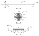
11A-11C are partial schematic views of multifilar conductors formed in accordance with various embodiments of the present disclosure.
상세한 설명details
1.0 개론 1.0 Introduction
일반적으로 본 발명의 기술은 일반적으로 부작용이 감소 또는 제거되면서 고주파수 요소 또는 성분 (예를 들어, 기본 주파수가 높은 부분)으로의 파형을 통해 통증을 억제하기 위한 척수 조정 및 관련된 시스템 및 방법에 관한 것이다. 이같은 부작용에는 원치 않는 운동 자극 또는 차단, 및/또는 표적 통증 이외의 감각 기능의 방해가 포함될 수 있다. 여러 실시양태들이 단순화된 척수 조정 시스템 및 성분, 및 진료의 및/또는 환자를 위한 단순화된 절차를 또한 제공한다. 본 개시내용의 특정 실시양태의 구체적인 상세사항들이 환자의 하나 이상의 표적 신경 집단 (예를 들어, 신경) 또는 부위를 조정하기 위한 방법, 및 이러한 조정을 제공하기 위한 관련된 이식성 구조물을 참조로 하기에 기술된다. 선택된 실시양태들이 통증을 제어하기 위해 척주, 후각, 후근, 후근 진입부, 및/또는 기타 특정 척주 영역을 조정하는 것과 관련하여 하기에 기술되지만, 일부 경우에 척수 및/또는 기타 신경학적 조직의 기타 신경학적 구조물 및/또는 표적 신경 집단에 조정이 지시될 수 있다. 일부 실시양태는 이러한 섹션에 기술된 것과 상이한 구성, 성분 또는 절차를 지닐 수 있고, 다른 실시양태는 특정 성분 또는 절차를 제거할 수 있다. 따라서, 관련 분야의 당업자는 본 개시내용이 추가적인 요소가 있는 다른 실시양태를 포함할 수 있고/있거나 도 1a-11C를 참조로 하기에 제시 및 기술된 특색들 중 몇몇이 없는 다른 실시양태를 포함할 수 있다는 것을 이해할 것이다.In general, the techniques of the present invention generally relate to spinal adjustment and associated systems and methods for suppressing pain through waveforms to high frequency components or components (e.g., high frequency portions) while side effects are reduced or eliminated . Such side effects may include unwanted movement stimulation or block, and / or disturbance of sensory function other than target pain. Various embodiments also provide a simplified spinal manipulation system and components, and simplified procedures for and / or patient care. Specific details of certain embodiments of the present disclosure may be found in a method for modulating one or more target neural populations (e.g., nerves) or regions of a patient, and related implantable structures for providing such adjustments, do. Although the selected embodiments are described below with reference to adjusting the spinal, olfactory, posterior, posterior access, and / or other specific spinal regions to control pain, in some cases the spinal cord and / or other Adjustment may be indicated to the neurological structure and / or the target neural population. Some embodiments may have configurations, components, or procedures that differ from those described in this section, and other embodiments may remove certain components or procedures. Accordingly, those skilled in the relevant art will appreciate that the present disclosure may include other embodiments in which there are additional elements and / or other embodiments that do not have some of the features presented and described below with reference to Figures IA-11C You will understand that you can.
일반적으로, 하기의 실시양태들 중 다수의 측면은 환자에서의 통증 감소를 포함하는 치료 효과를 일으키는 것에 관한 것이다. 이환된 신경 집단의 활성을 억제하거나, 저해하거나, 하향조절하거나, 차단하거나, 방지하거나, 또는 다른 방식으로 조정함으로써 치료 효과를 일으킬 수 있다. 본원에 개시된 기법들의 다수의 실시양태에서, 치료법-유도 지각이상은, 표준 SCS 기법과 달리, 통증 감소를 달성하기 위한 필요조건이 아니다. 도 1a-11C를 참조로 하기 기술된 기법은 기존의 척수 자극 치료법보다 더욱 효과적이고/이거나, 더욱 로버스트(robust)하고/하거나, 덜 복잡하고/하거나 다른 방식으로 더욱 바람직한 결과를 일으킬 수 있다.In general, many of the following embodiments relate to causing a therapeutic effect, including pain reduction in a patient. Can inhibit, inhibit, down-regulate, block, prevent, or otherwise modulate the activity of the affected neural population to produce a therapeutic effect. In many embodiments of the techniques disclosed herein, the therapy-induced tardive anomaly is not a requirement to achieve pain reduction, unlike the standard SCS technique. The techniques described below with reference to FIGS. 1A-11C may be more effective and / or more robust than conventional spinal cord stimulation therapies and / or may produce more desirable results in a less complex and / or otherwise manner.
도 1a는 환자의 척수 191의 일반적인 해부학적 구조와 관련하여 배열된, 만성 통증 및/또는 기타 용태로부터의 경감을 제공하기 위한 대표적인 치료 시스템 100을 개략적으로 도해한다. 시스템 100은 환자 190 내로 피하 이식될 수 있고 신호 전달 요소 110에 커플링될 수 있는 펄스 생성기 101을 포함할 수 있다. 대표적인 예에서, 신호 전달 요소 110은 이식 후 환자 190에게 치료법을 전달하기 위한 특색부를 보유하는 도선 또는 도선체 111을 포함한다. 펄스 생성기 101은 도선 111에 직접 연결될 수 있거나, 또는 통신 링크(link) 102 (예를 들어, 연장물)를 통해 도선 111에 커플링될 수 있다. 따라서, 도선 111은 브레이크(break) 114에서 연장물에 이탈식으로 연결된 말단 섹션을 포함할 수 있다 (도 1a에 개략적으로 제시됨). 이는 단일 유형의 말단 섹션이 상이한 체형 (예를 들어, 상이한 신장)의 환자에 사용될 수 있게 한다. 본원에서 사용된 용어 도선 및 도선체는 환자 190에게 치료법 신호를 제공하기 위한 장치를 보유하는 다수의 적절한 기판 및/또는 지지재 중 임의의 것을 포함한다. 예를 들어, 도선 111은, 예컨대 환자 경감을 제공하도록, 환자의 조직 내로 전기 신호를 지시하는 하나 이상의 전극 또는 전기 접점을 포함할 수 있다. 다른 실시양태에서, 신호 전달 요소 110은 환자 190에게 전기 신호 및/또는 기타 유형의 신호를 또한 지시하는, 도선체 이외의 장치 (예를 들어, 패들)을 포함할 수 있다.FIG. 1A schematically illustrates an
펄스 생성기 101은 표적 신경을 상향-조절 (예를 들어, 자극 또는 흥분시킴)하고/하거나, 하향-조절 (예를 들어, 차단 또는 억제함)하는 신호 (예를 들어, 전기 신호)를 신호 전달 요소 110에 전송할 수 있다. 달리 언급되지 않는 한, 본원에서 사용된 용어 "조정하다" 및 "조정"은 표적 신경에 대해 어느 한쪽 유형의 상기 효과가 있는 신호를 일반적으로 지칭한다. 펄스 생성기 101은 적절한 치료법 신호를 생성시키고 전송하기 위한 설명서를 함유하는 기계-판독가능 (예를 들어, 컴퓨터-판독가능) 매체를 포함할 수 있다. 시스템 100의 펄스 생성기 101 및/또는 기타 요소는 하나 이상의 프로세서 107, 메모리 108 및/또는 입력/출력 장치를 포함할 수 있다. 따라서, 조정 신호를 제공하고 기타 관련된 기능을 실행하기 위한 프로세스가 컴퓨터-판독가능 매체 상에, 예를 들어, 프로세서(들) 107 및/또는 메모리(들) 108에 함유된 컴퓨터-실행가능 설명서에 의해 수행될 수 있다. 펄스 생성기 101은 도 1a에 제시된 바와 같이 단일 하우징(housing) 내에 또는 다중 하우징 내에 수납된 다중 부분, 요소 및/또는 서브시스템을 포함할 수 있다 (예를 들어, 다중 신호 전달 파라메터에 따라 신호를 지시하기 위해).The
펄스 생성기 101은 또한 하나 이상의 공급원으로부터 수신된 입력 신호를 수신하여 이에 응답할 수 있다. 입력 신호는 치료법 설명서가 선택되고/되거나, 실행되고/되거나, 업데이트되고/되거나 다른 방식으로 수행되는 방식을 지시하거나 이에 영향을 미칠 수 있다. 입력 신호는 펄스 생성기 101이 보유하고/하거나 펄스 생성기 101 외부 (예를 들어, 다른 환자 위치)에 분포된 한편 여전히 펄스 생성기 101과 통신하는 하나 이상의 센서 112 (설명 목적을 위해 하나가 도 1에 개략적으로 제시됨)로부터 수신될 수 있다. 센서 112는 환자 상태 (예를 들어, 환자 위치, 환자 자세 및/또는 환자 활동 수준)에 좌우되거나 이를 반영하는 입력, 및/또는 환자-비의존적 입력 (예를 들어, 시간)을 제공할 수 있다. 다른 실시양태에서, 하기에 추가로 상세히 기술되는 바와 같이, 환자 및/또는 진료의에 의해 입력이 제공될 수 있다. 더욱 추가적인 상세사항이 2010년 2월 10일 출원되고 본원에 참고로 포함된, 공동 계류 중인 미국 출원 번호 12/703,683에 포함된다.The
일부 실시양태에서, 펄스 생성기 101은 외부 전력원 103으로부터 치료법 신호를 생성시키는 전력을 수득할 수 있다. 외부 전력원 103은 이식된 펄스 생성기 101에 전자기 유도 (예를 들어, RF 신호)를 사용하여 전력을 전송할 수 있다. 예를 들어, 외부 전력원 103은 이식성 펄스 생성기 101 내의 상응하는 내부 코일 (제시되지 않음)과 통신하는 외부 코일 104를 포함할 수 있다. 외부 전력원 103은 사용 편의를 위해 휴대가 가능할 수 있다.In some embodiments, the
또 다른 실시양태에서, 펄스 생성기 101은 외부 전력원 103에 더하여 또는 이를 대신하여 내부 전력원으로부터 치료법 신호를 생성시키는 전력을 수득할 수 있다. 예를 들어, 이식된 펄스 생성기 101이 이같은 전력을 제공하도록 재충전가능하지 않은 배터리 또는 재충전가능한 배터리를 포함할 수 있다. 내부 전력원이 재충전가능한 배터리를 포함하는 경우, 외부 전력원 103이 배터리를 재충전하는데 사용될 수 있다. 차례로 외부 전력원 103이 적절한 전력원 (예를 들어, 통상적인 벽 전력)으로부터 재충전될 수 있다.In another embodiment, the
일부 경우에, 펄스 생성기 101을 이식하기 전에, 초기 이식 절차 동안 신호 전달 요소 110에 외부 프로그래머 105 (예를 들어, 시험 조정기)가 커플링될 수 있다. 예를 들어, 진료의 (예를 들어, 의사 및/또는 회사 대표)가 외부 프로그래머 105를 사용하여, 실시간으로 신호 전달 요소 110에 제공되는 조정 파라메터를 변화시킬 수 있고, 최적이거나 특히 효과적인 파라메터를 선택할 수 있다. 이러한 파라메터에는 신호 전달 요소 110의 위치, 뿐만 아니라 신호 전달 요소 110에 제공되는 전기 신호의 특징이 포함될 수 있다. 전형적인 프로세스에서, 진료의는 케이블 어셈블리(cable assembly) 120을 사용하여 외부 프로그래머 105를 신호 전달 장치 110에 일시적으로 연결한다. 따라서 케이블 어셈블리 120은 외부 프로그래머 105에 이탈식으로 연결된 제1 연결기 121, 및 신호 전달 요소 110에 이탈식으로 연결된 제2 연결기 122를 포함할 수 있다. 따라서, 신호 전달 요소 110은 자신이 직접적으로 (충분히 긴 경우) 또는 간접적으로 (그렇지 않은 경우) 신호 생성기에 연결되도록 하는 연결 요소를 포함할 수 있다. 진료의는 초기 위치에서의 신호 전달 요소 110의 효능을 테스트할 수 있다. 그 후, 진료의가 케이블 어셈블리 120을 끊고, 신호 전달 요소 110을 다시 놓고, 전기적 조정을 다시 적용할 수 있다. 진료의가 신호 전달 장치 110에 대한 원하는 위치를 수득할 때까지, 이러한 프로세스가 반복적으로 수행될 수 있다. 임의적으로, 진료의가 부분적으로 이식된 신호 전달 요소 110을 케이블 어셈블리 120을 끊지 않으면서 이동시킬 수 있다. 적절한 케이블 어셈블리 방법 및 관련 기법의 추가적인 상세사항이 2009년 9월 18일 출원되고 본원에 참고로 포함된 공동 계류 중인 미국 출원 번호 12/562,892에 기술되어 있다. 하기에 추가로 상세히 논의될 바와 같이, 본 개시내용의 특정 측면은 상기 반복 프로세스를 유리하게 감소시키거나 제거할 수 있다.In some cases, prior to implanting the
신호 전달 요소 110의 위치 및 적합한 신호 전달 파라메터가 외부 프로그래머 105를 사용하여 확립된 후, 일반적으로 한정된 기간 동안, 외부 프로그래머 105에 의해 생성된 신호를 통해 환자 190이 치료법을 받을 수 있다. 대표적인 용도에서, 환자 190은 1주일 동안 이같은 치료법을 받는다. 이러한 시간 동안, 환자는 신체 외부에 케이블 어셈블리 120 및 외부 프로그래머 105를 착용한다. 시험 치료법이 효과적이거나 효과적일 전망을 나타낼 것으로 가정하면, 진료의는 외부 프로그래머 105를 이식된 펄스 생성기 101로 교체하고, 시험 기간 동안 수득된 경험을 기초로 선택된 파라메터로 펄스 생성기 101을 프로그래밍한다. 임의적으로, 진료의가 신호 전달 요소 110을 또한 교체할 수 있다. 이식성 펄스 생성기 101이 환자 190 내에 놓이면, 펄스 생성기 101이 제공하는 신호 전달 파라메터가 여전히 원격으로 의사의 무선 프로그래머 (예를 들어, 의사의 리모트(remote)) 111 및/또는 무선 환자 프로그래머 106 (예를 들어, 환자 리모트)을 통해 업데이트될 수 있다. 일반적으로, 환자 190은 진료의보다 더 적은 파라메터를 제어한다. 예를 들어, 환자 프로그래머 106의 능력은 펄스 생성기 101을 시작시키고/시키거나 정지시키는 것, 및/또는 신호 진폭을 조절하는 것에 한정될 수 있다. After the location of the
임의의 상기 실시양태에서, 펄스 생성기 101이 이에 따라 신호를 제공하는 파라메터가 치료법 계획의 일부 동안 조정될 수 있다. 예를 들어, 주파수, 진폭, 펄스 폭 및/또는 신호 전달 위치가 미리 설정된 프로그램, 환자 및/또는 의사의 입력에 따라, 및/또는 무작위 또는 유사-무작위 방식으로 조정될 수 있다. 이같은 파라메터 변경은 환자의 통증 인지에서의 변화, 바람직한 표적 신경 집단에서의 변화, 및/또는 환자 적응 또는 습관화가 포함되는 다수의 가능한 임상 상황을 다루는데 사용될 수 있다.In any of the above embodiments, the parameters by which the
상기 시스템 및 방법의 특정 측면이 본 개시내용의 특정 실시양태에서 단순화 또는 제거될 수 있다. 예를 들어, 적어도 일부 경우에, 시스템이 전달하는 치료 신호가 통상적인 자극 시스템보다 도선 위치 및 신호 전달 파라메터 (예를 들어, 진폭)에 훨씬 덜 민감한 효과를 일으킬 수 있다. 따라서, 상기 언급된 바와 같이, 도선 이식 절차 동안 적절한 도선 위치 및 관련된 신호 전달 파라메터를 확인하기 위한 시행착오 프로세스 (또는 이러한 프로세스의 일부분)가 제거될 수 있다. 이러한 단순화에 더하여 또는 이를 대신하여, 도선 이식 후 시험 기간이 제거될 수 있다. 상기 단순화에 더하여 또는 이를 대신하여, 신호 전달 파라메터를 선택하고 장기 기반으로 신호를 투여하는 프로세스가 유의하게 단순화될 수 있다. 이러한 이로운 결과 및 기타 예상되는 이로운 결과의 추가적인 측면들이 하기에서 더욱 상세하게 논의된다.Certain aspects of the systems and methods can be simplified or eliminated in certain embodiments of the present disclosure. For example, at least in some cases, the therapy signal delivered by the system may have a much less sensitive effect on the wire position and signal delivery parameters (e.g., amplitude) than a conventional stimulation system. Thus, as noted above, the trial and error process (or a portion of such a process) for identifying the appropriate lead position and associated signaling parameters during the wire implantation procedure can be eliminated. In addition to or in lieu of this simplification, the test period after the lead implantation can be eliminated. In addition to or in place of this simplification, the process of choosing the signaling parameters and administering the signal on a long term basis can be significantly simplified. Additional aspects of these beneficial results and other expected beneficial results are discussed in further detail below.
2.0 대표적인 치료법 파라메터 2.0 Typical Therapeutic Parameters
본 출원의 양수인인 네브로 코포레이션(Nevro Corporation)은 다수의 환자들이 먼저 통상적인 척수 자극 (SCS) 기법으로 치료된 후, 하기에 추가로 개시되는 새롭게 개발된 기법으로 치료된 멀티-사이트(multi-site) 임상 연구를 수행하였다. 이러한 연구에 새롭게 개발된 기법에 초점을 맞추는 추가적인 임상 연구가 이어졌고, 이는 초기 연구 동안 수득된 결과를 확증 및 확장시켰다. 새롭게 개발된 기법, 치료법 및/또는 시스템의 여러 실시양태는 본 발명에 개시된 기법, 치료법 및/또는 시스템으로, 더욱 일반적으로는 본 발명에 개시된 기술로 지칭된다.The assignee of the present application, Nevro Corporation, discloses that a large number of patients are first treated with a conventional spinal cord stimulation (SCS) technique and then treated with a newly developed technique, multi- site clinical studies. Additional clinical studies have focused on the newly developed techniques in these studies, confirming and extending the results obtained during the initial studies. Various embodiments of newly developed techniques, therapies, and / or systems are referred to as techniques, treatments, and / or systems disclosed herein, and more generally, techniques disclosed herein.
2.1. 초기 비교 연구 2.1. Initial comparative study
초기 임상 연구 전에, 선택된 환자들은 1차적인 만성 허리 통증 (예를 들어, 환자에 따라, 신경병증성 통증, 및/또는 침해성 통증, 및/또는 기타 유형의 통증)을 단독으로 또는 다른 부분, 전형적으로 환자의 다리(들)에 영향을 미치는 통증과 조합하여 앓고 있는 것으로 확인되었다. 모든 경우에, 허리 통증이 우세하였다. 연구 동안, 도 1a에 제시된 것과 일반적으로 유사한 방식으로 척추 영역 내에 각각 이식된 2개의 도선이 환자에게 장착되었다. 1개의 도선이 척수 정중선 189의 한쪽에 이식되었고, 또 다른 도선이 척수 정중선 189의 다른 쪽에 이식되었다. 도 1b는 도선 110이 대표적인 환자에 이식된 위치와 함께, 척수 191 및 인접한 척추뼈 195의 단면도이다 (일반적으로 문헌 [Crossman and Neary, "Neuroanatomy," 1995, Churchill Livingstone]으로부터의 정보를 기초로 함). 배쪽에 위치한 배쪽 몸체 196과 등쪽에 위치하는 가로 돌기 198 및 가시 돌기 197 사이에 척수 191이 위치한다. 화살표 V 및 D는 각각 배쪽 및 등쪽 방향을 나타낸다. 척수 191 자체는 경질막 199 내에 위치하고, 이는 후근 193 및 후근절 194가 포함되는, 척수 191에서 나가는 신경의 일부분을 또한 둘러싼다. 도선 110은 2개의 도선 110이 서로 약 2 ㎜만큼 떨어져 간격을 두도록 반대되는 측면 방향으로 척수 정중선 189를 약간 벗어나 위치하였다 (예를 들어, 약 1 ㎜ 오프셋(offset)).Prior to the initial clinical study, selected patients may be treated alone or in other portions with primary chronic back pain (e. G., Neuropathic pain and / or invasive pain, and / or other types of pain, Typically in combination with pain affecting the patient ' s leg (s). In all cases, back pain prevailed. During the study, two leads each implanted within the vertebral region were mounted to the patient in a manner generally similar to that shown in FIG. One wire was implanted on one side of the
도 1b에 제시된 바와 같이 도선 110이 위치하는 환자는 초기에 도선이 척추 레벨 T7-T8에 놓였다. 이러한 위치는 허리 통증의 표준 SCS 치료에 전형적인데, 이는 더 낮은 (하위) 척추 레벨에서 표준 SCS 치료가 바람직하지 않은 부작용을 일으키고/키거나 덜 효과적인 것이 일반적으로 사실이었기 때문이다. 이같은 부작용에는 원치 않는 근육 활성화 및/또는 통증이 포함된다. 일단 도선 110이 이식되었으면, 5일 기간 동안 환자가 표준 SCS 치료를 받았다. 이러한 치료는 1500 Hz 미만 (예를 들어, 60-80 Hz)의 주파수, 100-200 ㎲ec의 펄스 폭, 및 100%의 듀티 사이클(duty cycle)에서의 자극을 포함하였다. 신호의 진폭 (예를 들어, 전류 진폭)은 약 3 mA 내지 약 10 mA로 다양하였다. 이식 절차 동안 초기에 진폭이 확립되었다. 그 후, 표준 SCS 치료법에 전형적인 바와 같이, 연구 과정 동안 원하는 대로를 기초로 하여 환자에 의해 진폭이 변화되었다.As shown in FIG. 1B, the patient where
환자가 연구의 표준 SCS 부분을 완료한 후, 환자가 본 발명에 개시된 기법에 따른 조정을 받았다. 이러한 기법의 한 측면은 도선 110을 척추 레벨 T9, T10, T11, 및/또는 T12에 위치하도록 하위로 이동시키는 것을 포함하였다. 도선 110이 다시 놓인 후, 환자가 약 3 kHz 내지 약 10 kHz의 주파수의 치료 신호를 수신하였다. 특정 경우에, 8 kHz, 9 kHz 또는 10 kHz에서 치료법이 적용되었다. 이러한 주파수는 표준 SCS와 관련된 주파수보다 유의하게 더 높았고, 따라서 이러한 주파수 및 기타 대표적인 주파수 (예를 들어, 약 1.5 kHz 내지 약 100 kHz)에서의 조정은 때때로 본원에서 고주파수 조정으로 지칭된다. 조정 신호를 약 1 msec. 내지 약 2초의 기간 동안 온(on)하고, 약 1 msec. 내지 약 1.5초의 기간 동안 오프(off)하면서, 약 50% 내지 약 100%의 듀티 사이클에서 조정이 일반적으로 적용되었다. 적용된 펄스의 폭은 약 30-35 ㎲ec.였고, 진폭은 일반적으로 약 1 mA 내지 약 4 mA (명목적으로 약 2.5 mA)로 다양하였다. 상기 파라메터에 따른 조정이 초기 임상 연구 동안 약 4일의 기간 동안 환자에게 전형적으로 적용되었다.After the patient completed the standard SCS portion of the study, the patient underwent adjustments according to the techniques described herein. One aspect of this technique involved moving the
도 2-6a는 상기 파라메터에 따라 환자를 테스트함으로서 수득된 임상 결과의 요약을 그래프로 도해한다. 도 2는 다양한 용태에 대한 환자의 시각 아날로그 척도(Visual Analog Scale) (VAS) 통증 점수를 도해하는 막대 그래프이다. 도 2에 표시된 점수는 전체적인 통증에 대한 것이다. 상기 언급된 바와 같이, 이러한 환자들은 허리 통증을 1차적으로 앓았고, 따라서 허리 통증 단독에 대한 통증 점수가 도 2에 제시된 것들과 대략적으로 동일하였다. 각각의 막대는 연구의 이러한 부분에서 수반된 다중 환자에 의해 보고된 값들의 평균을 나타낸다. 막대 201 및 202는 투약 이익이 없는 환자에 대한 8.7의 기저 통증 수준, 및 투약이 있는 경우의 6.8의 기저 수준을 각각 도해한다. 연구 제0일에 도선이 이식되고, 상기 파라메터에 따른 고주파수 조정을 시작한 후, 환자들이 막대 203으로 표시되는 바와 같이 약 4.0의 평균 통증 점수를 보고하였다. 그 다음 3일 과정에 걸쳐, 도 2에서 상응하게 표지된 막대들에 의해 표시되는 바와 같이, 환자가 매일 아침, 정오 및 저녁에 일지에 통증 수준을 기록하였다 (막대 204-213에 의해 표시됨). 또한, 도 2에서 상응하게 표지된 막대들에 의해 표시되는 바와 같이, 사례 기록서 (CRF) 상에 지역 센터 연구 코디네이터가 통증 수준을 매일 기록하였다. 이러한 기간 동안, 환자의 평균 통증 점수가 약 2.2 (막대 212 및 213에 의해 표시됨)의 최소 보고 수준으로 점진적으로 감소하였다.Figures 2-6a graphically illustrate a summary of clinical results obtained by testing patients according to the parameters. FIG. 2 is a bar graph illustrating a patient's Visual Analog Scale (VAS) pain scores for various conditions. The score shown in FIG. 2 is for overall pain. As mentioned above, these patients primarily suffered from back pain, and thus the pain scores for back pain alone were approximately the same as those shown in FIG. Each bar represents the mean of the values reported by multiple patients involved in this part of the study.
비교 목적을 위해, 막대 214는 연구에서 앞서 표준 SCS 치료법을 받은 동일한 환자에 대한 통증 점수를 도해한다. 막대 214는 표준 SCS 치료법에 대한 평균 통증값이 3.8이었음을 가리킨다. 본 발명에 개시된 치료법의 결과와 달리, 표준 SCS 치료법은 여러 날의 과정에 걸쳐 비교적 편평한 환자 통증 결과를 일으키는 경향이 있었다. 막대 213과 214를 비교하면, 임상 결과는 본 발명에 개시된 치료법이 표준 SCS 치료법과 비교했을 때 통증을 42%만큼 감소시켰음을 가리킨다.For comparative purposes,
기타 통증 지수들이 일반적으로 일관된 결과를 가리켰다. 오스웨스트리 장애 지수(Oswestry Disability Index)에서, 평균 점수가 54의 기저값에서 33의 값으로 하락하였고, 이는 "중증 장애"에서 "중등도 장애"로의 변화와 등가이다. 환자의 전반적인 개선 점수는 1 ("매우 많이 개선됨") 내지 7 ("매우 많이 악화됨")의 척도에서 1.9에 위치하였다.Other pain indexes generally indicated consistent results. In the Oswestry Disability Index, the mean score dropped from a baseline value of 54 to a value of 33, which is equivalent to a change from "severe disability" to "moderate disability". The patient's overall improvement score was 1.9 in the scale of 1 ("very much improved") to 7 ("very much worse").
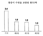
표준 SCS 치료법보다 본 발명에 개시된 치료법으로 더 큰 통증 경감을 수득하는 것에 더하여, 환자는 도 3-5C를 참조로 하기에 추가로 기술되는 다른 이점을 또한 경험하였다. 도 3은 환자가 조정 변화를 개시한 횟수/일을 도해하는 막대 그래프이다. 표준 SCS 치료법 (막대 301) 및 본 발명에 개시된 치료법 (막대 302)에 대해 결과가 도해된다. 환자-개시 조정 변화는 일반적으로 적용된 신호의 진폭에서의 변화였고, 도 1a를 참조로 상기에 기술된 바와 같이 외부 조정기 또는 리모트를 통해 환자에 의해 개시되었다. 표준 SCS 치료법을 받은 환자는 신호 전달 파라메터에 대한 변화를 평균 44회/일로 개시하였다. 개시된 변화는 환자가 위치, 활동 수준 및/또는 활동 유형을 변화시키고, 그 후 통증 경감에서의 감소 및/또는 불쾌하거나, 불편하거나, 통증이 있거나, 원치 않거나 예상하지 않은 감각을 치료 신호로부터 경험했을 때 전형적으로 유발되었다. 본 발명에 개시된 치료법을 받은 환자는 진료의의 요청시를 제외하고는 신호 전달 파라메터를 전혀 변화시키지 않았다. 특히, 환자가 통증이 있는 자극을 피하도록 신호 진폭을 변화시키지 않았다. 따라서, 도 3은 본 발명에 개시된 치료법이 도선 이동, 환자 위치, 활동 수준 및 활동 유형에 대해 표준 SCS 치료법보다 유의하게 덜 민감하다는 것을 가리킨다.In addition to achieving greater pain relief with the treatments disclosed herein than with standard SCS therapies, the patient has also experienced other advantages that are further described below with reference to Figures 3-5C. Figure 3 is a bar graph illustrating the number / day that a patient initiated an adjustment change. Results are illustrated for standard SCS therapies (rod 301) and for the treatment disclosed in the present invention (rod 302). The patient-initiated coordination change was typically a change in the amplitude of the applied signal and was initiated by the patient via an external regulator or remote as described above with reference to FIG. 1A. Patients receiving standard SCS therapy initiated a change in signaling parameters with an average of 44 beats / day. The disclosed changes can be made by a person who has experienced a change in position, activity level and / or type of activity and then a reduction in pain relief and / or unpleasant, uncomfortable, painful, . Patients receiving the treatment disclosed in the present invention did not change the signaling parameters at all except at the request of the clinic. In particular, the patient did not change the signal amplitude to avoid painful stimuli. Thus, FIG. 3 indicates that the treatment disclosed in the present invention is significantly less sensitive than standard SCS therapies for lead migration, patient location, activity level and activity type.
도 4는 본 발명에 개시된 치료법을 받은 환자에 대한 활동 점수를 도해하는 막대 그래프이다. 활동 점수는 환자가 착수할 수 있는 활동의 양에 대한 환자의 만족 수준을 일반적으로 가리키는 삶의 질 점수이다. 도 4에 지시된 바와 같이, 막대 401은 치료법을 시작하기 전에 점수가 1.9 (예를 들어, 불량 내지 보통)인 환자를 식별한다. 경시적으로 점수가 개선되어 (막대 402-404), 치료법 제2일 말기에 환자는 거의 3점 ("양호" 점수에 상응함)을 보고하였다. 더 긴 연구에서, 환자의 점수가 도 4에 제시된 결과를 넘어서 잘 개선될 수 있을 것으로 예상된다. 그러나, 도 4에 제시된 결과조차도 3일 기간에 걸쳐 본 발명에 개시된 치료법을 받은 환자에 대해 활동 점수에서의 53% 개선 (기저선과 비교)을 가리킨다. 일화적으로, 환자는 표준 SCS 치료법을 받았을 때보다 본 발명에 개시된 치료법을 받았을 때 더욱 활동적이었음을 또한 가리켰다. 일화 보고를 기초로, 표준 SCS 치료법을 받은 환자는 동일한 기간에 걸쳐 활동 점수에서의 단지 10 - 15%만의 개선을 경험할 것으로 예상된다. Figure 4 is a bar graph illustrating the activity score for a patient who received the treatment disclosed in the present invention. The activity score is a quality-of-life score that generally indicates the level of patient satisfaction with the amount of activity the patient can undertake. As indicated in FIG. 4, the
도 5a는 본 발명에 개시된 치료법을 받고, 서있기, 걷기, 오르기, 앉아 있기, 차 타기, 및 먹기의 6가지 활동을 수행한 환자에 대한 활동 점수에서의 변화를 도해하는 막대 그래프이다. 각각의 이러한 활동에 대해, 막대 군 (개별적인 군이 참조 번호 501, 502, 503 … 506으로 식별됨)은 경시적으로 환자의 활동 점수가 일반적으로 개선되었음을 가리킨다. 이러한 결과들은 활동에서의 개선이 광범위하였고, 특정 활동에 제한되지 않았음을 추가로 가리킨다. 추가로, 이러한 결과들은 먹기에 대한 30% 내지 서있기, 걷기 및 계단 오르기에 대한 80% - 90% 범위의 각각의 활동에서의 유의한 수준의 개선을 가리킨다. 일화적으로, 표준 SCS 치료를 받은 환자는 환자 활동에서의 단지 약 10% - 20%만의 개선을 경험할 것으로 예상된다. 또한 일화적으로, 표준 SCS 치료를 받을 때 등을 구부렸고, 똑바로 서지 못한 적어도 일부 환자에서 활동 수준에서의 개선이 직접적으로 관찰되었다. 대조적으로, 본 발명에 개시된 치료법을 받았을 때 이러한 환자들은 똑바로 설 수 있었고, 다른 정상적인 활동에 관여할 수 있었다.FIG. 5A is a bar graph illustrating the change in activity score for a patient who underwent the treatment disclosed in the present invention and performed six activities: standing, walking, climbing, sitting, kicking, and eating. For each such activity, the bar group (identified as
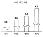
환자가 경험한 개선은 활동에서의 개선에 한정되지 않고, 수면이 포함되는 상대적인 무활동에 또한 확장된다. 예를 들어, 표준 SCS 치료법을 받은 환자는 엎드려 누워있을 때 특정 수준의 신호 전달 파라메터를 확립할 수 있다. 수면 동안 환자가 뒹굴 때, 환자가 깨도록 하는 표준 SCS 치료가 제공하는 통증 감소에서의 유의한 충분한 변화를 환자가 경험할 수 있다. 많은 경우에, SCS 신호가 감소시키도록 의도되는 통증에 더하여, SCS 신호 자체에 의해 생성되는 통증을 환자가 추가적으로 경험할 수 있다. 대조적으로, 본 발명에 개시된 기법으로, 이러한 바람직하지 않은 효과를 피할 수 있다. 도 5b 및 5c는 본 발명에 개시된 치료법을 받은 임상 환자에 대한 수면에 대한 평균 효과를 도해한다. 도 5b는 환자 교란에서의 감소를 도해하고, 도 5c는 수면 시간 수에서의 증가를 도해한다. 다른 실시양태에서, 환자가 통증이 감소되면서 다른 직무를 수행할 수 있을 수 있다. 예를 들어, 이식된 장치에 의해 제공되는 치료법 수준을 조절할 필요가 없으면서 환자가 운전할 수 있다. 따라서, 이같은 상황 및/또는 환자의 삶의 질을 개선시키는 기타 상황에서 환자가 본 발명에 개시된 치료법을 더욱 쉽게 사용할 수 있다.Improvements experienced by the patient are not limited to improvements in activity, but also extend to relative inactivity, including sleep. For example, patients who receive standard SCS therapy can establish certain levels of signaling parameters when lying down. Patients may experience significant significant changes in pain relief provided by standard SCS therapy, which allows the patient to awaken when the patient rolls over during sleep. In many cases, in addition to the pain that the SCS signal is intended to reduce, the patient may additionally experience the pain generated by the SCS signal itself. In contrast, with the technique disclosed in the present invention, this undesirable effect can be avoided. Figures 5b and 5c illustrate the average effect on sleep for a clinical patient receiving the treatment disclosed in the present invention. Figure 5b illustrates a reduction in patient disturbance, and Figure 5c illustrates an increase in sleep time number. In another embodiment, the patient may be able to perform other tasks with reduced pain. For example, the patient can drive without having to adjust the level of treatment provided by the implanted device. Thus, the patient can more readily use the therapies disclosed in the present invention in such situations and / or in other situations that improve the quality of life of the patient.
추가적인 환자 피드백(feedback)을 기초로, 표적 위치에서 본 발명에 개시된 치료법을 받은 (예를 들어, 의도된 도선 위치로부터 도선을 유의하게 이동시키지 않으면서 본 발명에 개시된 치료법을 받은) 테스트 환자 모두가 표준 SCS 치료법보다 본 발명에 개시된 치료법을 선호하였다. 또한, 환자가 받은 통증 경감 수준과 관계없이, 지각이상을 생성시키지 않으면서 환자의 통증을 감소시켰기 때문에 환자의 88%가 표준 SCS 치료법보다 본 발명에 개시된 치료법을 선호하였다. 이는 환자가 통증보다 지각이상을 선호할 수 있는 한편, 유의한 대다수는 통증 및 지각이상 둘 다보다 감각이 없는 것을 선호한다는 것을 가리킨다. 본 발명에 개시된 치료법을 통해 수득된 이러한 결과는 통증 경감을 일으키기 위해 지각이상 (즉, 차폐)에 의존하는 것으로 통상적으로 이해되는 표준 SCS 치료법으로 입수할 수 없다.On the basis of additional patient feedback, all of the test patients who received the therapy described herein (e.g., who received the treatment disclosed in the present invention without significantly shifting the lead from the intended lead position) Preferred the treatment described in the present invention over standard SCS therapies. In addition, 88% of patients preferred the treatment described in the present invention over standard SCS treatments because they reduced the patient's pain without generating a perineal abnormality regardless of the patient's level of pain relief. This indicates that the patient may prefer a perceptual abnormality over pain, while a significant majority prefer to have no sensation of both pain and perception abnormality. These results obtained through the treatment described in the present invention are not available with standard SCS therapies that are commonly understood to depend on crustal anomalies (i.e., shielding) to cause pain relief.
추가로, 일화 데이터는 본 발명에 개시된 치료법을 받은 환자가 표준 SCS으로 경험하는 것보다 더 적은 근육 포획을 경험하였음을 가리킨다. 특히, 환자가 연축, 경련, 및 근육 통증의 결여를 보고하였고, 표준 SCS를 받았을 때는 이들 중 일부 또는 모두를 경험하였다. 또한 환자는 수의근 작용의 방해를 보고하지 않았고, 대신 본 발명에 개시된 치료법에 의해 방해되지 않는 운동 직무를 수행할 수 있었음을 가리켰다. 추가로, 환자는 접촉 (예를 들어, 진동 감지), 온도 및 고유감각의 감각이 포함되는 다른 감각의 방해를 보고하지 않았다. 대부분의 경우에, 환자는 침해성 통증 감각의 방해를 보고하지 않았다. 그러나, 일부 경우에, 환자는 절개 통증 (신호 전달 도선을 이식하기 위해 사용된 절개와 관련됨)의 부재 또는 만성 말초 통증 (관절염과 관련됨)의 부재를 보고하였다. 따라서, 특정 실시양태에서, 급성 말초 통증 및/또는 만성 말초 통증이 포함되는 침해성 통증을 다루도록 본 발명에 개시된 기법의 측면이 사용될 수 있다. 예를 들어, 적어도 일부 경우에, 낮은 침해성 통증 내지 중등도의 침해성 통증이 있는 환자에게 상기 치료법의 결과로서 경감이 수여되었다. 더욱 중증인/만성 침해성 통증이 있는 환자는 전형적으로 본 발명의 치료법 기법에 충분히 응답성이지 않았다. 이러한 결과는, 하기에 더욱 상세하게 논의되는 바와 같이, 환자가 경험하는 통증의 유형을 구별하기 위한 진단 환경에서 사용될 수 있다.In addition, anecdotal data indicate that patients undergoing the treatments disclosed herein experienced less muscle trauma than experienced with standard SCS. In particular, patients reported spasticity, seizures, and lack of muscle pain and experienced some or all of these when they received standard SCS. The patient also did not report disruption of the musculoskeletal activity and instead indicated that he was able to perform athletic tasks not interrupted by the treatment described in the present invention. In addition, the patient did not report disturbances of other senses, including touch (e.g., vibration detection), temperature, and sense of inherent sensation. In most cases, the patient did not report any disruption of the intractable pain sensation. In some cases, however, the patient reported absence of incisional pain (associated with the incision used to implant the signaling conductor) or chronic peripheral pain (associated with arthritis). Thus, in certain embodiments, aspects of the techniques disclosed herein may be used to address invasive pain, including acute peripheral pain and / or chronic peripheral pain. For example, at least in some cases relief has been granted to patients with low to moderate intractable pain as a result of the treatment. Patients with more severe / chronic invasive pain were typically not sufficiently responsive to the treatment techniques of the present invention. These results can be used in a diagnostic environment to distinguish the type of pain experienced by a patient, as discussed in more detail below.
도 6a는 본 발명에 개시된 치료법을 제공한 도선 상의 활성 접점의 위치 (척추 레벨로 지시됨)의 함수로서 성공적인 치료 결과의 수를 가리키는 막대 그래프이다. 일부 경우에, 조정이 하나를 초과하는 척추 위치에서 제공되었을 때 환자가 성공적인 결과를 수득하였다. 도 6a에 지시된 바와 같이, 척추체 T9 내지 T12의 큰 축 범위 (척추를 따라 상위-하위 방향으로 측정됨)에 걸쳐 성공적인 결과가 수득되었다. 선호되는 표적 위치 (예를 들어, T10 주변)가 있을 수 있는 한편, 성공적인 결과를 여전히 일으키면서 도선이 광범위한 위치에 놓일 수 있음을 가리킨다는 점에서 이는 놀라운 결과이다. 특히, 이웃하는 척추체들은 전형적으로 서로 약 32 ㎜ (특정 환자의 해부 구조에 좌우됨)만큼 간격을 두고, 따라서 성공적인 결과가 광범위한 4개의 척추체 (약 128 ㎜) 및 더 좁은 범위의 1개 내지 2개의 척추체 (약 32-64 ㎜)에 걸쳐 수득되었다. 대조적으로, 표준 SCS 데이터는 도선 위치에서의 1 ㎜만큼 적은 이동으로 치료법이 효과적에서 비-효과적으로 변화될 수 있음을 일반적으로 가리켰다. 하기에 더욱 상세하게 논의되는 바와 같이, 본 발명에 개시된 치료법과 관련된 유연성 및 다능성은 환자 및 진료 둘 다에게 유의한 이점을 일으킬 수 있다.6A is a bar graph depicting the number of successful treatment results as a function of the location of the active contacts on the leads (indicated by the vertebral level) providing the treatment disclosed in the present invention. In some cases, when the adjustment was provided in more than one spinal position, the patient obtained a successful result. As shown in Fig. 6A, successful results have been obtained over a large axial range of vertebral bodies T9 to T12 (measured in the upper-lower direction along the vertebrae). This is an incredible result in that while there may be a preferred target location (for example, around T10), the wire may still be in a wider position while still causing a successful result. In particular, neighboring vertebrae are typically spaced about 32 mm apart (depending on the anatomy of the particular patient), so that successful results include four broad vertebrae (about 128 mm) and a narrower range of one to two Vertebral bodies (about 32-64 mm). In contrast, standard SCS data generally indicated that the treatment could be changed from effective to non-effective with as little as 1 mm of travel in the lead position. As discussed in more detail below, the flexibility and versatility associated with the therapies disclosed herein can bring significant benefits to both patients and care.
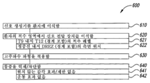
도 6b 및 6c는 본 개시내용의 특정 실시양태에 따라 환자를 치료하는 방법을 도해하는 순서도이다. 제조사 또는 기타 적절한 업체가 이러한 방법 및 본원에 개시된 기타 방법을 실행하기 위해 진료의에게 설명서를 제공할 수 있다. 또한 제조사는 개시된 시스템의 장치를 이러한 방법들 중 적어도 일부를 수행하도록 프로그래밍할 수 있다. 도 6b는 신호 생성기를 환자에 이식하는 것 (블록 610)을 포함하는 방법 600을 도해한다. 신호 생성기는 환자의 허리 또는 기타 적절한 위치에 이식될 수 있다. 방법 600은 환자의 척수 영역에서 신호 전달 장치 (예를 들어, 도선, 패들 또는 기타 적절한 장치)를 이식하는 것 (블록 620)을 추가로 포함한다. 차례로 방법의 이러한 부분은 약 T9 내지 약 T12 (예를 들어, 약 T9-T12 (경계 포함)) 범위의 척추 레벨에서 (블록 621), 및 척수 정중선 내지 DREZ (경계 포함) 범위의 측면 위치에서 (블록 622), 장치 (예를 들어, 장치의 활성 접점)를 이식하는 것을 포함할 수 있다. 블록 630에서, 방법은 신호 생성기 및 신호 전달 장치를 통해 고주파수 파형을 적용하는 것을 포함한다. 특정 예에서, 신호 (또는 적어도 신호의 일부분)의 주파수는 약 1.5 kHz 내지 약 100 kHz, 또는 약 1.5 kHz 내지 약 50 kHz, 또는 약 3 kHz 내지 약 20 kHz, 또는 약 3 kHz 내지 약 15 kHz, 또는 약 5 kHz 내지 약 15 kHz, 또는 약 3 kHz 내지 약 10 kHz일 수 있다. 방법 600은 환자의 통증, 예를 들어, 만성 허리 통증을 차단하거나, 저해하거나, 억제하거나 또는 다른 방식으로 감소시키는 것 (블록 640)을 추가로 포함한다. 차례로 방법의 이러한 부분은 원치 않는 감각 효과 및/또는 제한 없이 (블록 641), 및/또는 운동 효과 없이 (블록 642), 통증을 감소시키는 것을 포함할 수 있다. 예를 들어, 블록 641은 다른 감각의 환자 인지를 감소시키지 않으면서, 및/또는 추가적인 통증을 유발하지 않으면서 통증을 감소시키거나 제거하는 것을 포함할 수 있다. 블록 642는 근육 작용을 유발하지 않으면서 및/또는 운동 신호 전송을 방해하지 않으면서 통증을 감소시키거나 제거하는 것을 포함할 수 있다.Figures 6B and 6C are flowcharts illustrating a method of treating a patient according to certain embodiments of the present disclosure. A manufacturer or other appropriate vendor may provide instructions to the practitioner to perform these methods and other methods described herein. The manufacturer may also program the apparatus of the disclosed system to perform at least some of these methods. 6B illustrates a
도 6c는 도 6b를 참조로 상기 기술된 것들에 더한 특색들을 포함하는 방법 601을 도해한다. 예를 들어, 고주파수 파형을 적용하는 프로세스 (블록 630)가 원치 않는 부작용, 예컨대 바람직하지 않은 감각 및/또는 운동 방해를 생성시키지 않으면서 넓은 진폭 범위 (예를 들어, 한 실시양태에서의 1 mA 미만 내지 약 8 mA 이하, 및 다른 실시양태에서의 각각 약 6 mA 및 약 5 mA 이하)에 걸쳐 그렇게 하는 것 (블록 631)을 포함할 수 있다. 또 다른 실시양태에서, 고주파수 파형을 적용하는 프로세스가 고정된 진폭에서 파형을 적용하는 것 (블록 632)을 포함할 수 있다. 하기에 추가로 기술되는 바와 같이, 이러한 측면 각각이 환자 및/또는 진료의 이점을 제공할 수 있다.Figure 6C illustrates a
환자 통증을 차단하거나, 억제하거나 또는 다른 방식으로 감소시키는 프로세스 (블록 640)는 지각이상을 생성시키지 않으면서 (블록 643), 또는 신중하게 생성된 지각이상과 함께 (블록 644), 그렇게 하는 것을 포함할 수 있다. 상기 언급된 바와 같이, 임상 결과는 대부분의 환자가 지각이상의 존재보다 지각이상의 부재를 선호하는 것을 가리키는데, 예를 들어, 이는 환자가 위치를 변화시키고/시키거나 신호 진폭을 조절할 때 지각이상의 감각이 불편하거나 통증이 있는 감각으로 변화할 수 있기 때문이다. 그러나, 일부 경우에는, 환자가 지각이상의 감각을 선호할 수 있고 (예를 들어, 앞서 SCS를 받은 환자), 따라서 이를 받을 선택권을 지닐 수 있다. 지각이상을 유도하는 조정과 지각이상을 유도하지 않는 조정의 조합을 포함하는 방법의 상세사항이 앞서 본원에 참고로 포함된 미국 가출원 번호 61/171,790에 포함된다. 다른 경우에, 부위 선택을 위해 진료의가 지각이상을 사용할 수 있다 (예를 들어, 활성 전극이 놓이는 위치를 결정하기 위해). 상기에 더하여, 환자 통증을 감소시키는 것은 표준 SCS가 일반적으로 매우 민감한 환자 속성에 대해 비교적 무감응성이면서 그렇게 하는 것 (블록 645)을 포함할 수 있다. 이러한 속성은 환자 이동 (블록 646) 및/또는 환자 위치 (블록 647)를 포함할 수 있다.The process of blocking, suppressing or otherwise reducing patient pain (block 640) includes doing so without creating a tardy anomaly (block 643), or with a carefully generated tardy anomaly (block 644) can do. As noted above, clinical outcomes indicate that most patients prefer a more than perceptual absence to a more than perceptual presence, for example, when a patient changes position and / or controls signal amplitude, It can change with uncomfortable or painful sensations. In some cases, however, the patient may prefer a sensation above the perception (e. G., A patient who has received a previous SCS) and therefore may have the option of receiving it. Details of how to include a combination of an adjustment to induce a tardive anomaly and an adjustment to not induce a tardive anomaly are included in U.S. Provisional Application No. 61 / 171,790, the disclosure of which is incorporated herein by reference in its entirety. In other cases, a threshold of medical care may be used for site selection (e.g., to determine where the active electrode is located). In addition to reducing the patient pain, the standard SCS may be relatively insensitive to very sensitive patient attributes and may include doing so (block 645). These attributes may include patient movement (block 646) and / or patient location (block 647).
2.2. 후속 연구 2.2. Follow-up study
본 출원의 양수인인 네브로 코포레이션은 상기 기술된 치료법의 특정 파라메터 및 결과를 평가하기 위해 후속 연구를 수행하였다. 후속 연구에서, 이식된 도선 및 시뮬레이터(simulator)를 환자에게 제공하였고, 수개월의 기간에 걸쳐 치료법을 제공하였다. 이러한 연구는 각각의 환자에 대한 통상적인 SCS 기법과의 직접적인 비교를 포함하지 않았지만, 일부 환자는 본 발명의 기술에 따른 조정을 받기 전에 통상적인 SCS 치료법을 받았다. 선택된 결과가 하기에 추가로 기술된다. NebrCorporation, the assignee of the present application, has conducted subsequent studies to evaluate the specific parameters and results of the treatments described above. In a follow-up study, implanted leads and a simulator were provided to the patient and treatment was provided over a period of months. Although this study did not include direct comparisons with conventional SCS techniques for each patient, some patients received conventional SCS therapy before receiving adjustments according to the techniques of the present invention. Selected results are further described below.
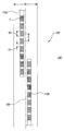
도 7a는 후속 연구 동안 사용된 전형적인 도선 배치의 개략도이다. 이러한 연구에서, 2개의 도선 111 (제1 도선 111a 및 제2 도선 111b로 제시됨)이 일반적으로 끝과 끝이 이어지도록 놓여서, 환자의 등뼈의 여러 척추 레벨에 걸쳐 연장되는 조정 능력을 제공하였다. 도선 위치에서의 가능한 이동을 고려하도록 도선 111a, 111b가 약간 중첩되도록 놓였다. 치료법 과정 동안, 2개의 도선 111a, 111b의 접점 C가 한 번에 1개의 도선 상에서 활성화되었다. 달리 말하면, 오직 1개의 도선 111의 접점 C가 임의의 한 시점에 활성이었고, 다른 도선 111 상에 위치한 접점 C 사이에는 신호가 지시되지 않았다. 2개의 도선이 임상 연구 동안 사용된 한편, 일반적인 용도에서는, 단일 도선이 적합한 척추 레벨에 놓일 수 있는 것으로 예상된다. 도 9를 참조로 하기에 더욱 상세하게 기술되는 바와 같이, 본원에 기술된 것과 동일하거나 유사한 효과를 달성하도록 도선에 더 넓은 간격의 접점들이 있을 수 있다.Figure 7a is a schematic diagram of a typical wire arrangement used during subsequent studies. In this study, two leads 111 (shown as first lead 111a and second lead 111b) were generally placed end to end to provide adjustment capability extending over several vertebral levels of the patient's spine. The conductors 111a and 111b are placed so as to slightly overlap so as to allow for possible movement at the lead position. During the treatment process, contact C of the two leads 111a, 111b was activated on one lead at a time. In other words, the contact C of only one
각각의 도선 111a, 111b의 접점 C는 폭 W2가 약 3 ㎜이고, 약 1 ㎜의 간격 D1만큼 서로 분리된다. 따라서, 이웃하는 접점 C들 사이의 중심-대-중심 간격 S는 약 4 ㎜이다. 도선 111a, 111b가 환자의 척추 정중선 189에 또는 이에 가깝게 놓였다. 전형적으로, 하나의 도선이 정중선 189의 한쪽에 놓였고, 나머지 도선이 환자의 정중선 189의 다른 쪽에 놓였다. 연구 과정 동안, 여러 유의한 효과가 관찰되었다. 예를 들어, 치료 효능에 유의하게 영향을 미치지 않으면서, 도선 111a, 111b가 전체 폭이 정중선 189로부터 ± 3-5 ㎜인 상대적으로 넓은 창 W1 (예를 들어, 6-10 ㎜의 전체 폭) 내의 다양한 위치 중 임의의 위치에 놓일 수 있었다. 또한, 양측성 통증 (예를 들어, 정중선 189의 양쪽에서의 통증)이 있는 환자가 도선 110a, 110b의 측면 위치와 관계없이 양측성 경감을 보고하였다. 예를 들어, 정중선 189의 한쪽에서 창 W1 내에 도선이 위치하는 환자가 정중선 189의 반대쪽에서 통증 경감을 보고하였다. 이는 엄격하게 정중선인 도선 위치로부터의 임의의 일탈에 대해 양측성 경감 (약간이라도 수득되는 경우)이 일반적으로 매우 민감한 통상적인 SCS 치료법과 다르다. 추가로, 이웃하는 활성 접점들 사이의 거리가 표준 SCS에 대해 전형적인 것보다 유의하게 더 컸다. 이웃하는 활성 접점들의 중심-대-중심 간격이 예를 들어 20 ㎜이고 가장자리-대-가장자리 간격이 예를 들어 17 ㎜이도록 진료의가 여러 연속적인 접점들을 "생략" (예를 들어, 비활성화)할 수 있었다. 또한, 환자가 활성 접점의 축 위치에 대해 비교적 무감응성이었다. 예를 들어, 진료의가 2개의 척추체까지 걸쳐질 것으로 예상되는 광범위한 접점 간격 (예를 들어, 약 64 ㎜)에 걸쳐 동일하거나 일반적으로 동일한 수준의 통증 경감을 확립할 수 있었다. 추가적으로, 본원과 동시에 출원되고 참고로 본원에 포함된, 계류 중인 미국 출원 12/___________ (대리인 문서 번호 66245.8024US)에 더욱 상세히 기술된 바와 같이, 소정의 접점이 캐소드 또는 애노드로 식별되는지와 관계없이 진료의가 유사한 치료 효과를 수득하였다.The contacts C of the conductors 111a and 111b have a width W2 of about 3 mm and are separated from each other by an interval D1 of about 1 mm. Thus, the center-to-center spacing S between neighboring contacts C is about 4 mm. The leads 111a, 111b were placed at or near the
후속 연구에서의 대부분의 환자에 대해, T9-T10 척추 위치에서 도선이 이식되었다. 이러한 환자들은 치료법을 받기 전에 1차적으로 허리 통증을 전형적으로 경험하였지만, 일부는 다리 통증을 또한 경험하였다. 후속 연구 및 초기 연구 동안 수득된 결과를 기초로, 허리 통증을 다루기 위한 전체적인 척추 위치 범위는 약 T9 내지 약 T12인 것으로 예상된다. 이러한 범위 내에서, T12 또는 T11-T12에서의 조정이 허리 및 다리 통증 둘 다가 있는 환자를 더욱 효과적으로 치료할 수 있는 것으로 추가로 예상된다. 그러나, 일부 경우에, 더 높은 척추 위치 (예를 들어, T9-T10)에서 환자가 더 큰 다리 통증 경감을 경험하였고, 추가적인 특정 경우에, T9에서의 조정이 T10에서의 조정보다 더 많은 다리 통증 경감을 일으켰다. 따라서, 상기 기술된 일반적인 범위 내에서, 특정 환자는 상응하는 선호되는 척추 위치를 생성시키는 생리학적 특징 또는 기타 요인이 있을 수 있다.For most of the patients in the follow-up study, the wires were implanted at the T9-T10 spine position. These patients typically experienced back pain primarily before receiving treatment, but some also experienced leg pain. Based on the results obtained during subsequent studies and early studies, the overall spinal location range for dealing with back pain is expected to be from about T9 to about T12. Within this range, it is further expected that adjustments in T12 or T11-T12 can more effectively treat patients with both back and leg pain. However, in some cases, the patient experienced greater leg pain relief at a higher spinal position (e.g., T9-T10), and in additional specific cases, adjustment at T9 resulted in more leg pain It was a relief. Thus, within the general scope described above, certain patients may have physiological characteristics or other factors that produce a corresponding preferred spinal position.
후속 연구에서의 치료를 받는 환자에게 약 10 kHz의 주파수의 네모파(square-wave) 신호가 제공되었다. 약 2 mA의 초기 전류 진폭 (2상성)으로, 100% 듀티 사이클의 조정이 환자에게 제공되었다. 환자 및 진료의는 신호 진폭을, 전형적으로 약 5 mA까지, 조절할 수 있었다. 임의의 상기 수준에서, 신호 펄스가 역치상(suprathreshold)일 것으로 예상되고, 이는 표적 신경 집단에서의 임의의 내재성 신경 활성과 관계없이 펄스가 표적 신경 집단에서 활동 전위를 유발할 수 있음을 의미한다.A patient receiving treatment in a follow-up study was provided with a square-wave signal at a frequency of about 10 kHz. With an initial current amplitude of about 2 mA (biphasic), a 100% duty cycle adjustment was provided to the patient. Patients and caregivers could adjust the signal amplitude, typically up to about 5 mA. At any of these levels, the signal pulse is expected to be a suprathreshold, meaning that the pulse can induce an action potential in the target neural population, regardless of any endogenous neuronal activity in the target neuron population.
후속 연구의 환자를 조정 시스템 100이 이식 및 활성화된 후 주기적으로 평가하였다. 30일 동안 치료를 받은 후 이러한 환자들이 보고한 VAS 점수는 평균 약 1.0이었고, 이는 도 2와 관련하여 상기 논의된 경향이 얼마간의 기간 동안 계속되었음을 가리킨다. 이러한 환자들 중 적어도 일부는 약 2.25 수준까지의 VAS 점수에서의 증가를 보고하였다. 환자의 증가된 활동 수준으로부터 이러한 증가가 초래된 것으로 예상된다. 따라서, 이러한 증가가 치료 효능에서의 감소를 가리키는 것으로 여겨지지 않고, 그보다는, 환자가 그렇지 않은 경우에는 관여하지 않을 활동에 관여하도록 하는 효과적인 치료법을 가리킨다.Patients from follow-up studies were periodically evaluated after
도 7b는 다양한 활동에 관여하고 후속 연구 프로토콜에 따른 조정을 받은 환자에 대한 전체적인 오스웨스트리 점수를 도해한다. 100점은 완전히 장애인 상태에 상응하고, 0점은 장애 없음에 상응한다. 이러한 점수는, 예를 들어, 초기 연구로부터 수득된 결과와 일치하고 실제로 이러한 결과에 비해 개선된, 경시적인 일반적인 개선을 가리킨다. 또한, 여러 환자들이 상기 실시양태에 따른 치료법을 받은 후 더 이상 지팡이 또는 휠체어를 필요로 하거나 사용하지 않는 것을 보고하였다.Figure 7b illustrates the overall Oswestry score for patients involved in various activities and adjusted for follow-up protocol. A score of 100 corresponds to a completely disabled condition, and a score of zero corresponds to no obstacle. These scores indicate, for example, a general improvement over time, consistent with the results obtained from the initial study and actually improved over these results. In addition, several patients reported that they no longer need or use a cane or wheelchair after receiving the treatment according to the embodiment.
후속 연구로부터의 결과는 전류 진폭에서의 변화에 대해 치료의 치료 유효성이 비교적 무감응성인 것을 확증한다. 특히, 환자에게 약 2.0 mA 내지 약 3.5 mA 수준에서의 조정이 전형적으로 제공되었다. 대부분의 경우에, 적용된 신호의 진폭을 변화시켰을 때 환자는 통증 감소에서의 유의한 변화를 보고하지 않았다. 여러 경우에, 환자는 바람직하지 않은 부작용을 보고하기 전까지 전류 진폭을 약 5 mA의 수준까지 증가시킬 수 있었다. 또한, 부작용은 갑작스러운 방식보다는 점진적인 방식으로 발생하기 시작하였다. 일부 환자로부터의 일화적 피드백은 임의의 바람직하지 않은 부작용의 발현과 관계없이, 높은 진폭 (예를 들어, 5 mA 초과)에서 치료 효능이 저하되기 시작하였음을 가리켰다. 2 mA 미만의 전류 진폭에서 환자가 효과적인 치료법을 받을 수 있는 것으로 추가로 예상된다. 이러한 예상은 듀티 사이클을 (예를 들어, 70%로) 감소시키는 것이 효능을 감소시키지 않았음을 가리키는 데이터를 적어도 부분적으로 기초로 한다.The results from subsequent studies confirm that the therapeutic efficacy of the treatment is relatively insensitive to changes in current amplitude. In particular, adjustments at the level of about 2.0 mA to about 3.5 mA have typically been provided to the patient. In most cases, the patient did not report any significant changes in pain reduction when the amplitude of the applied signal was changed. In many cases, the patient could increase the current amplitude to a level of about 5 mA before reporting undesirable side effects. Side effects also began to occur in a gradual way rather than in an abrupt manner. Anecdotal feedback from some patients indicated that therapeutic efficacy began to degrade at high amplitudes (eg, greater than 5 mA), regardless of the occurrence of any undesirable side effects. It is further expected that patients will be able to receive effective therapies at a current amplitude of less than 2 mA. This prediction is based, at least in part, on data indicating that decreasing the duty cycle (e. G., 70%) did not reduce efficacy.
후속 연구의 결과는 일단 시스템이 이식 및 활성화되면, 대부분의 환자 (예를 들어, 환자의 약 80%)가 신호 전달 파라메터 (예를 들어, 활성 접점의 수 및/또는 위치, 및/또는 전류 진폭)의 임의의 양상을 변화시키지 않으면서 적어도 만족스러운 통증 감소를 경험하였음을 또한 가리켰다. 소규모의 환자 (예를 들어, 약 20%)는 특정 활동에 관여할 때 증가된 전류 진폭으로부터 이익을 얻었고/얻었거나 수면 시 더 낮은 전류 진폭으로부터 이익을 얻었다. 이러한 환자들에 대해, 활동에 관여하면서 신호 진폭을 증가시키는 것은 더 큰 정도의 통증 경감을 일으켰고, 밤에 진폭을 감소시키는 것은 과잉자극의 경향을 감소시키는 한편 동시에 전력을 절약하였다. 대표적인 예에서, 환자들은 2가지의 이같은 프로그램으로부터 선택하였다: 비교적 높은 전류 진폭 (예를 들어, 약 1 mA 내지 약 6 mA)의 신호를 제공하는 "강" 프로그램, 및 더 낮은 전류 진폭 (예를 들어, 약 0.1 mA 내지 약 3 mA)의 신호를 제공하는 "약" 프로그램.The results of subsequent studies indicate that once the system is implanted and activated, most patients (e. G., About 80% of the patients) have signaling parameters (e.g., number and / or location of active contacts and / ≪ / RTI > at least satisfactory pain relief without altering any aspect of pain relief. Smaller patients (eg, about 20%) benefited from increased current amplitudes when engaged in certain activities and / or benefited from lower current amplitudes at sleep. For these patients, increasing signal amplitude while engaging in activity caused a greater degree of pain relief, and reducing the amplitude at night reduced the tendency to overstimulation while simultaneously saving power. In a representative example, patients selected from two such programs: a "strong" program that provides a signal with a relatively high current amplitude (e.g., about 1 mA to about 6 mA) &Quot; about "about 0.1 mA to about 3 mA).
후속 연구 동안의 또 다른 관찰된 효과는 본 발명의 기술에 따른 조정을 받기 전에 통증을 다루기 위해 환자에게 제공되었던 아편유사제 및/또는 기타 통증 의약의 섭취를 환자가 자발적으로 감소시킨 것이었다. 환자의 자발적인 약물 섭취 감소는 약물에 대한 필요성 감소의 직접적인 결과인 것으로 예상되고, 차례로 이는 본 발명의 기술에 따라 제공된 조정의 직접적인 결과이다. 그러나, 아편유사제의 중독성 성질로 인해, 환자가 용이하게 아편유사제의 사용을 자발적으로 포기하는 것은 놀라웠다. 그러므로, 적어도 일부 환자에 대해, 본 발명의 기술이, 통증을 감소시키는 것에 더하여, 이러한 약물들에 대한 화학물질 의존성을 감소시키도록 작용한 것으로 또한 예상된다. 따라서, 적어도 일부 실시양태에서, 본 개시내용에 따른 치료 기법이, 환자가 또한 허리 통증이 있고/있거나 허리 통증에 대해 치료되는지 여부와 관계없이, 환자의 화학물질 의존성을 감소시키거나 제거하는데 사용될 수 있는 것으로 추가로 예상된다.Another observed effect during subsequent studies was the patient's voluntary reduction in the intake of opioids and / or other pain medications that were provided to the patient to manage pain prior to adjustment according to the technique of the present invention. Decreased spontaneous drug intake in a patient is expected to be a direct result of a reduction in the need for the drug, which in turn is a direct result of the adjustments provided in accordance with the techniques of the present invention. However, due to the addictive nature of the opioids, it was surprising that the patient voluntarily abandoned the use of opioids. Therefore, for at least some patients, it is also contemplated that the techniques of the present invention, in addition to reducing pain, also serve to reduce the chemical dependency on these drugs. Thus, in at least some embodiments, the treatment technique according to this disclosure may be used to reduce or eliminate a patient ' s chemical dependency, regardless of whether the patient is also having back pain and / or being treated for back pain It is expected that there is more.
후속 연구에 참가하는 환자는 전형적으로 신경병증성 통증, 침해성 통증, 또는 신경병증성 통증과 침해성 통증의 조합을 경험하였다. 신경병증성 통증은 통증을 보고하기 위한 신경 메커니즘에서의 기능이상으로부터 초래되는 통증을 일반적으로 지칭하고, 이는 외부 신경 유발 없이 통증의 감각을 일으킬 수 있다. 침해성 통증은 특정한 기계적 또는 기타 신체적 효과 (예를 들어, 추간판 탈출, 근육 손상, 또는 골 손상)에 의해 유발될 때 환자가 적합하게 느끼는 통증을 일반적으로 지칭한다. 일반적으로, 신경병증성 통증은 일관적이고, 침해성 통증은, 예를 들어, 환자 위치 또는 활동에 따라, 변동된다. 적어도 일부 실시양태에서, 본 발명의 기술에 따른 치료는 침해성 통증보다 신경병증성 통증을 더욱 효과적으로 다루는 것으로 보인다. 예를 들어, 치료에 참가하기 전에 낮은 수준의 통증 변동 (신경병증성 통증을 우세하게 가리킴)을 보고한 환자가 통증이 유의하게 변동된 환자보다 치료 동안 통증 경감이 더 컸다. 2개의 특정 경우에, 치료법이 효과적인 것으로 증명되지 않았고, 이는 환자의 등 해부구조의 기계적인 문제점으로부터 초래된 것으로 여겨지며, 이에 의해 환자는 본 발명의 치료법보다는 수술에 대해 더욱 적합한 후보인 것으로 확인되었다. 따라서, 신경병증성 통증 및 (적어도 일부 경우에) 침해성 통증을 다루는 것에 더하여, 본 발명의 기술에 따른 기법은 신경병증성 통증보다는 침해성 통증을 주로 앓고 있는 환자를 확인하는 스크리닝 도구로서 또한 작용할 수 있다. 예를 들어, 진료의는 본 발명의 기술에 따른 신호를 수신할 때의 통증 감소의 존재 및/또는 양 (변동의 양 포함)에 상응하는 환자로부터의 피드백에 적어도 부분적으로 의존하여 이같은 확인을 할 수 있다. 이러한 진단 기법을 사용하는 것의 결과로서, 이러한 환자들은 침해성 통증을 직접적으로 다룰 수 있는 수술 절차 또는 기타 절차에 지시될 수 있다. 특히, 환자가 본 발명의 기술에 따른 신호를 수신할 수 있고, 응답이 없으면, 이러한 환자는 외과 수술에 대한 적절한 후보일 수 있다. 물론, 응답이 있으면, 환자가 치료법으로서 본 발명의 기술에 따른 신호를 계속 수신할 수 있다.Patients in subsequent studies have typically experienced a combination of neuropathic pain, invasive pain, or neuropathic pain and invasive pain. Neuropathic pain generally refers to the pain resulting from dysfunctions in the neural mechanisms for reporting pain, which can cause a sense of pain without external nerve induction. Inflammatory pain generally refers to pain that the patient feels appropriate when caused by a particular mechanical or other physical effect (e.g., an herniated disc, muscle damage, or bone damage). In general, neuropathic pain is consistent, and distracting pain varies, for example, with patient location or activity. In at least some embodiments, treatment according to the techniques of the present invention appears to treat neuropathic pain more effectively than invasive pain. For example, patients who reported a low level of pain variation (predominantly neuropathic pain) before participating in therapy had greater pain relief during treatment than those with significantly changed pain. In two particular cases, the treatment was not proven to be effective, and it is believed to be caused by a mechanical problem of the patient's back anatomy, thereby confirming that the patient is a more suitable candidate for surgery than the treatment of the present invention. Thus, in addition to dealing with neuropathic pain and (at least in some cases) invasive pain, techniques in accordance with the teachings of the present invention may also serve as screening tools to identify patients with predominantly invasive pain rather than neuropathic pain . For example, the practitioner may make such confirmation, at least in part, upon feedback from the patient corresponding to the presence and / or amount (including the amount of variation) of pain reduction when receiving a signal in accordance with the techniques of the present invention . As a result of using these diagnostic techniques, these patients may be instructed in surgical procedures or other procedures that can directly address the invasive pain. In particular, if the patient is able to receive a signal in accordance with the teachings of the present invention and there is no response, such patient may be a suitable candidate for surgery. Of course, if there is a response, the patient can continue to receive the signal according to the technique of the present invention as a therapy.
3.0 작용 메커니즘 3.0 Mechanism of action
도 8은 본 발명의 기술의 실시양태에 따라 제공되는 치료법에 대한 가능한 작용 메커니즘과 함께, 표준 SCS 치료에 대한 예상 작용 메커니즘을 도해하는 개략도이다 (문헌 [Linderoth and Foreman, "Mechanisms of Spinal Cord Stimulation in Painful Syndromes: Role of Animal Models", Pain Medicine, Vol. 51, 2006]을 기초로 함). 말초 신경이 손상된 경우, Aδ 및 C 통각수용기가 척수 후각의 2차 뉴런에게 증가된 수준의 흥분성 전송물질을 제공하는 것으로 여겨진다. 화살표 701로 표시되는 표준 SCS 치료법은 2가지 효과가 있는 것으로 예상된다. 1가지 효과는 척주를 따라 환자의 뇌로 전송되고 지각이상으로 인지되는 정방향 효과이다. 다른 효과는 개재뉴런 풀(pool)을 흥분시키는 역방향 효과이고, 이는 차례로 2차 뉴런으로의 입력을 억제한다.Figure 8 is a schematic diagram illustrating the anticipatory action mechanism for standard SCS therapy, along with possible mechanisms of action for therapies provided in accordance with embodiments of the techniques of the present invention (Linderoth and Foreman, "Mechanisms of Spinal Cord Stimulation in &Quot; Painful Syndromes: Role of Animal Models ", Pain Medicine, Vol 51, 2006). When peripheral nerves are damaged, it is believed that Aδ and C nociceptors provide an increased level of excitatory transmitters to secondary neurons in the spinal cord olfactory. The standard SCS treatment indicated by
본 발명에 개시된 치료법에 대한 한가지 가능한 작용 메커니즘이 화살표 710으로 표시되고, 후근 수준에서 불완전한 전도 차단 (예를 들어, 구심성 및/또는 원심성 신호 전송의 불완전한 차단)을 일으키는 것을 포함한다. 이러한 차단은, 후근에 더하여 또는 이를 대신하여, 척주, 후각, 및/또는 후근 진입부에서 발생할 수 있다. 임의의 이러한 경우에, 전도 차단은 더 작은 Aδ 및/또는 C 섬유에 대해 선택적이고/이거나 이에 우선적으로 영향을 미치고, 2차 뉴런에 대한 흥분 입력에서의 감소를 일으켜 척추 시상로를 따라 공급되는 통증 신호에서의 감소를 일으키는 것으로 예상된다.One possible mechanism of action for the treatment disclosed in this invention is indicated by
또 다른 가능한 작용 메커니즘 (도 8에서 화살표 720으로 표시됨)은 개재뉴런 풀을 더욱 깊게 활성화하고 따라서 2차 뉴런 내로의 입력의 억제를 증가시키는 것을 포함한다. 실제로, 이는 만성 통증과 관련된 신호의 효과가 환자에 대한 효과가 있기 전에 2차 뉴런을 잠재적으로 탈민감화시키고 이를 정상 상태에 더 가깝게 전환시킬 수 있다.Another possible action mechanism (indicated by
또 다른 가능한 작용 메커니즘은 만성 통증을 앓고 있는 환자에서의 뉴런의 민감도와 관련된다. 이같은 환자에서, 통증-전송 뉴런이 만성 통증을 경험하지 않는 사람들에서의 동일한 뉴런과 비교하여 상이한 과민성 상태에 있어, "일촉즉발(hair trigger)" 상태이고 만성 통증을 경험하지 않는 사람들에서의 세포보다 더 빈번하게, 그리고 더 낮은 자극 역치로 상이한 패턴으로 발화되는 고도로 민감화된 세포를 초래할 수 있는 것으로 여겨진다. 그 결과로서, 뇌가 유의하게 증가된 용량의 활동 전위를 유의하게 변경된 전송 패턴으로 수신한다. 따라서, 본 발명에 개시된 치료법이 작동될 수 있는 가능한 작용 메커니즘은 만성 통증 환자의 신경 세포의 "기저선"을 비-만성 통증 환자의 정상 기저선 및 발화 빈도를 향해 복원 또는 이동시킴으로써 이러한 과민성을 감소시키는 것에 의한 것이다. 차례로 이러한 효과는 다른 신경 전송 (예를 들어, 접촉, 열 등)에 영향을 미치지 않으면서 이러한 환자 집단에서의 통증의 감각을 감소시킬 수 있다.Another possible mechanism of action is related to the sensitivity of neurons in patients suffering from chronic pain. In these patients, the pain-transmitting neurons are in a different state of hypersensitivity compared to the same neurons in those who do not experience chronic pain, and are more "hair triggered" It is believed that this can result in highly sensitized cells that are frequently and in a different pattern with lower stimulation thresholds. As a result, the brain receives significantly increased doses of action potentials with significantly altered transmission patterns. Thus, possible mechanisms of action in which the therapy disclosed herein may operate include reducing the " baseline "of neural cells in chronic pain patients by restoring or shifting them toward the normal baseline and firing frequency of non-chronic pain patients . In turn, these effects can reduce the sense of pain in these patient populations without affecting other neural transmission (eg, contact, heat, etc.).
상기 작용 메커니즘들은 상기 임상 결과들을 설명할 수 있는 가능한 작용 메커니즘들로서 본원에서 확인된다. 특히, 이러한 작용 메커니즘들은 작고 느린 Aδ 및 C 섬유에 의해 전송되는 통증 신호가 더 크고 더 빠른 Aß 섬유를 지나는 신호 전송에 영향을 미치지 않으면서 억제될 수 있다는 놀라운 결과를 설명할 수 있다. 이는 조정 신호가 낮은 진폭에서 일반적으로 Aß 섬유에 영향을 미치고, 신호 진폭이 Aß 섬유에 의해 전송되는 통증 또는 기타 원치 않는 효과를 생성시키도록 높을 때까지 Aδ 및 C 섬유에 영향을 미치지 않는 표준 SCS 치료를 통해 수득되는 전형적인 결과와 대조적이다. 그러나, 본 개시내용의 측면들이 이같은 메커니즘에 직접적으로 얽매일 필요가 없다. 또한, 일부 실시양태에서, 관찰된 결과를 상기 제안된 2가지 메커니즘 둘 다의 측면들이 조합되어 설명할 수 있고, 다른 실시양태에서, 관찰된 결과를 다른 메커니즘이 단독으로 또는 상기 2가지 메커니즘 중 하나와 조합되어 설명할 수 있다. 한 이같은 메커니즘은 척수 주변의 뇌척수액 (CSF)을 투과하는 고주파수 조정의 능력 증가 (표준 SCS 자극과 비교됨)를 포함한다. 또 다른 이같은 메커니즘은 표준 SCS 주파수와 비교하여 고주파수에 대해 환자의 조직에 의해 제시되는 임피던스에서의 예상되는 감소이다. 또 다른 이같은 메커니즘은 2009년 1월 29일 출원되고 본원에 참고로 포함된 계류 중인 미국 출원 번호 12/362,244에 더욱 상세하게 개시된 바와 같은, 비동기성 신경 응답을 도출하는 고주파수 신호의 능력이다. 본 발명에 개시된 기법과 관련된 더 높은 주파수가 초기에는 통상적인 SCS 기법보다 더 많은 전력을 요구하는 것으로 보일 수 있지만, 신호 진폭이 통상적인 SCS 값과 비교했을 때 감소될 수 있고/있거나 (개선된 신호 투과로 인해), 듀티 사이클이 감소될 수 있다 (하기에 기술되는 지속 효과로 인해). 따라서, 표준 SCS 기법과 비교했을 때 본 발명에 개시된 기법이 알짜(net) 전력 절약을 초래할 수 있다.These action mechanisms are identified herein as possible action mechanisms that can explain the clinical results. In particular, these mechanisms of action can explain the surprising result that pain signals transmitted by small and slow A? And C fibers can be suppressed without affecting signal transmission across larger and faster A? Fibers. This is a standard SCS therapy that does not affect Aδ and C fibers until the adjustment signal is high at low amplitudes and generally affects the Aß fibers and the signal amplitude is high enough to cause pain or other unwanted effects transmitted by the Aß fibers Lt; RTI ID = 0.0 > through < / RTI > However, aspects of the present disclosure need not be directly tied to such mechanisms. Further, in some embodiments, the observed results may be described in terms of both aspects of both of the proposed mechanisms, and in other embodiments, the observed results may be compared to other mechanisms, either alone or in combination with one of the two mechanisms Can be explained in combination with. One such mechanism involves an increase in the ability of high-frequency modulation (compared to standard SCS stimulation) to transmit CSF around the spinal cord. Another such mechanism is the expected reduction in impedance presented by the patient's tissue for high frequencies compared to standard SCS frequencies. Another such mechanism is the ability of high frequency signals to derive an asynchronous nerve response, as described in more detail in pending U.S. Serial No. 12 / 362,244, filed on January 29, 2009, and incorporated herein by reference. While higher frequencies associated with the techniques disclosed herein may initially appear to require more power than conventional SCS techniques, the signal amplitude may be reduced and / or may be reduced when compared to conventional SCS values Transmission), the duty cycle can be reduced (due to the sustained effect described below). Thus, the techniques disclosed in the present invention can result in net power savings when compared to standard SCS techniques.
4.0 특정 실시양태와 관련된 예상 이점 4.0 Expected benefits associated with certain embodiments
상기 실시양태들 중 특정 실시양태는 표준 SCS 치료법과 비교했을 때 환자 및/또는 진료의를 위해 다양한 장점들 중 하나 이상을 산출할 수 있다. 이러한 이점들 중 일부가 상기에 기술되었다. 예를 들어, 척수를 따라 있는 정상적인 감각 및 운동 신호에 대한 환자가 검출가능한 파괴 없이 효과적인 통증 경감이 환자에게 제공될 수 있다. 특정 실시양태에서, 치료법이 정상적인 운동 및/또는 감각 신호에 대한 약간의 효과를 생성시킬 수 있지만, 이러한 효과는 환자가 내재적으로, 예를 들어, 설비 또는 기타 장치를 통한 외부 보조의 도움 없이, 신뢰할 수 있게 검출할 수 있는 수준 미만이다. 따라서, 환자의 운동 신호전달 및 기타 감각 신호전달 (표적 통증과 관련된 신호전달 이외의 것) 수준이 치료전 수준에서 유지될 수 있다. 예를 들어, 상기 기술된 바와 같이, 환자가 환자의 동작 및 위치와 크게 관계가 없는 유의한 통증 감소를 경험할 수 있다. 특히, 치료법이 이에 따라 환자에게 적용되는 파라메터 (예를 들어, 신호 진폭)을 조절할 필요 없이, 환자가 다양한 위치를 취할 수 있고/있거나 일상 생활의 활동 및/또는 기타 활동과 관련된 다양한 동작에 착수할 수 있다. 이러한 결과는 환자의 삶을 매우 단순화시킬 수 있고, 다양한 활동에 관여하면서 통증 경감을 경험하기 위해 환자가 필요로 하는 노력을 감소시킬 수 있다. 도 5b 및 5c를 참조로 상기 논의된 바와 같이, 이러한 결과는 수면 동안 통증을 경험하는 환자에게 개선된 생활양식을 또한 제공할 수 있다.Certain of the embodiments may yield one or more of a variety of advantages for the patient and / or the caregiver as compared to standard SCS therapies. Some of these advantages have been described above. For example, effective pain relief can be provided to a patient without the patient being able to detect normal sensations along the spinal cord and motor signals. In certain embodiments, although the therapy may produce some effects on normal exercise and / or sensory signals, such effects may be beneficial to the patient, intrinsically, for example, without assistance of external assistance through equipment or other devices Is less than detectable. Thus, a patient's motor signaling and other sensory signaling (other than signaling associated with target pain) levels can be maintained at the pretreatment level. For example, as described above, the patient may experience significant pain reduction that is not significantly related to the patient ' s motion and location. In particular, the therapy may be adapted to take various positions and / or initiate various actions related to activities of daily life and / or other activities, without the need to adjust the parameters (e.g., signal amplitude) . These results can greatly simplify the patient's life and reduce the patient's effort to experience pain relief while engaging in various activities. As discussed above with reference to Figures 5b and 5c, these results can also provide improved lifestyles for patients experiencing pain during sleep.
신호 진폭에서의 변화로부터 치료 이점이 제공되는 환자에 대해서도, 상기 치료법이 장점을 제공할 수 있다. 예를 들어, 이같은 환자는 환자의 통증 중 일부 또는 전체를 다루기 위해, 진폭 및/또는 다른 신호 전달 파라메터가 각각 상이한 한정된 개수의 프로그램 (예를 들어, 2개 또는 3개)으로부터 선택할 수 있다. 한 이같은 예에서, 환자는 수면 전에 하나의 프로그램을 활성화하고, 기상 후 다른 프로그램을 활성화한다. 또 다른 이같은 예에서, 환자는 수면 전에 하나의 프로그램을 활성화하고, 기상 후 제2 프로그램을 활성화하며, 그렇지 않으면 통증을 야기할 특정 활동에 관여하기 전에 제3 프로그램을 활성화한다. 이러한 감소된 환자 선택권 세트는, 치료법이 통증을 효과적으로 다루는 상황을 감소시키지 않으면서 (그리고, 사실상 증가시키지 않으면서), 통증을 쉽게 관리하는 환자의 능력을 크게 단순화시킨다. 다중 프로그램을 포함하는 임의의 실시양태에서, 환자 상황에서의 변화를 자동으로 검출하고, 적합한 치료법 계획을 자동으로 확인 및 전달함으로써, 환자의 작업 부하가 추가로 감소될 수 있다. 이같은 기법 및 관련된 시스템의 추가적인 상세사항이 앞서 참고로 본원에 포함된 공동-계류 중인 미국 출원 번호 12/703,683에 개시되어 있다.For those patients who benefit from a change in signal amplitude, the therapy can provide advantages. For example, such a patient may choose from a limited number of programs (e.g., two or three), each of which has different amplitude and / or other signaling parameters to treat some or all of the patient's pain. In one such example, the patient activates one program before sleep and activates another program after the weather. In another such example, the patient activates one program before sleep, activates the second program after the weather, and activates the third program before engaging in certain activities that would otherwise cause pain. This reduced set of patient options greatly simplifies the ability of a patient to manage pain easily, without reducing (and, in fact, increasing) the situation in which the treatment effectively addresses pain. In any embodiment involving multiple programs, the patient's workload can be further reduced by automatically detecting changes in the patient's situation and automatically identifying and communicating an appropriate treatment plan. Additional details of such techniques and related systems are disclosed in co-pending U.S. Application No. 12 / 703,683, which is incorporated herein by reference in its entirety.
상기 기술된 임상 연구 동안 관찰되는 또 다른 이점은 환자가 치료법 수준에서의 변화를 경험하는 경우, 이것이 점전적인 변화라는 것이다. 이는 통상적인 SCS 치료법과 관련된 전형적인 변화와 다르다. 통상적인 SCS 치료법으로는, 환자가 위치를 변화시키고/시키거나 진폭 설정을 변화시키면, 견딜 수 없는 것으로 환자가 종종 기술하는 갑작스러운 통증 발현을 환자가 경험할 수 있다. 대조적으로, 상기 기술된 임상 연구에서의 환자는, 본 발명에 개시된 치료법으로 치료된 경우, 신호 진폭이 역치 수준 너머로 증가되었을 때 및/또는 환자가 위치를 변화시켰을 때 점진적인 통증 발현을 보고하였고, 이때 통증은 점진적으로 불편해지는 것으로 기술되었다. 1명의 환자는 경련이 오는 것과 유사하지만 결코 완전히 발병되지는 않은 감각을 기술하였다. 신호 전달 파라메터에서의 변화에 대한 환자 응답에서의 이러한 유의한 차이는 환자가, 즉각적인 통증이 있는 효과를 생성시킬 걱정 없이, 원할 때 신호 전달 파라메터 및/또는 자세를 더욱 자유롭게 변화시키게 할 수 있다.Another benefit observed during the above described clinical studies is that when a patient experiences a change at the therapeutic level, this is a gradual change. This is different from typical changes associated with conventional SCS therapy. With conventional SCS therapies, a patient may experience sudden pain manifestations often described by the patient as unbearable if the patient changes position and / or changes the amplitude setting. In contrast, the patients in the clinical studies described above reported progressive pain manifestations when the signal amplitude was increased above the threshold level and / or when the patient changed position when treated with the therapies disclosed herein, Pain was described as progressively uncomfortable. One patient described a sensation similar to that of seizures, but never completely. This significant difference in patient response to changes in signaling parameters may allow the patient to freely change the signaling parameters and / or posture at will, without worrying about creating immediate painful effects.
상기 기술된 임상 연구로부터의 또 다른 관찰은 효과적인 치료법 발현과 통증 또는 불편 발현 사이의 진폭 "창"이 비교적 넓고, 특히 표준 SCS 치료에 대한 것보다 더 넓다는 것이다. 예를 들어, 표준 SCS 치료 동안, 환자는 전형적으로 특정 진폭에서 통증 감소를 경험하고, 이러한 진폭의 약 1.2 내지 약 1.6배에서 치료 신호로부터의 통증 (상기 기술된 바와 같이, 갑자기 발현될 수 있음)을 경험하기 시작한다. 이는 약 1.4의 평균 역동 범위에 상응한다. 또한, 표준 SCS 자극을 받는 환자는 전형적으로 통증 발현 수준에 가까운 자극을 받기를 원하는데, 이는 치료법이 이러한 수준에서 종종 가장 효과적이기 때문이다. 따라서, 환자 선호도가 효과적인 역동 범위를 추가로 감소시킬 수 있다. 대조적으로, 본 발명에 개시된 기술에 따른 치료법은 1 mA 이하에서 환자가 통증 경감을 수득하고 적용된 신호의 진폭이 4 mA, 일부 경우에는 약 5 mA, 6 mA, 또는 8 mA일 때까지 통증 또는 근육 포획을 마주치지 않는 것을 초래하였고, 이는 더욱 더 큰 역동 범위 (예를 들어, 일부 실시양태에서는 1.6 또는 60% 초과, 또는 다른 실시양태에서는 100% 초과)에 상응한다. 상기 진폭 수준에서도, 환자가 경험한 통증이 표준 SCS 통증 발현과 관련된 것보다 유의하게 적었다. 이러한 결과의 예상되는 장점은 표준 SCS 방법보다 본 발명에 개시된 방법으로 환자 및 진료의가 적합한 치료법 진폭을 선택하는데 있어서 유의하게 더 넓은 허용 범위를 가질 수 있다는 것이다. 예를 들어, 원치 않는 부작용을 유발하지 않으면서 척수에서 더 많은 (예를 들어, 더 깊은) 섬유에 영향을 미치기 위해 진료의가 신호 진폭을 증가시킬 수 있다. 더 넓은 진폭 창의 존재는 환자 자세 및/또는 활동에서의 변화에 대해 본 발명에 개시된 치료법이 비교적 무감응성인 것에 또한 기여할 수 있다. 예를 들어, 환자가 움직일 때 이식된 도선과 표적 신경 집단 사이의 상대적인 위치가 변화되면, 표적 신경 집단에 도달할 때의 신호의 효과적인 강도가 또한 변화될 수 있다. 표적 신경 집단이 더 넓은 범위의 신호 강도에 대해 무감응성인 경우, 차례로 이러한 효과는 바람직하지 않은 부작용을 유발하지 않으면서 더 큰 환자 운동 범위를 허용할 수 있다.Another observation from the clinical studies described above is that the amplitude "window" between effective treatment regimens and pain or discomfort manifestation is relatively broad, especially wider than for standard SCS treatment. For example, during standard SCS therapy, the patient typically experiences pain reduction at a certain amplitude, and the pain from the therapeutic signal (which may be abruptly expressed, as described above) at about 1.2 to about 1.6 times this amplitude, . This corresponds to an average dynamic range of about 1.4. In addition, patients receiving standard SCS stimuli typically desire to receive stimuli close to the level of pain expression, as therapies are often the most effective at this level. Thus, patient preference can further reduce the effective dynamic range. In contrast, treatments according to the techniques described herein result in pain relief by the patient at 1 mA or less, and pain or muscle pain until the amplitude of the applied signal is 4 mA, in some cases about 5 mA, 6 mA, or 8 mA Resulting in no capture, which corresponds to a much larger dynamic range (e.g., 1.6 or 60% in some embodiments, or more than 100% in other embodiments). Even at this amplitude level, the pain experienced by the patient was significantly less than that associated with standard SCS pain manifestations. The expected benefit of this result is that the patient and the clinician can have significantly greater tolerances in choosing the appropriate treatment amplitude in the manner disclosed in the present invention than the standard SCS method. For example, a clinician may increase the signal amplitude to affect more (eg, deeper) fibers in the spinal cord without causing unwanted side effects. The presence of a wider amplitude window may also contribute to the therapy being disclosed in the present invention to be relatively non-responsive to changes in patient posture and / or activity. For example, if the relative position between the implanted lead and the target nerve population is changed when the patient is moving, the effective intensity of the signal when reaching the target nerve population can also be changed. If the target neuron population is insensitive to a wider range of signal intensities, in turn, this effect may allow a larger range of patient motion without causing undesirable side effects.
본 발명에 개시된 치료법이 진료의가 더 넓은 범위의 진폭에 걸쳐 조정을 제공하도록 할 수 있지만, 적어도 일부 경우에, 진료의는 전체 범위를 사용할 필요가 없을 수 있다. 예를 들어, 상기 기술된 바와 같이, 본 발명에 개시된 치료법은 환자 위치, 자세 및 활동 수준에 대해 비교적 무감응성이기 때문에, 환자가 치료법을 조절하는 것을 필요로 할 수 있는 경우가 표준 SCS 치료법과 비교했을 때 유의하게 감소될 수 있다. 상기 효과에 더하여 또는 이를 대신하여, 본 발명에 개시된 기법은 척수의 표면에 더 가까운 뉴런을 표적으로 할 수 있기 때문에 본 발명에 개시된 기법에 따라 적용되는 신호의 진폭이 표준 SCS와 관련된 진폭보다 더 낮을 수 있다. 예를 들어, 허리 통증과 관련된 신경 섬유는 T9와 T12 (경계 포함) 사이에서 척수에 진입하고, 따라서 이러한 척추 위치에서 척수 표면에 가까운 것으로 여겨진다. 따라서, 의도되는 효과를 갖도록 신호가 유의한 깊이의 척수 조직을 투과할 필요가 없기 때문에, 치료 신호 (예를 들어, 전류 진폭)의 강도가 적당할 수 있다. 이같은 낮은 진폭 신호는 부작용, 예컨대 원치 않는 감각 및/또는 운동 응답을 유발하는 경향이 감소될 수 있다 (또는 0일 수 있다). 이같은 낮은 진폭 신호는 이식된 펄스 생성기가 필요로 하는 전력을 또한 감소시킬 수 있고, 따라서 배터리 수명 및 배터리 재충전 및/또는 교체 사이의 관련된 시간을 연장시킬 수 있다.Although the treatment disclosed in this invention can allow a care provider to provide an adjustment over a wider range of amplitudes, at least in some cases, the entire range of care may not need to be used. For example, as described above, the treatment disclosed in the present invention is relatively insensitive to the patient's location, posture, and activity level, so that the case where the patient may need to regulate the treatment is compared with standard SCS therapy When compared with the control group. In addition to or instead of this effect, the technique disclosed in the present invention can target neurons closer to the surface of the spinal cord, so that the amplitude of the signal applied according to the technique disclosed herein is lower than the amplitude associated with standard SCS . For example, nerve fibers associated with back pain are believed to enter the spinal cord between T9 and T12 (including the border), and thus close to the spinal cord surface at these vertebral positions. Thus, the intensity of the therapy signal (e.g., current amplitude) may be appropriate since the signal does not need to penetrate spinal tissue of significant depth to have the intended effect. Such a low amplitude signal may reduce the tendency to cause side effects, such as unwanted sensory and / or motor responses (or may be zero). Such a low amplitude signal can also reduce the power required by the implanted pulse generator and thus prolong battery life and the associated time between battery recharging and / or replacement.
상기 파라메터에 따른 치료법을 제공하는 것의 또 다른 예상되는 이점은 진료의가 표준 SCS 도선 배치에 전형적으로 요구되는 바와 동일한 수준의 정확도로 도선을 이식할 필요가 없다는 것이다. 예를 들어, 상기 결과가 2개의 도선 (척수 정중선의 어느 한쪽에 1개가 위치함)이 있는 환자에 대해 확인되었지만, 정중선에 위치하는 오직 1개의 도선으로 동일하거나 일반적으로 유사한 통증 경감이 환자에게 제공될 것으로 예상된다. 따라서, 진료의가 2개 대신 1개의 도선만을 이식하는 것을 필요로 할 수 있다. 도선이 반대 방향으로 척수 정중선으로부터 오프셋으로 놓인 경우 신체의 한쪽 측면 상에서 환자에게 통증 경감이 제공될 수 있는 것으로 추가로 예상된다. 그러므로, 환자에게 양측성 통증, 예를 들어, 한쪽 측면에서 다른쪽 측면보다 더 심한 통증이 있더라도, 단일한 이식된 도선으로 환자의 통증을 다룰 수 있다. 추가로, 도선 위치가 해부학적 및/또는 생리학적 척수 정중선으로부터 척수 정중선에서 3-5 ㎜ 떨어진 위치로 (예를 들어, 후근 진입부 또는 DREZ로) 측면 면에서 변할 수 있는 것으로 예상된다. 상기 정중선 식별자는 상이할 수 있지만, 예를 들어, 본 발명의 치료법의 로버스트한 성질의 결과로서, 상기 범위가 정중선의 해부학적 및 생리학적 둘 다의 확인에 대해 효과적인 것으로 예상된다. 추가로, 도선 (또는 더욱 특히, 도선 상의 활성 접점 또는 접점들)이 한 실시양태에서는 약 T9-T12 범위 내의 다양한 축 위치들 중 임의의 위치에, 또 다른 실시양태에서는 효과적인 치료를 여전히 제공하면서 T9-T12 내의 1개 내지 2개의 척추체 범위에 놓일 수 있는 것으로 예상된다. 따라서, 진료의의 선택된 이식 부위가, 유의한 환자 이점을 여전히 일으키면서, 표준 SCS 절차에 대한 것과 같이 정확하게 확인되거나 위치할 필요가 없다 (축 및/또는 측면 면에서). 특히, 진료의가 치료 효능 및/또는 환자 안락을 증가시키기 위해 접점 위치를 조절하지 않으면서 활성 접점을 상기 범위 내에 놓을 수 있다. 또한, 특정 실시양태에서, 상기 위치에서의 접점들이 환자에게 치료법을 전달하는 유일한 접점들일 수 있다. 상기 특색들은, 단독으로 또는 조합되어, 도선을 이식하는데 요구되는 시간의 양을 감소시킬 수 있고, 도선을 이식할 때 진료의에게 더 큰 유연성을 제공할 수 있다. 예를 들어, 바람직한 이식 부위에서 환자에 흉터 조직 또는 기타 장애가 있는 경우, 진료의는 도선을 다른 곳에 놓을 수 있고, 여전히 이로운 결과를 수득할 수 있다.Another anticipated advantage of providing a treatment according to this parameter is that the practitioner does not need to implant wires with the same level of accuracy typically required for standard SCS wire placement. For example, although the results have been identified for patients with two leads (one on either side of the spinal cord midline), the same or generally similar pain relief with only one lead located in the midline is provided to the patient . Therefore, it may be necessary to implant only one conductor instead of two. It is further expected that pain relief may be provided to the patient on one side of the body when the lead is offset from the median line of the spinal cord in the opposite direction. Therefore, even if the patient has bilateral pain, for example, more severe pain on one side than on the other, a single implanted wire can treat the patient's pain. In addition, it is expected that the lead position may vary from anatomical and / or physiological spinal midline to a position 3-5 mm away from the midline of the spinal cord (for example, to the posterior access or DREZ). Although the midline identifier may be different, as a result of, for example, the robust nature of the treatment of the present invention, the range is expected to be effective for identifying both anatomical and physiological aspects of the midline. In addition, the conductors (or more particularly the active contacts or contacts on the leads) may be placed at any of the various axial positions within the range of about T9-T12 in one embodiment, while still providing effective treatment in another embodiment, Lt; RTI ID = 0.0 > T12 < / RTI > Thus, the selected implantation site of the care need not be accurately identified or located (in terms of axis and / or aspect) as with standard SCS procedures, still generating significant patient benefit. In particular, the active contact can be within this range without adjusting the location of the contact to increase the therapeutic efficacy and / or patient comfort of the care. Also, in certain embodiments, the contacts at the location may be the only contacts that deliver therapy to the patient. These traits, alone or in combination, can reduce the amount of time required to implant a wire and provide greater flexibility to the caregiver when implanting the wire. For example, if a patient has a scar tissue or other disorder at the desired implant site, the surgeon can place the lead elsewhere and still obtain beneficial results.
도선 배치 및 신호 진폭에 대한 상기 관찰된 무감응으로부터 초래될 수 있는 또 따른 예상되는 이점은 도선이 이식되는 시점에 지도작성 절차를 수행할 필요가 유의하게 감소 또는 제거될 수 있다는 것이다. 효과적인 치료법 계획을 확립하는데 요구되는 시간 및 노력의 양을 감소시키기 때문에 이는 환자 및 진료 둘 다를 위한 장점이다. 특히, 표준 SCS 치료법은 환자가 수술실에서 통증 감소가 달성되는지 여부를 보고하는 동안 진료의가 도선의 위치 및 도선에 의해 전달되는 신호의 진폭을 조절하는 것을 전형적으로 요구한다. 본 발명에 개시된 기법은 도선 위치 및 진폭에 대해 비교적 무감응성이기 때문에, 지도작성 프로세스가 전적으로 제거될 수 있다. 대신, 시행착오 최적화 프로세스 (접점 선택 및/또는 진폭 선택용)가 유의하게 감소 또는 제거되면서, 진료의가 도선을 선택된 척추 위치 (예를 들어, 약 T9-T12)에 놓고, 미리 선택된 진폭 (예를 들어, 1 내지 2 mA)에서 신호를 적용한 후, 환자를 해방시킬 수 있다. 상기 효과에 더하여 또는 이를 대신하여, 적어도 일부 실시양태에서, 치료 신호를 조종하거나 다른 방식으로 지시하기 위해 기존의 시스템에서 사용되는 3극 또는 기타 더욱 복잡한 배열과 대조적으로, 진료의는 전극들의 단순한 2극 배열로 효과적인 치료법을 환자에게 제공할 수 있다. 상기 효과(들)의 견지에서, 특정 실시양태에서, 환자 도선 이식 절차를 완료하고 신호 전달 파라메터를 선택하는데 요구되는 시간이 2배 이상 감소될 수 있는 것으로 예상된다. 그 결과, 진료의가 하루에 더 많은 환자를 치료할 수 있고, 환자가 더욱 신속하게 통증 없이 활동에 관여할 수 있다.Another likely advantage that may result from the observed no-response to conductor placement and signal amplitude is that the need to perform the mapping procedure at the time the conductor is implanted can be significantly reduced or eliminated. This is an advantage for both patients and care because it reduces the amount of time and effort required to establish an effective treatment plan. In particular, standard SCS therapy typically requires that the patient adjust the amplitude of the signal delivered by the position and conductance of the leads of the caregiver while reporting whether pain reduction is achieved in the operating room. Since the technique disclosed in the present invention is relatively insensitive to lead position and amplitude, the mapping process can be entirely eliminated. Instead, the lead of the care is placed in the selected spinal position (e.g., about T9-T12) and the preselected amplitude (for example, For example, 1 to 2 mA), and then release the patient. In addition to or in lieu of the above effect, in at least some embodiments, in contrast to a three-pole or other more complex arrangement used in an existing system to steer or otherwise direct treatment signals, It is possible to provide effective treatments to patients in pole arrangement. In view of the above effect (s), in certain embodiments, it is expected that the time required to complete the patient lead implant procedure and select the signaling parameters may be reduced by more than two-fold. As a result, the clinician can treat more patients per day, and the patient can engage in activities more quickly without pain.
상기 효과(들)은 진료의의 시설에서 수행되는 지도작성 절차뿐만 아니라, 이어지는 시험 기간에 또한 확장될 수 있다. 특히, 표준 SCS 치료를 받는 환자는 전형적으로 도선 이식을 받은 후 1주일을 소비하고, 이러한 기간 동안 다양한 환자 위치 및 환자 활동 중 임의의 것에 대한 적절한 진폭을 확립하기 위해 도선에 적용되는 진폭을 조절한다. 본 발명에 개시된 치료법의 실시양태는 환자 위치 및 활동 수준에 대해 비교적 무감응성이기 때문에, 이러한 시행착오 기간에 대한 필요가 감소 또는 제거될 수 있다.The effect (s) can be extended not only in the mapping procedure performed at the facility's facility, but also in subsequent testing periods. In particular, patients undergoing standard SCS therapy typically spend one week after receiving wire transplantation, and during this period adjust the amplitude applied to the wires to establish appropriate amplitude for any of a variety of patient locations and patient activities . Since the embodiments of the treatment methods disclosed herein are relatively insensitive to patient location and activity levels, the need for such trial and error periods can be reduced or eliminated.
본 발명에 개시된 치료의 실시양태와 관련된 또 다른 예상되는 이점은 치료가 환자 습관화의 여지가 덜하다는 것이다. 특히, 적어도 일부 경우에, 환자에게 적용되는 고주파수 신호가 앞서 본원에 참고로 포함된 공동 계류 중인 미국 출원 번호 12/362,244에 개시된 바와 같은 비동기성 신경 응답을 일으킬 수 있는 것으로 예상된다. 비동기성 응답은 더 낮은 주파수 조정에서 초래될 수 있는 동기성 응답보다 습관화를 덜 일으킬 수 있다.Another anticipated benefit associated with embodiments of the treatment disclosed herein is that treatment has less room for patient habituation. In particular, it is envisaged, at least in some cases, that the high frequency signal applied to the patient can cause an asynchronous nerve response as disclosed in co-pending U. S. Patent Application No. 12 / 362,244, previously incorporated herein by reference. An asynchronous response can cause less habituation than a synchronous response that can result from a lower frequency adjustment.
상기 치료법의 실시양태의 또 다른 특색은 치료법이 애노드 접점과 캐소드 접점을 구별하지 않으면서 적용될 수 있다는 것이다. 미국 출원 번호 _______ (대리인 문서 번호 66245.8024US, 앞서 본원에 참고로 포함됨)에 더욱 상세하게 기술된 바와 같이, 이러한 특색은 환자에 대한 치료법 계획을 확립하는 프로세스를 단순화할 수 있다. 또한, 파형의 고주파수로 인해, 인접 조직이 파형을 유사 항정 상태 신호로 지각할 수 있다. 상기 효과 중 하나 또는 양쪽의 결과로서, 양쪽 전극에 인접한 조직이 이롭게 영향을 받을 수 있다. 이는 하나의 전극은 일관되게 캐소드이고 또 다른 전극은 일관되게 애노드인 표준 SCS 파형과 다르다.Another feature of the embodiment of the treatment is that the treatment can be applied without distinguishing between the anode contact and the cathode contact. This trait can simplify the process of establishing a treatment plan for a patient, as described in more detail in US Application No. _______ (Attorney Docket No. 66245.8024US, previously incorporated herein by reference). Also, due to the high frequency of the waveform, the adjacent tissue can perceive the waveform as a pseudo-steady state signal. As a result of one or both of the effects, the tissue adjacent to both electrodes can beneficially be affected. This differs from the standard SCS waveform where one electrode is consistently cathode and the other electrode is consistently anode.
임의의 상기 실시양태에서, 만성 허리 통증을 앓고 있는 환자에 대한 이로운 결과를 여전히 수득하면서, 환자에게 제공되는 치료법의 측면들이 상기 기술된 임상 테스트 동안 사용된 파라메터들 내에서 또는 이를 넘어 변할 수 있다. 예를 들어, 도선체 (특히, 도선체 전극 또는 접점)의 위치가 상기 기술된 유의한 측면 및/또는 축 범위에 걸쳐 변할 수 있다. 적용된 신호의 다른 특징 또한 변할 수 있다. 예를 들어, 상기 기술된 바와 같이, 약 1.5 kHz 내지 약 100 kHz, 특정 실시양태에서는 약 1.5 kHz 내지 약 50 kHz의 주파수에서 신호가 전달될 수 있다. 더욱 특정한 실시양태에서, 약 3 kHz 내지 약 20 kHz, 또는 약 3 kHz 내지 약 15 kHz, 또는 약 5 kHz 내지 약 15 kHz, 또는 약 3 kHz 내지 약 10 kHz의 주파수에서 신호가 제공될 수 있다. 신호의 진폭은 특정 실시양태에서 약 0.1 mA 내지 약 20 mA 범위일 수 있고, 추가적인 특정 실시양태에서, 약 0.5 mA 내지 약 10 mA, 또는 약 0.5 mA 내지 약 4 mA, 또는 약 0.5 mA 내지 약 2.5 mA 범위일 수 있다. 적용된 신호의 진폭이 상승 및/또는 하락될 수 있다. 특정 실시양태에서, 2008년 11월 4일 출원되고 본원에 참고로 포함된 계류 중인 미국 출원 번호 12/264,536에 개시된 바와 같이, 치료 효과를 확립하기 위해 진폭이 증가되거나 초기 수준에서 고정된 후, 효능을 저버리지 않으면서 전력을 절약하기 위해 더 낮은 수준으로 감소될 수 있다. 특정 실시양태에서, 신호 진폭은, 예를 들어, 전류-제어 시스템에 대해, 전기 전류 수준을 지칭한다. 다른 실시양태에서, 신호 진폭은, 예를 들어, 전압-제어 시스템에 대해, 전기 전압 수준을 지칭할 수 있다. 펄스 폭 (예를 들어, 오직 펄스의 캐소드 상에 대한 폭)은 약 10 마이크로초 내지 약 333 마이크로초로 변할 수 있다. 추가적인 특정 실시양태에서, 펄스 폭은 약 25 마이크로초 내지 약 166 마이크로초, 또는 약 33 마이크로초 내지 약 100 마이크로초, 또는 약 50 마이크로초 내지 약 166 마이크로초 범위일 수 있다. 상기 파라메터들에 대해 선택된 특정 값들은 환자마다 및/또는 적응증마다 및/또는 선택된 척추 위치를 기초로 변할 수 있다. 또한, 상기 기술된 것들에 더하여 또는 이를 대신하여, 방법론은 다른 파라메터를 사용하여 환자 치료법을 모니터링 및/또는 제어할 수 있다. 예를 들어, 펄스 생성기가 일정한 전류 배열보다는 일정한 전압 배열을 포함하는 경우, 상기 기술된 전류 값들이 상응하는 전압 값으로 교체될 수 있다.In any of the above embodiments, aspects of the treatment provided to the patient may vary within or beyond the parameters used during the described clinical test, while still obtaining beneficial results for patients suffering from chronic back pain. For example, the position of the conductor (particularly the conductor electrode or contact) may vary over the described aspects and / or the axial extent as described above. Other features of the applied signal may also vary. For example, as described above, signals can be delivered at a frequency of from about 1.5 kHz to about 100 kHz, and in certain embodiments from about 1.5 kHz to about 50 kHz. In a more specific embodiment, the signal may be provided at a frequency of from about 3 kHz to about 20 kHz, or from about 3 kHz to about 15 kHz, or from about 5 kHz to about 15 kHz, or from about 3 kHz to about 10 kHz. The amplitude of the signal may be in a range of about 0.1 mA to about 20 mA in certain embodiments, and in additional specific embodiments, about 0.5 mA to about 10 mA, or about 0.5 mA to about 4 mA, mA range. The amplitude of the applied signal may be increased and / or decreased. In certain embodiments, as amplitude is increased or fixed at an initial level to establish a therapeutic effect, as disclosed in pending U.S. Application No. 12 / 264,536, filed November 4, 2008, herein incorporated by reference, But can be reduced to a lower level to conserve power without losing. In certain embodiments, the signal amplitude refers to an electrical current level, for example, for a current-control system. In another embodiment, the signal amplitude may refer to an electrical voltage level, for example, for a voltage-controlled system. The pulse width (e.g., only the width of the pulse on the cathode) may vary from about 10 microseconds to about 333 microseconds. In a further particular embodiment, the pulse width may range from about 25 microseconds to about 166 microseconds, or from about 33 microseconds to about 100 microseconds, or from about 50 microseconds to about 166 microseconds. The particular values selected for the parameters may vary based on the patient and / or indications and / or on the selected spinal position. Additionally, in addition to or in place of those described above, the methodology can monitor and / or control patient treatment using other parameters. For example, if the pulse generator includes a constant voltage arrangement rather than a constant current arrangement, the current values described above may be replaced with corresponding voltage values.
적어도 일부 실시양태에서, 상기 진폭이 역치상일 것으로 예상된다. 적어도 일부 실시양태에서, 상기 기술된 바와 같이, 상기 신호에 대한 신경 응답이 비동기성일 것으로 또한 예상된다. 따라서, 신호의 주파수가 환자의 척수에서의 표적 뉴런의 불응기보다 더 높도록 (예를 들어, 2배 내지 10배 더 높도록) 선택될 수 있고, 이는 적어도 일부 실시양태에서 비동기성 응답을 일으킬 것으로 예상된다.In at least some embodiments, the amplitude is expected to be at a threshold value. In at least some embodiments, it is also expected that, as described above, the neural response to the signal is asynchronous. Thus, the frequency of the signal may be selected to be higher (e. G., 2 to 10 times higher) than the reflex of the target neuron in the patient ' s spinal cord, which may cause an asynchronous response in at least some embodiments .
본 개시내용의 추가적인 실시양태에 따라 다중 신호를 환자가 수신할 수 있다. 예를 들어, 환자가 각각 신호 전달 파라메터가 상이한 2개 이상의 신호를 수신할 수 있다. 한 특정 예에서, 신호들이 서로 인터리브(interleave)된다. 예를 들어, 환자가 10 kHz 펄스와 인터리브된 5 kHz 펄스를 수신할 수 있다. 다른 실시양태에서, 환자가 상이한 주파수에서 순차적인 펄스 "패킷(packet)"을 수신할 수 있고, 이때 각각의 패킷은 특정 환자 및 적응증에 따라 기간이 1초, 수초, 수분 미만이거나, 더 길다.Multiple signals may be received by the patient in accordance with additional embodiments of the present disclosure. For example, a patient may receive two or more signals, each of which has a different signal delivery parameter. In one particular example, the signals are interleaved with each other. For example, a patient may receive a 10 kHz pulse and an interleaved 5 kHz pulse. In another embodiment, a patient may receive a sequential pulse "packet" at different frequencies, wherein each packet is 1 second, few seconds, few minutes, or longer, depending on the particular patient and indication.
추가적인 실시양태에서, 듀티 사이클이 상기 기술된 값의 50% - 100% 범위에서 변할 수 있고, 온(on)/오프(off) 기간의 길이 또한 그러할 수 있다. 예를 들어, 조정이 정지된 후 유의한 기간 동안 지속되는 치료 효과 (예를 들어, 통증 감소)를 환자가 지닐 수 있는 것이 관찰되었다. 특정 예에서, 이로운 효과가 일부 경우에 10-20분 동안, 기타 경우에 1시간까지, 추가적인 경우에 1일 이상까지 지속될 수 있다. 따라서, 이로운 효과를 다시 시작시키는데 필요한 시간을 적합하게 고려하면서, 1시간까지의 기간 동안 조정을 정지하도록 시뮬레이터를 프로그래밍할 수 있다. 이러한 배열은 듀티 사이클이 더 높은 시스템과 비교하여, 그리고 온/오프 기간이 더 짧은 시스템과 비교하여 시스템 전력 소비를 유의하게 감소시킬 수 있다.In a further embodiment, the duty cycle may vary from 50% to 100% of the value described above, and the length of the on / off period may also be such. For example, it has been observed that patients may have a therapeutic effect (e.g., pain relief) that lasts for a significant period of time after adjustment has ceased. In certain instances, beneficial effects may last up to 10-20 minutes in some cases, up to 1 hour in other cases, and up to 1 day or more in additional cases. Thus, the simulator can be programmed to stop the adjustment for up to one hour, taking into account the time needed to resume the beneficial effect. This arrangement can significantly reduce system power consumption compared to a system with a higher duty cycle and a system with a shorter on / off period.
5.0 대표적인 도선 구성 5.0 Typical wire configuration
도 9는 본 개시내용의 특정 실시양태에 따라 조정 신호를 전달하도록 제1 및 제2 접점 C1, C2가 놓인 도선 910의 부분적인 개략도이다. 이에 따라, 이식될 때 환자의 조직과 접촉하도록 접점들이 놓인다. 도선 910은 각각의 접점 군을 통해 이극성 조정 신호를 지지하도록 2개 이상의 제1 접점 C1 및 2개 이상의 제2 접점 C2를 포함할 수 있다. 이러한 실시양태의 한 측면에서, 접점 C1, C2가 장축 A로부터 균등하게 간격을 두면서, 장축 또는 도선축 A를 따라 도선 910이 신장될 수 있다. 일반적으로, 용어 신장된은 길이 (예를 들어, 척수를 따라 있는 길이)가 폭보다 큰 도선 또는 기타 신호 전달 요소를 지칭한다. 도선 910의 전체 길이 L (이에 걸쳐 활성 접점들이 놓임)은 전형적인 도선의 길이보다 길 수 있다. 특히, 길이 L은 하나 이상의 척추 위치 (관련된 신경 집단 포함)에 제1 접점 C1을 놓고, 첫번째 위치로부터 떨어져 있고 이보다 상위인 또 다른 척추 위치 (관련된 신경 집단 포함)에 제2 접점 C2를 놓는데 충분할 수 있다. 예를 들어, 제1 접점 C1은 허리 통증을 치료하기 위해 척추 레벨 T9-T12에 놓일 수 있고, 제2 접점 C2는 팔 통증을 치료하기 위해 상위 척추 위치 (예를 들어, 경부 위치)에 놓일 수 있다. 대표적인 도선 길이는 약 30 ㎝ 내지 약 150 ㎝이고, 특정 실시양태에서 약 40 ㎝ 내지 약 50 ㎝이다. 여러 상이한 배열에 따라 양쪽 접점 군에 펄스가 적용될 수 있다. 예를 들어, 한쪽 군에 제공된 펄스가 다른 쪽에 적용된 펄스와 인터리브될 수 있거나, 또는 동일한 신호가 한쪽 군에서 다른 쪽으로 신속하게 전환될 수 있다. 다른 실시양태에서, 개별적인 접점에 적용된 신호, 접점들의 쌍, 및/또는 상이한 군 내의 접점들이 다른 방식으로 다중화될 수 있다. 이러한 실시양태들 중 임의의 것에서, 각각의 접점 C1, C2의 표면적이, 예를 들어, 약 3 ㎟ 내지 약 25 ㎟, 특정 실시양태에서 약 8 ㎟ 내지 약 15 ㎟의 범위 내에서, 적합하게 선택될 수 있다. 소정의 도선 상의 개별적인 접점들의 표면적 값이 상기 범위 내에서 도선의 이웃 접점 또는 기타 접점과 상이할 수 있고, 이때 값은 개별적인 접점의 척추 위치가 포함되는 특색에 따라 선택된다.9 is a partial schematic view of a lead 910 in which first and second contacts C1, C2 are positioned to convey an adjustment signal in accordance with certain embodiments of the present disclosure. Thereby, contacts are placed in contact with the tissue of the patient when implanted. The
도 9에 제시된 도선 910의 실시양태의 또 다른 측면은 제1 접점 C1이 표준 SCS 접점과 전형적으로 관련되는 것보다 유의하게 더 넓은 간격을 지닐 수 있다는 것이다. 예를 들어, 제1 접점 C1들은 바로 이웃하는 제2 접점 C2들 사이의 상응하는 제2 거리 S2보다 더 큰 제1 거리 S1만큼 간격을 둘 수 있다 (예를 들어, 가장 가까운 가장자리 대 가장 가까운 가장자리). 대표적인 실시양태에서, 제1 거리 S1은 약 3 ㎜ 내지 척추체의 1/2, 1개의 척추체 또는 2개의 척추체에 상응하는 거리 (예를 들어, 각각 약 16 ㎜, 32 ㎜, 또는 64 ㎜)까지의 범위일 수 있다. 또 다른 특정 실시양태에서, 제1 거리 S1은 약 5 ㎜ 내지 약 15 ㎜일 수 있다. 이러한 증가된 간격은 도선 910의 복잡성을 감소시킬 수 있고, 효과적인 치료를 환자에게 여전히 제공할 수 있는데, 이는, 상기 논의된 바와 같이, 본 발명에 개시된 치료법의 유효성이 신호 전달 접점의 축 위치에 대해 비교적 무감응성이기 때문이다. 본 발명에 개시된 방법론에 따라 고주파수 조정을 적용하는데 사용되는 경우 제2 접점 C2는 유사한 넓은 간격을 지닐 수 있다. 그러나, 또 다른 실시양태에서, 도선 910의 상이한 부분들에 상이한 거리만큼 간격을 둔 접점들이 있을 수 있다. 예를 들어, 환자가 제1 척추 위치에서 제1 접점 C1을 통해 고주파수 통증 억제 치료를 받는다면, 거리 S2만큼 간격을 두는 제2 접점 C2를 통해 제2 척추 위치에서 저주파수 (예를 들어, 1500 Hz 이하, 또는 1200 Hz 이하)의 지각이상-유도 신호를 환자가 임의적으로 수신할 수 있다. 거리 S2는 거리 S1보다 작을 수 있고, 특정 실시양태에서는 표준 SCS 치료에 대한 접점 간격 (예를 들어, 4 ㎜ 간격)을 나타낼 수 있는데, 이는 이러한 접점이 이같은 치료를 제공하는데 사용될 수 있기 때문이다. 따라서, 제1 접점 C1은 제2 접점 C2와 관련된 것과 상이한 신호 전달 파라메터에 따라 조정을 전달할 수 있다. 추가적인 실시양태에서, 환자 적응증 및/또는 선호도에 따라, 하위의 제1 접점 C1에 가까운 간격 S2가 있을 수 있고, 상위의 제2 접점 C2에 넓은 간격 S1이 있을 수 있다. 추가적인 실시양태에서, 상기 언급된 바와 같이, 예를 들어, 척수를 따라 있는 다중 위치에서 고주파수 조정을 지지하기 위해, 하위 및 상위 위치 양쪽에서의 접점에 넓은 간격이 있을 수 있다. 다른 실시양태에서, 특정 환자 및 적응증에 따라, 도선 910은 상이한 접점 간격의 다른 배열을 포함할 수 있다. 예를 들어, 제2 접점 C2 (및/또는 제1 접점 C1)의 폭이 도 9에 개략적으로 표시된 것보다 이웃하는 접점들 사이의 간격의 더 큰 분획일 수 있다. 증가된 간격과 관련된 이점, 예를 들어, 복잡성 감소를 여전히 달성하면서, 이웃하는 제1 접점 C1들 사이의 거리 S1이 1개의 전체 척추체 (예를 들어, 5 ㎜ 또는 16 ㎜)보다 적을 수 있거나, 또는 1개의 척추체보다 클 수 있다. 도선 910에서 모든 접점이 균등하게 간격을 둘 수 있거나 (예를 들어, 약 2개의 척추체까지 만큼), 또는 상기 기술된 바와 같이 접점들의 간격이 상이할 수 있다. 2개 이상의 제1 접점 C1이 1개의 척추 레벨 (예를 들어, T9)에서 조정을 적용할 수 있는 동안, 2개 이상의 추가적인 제1 접점 C1이 상이한 척추 레벨 (예를 들어, T10)에서 동일하거나 상이한 주파수에서 조정을 제공할 수 있다.Another aspect of the embodiment of
일부 경우에, 하위 접점 C1과 상위 접점 C2 사이의 거리를 조절하는 것이 바람직할 수 있다. 예를 들어, 도선 910은 진료의가 접점들 세트 사이의 거리를 선택적으로 변화시키게 하는 코일 배열 (전화선과 유사) 또는 기타 길이-조절 특색을 지닐 수 있다. 이러한 배열의 특정 측면에서, 도선의 코일형 부분이 제1 접점 C1과 제2 접점 C2 사이에 위치할 수 있다. 예를 들어, 도 10A에 제시된 실시양태에서, 도선 910은 제1 접점 C1을 보유하는 근위부 910a, 제2 접점 C2를 보유하는 원위부 910c, 및 미리 성형된, 가변성 길이 스트레인(strain) 완화 양상, 예를 들어, 사인곡선 형상 또는 나선형 형상의 특색을 지니는 중간부 910b를 포함할 수 있다. 도선 910은 근위부 910a로부터 원위부 910c로 도선 910을 지나 연장되는 속심 채널 또는 내강 915를 또한 포함한다.In some cases, it may be desirable to adjust the distance between the lower contact C1 and the upper contact C2. For example, lead 910 may have a coil arrangement (like a telephone line) or other length-controlled feature that selectively changes the distance between the set of contacts of the clinic. In certain aspects of this arrangement, the coiled portion of the lead may be located between the first contact C1 and the second contact C2. For example, in the embodiment shown in FIG. 10A, the
다음으로 도 10B를 참조하면, 진료의는 속심 내강 915 내로 속심 916을 삽입하고, 이는 이식을 위해 도선 910을 일직선이 되도록 한다. 그 후, 원위부 910c 및 관련된 제2 접점 C2가 원하는 위치에 있을 때까지, 진료의는 속심 916을 통해 환자 내로 도선 910을 삽입한다. 그 후, 진료의는 원위성 도선 장치 917c로 환자에 대응하여 원위부 910c를 고정한다. 원위성 도선 장치 917c는 확장가능한 풍선을 포함하지만 이에 한정되지 않는, 도선을 고정하기 위한 다양한 적절한 원격 배치가능 구조물 중 임의의 것을 포함할 수 있다.Referring now to FIG. 10B, the practitioner inserts a
다음으로 도 10C를 참조하면, 진료의는 부분적으로 또는 완전히 속심 916을 제거할 수 있고, 도선 910의 성질 (예를 들어, 자신의 초기 형상을 취하려는 중간부 910b의 천연적인 경향)이 근위부 910a를 원위부 910c을 향해 당기게 할 수 있다. 근위부 910a가 원위부 910c에 대응하여 원하는 간격일 때, 진료의는 근위성 도선 장치 917a (예를 들어, 봉합사 또는 기타 도선 고정물)로 근위부 910a를 환자에 대응하여 고정할 수 있다. 이러한 방식으로, 척추를 따라 있는 여러 환자 위치에서 효과적인 치료를 제공하는 근위부 910a의 제1 접점 C1과 원위부 910c의 제2 접점 C2 사이의 적합한 간격을 진료의가 선택할 수 있다.Referring now to FIG. 10C, the practitioner may partially or completely remove
도 11A는 본 개시내용의 특정 실시양태에 따른 내부 배열을 도해하는, 도선 910의 근위부 910a의 확대도이다. 도 11B는 실질적으로 도 11A의 선 11B-11B를 따라 취해진 도선 910의 단면도이다. 이제 도 11B를 참조하면, 도선 910은 외부 절연 요소 918, 예를 들어, 플라스틱 슬리브(sleeve) 내에 배열된 다중 전도체 921을 포함할 수 있다. 특정 실시양태에서, 전도체 921은 중앙 전도체 921a를 포함할 수 있다. 또 다른 실시양태에서, 중앙 전도체 921a가 제거되고, 상기 기술된 속심 내강 915로 교체될 수 있다. 임의의 이러한 실시양태에서, 각각의 개별적인 전도체 921은 개별적인 전도체 절연 요소 920으로 둘러싸인 다중 전도체 가닥 919 (예를 들어, 멀티파일러 배열)를 포함할 수 있다. 제작 동안, 외부 절연물 918 및 개별적인 전도체 절연 요소 920의 선택된 부분이 제거되어, 개별적인 전도체 921을 도선 910의 길이를 따라 있는 선택된 위치에서 노출시킬 수 있다. 이러한 노출된 부분 자체가 접점으로서 기능할 수 있고, 따라서 환자에게 조정을 제공할 수 있다. 또 다른 실시양태에서, 예를 들어, 주름잡기 또는 용접에 의해, 노출된 부분에 고리 (또는 원통) 접점이 부착된다. 제작자는 외부 절연 요소 918 및 전도체 절연 요소 920의 제거 구역을 특정 방식으로 간격을 둠으로써 도선 910을 맞춤화할 수 있다. 예를 들어, 제작자는 절제 공정을 포함할 수 있지만 이에 한정되지 않는 제거 공정을 지도하도록 스텐실 또는 기타 배열을 사용할 수 있다. 이러한 배열은 주요 변화 없이 다양한 용도 및 환자에 대해 도선 910의 동일한 전반적인 구성이 사용되도록 허용한다. 이러한 실시양태의 또 다른 측면에서, 꼬인 배열 또는 코일형 배열과 대조적으로, 각각의 전도체 921이 외부 절연물 918 내에서 도선 910의 장축을 따라 다른 전도체와 평행하게 연장될 수 있다. 또한, 개별적인 전도체 요소 920의 각각의 전도체 가닥 919가, 또한 나선형을 그리지 않으면서, 자신의 이웃에 평행하게 연장될 수 있다. 이러한 특색들이, 단독으로 또는 조합되어, 전체적인 도선 910의 유연성을 증가시켜, 이를 통상적인 도선보다 더 큰 수준의 다능성으로 및/또는 더 다양한 환자 해부구조 내로 삽입되게 허용할 것으로 예상된다.11A is an enlarged view of
도 11C는 도 11A에 제시된 근위부 910a의 부분적인 확대 개략도이다. 도 11B를 참조로 상기 기술된 멀티파일러 케이블의 한가지 예상되는 장점은 통상적인 코일 전도체와 비교했을 때 각각의 전도체 921의 임피던스가 감소될 수 있다는 것이다. 그 결과, 전도체 921의 직경이 감소될 수 있고, 도선 910의 전체 직경이 또한 감소될 수 있다. 도선 직경을 유리하게 감소시키는 것의 한 결과는 효과적인 조정을 위해 요구되는 필요한 표면적을 제공하기 위해 접점 C1의 길이가 더 클 수 있다는 것이다. 전도체 921의 노출된 부분으로부터 접점 C1이 형성되면, 이는 문제점을 제시할 것으로 예상되지 않는다. 접점 C1이 고리 또는 원통형 접점이면, 특정 실시양태에서, 환자 삽입 동안 진료의가 도선 910을 쉽게 조종하는 능력을 억제하도록 접점의 길이가 커질 수 있다. 이러한 잠재적인 문제점을 다루는 한 접근법은 도 11C에서 6개의 하위-접점(sub-contact) C1a-C1f로 제시된 바와 같이 특정 접점 C1을 다중 하위-접점으로 분할하는 것이다. 이러한 실시양태에서, 각각의 개별적인 하위-접점 C1a-C1f가 도 11B에 제시된 동일한 전도체 921에 연결될 수 있다. 따라서, 도선 910의 유연성을 억제하지 않으면서, 소정의 전도체 921에 연결된 일군의 하위-접점이 본질적으로 하나의 긴 접점처럼 작용할 수 있다.FIG. 11C is a partial enlarged schematic view of the
상기 언급된 바와 같이, 상기 배열의 한가지 특색은 디자인 및 제작하기가 용이할 수 있다는 것이다. 예를 들어, 특정 환자 적응증에 따라, 제작자가 상이한 스텐실을 사용하여 상이한 접점 간격을 제공할 수 있다. 상기 효과에 더하여 또는 이를 대신하여, 상기 배열은 고리 전극 및/또는 기타 경식 접점을 제거하거나 점접들을 하위-접점으로 분할하는 것에 의해 더 큰 조종가능성을 제공할 수 있고 이식 프로세스를 용이하게 할 수 있다. 다른 실시양태에서, 접촉 유연성을 제공하도록 다른 배열이 사용될 수 있다. 예를 들어, 전도성 실리콘, 예를 들어, 적절한 로딩(loading)의 전도성 물질, 예컨대 백금, 이리듐 또는 또 다른 귀금속으로 함침된 실리콘으로부터 접점이 형성될 수 있다.As mentioned above, one feature of the arrangement is that it can be easily designed and manufactured. For example, depending on the particular patient indication, the manufacturer may use different stencils to provide different contact spacing. In addition to or instead of this effect, the arrangement can provide greater maneuverability by eliminating ring electrodes and / or other light-sensitive contacts or dividing the mating contacts into sub-contacts, and can facilitate the implantation process . In other embodiments, other arrangements may be used to provide contact flexibility. For example, contact points may be formed from conductive silicon, for example, silicon impregnated with a suitable conductive material, such as platinum, iridium or another noble metal.
도 9에 제시된 도선의 실시양태의 또 다른 특색은 환자가 활성 접점의 오직 1개의 이극성 쌍으로 효과적인 치료법을 받을 수 있다는 것이다. 1개를 초과하는 접점 쌍이 활성이면, 각각의 접점 쌍이 동일한 파형을 수신할 수 있어, 활성 접점들이 서로 단락(short)될 수 있다. 또 다른 실시양태에서, 이식된 펄스 생성기 (도 9에서 가시적이지 않음)가 회귀 전극의 구실을 할 수 있다. 예를 들어, 펄스 생성기가 회귀 전극의 구실을 하는 하우징(housing)을 포함할 수 있거나, 또는 펄스 생성기가 펄스 생성기에 대응하여 위치가 고정된 회귀 전극을 다른 방식으로 보유할 수 있다. 따라서, 표준 SCS 치료와 관련된 더욱 전형적인 이극성 자극과 대조적으로, 활성 접점에 의해 제공되는 조정이 단극성 조정일 수 있다.Another feature of the embodiment of the lead shown in Fig. 9 is that the patient can receive effective treatment with only one bipolar pair of active contacts. If more than one contact pair is active, each pair of contacts can receive the same waveform and the active contacts can be shorted together. In another embodiment, an implanted pulse generator (not visible in FIG. 9) may serve as a pretext for a regression electrode. For example, a pulse generator may include a housing that serves as a regulating electrode, or the pulse generator may otherwise hold a regulated electrode whose position is fixed corresponding to the pulse generator. Thus, in contrast to the more typical bipolar stimulation associated with standard SCS therapy, the adjustment provided by the active contacts may be unipolar adjustment.
6.0 대표적인 프로그래머 구성 6.0 Typical Programmer Configuration
본 발명에 개시된 치료법 기법의 로버스트한 특징은 도 1a-b를 참조로 상기 기술된 전반적인 시스템의 다른 측면들이 단순화되게 할 수 있다. 예를 들어, 신호 전달 파라메터를 변화시킬 필요가 유의하게 감소되거나 전적으로 제거될 수 있기 때문에 환자 리모트 및 의사 프로그래머가 유의하게 단순화될 수 있다. 특히, 특정 실시양태에서, 일단 도선이 이식되면, 신호 진폭 또는 기타 신호 전달 파라메터를 변화시켜야 하지 않으면서, 광범위한 위치를 취하고 광범위한 활동에 관여하는 동안 환자가 효과적인 치료법을 받을 수 있는 것으로 예상된다. 그 결과, 환자 리모트가 임의의 프로그래밍 기능을 포함할 필요가 없고, 앞서 본원에 참고로 포함된 미국 출원 번호 _______ (대리인 문서 번호 66245.8024US)에 추가로 기술되는 바와 같이, 단순한 온/오프 기능 (예를 들어, 온/오프 버튼 또는 스위치)을 대신 포함할 수 있다. 환자 리모트는 펄스 생성기가 활성일 때를 나타내는 표시기 (예를 들어, 표시등)를 또한 포함할 수 있다. 치료 신호에 더하여 신중하게 지각이상을 일으키도록 시스템이 설정 및 프로그래밍되지 않는 한, 환자가 전형적으로 지각이상을 느끼지 않을 것이기 때문에, 이러한 특색은 본 발명에 개시된 치료법과 관련하여 특히 유용할 수 있다. 특정 실시양태에서, 의사 프로그래머가 유사한 방식으로 단순화될 수 있지만, 일부 경우에는, 의사 프로그래머에서 적어도 약간의 수준의 프로그래밍 능력을 유지하는 것이 바람직할 수 있다. 이같은 능력은 도선이 이동했을 때 또는 환자가 이들이 활성 접점(들) 및/또는 기타 신호 전달 파라메터에서의 변화를 요구하도록 유의한 생리학적 변화 (예를 들어, 흉터형성) 또는 생활양식 변화 (예를 들어, 새로운 활동)를 겪을 때 드문 경우에 의사가 상이한 접점 및/또는 기타 신호 전달 파라메터를 선택하게 할 수 있다.The robust feature of the treatment technique disclosed in the present invention can simplify other aspects of the overall system described above with reference to Figures la-b. For example, patient remote and pseudo-programmers can be significantly simplified because the need to change the signaling parameters can be significantly reduced or eliminated altogether. In particular, in certain embodiments, it is expected that once a lead is implanted, the patient can receive effective treatment while taking extensive placement and engaging in a wide range of activities, without having to change signal amplitude or other signaling parameters. As a result, the patient remote does not need to include any programming functionality, and has a simple on / off function (e.g., as described further in US Application No. ______ (Attorney Docket No. 66245.8024US) For example, an on / off button or a switch). The patient remote may also include an indicator (e.g., indicator) that indicates when the pulse generator is active. This trait may be particularly useful in connection with therapies disclosed herein since the patient will typically not feel a perceptual abnormality unless the system is set and programmed to cause deliberate anomalies in addition to the therapy signal. In certain embodiments, pseudo-programmers may be simplified in a similar manner, but in some cases it may be desirable to maintain at least some level of programmability in the pseudo-programmer. Such an ability may be determined by a physiological change (e. G., Scar formation) or lifestyle changes (e. G., ≪ RTI ID = 0.0 > For example, a new activity), the doctor may select different contact points and / or other signaling parameters.
7.0 대표적인 조정 위치 및 적응증 7.0 Representative Adjusted Location and Indications
상기 기술된 실시양태들 중 다수는 하부 흉추 (T9-T12)에 적용된 조정 신호로 만성 신경병증성 허리 통증을 치료하는 것의 정황에서 기술되었다. 다른 실시양태에서, 상기 기술된 것들과 일반적으로 유사한 파라메터 (예를 들어, 주파수, 펄스 폭, 진폭, 및/또는 듀티 사이클)의 조정 신호가 기타 적응증을 다루기 위해 기타 환자에 적용될 수 있다. 예를 들어, 상기 방법론은 척수 정중선 내지 DREZ 범위의 측면 위치에서 조정을 적용하는 것을 포함한 한편, 다른 실시양태에서, DREZ로부터 바깥쪽으로 측면으로, 구멍 영역에 조정이 적용될 수 있다. 다른 실시양태에서, 조정이 환자의 다른 척추 레벨에 적용될 수 있다. 예를 들어, 천골 영역, 더욱 특히 천골 신경이 천골에 진입하는 "말 꼬리(horse tail)" 영역에 조정이 적용될 수 있다. 요실금 및 대변실금이 이러한 위치에서 적용되는 조정으로 치료가능한 것으로 예상되는 예시적인 적응증을 나타낸다. 다른 실시양태에서, 다른 흉추에 조정이 적용될 수 있다. 예를 들어, T9 위쪽의 흉추에 조정이 적용될 수 있다. 특정 실시양태에서, 협심증을 치료하기 위해 T3-T6 영역에 조정이 적용될 수 있다. 대상포진과 관련된 통증을 치료하기 위해 상부 흉추에 조정이 적용될 수 있다. 조정이 만성 부위 통증 증후군 및/또는 전신 통증을 다루기 위해 경추에 적용될 수 있고, 목 수술을 대신하도록 사용될 수 있다. 적절한 경부 위치에는 척추 레벨 C3-C7 (경계 포함)이 포함된다. 다른 실시양태에서, 예를 들어, 편두통을 다루기 위해, 후두 신경에 조정이 적용될 수 있다.Many of the above-described embodiments have been described in the context of treating chronic neuropathic back pain with adjustment signals applied to the lower thoracic spine (T9-T12). In other embodiments, adjustment signals of parameters generally similar to those described above (e.g., frequency, pulse width, amplitude, and / or duty cycle) may be applied to other patients to handle other indications. For example, the methodology may involve applying adjustments in the lateral position of the spinal midline to the DREZ range, while in other embodiments, adjustments may be applied to the hole area outwardly and laterally from the DREZ. In another embodiment, adjustment may be applied to other vertebral levels of the patient. For example, adjustments can be made to the sacral area, more particularly the "horse tail" area where the sacral nerve enters the sacrum. Urinary incontinence and perineal incontinence represent exemplary indications that are expected to be treatable with adjustments applied at these locations. In another embodiment, adjustments may be applied to other thoracic spines. For example, adjustments can be applied to the thoracic spine above T9. In certain embodiments, adjustments may be applied to the T3-T6 region to treat angina. Adjustments may be applied to the upper thoracic spine to treat pain associated with shingles. Adjustment may be applied to the cervical spine to treat chronic area pain syndrome and / or systemic pain and may be used to replace the neck surgery. Suitable neck locations include vertebral levels C3-C7 (including borders). In another embodiment, adjustments may be applied to the laryngeal nerve, for example, to treat migraine headaches.
상기 기술된 바와 같이, 상기 파라메터들에 따른 조정이 급성 및/또는 만성 침해성 통증을 치료하기 위해 또한 적용될 수 있다. 예를 들어, 이러한 파라메터들에 따른 조정이 마취제 (예를 들어, 척추 천자)를 보완 및/또는 교체하도록 수술 동안 사용될 수 있다. 이같은 용도는 종양 제거, 무릎 수술, 및/또는 기타 수술 기법에 사용될 수 있다. 수술후 통증을 다루기 위해 유사한 기법이 이식된 장치와 함께 사용될 수 있고, 국소 리도카인을 필요로 하는 것을 방지할 수 있다. 추가적인 실시양태에서, 상기 파라메터들에 따른 조정이 기타 말초 신경을 다루는데 사용될 수 있다. 예를 들어, 환지통을 다루기 위해 말초 신경에 직접적으로 조정이 적용될 수 있다.As described above, adjustments according to the parameters can also be applied to treat acute and / or chronic infective pain. For example, adjustment according to these parameters may be used during surgery to supplement and / or replace anesthetic (e.g., spinal puncture). Such applications may be used for tumor removal, knee surgery, and / or other surgical techniques. A similar technique can be used with the implanted device to deal with post-operative pain and prevent the need for localized lidocaine. In a further embodiment, adjustments according to the parameters can be used to treat other peripheral nerves. For example, adjustments can be applied directly to the peripheral nerve to treat the ventilator.
상기로부터, 본 개시내용의 구체적인 실시양태들이 설명의 목적을 위해 본원에 기술되었지만, 다양한 변형이 본 개시내용을 벗어나지 않으면서 이루어질 수 있다는 것이 명백할 것이다. 예를 들어, 상기 기술된 구체적인 파라메터 범위 및 적응증이 추가적인 실시양태에서 상이할 수 있다. 상기 기술된 바와 같이, 진료의는 특정 절차 (예를 들어, 지도작성, 시험 기간 및/또는 전류 조종)의 사용을 피할 수 있지만, 다른 실시양태에서, 이같은 절차들이 특정한 경우에 사용될 수 있다. 도 9-11C를 참조로 상기 기술된 도선이 다른 실시양태에서 2가지를 초과하는 접점 군을 지닐 수 있고/있거나 다른 접점 간격을 지닐 수 있다. 일부 실시양태에서, 상기 기술된 바와 같이, 환자에게 적용된 신호 진폭이 일정할 수 있다. 다른 실시양태에서, 예를 들어, 상승/하락, 및/또는 다중 진폭 사이에서의 순환을 통해, 미리 선택된 방식으로 진폭이 변할 수 있다. 신호 전달 요소의 위치는 도 1b와 관련하여 상기 논의된 바와 같이 경막위(epidural)일 수 있고, 다른 실시양태에서는 경막외(extradural)일 수 있다. 상기 기술된 특정 실시양태에서, 약 T9 내지 약 T12의 척추 레벨에 자극이 적용될 때, 상기 특징들이 있는 신호가 허리 통증 및/또는 다리 통증이 있는 환자에게 치료 이점을 제공할 것으로 예상된다. 적어도 약간의 다른 실시양태에서, 이러한 범위가 약 T5 내지 약 L1으로 연장될 수 있는 것으로 여겨진다.From the foregoing, it is to be understood that, although the specific embodiments of the present disclosure have been described herein for purposes of illustration, it will be apparent that various modifications may be made without departing from this disclosure. For example, the specific parameter ranges and indications described above may be different in additional embodiments. As described above, the clinician may avoid the use of specific procedures (e.g., mapping, test duration and / or current steering), but in other embodiments, such procedures may be used in certain instances. 9-11C, the conductors described above may have more than two contact groups and / or may have different contact spacing in other embodiments. In some embodiments, as described above, the signal amplitude applied to the patient may be constant. In other embodiments, the amplitude may change in a pre-selected manner, for example, through a cycle between rising / falling, and / or multiple amplitudes. The location of the signaling elements may be epidural as discussed above in connection with FIG. 1B, and in other embodiments may be extradural. In certain embodiments described above, when a stimulus is applied to the vertebral level from about T9 to about T12, the signal with these features is expected to provide a therapeutic benefit to patients with back pain and / or leg pain. In at least some other embodiments, this range is believed to extend from about T5 to about Ll.
특정 실시양태의 정황에서 기술된 개시내용의 특정 측면들이 다른 실시양태에서 조합 또는 제거될 수 있다. 예를 들어, 상기 기술된 바와 같이, 특정 실시양태에서 시험 기간, 수술실 지도작성 프로세스, 및/또는 외부 조정기가 제거되거나 단순화될 수 있다. 특정 적응증에 지시된 치료법들이 추가적인 실시양태에서 조합될 수 있다. 추가로, 특정 실시양태와 관련된 장점들이 이러한 실시양태들의 정황에서 기술되었지만, 다른 실시양태들이 이같은 장점을 또한 나타낼 수 있고, 본 개시내용의 범주 내에 속하기 위해 모든 실시양태가 이같은 장점을 반드시 나타낼 필요는 없다. 따라서, 본 개시내용 및 관련된 기술은 본원에서 명확하게 제시 또는 기술되지 않은 다른 실시양태들을 포함할 수 있다.Certain aspects of the disclosure described in the context of certain embodiments may be combined or eliminated in other embodiments. For example, as described above, in certain embodiments, the test duration, operating room mapping process, and / or external regulator may be eliminated or simplified. Therapies indicated in a particular indication may be combined in additional embodiments. In addition, although advantages associated with certain embodiments are set forth in the context of such embodiments, it is to be understood that other embodiments may also exhibit such advantages, and that all embodiments must necessarily exhibit such advantages There is no. Accordingly, the disclosure and related art may include other embodiments not expressly set forth or described herein.
Claims (1)
약 T9 내지 약 T12의 척추 레벨에 신호 전달 장치의 활성 접점이 있게 하면서 신호 전달 장치를 환자의 척수 영역에 이식하는 단계; 및
신호 생성기를 환자에서 만성 허리 통증을 억제하거나 제거하기 위해 약 3 kHz 내지 약 15 kHz의 주파수에서 신호 전달 장치를 통해 환자에게 전기 신호를 적용하도록 활성화하고, 이때 전기 신호가 (a) 척수를 따라 있는 다른 감각 신호를 파괴하지 않고, (b) 척수를 따라 있는 운동 신호를 파괴하지 않으며, (c) 환자에서 지각이상성 감각을 생성시키지 않는 단계
를 포함하는, 환자를 치료하는 방법.
Transplanting the signal generator into a patient;
Implanting the signaling device into the spinal cord area of the patient while maintaining the active contacts of the signaling device at a vertebral level from about T9 to about T12; And
Activating the signal generator to apply an electrical signal to the patient through a signaling device at a frequency of about 3 kHz to about 15 kHz to inhibit or remove chronic back pain in the patient, wherein the electrical signal is (a) Without destroying other sensory signals, (b) not destroying motion signals along the spinal cord, (c) not producing a sensory perception sensation in the patient
≪ / RTI >
Applications Claiming Priority (5)
| Application Number | Priority Date | Filing Date | Title |
|---|---|---|---|
| US17179009P | 2009-04-22 | 2009-04-22 | |
| US61/171,790 | 2009-04-22 | ||
| US17686809P | 2009-05-08 | 2009-05-08 | |
| US61/176,868 | 2009-05-08 | ||
| PCT/US2010/032124 WO2010124139A1 (en) | 2009-04-22 | 2010-04-22 | Selective high frequency spinal cord modulation for inhibiting pain with reduced side effects, and associated systems and methods |
Related Parent Applications (1)
| Application Number | Title | Priority Date | Filing Date |
|---|---|---|---|
| KR1020167000429A Division KR102072267B1 (en) | 2009-04-22 | 2010-04-22 | Selective high frequency spinal cord modulation for inhibiting pain with reduced side effects, and associated systems and methods |
Publications (1)
| Publication Number | Publication Date |
|---|---|
| KR20180031810A true KR20180031810A (en) | 2018-03-28 |
Family
ID=42635119
Family Applications (4)
| Application Number | Title | Priority Date | Filing Date |
|---|---|---|---|
| KR1020167000429A KR102072267B1 (en) | 2009-04-22 | 2010-04-22 | Selective high frequency spinal cord modulation for inhibiting pain with reduced side effects, and associated systems and methods |
| KR1020117027645A KR20120028307A (en) | 2009-04-22 | 2010-04-22 | Devices for controlling high frequency spinal cord modulation for inhibiting pain, and associated systems and methods, including simplified controllers |
| KR1020117027646A KR101612985B1 (en) | 2009-04-22 | 2010-04-22 | Selective high frequency spinal cord modulation for inhibiting pain with reduced side effects, and associated systems and methods |
| KR1020187007678A KR20180031810A (en) | 2009-04-22 | 2010-04-22 | Selective high frequency spinal cord modulation for inhibiting pain with reduced side effects, and associated systems and methods |
Family Applications Before (3)
| Application Number | Title | Priority Date | Filing Date |
|---|---|---|---|
| KR1020167000429A KR102072267B1 (en) | 2009-04-22 | 2010-04-22 | Selective high frequency spinal cord modulation for inhibiting pain with reduced side effects, and associated systems and methods |
| KR1020117027645A KR20120028307A (en) | 2009-04-22 | 2010-04-22 | Devices for controlling high frequency spinal cord modulation for inhibiting pain, and associated systems and methods, including simplified controllers |
| KR1020117027646A KR101612985B1 (en) | 2009-04-22 | 2010-04-22 | Selective high frequency spinal cord modulation for inhibiting pain with reduced side effects, and associated systems and methods |
Country Status (10)
| Country | Link |
|---|---|
| US (62) | US20100274315A1 (en) |
| EP (6) | EP2243510B1 (en) |
| JP (2) | JP5734279B2 (en) |
| KR (4) | KR102072267B1 (en) |
| CN (4) | CN102458569B (en) |
| AU (2) | AU2010238768B2 (en) |
| CA (5) | CA2948880A1 (en) |
| DE (2) | DE202010018211U1 (en) |
| ES (1) | ES2624748T3 (en) |
| WO (2) | WO2010124139A1 (en) |
Families Citing this family (292)
| Publication number | Priority date | Publication date | Assignee | Title |
|---|---|---|---|---|
| US8361067B2 (en) | 2002-09-30 | 2013-01-29 | Relievant Medsystems, Inc. | Methods of therapeutically heating a vertebral body to treat back pain |
| US7783353B2 (en) | 2003-12-24 | 2010-08-24 | Cardiac Pacemakers, Inc. | Automatic neural stimulation modulation based on activity and circadian rhythm |
| US8788044B2 (en) | 2005-01-21 | 2014-07-22 | Michael Sasha John | Systems and methods for tissue stimulation in medical treatment |
| US20070073354A1 (en) * | 2005-09-26 | 2007-03-29 | Knudson Mark B | Neural blocking therapy |
| US8027718B2 (en) * | 2006-03-07 | 2011-09-27 | Mayo Foundation For Medical Education And Research | Regional anesthetic |
| US20070265973A1 (en) * | 2006-05-15 | 2007-11-15 | The Directv Group, Inc. | Methods and apparatus to protect content in home networks |
| US8775319B2 (en) | 2006-05-15 | 2014-07-08 | The Directv Group, Inc. | Secure content transfer systems and methods to operate the same |
| US8224453B2 (en) | 2007-03-15 | 2012-07-17 | Advanced Neuromodulation Systems, Inc. | Spinal cord stimulation to treat pain |
| EP2586490B1 (en) | 2007-07-20 | 2016-02-24 | Boston Scientific Neuromodulation Corporation | Stimulation system to control neural recruitment order and clinical effect |
| US20130304152A1 (en) * | 2012-05-14 | 2013-11-14 | Boston Scientific Neuromodulation Corporation | System and method for shaped phased current delivery |
| US11376435B2 (en) | 2007-07-20 | 2022-07-05 | Boston Scientific Neuromodulation Corporation | System and method for shaped phased current delivery |
| EP2206521B1 (en) * | 2007-09-27 | 2019-07-17 | Satoshi Ikawa | Apparatus for sterilization |
| US20090204173A1 (en) * | 2007-11-05 | 2009-08-13 | Zi-Ping Fang | Multi-Frequency Neural Treatments and Associated Systems and Methods |
| US7890182B2 (en) | 2008-05-15 | 2011-02-15 | Boston Scientific Neuromodulation Corporation | Current steering for an implantable stimulator device involving fractionalized stimulation pulses |
| US8108052B2 (en) * | 2008-05-29 | 2012-01-31 | Nervo Corporation | Percutaneous leads with laterally displaceable portions, and associated systems and methods |
| CA2737729C (en) * | 2008-09-19 | 2019-02-26 | Terry William Burton Moore | A method and device for reducing muscle tension through electrical manipulation |
| US8311639B2 (en) | 2009-07-08 | 2012-11-13 | Nevro Corporation | Systems and methods for adjusting electrical therapy based on impedance changes |
| US9327121B2 (en) * | 2011-09-08 | 2016-05-03 | Nevro Corporation | Selective high frequency spinal cord modulation for inhibiting pain, including cephalic and/or total body pain with reduced side effects, and associated systems and methods |
| US8255057B2 (en) | 2009-01-29 | 2012-08-28 | Nevro Corporation | Systems and methods for producing asynchronous neural responses to treat pain and/or other patient conditions |
| CA2751579A1 (en) | 2009-02-10 | 2010-08-19 | Nevro Corporation | Systems and methods for delivering neural therapy correlated with patient status |
| ES2942684T3 (en) | 2009-04-22 | 2023-06-05 | Nevro Corp | Spinal cord modulation systems to induce paresthetic and anesthetic effects |
| EP2243510B1 (en) | 2009-04-22 | 2014-04-09 | Nevro Corporation | Sytems for selective high frequency spinal cord modulation for inhibiting pain with reduced side effects |
| US9463323B2 (en) | 2009-06-18 | 2016-10-11 | Boston Scientific Neuromodulation Corporation | Spatially selective nerve stimulation in high-frequency nerve conduction block and recruitment |
| US8498710B2 (en) | 2009-07-28 | 2013-07-30 | Nevro Corporation | Linked area parameter adjustment for spinal cord stimulation and associated systems and methods |
| US8494654B2 (en) * | 2010-09-22 | 2013-07-23 | Boston Scientific Neuromodulation Corporation | Systems and methods for making and using paddle leads with adjustable spacing between adjacent electrodes |
| US8805519B2 (en) | 2010-09-30 | 2014-08-12 | Nevro Corporation | Systems and methods for detecting intrathecal penetration |
| US8965482B2 (en) | 2010-09-30 | 2015-02-24 | Nevro Corporation | Systems and methods for positioning implanted devices in a patient |
| US8788046B2 (en) | 2010-11-11 | 2014-07-22 | Spr Therapeutics, Llc | Systems and methods for the treatment of pain through neural fiber stimulation |
| US9364660B2 (en) | 2010-11-11 | 2016-06-14 | University Of Iowa Research Foundation | Electrode array device configured for placement inside the dura for direct spinal cord stimulation |
| US8788047B2 (en) | 2010-11-11 | 2014-07-22 | Spr Therapeutics, Llc | Systems and methods for the treatment of pain through neural fiber stimulation |
| US8788048B2 (en) | 2010-11-11 | 2014-07-22 | Spr Therapeutics, Llc | Systems and methods for the treatment of pain through neural fiber stimulation |
| WO2013116377A1 (en) | 2012-01-30 | 2013-08-08 | University Of Iowa Research Foundation | System that secures an electrode array to the spinal cord for treating back pain |
| US10071240B2 (en) | 2010-11-11 | 2018-09-11 | University Of Iowa Research Foundation | Floating electrodes that engage and accommodate movement of the spinal cord |
| WO2012075198A2 (en) | 2010-11-30 | 2012-06-07 | Nevro Corporation | Extended pain relief via high frequency spinal cord modulation, and associated systems and methods |
| FR2971418B1 (en) * | 2011-02-14 | 2014-02-14 | Univ Paris Curie | ASSISTANCE TERMINAL FOR REMOTE MONITORING OF A PERSON CONNECTED TO A MEDICAL ASSISTANCE AND MONITORING DEVICE |
| US20120253422A1 (en) * | 2011-03-30 | 2012-10-04 | Nevro Corporation | Systems and methods for selecting neural modulation contacts from among multiple contacts |
| US9656076B2 (en) | 2011-04-07 | 2017-05-23 | Nuvectra Corporation | Arbitrary waveform generator and neural stimulation application with scalable waveform feature and charge balancing |
| US8996117B2 (en) * | 2011-04-07 | 2015-03-31 | Greatbatch, Ltd. | Arbitrary waveform generator and neural stimulation application with scalable waveform feature |
| CA2835448C (en) | 2011-05-13 | 2020-08-18 | Saluda Medical Pty Limited | Method and apparatus for controlling a neural stimulus - e |
| US9872990B2 (en) | 2011-05-13 | 2018-01-23 | Saluda Medical Pty Limited | Method and apparatus for application of a neural stimulus |
| CN103648583B (en) | 2011-05-13 | 2016-01-20 | 萨鲁达医疗有限公司 | For measuring method and the instrument of nerves reaction-A |
| WO2012155185A1 (en) | 2011-05-13 | 2012-11-22 | National Ict Australia Ltd | Method and apparatus for measurement of neural response |
| EP2707095B1 (en) * | 2011-05-13 | 2018-09-26 | Saluda Medical Pty Limited | Apparatus for application of a neural stimulus |
| WO2012155189A1 (en) | 2011-05-13 | 2012-11-22 | National Ict Australia Ltd | Method and apparatus for estimating neural recruitment - f |
| WO2012155184A1 (en) | 2011-05-13 | 2012-11-22 | National Ict Australia Ltd | Method and apparatus for measurement of neural response - c |
| US11413458B2 (en) | 2011-05-19 | 2022-08-16 | Neuros Medical, Inc. | Nerve cuff electrode for neuromodulation in large human nerve trunks |
| US10758723B2 (en) | 2011-05-19 | 2020-09-01 | Neuros Medical, Inc. | Nerve cuff electrode for neuromodulation in large human nerve trunks |
| US9295841B2 (en) | 2011-05-19 | 2016-03-29 | Meuros Medical, Inc. | High-frequency electrical nerve block |
| AU2012255073B2 (en) | 2011-05-19 | 2016-06-30 | Neuros Medical, Inc. | High-frequency electrical nerve block |
| US8954148B2 (en) * | 2011-06-28 | 2015-02-10 | Greatbatch, Ltd. | Key fob controller for an implantable neurostimulator |
| US20130006330A1 (en) | 2011-06-28 | 2013-01-03 | Greatbatch, Ltd. | Dual patient controllers |
| US20130197607A1 (en) | 2011-06-28 | 2013-08-01 | Greatbatch Ltd. | Dual patient controllers |
| AU2012318586B2 (en) | 2011-10-04 | 2017-06-08 | Nevro Corporation | Modeling positions of implanted devices in a patient |
| AU2012332102B2 (en) | 2011-11-04 | 2017-05-04 | Nevro Corporation | Medical device communication and charding assemblies for use with implantable signal generators |
| US9814884B2 (en) | 2011-11-04 | 2017-11-14 | Nevro Corp. | Systems and methods for detecting faults and/or adjusting electrical therapy based on impedance changes |
| USD736383S1 (en) | 2012-11-05 | 2015-08-11 | Nevro Corporation | Implantable signal generator |
| CA2864473C (en) | 2011-11-11 | 2021-10-19 | The Regents Of The University Of California | Transcutaneous spinal cord stimulation: noninvasive tool for activation of locomotor circuitry |
| US11247040B2 (en) | 2011-11-15 | 2022-02-15 | Neurometrix, Inc. | Dynamic control of transcutaneous electrical nerve stimulation therapy using continuous sleep detection |
| US10279179B2 (en) | 2013-04-15 | 2019-05-07 | Neurometrix, Inc. | Transcutaneous electrical nerve stimulator with automatic detection of user sleep-wake state |
| EP2780073B1 (en) | 2011-11-15 | 2017-09-13 | NeuroMetrix, Inc. | Apparatus for relieving pain using transcutaneous electrical nerve stimulation |
| US10335595B2 (en) | 2011-11-15 | 2019-07-02 | Neurometrix, Inc. | Dynamic control of transcutaneous electrical nerve stimulation therapy using continuous sleep detection |
| US9675801B2 (en) | 2011-11-15 | 2017-06-13 | Neurometrix, Inc. | Measuring the “on-skin” time of a transcutaneous electrical nerve stimulator (TENS) device in order to minimize skin irritation due to excessive uninterrupted wearing of the same |
| US10112040B2 (en) | 2011-11-15 | 2018-10-30 | Neurometrix, Inc. | Transcutaneous electrical nerve stimulation using novel unbalanced biphasic waveform and novel electrode arrangement |
| US11259744B2 (en) | 2011-11-15 | 2022-03-01 | Neurometrix, Inc. | Transcutaneous electrical nerve stimulator with automatic detection of leg orientation and leg motion for enhanced sleep analysis, including enhanced transcutaneous electrical nerve stimulation (TENS) using the same |
| JP5930240B2 (en) | 2011-12-16 | 2016-06-08 | ボストン サイエンティフィック ニューロモデュレイション コーポレイション | System for programming neural stimulation devices using seamless integration of program modes |
| JP5908604B2 (en) * | 2011-12-19 | 2016-04-26 | ボストン サイエンティフィック ニューロモデュレイション コーポレイション | A system for determining neural stimulation amplitude distribution based on electrode distance to virtual pole |
| WO2013112920A1 (en) | 2012-01-25 | 2013-08-01 | Nevro Corporation | Lead anchors and associated systems and methods |
| WO2013111137A2 (en) | 2012-01-26 | 2013-08-01 | Rainbow Medical Ltd. | Wireless neurqstimulatqrs |
| EP2809389B1 (en) * | 2012-01-30 | 2017-05-24 | University of Iowa Research Foundation | Managing back pain by applying a high frequency electrical stimulus directly to the spinal cord |
| WO2013134725A1 (en) * | 2012-03-08 | 2013-09-12 | Spr Therapeutics, Llc | System and method for treatment of pain related to limb joint replacement surgery |
| US10632309B2 (en) | 2012-03-15 | 2020-04-28 | Spr Therapeutics, Inc. | Systems and methods related to the treatment of back pain |
| EP2836270B1 (en) * | 2012-03-15 | 2021-01-06 | SPR Therapeutics, Inc. | Systems related to the treatment of back pain |
| WO2013142837A2 (en) | 2012-03-23 | 2013-09-26 | Boston Scientific Neuromodulation Corporation | Heuristic safety net for transitioning configurations in a neural stimulation system |
| US8676331B2 (en) | 2012-04-02 | 2014-03-18 | Nevro Corporation | Devices for controlling spinal cord modulation for inhibiting pain, and associated systems and methods, including controllers for automated parameter selection |
| US10369370B2 (en) | 2012-04-26 | 2019-08-06 | Medtronic, Inc. | Trial stimulation systems |
| US9149635B2 (en) | 2012-04-27 | 2015-10-06 | Medtronic, Inc. | Stimulation waveform generator for an implantable medical device |
| US10195434B2 (en) | 2012-06-15 | 2019-02-05 | Case Western Reserve University | Treatment of pain using electrical nerve conduction block |
| WO2013188753A1 (en) | 2012-06-15 | 2013-12-19 | Case Western Reserve University | Therapy delivery devices and methods for non-damaging neural tissue conduction block |
| US9833614B1 (en) | 2012-06-22 | 2017-12-05 | Nevro Corp. | Autonomic nervous system control via high frequency spinal cord modulation, and associated systems and methods |
| WO2014005075A1 (en) * | 2012-06-30 | 2014-01-03 | Boston Scientific Neuromodulation Corporation | System for compounding low-frequency sources for high-frequency neuromodulation |
| EP3854450A1 (en) | 2012-09-05 | 2021-07-28 | electroCore, Inc. | Non-invasive vagal nerve stimulation to treat disorders |
| US10588691B2 (en) | 2012-09-12 | 2020-03-17 | Relievant Medsystems, Inc. | Radiofrequency ablation of tissue within a vertebral body |
| US9002459B2 (en) | 2012-09-19 | 2015-04-07 | Boston Scientific Neuromodulation Corporation | Method for selectively modulating neural elements in the dorsal horn |
| WO2014071161A1 (en) | 2012-11-05 | 2014-05-08 | Relievant Medsystems, Inc. | System and methods for creating curved paths through bone and modulating nerves within the bone |
| DK2908904T3 (en) | 2012-11-06 | 2020-12-14 | Saluda Medical Pty Ltd | SYSTEM FOR CONTROLING THE ELECTRICAL CONDITION OF TISSUE |
| WO2014087337A1 (en) | 2012-12-06 | 2014-06-12 | Bluewind Medical Ltd. | Delivery of implantable neurostimulators |
| US9308022B2 (en) | 2012-12-10 | 2016-04-12 | Nevro Corporation | Lead insertion devices and associated systems and methods |
| US9295840B1 (en) | 2013-01-22 | 2016-03-29 | Nevro Corporation | Systems and methods for automatically programming patient therapy devices |
| US9895538B1 (en) * | 2013-01-22 | 2018-02-20 | Nevro Corp. | Systems and methods for deploying patient therapy devices |
| US9731133B1 (en) | 2013-01-22 | 2017-08-15 | Nevro Corp. | Systems and methods for systematically testing a plurality of therapy programs in patient therapy devices |
| KR101451959B1 (en) | 2013-05-09 | 2014-10-22 | (주)하배런메디엔뷰티 | Portable high frequency medical stimulator with built-in battery |
| WO2014126348A1 (en) * | 2013-02-13 | 2014-08-21 | (주)하배런메디엔뷰티 | Battery-embedded portable high-frequency therapeutic apparatus |
| KR101451961B1 (en) | 2013-05-09 | 2014-10-22 | (주)하배런메디엔뷰티 | Portable high frequency medical stimulator built-in battery and drive-module |
| EP2958619B1 (en) | 2013-02-22 | 2016-12-14 | Boston Scientific Neuromodulation Corporation | Neurostimulation system having increased flexibility for creating complex pulse trains |
| US9174053B2 (en) | 2013-03-08 | 2015-11-03 | Boston Scientific Neuromodulation Corporation | Neuromodulation using modulated pulse train |
| US9872997B2 (en) | 2013-03-15 | 2018-01-23 | Globus Medical, Inc. | Spinal cord stimulator system |
| WO2014145222A2 (en) | 2013-03-15 | 2014-09-18 | Boston Scientific Neuromodulation Corporation | Systems and methods for delivering sub-threshold therapy to a patient |
| US10413730B2 (en) | 2013-03-15 | 2019-09-17 | Cirtec Medical Corp. | Implantable pulse generator that generates spinal cord stimulation signals for a human body |
| US10080896B2 (en) | 2013-03-15 | 2018-09-25 | Cirtec Medical Corp. | Implantable pulse generator that generates spinal cord stimulation signals for a human body |
| US10226628B2 (en) | 2013-03-15 | 2019-03-12 | Cirtec Medical Corp. | Implantable pulse generator that generates spinal cord stimulation signals for a human body |
| US9440076B2 (en) | 2013-03-15 | 2016-09-13 | Globus Medical, Inc. | Spinal cord stimulator system |
| US9878170B2 (en) | 2013-03-15 | 2018-01-30 | Globus Medical, Inc. | Spinal cord stimulator system |
| US9993642B2 (en) | 2013-03-15 | 2018-06-12 | The Regents Of The University Of California | Multi-site transcutaneous electrical stimulation of the spinal cord for facilitation of locomotion |
| US10016604B2 (en) | 2013-03-15 | 2018-07-10 | Globus Medical, Inc. | Implantable pulse generator that generates spinal cord stimulation signals for a human body |
| US9887574B2 (en) | 2013-03-15 | 2018-02-06 | Globus Medical, Inc. | Spinal cord stimulator system |
| EP2978488B1 (en) | 2013-03-29 | 2021-04-14 | GSK Consumer Healthcare S.A. | Detecting cutaneous electrode peeling using electrode-skin impedance |
| US10940311B2 (en) | 2013-03-29 | 2021-03-09 | Neurometrix, Inc. | Apparatus and method for button-free control of a wearable transcutaneous electrical nerve stimulator using interactive gestures and other means |
| JP2016515463A (en) | 2013-04-15 | 2016-05-30 | ニューロメトリックス・インコーポレーテッド | Transcutaneous electrical nerve stimulation device that automatically detects the user's sleep / wake state |
| US20140324129A1 (en) * | 2013-04-30 | 2014-10-30 | Case Western Reserve University | Systems and methods for temporary, incomplete, bi-directional, adjustable electrical nerve block |
| AU2014259681B2 (en) | 2013-05-03 | 2018-08-09 | Nevro Corporation | Molded headers for implantable signal generators, and associated systems and methods |
| US9180297B2 (en) | 2013-05-16 | 2015-11-10 | Boston Scientific Neuromodulation Corporation | System and method for spinal cord modulation to treat motor disorder without paresthesia |
| US9950173B2 (en) | 2013-06-06 | 2018-04-24 | Boston Scientific Neuromodulation Corporation | System and method for delivering sub-threshold and super-threshold therapy to a patient |
| US10029102B2 (en) | 2013-06-06 | 2018-07-24 | Boston Scientific Neuromodulation Corporation | System and method for delivering modulated sub-threshold therapy to a patient |
| US9895539B1 (en) | 2013-06-10 | 2018-02-20 | Nevro Corp. | Methods and systems for disease treatment using electrical stimulation |
| US9623250B2 (en) | 2013-06-28 | 2017-04-18 | Boston Scientific Neuromodulation Corporation | Electrode selection for sub-threshold modulation therapy |
| US9265935B2 (en) | 2013-06-28 | 2016-02-23 | Nevro Corporation | Neurological stimulation lead anchors and associated systems and methods |
| CA2917977A1 (en) * | 2013-07-26 | 2015-01-29 | Boston Scientific Neuromodulation Corporation | Systems of providing modulation therapy without perception |
| US9867991B2 (en) | 2013-07-31 | 2018-01-16 | Nevro Corp. | Physician programmer with enhanced graphical user interface, and associated systems and methods |
| US9724151B2 (en) | 2013-08-08 | 2017-08-08 | Relievant Medsystems, Inc. | Modulating nerves within bone using bone fasteners |
| WO2015039108A2 (en) | 2013-09-16 | 2015-03-19 | The Board Of Trustees Of The Leland Stanford Junior University | Multi-element coupler for generation of electromagnetic energy |
| EP3782698A1 (en) | 2013-09-27 | 2021-02-24 | The Regents Of The University Of California | Engaging the cervical spinal cord circuitry to re- enable volitional control of hand function in tetraplegic subjects |
| US10086197B2 (en) | 2013-10-09 | 2018-10-02 | GiMer Medical Co., Ltd. | Method for reducing overactive bladder syndrome and computer-readable medium thereof |
| US10632310B2 (en) | 2013-10-09 | 2020-04-28 | GiMer Medical Co., Ltd. | Electronic stimulation device, method of treatment and electronic stimulation system |
| US9956408B2 (en) | 2013-10-09 | 2018-05-01 | Gimer Medical Co. Ltd. | Method for reducing spasticity and non-transitory computer-readable medium thereof |
| US10183165B2 (en) | 2013-10-09 | 2019-01-22 | GiMer Medical Co., Ltd. | Method of reducing renal hypertension and computer-readable medium |
| US10086201B2 (en) | 2013-10-09 | 2018-10-02 | GiMer Medical Co., Ltd. | Electronic stimulation device, method of treatment and electronic stimulation system |
| US10639476B2 (en) | 2013-10-09 | 2020-05-05 | GiMer Medical Co., Ltd. | Electronic stimulation device, method of treatment and electronic stimulation system |
| WO2015066033A1 (en) | 2013-10-30 | 2015-05-07 | Boston Scientific Neuromodulation Corporation | Fractional control to avoid dorsal root stimulation |
| WO2015066295A1 (en) | 2013-10-31 | 2015-05-07 | Boston Scientific Neuromodulation Corporation | System to incorporate lead information from image |
| US9358396B2 (en) | 2013-11-01 | 2016-06-07 | Boston Scientific Neuromodulation Corporation | Systems and methods for delivering sub-threshold therapy to a patient at a physiological midline |
| US10149978B1 (en) | 2013-11-07 | 2018-12-11 | Nevro Corp. | Spinal cord modulation for inhibiting pain via short pulse width waveforms, and associated systems and methods |
| US11172864B2 (en) | 2013-11-15 | 2021-11-16 | Closed Loop Medical Pty Ltd | Monitoring brain neural potentials |
| CA2929874C (en) | 2013-11-22 | 2023-06-13 | Saluda Medical Pty Ltd | Method and device for detecting a neural response in a neural measurement |
| KR101676522B1 (en) * | 2013-11-29 | 2016-11-15 | 제일모직주식회사 | Gas barrier film and method for preparing the same |
| US10010715B2 (en) | 2013-12-04 | 2018-07-03 | Boston Scientific Neuromodulation Corporation | Systems and methods for delivering therapy to the dorsal horn of a patient |
| US9616230B2 (en) | 2013-12-12 | 2017-04-11 | Boston Scientific Neuromodulation Corporation | Systems and methods for programming a neuromodulation system |
| WO2015095117A1 (en) * | 2013-12-17 | 2015-06-25 | Boston Scientific Neuromodulation Corporation | System and method for delivering modulated sub-threshold therapy to a patient |
| DE102013114783A1 (en) * | 2013-12-23 | 2015-06-25 | Mondi Consumer Packaging Technologies Gmbh | Coextrusion film and process for producing a co-extrusion film |
| AU2015214522B2 (en) | 2014-02-05 | 2017-08-31 | Boston Scientific Neuromodulation Corporation | System and method for delivering modulated sub-threshold therapy to a patient |
| CN105980003A (en) * | 2014-02-05 | 2016-09-28 | 波士顿科学神经调制公司 | System and method for delivering modulated sub-threshold therapy to a patient |
| EP3139999B1 (en) | 2014-05-05 | 2020-04-08 | Saluda Medical Pty Ltd | Improved neural measurement |
| AU2015264517B2 (en) | 2014-05-18 | 2018-05-24 | NeuSpera Medical Inc. | Midfield coupler |
| US20160336813A1 (en) | 2015-05-15 | 2016-11-17 | NeuSpera Medical Inc. | Midfield coupler |
| AU2015264561B2 (en) * | 2014-05-20 | 2020-02-20 | Nevro Corporation | Implanted pulse generators with reduced power consumption via signal strength/duration characteristics, and associated systems and methods |
| US20160001082A1 (en) * | 2014-07-03 | 2016-01-07 | Georgia Tech Research Corporation | Selective block of nerve action potential conduction |
| US9597517B2 (en) | 2014-07-03 | 2017-03-21 | Boston Scientific Neuromodulation Corporation | Neurostimulation system with flexible patterning and waveforms |
| JP6538149B2 (en) | 2014-07-24 | 2019-07-03 | ボストン サイエンティフィック ニューロモデュレイション コーポレイション | Enhancement of dorsal horn stimulation using multiple electric fields |
| WO2016011512A1 (en) * | 2014-07-25 | 2016-01-28 | Saluda Medical Pty Ltd | Neural stimulation dosing |
| EP3183028A4 (en) | 2014-08-21 | 2018-05-02 | The Regents of the University of California | Regulation of autonomic control of bladder voiding after a complete spinal cord injury |
| WO2016032929A2 (en) * | 2014-08-26 | 2016-03-03 | Avent, Inc. | Selective nerve fiber block method and system |
| US10773074B2 (en) | 2014-08-27 | 2020-09-15 | The Regents Of The University Of California | Multi-electrode array for spinal cord epidural stimulation |
| AU2015318142B2 (en) | 2014-09-15 | 2018-03-08 | Boston Scientific Neuromodulation Corporation | Graphical user interface for programming neurostimulation pulse patterns |
| EP3197542A1 (en) | 2014-09-23 | 2017-08-02 | Boston Scientific Neuromodulation Corporation | Neuromodulation specific to objective function of modulation field for targeted tissue |
| US10471260B2 (en) | 2014-09-23 | 2019-11-12 | Boston Scientific Neuromodulation Corporation | Method and apparatus for calibrating dorsal horn stimulation using sensors |
| CN106714900A (en) | 2014-09-23 | 2017-05-24 | 波士顿科学神经调制公司 | Sub-perception modulation responsive to patient input |
| CN107073266B (en) | 2014-09-23 | 2020-08-11 | 波士顿科学神经调制公司 | System and method for receiving user-provided selections of electrode lists |
| EP3197540A1 (en) | 2014-09-23 | 2017-08-02 | Boston Scientific Neuromodulation Corporation | Short pulse width stimulation |
| JP6621812B2 (en) | 2014-09-23 | 2019-12-18 | ボストン サイエンティフィック ニューロモデュレイション コーポレイション | Sensory calibration of neural tissue using field trawl |
| WO2016048965A1 (en) * | 2014-09-23 | 2016-03-31 | Boston Scientific Neuromodulation Corporation | Neuromodulation with burst stimulation |
| AU2015336218B2 (en) | 2014-10-22 | 2020-07-23 | Nevro Corp. | Systems and methods for extending the life of an implanted pulse generator battery |
| AU2015343483B2 (en) | 2014-11-04 | 2018-03-01 | Boston Scientific Neuromodulation Corporation | Method and apparatus for programming complex neurostimulation patterns |
| AU2015349614B2 (en) | 2014-11-17 | 2020-10-22 | Saluda Medical Pty Ltd | Method and device for detecting a neural response in neural measurements |
| US9956404B2 (en) | 2014-11-19 | 2018-05-01 | Medtronic, Inc. | Electrical stimulation to inhibit bladder and/or bowel contraction |
| US10369365B2 (en) * | 2014-11-26 | 2019-08-06 | Stimwave Technologies Incorporated | Controller interface for an implantable stimulator device |
| WO2016090436A1 (en) | 2014-12-11 | 2016-06-16 | Saluda Medical Pty Ltd | Method and device for feedback control of neural stimulation |
| US10588698B2 (en) | 2014-12-11 | 2020-03-17 | Saluda Medical Pty Ltd | Implantable electrode positioning |
| KR101653888B1 (en) * | 2014-12-31 | 2016-09-02 | 영남대학교 산학협력단 | Passive type trans-sacral implanted epidural pulsed radio frequency stimulator for spinal cord stimulation |
| US9895546B2 (en) | 2015-01-09 | 2018-02-20 | Axonics Modulation Technologies, Inc. | Patient remote and associated methods of use with a nerve stimulation system |
| AU2016208972B2 (en) | 2015-01-19 | 2021-06-24 | Saluda Medical Pty Ltd | Method and device for neural implant communication |
| US9764146B2 (en) | 2015-01-21 | 2017-09-19 | Bluewind Medical Ltd. | Extracorporeal implant controllers |
| US9597521B2 (en) | 2015-01-21 | 2017-03-21 | Bluewind Medical Ltd. | Transmitting coils for neurostimulation |
| US10004896B2 (en) | 2015-01-21 | 2018-06-26 | Bluewind Medical Ltd. | Anchors and implant devices |
| EP3256206A1 (en) | 2015-02-09 | 2017-12-20 | Boston Scientific Neuromodulation Corporation | System for determining neurological position of epidural leads |
| US9517344B1 (en) | 2015-03-13 | 2016-12-13 | Nevro Corporation | Systems and methods for selecting low-power, effective signal delivery parameters for an implanted pulse generator |
| EP3291878A4 (en) | 2015-03-20 | 2019-02-27 | Ricardo Vallejo | Method and apparatus for multimodal electrical modulation of pain |
| US10850102B2 (en) | 2015-03-20 | 2020-12-01 | Medtronic Sg, Llc | Method and apparatus for multimodal electrical modulation of pain |
| US11167139B2 (en) | 2015-03-20 | 2021-11-09 | Medtronic Sg, Llc | Method and apparatus for multi modal electrical modulation of pain using composite electromagnetic fields |
| EP3957356A1 (en) | 2015-04-09 | 2022-02-23 | Saluda Medical Pty Limited | Electrode to nerve distance estimation |
| CN107921261B (en) | 2015-05-28 | 2022-01-14 | 波士顿科学神经调制公司 | Neuromodulation using randomly adjusted stimulation parameters |
| EP3302692A4 (en) | 2015-05-31 | 2019-01-16 | Saluda Medical Pty Limited | Brain neurostimulator electrode fitting |
| AU2016273415B2 (en) | 2015-05-31 | 2021-07-15 | Closed Loop Medical Pty Ltd | Monitoring brain neural activity |
| CA2980482C (en) | 2015-06-01 | 2023-09-26 | Saluda Medical Pty Ltd | Motor fibre neuromodulation |
| US9782589B2 (en) | 2015-06-10 | 2017-10-10 | Bluewind Medical Ltd. | Implantable electrostimulator for improving blood flow |
| EP3328481B1 (en) | 2015-07-30 | 2019-05-15 | Boston Scientific Neuromodulation Corporation | User interface for custom patterned electrical stimulation |
| US10835170B2 (en) | 2015-08-11 | 2020-11-17 | Rhode Island Hospital | Methods for detecting neuronal oscillation in the spinal cord associated with pain and diseases or disorders of the nervous system |
| WO2017035512A1 (en) | 2015-08-26 | 2017-03-02 | The Regents Of The University Of California | Concerted use of noninvasive neuromodulation device with exoskeleton to enable voluntary movement and greater muscle activation when stepping in a chronically paralyzed subject |
| JP6962909B2 (en) | 2015-10-06 | 2021-11-05 | ケース ウェスタン リザーブ ユニバーシティCase Western Reserve University | High charge capacitance electrode for transmitting DC current nerve conduction block |
| US10456586B2 (en) | 2015-10-15 | 2019-10-29 | Boston Scientific Neuromodulation Corporation | User interface for neurostimulation waveform composition |
| US11318310B1 (en) | 2015-10-26 | 2022-05-03 | Nevro Corp. | Neuromodulation for altering autonomic functions, and associated systems and methods |
| US11097122B2 (en) | 2015-11-04 | 2021-08-24 | The Regents Of The University Of California | Magnetic stimulation of the spinal cord to restore control of bladder and/or bowel |
| US10105540B2 (en) | 2015-11-09 | 2018-10-23 | Bluewind Medical Ltd. | Optimization of application of current |
| US9713707B2 (en) | 2015-11-12 | 2017-07-25 | Bluewind Medical Ltd. | Inhibition of implant migration |
| US10300277B1 (en) | 2015-12-14 | 2019-05-28 | Nevro Corp. | Variable amplitude signals for neurological therapy, and associated systems and methods |
| US10864373B2 (en) | 2015-12-15 | 2020-12-15 | Case Western Reserve University | Systems for treatment of a neurological disorder using electrical nerve conduction block |
| WO2017106539A1 (en) | 2015-12-18 | 2017-06-22 | Medtronic, Inc. | High duty cycle electrical stimulation therapy |
| EP3374019B1 (en) | 2015-12-31 | 2021-12-22 | Nevro Corporation | Controller for nerve stimulation circuit and associated systems and methods |
| CN109310865B (en) | 2016-01-25 | 2022-09-13 | 内弗洛公司 | Electrostimulation treatment of congestive heart failure, and associated systems and methods |
| ES2629902B1 (en) * | 2016-02-15 | 2018-06-07 | Universidad De Castilla La Mancha | GENERATOR DEVICE FOR ELECTRICAL CURRENTS FOR USE IN THE TREATMENT OF MOTOR DISORDERS, SENSITIVE DISORDERS AND PAIN |
| AU2017221321B2 (en) * | 2016-02-19 | 2021-04-15 | Nalu Medical, Inc. | Apparatus with enhanced stimulation waveforms |
| EP3432975B1 (en) | 2016-03-21 | 2024-02-14 | Nalu Medical, Inc. | Devices for positioning external devices in relation to implanted devices |
| US10799701B2 (en) | 2016-03-30 | 2020-10-13 | Nevro Corp. | Systems and methods for identifying and treating patients with high-frequency electrical signals |
| US20170281949A1 (en) * | 2016-03-30 | 2017-10-05 | Nevro Corp. | Distributed electrode lead configurations and associated systems and methods |
| US10252053B2 (en) | 2016-03-31 | 2019-04-09 | University Of Utah Research Foundation | Electronic nerve stimulation |
| US20170281933A1 (en) * | 2016-04-04 | 2017-10-05 | Nevro Corp. | Spinal cord stimulation leads with centrally-concentrated contacts, and associated systems and methods |
| EP3439732B1 (en) | 2016-04-05 | 2021-06-02 | Saluda Medical Pty Ltd | Improved feedback control of neuromodulation |
| US10226265B2 (en) | 2016-04-25 | 2019-03-12 | Shockwave Medical, Inc. | Shock wave device with polarity switching |
| US11446504B1 (en) | 2016-05-27 | 2022-09-20 | Nevro Corp. | High frequency electromagnetic stimulation for modulating cells, including spontaneously active and quiescent cells, and associated systems and methods |
| US11179091B2 (en) | 2016-06-24 | 2021-11-23 | Saluda Medical Pty Ltd | Neural stimulation for reduced artefact |
| WO2018013708A1 (en) * | 2016-07-13 | 2018-01-18 | Neurometrix, Inc. | Apparatus and method for automated compensation of transcutaneous electrical nerve stimulation for temporal fluctuations such as circadian rhythms |
| EP3484577A4 (en) | 2016-07-18 | 2020-03-25 | Nalu Medical, Inc. | Methods and systems for treating pelvic disorders and pain conditions |
| US10780274B2 (en) | 2016-08-22 | 2020-09-22 | Boston Scientific Neuromodulation Corporation | Systems and methods for delivering spinal cord stimulation therapy |
| US10525268B2 (en) | 2016-08-23 | 2020-01-07 | Medtronic, Inc. | Delivery of independent interleaved programs to produce higher-frequency electrical stimulation therapy |
| US10316216B2 (en) * | 2016-08-31 | 2019-06-11 | Samsung Sdi Co., Ltd. | Composition for forming silica layer, and silica layer |
| US10569088B2 (en) | 2016-09-16 | 2020-02-25 | Medtronic, Inc. | Dorsal spinal column characterization with evoked potentials |
| US11540973B2 (en) | 2016-10-21 | 2023-01-03 | Spr Therapeutics, Llc | Method and system of mechanical nerve stimulation for pain relief |
| EP3532152B1 (en) | 2016-10-28 | 2020-11-25 | Medtronic, Inc. | High frequency stimulation based on low frequency titration gauge |
| US11123565B1 (en) | 2016-10-31 | 2021-09-21 | Nevro Corp. | Treatment of neurodegenerative disease with high frequency stimulation, and associated systems and methods |
| US10124178B2 (en) | 2016-11-23 | 2018-11-13 | Bluewind Medical Ltd. | Implant and delivery tool therefor |
| US10792495B2 (en) | 2016-12-01 | 2020-10-06 | Thimble Bioelectronics, Inc. | Neuromodulation device and method for use |
| US11045650B2 (en) | 2016-12-06 | 2021-06-29 | Medtronic, Inc. | High frequency neurostimulation for pelvic symptom control |
| CN110418659B (en) | 2016-12-23 | 2023-12-19 | 纽诺麦斯股份有限公司 | "Smart" electrode assemblies for Transcutaneous Electrical Nerve Stimulation (TENS) |
| US20180256901A1 (en) | 2017-02-09 | 2018-09-13 | Nevro Corp. | External spinal cord stimulation devices, and associated systems and methods |
| WO2018156953A1 (en) | 2017-02-24 | 2018-08-30 | Nalu Medical, Inc. | Apparatus with sequentially implanted stimulators |
| US10980999B2 (en) | 2017-03-09 | 2021-04-20 | Nevro Corp. | Paddle leads and delivery tools, and associated systems and methods |
| US11116974B2 (en) * | 2017-03-27 | 2021-09-14 | Biotronik Se & Co. Kg | Device and method for multi-modality spinal cord stimulation therapy |
| EP3606599A4 (en) | 2017-04-03 | 2021-01-13 | Presidio Medical, Inc. | Systems and methods for direct current nerve conduction block |
| US11116980B2 (en) | 2017-04-07 | 2021-09-14 | Medtronic, Inc. | Complex variation of electrical stimulation therapy parameters |
| US11779755B2 (en) | 2017-04-25 | 2023-10-10 | Neogenesis Technologies Llc | System and methods for therapeutic stimulation |
| US11135436B2 (en) | 2017-05-12 | 2021-10-05 | Cirtec Medical Corporation | System, device, and method for generating stimulation waveform having a paresthesia-inducing low-frequency component and a spread-spectrum high-frequency component |
| US20180333578A1 (en) * | 2017-05-17 | 2018-11-22 | Nuvectra Corporation | System, device, and method for performing long duration pulse width stimulation without uncomfortable rib stimulation |
| US11058877B2 (en) | 2017-05-30 | 2021-07-13 | Neurometrix, Inc. | Apparatus and method for the automated control of transcutaneous electrical nerve stimulation based on current and forecasted weather conditions |
| US20180353764A1 (en) | 2017-06-13 | 2018-12-13 | Bluewind Medical Ltd. | Antenna configuration |
| EP3695880B8 (en) | 2017-06-30 | 2021-08-18 | ONWARD Medical B.V. | System for neuromodulation |
| USD837394S1 (en) | 2017-07-11 | 2019-01-01 | Neurometrix, Inc. | Transcutaneous electrical nerve stimulation (TENS) device |
| US11338127B2 (en) | 2017-08-11 | 2022-05-24 | Boston Scientific Neuromodulation Corporation | Stimulation modes to adapt customized stimulation parameters for use in a spinal cord stimulation system |
| US11612751B2 (en) | 2017-08-11 | 2023-03-28 | Boston Scientific Neuromodulation Corporation | Stimulation configuration variation to control evoked temporal patterns |
| US11951314B2 (en) | 2017-08-11 | 2024-04-09 | Boston Scientific Neuromodulation Corporation | Fitting algorithm to determine best stimulation parameter from a patient model in a spinal cord stimulation system |
| CN111225711B (en) | 2017-08-11 | 2024-04-09 | 波士顿科学神经调制公司 | Spinal cord stimulation system without paresthesia |
| US11844947B2 (en) | 2017-08-11 | 2023-12-19 | Boston Scientific Neuromodulation Corporation | Spinal cord stimulation occurring using monophasic pulses of alternating polarities and passive charge recovery |
| CN109420252B (en) * | 2017-08-22 | 2023-10-31 | 精能医学股份有限公司 | Electrical stimulation apparatus, method of generating electrical signal, and computer-readable storage medium |
| US10821286B2 (en) * | 2017-09-08 | 2020-11-03 | Medtronic, Inc. | Electrical stimulator configuration with initial high-density stimulation |
| US11123549B1 (en) | 2017-09-08 | 2021-09-21 | Nevro Corp. | Electrical therapy applied to the brain with increased efficacy and/or decreased undesirable side effects, and associated systems and methods |
| USD857910S1 (en) | 2017-09-21 | 2019-08-27 | Neurometrix, Inc. | Transcutaneous electrical nerve stimulation device |
| USD865986S1 (en) | 2017-09-21 | 2019-11-05 | Neurometrix, Inc. | Transcutaneous electrical nerve stimulation device strap |
| WO2019074949A1 (en) | 2017-10-10 | 2019-04-18 | Medtronic, Inc. | Management of electrical stimulation therapy |
| US11033732B2 (en) * | 2017-10-31 | 2021-06-15 | Advanced Neuromodulation Systems, Inc. | Methods for programming a deep brain stimulation system and a clinician programmer device |
| CA3085452A1 (en) | 2017-12-13 | 2019-06-20 | Neuros Medical, Inc. | Nerve cuff deployment devices |
| US11633604B2 (en) | 2018-01-30 | 2023-04-25 | Nevro Corp. | Efficient use of an implantable pulse generator battery, and associated systems and methods |
| EP3520854A1 (en) | 2018-02-02 | 2019-08-07 | BIOTRONIK SE & Co. KG | Amplitude modulated stimuli for neural stimulation based treatments |
| CN111936200A (en) | 2018-02-20 | 2020-11-13 | 普雷西迪奥医学有限公司 | Methods and systems for nerve conduction block |
| US20190282799A1 (en) | 2018-03-15 | 2019-09-19 | Avent, Inc. | Percutaneous lead |
| WO2019191423A1 (en) | 2018-03-29 | 2019-10-03 | Nevro Corp. | Leads having sidewall openings, and associated systems and methods |
| CN112218678A (en) | 2018-03-29 | 2021-01-12 | 内弗洛公司 | Therapeutic modulation to treat glycemic abnormalities (including type 2 diabetes) and/or reduce the level of HBA1C and related systems and methods |
| BR112020020867A2 (en) | 2018-04-09 | 2021-01-26 | Neuros Medical, Inc. | apparatus and methods for adjusting electrical dose |
| WO2019204884A1 (en) | 2018-04-27 | 2019-10-31 | Saluda Medical Pty Ltd | Neurostimulation of mixed nerves |
| USD861903S1 (en) | 2018-05-15 | 2019-10-01 | Neurometrix, Inc. | Apparatus for transcutaneous electrical nerve stimulation |
| EP3574952B1 (en) | 2018-05-30 | 2020-11-25 | G-Therapeutics BV | An electrode array, a lead paddle and a neuromodulation system |
| AU2019279099A1 (en) | 2018-06-01 | 2021-01-28 | Direct Spinal Therapeutics Inc. | Transdural electrode device for stimulation of the spinal cord |
| CN112351813A (en) | 2018-06-21 | 2021-02-09 | 美敦力公司 | ECAP-based control of electrical stimulation therapy |
| EP3810260B1 (en) | 2018-06-21 | 2022-07-27 | Medtronic, Inc. | Ecap based control of electrical stimulation therapy |
| EP3813925A4 (en) | 2018-07-01 | 2022-04-13 | Presidio Medical, Inc. | Systems and methods for nerve conduction block |
| US11890480B2 (en) | 2018-07-03 | 2024-02-06 | Boston Scientific Neuromodulation Corporation | Therapy implemented using different sub-perception neuromodulation types |
| US11058875B1 (en) | 2018-09-19 | 2021-07-13 | Nevro Corp. | Motor function in spinal cord injury patients via electrical stimulation, and associated systems and methods |
| CN113711623A (en) | 2018-09-24 | 2021-11-26 | Nesos公司 | Neural stimulation of the ear for treating a patient's disease, and related systems and methods |
| EP3653260A1 (en) | 2018-11-13 | 2020-05-20 | GTX medical B.V. | Sensor in clothing of limbs or footwear |
| ES2911465T3 (en) | 2018-11-13 | 2022-05-19 | Onward Medical N V | Control system for the reconstruction and/or restoration of a patient's movement |
| NL2022004B1 (en) * | 2018-11-15 | 2020-05-20 | Univ Erasmus Med Ct Rotterdam | A system, a method, a computer program product and an electric stimulation signal |
| JP2020089718A (en) * | 2018-12-07 | 2020-06-11 | アヴェント インコーポレイテッド | Device and method for selectively and reversibly modulating nervous system structure to inhibit pain |
| JP2020089723A (en) | 2018-12-07 | 2020-06-11 | アヴェント インコーポレイテッド | Device and method for selectively and reversibly modulating nervous system structure to inhibit perception of pain |
| US11883661B2 (en) | 2018-12-07 | 2024-01-30 | Neurometrix, Inc. | Intelligent determination of therapeutic stimulation intensity for transcutaneous electrical nerve stimulation |
| AU2020207940A1 (en) | 2019-01-17 | 2021-08-12 | Nevro Corp. | Sensory threshold and/or adaptation for neurological therapy screening and/or parameter selection, and associated systems and methods |
| US11590352B2 (en) | 2019-01-29 | 2023-02-28 | Nevro Corp. | Ramped therapeutic signals for modulating inhibitory interneurons, and associated systems and methods |
| US10933238B2 (en) | 2019-01-31 | 2021-03-02 | Nevro Corp. | Power control circuit for sterilized devices, and associated systems and methods |
| AU2020218477B2 (en) * | 2019-02-08 | 2022-12-01 | Boston Scientific Neuromodulation Corporation | System for delivering prescribed neuromodulation dose |
| EP3695878B1 (en) | 2019-02-12 | 2023-04-19 | ONWARD Medical N.V. | A system for neuromodulation |
| WO2020168136A1 (en) | 2019-02-13 | 2020-08-20 | Avent, Inc | Portable electrical stimulation system and method |
| WO2020205661A1 (en) * | 2019-03-29 | 2020-10-08 | University Of Southern California | System and method for determining quantitative health-related performance status of a patient |
| US11918811B2 (en) | 2019-05-06 | 2024-03-05 | Medtronic Sg, Llc | Method and apparatus for multi modal or multiplexed electrical modulation of pain using composite electromagnetic fields |
| US11065461B2 (en) | 2019-07-08 | 2021-07-20 | Bioness Inc. | Implantable power adapter |
| WO2021050767A1 (en) | 2019-09-12 | 2021-03-18 | Relievant Medsystems, Inc. | Systems and methods for tissue modulation |
| WO2021061705A1 (en) * | 2019-09-24 | 2021-04-01 | Battelle Memorial Institute | Therapeutic window for treatment of ischemia by vagus nerve stimulation |
| AU2020356963A1 (en) * | 2019-10-04 | 2022-04-07 | Nalu Medical, Inc. | Stimulation apparatus |
| US11547855B2 (en) | 2019-10-25 | 2023-01-10 | Medtronic, Inc. | ECAP sensing for high frequency neurostimulation |
| US11931582B2 (en) | 2019-10-25 | 2024-03-19 | Medtronic, Inc. | Managing transient overstimulation based on ECAPs |
| EP4061476A4 (en) | 2019-11-24 | 2023-12-13 | Presidio Medical, Inc. | Pulse generation and stimulation engine systems |
| DE19211698T1 (en) | 2019-11-27 | 2021-09-02 | Onward Medical B.V. | Neuromodulation system |
| AU2021219722A1 (en) | 2020-02-11 | 2022-09-08 | Neuros Medical, Inc. | System and method for quantifying qualitative patient-reported data sets |
| KR102187779B1 (en) * | 2020-05-26 | 2020-12-07 | 강웅구 | Neuromodulation therapy system based on artificial tactile (no-pain) sensory neuron via nociceptor pain pathway for pain relief |
| US11857793B2 (en) | 2020-06-10 | 2024-01-02 | Medtronic, Inc. | Managing storage of sensed information |
| US11707626B2 (en) | 2020-09-02 | 2023-07-25 | Medtronic, Inc. | Analyzing ECAP signals |
| US11896828B2 (en) | 2020-10-30 | 2024-02-13 | Medtronic, Inc. | Implantable lead location using ECAP |
| US11400299B1 (en) | 2021-09-14 | 2022-08-02 | Rainbow Medical Ltd. | Flexible antenna for stimulator |
Family Cites Families (437)
| Publication number | Priority date | Publication date | Assignee | Title |
|---|---|---|---|---|
| US274315A (en) * | 1883-03-20 | Construction of houses | ||
| US24326A (en) * | 1859-06-07 | Improvement in steam-boilers | ||
| US161235A (en) * | 1875-03-23 | Improvement in nut-locks | ||
| US33420A (en) * | 1861-10-01 | Improvement in automatic rakes for harvesters | ||
| US1597061A (en) | 1924-10-20 | 1926-08-24 | James A Cultra | Electrotherapeutic appliance |
| BE487066A (en) | 1947-12-08 | |||
| US3195540A (en) | 1963-03-29 | 1965-07-20 | Louis C Waller | Power supply for body implanted instruments |
| US3724467A (en) * | 1971-04-23 | 1973-04-03 | Avery Labor Inc | Electrode implant for the neuro-stimulation of the spinal cord |
| US3727616A (en) | 1971-06-15 | 1973-04-17 | Gen Dynamics Corp | Electronic system for the stimulation of biological systems |
| US3817254A (en) | 1972-05-08 | 1974-06-18 | Medtronic Inc | Transcutaneous stimulator and stimulation method |
| US3822708A (en) | 1972-12-07 | 1974-07-09 | Clinical Technology Corp | Electrical spinal cord stimulating device and method for management of pain |
| US4148321A (en) | 1973-11-26 | 1979-04-10 | Wyss Oscar A M | Apparatuses and methods for therapeutic treatment and active massages of muscles |
| US3893463A (en) | 1973-12-07 | 1975-07-08 | Medtronic Inc | Dual channel stimulator |
| AT332528B (en) * | 1974-10-18 | 1976-10-11 | Nemec Hans | ELECTROMEDICAL APPARATUS |
| US4055190A (en) | 1974-12-19 | 1977-10-25 | Michio Tany | Electrical therapeutic apparatus |
| US4014347A (en) | 1975-05-27 | 1977-03-29 | Staodynamics, Inc. | Transcutaneous nerve stimulator device and method |
| US4024875A (en) | 1975-09-19 | 1977-05-24 | Medtronic, Inc. | Device for non-invasive programming of implanted body stimulators |
| JPS52151835A (en) | 1976-04-30 | 1977-12-16 | Univ Johns Hopkins | Enclosed battery |
| US4232679A (en) | 1977-01-26 | 1980-11-11 | Pacesetter Systems, Inc. | Programmable human tissue stimulator |
| US4379462A (en) | 1980-10-29 | 1983-04-12 | Neuromed, Inc. | Multi-electrode catheter assembly for spinal cord stimulation |
| US4399818A (en) | 1981-04-06 | 1983-08-23 | Telectronics Pty. Ltd. | Direct-coupled output stage for rapid-signal biological stimulator |
| US4612934A (en) | 1981-06-30 | 1986-09-23 | Borkan William N | Non-invasive multiprogrammable tissue stimulator |
| US4793353A (en) | 1981-06-30 | 1988-12-27 | Borkan William N | Non-invasive multiprogrammable tissue stimulator and method |
| US4535777A (en) | 1981-08-20 | 1985-08-20 | Physio Technology, Inc. | Method of providing electrical stimulation of tissue |
| US4414986A (en) | 1982-01-29 | 1983-11-15 | Medtronic, Inc. | Biomedical stimulation lead |
| US4441498A (en) * | 1982-05-10 | 1984-04-10 | Cardio-Pace Medical, Inc. | Planar receiver antenna coil for programmable electromedical pulse generator |
| CA1215128A (en) | 1982-12-08 | 1986-12-09 | Pedro Molina-Negro | Electric nerve stimulator device |
| US4649935A (en) | 1984-05-21 | 1987-03-17 | Symtonic Sa | Method of treating neurovegetative disorders and apparatus therefor |
| USRE33420E (en) | 1984-09-17 | 1990-11-06 | Cordis Corporation | System for controlling an implanted neural stimulator |
| US4735204A (en) | 1984-09-17 | 1988-04-05 | Cordis Corporation | System for controlling an implanted neural stimulator |
| US4608985A (en) | 1984-10-11 | 1986-09-02 | Case Western Reserve University | Antidromic pulse generating wave form for collision blocking |
| US4592359A (en) | 1985-04-02 | 1986-06-03 | The Board Of Trustees Of The Leland Stanford Junior University | Multi-channel implantable neural stimulator |
| US4764132A (en) | 1986-03-28 | 1988-08-16 | Siemens-Pacesetter, Inc. | Pacemaker connector block for proximal ring electrode |
| SU1512625A1 (en) | 1987-07-21 | 1989-10-07 | Иркутский научно-исследовательский институт травматологии и ортопедии | Method of treatment of patients with consequences of injures of spinal marrow |
| US4841973A (en) | 1987-09-21 | 1989-06-27 | Stecker Harold D | Electrical stimulators |
| SU1690727A1 (en) | 1988-05-20 | 1991-11-15 | Алма-Атинский Государственный медицинский институт | Appliance for fixation and tensioning of pins in compression-distraction apparatus |
| WO1990009208A1 (en) | 1989-02-14 | 1990-08-23 | Siemens-Elema Ab | In a living body implantable electromedical device |
| US5002053A (en) | 1989-04-21 | 1991-03-26 | University Of Arkansas | Method of and device for inducing locomotion by electrical stimulation of the spinal cord |
| EP0416138A1 (en) | 1989-08-28 | 1991-03-13 | Siemens-Elema AB | Medical apparatus cooperating with a living being for stimulating and/or monitoring a physiological function |
| US5335657A (en) | 1991-05-03 | 1994-08-09 | Cyberonics, Inc. | Therapeutic treatment of sleep disorder by nerve stimulation |
| EP0532143A1 (en) | 1991-09-12 | 1993-03-17 | BIOTRONIK Mess- und Therapiegeräte GmbH & Co Ingenieurbüro Berlin | Neurostimulator |
| GB9211085D0 (en) | 1992-05-23 | 1992-07-08 | Tippey Keith E | Electrical stimulation |
| GB9302335D0 (en) | 1993-02-05 | 1993-03-24 | Macdonald Alexander J R | Electrotherapeutic apparatus |
| US5417719A (en) * | 1993-08-25 | 1995-05-23 | Medtronic, Inc. | Method of using a spinal cord stimulation lead |
| US5641326A (en) | 1993-12-13 | 1997-06-24 | Angeion Corporation | Method and apparatus for independent atrial and ventricular defibrillation |
| US5501703A (en) | 1994-01-24 | 1996-03-26 | Medtronic, Inc. | Multichannel apparatus for epidural spinal cord stimulator |
| US6249703B1 (en) | 1994-07-08 | 2001-06-19 | Medtronic, Inc. | Handheld patient programmer for implantable human tissue stimulator |
| US5540734A (en) | 1994-09-28 | 1996-07-30 | Zabara; Jacob | Cranial nerve stimulation treatments using neurocybernetic prosthesis |
| US5514175A (en) * | 1994-11-09 | 1996-05-07 | Cerebral Stimulation, Inc. | Auricular electrical stimulator |
| US5591217A (en) | 1995-01-04 | 1997-01-07 | Plexus, Inc. | Implantable stimulator with replenishable, high value capacitive power source and method therefor |
| EP0957982A1 (en) | 1995-04-10 | 1999-11-24 | Admir Hadzic | Peripheral nerve stimulation device for unassisted nerve blockade |
| US7393351B2 (en) | 1995-06-07 | 2008-07-01 | Arthrocare Corporation | Apparatus and methods for treating cervical inter-vertebral discs |
| US5755758A (en) | 1995-11-07 | 1998-05-26 | Medtronic, Inc. | Intramuscular stimulation lead with enhanced infection resistance |
| US5713937A (en) | 1995-11-07 | 1998-02-03 | Pacesetter, Inc. | Pacemaker programmer menu with selectable real or simulated implant data graphics |
| CA2171067A1 (en) | 1996-03-05 | 1997-09-06 | Brian J. Andrews | Neural prosthesis |
| US6505078B1 (en) | 1996-04-04 | 2003-01-07 | Medtronic, Inc. | Technique for adjusting the locus of excitation of electrically excitable tissue |
| US5716377A (en) | 1996-04-25 | 1998-02-10 | Medtronic, Inc. | Method of treating movement disorders by brain stimulation |
| US5725559A (en) * | 1996-05-16 | 1998-03-10 | Intermedics Inc. | Programmably upgradable implantable medical device |
| US5938690A (en) | 1996-06-07 | 1999-08-17 | Advanced Neuromodulation Systems, Inc. | Pain management system and method |
| US6246912B1 (en) * | 1996-06-27 | 2001-06-12 | Sherwood Services Ag | Modulated high frequency tissue modification |
| US5983141A (en) | 1996-06-27 | 1999-11-09 | Radionics, Inc. | Method and apparatus for altering neural tissue function |
| US5853373A (en) | 1996-08-05 | 1998-12-29 | Becton, Dickinson And Company | Bi-level charge pulse apparatus to facilitate nerve location during peripheral nerve block procedures |
| US6026326A (en) | 1997-01-13 | 2000-02-15 | Medtronic, Inc. | Apparatus and method for treating chronic constipation |
| IT1291822B1 (en) | 1997-04-08 | 1999-01-21 | Leonardo Cammilli | SYSTEM FOR IMPLANTABLE ELECTRIC CARDIAC DEFIBRILLATION WITH ATTENTION OF PAIN RESULTING FROM ELECTRIC SHOCK BY MEANS OF |
| US5893883A (en) * | 1997-04-30 | 1999-04-13 | Medtronic, Inc. | Portable stimulation screening device for screening therapeutic effect of electrical stimulation on a patient user during normal activities of the patient user |
| US5836994A (en) | 1997-04-30 | 1998-11-17 | Medtronic, Inc. | Method and apparatus for electrical stimulation of the gastrointestinal tract |
| US6161048A (en) | 1997-06-26 | 2000-12-12 | Radionics, Inc. | Method and system for neural tissue modification |
| IL133902A0 (en) * | 1997-07-16 | 2001-04-30 | Impulse Dynamics Ltd | Smooth muscle controller |
| US5891179A (en) | 1997-11-20 | 1999-04-06 | Paceseter, Inc. | Method and apparatus for monitoring and displaying lead impedance in real-time for an implantable medical device |
| US6049701A (en) | 1998-01-07 | 2000-04-11 | Nortel Networks Corporation | Corded to uncorded telephone conversion kit |
| US6106460A (en) | 1998-03-26 | 2000-08-22 | Scimed Life Systems, Inc. | Interface for controlling the display of images of diagnostic or therapeutic instruments in interior body regions and related data |
| US6014588A (en) * | 1998-04-07 | 2000-01-11 | Fitz; William R. | Facet joint pain relief method and apparatus |
| US6421566B1 (en) | 1998-04-30 | 2002-07-16 | Medtronic, Inc. | Selective dorsal column stimulation in SCS, using conditioning pulses |
| US6161047A (en) | 1998-04-30 | 2000-12-12 | Medtronic Inc. | Apparatus and method for expanding a stimulation lead body in situ |
| US6120467A (en) | 1998-04-30 | 2000-09-19 | Medtronic Inc. | Spinal cord simulation systems with patient activity monitoring and therapy adjustments |
| US6319241B1 (en) | 1998-04-30 | 2001-11-20 | Medtronic, Inc. | Techniques for positioning therapy delivery elements within a spinal cord or a brain |
| US8626302B2 (en) | 1998-06-03 | 2014-01-07 | Spr Therapeutics, Llc | Systems and methods to place one or more leads in muscle for providing electrical stimulation to treat pain |
| US6176342B1 (en) * | 1998-06-19 | 2001-01-23 | Trw Inc. | Vehicle steering apparatus |
| US7890176B2 (en) | 1998-07-06 | 2011-02-15 | Boston Scientific Neuromodulation Corporation | Methods and systems for treating chronic pelvic pain |
| US6027456A (en) | 1998-07-10 | 2000-02-22 | Advanced Neuromodulation Systems, Inc. | Apparatus and method for positioning spinal cord stimulation leads |
| US6002964A (en) | 1998-07-15 | 1999-12-14 | Feler; Claudio A. | Epidural nerve root stimulation |
| US7277758B2 (en) | 1998-08-05 | 2007-10-02 | Neurovista Corporation | Methods and systems for predicting future symptomatology in a patient suffering from a neurological or psychiatric disorder |
| US6366814B1 (en) | 1998-10-26 | 2002-04-02 | Birinder R. Boveja | External stimulator for adjunct (add-on) treatment for neurological, neuropsychiatric, and urological disorders |
| US6161044A (en) | 1998-11-23 | 2000-12-12 | Synaptic Corporation | Method and apparatus for treating chronic pain syndromes, tremor, dementia and related disorders and for inducing electroanesthesia using high frequency, high intensity transcutaneous electrical nerve stimulation |
| US6393325B1 (en) * | 1999-01-07 | 2002-05-21 | Advanced Bionics Corporation | Directional programming for implantable electrode arrays |
| US7555346B1 (en) * | 1999-01-07 | 2009-06-30 | Boston Scientific Neuromodulation Corporation | Implantable pulse generator having current steering means |
| US6052624A (en) | 1999-01-07 | 2000-04-18 | Advanced Bionics Corporation | Directional programming for implantable electrode arrays |
| US6909917B2 (en) | 1999-01-07 | 2005-06-21 | Advanced Bionics Corporation | Implantable generator having current steering means |
| US6176242B1 (en) * | 1999-04-30 | 2001-01-23 | Medtronic Inc | Method of treating manic depression by brain infusion |
| US6341236B1 (en) | 1999-04-30 | 2002-01-22 | Ivan Osorio | Vagal nerve stimulation techniques for treatment of epileptic seizures |
| US6923784B2 (en) | 1999-04-30 | 2005-08-02 | Medtronic, Inc. | Therapeutic treatment of disorders based on timing information |
| US6167311A (en) | 1999-06-14 | 2000-12-26 | Electro Core Techniques, Llc | Method of treating psychological disorders by brain stimulation within the thalamus |
| US6233488B1 (en) | 1999-06-25 | 2001-05-15 | Carl A. Hess | Spinal cord stimulation as a treatment for addiction to nicotine and other chemical substances |
| US6516227B1 (en) | 1999-07-27 | 2003-02-04 | Advanced Bionics Corporation | Rechargeable spinal cord stimulator system |
| US6553263B1 (en) | 1999-07-30 | 2003-04-22 | Advanced Bionics Corporation | Implantable pulse generators using rechargeable zero-volt technology lithium-ion batteries |
| US6654642B2 (en) | 1999-09-29 | 2003-11-25 | Medtronic, Inc. | Patient interactive neurostimulation system and method |
| US6236892B1 (en) | 1999-10-07 | 2001-05-22 | Claudio A. Feler | Spinal cord stimulation lead |
| US6473644B1 (en) | 1999-10-13 | 2002-10-29 | Cyberonics, Inc. | Method to enhance cardiac capillary growth in heart failure patients |
| AU1618401A (en) | 1999-12-06 | 2001-06-12 | Advanced Bionics Corporation | Implantable device programmer |
| CA2393535A1 (en) * | 1999-12-07 | 2001-06-14 | Krasnow Institute | Adaptive electric field modulation of neural systems |
| WO2001043818A1 (en) | 1999-12-17 | 2001-06-21 | Advanced Bionics Corporation | Magnitude programming for implantable electrical stimulator |
| WO2001051122A1 (en) * | 2000-01-07 | 2001-07-19 | Biowave Corporation | Electro therapy method and apparatus |
| US6885888B2 (en) | 2000-01-20 | 2005-04-26 | The Cleveland Clinic Foundation | Electrical stimulation of the sympathetic nerve chain |
| US6438423B1 (en) | 2000-01-20 | 2002-08-20 | Electrocore Technique, Llc | Method of treating complex regional pain syndromes by electrical stimulation of the sympathetic nerve chain |
| US6356786B1 (en) | 2000-01-20 | 2002-03-12 | Electrocore Techniques, Llc | Method of treating palmar hyperhydrosis by electrical stimulation of the sympathetic nervous chain |
| US6920359B2 (en) | 2000-02-15 | 2005-07-19 | Advanced Bionics Corporation | Deep brain stimulation system for the treatment of Parkinson's Disease or other disorders |
| US6928230B2 (en) | 2000-02-21 | 2005-08-09 | Hewlett-Packard Development Company, L.P. | Associating recordings and auxiliary data |
| US6609030B1 (en) | 2000-02-24 | 2003-08-19 | Electrocore Techniques, Llc | Method of treating psychiatric diseases by neuromodulation within the dorsomedial thalamus |
| US7181289B2 (en) * | 2000-03-20 | 2007-02-20 | Pflueger D Russell | Epidural nerve root access catheter and treatment methods |
| US6662051B1 (en) | 2000-03-31 | 2003-12-09 | Stephen A. Eraker | Programmable pain reduction device |
| US6397108B1 (en) | 2000-04-03 | 2002-05-28 | Medtronic Inc. | Safety adaptor for temporary medical leads |
| US6650943B1 (en) | 2000-04-07 | 2003-11-18 | Advanced Bionics Corporation | Fully implantable neurostimulator for cavernous nerve stimulation as a therapy for erectile dysfunction and other sexual dysfunction |
| US7082333B1 (en) | 2000-04-27 | 2006-07-25 | Medtronic, Inc. | Patient directed therapy management |
| US7066910B2 (en) * | 2000-04-27 | 2006-06-27 | Medtronic, Inc. | Patient directed therapy management |
| US20020055688A1 (en) * | 2000-05-18 | 2002-05-09 | Jefferson Jacob Katims | Nervous tissue stimulation device and method |
| US6659968B1 (en) | 2000-06-01 | 2003-12-09 | Advanced Bionics Corporation | Activity monitor for pain management efficacy measurement |
| US6526318B1 (en) | 2000-06-16 | 2003-02-25 | Mehdi M. Ansarinia | Stimulation method for the sphenopalatine ganglia, sphenopalatine nerve, or vidian nerve for treatment of medical conditions |
| US6687538B1 (en) | 2000-06-19 | 2004-02-03 | Medtronic, Inc. | Trial neuro stimulator with lead diagnostics |
| US7010351B2 (en) | 2000-07-13 | 2006-03-07 | Northstar Neuroscience, Inc. | Methods and apparatus for effectuating a lasting change in a neural-function of a patient |
| US7305268B2 (en) | 2000-07-13 | 2007-12-04 | Northstar Neurscience, Inc. | Systems and methods for automatically optimizing stimulus parameters and electrode configurations for neuro-stimulators |
| US6510347B2 (en) | 2000-08-17 | 2003-01-21 | William N. Borkan | Spinal cord stimulation leads |
| US6871099B1 (en) | 2000-08-18 | 2005-03-22 | Advanced Bionics Corporation | Fully implantable microstimulator for spinal cord stimulation as a therapy for chronic pain |
| US6529195B1 (en) * | 2000-09-08 | 2003-03-04 | James B. Eberlein | Pain migration tracking and display method |
| US6405079B1 (en) | 2000-09-22 | 2002-06-11 | Mehdi M. Ansarinia | Stimulation method for the dural venous sinuses and adjacent dura for treatment of medical conditions |
| US6871090B1 (en) | 2000-10-13 | 2005-03-22 | Advanced Bionics Corporation | Switching regulator for implantable spinal cord stimulation |
| JP2002200179A (en) | 2000-10-27 | 2002-07-16 | M Silverstone Leon | Instrument for treating chronic pain syndrome, tremor, dementia and related disease and instrument for inducing electrical paralysis using high frequency high strength electric percutaneous stimulation |
| US6950707B2 (en) | 2000-11-21 | 2005-09-27 | Advanced Bionics Corporation | Systems and methods for treatment of obesity and eating disorders by electrical brain stimulation and/or drug infusion |
| US7493172B2 (en) | 2001-01-30 | 2009-02-17 | Boston Scientific Neuromodulation Corp. | Methods and systems for stimulating a nerve originating in an upper cervical spine area to treat a medical condition |
| US20050143789A1 (en) | 2001-01-30 | 2005-06-30 | Whitehurst Todd K. | Methods and systems for stimulating a peripheral nerve to treat chronic pain |
| CA2438541A1 (en) | 2001-02-20 | 2002-08-29 | Case Western Reserve University | Systems and methods for reversibly blocking nerve activity |
| US8060208B2 (en) | 2001-02-20 | 2011-11-15 | Case Western Reserve University | Action potential conduction prevention |
| US20020128700A1 (en) | 2001-03-08 | 2002-09-12 | Cross Thomas E. | Lead with adjustable angular and spatial relationships between electrodes |
| EP1395330A1 (en) | 2001-04-20 | 2004-03-10 | The Board of Regents for the University of Oklahoma | Cardiac neuromodulation and methods of using same |
| US6907295B2 (en) | 2001-08-31 | 2005-06-14 | Biocontrol Medical Ltd. | Electrode assembly for nerve control |
| DE10125076C1 (en) | 2001-05-14 | 2002-05-23 | Msa Auer Gmbh | Automatic lung, for pressurized air respiration device, has blocking lever for securing membrane in operating pause provided with safety restraint preventing release by mechanical shock |
| US6928320B2 (en) * | 2001-05-17 | 2005-08-09 | Medtronic, Inc. | Apparatus for blocking activation of tissue or conduction of action potentials while other tissue is being therapeutically activated |
| WO2003011361A2 (en) | 2001-08-02 | 2003-02-13 | Teodulo Aves | Medical needle |
| DE60224677T2 (en) | 2001-08-17 | 2009-01-08 | Advanced Bionics Corp., Sylmar | HAPPY RECRUITMENT OF TANGIBLE MUSCLE / NERVE TISSUE USING HIGH-RATE ELECTRICAL STIMULATION PARAMETERS |
| US7054686B2 (en) | 2001-08-30 | 2006-05-30 | Biophan Technologies, Inc. | Pulsewidth electrical stimulation |
| US7734355B2 (en) | 2001-08-31 | 2010-06-08 | Bio Control Medical (B.C.M.) Ltd. | Treatment of disorders by unidirectional nerve stimulation |
| US7904176B2 (en) | 2006-09-07 | 2011-03-08 | Bio Control Medical (B.C.M.) Ltd. | Techniques for reducing pain associated with nerve stimulation |
| US7778711B2 (en) | 2001-08-31 | 2010-08-17 | Bio Control Medical (B.C.M.) Ltd. | Reduction of heart rate variability by parasympathetic stimulation |
| US7260436B2 (en) | 2001-10-16 | 2007-08-21 | Case Western Reserve University | Implantable networked neural system |
| US7288062B2 (en) | 2001-11-09 | 2007-10-30 | Michael Spiegel | Apparatus for creating therapeutic charge transfer in tissue |
| US20030100931A1 (en) | 2001-11-28 | 2003-05-29 | Keith Mullett | Brain signal feedback for pain management |
| US6721603B2 (en) | 2002-01-25 | 2004-04-13 | Cyberonics, Inc. | Nerve stimulation as a treatment for pain |
| US20050010262A1 (en) | 2002-02-01 | 2005-01-13 | Ali Rezai | Modulation of the pain circuitry to affect chronic pain |
| US8233991B2 (en) | 2002-02-04 | 2012-07-31 | Boston Scientific Neuromodulation Corporation | Method for programming implantable device |
| US7881805B2 (en) * | 2002-02-04 | 2011-02-01 | Boston Scientific Neuromodulation Corporation | Method for optimizing search for spinal cord stimulation parameter settings |
| US7317948B1 (en) | 2002-02-12 | 2008-01-08 | Boston Scientific Scimed, Inc. | Neural stimulation system providing auto adjustment of stimulus output as a function of sensed impedance |
| US9364281B2 (en) * | 2002-03-05 | 2016-06-14 | Avent, Inc. | Methods for treating the thoracic region of a patient's body |
| US7236822B2 (en) | 2002-03-22 | 2007-06-26 | Leptos Biomedical, Inc. | Wireless electric modulation of sympathetic nervous system |
| US7239912B2 (en) | 2002-03-22 | 2007-07-03 | Leptos Biomedical, Inc. | Electric modulation of sympathetic nervous system |
| US7689276B2 (en) | 2002-09-13 | 2010-03-30 | Leptos Biomedical, Inc. | Dynamic nerve stimulation for treatment of disorders |
| US7937145B2 (en) | 2002-03-22 | 2011-05-03 | Advanced Neuromodulation Systems, Inc. | Dynamic nerve stimulation employing frequency modulation |
| US7024246B2 (en) * | 2002-04-26 | 2006-04-04 | Medtronic, Inc | Automatic waveform output adjustment for an implantable medical device |
| US6950706B2 (en) | 2002-04-26 | 2005-09-27 | Medtronic, Inc. | Wave shaping for an implantable medical device |
| US6968237B2 (en) * | 2002-05-22 | 2005-11-22 | Pacesetter, Inc. | Implantable coronary sinus lead and lead system |
| US7251529B2 (en) * | 2002-05-29 | 2007-07-31 | Oklahoma Foundation For Digestive Research | Spinal cord stimulation as treatment for functional bowel disorders |
| US20040015202A1 (en) | 2002-06-14 | 2004-01-22 | Chandler Gilbert S. | Combination epidural infusion/stimulation method and system |
| US7860570B2 (en) | 2002-06-20 | 2010-12-28 | Boston Scientific Neuromodulation Corporation | Implantable microstimulators and methods for unidirectional propagation of action potentials |
| US7680753B2 (en) * | 2002-07-10 | 2010-03-16 | Satyam Computer Services Limited | System and method for fault identification in an electronic system based on context-based alarm analysis |
| ITMO20020204A1 (en) * | 2002-07-16 | 2004-01-16 | Lameplast Spa | CONTAINER FOR THE PACKAGING OF FLUID OR PASTOUS PRODUCTS, PARTICULARLY COSMETIC, MEDICINAL AND SIMILAR |
| US20060009820A1 (en) | 2002-07-17 | 2006-01-12 | John Royle | Apparatus for the application of electrical pulses to the human body |
| US20040210270A1 (en) | 2002-07-26 | 2004-10-21 | John Erickson | High frequency pulse generator for an implantable neurostimulator |
| US7228179B2 (en) | 2002-07-26 | 2007-06-05 | Advanced Neuromodulation Systems, Inc. | Method and apparatus for providing complex tissue stimulation patterns |
| US7047079B2 (en) * | 2002-07-26 | 2006-05-16 | Advanced Neuromodulation Systems, Inc. | Method and system for energy conservation in implantable stimulation devices |
| US6856338B2 (en) * | 2002-08-23 | 2005-02-15 | Canon Kabushiki Kaisha | Image forming apparatus |
| US20050113878A1 (en) | 2003-11-26 | 2005-05-26 | Medtronic, Inc. | Method, system and device for treating various disorders of the pelvic floor by electrical stimulation of the pudendal nerves and the sacral nerves at different sites |
| US20040193228A1 (en) | 2003-03-31 | 2004-09-30 | Gerber Martin T. | Method, system and device for treating various disorders of the pelvic floor by electrical stimulation of the left and right pudendal nerves |
| US7328068B2 (en) | 2003-03-31 | 2008-02-05 | Medtronic, Inc. | Method, system and device for treating disorders of the pelvic floor by means of electrical stimulation of the pudendal and associated nerves, and the optional delivery of drugs in association therewith |
| AU2003284018A1 (en) | 2002-10-04 | 2004-05-04 | Microchips, Inc. | Medical device for neural stimulation and controlled drug delivery |
| US7206640B1 (en) | 2002-11-08 | 2007-04-17 | Advanced Bionics Corporation | Method and system for generating a cochlear implant program using multi-electrode stimulation to elicit the electrically-evoked compound action potential |
| US7035690B2 (en) | 2002-11-15 | 2006-04-25 | Medtronic, Inc. | Human-implantable-neurostimulator user interface having multiple levels of abstraction |
| WO2004052451A1 (en) * | 2002-12-06 | 2004-06-24 | Advanced Bionics Corporation | Method for determining stimulation parameters |
| US6990376B2 (en) | 2002-12-06 | 2006-01-24 | The Regents Of The University Of California | Methods and systems for selective control of bladder function |
| US6959215B2 (en) | 2002-12-09 | 2005-10-25 | Northstar Neuroscience, Inc. | Methods for treating essential tremor |
| US7069083B2 (en) | 2002-12-13 | 2006-06-27 | Advanced Neuromodulation Systems, Inc. | System and method for electrical stimulation of the intervertebral disc |
| US7933654B2 (en) | 2002-12-17 | 2011-04-26 | Massachusetts Eye & Ear Infirmary | Vestibular stimulator |
| US20040162590A1 (en) | 2002-12-19 | 2004-08-19 | Whitehurst Todd K. | Fully implantable miniature neurostimulator for intercostal nerve stimulation as a therapy for angina pectoris |
| US20040122477A1 (en) | 2002-12-19 | 2004-06-24 | Whitehurst Todd K. | Fully implantable miniature neurostimulator for spinal nerve root stimulation as a therapy for angina and peripheral vascular disease |
| AU2004204674A1 (en) | 2003-01-03 | 2004-07-29 | Advanced Neuromodulation Systems, Inc. | System and method for stimulation of a person's brain stem |
| KR100489686B1 (en) | 2003-01-08 | 2005-05-17 | 삼성전자주식회사 | Method for processing event of softswitch |
| US8977363B2 (en) * | 2003-01-22 | 2015-03-10 | Meagan Medical, Inc. | Spinal cord stimulation with interferential current |
| US7444183B2 (en) | 2003-02-03 | 2008-10-28 | Enteromedics, Inc. | Intraluminal electrode apparatus and method |
| DE10318071A1 (en) | 2003-04-17 | 2004-11-25 | Forschungszentrum Jülich GmbH | Device for desynchronizing neuronal brain activity |
| US7266412B2 (en) | 2003-04-22 | 2007-09-04 | Medtronic, Inc. | Generation of multiple neurostimulation therapy programs |
| US7463928B2 (en) | 2003-04-25 | 2008-12-09 | Medtronic, Inc. | Identifying combinations of electrodes for neurostimulation therapy |
| US7162304B1 (en) | 2003-05-08 | 2007-01-09 | Advanced Bionics Corporation | System for measuring cardiac rhythm parameters for assessment of spinal cord stimulation |
| US20070083240A1 (en) | 2003-05-08 | 2007-04-12 | Peterson David K L | Methods and systems for applying stimulation and sensing one or more indicators of cardiac activity with an implantable stimulator |
| US7444184B2 (en) | 2003-05-11 | 2008-10-28 | Neuro And Cardial Technologies, Llc | Method and system for providing therapy for bulimia/eating disorders by providing electrical pulses to vagus nerve(s) |
| US20060074450A1 (en) | 2003-05-11 | 2006-04-06 | Boveja Birinder R | System for providing electrical pulses to nerve and/or muscle using an implanted stimulator |
| US7738952B2 (en) | 2003-06-09 | 2010-06-15 | Palo Alto Investors | Treatment of conditions through modulation of the autonomic nervous system |
| US7149574B2 (en) | 2003-06-09 | 2006-12-12 | Palo Alto Investors | Treatment of conditions through electrical modulation of the autonomic nervous system |
| AU2004253501B2 (en) | 2003-06-24 | 2011-10-20 | Healthonics, Inc. | Apparatus and method for bioelectric stimulation, healing acceleration, pain relief, or pathogen devitalization |
| US7333857B2 (en) * | 2003-07-18 | 2008-02-19 | Arcl, Inc. | Treatment of pain |
| WO2005009255A1 (en) | 2003-07-24 | 2005-02-03 | Olympus Corporation | Forceps cover sheath, surgical forceps and surgical forceps system |
| US20050038489A1 (en) * | 2003-08-14 | 2005-02-17 | Grill Warren M. | Electrode array for use in medical stimulation and methods thereof |
| US7813809B2 (en) | 2004-06-10 | 2010-10-12 | Medtronic, Inc. | Implantable pulse generator for providing functional and/or therapeutic stimulation of muscles and/or nerves and/or central nervous system tissue |
| US8396565B2 (en) | 2003-09-15 | 2013-03-12 | Medtronic, Inc. | Automatic therapy adjustments |
| US7252090B2 (en) | 2003-09-15 | 2007-08-07 | Medtronic, Inc. | Selection of neurostimulator parameter configurations using neural network |
| US7930037B2 (en) | 2003-09-30 | 2011-04-19 | Medtronic, Inc. | Field steerable electrical stimulation paddle, lead system, and medical device incorporating the same |
| US20050153885A1 (en) | 2003-10-08 | 2005-07-14 | Yun Anthony J. | Treatment of conditions through modulation of the autonomic nervous system |
| US20060161219A1 (en) | 2003-11-20 | 2006-07-20 | Advanced Neuromodulation Systems, Inc. | Electrical stimulation system and method for stimulating multiple locations of target nerve tissue in the brain to treat multiple conditions in the body |
| WO2005051480A2 (en) | 2003-11-20 | 2005-06-09 | Advanced Neuromodulation Systems, Inc. | Electrical stimulation system, lead, and method providing reduced neuroplasticity effects |
| US7744553B2 (en) | 2003-12-16 | 2010-06-29 | Baxter International Inc. | Medical fluid therapy flow control systems and methods |
| CA2454184A1 (en) | 2003-12-23 | 2005-06-23 | Andres M. Lozano | Method and apparatus for treating neurological disorders by electrical stimulation of the brain |
| US7676269B2 (en) | 2003-12-29 | 2010-03-09 | Palo Alto Investors | Treatment of female fertility conditions through modulation of the autonomic nervous system |
| US7107097B2 (en) | 2004-01-14 | 2006-09-12 | Northstar Neuroscience, Inc. | Articulated neural electrode assembly |
| JP4879754B2 (en) | 2004-01-22 | 2012-02-22 | リハブトロニクス インコーポレーテッド | Method for carrying electrical current to body tissue via implanted non-active conductor |
| US20100016929A1 (en) | 2004-01-22 | 2010-01-21 | Arthur Prochazka | Method and system for controlled nerve ablation |
| US8467875B2 (en) | 2004-02-12 | 2013-06-18 | Medtronic, Inc. | Stimulation of dorsal genital nerves to treat urologic dysfunctions |
| WO2005082453A1 (en) * | 2004-02-25 | 2005-09-09 | Advanced Neuromodulation Systems, Inc. | System and method for neurological stimulation of peripheral nerves to treat low back pain |
| US20060004422A1 (en) | 2004-03-11 | 2006-01-05 | Dirk De Ridder | Electrical stimulation system and method for stimulating tissue in the brain to treat a neurological condition |
| US7177702B2 (en) | 2004-03-12 | 2007-02-13 | Scimed Life Systems, Inc. | Collapsible/expandable electrode leads |
| WO2005101627A1 (en) * | 2004-04-12 | 2005-10-27 | Advanced Neuromodulation Systems, Inc. | Fractional voltage converter |
| WO2005101660A1 (en) | 2004-04-12 | 2005-10-27 | Advanced Neuromodulation Systems, Inc. | Voltage limited systems and methods |
| US7571007B2 (en) * | 2004-04-12 | 2009-08-04 | Advanced Neuromodulation Systems, Inc. | Systems and methods for use in pulse generation |
| US7313440B2 (en) | 2004-04-14 | 2007-12-25 | Medtronic, Inc. | Collecting posture and activity information to evaluate therapy |
| US8135473B2 (en) | 2004-04-14 | 2012-03-13 | Medtronic, Inc. | Collecting posture and activity information to evaluate therapy |
| US20070244520A1 (en) | 2004-04-19 | 2007-10-18 | Searete Llc | Lumen-traveling biological interface device and method of use |
| US8224459B1 (en) | 2004-04-30 | 2012-07-17 | Boston Scientific Neuromodulation Corporation | Insertion tool for paddle-style electrode |
| GB0409769D0 (en) | 2004-04-30 | 2004-06-09 | Algotec Ltd | Electrical nerve stimulation device |
| WO2006007048A2 (en) | 2004-05-04 | 2006-01-19 | The Cleveland Clinic Foundation | Methods of treating medical conditions by neuromodulation of the sympathetic nervous system |
| US7359751B1 (en) * | 2004-05-05 | 2008-04-15 | Advanced Neuromodulation Systems, Inc. | Clinician programmer for use with trial stimulator |
| US20070260290A1 (en) | 2004-05-11 | 2007-11-08 | Akikuni Hara | Non-Pharmacological Electric Filed Method and Apparatus for Treating and Improving Rheumatism and Pain |
| WO2005116852A2 (en) * | 2004-05-20 | 2005-12-08 | Manyworlds, Inc. | Adaptive recombinant processes |
| GB0411610D0 (en) * | 2004-05-24 | 2004-06-30 | Bioinduction Ltd | Electrotherapy apparatus |
| US7212865B2 (en) | 2004-05-25 | 2007-05-01 | Philip Cory | Nerve stimulator and method |
| US7764995B2 (en) | 2004-06-07 | 2010-07-27 | Cardiac Pacemakers, Inc. | Method and apparatus to modulate cellular regeneration post myocardial infarct |
| US20070060955A1 (en) | 2004-06-10 | 2007-03-15 | Ndi Medical, Llc | Implantable pulse generator systems and methods for providing functional and/or therapeutic stimulation of muscles and/or nerves and/or central nervous system tissue |
| WO2008153726A2 (en) | 2007-05-22 | 2008-12-18 | Ndi Medical, Inc. | Systems and methods for the treatment of bladder dysfunctions using neuromodulation stimulation |
| US7225035B2 (en) | 2004-06-24 | 2007-05-29 | Medtronic, Inc. | Multipolar medical electrical lead |
| US8082038B2 (en) * | 2004-07-09 | 2011-12-20 | Ebi, Llc | Method for treating degenerative disc disease using noninvasive capacitively coupled electrical stimulation device |
| WO2006019764A2 (en) | 2004-07-15 | 2006-02-23 | Northstar Neuroscience, Inc. | Systems and methods for enhancing or affecting neural stimulation efficiency and/or efficacy |
| US7373204B2 (en) | 2004-08-19 | 2008-05-13 | Lifestim, Inc. | Implantable device and method for treatment of hypertension |
| US20060041285A1 (en) | 2004-08-20 | 2006-02-23 | Johnson Robert G | Portable unit for treating chronic pain |
| US20170050021A1 (en) | 2004-08-20 | 2017-02-23 | Eric Richard Cosman, SR. | Random pulsed high frequency therapy |
| US7463927B1 (en) | 2004-09-02 | 2008-12-09 | Intelligent Neurostimulation Microsystems, Llc | Self-adaptive system for the automatic detection of discomfort and the automatic generation of SCS therapies for chronic pain control |
| US20060052856A1 (en) | 2004-09-08 | 2006-03-09 | Kim Daniel H | Stimulation components |
| US8214047B2 (en) | 2004-09-27 | 2012-07-03 | Advanced Neuromodulation Systems, Inc. | Method of using spinal cord stimulation to treat gastrointestinal and/or eating disorders or conditions |
| US9026228B2 (en) | 2004-10-21 | 2015-05-05 | Medtronic, Inc. | Transverse tripole neurostimulation lead, system and method |
| US7761170B2 (en) | 2004-10-21 | 2010-07-20 | Medtronic, Inc. | Implantable medical lead with axially oriented coiled wire conductors |
| WO2006057734A1 (en) * | 2004-10-21 | 2006-06-01 | Advanced Neuromodulation Systems, Inc. | New stimulation design for neuromodulation |
| US8612006B2 (en) * | 2004-12-17 | 2013-12-17 | Functional Neuromodulation | Inducing neurogenesis within a human brain |
| US20060167525A1 (en) | 2005-01-19 | 2006-07-27 | Medtronic, Inc. | Method of stimulating multiple sites |
| US20060161235A1 (en) * | 2005-01-19 | 2006-07-20 | Medtronic, Inc. | Multiple lead stimulation system and method |
| US7146224B2 (en) | 2005-01-19 | 2006-12-05 | Medtronic, Inc. | Apparatus for multiple site stimulation |
| US8825166B2 (en) | 2005-01-21 | 2014-09-02 | John Sasha John | Multiple-symptom medical treatment with roving-based neurostimulation |
| WO2006078958A2 (en) | 2005-01-21 | 2006-07-27 | Virginia Technologies, Inc | Energy efficient therapeutic pulse generator system |
| US8788044B2 (en) | 2005-01-21 | 2014-07-22 | Michael Sasha John | Systems and methods for tissue stimulation in medical treatment |
| DE602006010515D1 (en) | 2005-01-31 | 2009-12-31 | Medtronic Inc | METHOD FOR PRODUCING A MEDICAL LINE |
| GB2423020A (en) | 2005-02-14 | 2006-08-16 | Algotec Ltd | Percutaneous electrical stimulation probe for pain relief |
| US7548780B2 (en) | 2005-02-22 | 2009-06-16 | Cardiac Pacemakers, Inc. | Cell therapy and neural stimulation for cardiac repair |
| US8774912B2 (en) | 2005-02-23 | 2014-07-08 | Medtronic, Inc. | Implantable neurostimulator supporting trial and chronic modes |
| US20070060954A1 (en) | 2005-02-25 | 2007-03-15 | Tracy Cameron | Method of using spinal cord stimulation to treat neurological disorders or conditions |
| US7769446B2 (en) | 2005-03-11 | 2010-08-03 | Cardiac Pacemakers, Inc. | Neural stimulation system for cardiac fat pads |
| US7702385B2 (en) | 2005-11-16 | 2010-04-20 | Boston Scientific Neuromodulation Corporation | Electrode contact configurations for an implantable stimulator |
| US8401665B2 (en) | 2005-04-01 | 2013-03-19 | Boston Scientific Neuromodulation Corporation | Apparatus and methods for detecting position and migration of neurostimulation leads |
| CN101175530A (en) | 2005-04-06 | 2008-05-07 | 弗里德里克·沙尔默 | Electromedical implantable or extracorporeally applicable device for the treatment or monitoring of organs, and method for therapeutic organ treatment |
| WO2006110206A1 (en) | 2005-04-11 | 2006-10-19 | Medtronic, Inc. | Shifting between electrode combinations in electrical stimulation device |
| US20060241720A1 (en) | 2005-04-26 | 2006-10-26 | Woods Carla M | Graphical representation of pain therapy |
| US7979119B2 (en) | 2005-04-26 | 2011-07-12 | Boston Scientific Neuromodulation Corporation | Display graphics for use in stimulation therapies |
| US7720548B2 (en) | 2005-04-30 | 2010-05-18 | Medtronic | Impedance-based stimulation adjustment |
| US7551958B2 (en) | 2005-05-24 | 2009-06-23 | Cardiac Pacemakers, Inc. | Safety control system for implantable neural stimulator |
| EP1904173B8 (en) | 2005-06-09 | 2016-06-08 | Medtronic, Inc. | Implantable medical device with electrodes on multiple housing surfaces |
| US7813803B2 (en) | 2005-06-09 | 2010-10-12 | Medtronic, Inc. | Regional therapies for treatment of pain |
| EP1904154B1 (en) | 2005-06-09 | 2011-01-26 | Medtronic, Inc. | Implantable medical lead |
| CA2608397A1 (en) | 2005-06-28 | 2007-01-04 | Bioness Development, Llc | Improvements to an implant, system and method using implanted passive conductors for routing electrical current |
| US20070006095A1 (en) * | 2005-07-01 | 2007-01-04 | Liangkui Feng | Auto layout of user interface elements in a window |
| US20070021803A1 (en) * | 2005-07-22 | 2007-01-25 | The Foundry Inc. | Systems and methods for neuromodulation for treatment of pain and other disorders associated with nerve conduction |
| CN101238160B (en) * | 2005-08-05 | 2012-04-18 | 3M创新有限公司 | Repellent materials |
| CN101227948A (en) | 2005-08-08 | 2008-07-23 | 杰斐逊·J·凯蒂姆斯 | Method and apparatus for producing therapeutic and diagnostic stimulation |
| US7672727B2 (en) | 2005-08-17 | 2010-03-02 | Enteromedics Inc. | Neural electrode treatment |
| US7725194B2 (en) * | 2005-08-30 | 2010-05-25 | Boston Scientific Neuromodulation Corporation | Telemetry-based wake up of an implantable medical device |
| US9089713B2 (en) | 2005-08-31 | 2015-07-28 | Michael Sasha John | Methods and systems for semi-automatic adjustment of medical monitoring and treatment |
| US7684858B2 (en) * | 2005-09-21 | 2010-03-23 | Boston Scientific Neuromodulation Corporation | Methods and systems for placing an implanted stimulator for stimulating tissue |
| US8591431B2 (en) * | 2005-09-22 | 2013-11-26 | Nuvasive, Inc. | System and methods for performing pedicle integrity assessments of the thoracic spine |
| US20070073354A1 (en) * | 2005-09-26 | 2007-03-29 | Knudson Mark B | Neural blocking therapy |
| US8108047B2 (en) * | 2005-11-08 | 2012-01-31 | Newlife Sciences Llc | Device and method for the treatment of pain with electrical energy |
| US8676324B2 (en) | 2005-11-10 | 2014-03-18 | ElectroCore, LLC | Electrical and magnetic stimulators used to treat migraine/sinus headache, rhinitis, sinusitis, rhinosinusitis, and comorbid disorders |
| US20070106337A1 (en) | 2005-11-10 | 2007-05-10 | Electrocore, Inc. | Methods And Apparatus For Treating Disorders Through Neurological And/Or Muscular Intervention |
| US7853322B2 (en) | 2005-12-02 | 2010-12-14 | Medtronic, Inc. | Closed-loop therapy adjustment |
| US7957809B2 (en) | 2005-12-02 | 2011-06-07 | Medtronic, Inc. | Closed-loop therapy adjustment |
| US20070156183A1 (en) | 2006-01-05 | 2007-07-05 | Rhodes Donald A | Treatment of various ailments |
| US20070167992A1 (en) | 2006-01-18 | 2007-07-19 | Baylor Research Institute | Method and apparatus for reducing preterm labor using neuromodulation |
| EP1981589B1 (en) | 2006-01-23 | 2016-04-13 | Rehabtronics Inc. | System for routing electrical current to bodily tissues via implanted passive conductors |
| US7979131B2 (en) | 2006-01-26 | 2011-07-12 | Advanced Neuromodulation Systems, Inc. | Method of neurostimulation of distinct neural structures using single paddle lead to treat multiple pain locations and multi-column, multi-row paddle lead for such neurostimulation |
| US7809443B2 (en) | 2006-01-31 | 2010-10-05 | Medtronic, Inc. | Electrical stimulation to alleviate chronic pelvic pain |
| CN101400403A (en) | 2006-02-10 | 2009-04-01 | 电子核心公司 | Methods and apparatus for treating anaphylaxis using electrical modulation |
| US9308363B2 (en) | 2006-02-21 | 2016-04-12 | Teodor Goroszeniuk | Neurostimulation for treating pain, improving function and other nervous system related conditions |
| US8612024B2 (en) | 2006-02-24 | 2013-12-17 | Medtronic, Inc. | User interface with 3D environment for configuring stimulation therapy |
| US7848802B2 (en) | 2006-02-24 | 2010-12-07 | Medtronic, Inc. | Programming interface with a concentric axial view of a stimulation lead with complex electrode array geometry |
| US7657319B2 (en) * | 2006-02-24 | 2010-02-02 | Medtronic, Inc. | Programming interface with an unwrapped 2D view of a stimulation lead with complex electrode array geometry |
| US8027718B2 (en) | 2006-03-07 | 2011-09-27 | Mayo Foundation For Medical Education And Research | Regional anesthetic |
| US7747330B2 (en) | 2006-03-09 | 2010-06-29 | Medtronic, Inc. | Global parameter adjustment for multiple stimulation programs |
| US9067076B2 (en) * | 2006-03-09 | 2015-06-30 | Medtronic, Inc. | Management of multiple stimulation program groups |
| US7894905B2 (en) | 2006-03-13 | 2011-02-22 | Neuropace, Inc. | Implantable system enabling responsive therapy for pain |
| US7689289B2 (en) * | 2006-03-22 | 2010-03-30 | Medtronic, Inc. | Technique for adjusting the locus of excitation of electrically excitable tissue with paired pulses |
| US8010203B2 (en) | 2006-03-23 | 2011-08-30 | Medtronic, Inc. | Guided programming with feedback |
| US8615309B2 (en) * | 2006-03-29 | 2013-12-24 | Catholic Healthcare West | Microburst electrical stimulation of cranial nerves for the treatment of medical conditions |
| ES2635714T3 (en) | 2006-04-07 | 2017-10-04 | Boston Scientific Neuromodulation Corporation | System that uses multiple timing channels for electrode adjustment during configuration of an implanted stimulator device |
| US20100057178A1 (en) | 2006-04-18 | 2010-03-04 | Electrocore, Inc. | Methods and apparatus for spinal cord stimulation using expandable electrode |
| US8135476B2 (en) | 2006-04-27 | 2012-03-13 | Medtronic, Inc. | Implantable medical electrical stimulation lead fixation method and apparatus |
| US7715920B2 (en) | 2006-04-28 | 2010-05-11 | Medtronic, Inc. | Tree-based electrical stimulator programming |
| US20070265675A1 (en) * | 2006-05-09 | 2007-11-15 | Ams Research Corporation | Testing Efficacy of Therapeutic Mechanical or Electrical Nerve or Muscle Stimulation |
| US9480846B2 (en) | 2006-05-17 | 2016-11-01 | Medtronic Urinary Solutions, Inc. | Systems and methods for patient control of stimulation systems |
| US7894906B2 (en) | 2006-06-06 | 2011-02-22 | Cardiac Pacemakers, Inc. | Amelioration of chronic pain by endolymphatic stimulation |
| US20070293893A1 (en) | 2006-06-14 | 2007-12-20 | Craig Stolen | Method and apparatus for preconditioning of cells |
| US8620452B2 (en) | 2006-06-30 | 2013-12-31 | Medtronic, Inc. | Selecting electrode combinations for stimulation therapy |
| GB0614777D0 (en) | 2006-07-25 | 2006-09-06 | Gilbe Ivor S | Method of charging implanted devices by direct transfer of electrical energy |
| TWM304421U (en) * | 2006-08-10 | 2007-01-11 | Shu-Huei Ye | Tool box for precision screwdriver |
| US8103341B2 (en) | 2006-08-25 | 2012-01-24 | Cardiac Pacemakers, Inc. | System for abating neural stimulation side effects |
| US8620422B2 (en) | 2006-09-28 | 2013-12-31 | Cvrx, Inc. | Electrode array structures and methods of use for cardiovascular reflex control |
| US7914452B2 (en) | 2006-10-10 | 2011-03-29 | Cardiac Pacemakers, Inc. | Method and apparatus for controlling cardiac therapy using ultrasound transducer |
| US20080091255A1 (en) * | 2006-10-11 | 2008-04-17 | Cardiac Pacemakers | Implantable neurostimulator for modulating cardiovascular function |
| US7890163B2 (en) | 2006-10-19 | 2011-02-15 | Cardiac Pacemakers, Inc. | Method and apparatus for detecting fibrillation using cardiac local impedance |
| US9713706B2 (en) * | 2006-10-31 | 2017-07-25 | Medtronic, Inc. | Implantable medical elongated member including intermediate fixation |
| EP2081644B1 (en) | 2006-10-31 | 2012-05-30 | St. Jude Medical AB | Tissue stimulating device |
| US7715915B1 (en) | 2006-12-22 | 2010-05-11 | Pacesetter, Inc. | Neurostimulation and neurosensing techniques to optimize atrial anti-tachycardia pacing for prevention of atrial tachyarrhythmias |
| US20080234791A1 (en) | 2007-01-17 | 2008-09-25 | Jeffrey Edward Arle | Spinal cord implant systems and methods |
| US8244378B2 (en) * | 2007-01-30 | 2012-08-14 | Cardiac Pacemakers, Inc. | Spiral configurations for intravascular lead stability |
| US7949403B2 (en) | 2007-02-27 | 2011-05-24 | Accelerated Care Plus Corp. | Electrical stimulation device and method for the treatment of neurological disorders |
| US8224453B2 (en) | 2007-03-15 | 2012-07-17 | Advanced Neuromodulation Systems, Inc. | Spinal cord stimulation to treat pain |
| US8180445B1 (en) | 2007-03-30 | 2012-05-15 | Boston Scientific Neuromodulation Corporation | Use of interphase to incrementally adjust the volume of activated tissue |
| US8364273B2 (en) | 2007-04-24 | 2013-01-29 | Dirk De Ridder | Combination of tonic and burst stimulations to treat neurological disorders |
| US7668601B2 (en) | 2007-04-26 | 2010-02-23 | Medtronic, Inc. | Implantable medical lead with multiple electrode configurations |
| WO2008134052A1 (en) | 2007-04-30 | 2008-11-06 | Medtronic, Inc. | Parameter-directed shifting of electrical stimulation electrode combinations |
| US8788055B2 (en) | 2007-05-07 | 2014-07-22 | Medtronic, Inc. | Multi-location posture sensing |
| US20080281365A1 (en) * | 2007-05-09 | 2008-11-13 | Tweden Katherine S | Neural signal duty cycle |
| GB0709834D0 (en) | 2007-05-22 | 2007-07-04 | Gillbe Ivor S | Array stimulator |
| US7742810B2 (en) | 2007-05-23 | 2010-06-22 | Boston Scientific Neuromodulation Corporation | Short duration pre-pulsing to reduce stimulation-evoked side-effects |
| US7801618B2 (en) | 2007-06-22 | 2010-09-21 | Neuropace, Inc. | Auto adjusting system for brain tissue stimulator |
| EP2586490B1 (en) | 2007-07-20 | 2016-02-24 | Boston Scientific Neuromodulation Corporation | Stimulation system to control neural recruitment order and clinical effect |
| WO2009018518A1 (en) * | 2007-08-02 | 2009-02-05 | University Of Pittsburgh-Of The Commonwealth System Of Higher Education | Methods and systems for achieving a physiological response by pudendal nerve stimulation and bockade |
| US20090118777A1 (en) | 2007-08-09 | 2009-05-07 | Kobi Iki | Efferent and afferent splanchnic nerve stimulation |
| US8301265B2 (en) | 2007-09-10 | 2012-10-30 | Medtronic, Inc. | Selective depth electrode deployment for electrical stimulation |
| WO2009035515A1 (en) | 2007-09-13 | 2009-03-19 | Cardiac Pacemakers, Inc. | Systems for avoiding neural stimulation habituation |
| US20090076565A1 (en) | 2007-09-19 | 2009-03-19 | State Of Incorporation | Methods for treating urinary and fecal incontinence |
| US20090264789A1 (en) | 2007-09-26 | 2009-10-22 | Medtronic, Inc. | Therapy program selection |
| US7877136B1 (en) * | 2007-09-28 | 2011-01-25 | Boston Scientific Neuromodulation Corporation | Enhancement of neural signal transmission through damaged neural tissue via hyperpolarizing electrical stimulation current |
| WO2009051965A1 (en) | 2007-10-14 | 2009-04-23 | Board Of Regents, The University Of Texas System | A wireless neural recording and stimulating system for pain management |
| US9348974B2 (en) | 2007-10-24 | 2016-05-24 | Medtronic, Inc. | Remote management of therapy programming |
| US9008782B2 (en) | 2007-10-26 | 2015-04-14 | Medtronic, Inc. | Occipital nerve stimulation |
| US8942798B2 (en) | 2007-10-26 | 2015-01-27 | Cyberonics, Inc. | Alternative operation mode for an implantable medical device based upon lead condition |
| PL2209518T3 (en) | 2007-10-29 | 2018-08-31 | Case Western Reserve University | Onset-mitigating high-frequency nerve block |
| US20090204173A1 (en) | 2007-11-05 | 2009-08-13 | Zi-Ping Fang | Multi-Frequency Neural Treatments and Associated Systems and Methods |
| US20090132010A1 (en) | 2007-11-19 | 2009-05-21 | Kronberg James W | System and method for generating complex bioelectric stimulation signals while conserving power |
| US8594793B2 (en) | 2007-11-20 | 2013-11-26 | Ad-Tech Medical Instrument Corp. | Electrical connector with canopy for an in-body multi-contact medical electrode device |
| US8170683B2 (en) | 2007-12-14 | 2012-05-01 | Ethicon, Inc. | Dermatome stimulation devices and methods |
| WO2009097224A1 (en) | 2008-01-31 | 2009-08-06 | Medtronic Inc. | Characterization of electrical stimulation electrodes using postimplant imaging |
| US9220889B2 (en) | 2008-02-11 | 2015-12-29 | Intelect Medical, Inc. | Directional electrode devices with locating features |
| US8340775B1 (en) | 2008-04-14 | 2012-12-25 | Advanced Neuromodulation Systems, Inc. | System and method for defining stimulation programs including burst and tonic stimulation |
| US8326439B2 (en) | 2008-04-16 | 2012-12-04 | Nevro Corporation | Treatment devices with delivery-activated inflatable members, and associated systems and methods for treating the spinal cord and other tissues |
| WO2009137120A1 (en) | 2008-05-09 | 2009-11-12 | Medtronic, Inc. | Programming techniques for peripheral nerve filed stimulation |
| US7890182B2 (en) | 2008-05-15 | 2011-02-15 | Boston Scientific Neuromodulation Corporation | Current steering for an implantable stimulator device involving fractionalized stimulation pulses |
| US20090326602A1 (en) | 2008-06-27 | 2009-12-31 | Arkady Glukhovsky | Treatment of indications using electrical stimulation |
| US9440084B2 (en) | 2008-07-11 | 2016-09-13 | Medtronic, Inc. | Programming posture responsive therapy |
| US8282580B2 (en) | 2008-07-11 | 2012-10-09 | Medtronic, Inc. | Data rejection for posture state analysis |
| US8494638B2 (en) | 2008-07-28 | 2013-07-23 | The Board Of Trustees Of The University Of Illinois | Cervical spinal cord stimulation for the treatment and prevention of cerebral vasospasm |
| US8768469B2 (en) | 2008-08-08 | 2014-07-01 | Enteromedics Inc. | Systems for regulation of blood pressure and heart rate |
| US8280515B2 (en) * | 2008-09-16 | 2012-10-02 | Joshua Greenspan | Occipital neuromodulation |
| US8843202B2 (en) | 2008-09-16 | 2014-09-23 | Joshua Greenspan | Occipital neuromodulation method |
| WO2010039063A1 (en) | 2008-09-30 | 2010-04-08 | St. Jude Medical Ab | Heart failure detector |
| DE102008052078B4 (en) | 2008-10-17 | 2011-06-01 | Forschungszentrum Jülich GmbH | Apparatus for conditioned desynchronizing stimulation |
| EP2373378B1 (en) | 2008-10-27 | 2017-04-26 | Spinal Modulation Inc. | Selective stimulation systems and signal parameters for medical conditions |
| US8255057B2 (en) | 2009-01-29 | 2012-08-28 | Nevro Corporation | Systems and methods for producing asynchronous neural responses to treat pain and/or other patient conditions |
| US8311639B2 (en) | 2009-07-08 | 2012-11-13 | Nevro Corporation | Systems and methods for adjusting electrical therapy based on impedance changes |
| US9327121B2 (en) | 2011-09-08 | 2016-05-03 | Nevro Corporation | Selective high frequency spinal cord modulation for inhibiting pain, including cephalic and/or total body pain with reduced side effects, and associated systems and methods |
| US8504160B2 (en) | 2008-11-14 | 2013-08-06 | Boston Scientific Neuromodulation Corporation | System and method for modulating action potential propagation during spinal cord stimulation |
| US9490894B2 (en) | 2008-12-08 | 2016-11-08 | Ciena Corporation | Coherent probe and optical service channel systems and methods for optical networks |
| CA2751579A1 (en) | 2009-02-10 | 2010-08-19 | Nevro Corporation | Systems and methods for delivering neural therapy correlated with patient status |
| AU2010229985B2 (en) | 2009-03-24 | 2015-09-17 | Spinal Modulation, Inc. | Pain management with stimulation subthreshold to paresthesia |
| US20100256696A1 (en) | 2009-04-07 | 2010-10-07 | Boston Scientific Neuromodulation Corporation | Anchoring Units For Implantable Electrical Stimulation Systems And Methods Of Making And Using |
| ES2942684T3 (en) | 2009-04-22 | 2023-06-05 | Nevro Corp | Spinal cord modulation systems to induce paresthetic and anesthetic effects |
| EP2243510B1 (en) | 2009-04-22 | 2014-04-09 | Nevro Corporation | Sytems for selective high frequency spinal cord modulation for inhibiting pain with reduced side effects |
| US9764147B2 (en) | 2009-04-24 | 2017-09-19 | Medtronic, Inc. | Charge-based stimulation intensity programming with pulse amplitude and width adjusted according to a function |
| US9155885B2 (en) | 2009-04-24 | 2015-10-13 | Medtronic, Inc. | Incontinence therapy |
| US9463323B2 (en) | 2009-06-18 | 2016-10-11 | Boston Scientific Neuromodulation Corporation | Spatially selective nerve stimulation in high-frequency nerve conduction block and recruitment |
| US9399132B2 (en) | 2009-06-30 | 2016-07-26 | Boston Scientific Neuromodulation Corporation | Method and device for acquiring physiological data during tissue stimulation procedure |
| US8386038B2 (en) | 2009-07-01 | 2013-02-26 | Stefano Bianchi | Vagal stimulation during atrial tachyarrhythmia to facilitate cardiac resynchronization therapy |
| US9737703B2 (en) * | 2009-07-10 | 2017-08-22 | Boston Scientific Neuromodulation Corporation | Method to enhance afferent and efferent transmission using noise resonance |
| US8812115B2 (en) * | 2009-07-10 | 2014-08-19 | Boston Scientific Neuromodulation Corporation | System and method for reducing excitability of dorsal root fiber by introducing stochastic background noise |
| US8452417B2 (en) | 2009-07-23 | 2013-05-28 | Rosa M. Navarro | System and method for treating pain with peripheral and spinal neuromodulation |
| US8498710B2 (en) | 2009-07-28 | 2013-07-30 | Nevro Corporation | Linked area parameter adjustment for spinal cord stimulation and associated systems and methods |
| US9724513B2 (en) | 2009-08-28 | 2017-08-08 | Boston Scientific Neuromodulation Corporation | Methods to avoid frequency locking in a multi-channel neurostimulation system using pulse shifting |
| US8569935B1 (en) | 2009-09-14 | 2013-10-29 | Tomasz Andrzej Kosierkiewicz | Piezoelectric shoe insert |
| EP2480283A1 (en) | 2009-09-21 | 2012-08-01 | Medtronic, Inc. | Waveforms for electrical stimulation therapy |
| US9415223B2 (en) | 2009-11-02 | 2016-08-16 | Boston Scientific Neuromodulation Corporation | Charge recovery bi-phasic control for tissue stimulation |
| US8914115B2 (en) | 2009-12-03 | 2014-12-16 | Medtronic, Inc. | Selecting therapy cycle parameters based on monitored brain signal |
| US8622601B2 (en) | 2010-07-23 | 2014-01-07 | Shenzhen China Star Optoelectronics Technology Co., Ltd. | Backlight module and display apparatus |
| CN102436820B (en) | 2010-09-29 | 2013-08-28 | 华为技术有限公司 | High frequency band signal coding and decoding methods and devices |
| US20120083857A1 (en) | 2010-10-05 | 2012-04-05 | Boston Scientific Neuromodulation Corporation | Tissue stimulation system and method with anatomy and physiology driven programming |
| US8731675B2 (en) * | 2010-10-06 | 2014-05-20 | Boston Scientific Neuromodulation Corporation | Neurostimulation system and method for providing therapy to patient with minimal side effects |
| WO2012075198A2 (en) | 2010-11-30 | 2012-06-07 | Nevro Corporation | Extended pain relief via high frequency spinal cord modulation, and associated systems and methods |
| EP2648801B1 (en) | 2010-12-10 | 2022-03-16 | Admittance Technologies, Inc. | Admittance measurement for tuning bi-ventricular pacemakers |
| AU2011343512A1 (en) | 2010-12-17 | 2013-06-13 | Neural Diabetes Llc | Method, system and apparatus for control of pancreatic beta cell function to improve glucose homeostatis and insulin production |
| US9649494B2 (en) | 2011-04-29 | 2017-05-16 | Medtronic, Inc. | Electrical stimulation therapy based on head position |
| US9433791B2 (en) | 2011-05-11 | 2016-09-06 | Medtronic, Inc. | AV nodal stimulation during atrial tachyarrhythmia to prevent inappropriate therapy delivery |
| CA2835448C (en) * | 2011-05-13 | 2020-08-18 | Saluda Medical Pty Limited | Method and apparatus for controlling a neural stimulus - e |
| US8712534B2 (en) | 2011-10-28 | 2014-04-29 | Medtronic, Inc. | Combined high and low frequency stimulation therapy |
| MX341649B (en) | 2011-11-11 | 2016-08-29 | Neuroenabling Tech Inc | Non invasive neuromodulation device for enabling recovery of motor, sensory, autonomic, sexual, vasomotor and cognitive function. |
| US8918190B2 (en) | 2011-12-07 | 2014-12-23 | Cyberonics, Inc. | Implantable device for evaluating autonomic cardiovascular drive in a patient suffering from chronic cardiac dysfunction |
| US8577458B1 (en) | 2011-12-07 | 2013-11-05 | Cyberonics, Inc. | Implantable device for providing electrical stimulation of cervical vagus nerves for treatment of chronic cardiac dysfunction with leadless heart rate monitoring |
| AU2013202803C1 (en) | 2012-03-07 | 2016-06-23 | Reshape Lifesciences, Inc. | Devices for regulation of blood pressure and heart rate |
| US8676331B2 (en) | 2012-04-02 | 2014-03-18 | Nevro Corporation | Devices for controlling spinal cord modulation for inhibiting pain, and associated systems and methods, including controllers for automated parameter selection |
| US8751009B2 (en) * | 2012-04-24 | 2014-06-10 | Medtronic, Inc. | Techniques for confirming a volume of effect of sub-perception threshold stimulation therapy |
| US9833614B1 (en) | 2012-06-22 | 2017-12-05 | Nevro Corp. | Autonomic nervous system control via high frequency spinal cord modulation, and associated systems and methods |
| US8838235B2 (en) | 2012-08-10 | 2014-09-16 | Physio-Control. Inc. | Wearable defibrillator system communicating via mobile communication device |
| US9002459B2 (en) | 2012-09-19 | 2015-04-07 | Boston Scientific Neuromodulation Corporation | Method for selectively modulating neural elements in the dorsal horn |
| US9295840B1 (en) | 2013-01-22 | 2016-03-29 | Nevro Corporation | Systems and methods for automatically programming patient therapy devices |
| EP2958619B1 (en) | 2013-02-22 | 2016-12-14 | Boston Scientific Neuromodulation Corporation | Neurostimulation system having increased flexibility for creating complex pulse trains |
| EP2961477A4 (en) | 2013-02-26 | 2016-12-07 | Univ California | Electrical charge balancing method for functional stimulation using precision pulse width compensation |
| WO2014164421A1 (en) | 2013-03-11 | 2014-10-09 | Ohio State Innovation Foundation | Systems and methods for treating autonomic instability and medical conditions associated therewith |
| US9895539B1 (en) | 2013-06-10 | 2018-02-20 | Nevro Corp. | Methods and systems for disease treatment using electrical stimulation |
| CA2917977A1 (en) * | 2013-07-26 | 2015-01-29 | Boston Scientific Neuromodulation Corporation | Systems of providing modulation therapy without perception |
| US9867991B2 (en) | 2013-07-31 | 2018-01-16 | Nevro Corp. | Physician programmer with enhanced graphical user interface, and associated systems and methods |
| US10149978B1 (en) | 2013-11-07 | 2018-12-11 | Nevro Corp. | Spinal cord modulation for inhibiting pain via short pulse width waveforms, and associated systems and methods |
| EP2870979B1 (en) | 2013-11-08 | 2021-01-06 | Nuvectra Corporation | Implantable medical lead for stimulation of multiple nerves |
| US20160263376A1 (en) | 2013-11-27 | 2016-09-15 | The Governing Council Of The University Of Toronto | Systems and methods for improved treatment of overactive bladder |
| AU2015214522B2 (en) | 2014-02-05 | 2017-08-31 | Boston Scientific Neuromodulation Corporation | System and method for delivering modulated sub-threshold therapy to a patient |
| WO2015139053A1 (en) | 2014-03-14 | 2015-09-17 | Accelemed, Llc | Method and apparatus for versatile minimally invasive neuromodulators |
| EP3183028A4 (en) | 2014-08-21 | 2018-05-02 | The Regents of the University of California | Regulation of autonomic control of bladder voiding after a complete spinal cord injury |
| JP6689866B2 (en) | 2015-02-11 | 2020-04-28 | カーディアック ペースメイカーズ, インコーポレイテッド | Controlled pace recharge in a multipoint pacing system |
| EP3291878A4 (en) | 2015-03-20 | 2019-02-27 | Ricardo Vallejo | Method and apparatus for multimodal electrical modulation of pain |
| WO2016183689A1 (en) | 2015-05-21 | 2016-11-24 | The Governing Council Of The University Of Toronto | Systems and methods for treatment of urinary dysfunction |
| CN107743408B (en) | 2015-08-05 | 2021-01-08 | 波士顿科学医学有限公司 | Bladder function control using high frequency pacing |
| EP3347085B1 (en) | 2015-09-11 | 2023-07-26 | Nalu Medical, Inc. | Apparatus for peripheral or spinal stimulation |
| US10898714B2 (en) | 2015-10-05 | 2021-01-26 | Livanova Usa, Inc. | Stimulation suspension in response to patient discomfort or state |
| WO2017105930A1 (en) | 2015-12-15 | 2017-06-22 | Sullivan Michael J | Systems and methods for non-invasive treatment of head pain |
| US10850100B2 (en) | 2016-02-24 | 2020-12-01 | Yusuf Ozgur Cakmak | System for decreasing the blood glucose level |
| WO2018126062A1 (en) | 2016-12-30 | 2018-07-05 | Nalu Medical, Inc. | Stimulation apparatus |
| US20180272132A1 (en) | 2017-01-19 | 2018-09-27 | Nevro Corp. | High frequency stimulation for treating sensory and/or motor deficits in patients with spinal cord injuries and/or peripheral polyneuropathy, and associated systems and methods |
| US11135428B2 (en) | 2017-07-02 | 2021-10-05 | Ebt Medical, Inc. | Systems and methods for providing patient signaling and contingent stimulation |
| CN112218678A (en) | 2018-03-29 | 2021-01-12 | 内弗洛公司 | Therapeutic modulation to treat glycemic abnormalities (including type 2 diabetes) and/or reduce the level of HBA1C and related systems and methods |
| EP3623004A1 (en) | 2018-09-13 | 2020-03-18 | BIOTRONIK SE & Co. KG | Interleaved multi-contact neuromodulation therapy with reduced energy |
| WO2020236946A1 (en) | 2019-05-22 | 2020-11-26 | The Regents Of The University Of California | Transcutaneous electrical spinal cord neuromodulator and uses thereof |
-
2010
- 2010-04-21 EP EP10160641.6A patent/EP2243510B1/en active Active
- 2010-04-21 ES ES12190886.7T patent/ES2624748T3/en active Active
- 2010-04-21 EP EP12190886.7A patent/EP2586488B1/en active Active
- 2010-04-21 EP EP17154846.4A patent/EP3228350A1/en active Pending
- 2010-04-21 DE DE202010018211.5U patent/DE202010018211U1/en not_active Expired - Lifetime
- 2010-04-21 DE DE202010018338.3U patent/DE202010018338U1/en not_active Expired - Lifetime
- 2010-04-22 CN CN201080027829.0A patent/CN102458569B/en active Active
- 2010-04-22 AU AU2010238768A patent/AU2010238768B2/en active Active
- 2010-04-22 CA CA2948880A patent/CA2948880A1/en not_active Abandoned
- 2010-04-22 JP JP2012507399A patent/JP5734279B2/en active Active
- 2010-04-22 CA CA2948874A patent/CA2948874C/en active Active
- 2010-04-22 CA CA2948882A patent/CA2948882A1/en not_active Abandoned
- 2010-04-22 US US12/765,773 patent/US20100274315A1/en not_active Abandoned
- 2010-04-22 CN CN201080027826.7A patent/CN102458568B/en active Active
- 2010-04-22 EP EP10160733.1A patent/EP2243511B1/en active Active
- 2010-04-22 WO PCT/US2010/032124 patent/WO2010124139A1/en active Application Filing
- 2010-04-22 WO PCT/US2010/032132 patent/WO2010124144A1/en active Application Filing
- 2010-04-22 EP EP15158212.9A patent/EP2946807A1/en active Pending
- 2010-04-22 US US12/765,790 patent/US8694108B2/en active Active
- 2010-04-22 US US12/765,805 patent/US20100274326A1/en not_active Abandoned
- 2010-04-22 CA CA2758975A patent/CA2758975A1/en active Pending
- 2010-04-22 CA CA2759018A patent/CA2759018A1/en not_active Abandoned
- 2010-04-22 KR KR1020167000429A patent/KR102072267B1/en active IP Right Grant
- 2010-04-22 EP EP16173569.1A patent/EP3097946A1/en active Pending
- 2010-04-22 US US12/765,824 patent/US8838248B2/en active Active
- 2010-04-22 US US12/765,810 patent/US9592388B2/en active Active
- 2010-04-22 JP JP2012507401A patent/JP2012524630A/en active Pending
- 2010-04-22 KR KR1020117027645A patent/KR20120028307A/en not_active Application Discontinuation
- 2010-04-22 CN CN201610786913.XA patent/CN106390283B/en active Active
- 2010-04-22 AU AU2010238763A patent/AU2010238763B2/en active Active
- 2010-04-22 KR KR1020117027646A patent/KR101612985B1/en active IP Right Grant
- 2010-04-22 CN CN202310100348.7A patent/CN116251294A/en active Pending
- 2010-04-22 KR KR1020187007678A patent/KR20180031810A/en active IP Right Grant
- 2010-04-22 US US12/765,747 patent/US8712533B2/en active Active
-
2011
- 2011-09-26 US US13/245,471 patent/US8209021B2/en active Active
- 2011-09-26 US US13/245,450 patent/US8170675B2/en active Active
- 2011-09-26 US US13/245,500 patent/US8423147B2/en active Active
-
2012
- 2012-02-16 US US13/398,693 patent/US8396559B2/en active Active
- 2012-04-13 US US13/447,050 patent/US8428748B2/en active Active
- 2012-04-13 US US13/447,026 patent/US8509905B2/en active Active
- 2012-04-13 US US13/446,992 patent/US8359103B2/en active Active
- 2012-04-13 US US13/446,970 patent/US8359102B2/en active Active
- 2012-04-13 US US13/446,944 patent/US8355792B2/en active Active
- 2012-09-14 US US13/620,235 patent/US8989865B2/en active Active
- 2012-12-21 US US13/725,770 patent/US8694109B2/en active Active
- 2012-12-27 US US13/728,965 patent/US8718781B2/en active Active
-
2013
- 2013-03-14 US US13/830,992 patent/US8874217B2/en active Active
- 2013-03-14 US US13/830,788 patent/US8554326B2/en active Active
- 2013-03-14 US US13/830,886 patent/US8874221B2/en active Active
- 2013-03-14 US US13/831,057 patent/US8718782B2/en active Active
- 2013-09-25 US US14/037,230 patent/US8862239B2/en active Active
- 2013-09-25 US US14/037,262 patent/US8892209B2/en active Active
- 2013-09-25 US US14/037,193 patent/US8792988B2/en active Active
-
2014
- 2014-01-24 US US14/164,082 patent/US8868192B2/en active Active
- 2014-01-24 US US14/164,096 patent/US8886327B2/en active Active
- 2014-01-24 US US14/164,057 patent/US8880177B2/en active Active
- 2014-01-24 US US14/164,044 patent/US8886326B2/en active Active
- 2014-01-24 US US14/164,100 patent/US8874222B2/en active Active
- 2014-03-06 US US14/199,867 patent/US8886328B2/en active Active
- 2014-04-24 US US14/261,369 patent/US9327125B2/en active Active
- 2014-09-08 US US14/480,348 patent/US9248293B2/en active Active
- 2014-09-30 US US14/503,329 patent/US9333359B2/en active Active
- 2014-09-30 US US14/503,259 patent/US9333357B2/en active Active
- 2014-09-30 US US14/503,304 patent/US9333358B2/en active Active
- 2014-10-10 US US14/512,325 patent/US9333360B2/en active Active
- 2014-10-10 US US14/512,340 patent/US9327126B2/en active Active
- 2014-10-23 US US14/522,500 patent/US10463857B2/en active Active
- 2014-10-23 US US14/522,405 patent/US9387327B2/en active Active
- 2014-10-27 US US14/525,178 patent/US9327127B2/en active Active
- 2014-10-27 US US14/525,134 patent/US9480842B2/en active Active
-
2015
- 2015-08-07 US US14/821,405 patent/US10245433B2/en active Active
-
2016
- 2016-01-27 US US15/008,391 patent/US9993645B2/en active Active
- 2016-04-05 US US15/091,527 patent/US10220209B2/en active Active
- 2016-04-05 US US15/091,515 patent/US10226626B2/en active Active
- 2016-04-05 US US15/091,144 patent/US10220208B2/en active Active
- 2016-04-05 US US15/091,505 patent/US10195433B2/en active Active
- 2016-04-20 US US15/134,285 patent/US20160303374A1/en not_active Abandoned
-
2017
- 2017-03-01 US US15/447,045 patent/US10413729B2/en active Active
-
2018
- 2018-07-26 US US16/046,912 patent/US10471258B2/en active Active
- 2018-07-27 US US16/048,197 patent/US20180333579A1/en not_active Abandoned
- 2018-07-27 US US16/048,160 patent/US20180345018A1/en not_active Abandoned
-
2019
- 2019-08-09 US US16/537,443 patent/US20200009387A1/en not_active Abandoned
- 2019-08-14 US US16/541,085 patent/US20200009388A1/en not_active Abandoned
- 2019-09-25 US US16/583,139 patent/US10603494B2/en active Active
- 2019-09-25 US US16/583,159 patent/US20200222698A1/en not_active Abandoned
- 2019-09-25 US US16/583,177 patent/US20200016406A1/en not_active Abandoned
-
2021
- 2021-01-26 US US17/159,034 patent/US11229793B2/en active Active
-
2022
- 2022-05-19 US US17/748,873 patent/US11786731B2/en active Active
- 2022-06-08 US US17/835,436 patent/US20220305266A1/en active Pending
-
2023
- 2023-02-03 US US18/105,755 patent/US20230181904A1/en not_active Abandoned
Also Published As
Similar Documents
| Publication | Publication Date | Title |
|---|---|---|
| KR101612985B1 (en) | Selective high frequency spinal cord modulation for inhibiting pain with reduced side effects, and associated systems and methods |
Legal Events
| Date | Code | Title | Description |
|---|---|---|---|
| A107 | Divisional application of patent | ||
| A201 | Request for examination | ||
| E902 | Notification of reason for refusal | ||
| E90F | Notification of reason for final refusal | ||
| E701 | Decision to grant or registration of patent right |