US11247040B2 - Dynamic control of transcutaneous electrical nerve stimulation therapy using continuous sleep detection - Google Patents
Dynamic control of transcutaneous electrical nerve stimulation therapy using continuous sleep detection Download PDFInfo
- Publication number
- US11247040B2 US11247040B2 US16/459,855 US201916459855A US11247040B2 US 11247040 B2 US11247040 B2 US 11247040B2 US 201916459855 A US201916459855 A US 201916459855A US 11247040 B2 US11247040 B2 US 11247040B2
- Authority
- US
- United States
- Prior art keywords
- user
- leg
- stimulation
- sleep
- bed
- Prior art date
- Legal status (The legal status is an assumption and is not a legal conclusion. Google has not performed a legal analysis and makes no representation as to the accuracy of the status listed.)
- Active, expires
Links
Images


Classifications
-
- A—HUMAN NECESSITIES
- A61—MEDICAL OR VETERINARY SCIENCE; HYGIENE
- A61N—ELECTROTHERAPY; MAGNETOTHERAPY; RADIATION THERAPY; ULTRASOUND THERAPY
- A61N1/00—Electrotherapy; Circuits therefor
- A61N1/02—Details
- A61N1/04—Electrodes
- A61N1/0404—Electrodes for external use
- A61N1/0408—Use-related aspects
- A61N1/0456—Specially adapted for transcutaneous electrical nerve stimulation [TENS]
-
- A—HUMAN NECESSITIES
- A61—MEDICAL OR VETERINARY SCIENCE; HYGIENE
- A61B—DIAGNOSIS; SURGERY; IDENTIFICATION
- A61B5/00—Measuring for diagnostic purposes; Identification of persons
- A61B5/103—Detecting, measuring or recording devices for testing the shape, pattern, colour, size or movement of the body or parts thereof, for diagnostic purposes
- A61B5/11—Measuring movement of the entire body or parts thereof, e.g. head or hand tremor, mobility of a limb
- A61B5/1118—Determining activity level
-
- A—HUMAN NECESSITIES
- A61—MEDICAL OR VETERINARY SCIENCE; HYGIENE
- A61B—DIAGNOSIS; SURGERY; IDENTIFICATION
- A61B5/00—Measuring for diagnostic purposes; Identification of persons
- A61B5/103—Detecting, measuring or recording devices for testing the shape, pattern, colour, size or movement of the body or parts thereof, for diagnostic purposes
- A61B5/11—Measuring movement of the entire body or parts thereof, e.g. head or hand tremor, mobility of a limb
- A61B5/1121—Determining geometric values, e.g. centre of rotation or angular range of movement
-
- A—HUMAN NECESSITIES
- A61—MEDICAL OR VETERINARY SCIENCE; HYGIENE
- A61B—DIAGNOSIS; SURGERY; IDENTIFICATION
- A61B5/00—Measuring for diagnostic purposes; Identification of persons
- A61B5/48—Other medical applications
- A61B5/4806—Sleep evaluation
- A61B5/4815—Sleep quality
-
- A—HUMAN NECESSITIES
- A61—MEDICAL OR VETERINARY SCIENCE; HYGIENE
- A61B—DIAGNOSIS; SURGERY; IDENTIFICATION
- A61B5/00—Measuring for diagnostic purposes; Identification of persons
- A61B5/48—Other medical applications
- A61B5/4836—Diagnosis combined with treatment in closed-loop systems or methods
-
- A—HUMAN NECESSITIES
- A61—MEDICAL OR VETERINARY SCIENCE; HYGIENE
- A61B—DIAGNOSIS; SURGERY; IDENTIFICATION
- A61B5/00—Measuring for diagnostic purposes; Identification of persons
- A61B5/68—Arrangements of detecting, measuring or recording means, e.g. sensors, in relation to patient
- A61B5/6801—Arrangements of detecting, measuring or recording means, e.g. sensors, in relation to patient specially adapted to be attached to or worn on the body surface
- A61B5/6813—Specially adapted to be attached to a specific body part
- A61B5/6828—Leg
-
- A—HUMAN NECESSITIES
- A61—MEDICAL OR VETERINARY SCIENCE; HYGIENE
- A61B—DIAGNOSIS; SURGERY; IDENTIFICATION
- A61B5/00—Measuring for diagnostic purposes; Identification of persons
- A61B5/68—Arrangements of detecting, measuring or recording means, e.g. sensors, in relation to patient
- A61B5/6801—Arrangements of detecting, measuring or recording means, e.g. sensors, in relation to patient specially adapted to be attached to or worn on the body surface
- A61B5/683—Means for maintaining contact with the body
- A61B5/6831—Straps, bands or harnesses
-
- A—HUMAN NECESSITIES
- A61—MEDICAL OR VETERINARY SCIENCE; HYGIENE
- A61N—ELECTROTHERAPY; MAGNETOTHERAPY; RADIATION THERAPY; ULTRASOUND THERAPY
- A61N1/00—Electrotherapy; Circuits therefor
- A61N1/02—Details
- A61N1/04—Electrodes
- A61N1/0404—Electrodes for external use
- A61N1/0472—Structure-related aspects
- A61N1/0476—Array electrodes (including any electrode arrangement with more than one electrode for at least one of the polarities)
-
- A—HUMAN NECESSITIES
- A61—MEDICAL OR VETERINARY SCIENCE; HYGIENE
- A61N—ELECTROTHERAPY; MAGNETOTHERAPY; RADIATION THERAPY; ULTRASOUND THERAPY
- A61N1/00—Electrotherapy; Circuits therefor
- A61N1/02—Details
- A61N1/04—Electrodes
- A61N1/0404—Electrodes for external use
- A61N1/0472—Structure-related aspects
- A61N1/0492—Patch electrodes
-
- A—HUMAN NECESSITIES
- A61—MEDICAL OR VETERINARY SCIENCE; HYGIENE
- A61N—ELECTROTHERAPY; MAGNETOTHERAPY; RADIATION THERAPY; ULTRASOUND THERAPY
- A61N1/00—Electrotherapy; Circuits therefor
- A61N1/18—Applying electric currents by contact electrodes
- A61N1/32—Applying electric currents by contact electrodes alternating or intermittent currents
- A61N1/321—Electromedical belts
-
- A—HUMAN NECESSITIES
- A61—MEDICAL OR VETERINARY SCIENCE; HYGIENE
- A61N—ELECTROTHERAPY; MAGNETOTHERAPY; RADIATION THERAPY; ULTRASOUND THERAPY
- A61N1/00—Electrotherapy; Circuits therefor
- A61N1/18—Applying electric currents by contact electrodes
- A61N1/32—Applying electric currents by contact electrodes alternating or intermittent currents
- A61N1/36—Applying electric currents by contact electrodes alternating or intermittent currents for stimulation
- A61N1/36014—External stimulators, e.g. with patch electrodes
- A61N1/36021—External stimulators, e.g. with patch electrodes for treatment of pain
-
- A—HUMAN NECESSITIES
- A61—MEDICAL OR VETERINARY SCIENCE; HYGIENE
- A61N—ELECTROTHERAPY; MAGNETOTHERAPY; RADIATION THERAPY; ULTRASOUND THERAPY
- A61N1/00—Electrotherapy; Circuits therefor
- A61N1/18—Applying electric currents by contact electrodes
- A61N1/32—Applying electric currents by contact electrodes alternating or intermittent currents
- A61N1/36—Applying electric currents by contact electrodes alternating or intermittent currents for stimulation
- A61N1/36014—External stimulators, e.g. with patch electrodes
- A61N1/3603—Control systems
- A61N1/36031—Control systems using physiological parameters for adjustment
-
- A—HUMAN NECESSITIES
- A61—MEDICAL OR VETERINARY SCIENCE; HYGIENE
- A61N—ELECTROTHERAPY; MAGNETOTHERAPY; RADIATION THERAPY; ULTRASOUND THERAPY
- A61N1/00—Electrotherapy; Circuits therefor
- A61N1/18—Applying electric currents by contact electrodes
- A61N1/32—Applying electric currents by contact electrodes alternating or intermittent currents
- A61N1/36—Applying electric currents by contact electrodes alternating or intermittent currents for stimulation
- A61N1/372—Arrangements in connection with the implantation of stimulators
- A61N1/37211—Means for communicating with stimulators
- A61N1/37235—Aspects of the external programmer
- A61N1/37247—User interfaces, e.g. input or presentation means
-
- A—HUMAN NECESSITIES
- A61—MEDICAL OR VETERINARY SCIENCE; HYGIENE
- A61B—DIAGNOSIS; SURGERY; IDENTIFICATION
- A61B5/00—Measuring for diagnostic purposes; Identification of persons
- A61B5/0002—Remote monitoring of patients using telemetry, e.g. transmission of vital signals via a communication network
-
- A—HUMAN NECESSITIES
- A61—MEDICAL OR VETERINARY SCIENCE; HYGIENE
- A61B—DIAGNOSIS; SURGERY; IDENTIFICATION
- A61B5/00—Measuring for diagnostic purposes; Identification of persons
- A61B5/103—Detecting, measuring or recording devices for testing the shape, pattern, colour, size or movement of the body or parts thereof, for diagnostic purposes
- A61B5/11—Measuring movement of the entire body or parts thereof, e.g. head or hand tremor, mobility of a limb
- A61B5/1116—Determining posture transitions
-
- A—HUMAN NECESSITIES
- A61—MEDICAL OR VETERINARY SCIENCE; HYGIENE
- A61N—ELECTROTHERAPY; MAGNETOTHERAPY; RADIATION THERAPY; ULTRASOUND THERAPY
- A61N1/00—Electrotherapy; Circuits therefor
- A61N1/18—Applying electric currents by contact electrodes
- A61N1/32—Applying electric currents by contact electrodes alternating or intermittent currents
- A61N1/36—Applying electric currents by contact electrodes alternating or intermittent currents for stimulation
- A61N1/36014—External stimulators, e.g. with patch electrodes
- A61N1/3603—Control systems
- A61N1/36034—Control systems specified by the stimulation parameters
Definitions
- This invention relates generally to Transcutaneous Electrical Nerve Stimulation (TENS) devices that deliver electrical currents across the intact skin of a user via electrodes so as to provide symptomatic relief of pain. More specifically, this invention relates to a TENS device worn during sleep, and a method for controlling the timing and the intensity of TENS therapeutic stimulation based on continuous real-time sleep analysis.
- TENS Transcutaneous Electrical Nerve Stimulation
- Transcutaneous electrical nerve stimulation (TENS) devices provide pain relief by stimulating sensory nerves, which leads to an increase in endogenous opioids and down-regulation of pain signal transmission to the brain.
- TENS The most common form of TENS is commonly referred to as “conventional TENS”.
- the pulse waveform characteristics include intensity (mA), duration ( ⁇ sec) and shape (typically monophasic or biphasic).
- the pulse pattern characteristics include the frequency (Hz) of the stimulation pulses and the length of each continuous stimulation session (minutes). These parameters are correlated to the therapeutic dose. For example, higher amplitude and longer pulses (i.e., larger pulse charge) increase the dose, whereas shorter stimulation sessions decrease the dose. Clinical studies suggest that pulse charge and stimulation session duration have the greatest impact on therapeutic dose.
- Electrodes typically delivered to the user through electrodes, with the electrical stimulation being in the form of low intensity (typically less than 100 mA), short duration (typically 50-400 ⁇ sec) pulses at frequencies typically between about 10 and 200 Hz.
- the electrodes are placed on the skin of the user.
- the electrodes typically utilize hydrogels to create a stable low-impedance electrode-skin interface to facilitate the delivery of electrical current to the user so as to stimulate peripheral sensory nerves, whereby to suppress pain.
- a TENS device which could be used during sleep would offer unique opportunities to provide pain relief during bedtime with the goal of improving sleep.
- most TENS devices are designed to operate exclusively during the day (i.e., wake state) without any nighttime (i.e., sleep state) operation. This limitation is evident in the design of conventional TENS devices, in which the electric current is delivered by a stimulator through wires (called leads) that are connected to electrode pads on the skin.
- the key design elements that make this novel TENS device suitable for use during sleep are (1) the leads are eliminated because the electrode pads are attached directly to the housing containing the TENS stimulation circuitry, (2) the TENS housing and electrode pads are held reliably and comfortably against the skin by an adjustable strap or band, (3) the TENS device continuously measures skin-electrode contact impedance (and related electrical parameters) so as to detect if the electrode pads peel (completely or partially) off the skin and the TENS device stops delivering current if peeling is detected, (4) therapeutic stimulation may be scheduled in one-hour on-off blocks so as to provide pain relief throughout the night, and (5) the TENS device detects when the user is asleep and reduces the therapeutic stimulation level automatically so as not to disturb sleep.
- the upper calf area has a cluster of sensory nerve fibers that can be activated easily with a transcutaneous electrical nerve stimulator because of their proximity to the surface of the skin.
- some forms of chronic pain (such as that due to diabetic neuropathy) are experienced most acutely in the feet, and in addition to the mechanism of pain suppression through endogenous opioids described above (which is systemic), there is also evidence for additional mechanisms of pain suppression that are more local, thus making it advantageous to place the TENS device on the upper calf of the user.
- chronic pain can be persistent throughout the day, often worsening at night, and wearing the TENS device on the upper calf makes it discreet and unobtrusive, which encourages more regular use.
- the gold standard in determining the sleep-wake state of a subject is polysomnography which comprises at least three distinct types of data, i.e., electroencephalogram (EEG), electrooculography (EOG) and electromyography (EMG). Because of the difficulty in recording and analyzing these types of data, actigraphy has been developed and refined over the last 30 years as a practical alternative to study sleep/awake patterns. Actigraphy is a continuous recording of body movement by means of a body-worn device, typically equipped with accelerometers [Ancoli-Israel S, Cole R, Alessi C, Chambers M, Moorcroft W, Pollak C P. The role of actigraphy in the study of sleep and circadian rhythms. Sleep . May 1, 2003; 26(3):342-392].
- Wearable electronic devices for health and fitness have become widespread, and most have accelerometers and, from acceleration data, compute various metrics of activity to track daytime activities and/or to quantify sleep patterns. Most of these actigraphy-based devices are worn on the wrist however, and in certain ways that limits their ability to detect and quantify sleep.
- a novel, accelerometer-equipped TENS device on the upper calf of a user, with tight mechanical coupling to the upper calf of the user, may be used to support novel approaches for detecting when the user is asleep, and novel metrics for analyzing the sleep of the user, and novel means to quantify body and leg motions associated with poor sleep quality and/or disorders such as restless leg syndrome, and novel methods for providing enhanced TENS therapy using the same.
- novel metrics are “leg movements”, “body roll events” associated with rolling over in bed, and “time-on-back” data which is relevant to users suffering not only from chronic pain, but also from problematic sleep positions which can cause snoring or sleep apnea.
- the novel device may be configured to provide an alert (e.g., via mechanical or electrical means on TENS device 100 or via a smartphone or another connected device) to the user when the time-on-back duration exceeds a threshold.
- the novel device may be configured to modify TENS stimulation parameters when leg movement patterns associated with discomfort caused by nighttime pain are detected in order to enhance the analgesic effect of TENS therapy.
- the preferred stimulation parameters for TENS therapy may be different during the day than the preferred stimulation parameters at night. For example, a lower stimulation intensity is generally preferred at night (i.e., during sleep) so as to decrease the likelihood that TENS stimulation interferes with sleep. Users may also achieve adequate analgesia with shorter stimulation sessions and/or longer inter-sessions intervals.
- TENS parameters may also be desirable for TENS parameters to be adaptively adjusted in real-time based on a user's sleep characteristics.
- the present invention discloses a method for adjusting TENS parameters adaptively based on the user's sleep patterns.
- Other measurements that may be used to modify overnight TENS parameters include, but are not limited to, user skin temperature and temperature changes, skin impedance and impedance changes, heart rate and heart rate variability, electroencephalograph (EEG) patterns and pattern changes, breathing patterns and pattern changes, and/or electrooculography (EOG) characteristics and patterns.
- the present invention comprises the provision and use of a novel TENS device which comprises a TENS stimulator designed to be placed on the user's upper calf (or other anatomical location) and a pre-configured electrode array designed to provide circumferential stimulation to at least one nerve within the upper calf of the user (or other anatomical location).
- a three-axis accelerometer incorporated into the TENS device measures the projection of static gravity onto each axis, which depends on body orientation, and the time-varying acceleration on each axis, due to linear or rotational motion of the body. Acceleration is measured in units of g (standard earth gravity).
- a three-axis gyroscope can be incorporated into the TENS device and can provide information about orientation and rotational motion of the body.
- novel TENS device on the upper calf of the user supports novel approaches for detecting when the user is asleep, and for quantifying sleep and assessing abnormal body and leg motions, and for providing enhanced TENS therapy using such sleep analysis.
- the novel TENS device measures leg orientation, which is highly correlated with body orientation and therefore indicative of the user's recumbent state (and thereby the user's sleep-wake state). Specifically, the novel TENS device measures two distinct aspects of leg orientation: leg “elevation” (or the angle of the lower leg relative to the horizontal), and leg “rotation” (or the angle of rotation of the lower leg about its own axis).
- the novel TENS device measures leg motion, which is also indicative of the user's sleep-wake state. Specifically, the novel TENS device measures two distinct aspects of leg motion: “net activity” (which is the magnitude of movement-related acceleration averaged within one-minute windows), and “leg movements” (or brief events that are known to occur in sleep but are not evident in net activity). Some leg movements accompanied by a large leg rotation may be further classified as “body roll events” (such as occur when rolling over in bed). Repetitive leg movements may occur in people with chronic pain and other medical conditions, and may degrade the quality of sleep experienced by the person (and his/her sleep partner). Quantification and monitoring of the repetitive leg movements may provide insights to these conditions and trends of these conditions.
- the novel TENS device combines these two measures of leg orientation (i.e., leg elevation and leg rotation) and two measures of leg motion (i.e., net activity and leg movements) to improve sleep quantification and to utilize more precise quantification metrics to enhance therapeutic benefits.
- TENS stimulation parameters are adaptively adjusted to the user's sleep characteristics and the user's potential needs for TENS stimulation therapy to control pain.
- TENS is most effective if it is used according to a schedule which includes stimulation sessions and breaks between those stimulation sessions. In normal daytime use, one-hour stimulation sessions are separated by one-hour breaks.
- the stimulation session duration is reduced from 60 minutes to 30 minutes if the user is asleep.
- the stimulation intensity is reduced by 2 dB if the user is determined to be asleep.
- the start of the next scheduled session is delayed if the sleep can be characterized as restful (not fragmented) in the recent past.
- no sessions start after the user is determined to be asleep.
- Still other adaptive adjustments to the TENS stimulation parameters may be made based on the user's sleep characteristics and the user's potential needs for TENS stimulation therapy to control pain.
- apparatus for providing transcutaneous electrical nerve stimulation (TENS) therapy to a user comprising:
- an application unit for providing mechanical coupling between said housing and the user's body
- a stimulation unit for electrically stimulating at least one nerve of the user
- a sensing unit for (i) sensing the user's body movement and body orientation to determine whether the user is in an “out-of-bed” state or a “rest-in-bed” state, and (ii) analyzing the sleep characteristics of the user during said “rest-in-bed” state;
- a feedback unit for at least one of (i) providing the user with feedback in response to said analysis of said sleep characteristics of the user, and (ii) modifying the electrical stimulation provided to the user by said stimulation unit in response to said analysis of said sleep characteristics of the user;
- said sleep characteristics comprise a likelihood measure of the user's sleep quality.
- a method for applying transcutaneous electrical nerve stimulation to a user comprising the steps of:
- said stimulation unit uses said stimulation unit to deliver electrical stimulation to the user so as to stimulate one or more nerves of the user;
- analyzing electromechanical sensing data collected by said sensing unit in order to (i) determine the user's body orientation, and (ii) quantify body activity levels so as to determine whether the user is in an “out-of-bed” state or a “rest-in-bed” state, whereby to determine the quality and duration of the user's sleep during the “rest-in-bed” state;
- apparatus for monitoring the sleep patterns of a user comprising:
- an application unit for providing mechanical coupling between said housing and the user's body
- a sensing unit carried by the housing for (i) sensing the user's body movement and body orientation to determine whether the user is in an “out-of-bed”state or a “rest-in-bed” state, and (ii) analyzing the sleep characteristics of the user during said “rest-in-bed” state;
- a feedback unit for providing the user with feedback in response to said analysis of said sleep characteristics of the user.
- a method for monitoring the sleep patterns of a user comprising of the steps of:
- sensing unit uses said sensing unit to determine the user's body movement and body orientation to (i) determine whether the user is in an “out-of-bed” state or a “rest-in-bed” state, and (ii) analyze the sleep characteristics of the user during said “rest-in-bed” state;
- apparatus for providing transcutaneous electrical nerve stimulation (TENS) therapy to a user comprising:
- an application unit for providing mechanical coupling between said housing and the leg of a user
- a stimulation unit for electrically stimulating at least one nerve of the user
- sensing unit for (i) sensing the user's leg orientation and leg motion to determine whether the user is in an “out-of-bed” state or a “rest-in-bed state”, wherein sensing the user's leg orientation comprises determining the user's leg elevation and leg rotation, and further wherein sensing the user's leg motion comprises determining the user's net activity and leg movements, and (ii) analyzing the sleep characteristics of the user during said “rest-in-bed” state; and
- a controller for modulating said stimulation unit based on said determinations made by said sensing unit.
- FIG. 1 is a schematic view showing a novel TENS device formed in accordance with the present invention, with the novel TENS device being mounted to the upper calf of a user;
- FIG. 2 is a schematic view showing the novel TENS device of FIG. 1 in greater detail
- FIG. 3 is a schematic view of the novel TENS device shown in FIGS. 1 and 2 attached to the tissue of a patient;
- FIG. 4 is a schematic view of the novel TENS device of FIGS. 1 and 2 , including its user state (i.e., out-of-bed and rest-in-bed) detector and sleep characteristics estimator;
- user state i.e., out-of-bed and rest-in-bed
- sleep characteristics estimator i.e., sleep characteristics estimator
- FIG. 5 is a schematic view showing the on-skin detection system of the novel TENS device shown in FIGS. 1 and 2 , as well as its equivalent circuits when the novel TENS device is on and off the skin of a user;
- FIG. 6 is a schematic view showing the orientation of the accelerometer incorporated in the novel TENS device of FIGS. 1 and 2 , when the novel TENS device of FIG. 1 is applied to the upper calf of a user;
- FIG. 7 is a schematic view showing the relationship between gravitational force vector g and the accelerometer y-axis in the novel TENS device when the novel TENS device (applied to upper calf of the user) rests at an elevation angle ⁇ with respect to the horizontal plane;
- FIG. 8 is a schematic view showing the detection of a leg movement (LM) event, and calculation of the change ⁇ in device rotational angle ⁇ after (vs. before) the LM event;
- LM leg movement
- FIG. 9 is a schematic view showing the mathematics for relating the accelerometer rotational angle ⁇ (measured by the accelerometer) to the leg rotational angle ⁇ , via a third angle ⁇ representing the rotational position of the novel TENS device on the upper calf of a user;
- FIG. 10 is a schematic flow chart showing exemplary operation of the novel TENS device, including its user state detector.
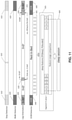
- FIG. 11 is a schematic view showing accelerometer data being processed by various components of the sensing unit in order to determine segments of data in an “out-of-bed” (OOB) state and a “rest-in-bed” state.
- OOB out-of-bed
- FIG. 12 is a schematic view showing that the sleep probability of accelerometer data epochs increases with time within the “rest-in-bed” state, with each subplot of sleep probability being characterized by the mean leg activity feature A and mean leg elevation angle feature ⁇ as determined by processing the accelerometer data; and
- FIG. 13 is a schematic view showing exemplary operation of the novel TENS device, including its user state (i.e., “out-of-bed” state and “rest-in-bed” state), fragmented sleep quality (poor sleep quality) indicator, and modification of the TENS therapy session start time.
- user state i.e., “out-of-bed” state and “rest-in-bed” state
- fragmented sleep quality (poor sleep quality) indicator modification of the TENS therapy session start time.
- FIG. 1 illustrates a novel TENS device 100 formed in accordance with the present invention, with the novel TENS device being shown worn on a user's upper calf 140 .
- a user may wear TENS device 100 on either leg or a user may wear one TENS device 100 on each leg.
- TENS device 100 is shown in greater detail in FIG. 2 and preferably comprises three primary components: a stimulator 105 , a strap 110 , and an electrode array 120 (comprising a cathode electrode and an anode electrode appropriately connected to stimulator 105 as is well known in the art).
- Stimulator 105 preferably comprises three mechanically and electrically inter-connected compartments 101 , 102 , and 103 .
- Compartments 101 , 102 , 103 are preferably inter-connected by hinge mechanisms 104 (only one of which is shown in FIG. 2 ), thereby allowing TENS device 100 to conform to the curved anatomy of a user's leg.
- compartment 102 houses the TENS stimulation circuitry (except for a battery) and user interface elements 106 and 108 .
- Compartment 102 also houses an accelerometer 152 and a gyroscope 163 (see FIG. 4 ), preferably in the form of a semiconductor chip comprising the accelerometer and gyroscope, for detecting user gestures, user leg and body orientation, and user leg and body motion, as will hereinafter be discussed.
- Compartment 102 also houses a real-time clock 505 ( FIG. 4 ).
- compartments 101 and 103 are smaller, auxiliary compartments that house a battery for powering the TENS stimulation circuitry and other circuitry, and other ancillary elements, such as an ambient light sensor or detector 510 ( FIGS. 4 and 6 ) for determining ambient light conditions, and a wireless interface unit of the sort well known in the art (not shown) for allowing TENS device 100 to wirelessly communicate with other elements (e.g., a hand-held electronic device such as a smartphone 860 ).
- a hand-held electronic device such as a smartphone 860
- only one or two compartments may be used for housing all of the TENS stimulation circuitry, battery, and other ancillary elements of the present invention.
- a greater number of compartments are used, e.g., to conform better to the body and to improve user comfort.
- a flexible circuit board is used to distribute the TENS stimulation circuitry and other circuitry more evenly around the leg and thereby reduce bulk.
- a temperature sensor 107 ( FIG. 2 ) is embedded in (or attached to) the strap 110 in order to measure the skin temperature of the user and the measured skin temperature is electrically communicated to the stimulator 105 .
- temperature sensor 107 is housed in compartment 102 (or one of the other compartments 101 , 103 ).
- user interface element 106 preferably comprises a push button for user control of electrical stimulation
- user interface element 108 preferably comprises an LED for indicating stimulation status and for providing other information to the user.
- interface element 108 may comprise multiple LEDs of different colors. Additional user interface elements (e.g., an LCD display, audio feedback through a beeper or voice output, haptic devices such as a vibrating motor, etc.) are also contemplated and are within the scope of the present invention.
- the preferred embodiment of the present invention is designed to be worn on the upper calf 140 of the user as shown in FIG. 1 .
- TENS device 100 comprising stimulator 105 , electrode array 120 , and strap 110 , is secured to upper calf 140 by placing the apparatus in position and then tightening strap 110 .
- additional anatomical locations such as above the knee, on the lower back, and on the upper arm are also contemplated and are also considered to be within the scope of the present invention.
- multiple TENS devices 100 may be worn by a user simultaneously (e.g., one TENS device 100 on each upper calf 140 of the user, one TENS device 100 on the upper calf 140 of a user and another TENS device 100 on the lower back of the user, etc.).
- Constant current source 410 preferably provides an appropriate biphasic waveform (i.e., biphasic stimulation pulses) of the sort well known in the art of TENS therapy.
- biphasic waveform i.e., biphasic stimulation pulses
- the designation of “anode” and “cathode” electrodes is purely notational in the context of a biphasic waveform (i.e., when the biphasic stimulation pulse reverses its polarity in its second phase of the biphasic TENS stimulation, current will be flowing into the user's body via “cathode” electrode 432 and out of the user's body via “anode” electrode 420 ).
- TENS device 100 further comprises (e.g., within compartment 102 ) user state detector 500 for (i) determining the sleep-wake state of the user (i.e., for determining whether a user is in an “out-of-bed” state or a “rest-in-bed” state), (ii) analyzing the sleep of the user, and/or (iii) providing enhanced transcutaneous electrical nerve stimulation (TENS) using the same.
- user state detector 500 for (i) determining the sleep-wake state of the user (i.e., for determining whether a user is in an “out-of-bed” state or a “rest-in-bed” state), (ii) analyzing the sleep of the user, and/or (iii) providing enhanced transcutaneous electrical nerve stimulation (TENS) using the same.
- TENS device 100 further comprises (e.g., within compartment 102 ) user state detector 500 for (i) determining the sleep-wake state of the user (i.e., for determining whether a user is in
- TENS device 100 When the TENS device is secured in position on the user's upper calf, the position and orientation of accelerometer 152 and gyroscope 163 ( FIG. 4 ) of TENS device 100 is fixed relative to the lower limb of the user. Tight mechanical coupling between TENS device 100 and lower limb 140 allows movement of the user's lower limb to be accurately measured by accelerometer 152 and/or gyroscope 163 .
- Such tight mechanical coupling is preferably established through the aforementioned strap 110 .
- tight mechanical coupling may be established through other means, e.g., a flexible band encasing the TENS device.
- a tension gauge 109 FIG. 1
- Regular and robust body movement is more likely the result of user activities during the daytime (e.g., walking during an “out-of-bed” or “wake” state), while quiet or low-level spontaneous movements are more likely during nighttime (e.g., spontaneous leg movement during a “rest-in-bed” or “sleep” state).
- Interactions of body orientation and movement level can also be useful in identifying the sleep-wake state of the user (i.e., thereby enhancing a sleep-wake state classification).
- output from body temperature sensor 107 is used to improve sleep pattern classification results. It has been recognized that body temperature fluctuates with different sleep stages. In particular, body temperature tends to drop after the onset of sleep (i.e., “stage 2” of sleep, when a user is no longer conscious of their surroundings). Incorporating a skin temperature measurement into the sleep monitoring function of TENS device 100 improves the accuracy of the classification of sleep stages and determination of sleep quality made by TENS device 100 (i.e., by processor 515 of TENS device 100 ).
- TENS device 100 may comprise an on-skin detector to confirm that TENS device 100 is firmly seated on the skin of the user.
- an on-skin detector 521 is provided to determine whether and when TENS device 100 is securely placed on the user's upper calf. In the preferred embodiment, and looking now at FIG. 5 , on-skin detector 521 may be provided within TENS device 100 . More particularly, in one preferred form of the invention, a voltage of 20 volts from voltage source 204 is applied to the anode terminal 212 of TENS stimulator 105 by closing the switch 220 .
- On-skin detector 521 is preferably employed in two ways.
- on-skin detector 521 indicates that electrode array 120 of TENS device 100 has become partially or fully detached from the skin of the user
- processor 515 of TENS device 100 will recognize that the data from accelerometer 152 and/or gyroscope 163 may not reliably reflect user leg orientation and leg motion, and user state detector 500 can take appropriate action (e.g., alert the user).
- user state detector 500 can take appropriate action (e.g., alert the user).
- the on-skin detector 521 indicates that TENS device 100 is on the skin of the user, and accelerometer 152 and/or gyroscope 163 is closely coupled to the lower limb of the user
- the data from accelerometer 152 and/or gyroscope 163 may be representative of user leg orientation and user leg motion.
- accelerometer 152 and/or gyroscope 163 is not closely coupled to the lower limb of the user, and the data from accelerometer 152 and/or gyroscope 163 will not be representative of user leg orientation and user leg motion.
- processor 515 uses the accelerometer data from accelerometer 152 and/or data from gyroscope 163 to measure the user's leg orientation, which is highly correlated with body orientation and therefore indicative of the user's recumbent state (and therefore the user's “rest-in-bed” state); and processor 515 uses the accelerometer data from accelerometer 152 to measure the user's leg motion, which is also indicative of the user's sleep-wake state and leg motion activity levels; and processor 515 uses the determinations of user leg orientation and user leg motion to enhance sleep characterization accuracy.
- processor 515 uses the accelerometer data from accelerometer 152 to measure two distinct aspects of the user's leg orientation: leg “elevation” (or the angle of the lower leg relative to the horizontal plane), and leg “rotation” (or the angle of rotation of the lower leg about its own axis).
- Measurement data provided to processor 515 from gyroscope 163 are especially useful in detecting and quantifying angular rotation of the user's leg about the axis of the user's leg.
- Data from the gyroscope 163 are processed similarly to produce data streams with difference sampling rates.
- user state detector 500 is configured to detect leg elevation.
- the present invention uses the leg elevation, which is computed by processor 515 of user state detector 500 , based on measurement data from accelerometer 152 and/or gyroscope 163 when TENS device 100 is placed on the user's upper calf 140 ( FIG. 1 ).
- accelerometer 152 and/or gyroscope 163
- FIG. 6 accelerometer 152 (and/or gyroscope 163 ) is located on the circuit board 151 of the TENS circuitry housed inside compartment 102 , so that the accelerometer's 3-axis directions, shown at 153 in FIG.
- the acceleration measured along the y-axis will include not only the projection of gravity onto that axis, but also a contribution from motion:
- a y ( t ) ⁇ sin
- the specific ⁇ sign depends upon the TENS device placement on upper calf 140 and is fixed for each placement.
- the motion component m(t) is considered “noise” in the context of determining leg elevation, and will have zero mean over a sufficiently large window.
- Step 1 Set a target angle threshold ⁇ 0 (this is the “Threshold1” shown at step 910 in FIG. 10 ) for the angle ⁇ so that
- the target angle threshold ⁇ 0 is set to 30°.
- Step 2 Define non-overlapping windows of length N, called “epochs”.
- the time at the end of each epoch is denoted T.
- the mean A y,T and the standard error of the mean SE Y,T are calculated based on samples in each epoch.
- processor 515 of user state detector 500 requires [
- + ⁇ SE Y,T ] ⁇ A ⁇ . In a preferred embodiment ⁇ 3, but other values are possible.
- processor 515 of user state detector 500 may be configured to detect instantaneous activity.
- ⁇ I (t) the vector magnitude of acceleration
- processor 515 of user state detector 500 uses this instantaneous acceleration ⁇ I (t) for the actigraphy calculations.
- ⁇ I (t) A ⁇ X ⁇ ( t ) 2 + A ⁇ Y ⁇ ( t ) 2 + A ⁇ Z ⁇ ( t ) 2
- processor 515 of user state detector 500 uses this instantaneous acceleration ⁇ I (t) for the actigraphy calculations.
- calculations based on other combinations of acceleration axes may also be used. For example, rather than combining all three axes equally as done with ⁇ I (t) as defined above, only some axes may be used, or certain axes may be contrasted through subtraction.
- processor 515 of user state detector 500 may be configured to detect leg movement which is more likely to occur during sleep when the user is determined to be in a “rest-in-bed” state.
- the instantaneous acceleration ⁇ I (t) is a time series comprised of brief events, such as leg movements known to occur during normal and abnormal sleep, and sustained activity, such as occurs during walking, running, or climbing stairs.
- leg movements (LM) are computed in a manner that is consistent with the detection of periodic leg movements (PLM) defined in the clinical literature (Bonnet et al, 1993; Zucconi et al, 2006), however, other approaches to detecting brief leg movements are possible and are considered to be within the scope of the present invention.
- LM leg movement
- Step 3 Compute instantaneous acceleration ⁇ I (t) for each time instant.
- LM leg movement
- the top panel ( 810 ) in FIG. 8 shows an example of the leg movement (LM) detection algorithm applied to real data.
- Time is measured in instants, i.e., steps of 0.1 second.
- the dots, and the line 812 connecting them, are the instantaneous accelerations ⁇ I (t).
- the vertical line 814 shows the instant when ⁇ I (t) first went below the second threshold 816 for more than 0.5 second so the LM period was terminated.
- the net result is an LM period with a duration of 89 instants (i.e., 8.9 seconds).
- processor 515 of user state detector 500 is configured to function as a body roll detector when TENS device 100 determines that the user is in a “rest-in-bed” state.
- the TENS device 100 when the TENS device 100 ( FIG. 9 ) is worn on the lower leg (i.e., upper calf 140 ) of a user, its accelerometer 152 will sense the projection of the gravity in its x-z plane when the user is in a recumbent position.
- the angle ⁇ between the device x-axis and the gravity vector ⁇ g can be calculated based on the projected gravity value in the x and z axis.
- Axis z′ is aligned with the “big toe” direction of the user's leg to which the TENS device 100 is attached.
- Angle ⁇ between the device z-axis and the leg x′-axis is fixed when the TENS device is securely placed on the lower leg (i.e., upper calf 140 ) of the user.
- a body roll detection algorithm is implemented by processor 515 in user state detector 500 , using only the angle change ⁇ , in the following manner:
- Step 1 For each LM period detected, select the raw acceleration vector A(t) in short windows before and after the leg movement. In a present invention, this window is an instant (0.1 seconds).
- the inverse tangent function a tan 2 returns an angle in the range ⁇ 180° ⁇ (t) ⁇ 180°, i.e., a result in all four possible quadrants.
- this difference is put in the range ⁇ 180° ⁇ 180°, i.e., if ⁇ >180° then subtract 360°, but if ⁇ 180° then add 360°.
- Step 5 Compare the absolute value
- the middle panel ( 820 ) in FIG. 8 shows this body roll detection algorithm applied to real data.
- the acceleration values A x (t), A y (t), and A z (t) are plotted in traces 821 , 822 , and 823 .
- a x (t) and A z (t) show significant activities, especially between time instants 30 and 70 .
- the steady state value for A x (t) changed from +1 g (before the LM period) to ⁇ 1 g (after the LM period), suggesting a body roll event.
- the bottom panel ( 830 ) of FIG. 8 shows the calculation of the elevation angle ⁇ ( 833 ) and the rotation angle ⁇ ( 834 ) for each instant.
- the elevation angle ⁇ 0 throughout the event, consistent with the lower leg being in recumbent elevation.
- the rotation angle ⁇ changes from ⁇ +90° (indicated by the empty circle 831 ) to ⁇ 88° (indicated by the filled circle 832 ).
- the angular change is ⁇ 178°, consistent with a (rightward) roll of the entire body.
- body rolls may be reported directly to the user to inform them about their sleep patterns.
- body roll events may be brief, the associated increase in activity may not be evident in the epoch average of activity, and therefore may not cause that epoch to be classified as awake. Although rolling over in bed may not indicate an awake state, it does indicate momentarily restless sleep.
- This novel approach for detecting body rolls by evaluating changes in roll angles associated with brief leg movement (LM) permits the differentiation of leg movement associated with no body rolls from leg movement associated with body rolls, and thus provides a finer description of sleep patterns that are useful to the user and their healthcare providers.
- a body roll detection algorithm is implemented by processor 515 of user state detector 500 using the angle change ⁇ in the following manner.
- processor 515 of user state detector 500 uses the angle change ⁇ in the following manner.
- the threshold for detecting a body roll may be adjusted depending upon the leg on which the device is placed. That is to say, in addition to the magnitude of the change ⁇ , the value of the leg rotation angle ⁇ before and after the leg movement (LM), and the sign of the angle change ⁇ across the leg movement (LM), may be used to improve performance of the body roll detector.
- gyroscope measurements i.e., data from gyroscope 163
- processing of angular velocity data of the leg e.g., via processor 515 of user state detector 500 of TENS device 100
- rotational angle changes derived from measurements i.e., data
- data from accelerometer 152 and data from gyroscope 163 are combined together and processed by processor 515 of user state detector 500 of TENS device 100 in order to improve the performance of the body roll detector.
- processor 515 of user state detector 500 may be configured to function as a static body rotational position detector.
- leg rotational position is highly correlated with body position, e.g., when sleeping on one's back, the toes of either foot are pointed upward above the horizontal plane to varying degrees, not likely exactly on the horizontal plane, and never below the horizontal plane.
- the time scale of an “epoch” equal to one minute, and the epoch-averaged non-high-pass filtered acceleration values ⁇ X,T (t), ⁇ Y,T (t), and ⁇ Z,T (t) were introduced above in the section entitled “Leg Elevation Detection”. Because it is sufficient to report the time spent sleeping on the back at the resolution of one minute, these epoch-averaged acceleration values may be advantageously used in the following manner to detect static body rotational position.
- ⁇ T a tan 2 ⁇ X,T (t), ⁇ Z,T (t) ⁇ as before, where ⁇ X,T (t) and ⁇ Z,T (t) are raw (i.e., not high-pass filtered) accelerations averaged over an epoch T.
- ⁇ T the angle of the toes relative to the vertical.
- the relation between ⁇ T and ⁇ T depends upon the rotational placement of the TENS device on the upper calf of the user, denoted a. Because the electrode gel 444 is sticky and the strap 110 is supportive, the TENS device does not move on the user's leg once it is placed onto the upper calf 140 , therefore the angle ⁇ is constant as long as the TENS device is on the leg of the user.
- the double-primed coordinate system i.e., x′′, y′′, z′′, with y′′ not being seen in FIG. 9 since it extends down the axis of the leg
- the single-primed coordinate system i.e., x′, y′, z′, with y′ not being seen in FIG. 9 since it extends down the axis of the leg
- the unprimed coordinate system i.e., x, y, z, with y not being seen in FIG.
- the Earth coordinate system has its z′′-axis along the vertical
- the leg coordinate system has its z′-axis in the direction of the toes
- the leg rotational angle ⁇ is the angle between the Earth x′′-axis and leg x′-axis.
- the TENS device angle ⁇ is the location of the TENS device on the leg measured from the leg x′-axis.
- the following simple procedure is used by processor 515 of user state detector 500 to determine whether the user is on-back through an estimation of the angle ⁇ when the user is in a “rest-in-bed” state.
- Step 1 The user places the TENS device on the lower leg of the user and fastens the strap 110 snugly around their upper calf 140 , lies recumbent with the leg nearly horizontal, points their toes vertically upward, and remains still.
- Step 2 The user indicates to the TENS device that the aforementioned conditions have been met.
- This indication may take the form of a series of button presses (e.g., with button 106 ), a series of taps on compartment 102 detected by the accelerometer 152 , or an indication on a smartphone 860 in communication with the TENS device 100 .
- Step 5 Define a range of values for ⁇ T that correspond to the user lying or sleeping on their back.
- the thresholds (which would reside at step 930 in FIG. 10 ) depend upon the leg on which the device is placed. For example, if the device is placed on the left leg, the most likely range of angles while lying on the back is 0° ⁇ T ⁇ 80°.
- the device is placed on the right leg, the most likely range of angles while lying on the back is ⁇ 80° ⁇ T ⁇ 0°.
- Using asymmetric thresholds to accommodate the asymmetry of the normal range of motion of the leg relative to the torso may improve the accuracy of the static body rotational position detector.
- Step 6 If the user with sleep apnea selects this option for TENS device 100 , then when the user is determined to be asleep, i.e., recumbent with low activity, the TENS device notifies the user if they are on their back for more than some set amount of time, e.g., a few minutes.
- This indication can be in the form of a vibration of the TENS device itself, or an alarm on their smartphone 860 , for example.
- Step 7 After determining the span(s) of minutes in which the user was likely to be asleep, i.e., recumbent with low activity, determine the fraction of minutes in which the user was determined to be on their back. Report this percentage to this user, e.g., with smartphone 860 .
- the 3-axis directions of the accelerometer 152 are known and are fixed in relationship to the lower leg when TENS device 100 is placed on the upper calf 140 of a user: the y-axis is aligned longitudinally along the longitudinal axis of the lower leg of the user; the x-axis is disposed tangential to the surface of the lower leg of the user and perpendicular to the y-axis, and the z-axis points radially away from the surface of the lower leg of the user. Looking now at FIG.
- the elevation angle ⁇ ( 172 ) represents the angle between the positive accelerometer y-axis direction ( 174 ) and the true horizontal plane ( 170 ).
- processor 515 of user state detector 500 of TENS device 100 can detect when the user is in an upright position, and analyzes the temporal pattern of the acceleration data in order to identify steps (i.e., 610 in FIG. 11 ) associated with walking (see, for example, Susi M, Renaudin V, and Lachapelle G, Motion mode recognition and step detection algorithms for mobile phone users. Sensors, 2013:13(2):139-1562).
- Processor 515 of user state detector 500 of TENS device 100 can also detect sequences of steps taken by a user in order to determine when the user is walking (i.e., 620 in FIG. 11 ). Individual steps taken by a user may be detected falsely by processor 515 of user state detector 500 of TENS device 100 (e.g., due to other leg movement), however, the “walk detector” function of processor 515 is highly specific, inasmuch as the “walk detector” function of processor 515 requires that the user's detected steps occur regularly and with specific time intervals, in order for processor 515 to determine that the user is walking.
- each one-minute epoch is classified as “upright” (i.e., 630 and 631 in FIG. 11 ) if data from accelerometer 152 is processed by processor 515 of user state detector 500 of TENS device 10 and indicates that the absolute value of the mean elevation angle
- Contiguous sets of the “upright” epochs in which at least one epoch includes walking or at least two epochs include stepping are classified as “out-of-bed” (OOB) events 640 , 641 ( FIG. 11 ). This use of step and walk detectors makes the detection of “out-of-bed” (OOB) events more specific and more accurate.
- a user can put their knees up in bed without falsely triggering an “out-of-bed” (OOB) event.
- OOB out-of-bed
- epochs for which the mean elevation ⁇ >75° are classified as “standing” (i.e., the user is standing upright), and are also classified as “out-of-bed” (OOB) events 641 .
- Other values for these parameters are possible and are considered to be within the scope of the present invention.
- each sleep segment 650 is characterized by three basic features: mean activity A, mean elevation ⁇ , and duration D.
- a given sleep segment 650 which are determined by processor 515 using data from accelerometer 152 and/or gyroscope 163 , are passed to a classifier 655 ( FIG. 11 ) which determines whether the given segment meets requirements of sleep (e.g., “goodness-of-fit” of the segment feature parameters to their target ranges).
- requirements of sleep e.g., “goodness-of-fit” of the segment feature parameters to their target ranges.
- the functions of classifier 655 may be implemented by appropriate software programming running on the aforementioned processor 515 of user state detector 500 of TENS device 100 , or the functions of classifier 655 may be implemented by another microprocessor of the sort well known in the art with appropriate software programming for providing the functions disclosed herein.
- each segment feature is compared against its own predetermined threshold.
- two or more segment features are evaluated together using a linear or nonlinear classifier function.
- K th 0, in which case K>0 is equivalent to the condition P(Sleep)>P(Wake).
- K th 0.5 to make the classifier more specific for sleep (i.e., “Asleep”).
- Other classifiers and values for these parameters are possible, and are considered to fall within the scope of the present invention.
- the feature target range(s) and classifier threshold value(s) can be applicable to all users, or tailored to selected group of users, or specific to an individual user, or a combination thereof.
- the feature target range(s) and classifier threshold values may start out (i.e., be preprogrammed) as population default values. These population default values can be updated based on specific indications by the user (e.g., “I am a light sleeper”). Finally, the values can be further refined based on actual user sleep behavior previously measured by TENS device 100 (e.g., a particular user's likely time of day for sleep calculation is modified by the user's prior history of sleep onset time).
- a sleep session 660 is a contiguous time interval during which the user is in bed for sleeping.
- a given sleep session 660 corresponds to the standard clinical definition of “time in bed”.
- a given sleep session 660 it is detected as a series of sleep segments for which the starting and ending segments have K>K th .
- This definition allows a given sleep session 660 to include some “out-of-bed” (OOB) events as may normally occur during the night, and two “out-of-bed” (OOB) events may be separated by a brief sleep segment, with K ⁇ K th .
- OOB out-of-bed
- some sleep segments at the beginning of the night may have K>K th , however, the corresponding K values will typically be lower than those of sleep segments later in the night which are more clearly sleep.
- a given sleep session 660 starts with the first sleep segment having a more stringent requirement of K>0.75, and ends when an “out-of-bed” (OOB) event is detected which lasts more than 15 minutes, with the additional condition that the last sleep segment included must have K>K th .
- OOB out-of-bed
- Other logical schemes and values for these parameters for the first sleep segment, the last sleep segment and intermediate sleep segments are possible and fall within the scope of the present invention.
- Some users may have one (or more) long “out-of-bed” (OOB) event(s) during a given sleep session 660 (i.e., during the night while the user is sleeping) which results in TENS device 100 registering two or more sleep sessions 660 .
- OOB out-of-bed
- two sleep sessions 660 lasting at least 3 hours each and separated by an “out-of-bed” (OOB) event lasting less than 1 hour may be merged together to form one sleep session 660 in which the intervening “out-of-bed”(OOB) event is classified as “awake”.
- sleep metrics are computed by TENS device 100 (e.g., by aforementioned processor 515 of user state detector 500 of TENS device 100 ) and reported to the user.
- the TENS device 100 uses the information available for each minute (i.e., each epoch) to estimate the probability that the user is sleeping, P(Sleep).
- sleep probability i.e., P(Sleep)
- P(Sleep) as a function of time depends on the same three features used to assign a K value to a sleep segment as described above (i.e., mean activity A, mean elevation ⁇ , and duration D). Because P(Sleep) depends in part upon the duration of a particular sleep segment, P(Sleep) increases gradually following an “out-of-bed” (OOB) event. P(Sleep) increases with time more quickly if TENS device 100 measures a lower mean activity level A and a mean elevation ⁇ value closer to zero.
- OOB out-of-bed
- a flag i.e., a variable
- AsleepForStim is defined to indicate the real-time sleep state of the user in order to control the stimulation intensity (e.g., a flag “AsleepForStim” is set by the software running on processor 515 of TENS device 100 ).
- OOB out-of-bed
- the TENS device 100 computes P(Sleep).
- P(Sleep)>0.5 the AsleepForStim flag is set “true”.
- the AsleepForStim flag remains “true” until an “out-of-bed” (OOB) event is detected and has lasted for at least 15 minutes, then the AsleepForStim flag is set “false”. Consequently, the AsleepForStim flag will generally be “true” throughout a given sleep session 660 , including any brief “out-of-bed” (OOB) events during a given night (i.e., a given sleep session).
- TENS device 100 checks the value of the AsleepForStim flag (i.e., to determine whether the flag is set to “true” or “false”). If the AsleepForStim flag is “false”, then the stimulation level will be unchanged. If AsleepForStim flag is “true”, the stimulation level will be reduced (unless the user chooses to disable this adaptive stimulation feature of TENS device 100 ).
- AsleepForStim flag is “true” and the user enables the adaptive therapy onset mode (i.e., enables TENS device 100 to deliver adaptive stimulation depending upon user wake/sleep state)
- scheduled onset time for next therapy may be postponed based on a real-time measure of sleep quality called “sleep fragmentation”, as will hereinafter be discussed in further detail.
- Sleep fragmentation refers to brief arousals or awakenings that disrupt the normal sleep architecture, and often occurs often in people experiencing chronic pain.
- the present invention provides the user with the option to start therapy during sleep only when sleep is fragmented. This option balances the goals of using TENS device 100 to reduce pain and improve sleep, while minimizing the possibility that the sensation of stimulation may itself disturb sleep.
- the TENS device 100 checks the value of the flag for AsleepForStim. If the flag for AsleepForStim is “true” and if TENS device 100 has been on the user's skin for at least an hour (i.e., electrode array 120 of TENS device 100 has been in contact with the user's skin for at least an hour), processor 515 of TENS device 100 determines a value for a flag called “SleepFragmented” in the prior hour. If the SleepFragmented flag is determined to be “false”, i.e., if sleep is very restful, then onset of stimulation is postponed. TENS device 100 then checks the flag for SleepFragmented status every 5 minutes.
- TENS device 100 When either the flag for AsleepForStim is “false” (i.e., the user is awake), or the flag for SleepFragmented is “true” (i.e., sleep is no longer restful), stimulation by TENS device 100 is permitted to start. In this way, stimulation is delivered by TENS device 100 only as needed.
- a user is considered to be awake if the user is either “out-of-bed” (OOB), or if the user's mean activity in a one-minute epoch A>0.01.
- OOB output-of-bed
- a more sensitive measure of brief arousals available from accelerometer data is leg movements (LM), computed using the 10 Hz activity stream, in which the effect of gravity has been removed.
- LM leg movement
- a leg movement (LM) is defined as an event in which the activity detected by TENS device 100 exceeds a predetermined threshold A2 and then falls below a predetermined threshold A1.
- epochs with one or more leg movement (LM) events normally include awake epochs as well as epochs with brief arousals.
- LM leg movement
- the aforementioned Boolean flag called SleepFragmented is “true” if and only if, in the last hour, the fraction of epochs with one or more leg movement (LM) is greater than 40%.
- Other definitions of sleep fragmentation and values of these parameters are possible and considered to fall within the scope of the present invention.
- these values may be set by TENS device 100 , or these values may be modified by the user.
- FIG. 13 provides an illustrative example of the adaptive behavior of the therapy onset based on user sleep state.
- Default therapy sessions are shown in trace 691 .
- User “out-of-bed” (OOB) events are marked in trace 692 (i.e., when the trace value is equal to 1).
- Sleep probability based on user activity level, leg elevation, and “out-of-bed” (OOB) events is shown as trace 693 .
- the AsleepForStim flag is shown as trace 694 (i.e., the AsleepForStim flag is “true” when the trace value equals 1 and “false” when trace value equals 0).
- the SleepFragmented flag is shown as trace 695 (i.e., the SleepFragmented flag is “true” when the trace value equals 1 and “false” when trace value equals 0).
- the OnsetDelay flag (which is the logic inverse of the SleepFragmented flag) is shown as trace 696 (i.e., the OnsetDelay flag is “true” when the trace value equals 1 and “false” when trace value equals 0).
- trace 697 which is the logic inverse of the SleepFragmented flag
- the sleep probability trace 693 is also shown in FIG. 13 , with P(Sleep)>0.5 corresponding to “true” (i.e., “1”) for the first time at a point near 132 minutes.
- the AsleepForStim flag trace 694 turns true (i.e., “1”) at 132 minutes, and remains true, even during the brief “out-of-bed” (OOB) event from 351-357 minutes (shown in trace 692 ).
- An extended “out-of-bed” (OOB) event starts at 642 minutes, and the AsleepForStim flag becomes “false” at 662 minutes (shown in trace 694 ).
- the onset of the scheduled therapy session 682 which would have occurred at the 240 th minute is delayed to the 360 th minute.
- epoch when a therapy session was scheduled to start (i.e., at the time instance when the value of trace 691 transitions from 0 to 1), if the OnsetDelay flag (trace 696 ) is still “true”, the start of the therapy session is delayed. Since the OnsetDelay flag 696 becomes true at 171 minutes, and becomes false at 359 minutes, the scheduled therapy session (trace 691 ) at the 240 th minute is delayed, and an actual therapy session 684 begins at the 360 th minute.
- the present invention provides a transcutaneous electrical nerve stimulator with automatic assessment of sleep patterns and sleep characteristics based on monitoring of leg activities and leg orientations.
- Leg orientations include leg elevation and leg rotation state, and changes in leg elevation and leg rotation states.
- the TENS stimulator may be preprogrammed to modify its operations in response to the detected user leg activities and leg positions during bed time. Individual aspects of the TENS stimulator operations (e.g., stimulation onset, stimulation pulse intensity, and stimulation session duration) are modified based on specific sleep characteristics. However, these operating parameters can be modified simultaneously.
- leg orientation and leg activities are used to assess sleep quality and sleep position, all are important aspects to improve sleep and health.
- Leg activity patterns can also be used to diagnose sleep disorders such as periodic leg movement and the TENS stimulator can be used to alleviate excessive leg movement activities that are disruptive to sleep.
- the feedback provided to the user can be in the form of mechanical vibrations from a vibration motor (i.e., haptic feedback).
- the feedback can also be in the form of electrical stimulation (i.e., a stimulation pulse delivered by TENS device 100 ).
- feedback to the user is provided when a minimum time period of good sleep is achieved and the sleep quality is transitioning from non-fragmented sleep to fragmented sleep.
- the present invention can also be realized without the nerve stimulation functionality.
- Body movement and position can be monitored and quantified using the present invention without the need of nerve stimulation.
- the monitoring apparatus can also be placed in other body positions like upper arm of either limb.
Abstract
Description
-
- (A) is a continuation of prior U.S. patent application Ser. No. 14/610,757, filed Jan. 30, 2015 by NeuroMetrix, Inc. and Shai N. Gozani et al. for APPARATUS AND METHOD FOR RELIEVING PAIN USING TRANSCUTANEOUS ELECTRICAL NERVE STIMULATION, which patent application in turn:
- (i) is a continuation of prior U.S. patent application Ser. No. 13/678,221, filed Nov. 15, 2012 by NeuroMetrix, Inc. and Shai N. Gozani et al. for APPARATUS AND METHOD FOR RELIEVING PAIN USING TRANSCUTANEOUS ELECTRICAL NERVE STIMULATION, which in turn claims benefit of:
- (a) prior U.S. Provisional Patent Application Ser. No. 61/560,029, filed Nov. 15, 2011 by Shai N. Gozani for SENSUS OPERATING MODEL; and
- (b) prior U.S. Provisional Patent Application Ser. No. 61/657,382, filed Jun. 8, 2012 by Shai N. Gozani et al. for APPARATUS AND METHOD FOR RELIEVING PAIN USING TRANSCUTANEOUS ELECTRICAL NERVE STIMULATION;
- (i) is a continuation of prior U.S. patent application Ser. No. 13/678,221, filed Nov. 15, 2012 by NeuroMetrix, Inc. and Shai N. Gozani et al. for APPARATUS AND METHOD FOR RELIEVING PAIN USING TRANSCUTANEOUS ELECTRICAL NERVE STIMULATION, which in turn claims benefit of:
- (A) is a continuation of prior U.S. patent application Ser. No. 14/610,757, filed Jan. 30, 2015 by NeuroMetrix, Inc. and Shai N. Gozani et al. for APPARATUS AND METHOD FOR RELIEVING PAIN USING TRANSCUTANEOUS ELECTRICAL NERVE STIMULATION, which patent application in turn:
-
- (A) is a continuation-in-part of prior U.S. patent application Ser. No. 14/794,588, filed Jul. 8, 2015 by NeuroMetrix, Inc. and Xuan Kong et al. for MEASURING THE “ON-SKIN” TIME OF A TRANSCUTANEOUS ELECTRICAL NERVE STIMULATOR (TENS) DEVICE IN ORDER TO MINIMIZE SKIN IRRITATION DUE TO EXCESSIVE UNINTERRUPTED WEARING OF THE SAME, which patent application:
- (i) is a continuation-in-part of prior U.S. patent application Ser. No. 14/610,757, filed Jan. 30, 2015 by NeuroMetrix, Inc. and Shai N. Gozani et al. for APPARATUS AND METHOD FOR RELIEVING PAIN USING TRANSCUTANEOUS ELECTRICAL NERVE STIMULATION, which patent application:
- (a) is a continuation of prior U.S. patent application Ser. No. 13/678,221, filed Nov. 15, 2012 by NeuroMetrix, Inc. and Shai N. Gozani et al. for APPARATUS AND METHOD FOR RELIEVING PAIN USING TRANSCUTANEOUS ELECTRICAL NERVE STIMULATION, which patent application claims benefit of:
- (1) prior U.S. Provisional Patent Application Ser. No. 61/560,029, filed Nov. 15, 2011 by Shai N. Gozani for SENSUS OPERATING MODEL; and
- (2) prior U.S. Provisional Patent Application Ser. No. 61/657,382, filed Jun. 8, 2012 by Shai N. Gozani et al. for APPARATUS AND METHOD FOR RELIEVING PAIN USING TRANSCUTANEOUS ELECTRICAL NERVE STIMULATION;
- (a) is a continuation of prior U.S. patent application Ser. No. 13/678,221, filed Nov. 15, 2012 by NeuroMetrix, Inc. and Shai N. Gozani et al. for APPARATUS AND METHOD FOR RELIEVING PAIN USING TRANSCUTANEOUS ELECTRICAL NERVE STIMULATION, which patent application claims benefit of:
- (ii) is a continuation-in-part of U.S. patent application Ser. No. 14/269,887, filed May 5, 2014 by NeuroMetrix, Inc. and Thomas Ferree et al. for TRANSCUTANEOUS ELECTRICAL NERVE STIMULATOR WITH USER GESTURE DETECTOR AND ELECTRODE-SKIN CONTACT DETECTOR, WITH TRANSIENT MOTION DETECTOR FOR INCREASING THE ACCURACY OF THE SAME, which patent application:
- (a) is a continuation-in-part of prior U.S. patent application Ser. No. 14/230,648, filed Mar. 31, 2014 by Neurometrix, Inc. and Shai Gozani et al. for DETECTING CUTANEOUS ELECTRODE PEELING USING ELECTRODE-SKIN IMPEDANCE, which claims benefit of:
- (1) prior U.S. Provisional Patent Application Ser. No. 61/806,481, filed Mar. 29, 2013 by NeuroMetrix, Inc. and Shai Gozani for DETECTING ELECTRODE PEELING BY RELATIVE CHANGES IN SKIN-ELECTRODE IMPEDANCE;
- (b) is a continuation-in-part of prior U.S. patent application Ser. No. 14/253,628, filed Apr. 15, 2014 by Neurometrix, Inc. and Shai Gozani et al. for TRANSCUTANEOUS ELECTRICAL NERVE STIMULATOR WITH AUTOMATIC DETECTION OF USER SLEEP-WAKE STATE, which claims benefit of:
- (1) prior U.S. Provisional Patent Application Ser. No. 61/811,864, filed Apr. 15, 2013 by Neurometrix, Inc. and Shai Gozani for TRANSCUTANEOUS ELECTRICAL NERVE STIMULATOR WITH AUTOMATIC DETECTION OF PATIENT SLEEP-WAKE STATE;
- (c) claims benefit of prior U.S. Provisional Patent Application Ser. No. 61/819,159, filed May 3, 2013 by Neurometrix, Inc. and Thomas Ferree et al. for TAP DETECTOR WITH HIGH SENSITIVITY AND SPECIFICITY FOR A WEARABLE TRANSCUTANEOUS ELECTRICAL NERVE STIMULATOR; and
- (d) claims benefit of prior U.S. Provisional Patent Application Ser. No. 61/858,150, filed Jul. 25, 2013 by Neurometrix, Inc. and Andres Aguirre et al. for MOVEMENT REGULATED TRIP CONDITIONS IN A WEARABLE TRANSCUTANEOUS ELECTRICAL NERVE STIMULATOR;
- (a) is a continuation-in-part of prior U.S. patent application Ser. No. 14/230,648, filed Mar. 31, 2014 by Neurometrix, Inc. and Shai Gozani et al. for DETECTING CUTANEOUS ELECTRODE PEELING USING ELECTRODE-SKIN IMPEDANCE, which claims benefit of:
- (iii) claims benefit of prior U.S. Provisional Patent Application Ser. No. 62/021,807, filed Jul. 8, 2014 by Neurometrix, Inc. and Xuan Kong et al. for MEASURING TENS DEVICE ON-SKIN TIME TO PREVENT AND MINIMIZE SKIN IRRITATION;
- (i) is a continuation-in-part of prior U.S. patent application Ser. No. 14/610,757, filed Jan. 30, 2015 by NeuroMetrix, Inc. and Shai N. Gozani et al. for APPARATUS AND METHOD FOR RELIEVING PAIN USING TRANSCUTANEOUS ELECTRICAL NERVE STIMULATION, which patent application:
- (B) claims benefit of prior U.S. Provisional Patent Application Ser. No. 62/213,978, filed Sep. 3, 2015 by Neurometrix, Inc. and Thomas Ferree et al. for TRANSCUTANEOUS ELECTRICAL NERVE STIMULATOR WITH AUTOMATIC DETECTION OF LEG ORIENTATION AND ROTATION FOR ENHANCED SLEEP ANALYSIS; and
- (C) claims benefit of prior U.S. Provisional Patent Application Ser. No. 62/101,029, filed Jan. 8, 2015 by Neurometrix, Inc. and Shai Gozani et al. for METHOD AND APPARATUS FOR USING TRANSCUTANEOUS ELECTRICAL NERVE STIMULATION TO AID SLEEP;
- (A) is a continuation-in-part of prior U.S. patent application Ser. No. 14/794,588, filed Jul. 8, 2015 by NeuroMetrix, Inc. and Xuan Kong et al. for MEASURING THE “ON-SKIN” TIME OF A TRANSCUTANEOUS ELECTRICAL NERVE STIMULATOR (TENS) DEVICE IN ORDER TO MINIMIZE SKIN IRRITATION DUE TO EXCESSIVE UNINTERRUPTED WEARING OF THE SAME, which patent application:
A y(t)=±sin|θ(t)|+m(t) [in unit of g]
where t is time, and m(t) is the contribution due to leg motion. The specific ±sign depends upon the TENS device placement on
In a preferred embodiment of the present invention,
β=180−α−φ
Because the angle α is fixed, the leg rotation angle β can be derived from the angle φ as measured by the
Claims (38)
Priority Applications (1)
| Application Number | Priority Date | Filing Date | Title |
|---|---|---|---|
| US16/459,855 US11247040B2 (en) | 2011-11-15 | 2019-07-02 | Dynamic control of transcutaneous electrical nerve stimulation therapy using continuous sleep detection |
Applications Claiming Priority (20)
| Application Number | Priority Date | Filing Date | Title |
|---|---|---|---|
| US201161560029P | 2011-11-15 | 2011-11-15 | |
| US201261657382P | 2012-06-08 | 2012-06-08 | |
| US13/678,221 US8948876B2 (en) | 2011-11-15 | 2012-11-15 | Apparatus and method for relieving pain using transcutaneous electrical nerve stimulation |
| US201361806481P | 2013-03-29 | 2013-03-29 | |
| US201361811864P | 2013-04-15 | 2013-04-15 | |
| US201361819159P | 2013-05-03 | 2013-05-03 | |
| US201361858150P | 2013-07-25 | 2013-07-25 | |
| US14/230,648 US9474898B2 (en) | 2013-03-29 | 2014-03-31 | Detecting cutaneous electrode peeling using electrode-skin impedance |
| US14/253,628 US10279179B2 (en) | 2013-04-15 | 2014-04-15 | Transcutaneous electrical nerve stimulator with automatic detection of user sleep-wake state |
| US14/269,887 US9827420B2 (en) | 2013-03-29 | 2014-05-05 | Transcutaneous electrical nerve stimulator with user gesture detector and electrode-skin contact detector, with transient motion detector for increasing the accuracy of the same |
| US201462021807P | 2014-07-08 | 2014-07-08 | |
| US201562101029P | 2015-01-08 | 2015-01-08 | |
| US14/610,757 US9656070B2 (en) | 2011-11-15 | 2015-01-30 | Apparatus and method for relieving pain using transcutaneous electrical nerve stimulation |
| US14/794,588 US9675801B2 (en) | 2011-11-15 | 2015-07-08 | Measuring the “on-skin” time of a transcutaneous electrical nerve stimulator (TENS) device in order to minimize skin irritation due to excessive uninterrupted wearing of the same |
| US201562213978P | 2015-09-03 | 2015-09-03 | |
| US14/980,041 US9731126B2 (en) | 2011-11-15 | 2015-12-28 | Transcutaneous electrical nerve stimulator with automatic detection of leg orientation and leg motion for enhanced sleep analysis, including enhanced transcutaneous electrical nerve stimulation (TENS) using the same |
| US201662361693P | 2016-07-13 | 2016-07-13 | |
| US15/602,611 US10780269B2 (en) | 2011-11-15 | 2017-05-23 | Apparatus and method for relieving pain using transcutaneous electrical nerve stimulation |
| US15/648,632 US10335595B2 (en) | 2011-11-15 | 2017-07-13 | Dynamic control of transcutaneous electrical nerve stimulation therapy using continuous sleep detection |
| US16/459,855 US11247040B2 (en) | 2011-11-15 | 2019-07-02 | Dynamic control of transcutaneous electrical nerve stimulation therapy using continuous sleep detection |
Related Parent Applications (1)
| Application Number | Title | Priority Date | Filing Date |
|---|---|---|---|
| US15/648,632 Continuation US10335595B2 (en) | 2011-11-15 | 2017-07-13 | Dynamic control of transcutaneous electrical nerve stimulation therapy using continuous sleep detection |
Publications (2)
| Publication Number | Publication Date |
|---|---|
| US20200030604A1 US20200030604A1 (en) | 2020-01-30 |
| US11247040B2 true US11247040B2 (en) | 2022-02-15 |
Family
ID=80214264
Family Applications (1)
| Application Number | Title | Priority Date | Filing Date |
|---|---|---|---|
| US16/459,855 Active 2032-12-31 US11247040B2 (en) | 2011-11-15 | 2019-07-02 | Dynamic control of transcutaneous electrical nerve stimulation therapy using continuous sleep detection |
Country Status (1)
| Country | Link |
|---|---|
| US (1) | US11247040B2 (en) |
Cited By (8)
| Publication number | Priority date | Publication date | Assignee | Title |
|---|---|---|---|---|
| US20180132757A1 (en) * | 2016-11-11 | 2018-05-17 | Neurometrix, Inc. | Apparatus and method for activity monitoring, gait analysis, and balance assessment for users of a transcutaneous electrical nerve stimulation (tens) device |
| WO2022235516A1 (en) * | 2021-05-06 | 2022-11-10 | Neurometrix, Inc. | Apparatus and method for automated control of a transcutaneous electrical nerve stimulation (tens) device based on tens user's activity type, level and duration |
| US11596785B2 (en) | 2015-09-23 | 2023-03-07 | Cala Health, Inc. | Systems and methods for peripheral nerve stimulation in the finger or hand to treat hand tremors |
| US11730959B2 (en) | 2013-03-29 | 2023-08-22 | Neurometrix, Inc. | Apparatus and method for button-free control of a wearable transcutaneous electrical nerve stimulator using interactive gestures and other means |
| US11857778B2 (en) | 2018-01-17 | 2024-01-02 | Cala Health, Inc. | Systems and methods for treating inflammatory bowel disease through peripheral nerve stimulation |
| US11883661B2 (en) | 2018-12-07 | 2024-01-30 | Neurometrix, Inc. | Intelligent determination of therapeutic stimulation intensity for transcutaneous electrical nerve stimulation |
| US11890468B1 (en) | 2019-10-03 | 2024-02-06 | Cala Health, Inc. | Neurostimulation systems with event pattern detection and classification |
| US11918806B2 (en) | 2016-01-21 | 2024-03-05 | Cala Health, Inc. | Systems, methods and devices for peripheral neuromodulation of the leg |
Families Citing this family (2)
| Publication number | Priority date | Publication date | Assignee | Title |
|---|---|---|---|---|
| US11723556B1 (en) * | 2022-07-21 | 2023-08-15 | University Of Houston System | Instructional technologies for positioning a lower limb during muscular activity and detecting and tracking performance of a muscular activity |
| CN116785587A (en) * | 2023-06-25 | 2023-09-22 | 北京领创医谷科技发展有限责任公司 | Nerve stimulation method |
Citations (238)
| Publication number | Priority date | Publication date | Assignee | Title |
|---|---|---|---|---|
| US1741962A (en) | 1928-03-26 | 1929-12-31 | Aristede A Theodoropulos | Cleaning and massaging device |
| US4290431A (en) | 1979-06-21 | 1981-09-22 | Novametrix Medical Systems, Inc. | Transcutaneous oxygen and local perfusion measurement |
| USD263869S (en) | 1978-05-10 | 1982-04-13 | IDR Electronics Co., Ltd. | Medical magnetic band |
| US4503863A (en) | 1979-06-29 | 1985-03-12 | Katims Jefferson J | Method and apparatus for transcutaneous electrical stimulation |
| JPS61171943A (en) | 1985-01-26 | 1986-08-02 | Honda Motor Co Ltd | Automatic tensile device for connector transmitting member in internal-combustion engine |
| US4605010A (en) | 1984-05-17 | 1986-08-12 | Western Clinical Engineering Ltd. | Pressurizing cuff |
| US4738250A (en) | 1985-10-01 | 1988-04-19 | Mems Technology, Incorporated | Apparatus and method for micro-electric medical stimulation of cells of living animal tissue |
| US4989605A (en) | 1989-03-31 | 1991-02-05 | Joel Rossen | Transcutaneous electrical nerve stimulation (TENS) device |
| US5048523A (en) | 1989-04-07 | 1991-09-17 | Omron Corporation | Transcutaneous electric nerve stimulator |
| US5063929A (en) | 1989-08-25 | 1991-11-12 | Staodyn, Inc. | Electronic stimulating device having timed treatment of varying intensity and method therefor |
| USD323561S (en) | 1989-08-28 | 1992-01-28 | Staodyn, Inc. | Transcutaneous nerve stimulator |
| US5121747A (en) | 1985-11-06 | 1992-06-16 | University Of Strathclyde | Hybrid orthosis |
| JPH04347140A (en) | 1991-05-24 | 1992-12-02 | Matsushita Electric Ind Co Ltd | Sleeping condition judging apparatus |
| US5169384A (en) | 1991-08-16 | 1992-12-08 | Bosniak Stephen L | Apparatus for facilitating post-traumatic, post-surgical, and/or post-inflammatory healing of tissue |
| USD342571S (en) | 1991-10-15 | 1993-12-21 | Givens Sr Ernest | Wrist-worn body function monitor |
| USD346029S (en) | 1991-12-27 | 1994-04-12 | Solar Wide Industrial Ltd. | Wrist band for relief of stress |
| US5350414A (en) | 1991-12-10 | 1994-09-27 | Electro Science Technologies, Inc. | Local application microprocessor based nerve and muscle stimulator |
| US5429589A (en) | 1992-04-02 | 1995-07-04 | New Dimensions In Medicine, Inc. | Hydrogel gauze wound dressing |
| US5479939A (en) | 1990-03-09 | 1996-01-02 | Matsushita Electric Industrial Co., Ltd. | Sleep detecting apparatus |
| US5487759A (en) | 1993-06-14 | 1996-01-30 | Bastyr; Charles A. | Nerve stimulating device and associated support device |
| US5562718A (en) | 1994-06-03 | 1996-10-08 | Palermo; Francis X. | Electronic neuromuscular stimulation device |
| JPH09117453A (en) | 1995-08-15 | 1997-05-06 | Jefferson Jacob Katims | Device and method for measurement of automatic current sensing threshold area |
| WO1997042999A1 (en) | 1996-05-10 | 1997-11-20 | Minnesota Mining And Manufacturing Company | Biomedical electrode providing early detection of accidental detachment |
| USD411887S (en) | 1999-01-19 | 1999-07-06 | Empi, Inc. | Combined pelvic floor stimulation and electromyography device |
| US5948000A (en) | 1996-10-03 | 1999-09-07 | United States Surgical Corporation | System for suture anchor placement |
| WO1999064105A1 (en) | 1998-06-10 | 1999-12-16 | Amiram Katz | Device and method for prevention of dvt using portable adjustable stimulator with motion detector |
| EP0971653A1 (en) | 1997-03-28 | 2000-01-19 | John P. Kenney | Orthotic device for treating contractures due to immobility |
| JP2000167067A (en) | 1998-12-11 | 2000-06-20 | Minato Ikagaku Kk | Electric stimulation device |
| US6099488A (en) | 1997-05-05 | 2000-08-08 | Hung; Chuang-Ti | Massage apparatus for colonic transit |
| US6161044A (en) | 1998-11-23 | 2000-12-12 | Synaptic Corporation | Method and apparatus for treating chronic pain syndromes, tremor, dementia and related disorders and for inducing electroanesthesia using high frequency, high intensity transcutaneous electrical nerve stimulation |
| US6266558B1 (en) | 1998-12-01 | 2001-07-24 | Neurometrix, Inc. | Apparatus and method for nerve conduction measurements with automatic setting of stimulus intensity |
| USD450313S1 (en) | 1999-12-06 | 2001-11-13 | Asahi Kogaku Kogyo Kabushiki Kaisha | Remote controller |
| US20020010497A1 (en) | 2000-02-16 | 2002-01-24 | Merfeld Daniel M. | Balance prosthesis |
| US6430450B1 (en) | 1998-02-06 | 2002-08-06 | Wisconsin Alumni Research Foundation | Tongue placed tactile output device |
| USD462772S1 (en) | 2001-01-25 | 2002-09-10 | Beiersdorf Inc. | Knee strap |
| US20030023192A1 (en) | 1994-06-16 | 2003-01-30 | Massachusetts Institute Of Technology | Inertial orientation tracker having automatic drift compensation using an at rest sensor for tracking parts of a human body |
| US20030074037A1 (en) | 2001-10-17 | 2003-04-17 | Rehabilicare, Inc. | Electrical nerve stimulation device |
| US20030114892A1 (en) | 2001-12-18 | 2003-06-19 | Ness Neuromuscular Electrical Stimulation Systems Ltd. | Surface neuroprosthetic device having an internal cushion interface system |
| US6611789B1 (en) | 1997-10-02 | 2003-08-26 | Personal Electric Devices, Inc. | Monitoring activity of a user in locomotion on foot |
| US20030208246A1 (en) | 2000-08-15 | 2003-11-06 | Ben-Zion Kotlik | Electrostimulation system with electromyographic and visual biofeeback |
| US6662051B1 (en) | 2000-03-31 | 2003-12-09 | Stephen A. Eraker | Programmable pain reduction device |
| WO2004078132A2 (en) | 2003-02-28 | 2004-09-16 | Consolidated Research Of Richmond, Inc. | Automated insomnia treatment system |
| JP2005034402A (en) | 2003-07-15 | 2005-02-10 | Matsushita Electric Ind Co Ltd | Biorhythm evaluating device and biorhythm evaluating method |
| US20050059903A1 (en) | 2003-09-11 | 2005-03-17 | Tanita Corporation | Impedance type thickness measurement device |
| US20050080463A1 (en) | 2003-09-18 | 2005-04-14 | Stahmann Jeffrey E. | System and method for detecting an involuntary muscle movement disorder |
| CN1665563A (en) | 2002-05-03 | 2005-09-07 | 艾弗伦特股份有限公司 | A method and apparatus for enhancing neurophysiologic performance |
| US20050234525A1 (en) | 2004-04-14 | 2005-10-20 | Phillips David B | Electric stimulation for treating neuropathy using asymmetric biphasic signals |
| US20050283204A1 (en) | 2004-01-30 | 2005-12-22 | Felix Buhlmann | Automated adaptive muscle stimulation method and apparatus |
| US20060052788A1 (en) | 2003-02-04 | 2006-03-09 | Thelen Sarah L | Expandable fixation devices for minimally invasive surgery |
| JP2006068300A (en) | 2004-09-02 | 2006-03-16 | Fukushima Prefecture | Body condition monitoring apparatus |
| US20060085047A1 (en) * | 2004-10-18 | 2006-04-20 | Unsworth John D | Neuromuscular electrical stimulation of the foot muscles for prevention of deep vein thrombosis and pulmonary embolism with motion detection control |
| US20060085049A1 (en) | 2004-10-20 | 2006-04-20 | Nervonix, Inc. | Active electrode, bio-impedance based, tissue discrimination system and methods of use |
| US20060089683A1 (en) | 2002-11-19 | 2006-04-27 | Hagglof James T | Transcutaneous nerve and muscle stimulator and method of using the same |
| US20060095088A1 (en) | 2004-10-21 | 2006-05-04 | Dirk De Ridder | New stimulation design for neuromodulation |
| US20060173507A1 (en) | 2004-06-10 | 2006-08-03 | Ndi Medical, Llc | Systems for electrical stimulation of nerves in adipose tissue regions |
| US20060190057A1 (en) | 2005-02-24 | 2006-08-24 | Reese Edward W | Synthetic traveling wave transcutaneous electrical stimulation device |
| US20060251334A1 (en) | 2003-05-22 | 2006-11-09 | Toshihiko Oba | Balance function diagnostic system and method |
| CN1919139A (en) | 2005-08-26 | 2007-02-28 | 韦伯斯特生物官能公司 | Detection of skin impedance |
| CN1926496A (en) | 2004-03-01 | 2007-03-07 | 苹果电脑有限公司 | Methods and apparatuses for operating a portable device based on an accelerometer |
| US20070060922A1 (en) | 2005-09-13 | 2007-03-15 | Arthrex, Inc. | Fully-threaded bioabsorbable suture anchor |
| USD541042S1 (en) | 2005-09-02 | 2007-04-24 | Apple Computer, Inc. | Electronic device holder |
| WO2007061746A2 (en) | 2005-11-18 | 2007-05-31 | Cardiac Pacemakers, Inc. | Posture detector calibration and use |
| US20070203435A1 (en) | 2004-03-26 | 2007-08-30 | Peter Novak | System And Method For Gait Synchronized Vibratory Stimulation Of The Feet |
| US20070203547A1 (en) | 2005-12-15 | 2007-08-30 | Costello Benedict J | Medical device identification |
| US20070276449A1 (en) | 2005-06-15 | 2007-11-29 | Med-Lectric Corporation | Interactive transcutaneous electrical nerve stimulation device |
| US20080009772A1 (en) | 2003-11-26 | 2008-01-10 | Wicab, Inc. | Systems and methods for altering brain and body functions and for treating conditions and diseases of the same |
| US20080077192A1 (en) | 2002-05-03 | 2008-03-27 | Afferent Corporation | System and method for neuro-stimulation |
| USD566383S1 (en) | 2007-09-28 | 2008-04-15 | Microsoft Corporation | Holder for an electronic device |
| US20080147146A1 (en) | 2006-12-19 | 2008-06-19 | Stephen Wahlgren | Electrode patch and method for neurostimulation |
| US20080147143A1 (en) | 2006-12-11 | 2008-06-19 | Lohmann & Rauscher Gmbh | Device for the transcutaneous electrical stimulation of motor nerves and/or sensory nerves |
| US20080146980A1 (en) | 2004-06-09 | 2008-06-19 | Benny Rousso | Portable Self-Contained Device for Enhancing Circulation |
| US20080172102A1 (en) | 2004-02-20 | 2008-07-17 | Brainsgate Ltd. | Transmucosal electrical stimulation |
| JP4185846B2 (en) | 2003-10-24 | 2008-11-26 | 株式会社山武 | Activity state determination device, watching support system, and activity state determination method |
| US20080312709A1 (en) | 2007-06-13 | 2008-12-18 | Volpe Shane S | Wearable medical treatment device with motion/position detection |
| US20090030476A1 (en) | 2002-02-04 | 2009-01-29 | Hargrove Jeffrey B | Methods and Apparatus for Electrical Stimulation of Tissues Using Signals that Minimize the Effects of Tissue Impedance |
| US20090076364A1 (en) | 2007-09-14 | 2009-03-19 | Corventis, Inc. | Adherent Device for Sleep Disordered Breathing |
| WO2009036313A1 (en) | 2007-09-14 | 2009-03-19 | Corventis, Inc. | Adherent device with multiple physiological sensors |
| US20090082829A1 (en) | 2007-09-26 | 2009-03-26 | Medtronic, Inc. | Patient directed therapy control |
| US20090112214A1 (en) | 2007-10-30 | 2009-04-30 | Hipco, Inc. | Device and Method for Hip Distention and Access |
| USD592200S1 (en) | 2007-12-03 | 2009-05-12 | Nokia Corporation | Handset rear cover |
| US20090131993A1 (en) | 1999-03-05 | 2009-05-21 | Benny Rousso | Non-Immediate Effects of Therapy |
| US20090203972A1 (en) | 2006-06-01 | 2009-08-13 | Biancamed Ltd. | Apparatus, system, and method for monitoring physiological signs |
| USD598556S1 (en) | 2008-11-21 | 2009-08-18 | Chien-Chou Chen | Heated back brace |
| USD600352S1 (en) | 2008-08-14 | 2009-09-15 | Neurometrix, Inc. | Bioelectrode |
| US20090240303A1 (en) | 2005-03-11 | 2009-09-24 | Medtronic. Inc. | Method for delivery of electrical stimulation |
| CN101557788A (en) | 2006-08-03 | 2009-10-14 | 皇家飞利浦电子股份有限公司 | CPR coaching device providing tactile feedback |
| US20090264789A1 (en) | 2007-09-26 | 2009-10-22 | Medtronic, Inc. | Therapy program selection |
| US20090270947A1 (en) | 2008-04-29 | 2009-10-29 | Medtronic, Inc. | Configuring stimulation therapy using stimulation intensity |
| US20090326604A1 (en) | 2003-11-26 | 2009-12-31 | Wicab, Inc. | Systems and methods for altering vestibular biology |
| USD607198S1 (en) | 2007-09-05 | 2010-01-05 | Apple Inc. | Electronic device holder |
| US20100004715A1 (en) | 2008-07-02 | 2010-01-07 | Brian Fahey | Systems and methods for automated muscle stimulation |
| US20100010585A1 (en) * | 2008-07-11 | 2010-01-14 | Medtronic, Inc. | Programming posture responsive therapy |
| USD609353S1 (en) | 2008-08-13 | 2010-02-02 | Neurometrix, Inc. | Bioelectrode |
| US20100042180A1 (en) | 2005-04-19 | 2010-02-18 | Compex Technologies, Inc | Electrical stimulation device and method for therapeutic treatment and pain management |
| US7668598B2 (en) | 2006-05-18 | 2010-02-23 | Uroplasty, Inc. | Method and apparatus for stimulating a nerve of a patient |
| US20100057149A1 (en) | 2008-08-26 | 2010-03-04 | Brian Fahey | Device, system, and method to improve powered muscle stimulation performance in the presence of tissue edema |
| USD611611S1 (en) | 2007-05-18 | 2010-03-09 | Toru Sachi | Analgesic supporter |
| US20100087903A1 (en) | 2006-12-18 | 2010-04-08 | Koninklijke Philips Electronics N.V. | Electrotherapeutic device |
| US20100094103A1 (en) | 2003-02-28 | 2010-04-15 | Consolidated Research Of Richmond, Inc | Automated treatment system for sleep |
| US20100114257A1 (en) | 2008-10-31 | 2010-05-06 | Medtronic, Inc. | Determination of stimulation output capabilities throughout power source voltage range |
| USD615526S1 (en) | 2004-06-24 | 2010-05-11 | Apple Inc. | Electronic device |
| US7720548B2 (en) | 2005-04-30 | 2010-05-18 | Medtronic | Impedance-based stimulation adjustment |
| US7725193B1 (en) | 2005-09-09 | 2010-05-25 | Jus-Jas Llc | Intramuscular stimulation therapy using surface-applied localized electrical stimulation |
| US20100131028A1 (en) | 2008-11-21 | 2010-05-27 | Yuan Ze University | Remote sleep quality detecting system and method thereof |
| US20100198124A1 (en) | 2009-01-30 | 2010-08-05 | Kern Bhugra | System and method for controlling the joint motion of a user based on a measured physiological property |
| US20100217349A1 (en) | 2009-02-20 | 2010-08-26 | Fahey Brian J | Systems and Methods of Powered Muscle Stimulation Using an Energy Guidance Field |
| US7787946B2 (en) | 2003-08-18 | 2010-08-31 | Cardiac Pacemakers, Inc. | Patient monitoring, diagnosis, and/or therapy systems and methods |
| US20100241464A1 (en) | 2007-02-02 | 2010-09-23 | Hartford Fire Insurance Company | Systems and methods for sensor-enhanced recovery evaluation |
| USD625829S1 (en) | 2009-06-16 | 2010-10-19 | Ray Arbesman | Adhesive ankle support brace |
| USD629115S1 (en) | 2009-08-28 | 2010-12-14 | Ossur Hf | Back brace |
| US7887493B2 (en) | 2003-09-18 | 2011-02-15 | Cardiac Pacemakers, Inc. | Implantable device employing movement sensing for detecting sleep-related disorders |
| US20110066209A1 (en) | 2008-05-16 | 2011-03-17 | Koninklijke Philips Electronics N.V. | Method and system for dynamic recalibration of tens stimulation points to compensate for changing electrode conditions with fail-safe and auto-recovery functionality |
| USD636881S1 (en) | 2009-02-10 | 2011-04-26 | Sessions Pharmaceuticals Inc. | Wound dressing |
| USD637988S1 (en) | 2010-07-29 | 2011-05-17 | Motorola Mobility, Inc. | Communication device |
| US20110166622A1 (en) | 2008-09-15 | 2011-07-07 | Newlife Sciences Llc | Spherical vibrating probe apparatus and method for conducting efficacy analysis of pain treatment using probe apparatus |
| US20110190594A1 (en) | 2010-02-04 | 2011-08-04 | Robert Bosch Gmbh | Device and method to monitor, assess and improve quality of sleep |
| US20110224665A1 (en) | 2010-03-11 | 2011-09-15 | Peter Andrew Crosby | Modular stimulator for treatment of back pain, implantable rf ablation system and methods of use |
| CN102202131A (en) | 2010-03-26 | 2011-09-28 | 索尼爱立信移动通讯有限公司 | Vibration-based application activation of portable electronic equipment |
| US20110245711A1 (en) | 2010-04-05 | 2011-10-06 | Corventis, Inc. | Method and apparatus for personalized physiologic parameters |
| US20110257468A1 (en) | 2005-02-18 | 2011-10-20 | So Sound Solutions, Llc | Inducing tactile stimulation of musical tonal frequencies |
| US20110264171A1 (en) | 2010-04-27 | 2011-10-27 | Medtronic, Inc. | Electrical stimulator with voltage mode emulation using regulated current |
| WO2011137193A1 (en) | 2010-04-27 | 2011-11-03 | Rhode Island Hospital | Pain management |
| US20110276107A1 (en) | 2005-11-10 | 2011-11-10 | ElectroCore, LLC. | Electrical and magnetic stimulators used to treat migraine/sinus headache, rhinitis, sinusitis, rhinosinusitis, and comorbid disorders |
| US20110282164A1 (en) | 2009-01-24 | 2011-11-17 | Ming Young Biomedical Corp. | Sensing device |
| US20120010680A1 (en) | 2009-03-27 | 2012-01-12 | Medtronic, Inc. | Conditional electrical stimulation |
| USD658302S1 (en) | 2011-08-02 | 2012-04-24 | Nixon Amy H | Hand brace |
| US20120108998A1 (en) | 2007-10-16 | 2012-05-03 | Medtronic, Inc. | Therapy control based on a patient movement state |
| US20120123227A1 (en) | 2010-11-11 | 2012-05-17 | Bayer Healthcare Llc | Apparatus, Systems, and Methods Adapted to Transmit Analyte Data Having Common Electronic Architecture |
| US20120130449A1 (en) | 2009-06-23 | 2012-05-24 | Robert Carlyon | Cochlear implant apparatus and methods |
| DE102010052710A1 (en) | 2010-11-26 | 2012-05-31 | Horst Dittmann E.K. | Transcutaneous electrical nerve stimulation or electrical muscle stimulation device for use by e.g. human, has signaling equipment that compares measured value for resistor with reference value |
| WO2012116407A1 (en) | 2011-03-02 | 2012-09-07 | Murdoch Childrens Research Institute | Transcutaneous stimulation method and system |
| US8284070B2 (en) * | 2007-05-14 | 2012-10-09 | The Ohio State University | Assessment device |
| US20120303077A1 (en) | 2010-02-12 | 2012-11-29 | Armando De Vincentiis | Medical neurological instrument |
| US20120319816A1 (en) | 2006-10-12 | 2012-12-20 | Masimo Corporation | Patient monitor capable of monitoring the quality of attached probes and accessories |
| WO2013028960A1 (en) | 2011-08-25 | 2013-02-28 | Insomnisolv, Llc | System and method for the treatment of insomnia |
| US8421642B1 (en) | 2006-08-24 | 2013-04-16 | Navisense | System and method for sensorized user interface |
| US20130096641A1 (en) | 2008-08-01 | 2013-04-18 | Ndi Medical, Llc | Systems and Methods for Providing Percutaneous Electrical Stimulation |
| USD680735S1 (en) | 2012-08-21 | 2013-04-30 | Christina Itabashi | Leg or arm strap having knife holster |
| US20130116514A1 (en) | 2010-05-28 | 2013-05-09 | Research Triangle Institute | Apparatus, system, and method for seizure symptom detection |
| US20130158627A1 (en) | 2011-11-15 | 2013-06-20 | Neurometrix, Inc. | Apparatus and method for relieving pain using transcutaneous electrical nerve stimulation |
| US20130217998A1 (en) | 2009-02-02 | 2013-08-22 | Jointvue, Llc | Motion Tracking System with Inertial-Based Sensing Units |
| USD688707S1 (en) | 2012-05-16 | 2013-08-27 | Ge Intelligent Platforms, Inc. | Electronics enclosure |
| US20140039450A1 (en) | 2010-10-06 | 2014-02-06 | Isis Innovation Ltd. | Method and Apparatus for Treating Respiratory Disease |
| US20140057232A1 (en) | 2011-04-04 | 2014-02-27 | Daniel Z. Wetmore | Apparatus, system, and method for modulating consolidation of memory during sleep |
| US20140081353A1 (en) | 2010-11-30 | 2014-03-20 | Neurosigma, Inc. | Pulse generator for cranial nerve stimulation |
| US20140088192A1 (en) | 2010-12-10 | 2014-03-27 | Synagile Corporation | Subcutaneously infusible levodopa prodrug compositions and methods of infusion |
| US20140107729A1 (en) | 2012-03-28 | 2014-04-17 | Actegy Limited | Method for Stimulating Muscles of a Subject and Apparatus for Performing the Same |
| USD705428S1 (en) | 2012-08-29 | 2014-05-20 | Merit Medical Systems, Inc. | Medical compression bandage |
| US20140163444A1 (en) | 2012-12-06 | 2014-06-12 | Ossur Hf | Electrical Stimulation for Orthopedic Devices |
| USD712045S1 (en) | 2012-11-21 | 2014-08-26 | Betty R. Thornton | Wrinkle guard |
| US20140245784A1 (en) * | 2013-03-04 | 2014-09-04 | Hello Inc. | Wearable device with interior frame |
| US20140245791A1 (en) | 2013-03-04 | 2014-09-04 | Hello Inc. | Wearable device with overlapping ends coupled by magnets |
| US20140276549A1 (en) | 2013-03-15 | 2014-09-18 | Flint Hills Scientific, L.L.C. | Method, apparatus and system for automatic treatment of pain |
| US20140296935A1 (en) | 2013-03-29 | 2014-10-02 | Neurometrix, Inc. | Transcutaneous electrical nerve stimulator with user gesture detector and electrode-skin contact detector, with transient motion detector for increasing the accuracy of the same |
| US20140296934A1 (en) | 2013-03-29 | 2014-10-02 | Neurometrix, Inc. | Detecting cutaneous electrode peeling using electrode-skin impedance |
| US8862238B2 (en) | 2012-07-28 | 2014-10-14 | Thimble Bioelectronics, Inc. | System and method for managing pain |
| US20140309709A1 (en) | 2013-04-15 | 2014-10-16 | Neurometrix, Inc. | Transcutaneous electrical nerve stimulator with automatic detection of user sleep-wake state |
| USD716963S1 (en) | 2014-06-11 | 2014-11-04 | IQ Technologies Inc. | Controller for an electric massager |
| US20140336730A1 (en) | 2010-08-19 | 2014-11-13 | ElectroCore, LLC | Devices and methods for non-invasive electrical stimulation and their use for vagal nerve stimulation on the neck of a patient |
| US20140371547A1 (en) | 2013-06-12 | 2014-12-18 | Daniel Gartenberg | Sleep Monitoring and Stimulation |
| US20140371814A1 (en) | 2013-06-14 | 2014-12-18 | Disruptive Innovations Unlimited, Llc | Stimulation device and method of use thereof |
| US20150045853A1 (en) | 2009-04-22 | 2015-02-12 | Nevro Corporation | Selective high frequency spinal cord modulation for inhibiting pain with reduced side effects, and associated systems and methods |
| US20150157242A1 (en) * | 2013-12-05 | 2015-06-11 | Cyberonics, Inc. | Motion-based seizure detection systems and methods |
| USD732682S1 (en) | 2014-11-10 | 2015-06-23 | Amir Porat | Massager |
| US20150174402A1 (en) | 2012-01-13 | 2015-06-25 | Modular Therapeutx, Llc | Portable tens apparatus and method of use thereof |
| WO2015123373A1 (en) | 2014-02-14 | 2015-08-20 | 3M Innovative Properties Company | Activity recognition using accelerometer data |
| US20150272511A1 (en) | 2014-03-27 | 2015-10-01 | The Arizona Board Of Regents On Behalf Of The University Of Arizona | Method, device, and system for diagnosing and monitoring frailty |
| US20150306387A1 (en) | 2011-11-15 | 2015-10-29 | Neurometrix, Inc. | Measuring the "on-skin" time of a transcutaneous electrical nerve stimulator (tens) device in order to minimize skin irritation due to excessive uninterrupted wearing of the same |
| US20150321000A1 (en) | 2013-01-21 | 2015-11-12 | Kathryn H. Rosenbluth | Devices and methods for controlling tremor |
| US20150328467A1 (en) | 2014-05-17 | 2015-11-19 | Remi Demers | Methods and apparatuses for control of a wearable transdermal neurostimulator to apply ensemble waveforms |
| US20150335877A1 (en) | 2014-05-25 | 2015-11-26 | Douglas Jeffery | Cantilever electrodes for transdermal and transcranial stimulation |
| US20150335288A1 (en) | 2013-06-06 | 2015-11-26 | Tricord Holdings, Llc | Modular physiologic monitoring systems, kits, and methods |
| USD744661S1 (en) | 2014-05-21 | 2015-12-01 | Rapid Aid Corp. | Thermal pack |
| US20160007931A1 (en) | 2013-04-05 | 2016-01-14 | Healbe Corporation | Method for determining a person's sleeping phase which is favourable for waking up |
| USD750263S1 (en) | 2013-06-14 | 2016-02-23 | Omron Healthcare Co., Ltd. | Low-frequency massage device |
| USD750798S1 (en) | 2015-02-24 | 2016-03-01 | IQ Technologies Inc. | Controller for an electric massager |
| US9282287B1 (en) * | 2014-09-09 | 2016-03-08 | Google Inc. | Real-time video transformations in video conferences |
| US9282897B2 (en) * | 2012-02-13 | 2016-03-15 | MedHab, LLC | Belt-mounted movement sensor system |
| USD754355S1 (en) | 2014-07-30 | 2016-04-19 | Neurometrix, Inc. | Transcutaneous electrical nerve stimulation (TENS) device |
| US20160113551A1 (en) | 2013-06-06 | 2016-04-28 | Koninklijke Philips N.V. | Fall detection system and method |
| USD754973S1 (en) | 2013-12-02 | 2016-05-03 | Alex Danze | Self-tightening holding strap |
| USD757292S1 (en) | 2015-06-26 | 2016-05-24 | Healthmate International, LLC | Electronic massager |
| US20160144174A1 (en) | 2011-11-15 | 2016-05-26 | Neurometrix, Inc. | Transcutaneous electrical nerve stimulator with automatic detection of leg orientation and leg motion for enhanced sleep analysis, including enhanced transcutaneous electrical nerve stimulation (tens) using the same |
| US20160151628A1 (en) | 2009-03-20 | 2016-06-02 | ElectroCore, LLC | Devices and methods for monitoring non-invasive vagus nerve stimulation |
| USD758605S1 (en) | 2015-06-26 | 2016-06-07 | Healthmate International, LLC | Electronic massager |
| USD758606S1 (en) | 2015-06-26 | 2016-06-07 | Healthmate International, LLC | Electronic massager |
| USD759263S1 (en) | 2015-06-26 | 2016-06-14 | Healthmate International, LLC | Electronic massager |
| USD759262S1 (en) | 2015-06-26 | 2016-06-14 | Healthmate International, LLC | Electronic massager |
| USD759958S1 (en) | 2014-12-19 | 2016-06-28 | James Requa | Modular armband |
| US20160189371A1 (en) | 2014-12-30 | 2016-06-30 | Cognizant Technology Solutions India Pvt. Ltd | System and method for predicting neurological disorders |
| USD762628S1 (en) | 2014-03-06 | 2016-08-02 | Lg Electronics Inc. | Cellular phone |
| USD762872S1 (en) | 2015-06-26 | 2016-08-02 | Healthmate International, LLC | Electronic massager |
| US20160242646A1 (en) | 2015-07-07 | 2016-08-25 | Padraic R. Obma | Noninvasive medical monitoring device, system and method |
| USD767775S1 (en) | 2014-12-12 | 2016-09-27 | Invictus Medical, Inc. | Cranial wrap |
| WO2016201366A1 (en) | 2015-06-10 | 2016-12-15 | Cala Health, Inc. | Systems and methods for peripheral nerve stimulation to treat tremor with detachable therapy and monitoring units |
| USD774654S1 (en) | 2015-07-29 | 2016-12-20 | Sarah A. Anderson | Sock with integrated strap |
| US20160367823A1 (en) | 2006-06-20 | 2016-12-22 | Ebr Systems, Inc. | Systems and methods for implantable leadless tissue stimulation |
| US9561397B2 (en) | 2011-05-16 | 2017-02-07 | Amir Zaki | Grab-and-use exercise strap |
| USD778453S1 (en) | 2015-04-07 | 2017-02-07 | Meditech International Inc. | Controller |
| USD779677S1 (en) | 2015-06-26 | 2017-02-21 | Healthmate International, LLC | Electronic massager |
| US20170056650A1 (en) | 2015-08-31 | 2017-03-02 | Zoll Medical Corporation | Electrode Use Indication |
| USD784546S1 (en) | 2015-09-11 | 2017-04-18 | Glenn Dale Gordon | Support belt |
| USD784544S1 (en) | 2015-02-06 | 2017-04-18 | Miracle Back Brace, Llc | Lower back pain treatment and spinal protection device |
| USD784946S1 (en) | 2014-10-29 | 2017-04-25 | Samsung Electronics Co., Ltd. | Electronic device |
| USD788056S1 (en) | 2014-08-29 | 2017-05-30 | Samsung Electronics Co., Ltd. | Portable electronic device |
| USD789546S1 (en) | 2015-11-02 | 2017-06-13 | Original Ideas Inc | Athletic belt with insert |
| USD789547S1 (en) | 2015-11-02 | 2017-06-13 | Idea Village Products Corp. | Athletic belt |
| USD791333S1 (en) | 2015-10-15 | 2017-07-04 | Bulletproof Sport Protection Limited | Belt |
| US9700724B2 (en) | 2013-02-26 | 2017-07-11 | The Regents Of The University Of California | Electrical charge balancing method and apparatus for functional stimulation using precision pulse width compensation |
| USD792363S1 (en) | 2014-11-06 | 2017-07-18 | Samsung Electronics Co., Ltd. | Electronic device |
| US20170209693A1 (en) | 2014-06-25 | 2017-07-27 | M.I.Tech Co., Ltd. | Transcutaneous electrical nerve stimulation (tens) apparatus |
| USD794331S1 (en) | 2016-02-25 | 2017-08-15 | Griffin Technology, Llc | Electronic device case |
| USD802780S1 (en) | 2016-11-25 | 2017-11-14 | Raymond Hsu | Transcutaneous electrical nerve stimulation or tens device |
| USD806669S1 (en) | 2015-09-14 | 2018-01-02 | Microsoft Corporation | Handset |
| US20180028808A1 (en) | 2011-11-15 | 2018-02-01 | Neurometrix, Inc. | Transcutaneous electrical nerve stimulator with automatic detection of leg orientation and leg motion for enhanced sleep analysis, including enhanced transcutaneous electrical nerve stimulation (tens) using the same |
| USD810843S1 (en) | 2016-02-11 | 2018-02-20 | Kusha Karvandi | Exercise strap |
| USD811729S1 (en) | 2016-12-16 | 2018-03-06 | Simon Bysshe | Device holding strap |
| USD813408S1 (en) | 2015-10-28 | 2018-03-20 | Healthmate International, LLC | Electronic massager |
| USD813405S1 (en) | 2017-03-22 | 2018-03-20 | Hoi Ming Michael HO | Transcutaneous electrical nerve stimulation device |
| USD813407S1 (en) | 2015-10-27 | 2018-03-20 | Healthmate International, LLC | Electronic massager |
| US20180132757A1 (en) | 2016-11-11 | 2018-05-17 | Neurometrix, Inc. | Apparatus and method for activity monitoring, gait analysis, and balance assessment for users of a transcutaneous electrical nerve stimulation (tens) device |
| USD821592S1 (en) | 2016-08-31 | 2018-06-26 | Avent, Inc. | Nerve stimulator |
| US20180177996A1 (en) | 2016-12-23 | 2018-06-28 | Neurometrix, Inc. | "smart" electrode assembly for transcutaneous electrical nerve stimulation (tens) |
| USD828569S1 (en) | 2016-09-24 | 2018-09-11 | John Mercuro | Facial thermal-pack holder |
| US10076662B2 (en) | 2015-10-26 | 2018-09-18 | Hivox Biotek Inc. | Portable one-piece therapeutical apparatus with dual heating and low-frequency treatment functions |
| USD829182S1 (en) | 2018-05-31 | 2018-09-25 | Shenzhen Astec Technology Co Ltd | Massager controller |
| USD830565S1 (en) | 2017-12-04 | 2018-10-09 | Jianhua Xu | Transcutaneous electrical nerve stimulation or TENS device |
| USD831221S1 (en) | 2017-04-20 | 2018-10-16 | My Tooth Fairy, LLC | Back brace |
| USD831017S1 (en) | 2016-08-23 | 2018-10-16 | Lg Electronics Inc. | Mobile phone |
| USD831335S1 (en) | 2017-08-03 | 2018-10-23 | Steven Campbell Crease | Belt |
| USD832230S1 (en) | 2014-12-31 | 2018-10-30 | Samsung Electronics Co., Ltd. | Electronic device |
| USD834719S1 (en) | 2017-11-29 | 2018-11-27 | Trevor James Theriot | Muscle stimulator |
| USD836788S1 (en) | 2016-12-07 | 2018-12-25 | Shenzhen As-Tec Technology Co., Ltd | Tens machine |
| USD837394S1 (en) | 2017-07-11 | 2019-01-01 | Neurometrix, Inc. | Transcutaneous electrical nerve stimulation (TENS) device |
| US20190134393A1 (en) | 2016-07-08 | 2019-05-09 | Cala Health, Inc. | Dry electrodes for transcutaneous nerve stimulation |
| US10335595B2 (en) * | 2011-11-15 | 2019-07-02 | Neurometrix, Inc. | Dynamic control of transcutaneous electrical nerve stimulation therapy using continuous sleep detection |
| USD861904S1 (en) | 2018-05-22 | 2019-10-01 | Hoi Ming Michael HO | Transcutaneous electrical nerve stimulation device or TENS device |
| USD879983S1 (en) | 2019-10-12 | 2020-03-31 | Shenzhen Noto-Tech Electronics Co., Ltd. | Electrical stimulator |
-
2019
- 2019-07-02 US US16/459,855 patent/US11247040B2/en active Active
Patent Citations (263)
| Publication number | Priority date | Publication date | Assignee | Title |
|---|---|---|---|---|
| US1741962A (en) | 1928-03-26 | 1929-12-31 | Aristede A Theodoropulos | Cleaning and massaging device |
| USD263869S (en) | 1978-05-10 | 1982-04-13 | IDR Electronics Co., Ltd. | Medical magnetic band |
| US4290431A (en) | 1979-06-21 | 1981-09-22 | Novametrix Medical Systems, Inc. | Transcutaneous oxygen and local perfusion measurement |
| US4503863A (en) | 1979-06-29 | 1985-03-12 | Katims Jefferson J | Method and apparatus for transcutaneous electrical stimulation |
| US4605010A (en) | 1984-05-17 | 1986-08-12 | Western Clinical Engineering Ltd. | Pressurizing cuff |
| JPS61171943A (en) | 1985-01-26 | 1986-08-02 | Honda Motor Co Ltd | Automatic tensile device for connector transmitting member in internal-combustion engine |
| US4738250A (en) | 1985-10-01 | 1988-04-19 | Mems Technology, Incorporated | Apparatus and method for micro-electric medical stimulation of cells of living animal tissue |
| US5121747A (en) | 1985-11-06 | 1992-06-16 | University Of Strathclyde | Hybrid orthosis |
| US4989605A (en) | 1989-03-31 | 1991-02-05 | Joel Rossen | Transcutaneous electrical nerve stimulation (TENS) device |
| US5048523A (en) | 1989-04-07 | 1991-09-17 | Omron Corporation | Transcutaneous electric nerve stimulator |
| US5063929A (en) | 1989-08-25 | 1991-11-12 | Staodyn, Inc. | Electronic stimulating device having timed treatment of varying intensity and method therefor |
| USD323561S (en) | 1989-08-28 | 1992-01-28 | Staodyn, Inc. | Transcutaneous nerve stimulator |
| US5479939A (en) | 1990-03-09 | 1996-01-02 | Matsushita Electric Industrial Co., Ltd. | Sleep detecting apparatus |
| JPH04347140A (en) | 1991-05-24 | 1992-12-02 | Matsushita Electric Ind Co Ltd | Sleeping condition judging apparatus |
| US5169384A (en) | 1991-08-16 | 1992-12-08 | Bosniak Stephen L | Apparatus for facilitating post-traumatic, post-surgical, and/or post-inflammatory healing of tissue |
| USD342571S (en) | 1991-10-15 | 1993-12-21 | Givens Sr Ernest | Wrist-worn body function monitor |
| US5350414A (en) | 1991-12-10 | 1994-09-27 | Electro Science Technologies, Inc. | Local application microprocessor based nerve and muscle stimulator |
| USD346029S (en) | 1991-12-27 | 1994-04-12 | Solar Wide Industrial Ltd. | Wrist band for relief of stress |
| US5429589A (en) | 1992-04-02 | 1995-07-04 | New Dimensions In Medicine, Inc. | Hydrogel gauze wound dressing |
| US5487759A (en) | 1993-06-14 | 1996-01-30 | Bastyr; Charles A. | Nerve stimulating device and associated support device |
| US5562718A (en) | 1994-06-03 | 1996-10-08 | Palermo; Francis X. | Electronic neuromuscular stimulation device |
| US20030023192A1 (en) | 1994-06-16 | 2003-01-30 | Massachusetts Institute Of Technology | Inertial orientation tracker having automatic drift compensation using an at rest sensor for tracking parts of a human body |
| JPH09117453A (en) | 1995-08-15 | 1997-05-06 | Jefferson Jacob Katims | Device and method for measurement of automatic current sensing threshold area |
| US5806522A (en) | 1995-08-15 | 1998-09-15 | Katims; Jefferson Jacob | Digital automated current perception threshold (CPT) determination device and method |
| WO1997042999A1 (en) | 1996-05-10 | 1997-11-20 | Minnesota Mining And Manufacturing Company | Biomedical electrode providing early detection of accidental detachment |
| US5948000A (en) | 1996-10-03 | 1999-09-07 | United States Surgical Corporation | System for suture anchor placement |
| US6456884B1 (en) | 1997-03-28 | 2002-09-24 | Trestles Healthcare, Inc. | Orthotic/electrotherapy for treating contractures due to immobility |
| EP0971653A1 (en) | 1997-03-28 | 2000-01-19 | John P. Kenney | Orthotic device for treating contractures due to immobility |
| US6099488A (en) | 1997-05-05 | 2000-08-08 | Hung; Chuang-Ti | Massage apparatus for colonic transit |
| US6611789B1 (en) | 1997-10-02 | 2003-08-26 | Personal Electric Devices, Inc. | Monitoring activity of a user in locomotion on foot |
| US6430450B1 (en) | 1998-02-06 | 2002-08-06 | Wisconsin Alumni Research Foundation | Tongue placed tactile output device |
| WO1999064105A1 (en) | 1998-06-10 | 1999-12-16 | Amiram Katz | Device and method for prevention of dvt using portable adjustable stimulator with motion detector |
| US6161044A (en) | 1998-11-23 | 2000-12-12 | Synaptic Corporation | Method and apparatus for treating chronic pain syndromes, tremor, dementia and related disorders and for inducing electroanesthesia using high frequency, high intensity transcutaneous electrical nerve stimulation |
| US6266558B1 (en) | 1998-12-01 | 2001-07-24 | Neurometrix, Inc. | Apparatus and method for nerve conduction measurements with automatic setting of stimulus intensity |
| JP2000167067A (en) | 1998-12-11 | 2000-06-20 | Minato Ikagaku Kk | Electric stimulation device |
| USD411887S (en) | 1999-01-19 | 1999-07-06 | Empi, Inc. | Combined pelvic floor stimulation and electromyography device |
| US20090131993A1 (en) | 1999-03-05 | 2009-05-21 | Benny Rousso | Non-Immediate Effects of Therapy |
| USD450313S1 (en) | 1999-12-06 | 2001-11-13 | Asahi Kogaku Kogyo Kabushiki Kaisha | Remote controller |
| US20020010497A1 (en) | 2000-02-16 | 2002-01-24 | Merfeld Daniel M. | Balance prosthesis |
| US6662051B1 (en) | 2000-03-31 | 2003-12-09 | Stephen A. Eraker | Programmable pain reduction device |
| US20030208246A1 (en) | 2000-08-15 | 2003-11-06 | Ben-Zion Kotlik | Electrostimulation system with electromyographic and visual biofeeback |
| USD462772S1 (en) | 2001-01-25 | 2002-09-10 | Beiersdorf Inc. | Knee strap |
| US20030074037A1 (en) | 2001-10-17 | 2003-04-17 | Rehabilicare, Inc. | Electrical nerve stimulation device |
| US8131374B2 (en) | 2001-10-17 | 2012-03-06 | Encore Medical Asset Corporation | Electrical nerve stimulation device |
| US20030114892A1 (en) | 2001-12-18 | 2003-06-19 | Ness Neuromuscular Electrical Stimulation Systems Ltd. | Surface neuroprosthetic device having an internal cushion interface system |
| US20040122483A1 (en) | 2001-12-18 | 2004-06-24 | N.E.S.S. Neuromuscular Electrical Stimulation Systems Ltd. | Neuroprosthesis system for improved lower-limb function |
| WO2003051453A2 (en) | 2001-12-18 | 2003-06-26 | N.E.S.S. Neuromuscular Electrical Stimulation Systems Ltd. | Device for muscle stimulation |
| US20090030476A1 (en) | 2002-02-04 | 2009-01-29 | Hargrove Jeffrey B | Methods and Apparatus for Electrical Stimulation of Tissues Using Signals that Minimize the Effects of Tissue Impedance |
| CN1665563A (en) | 2002-05-03 | 2005-09-07 | 艾弗伦特股份有限公司 | A method and apparatus for enhancing neurophysiologic performance |
| US20080077192A1 (en) | 2002-05-03 | 2008-03-27 | Afferent Corporation | System and method for neuro-stimulation |
| US20060089683A1 (en) | 2002-11-19 | 2006-04-27 | Hagglof James T | Transcutaneous nerve and muscle stimulator and method of using the same |
| US20060052788A1 (en) | 2003-02-04 | 2006-03-09 | Thelen Sarah L | Expandable fixation devices for minimally invasive surgery |
| US20100094103A1 (en) | 2003-02-28 | 2010-04-15 | Consolidated Research Of Richmond, Inc | Automated treatment system for sleep |
| WO2004078132A2 (en) | 2003-02-28 | 2004-09-16 | Consolidated Research Of Richmond, Inc. | Automated insomnia treatment system |
| US20060251334A1 (en) | 2003-05-22 | 2006-11-09 | Toshihiko Oba | Balance function diagnostic system and method |
| JP2005034402A (en) | 2003-07-15 | 2005-02-10 | Matsushita Electric Ind Co Ltd | Biorhythm evaluating device and biorhythm evaluating method |
| US7787946B2 (en) | 2003-08-18 | 2010-08-31 | Cardiac Pacemakers, Inc. | Patient monitoring, diagnosis, and/or therapy systems and methods |
| JP2005081068A (en) | 2003-09-11 | 2005-03-31 | Tanita Corp | Impedance type size measuring device |
| US20050059903A1 (en) | 2003-09-11 | 2005-03-17 | Tanita Corporation | Impedance type thickness measurement device |
| US7887493B2 (en) | 2003-09-18 | 2011-02-15 | Cardiac Pacemakers, Inc. | Implantable device employing movement sensing for detecting sleep-related disorders |
| US20050080463A1 (en) | 2003-09-18 | 2005-04-14 | Stahmann Jeffrey E. | System and method for detecting an involuntary muscle movement disorder |
| JP4185846B2 (en) | 2003-10-24 | 2008-11-26 | 株式会社山武 | Activity state determination device, watching support system, and activity state determination method |
| US20090326604A1 (en) | 2003-11-26 | 2009-12-31 | Wicab, Inc. | Systems and methods for altering vestibular biology |
| US20080009772A1 (en) | 2003-11-26 | 2008-01-10 | Wicab, Inc. | Systems and methods for altering brain and body functions and for treating conditions and diseases of the same |
| US20050283204A1 (en) | 2004-01-30 | 2005-12-22 | Felix Buhlmann | Automated adaptive muscle stimulation method and apparatus |
| US20080172102A1 (en) | 2004-02-20 | 2008-07-17 | Brainsgate Ltd. | Transmucosal electrical stimulation |
| CN1926496A (en) | 2004-03-01 | 2007-03-07 | 苹果电脑有限公司 | Methods and apparatuses for operating a portable device based on an accelerometer |
| US20070203435A1 (en) | 2004-03-26 | 2007-08-30 | Peter Novak | System And Method For Gait Synchronized Vibratory Stimulation Of The Feet |
| US20050234525A1 (en) | 2004-04-14 | 2005-10-20 | Phillips David B | Electric stimulation for treating neuropathy using asymmetric biphasic signals |
| US20080146980A1 (en) | 2004-06-09 | 2008-06-19 | Benny Rousso | Portable Self-Contained Device for Enhancing Circulation |
| US20060173507A1 (en) | 2004-06-10 | 2006-08-03 | Ndi Medical, Llc | Systems for electrical stimulation of nerves in adipose tissue regions |
| USD615526S1 (en) | 2004-06-24 | 2010-05-11 | Apple Inc. | Electronic device |
| JP2006068300A (en) | 2004-09-02 | 2006-03-16 | Fukushima Prefecture | Body condition monitoring apparatus |
| US20060085047A1 (en) * | 2004-10-18 | 2006-04-20 | Unsworth John D | Neuromuscular electrical stimulation of the foot muscles for prevention of deep vein thrombosis and pulmonary embolism with motion detection control |
| US20060085049A1 (en) | 2004-10-20 | 2006-04-20 | Nervonix, Inc. | Active electrode, bio-impedance based, tissue discrimination system and methods of use |
| US20060095088A1 (en) | 2004-10-21 | 2006-05-04 | Dirk De Ridder | New stimulation design for neuromodulation |
| US20110257468A1 (en) | 2005-02-18 | 2011-10-20 | So Sound Solutions, Llc | Inducing tactile stimulation of musical tonal frequencies |
| US20060190057A1 (en) | 2005-02-24 | 2006-08-24 | Reese Edward W | Synthetic traveling wave transcutaneous electrical stimulation device |
| US20090240303A1 (en) | 2005-03-11 | 2009-09-24 | Medtronic. Inc. | Method for delivery of electrical stimulation |
| US20100042180A1 (en) | 2005-04-19 | 2010-02-18 | Compex Technologies, Inc | Electrical stimulation device and method for therapeutic treatment and pain management |
| US8108049B2 (en) | 2005-04-30 | 2012-01-31 | Medtronic, Inc. | Impedance-based stimulation adjustment |
| US7720548B2 (en) | 2005-04-30 | 2010-05-18 | Medtronic | Impedance-based stimulation adjustment |
| US8121702B2 (en) | 2005-04-30 | 2012-02-21 | Medtronic, Inc. | Impedance-based stimulation adjustment |
| US8825175B2 (en) | 2005-04-30 | 2014-09-02 | Medtronic, Inc. | Impedance-based stimulation adjustment |
| US20070276449A1 (en) | 2005-06-15 | 2007-11-29 | Med-Lectric Corporation | Interactive transcutaneous electrical nerve stimulation device |
| CN1919139A (en) | 2005-08-26 | 2007-02-28 | 韦伯斯特生物官能公司 | Detection of skin impedance |
| USD541042S1 (en) | 2005-09-02 | 2007-04-24 | Apple Computer, Inc. | Electronic device holder |
| US7725193B1 (en) | 2005-09-09 | 2010-05-25 | Jus-Jas Llc | Intramuscular stimulation therapy using surface-applied localized electrical stimulation |
| US20070060922A1 (en) | 2005-09-13 | 2007-03-15 | Arthrex, Inc. | Fully-threaded bioabsorbable suture anchor |
| US20110276107A1 (en) | 2005-11-10 | 2011-11-10 | ElectroCore, LLC. | Electrical and magnetic stimulators used to treat migraine/sinus headache, rhinitis, sinusitis, rhinosinusitis, and comorbid disorders |
| WO2007061746A2 (en) | 2005-11-18 | 2007-05-31 | Cardiac Pacemakers, Inc. | Posture detector calibration and use |
| US20070203547A1 (en) | 2005-12-15 | 2007-08-30 | Costello Benedict J | Medical device identification |
| US7668598B2 (en) | 2006-05-18 | 2010-02-23 | Uroplasty, Inc. | Method and apparatus for stimulating a nerve of a patient |
| US20090203972A1 (en) | 2006-06-01 | 2009-08-13 | Biancamed Ltd. | Apparatus, system, and method for monitoring physiological signs |
| US20160367823A1 (en) | 2006-06-20 | 2016-12-22 | Ebr Systems, Inc. | Systems and methods for implantable leadless tissue stimulation |
| CN101557788A (en) | 2006-08-03 | 2009-10-14 | 皇家飞利浦电子股份有限公司 | CPR coaching device providing tactile feedback |
| US8421642B1 (en) | 2006-08-24 | 2013-04-16 | Navisense | System and method for sensorized user interface |
| US20120319816A1 (en) | 2006-10-12 | 2012-12-20 | Masimo Corporation | Patient monitor capable of monitoring the quality of attached probes and accessories |
| US20080147143A1 (en) | 2006-12-11 | 2008-06-19 | Lohmann & Rauscher Gmbh | Device for the transcutaneous electrical stimulation of motor nerves and/or sensory nerves |
| US20100087903A1 (en) | 2006-12-18 | 2010-04-08 | Koninklijke Philips Electronics N.V. | Electrotherapeutic device |
| CN101626804A (en) | 2006-12-19 | 2010-01-13 | 伊西康公司 | Electrode patch and method for neurostimulation |
| WO2008079757A1 (en) | 2006-12-19 | 2008-07-03 | Ethicon, Inc. | Electrode patch and method for neurostimulation |
| US20080147146A1 (en) | 2006-12-19 | 2008-06-19 | Stephen Wahlgren | Electrode patch and method for neurostimulation |
| WO2008088985A2 (en) | 2007-01-12 | 2008-07-24 | Afferent Corporation | System and method for neuro-stimulation |
| US20100241464A1 (en) | 2007-02-02 | 2010-09-23 | Hartford Fire Insurance Company | Systems and methods for sensor-enhanced recovery evaluation |
| US8284070B2 (en) * | 2007-05-14 | 2012-10-09 | The Ohio State University | Assessment device |
| USD611611S1 (en) | 2007-05-18 | 2010-03-09 | Toru Sachi | Analgesic supporter |
| US20080312709A1 (en) | 2007-06-13 | 2008-12-18 | Volpe Shane S | Wearable medical treatment device with motion/position detection |
| USD607198S1 (en) | 2007-09-05 | 2010-01-05 | Apple Inc. | Electronic device holder |
| WO2009036313A1 (en) | 2007-09-14 | 2009-03-19 | Corventis, Inc. | Adherent device with multiple physiological sensors |
| US20090076364A1 (en) | 2007-09-14 | 2009-03-19 | Corventis, Inc. | Adherent Device for Sleep Disordered Breathing |
| US20090264789A1 (en) | 2007-09-26 | 2009-10-22 | Medtronic, Inc. | Therapy program selection |
| US20090082829A1 (en) | 2007-09-26 | 2009-03-26 | Medtronic, Inc. | Patient directed therapy control |
| USD566383S1 (en) | 2007-09-28 | 2008-04-15 | Microsoft Corporation | Holder for an electronic device |
| US20120108998A1 (en) | 2007-10-16 | 2012-05-03 | Medtronic, Inc. | Therapy control based on a patient movement state |
| US20090112214A1 (en) | 2007-10-30 | 2009-04-30 | Hipco, Inc. | Device and Method for Hip Distention and Access |
| USD592200S1 (en) | 2007-12-03 | 2009-05-12 | Nokia Corporation | Handset rear cover |
| US20090270947A1 (en) | 2008-04-29 | 2009-10-29 | Medtronic, Inc. | Configuring stimulation therapy using stimulation intensity |
| US20110066209A1 (en) | 2008-05-16 | 2011-03-17 | Koninklijke Philips Electronics N.V. | Method and system for dynamic recalibration of tens stimulation points to compensate for changing electrode conditions with fail-safe and auto-recovery functionality |
| US20100004715A1 (en) | 2008-07-02 | 2010-01-07 | Brian Fahey | Systems and methods for automated muscle stimulation |
| US20100010585A1 (en) * | 2008-07-11 | 2010-01-14 | Medtronic, Inc. | Programming posture responsive therapy |
| US20130096641A1 (en) | 2008-08-01 | 2013-04-18 | Ndi Medical, Llc | Systems and Methods for Providing Percutaneous Electrical Stimulation |
| USD609353S1 (en) | 2008-08-13 | 2010-02-02 | Neurometrix, Inc. | Bioelectrode |
| USD600352S1 (en) | 2008-08-14 | 2009-09-15 | Neurometrix, Inc. | Bioelectrode |
| US20100057149A1 (en) | 2008-08-26 | 2010-03-04 | Brian Fahey | Device, system, and method to improve powered muscle stimulation performance in the presence of tissue edema |
| US20110166622A1 (en) | 2008-09-15 | 2011-07-07 | Newlife Sciences Llc | Spherical vibrating probe apparatus and method for conducting efficacy analysis of pain treatment using probe apparatus |
| US20100114257A1 (en) | 2008-10-31 | 2010-05-06 | Medtronic, Inc. | Determination of stimulation output capabilities throughout power source voltage range |
| US20100131028A1 (en) | 2008-11-21 | 2010-05-27 | Yuan Ze University | Remote sleep quality detecting system and method thereof |
| USD598556S1 (en) | 2008-11-21 | 2009-08-18 | Chien-Chou Chen | Heated back brace |
| US20110282164A1 (en) | 2009-01-24 | 2011-11-17 | Ming Young Biomedical Corp. | Sensing device |
| CN102355847A (en) | 2009-01-24 | 2012-02-15 | 杨章民 | Sensing device |
| US20100198124A1 (en) | 2009-01-30 | 2010-08-05 | Kern Bhugra | System and method for controlling the joint motion of a user based on a measured physiological property |
| US20130217998A1 (en) | 2009-02-02 | 2013-08-22 | Jointvue, Llc | Motion Tracking System with Inertial-Based Sensing Units |
| USD636881S1 (en) | 2009-02-10 | 2011-04-26 | Sessions Pharmaceuticals Inc. | Wound dressing |
| US20100217349A1 (en) | 2009-02-20 | 2010-08-26 | Fahey Brian J | Systems and Methods of Powered Muscle Stimulation Using an Energy Guidance Field |
| US20160151628A1 (en) | 2009-03-20 | 2016-06-02 | ElectroCore, LLC | Devices and methods for monitoring non-invasive vagus nerve stimulation |
| US20120010680A1 (en) | 2009-03-27 | 2012-01-12 | Medtronic, Inc. | Conditional electrical stimulation |
| US20150045853A1 (en) | 2009-04-22 | 2015-02-12 | Nevro Corporation | Selective high frequency spinal cord modulation for inhibiting pain with reduced side effects, and associated systems and methods |
| USD625829S1 (en) | 2009-06-16 | 2010-10-19 | Ray Arbesman | Adhesive ankle support brace |
| US20120130449A1 (en) | 2009-06-23 | 2012-05-24 | Robert Carlyon | Cochlear implant apparatus and methods |
| USD629115S1 (en) | 2009-08-28 | 2010-12-14 | Ossur Hf | Back brace |
| WO2011075179A1 (en) | 2009-12-16 | 2011-06-23 | Consolidated Research Of Richmond, Inc. | Automated treatment system for sleep |
| CN102740919A (en) | 2009-12-16 | 2012-10-17 | 士满综合研究有限公司 | Automated treatment system for sleep |
| US20110190594A1 (en) | 2010-02-04 | 2011-08-04 | Robert Bosch Gmbh | Device and method to monitor, assess and improve quality of sleep |
| US20120303077A1 (en) | 2010-02-12 | 2012-11-29 | Armando De Vincentiis | Medical neurological instrument |
| US20110224665A1 (en) | 2010-03-11 | 2011-09-15 | Peter Andrew Crosby | Modular stimulator for treatment of back pain, implantable rf ablation system and methods of use |
| CN102202131A (en) | 2010-03-26 | 2011-09-28 | 索尼爱立信移动通讯有限公司 | Vibration-based application activation of portable electronic equipment |
| US20110245711A1 (en) | 2010-04-05 | 2011-10-06 | Corventis, Inc. | Method and apparatus for personalized physiologic parameters |
| US20110264171A1 (en) | 2010-04-27 | 2011-10-27 | Medtronic, Inc. | Electrical stimulator with voltage mode emulation using regulated current |
| WO2011137193A1 (en) | 2010-04-27 | 2011-11-03 | Rhode Island Hospital | Pain management |
| US20130116514A1 (en) | 2010-05-28 | 2013-05-09 | Research Triangle Institute | Apparatus, system, and method for seizure symptom detection |
| USD637988S1 (en) | 2010-07-29 | 2011-05-17 | Motorola Mobility, Inc. | Communication device |
| US20140336730A1 (en) | 2010-08-19 | 2014-11-13 | ElectroCore, LLC | Devices and methods for non-invasive electrical stimulation and their use for vagal nerve stimulation on the neck of a patient |
| US20140039450A1 (en) | 2010-10-06 | 2014-02-06 | Isis Innovation Ltd. | Method and Apparatus for Treating Respiratory Disease |
| US20120123227A1 (en) | 2010-11-11 | 2012-05-17 | Bayer Healthcare Llc | Apparatus, Systems, and Methods Adapted to Transmit Analyte Data Having Common Electronic Architecture |
| DE102010052710A1 (en) | 2010-11-26 | 2012-05-31 | Horst Dittmann E.K. | Transcutaneous electrical nerve stimulation or electrical muscle stimulation device for use by e.g. human, has signaling equipment that compares measured value for resistor with reference value |
| US20140081353A1 (en) | 2010-11-30 | 2014-03-20 | Neurosigma, Inc. | Pulse generator for cranial nerve stimulation |
| US20140088192A1 (en) | 2010-12-10 | 2014-03-27 | Synagile Corporation | Subcutaneously infusible levodopa prodrug compositions and methods of infusion |
| WO2012116407A1 (en) | 2011-03-02 | 2012-09-07 | Murdoch Childrens Research Institute | Transcutaneous stimulation method and system |
| US20140057232A1 (en) | 2011-04-04 | 2014-02-27 | Daniel Z. Wetmore | Apparatus, system, and method for modulating consolidation of memory during sleep |
| US9561397B2 (en) | 2011-05-16 | 2017-02-07 | Amir Zaki | Grab-and-use exercise strap |
| USD658302S1 (en) | 2011-08-02 | 2012-04-24 | Nixon Amy H | Hand brace |
| WO2013028960A1 (en) | 2011-08-25 | 2013-02-28 | Insomnisolv, Llc | System and method for the treatment of insomnia |
| US9656070B2 (en) | 2011-11-15 | 2017-05-23 | Neurometrix, Inc. | Apparatus and method for relieving pain using transcutaneous electrical nerve stimulation |
| US20130158627A1 (en) | 2011-11-15 | 2013-06-20 | Neurometrix, Inc. | Apparatus and method for relieving pain using transcutaneous electrical nerve stimulation |
| US20150306387A1 (en) | 2011-11-15 | 2015-10-29 | Neurometrix, Inc. | Measuring the "on-skin" time of a transcutaneous electrical nerve stimulator (tens) device in order to minimize skin irritation due to excessive uninterrupted wearing of the same |
| US10335595B2 (en) * | 2011-11-15 | 2019-07-02 | Neurometrix, Inc. | Dynamic control of transcutaneous electrical nerve stimulation therapy using continuous sleep detection |
| US20160144174A1 (en) | 2011-11-15 | 2016-05-26 | Neurometrix, Inc. | Transcutaneous electrical nerve stimulator with automatic detection of leg orientation and leg motion for enhanced sleep analysis, including enhanced transcutaneous electrical nerve stimulation (tens) using the same |
| US8948876B2 (en) | 2011-11-15 | 2015-02-03 | Neurometrix, Inc. | Apparatus and method for relieving pain using transcutaneous electrical nerve stimulation |
| US20180028808A1 (en) | 2011-11-15 | 2018-02-01 | Neurometrix, Inc. | Transcutaneous electrical nerve stimulator with automatic detection of leg orientation and leg motion for enhanced sleep analysis, including enhanced transcutaneous electrical nerve stimulation (tens) using the same |
| US9731126B2 (en) * | 2011-11-15 | 2017-08-15 | Neurometrix, Inc. | Transcutaneous electrical nerve stimulator with automatic detection of leg orientation and leg motion for enhanced sleep analysis, including enhanced transcutaneous electrical nerve stimulation (TENS) using the same |
| US20150174402A1 (en) | 2012-01-13 | 2015-06-25 | Modular Therapeutx, Llc | Portable tens apparatus and method of use thereof |
| US9282897B2 (en) * | 2012-02-13 | 2016-03-15 | MedHab, LLC | Belt-mounted movement sensor system |
| US20140107729A1 (en) | 2012-03-28 | 2014-04-17 | Actegy Limited | Method for Stimulating Muscles of a Subject and Apparatus for Performing the Same |
| USD688707S1 (en) | 2012-05-16 | 2013-08-27 | Ge Intelligent Platforms, Inc. | Electronics enclosure |
| US9168375B2 (en) | 2012-07-28 | 2015-10-27 | Thimble Bioelectronics, Inc. | System and method for managing pain |
| US8862238B2 (en) | 2012-07-28 | 2014-10-14 | Thimble Bioelectronics, Inc. | System and method for managing pain |
| US20140379045A1 (en) | 2012-07-28 | 2014-12-25 | Thimble Bioelectronics, Inc. | System and method for managing pain |
| USD680735S1 (en) | 2012-08-21 | 2013-04-30 | Christina Itabashi | Leg or arm strap having knife holster |
| USD705428S1 (en) | 2012-08-29 | 2014-05-20 | Merit Medical Systems, Inc. | Medical compression bandage |
| USD712045S1 (en) | 2012-11-21 | 2014-08-26 | Betty R. Thornton | Wrinkle guard |
| US20140163444A1 (en) | 2012-12-06 | 2014-06-12 | Ossur Hf | Electrical Stimulation for Orthopedic Devices |
| US9452287B2 (en) | 2013-01-21 | 2016-09-27 | Cala Health, Inc. | Devices and methods for controlling tremor |
| US20150321000A1 (en) | 2013-01-21 | 2015-11-12 | Kathryn H. Rosenbluth | Devices and methods for controlling tremor |
| US9700724B2 (en) | 2013-02-26 | 2017-07-11 | The Regents Of The University Of California | Electrical charge balancing method and apparatus for functional stimulation using precision pulse width compensation |
| US20140245791A1 (en) | 2013-03-04 | 2014-09-04 | Hello Inc. | Wearable device with overlapping ends coupled by magnets |
| US20140245784A1 (en) * | 2013-03-04 | 2014-09-04 | Hello Inc. | Wearable device with interior frame |
| US20140276549A1 (en) | 2013-03-15 | 2014-09-18 | Flint Hills Scientific, L.L.C. | Method, apparatus and system for automatic treatment of pain |
| US9474898B2 (en) | 2013-03-29 | 2016-10-25 | Neurometrix, Inc. | Detecting cutaneous electrode peeling using electrode-skin impedance |
| US9827420B2 (en) | 2013-03-29 | 2017-11-28 | Neurometrix, Inc. | Transcutaneous electrical nerve stimulator with user gesture detector and electrode-skin contact detector, with transient motion detector for increasing the accuracy of the same |
| US20140296935A1 (en) | 2013-03-29 | 2014-10-02 | Neurometrix, Inc. | Transcutaneous electrical nerve stimulator with user gesture detector and electrode-skin contact detector, with transient motion detector for increasing the accuracy of the same |
| US20140296934A1 (en) | 2013-03-29 | 2014-10-02 | Neurometrix, Inc. | Detecting cutaneous electrode peeling using electrode-skin impedance |
| US20160007931A1 (en) | 2013-04-05 | 2016-01-14 | Healbe Corporation | Method for determining a person's sleeping phase which is favourable for waking up |
| US10279179B2 (en) | 2013-04-15 | 2019-05-07 | Neurometrix, Inc. | Transcutaneous electrical nerve stimulator with automatic detection of user sleep-wake state |
| US20140309709A1 (en) | 2013-04-15 | 2014-10-16 | Neurometrix, Inc. | Transcutaneous electrical nerve stimulator with automatic detection of user sleep-wake state |
| US20150335288A1 (en) | 2013-06-06 | 2015-11-26 | Tricord Holdings, Llc | Modular physiologic monitoring systems, kits, and methods |
| US20160113551A1 (en) | 2013-06-06 | 2016-04-28 | Koninklijke Philips N.V. | Fall detection system and method |
| US20140371547A1 (en) | 2013-06-12 | 2014-12-18 | Daniel Gartenberg | Sleep Monitoring and Stimulation |
| USD750263S1 (en) | 2013-06-14 | 2016-02-23 | Omron Healthcare Co., Ltd. | Low-frequency massage device |
| US20140371814A1 (en) | 2013-06-14 | 2014-12-18 | Disruptive Innovations Unlimited, Llc | Stimulation device and method of use thereof |
| USD754973S1 (en) | 2013-12-02 | 2016-05-03 | Alex Danze | Self-tightening holding strap |
| US20150157242A1 (en) * | 2013-12-05 | 2015-06-11 | Cyberonics, Inc. | Motion-based seizure detection systems and methods |
| WO2015123373A1 (en) | 2014-02-14 | 2015-08-20 | 3M Innovative Properties Company | Activity recognition using accelerometer data |
| USD762628S1 (en) | 2014-03-06 | 2016-08-02 | Lg Electronics Inc. | Cellular phone |
| US20150272511A1 (en) | 2014-03-27 | 2015-10-01 | The Arizona Board Of Regents On Behalf Of The University Of Arizona | Method, device, and system for diagnosing and monitoring frailty |
| US20150328467A1 (en) | 2014-05-17 | 2015-11-19 | Remi Demers | Methods and apparatuses for control of a wearable transdermal neurostimulator to apply ensemble waveforms |
| USD744661S1 (en) | 2014-05-21 | 2015-12-01 | Rapid Aid Corp. | Thermal pack |
| US20150335877A1 (en) | 2014-05-25 | 2015-11-26 | Douglas Jeffery | Cantilever electrodes for transdermal and transcranial stimulation |
| USD716963S1 (en) | 2014-06-11 | 2014-11-04 | IQ Technologies Inc. | Controller for an electric massager |
| US20170209693A1 (en) | 2014-06-25 | 2017-07-27 | M.I.Tech Co., Ltd. | Transcutaneous electrical nerve stimulation (tens) apparatus |
| USD754355S1 (en) | 2014-07-30 | 2016-04-19 | Neurometrix, Inc. | Transcutaneous electrical nerve stimulation (TENS) device |
| USD788056S1 (en) | 2014-08-29 | 2017-05-30 | Samsung Electronics Co., Ltd. | Portable electronic device |
| US9282287B1 (en) * | 2014-09-09 | 2016-03-08 | Google Inc. | Real-time video transformations in video conferences |
| USD784946S1 (en) | 2014-10-29 | 2017-04-25 | Samsung Electronics Co., Ltd. | Electronic device |
| USD792363S1 (en) | 2014-11-06 | 2017-07-18 | Samsung Electronics Co., Ltd. | Electronic device |
| USD732682S1 (en) | 2014-11-10 | 2015-06-23 | Amir Porat | Massager |
| USD767775S1 (en) | 2014-12-12 | 2016-09-27 | Invictus Medical, Inc. | Cranial wrap |
| USD759958S1 (en) | 2014-12-19 | 2016-06-28 | James Requa | Modular armband |
| US20160189371A1 (en) | 2014-12-30 | 2016-06-30 | Cognizant Technology Solutions India Pvt. Ltd | System and method for predicting neurological disorders |
| USD832230S1 (en) | 2014-12-31 | 2018-10-30 | Samsung Electronics Co., Ltd. | Electronic device |
| USD784544S1 (en) | 2015-02-06 | 2017-04-18 | Miracle Back Brace, Llc | Lower back pain treatment and spinal protection device |
| USD750798S1 (en) | 2015-02-24 | 2016-03-01 | IQ Technologies Inc. | Controller for an electric massager |
| USD778453S1 (en) | 2015-04-07 | 2017-02-07 | Meditech International Inc. | Controller |
| WO2016201366A1 (en) | 2015-06-10 | 2016-12-15 | Cala Health, Inc. | Systems and methods for peripheral nerve stimulation to treat tremor with detachable therapy and monitoring units |
| USD759263S1 (en) | 2015-06-26 | 2016-06-14 | Healthmate International, LLC | Electronic massager |
| USD757292S1 (en) | 2015-06-26 | 2016-05-24 | Healthmate International, LLC | Electronic massager |
| USD758605S1 (en) | 2015-06-26 | 2016-06-07 | Healthmate International, LLC | Electronic massager |
| USD759262S1 (en) | 2015-06-26 | 2016-06-14 | Healthmate International, LLC | Electronic massager |
| USD762872S1 (en) | 2015-06-26 | 2016-08-02 | Healthmate International, LLC | Electronic massager |
| USD779677S1 (en) | 2015-06-26 | 2017-02-21 | Healthmate International, LLC | Electronic massager |
| USD758606S1 (en) | 2015-06-26 | 2016-06-07 | Healthmate International, LLC | Electronic massager |
| US20160242646A1 (en) | 2015-07-07 | 2016-08-25 | Padraic R. Obma | Noninvasive medical monitoring device, system and method |
| USD801542S1 (en) | 2015-07-29 | 2017-10-31 | Sarah A. Anderson | Strap |
| USD774654S1 (en) | 2015-07-29 | 2016-12-20 | Sarah A. Anderson | Sock with integrated strap |
| US20170056650A1 (en) | 2015-08-31 | 2017-03-02 | Zoll Medical Corporation | Electrode Use Indication |
| USD784546S1 (en) | 2015-09-11 | 2017-04-18 | Glenn Dale Gordon | Support belt |
| USD806669S1 (en) | 2015-09-14 | 2018-01-02 | Microsoft Corporation | Handset |
| USD791333S1 (en) | 2015-10-15 | 2017-07-04 | Bulletproof Sport Protection Limited | Belt |
| US10076662B2 (en) | 2015-10-26 | 2018-09-18 | Hivox Biotek Inc. | Portable one-piece therapeutical apparatus with dual heating and low-frequency treatment functions |
| USD813407S1 (en) | 2015-10-27 | 2018-03-20 | Healthmate International, LLC | Electronic massager |
| USD813408S1 (en) | 2015-10-28 | 2018-03-20 | Healthmate International, LLC | Electronic massager |
| USD789546S1 (en) | 2015-11-02 | 2017-06-13 | Original Ideas Inc | Athletic belt with insert |
| USD789547S1 (en) | 2015-11-02 | 2017-06-13 | Idea Village Products Corp. | Athletic belt |
| USD810843S1 (en) | 2016-02-11 | 2018-02-20 | Kusha Karvandi | Exercise strap |
| USD794331S1 (en) | 2016-02-25 | 2017-08-15 | Griffin Technology, Llc | Electronic device case |
| US20190134393A1 (en) | 2016-07-08 | 2019-05-09 | Cala Health, Inc. | Dry electrodes for transcutaneous nerve stimulation |
| USD831017S1 (en) | 2016-08-23 | 2018-10-16 | Lg Electronics Inc. | Mobile phone |
| USD821592S1 (en) | 2016-08-31 | 2018-06-26 | Avent, Inc. | Nerve stimulator |
| USD828569S1 (en) | 2016-09-24 | 2018-09-11 | John Mercuro | Facial thermal-pack holder |
| US20180132757A1 (en) | 2016-11-11 | 2018-05-17 | Neurometrix, Inc. | Apparatus and method for activity monitoring, gait analysis, and balance assessment for users of a transcutaneous electrical nerve stimulation (tens) device |
| USD802780S1 (en) | 2016-11-25 | 2017-11-14 | Raymond Hsu | Transcutaneous electrical nerve stimulation or tens device |
| USD836788S1 (en) | 2016-12-07 | 2018-12-25 | Shenzhen As-Tec Technology Co., Ltd | Tens machine |
| USD811729S1 (en) | 2016-12-16 | 2018-03-06 | Simon Bysshe | Device holding strap |
| US20180177996A1 (en) | 2016-12-23 | 2018-06-28 | Neurometrix, Inc. | "smart" electrode assembly for transcutaneous electrical nerve stimulation (tens) |
| USD813405S1 (en) | 2017-03-22 | 2018-03-20 | Hoi Ming Michael HO | Transcutaneous electrical nerve stimulation device |
| USD831221S1 (en) | 2017-04-20 | 2018-10-16 | My Tooth Fairy, LLC | Back brace |
| USD837394S1 (en) | 2017-07-11 | 2019-01-01 | Neurometrix, Inc. | Transcutaneous electrical nerve stimulation (TENS) device |
| USD831335S1 (en) | 2017-08-03 | 2018-10-23 | Steven Campbell Crease | Belt |
| USD834719S1 (en) | 2017-11-29 | 2018-11-27 | Trevor James Theriot | Muscle stimulator |
| USD830565S1 (en) | 2017-12-04 | 2018-10-09 | Jianhua Xu | Transcutaneous electrical nerve stimulation or TENS device |
| USD861904S1 (en) | 2018-05-22 | 2019-10-01 | Hoi Ming Michael HO | Transcutaneous electrical nerve stimulation device or TENS device |
| USD829182S1 (en) | 2018-05-31 | 2018-09-25 | Shenzhen Astec Technology Co Ltd | Massager controller |
| USD879983S1 (en) | 2019-10-12 | 2020-03-31 | Shenzhen Noto-Tech Electronics Co., Ltd. | Electrical stimulator |
Non-Patent Citations (72)
| Title |
|---|
| Amazon, "Quell 2.0 Wearable Pain Relief Technology", Sep. 15, 2018.http://www.amazon/com/Quell-Wearable-Pain-Relief-Technology/dp/B07DHW2MJJ/ref=cm_cr_arp_d_product_top? ie=UTF8. Shown on p. 1. (Year: 2018). |
| Amazon, "Quell Wearable Pain Relief Technology Starter Kit", Oct. 18, 2017. http://www.amazon.com/Quell-Wearable-ReliefTechnology-Starter/dp/B075YVCLZT/ref=cm_cr_arp_d_product_top?ie=UTF8. Shown on p. 1. (Year: 2017). |
| Ancoli-Israel, S. et al., The Role of Actigraphy in the Study of Sleep and Circadian Rhythms, Sleep, 2003, 26(3), p. 342-392. |
| Aurora, R. et al., The Treatment of Restless Legs Syndrome and Periodic Limb Movement Disorder in Adults—An Update for 2012: Practice Parameters with an Evidence-Based Systematic Review and Meta-Analyses, Sleep, 2012, vol. 35, No. 8, p. 1039-1062. |
| Barbarisi, Manlio et al., Pregabalin and Transcutaneous Electrical Nerve Stimulation for Postherpetic Neuralgia Treatment, The Clinical Journal of Pain, Sep. 2010;26(7):567-572. |
| Bjordal JM et al., Transcutaneous electrical nerve stimulation (TENS) can reduce postoperative analgesic consumption. A meta-analysis with assessment of optimal treatment parameters for postoperative pain, European Journal of Pain, 2003, vol. 7(2): 181-188. |
| Bloodworth DM et al., Comparison of stochastic vs. conventional transcutaneous electrical stimulation for pain modulation in patients with electromyographically documented radiculopathy, American Journal of Physical Medicine & Rehabilitation, 2004, vol. 83(8): 584-591. |
| Bonnet, M. et al., Recording and Scoring Leg Movements, Sleep, 1993, vol. 16, No. 8, p. 748-759. |
| Boyle, J. et al., Randomized, Placebo-Controlled Comparison of Amitriptyline, Duloxetine, and Pregabalin in Patients With Chronic Diabetic Peripheral Neuropathic Pain, Diabetes Care, 2012, vol. 35, p. 2451-2458. |
| Chandran P et al., Development of opioid tolerance with repeated transcutaneous electrical nerve stimulation administration, Pain, 2003, vol. 102: 195-201. |
| Chen CC et al., A comparison of transcutaneous electrical nerve stimulation (TENS) at 3 and 80 pulses per second on cold-pressor pain in healthy human participants, Clinical Physiology and Functioning Imaging, 2010, vol. 30(4): 260-268. |
| Chen CC et al., An investigation into the effects of frequency-modulated transcutaneous electrical nerve stimulation (TENS) on experimentally-induced pressure pain in healthy human participants, The Journal of Pain, 2009, vol. 10(10): 1029-1037. |
| Chen CC et al., Differential frequency effects of strong nonpainful transcutaneous electrical nerve stimulation on experimentally induced ischemic pain in healthy human participants, The Clinical Journal of Pain, 2011, vol. 27(5): 434-441. |
| Chen CC et al., Does the pulse frequency of transcutaneous electrical nerve stimulation (TENS) influence hypoalgesia? A systematic review of studies using experimantal pain and healthy human participants, Physiotherapy, 2008, vol. 94:11-20. |
| Claydon LS et al., Dose-specific effects of transcutaneous electrical nerve stimulation on experimental pain, Clinical Journal of Pain, 2011, vol. 27(7): 635-647. |
| Cole, R.J. et al., Automatic SleepWake Identification From Wrist Activity, Sleep, 1992, 15(5), p. 461-469. |
| Cruccu G. et al., EFNS guidelines on neurostimulation therapy for neuropathic pain, European Journal of Neurology, 2007, vol. 14: 952-970. |
| Davies HTO et al., Diminishing returns or appropriate treatment strategy?—an analysis of short-term outcomes after pain clinic treatment, Pain, 1997, vol. 70: 203-208. |
| Desantana JM et al., Effectiveness of transcutaneous electrical nerve stimulation for treatment of hyperalgesia and pain, Curr Rheumatol Rep. 2008, vol. 10(6): 492-499. |
| Dubinsky RM et al., Assessment: Efficacy of transcutaneous electric nerve stimulation in the treatment of pain in neurologic disorders (an evidence-based review): Report of the therapeutics and technology assessment subcommittee of the american academy of neurology, Neurology, 2010, vol. 74: 173-176. |
| Fary RE et al., Monophasic electrical stimulation produces high rates of adverse skin reactions in healthy subjects, Physiotherapy Theory and Practice, 2011, vol. 27(3): 246-251. |
| Fishbain, David A. et al. Does Pain Mediate the Pain Interference with Sleep Problem in Chronic Pain? Findings from Studies for Management of Diabetic Peripheral Neuropathic Pain with Duloxetine, Journal of Pain Symptom Management, Dec. 2008; 36(6):639-647. |
| Fishbain, David A. et al., Transcutaneous Electrical Nerve Stimulation (TENS) Treatment Outcome in Long-Term Users, The Clinical Journal of Pain, Sep. 1996; 12(3):201-214. |
| Food and Drug Administration, Draft Guidance for Industry and Staff: Class II Special Controls Guidance Document: Transcutaneous Electrical Nerve Stimulator for Pain Relief, Apr. 5, 2010. |
| Garrison DW et al., Decreased activity of spontaneous and noxiously evoked dorsal horn cells during transcutaneous electrical nerve stimulation (TENS), Pain, 1994, vol. 58: 309-315. |
| Gilron, I. et al., Chronobiological Characteristics of Neuropathic Pain: Clinical Predictors of Diurnal Pain Rhythmicity, The Clinical Journal Of Pain, 2013. |
| Hausdorff, J.M. et al., Gait Variability and Fall Risk in Community-Living Older Adults: A 1-Year Prospective Study, Arch Phys Med Rehabil, Aug. 2001, vol. 82, pp. 1050-1056. |
| Hori, T. et al., Skin Potential Activities And Their Regional Differences During Normal Sleep In Humans, The Japanese Journal of Physiology, 1970, vol. 20, p. 657-671. |
| Jelinek HF et al., Electric pulse frequency and magnitude of perceived sensation during electrocutaneous forearm stimulation, Arch Phys Med Rehabil, 2010, vol. 91:1372-1382. |
| Jin DM et al., Effect of transcutaneous electrical nerve stimulation on symptomatic diabetic peripheral neuropathy: a meta-analysis of randomized controlled trials, Diabetes Research and Clinical Practice, 2010, vol. 89:10-15. |
| Johnson MI et al., Analgesic effects of different frequencies of transcutaneous electrical nerve stimulation on cold-induced pain in normal subjects, Pain, 1989, vol. 39: 231-236. |
| Johnson MI et al., Transcutaneous Electrical Nerve Stimulation (TENS) and TENS-like devices: do they provide pain relief?, Pain Reviews, 2001, vol. 8: 7-44. |
| Johnson MI et al., Transcutaneous electrical nerve stimulation for the management of painful conditions: focus on neuropathic pain, Expert Review of Neurotherapeutics, 2011, vol. 11(5): 735-753. |
| Johnson, M.I. et al., An in-depth study of long-term users of transcutaneous electrical nerve stimulation (TENS). Implications for clinical use of TENS. Pain. Mar. 1991;44(3):221-229. |
| Kaczmarek, Kurt A. et al.. Electrotactile and Vibrotactile Displays for Sensory Substitution Systems. IEEE Trans. Biomed. Eng. Jan. 1991;38 (1):1-16. |
| Kantor G. et al., The effects of selected stimulus waveforms on pulse and phase characteristics at sensory and motor thresholds, Physical Therapy, 1994, vol. 74(10): 951-962. |
| Keller, Thierry et al., Electrodes for transcutaneous (surface) electrical stimulation. J. Automatic Control, University of Belgrade. 2008; 18(2):35-45. |
| Koumans, A. J. R. et al., Electrodermal Levels And Fluctuations During Normal Sleep, Psychophysiology, 1968, 5(3), p. 300-306. |
| Kovacevic-Ristanovic, R. et al., Nonpharmacologic Treatment of Periodic Leg Movements in Sleep, Arch. Phys. Med. Rehabil., 1991, vol. 72, p. 385-389. |
| Kripke, D.F. et al., Wrist Actigraphic Scoring for Sleep Laboratory Patients: Algorithm Development, Journal of Sleep Research, 2010, 19(4), p. 612-619. |
| Law PPW et al., Optimal stimulation frequency of transcutaneous electrical nerve stimulation on people with knee osteoarthritis, J Rehabil Med, 2004, vol. 36: 220-225. |
| Leonard G et al., Deciphering the role of endogenous opioids in high-frequency TENS using low and high doses of naloxone, Pain, 2010, vol. 151:215-219. |
| Levy et al., A comparison of two methods for measuring thermal thresholds in diabetic neuropathy, Journal of Neurology, Neurosurgery, and Psychiatry, 1989, vol. 52: 1072-1077. |
| Lopes, L. et al., Restless Legs Syndrome and Quality of Sleep in Type 2 Diabetes, Diabetes Care, 2005, vol. 28, No. 11, p. 2633-2636. |
| Lykken, D.T., Properties of Electrodes Used in Electrodermal Measurement. J. Comp. Physiol. Psychol. Oct. 1959; 52:629-634. |
| Lykken, D.T., Square-Wave Analysis of Skin Impedance. Psychophysiology. Sep. 1970; 7(2):262-275. |
| MacFarlane, T. et al., Whether the weather influences pain? Results from EpiFunD study in North West England, Rheumatology, 2010, vol. 49, pp. 1513-1520. |
| Melzack R et al., Pain mechanisms: A New Theory, Science, 1965, vol. 150(3699): 971-979. |
| Moran F et al., Hypoalgesia in response to transcutaneous electrical nerve stimulation (TENS) depends on stimulation intensity, The Journal of Pain, 2011, vol. 12(8): 929-935. |
| Nightingale, S., The neuropathic pain market, Nature Reviews, 2012, vol. 11, p. 101-102. |
| Okamoto-Mizuno. K. et al., Effects of thermal environment on sleep and circadian rhythm, Journal of Physiological Anthropology, 2012, vol. 31, No. 14, pp. 1-9. |
| Oosterhof, Jan et al., Outcome of transcutaneous electrical nerve stimulation in chronic pain: short-term results of a double-blind, randomised, placebo-controlled trial. J. Headache Pain. Sep. 2006; 7 (4):196-205. |
| Oosterhof, Jan et al., The long-term outcome of transcutaneous electrical nerve stimulation in the treatment for patients with chronic pain: a randomized, placebo-controlled trial. Pain Pract. Sep. 2012; 12(7):513-522. |
| Pantaleao MA et al., Adjusting pulse amplitude during transcutaneous electrical nerve stimulation (TENS) application produces greater hypoalgesia, The Journal of Pain, 2011, vol. 12(5): 581-590. |
| Paquet, J. et al., Wake Detection Capacity of Actigraphy During Sleep, Sleep, 2007, 30(10), p. 1362-1369. |
| Pieber K et al., Electrotherapy for the treatment of painful diabetic peripheral neuropathy: a review, Journal of Rehabilitation Medicine, 2010, vol. 42: 289-295. |
| Raskin, J. et al., A Double-Blind, Randomized Multicenter Trial Comparing Duloxetine with Placebo in the Management of Diabetic Peripheral Neuropathic Pain, Pain Medicine, 2005, 6(5), p. 346-356. |
| Sadeh, A., The Role and Validity of Actigraphy in Sleep Medicine: An Update, Sleep Medicine Reviews, 2011, vol. 15, p. 259-267. |
| Sadosky, A. et al., Burden of Illness Associated with Painful Diabetic Peripheral Neuropathy Among Adults Seeking Treatment in the US: Results from a Retrospective Chart Review and Cross-Sectional Survey, Diabetes, Metabolic Syndrome and Obesity: Targets and Therapy, 2013, vol. 6, p. 79-92. |
| Sano, A et al, Quantitative analysis of wrist electrodermal activity during sleep, International Journal of Psychophysiology, 2014, vol. 94, pp. 382-389. |
| Scherder, E. J. A. et al., Transcutaneous Electrical Nerve Stimulation (TENS) Improves the Rest-Activity Rhythm in Midstage Alzheimer's Disease, Behavioral Brain Research, 1999, vol. 101, p. 105-107. |
| Sheridan et al., Some Factors Influencing the Threshold of the Electrocutaneous Stimulus, Perceptual and Motor Skills, 1966, vol. 22, pp. 647-654. |
| Susi et al., Motion Mode Recognition and Step Detection Algorithms for Mobile Phone Users, Sensors, Jan. 24, 2013, vol. 13, pp. 1539-1562. |
| Timmermans, E. et al., Self-perceived weather sensitivity and joint pain in older people with osteoarthritis in six European countries: results from the European Project on OSteoArthritis (EPOSA), BMC Musculoskeletal Disorders, 2014, vol. 15, No. 66, pp. 1-11. |
| Tryon, W. W., Issues of Validity in Actigraphic Sleep Assessment, Sleep, 2004, 27(1), p. 158-165. |
| Tsai, Y. et al., Impact of Subjective Sleep Quality on Glycemic Control in Type 2 Diabetes Mellitus, Family Practice, 2012, vol. 29, p. 30-35. |
| Van Boxtel, A., Skin resistance during square-wave electrical pulses of 1 to 10 mA. Med. Biol. Eng. Comput. Nov. 1977; 15(6):679-687. |
| Van Someren, E. J. W. et al., Gravitational Artefact in Frequency Spectra of Movement Acceleration: Implications for Actigraphy in Young and Elderly Subjects, Journal of Neuroscience Methods, 1996, vol. 65, p. 55-62. |
| Waeber, R. et al., Biosection Search with Noisy Responses, Siam J. Control Optim., 2013, vol. 51, No. 3, pp. 2261-2279. |
| Webster, J. B. et al., An Activity-Based Sleep Monitor System for Ambulatory Use, Sleep, 1982, 5(4), p. 389-399. |
| Zelman, D. C. et aL., Sleep Impairment in Patients With Painful Diabetic Peripheral Neuropathy, The Clinical Journal Of Pain, 2006, 22(8), p. 681-685. |
| Zucconi, M. et al., The official World Association of Sleep Medicine (WASM) standards for recording and scoring periodic leg movements in sleep (PLMS) and wakefulness (PLMW) developed in collaboration with a task force from the International Restless Legs Syndrome Study Group (IRLSSG), Sleep Medicine, 2006, vol. 7, p. 175-183. |
Cited By (8)
| Publication number | Priority date | Publication date | Assignee | Title |
|---|---|---|---|---|
| US11730959B2 (en) | 2013-03-29 | 2023-08-22 | Neurometrix, Inc. | Apparatus and method for button-free control of a wearable transcutaneous electrical nerve stimulator using interactive gestures and other means |
| US11596785B2 (en) | 2015-09-23 | 2023-03-07 | Cala Health, Inc. | Systems and methods for peripheral nerve stimulation in the finger or hand to treat hand tremors |
| US11918806B2 (en) | 2016-01-21 | 2024-03-05 | Cala Health, Inc. | Systems, methods and devices for peripheral neuromodulation of the leg |
| US20180132757A1 (en) * | 2016-11-11 | 2018-05-17 | Neurometrix, Inc. | Apparatus and method for activity monitoring, gait analysis, and balance assessment for users of a transcutaneous electrical nerve stimulation (tens) device |
| US11857778B2 (en) | 2018-01-17 | 2024-01-02 | Cala Health, Inc. | Systems and methods for treating inflammatory bowel disease through peripheral nerve stimulation |
| US11883661B2 (en) | 2018-12-07 | 2024-01-30 | Neurometrix, Inc. | Intelligent determination of therapeutic stimulation intensity for transcutaneous electrical nerve stimulation |
| US11890468B1 (en) | 2019-10-03 | 2024-02-06 | Cala Health, Inc. | Neurostimulation systems with event pattern detection and classification |
| WO2022235516A1 (en) * | 2021-05-06 | 2022-11-10 | Neurometrix, Inc. | Apparatus and method for automated control of a transcutaneous electrical nerve stimulation (tens) device based on tens user's activity type, level and duration |
Also Published As
| Publication number | Publication date |
|---|---|
| US20200030604A1 (en) | 2020-01-30 |
Similar Documents
| Publication | Publication Date | Title |
|---|---|---|
| US10335595B2 (en) | Dynamic control of transcutaneous electrical nerve stimulation therapy using continuous sleep detection | |
| US11247040B2 (en) | Dynamic control of transcutaneous electrical nerve stimulation therapy using continuous sleep detection | |
| US9731126B2 (en) | Transcutaneous electrical nerve stimulator with automatic detection of leg orientation and leg motion for enhanced sleep analysis, including enhanced transcutaneous electrical nerve stimulation (TENS) using the same | |
| US11259744B2 (en) | Transcutaneous electrical nerve stimulator with automatic detection of leg orientation and leg motion for enhanced sleep analysis, including enhanced transcutaneous electrical nerve stimulation (TENS) using the same | |
| JP7083086B2 (en) | Transcutaneous electrical nerve stimulator that automatically detects the user's sleep-wakefulness | |
| US10130810B2 (en) | Transcutaneous electrical nerve stimulator with user gesture detector and electrode-skin contact detector, with transient motion detector for increasing the accuracy of the same | |
| US10279179B2 (en) | Transcutaneous electrical nerve stimulator with automatic detection of user sleep-wake state | |
| CN110418659B (en) | "Smart" electrode assemblies for Transcutaneous Electrical Nerve Stimulation (TENS) | |
| CN110234268B (en) | TENS device for activity monitoring, gait analysis and balance assessment | |
| CN107614054B (en) | Enhanced transcutaneous electrical nerve stimulator with automatic detection of leg orientation and motion for enhanced sleep analysis | |
| US10293159B2 (en) | Measuring the “on-skin” time of a transcutaneous electrical nerve stimulator (TENS) device in order to minimize skin irritation due to excessive uninterrupted wearing of the same | |
| US11730959B2 (en) | Apparatus and method for button-free control of a wearable transcutaneous electrical nerve stimulator using interactive gestures and other means | |
| US20110295083A1 (en) | Devices, systems, and methods for monitoring, analyzing, and/or adjusting sleep conditions | |
| US20220355107A1 (en) | Apparatus and method for automated control of a transcutaneous electrical nerve stimulation (tens) device based on tens user's activity type, level and duration |
Legal Events
| Date | Code | Title | Description |
|---|---|---|---|
| FEPP | Fee payment procedure |
Free format text: ENTITY STATUS SET TO UNDISCOUNTED (ORIGINAL EVENT CODE: BIG.); ENTITY STATUS OF PATENT OWNER: SMALL ENTITY |
|
| FEPP | Fee payment procedure |
Free format text: ENTITY STATUS SET TO SMALL (ORIGINAL EVENT CODE: SMAL); ENTITY STATUS OF PATENT OWNER: SMALL ENTITY |
|
| STPP | Information on status: patent application and granting procedure in general |
Free format text: DOCKETED NEW CASE - READY FOR EXAMINATION |
|
| STPP | Information on status: patent application and granting procedure in general |
Free format text: NON FINAL ACTION MAILED |
|
| AS | Assignment |
Owner name: NEUROMETRIX, INC., MASSACHUSETTS Free format text: ASSIGNMENT OF ASSIGNORS INTEREST;ASSIGNORS:FERREE, THOMAS C.;GOZANI, SHAI N.;KONG, XUAN;REEL/FRAME:056218/0845 Effective date: 20180514 |
|
| STPP | Information on status: patent application and granting procedure in general |
Free format text: RESPONSE TO NON-FINAL OFFICE ACTION ENTERED AND FORWARDED TO EXAMINER |
|
| STPP | Information on status: patent application and granting procedure in general |
Free format text: FINAL REJECTION MAILED |
|
| STPP | Information on status: patent application and granting procedure in general |
Free format text: RESPONSE AFTER FINAL ACTION FORWARDED TO EXAMINER |
|
| STPP | Information on status: patent application and granting procedure in general |
Free format text: NOTICE OF ALLOWANCE MAILED -- APPLICATION RECEIVED IN OFFICE OF PUBLICATIONS |
|
| STPP | Information on status: patent application and granting procedure in general |
Free format text: AWAITING TC RESP., ISSUE FEE NOT PAID |
|
| STPP | Information on status: patent application and granting procedure in general |
Free format text: NOTICE OF ALLOWANCE MAILED -- APPLICATION RECEIVED IN OFFICE OF PUBLICATIONS |
|
| STPP | Information on status: patent application and granting procedure in general |
Free format text: PUBLICATIONS -- ISSUE FEE PAYMENT VERIFIED |
|
| STCF | Information on status: patent grant |
Free format text: PATENTED CASE |