KR20170140286A - Combination Spring Compensation Suspension System - Google Patents
Combination Spring Compensation Suspension System Download PDFInfo
- Publication number
- KR20170140286A KR20170140286A KR1020177033338A KR20177033338A KR20170140286A KR 20170140286 A KR20170140286 A KR 20170140286A KR 1020177033338 A KR1020177033338 A KR 1020177033338A KR 20177033338 A KR20177033338 A KR 20177033338A KR 20170140286 A KR20170140286 A KR 20170140286A
- Authority
- KR
- South Korea
- Prior art keywords
- spring
- suspension
- correction
- vehicle
- free
- Prior art date
Links
Images


Classifications
-
- B—PERFORMING OPERATIONS; TRANSPORTING
- B60—VEHICLES IN GENERAL
- B60G—VEHICLE SUSPENSION ARRANGEMENTS
- B60G17/00—Resilient suspensions having means for adjusting the spring or vibration-damper characteristics, for regulating the distance between a supporting surface and a sprung part of vehicle or for locking suspension during use to meet varying vehicular or surface conditions, e.g. due to speed or load
- B60G17/02—Spring characteristics, e.g. mechanical springs and mechanical adjusting means
- B60G17/021—Spring characteristics, e.g. mechanical springs and mechanical adjusting means the mechanical spring being a coil spring
-
- B—PERFORMING OPERATIONS; TRANSPORTING
- B60—VEHICLES IN GENERAL
- B60G—VEHICLE SUSPENSION ARRANGEMENTS
- B60G15/00—Resilient suspensions characterised by arrangement, location or type of combined spring and vibration damper, e.g. telescopic type
- B60G15/02—Resilient suspensions characterised by arrangement, location or type of combined spring and vibration damper, e.g. telescopic type having mechanical spring
- B60G15/06—Resilient suspensions characterised by arrangement, location or type of combined spring and vibration damper, e.g. telescopic type having mechanical spring and fluid damper
-
- B—PERFORMING OPERATIONS; TRANSPORTING
- B60—VEHICLES IN GENERAL
- B60G—VEHICLE SUSPENSION ARRANGEMENTS
- B60G11/00—Resilient suspensions characterised by arrangement, location or kind of springs
- B60G11/14—Resilient suspensions characterised by arrangement, location or kind of springs having helical, spiral or coil springs only
-
- B—PERFORMING OPERATIONS; TRANSPORTING
- B60—VEHICLES IN GENERAL
- B60G—VEHICLE SUSPENSION ARRANGEMENTS
- B60G11/00—Resilient suspensions characterised by arrangement, location or kind of springs
- B60G11/32—Resilient suspensions characterised by arrangement, location or kind of springs having springs of different kinds
- B60G11/34—Resilient suspensions characterised by arrangement, location or kind of springs having springs of different kinds including leaf springs
- B60G11/36—Resilient suspensions characterised by arrangement, location or kind of springs having springs of different kinds including leaf springs and also helical, spiral or coil springs
-
- B—PERFORMING OPERATIONS; TRANSPORTING
- B60—VEHICLES IN GENERAL
- B60G—VEHICLE SUSPENSION ARRANGEMENTS
- B60G11/00—Resilient suspensions characterised by arrangement, location or kind of springs
- B60G11/32—Resilient suspensions characterised by arrangement, location or kind of springs having springs of different kinds
- B60G11/34—Resilient suspensions characterised by arrangement, location or kind of springs having springs of different kinds including leaf springs
- B60G11/46—Resilient suspensions characterised by arrangement, location or kind of springs having springs of different kinds including leaf springs and also fluid springs
- B60G11/465—Resilient suspensions characterised by arrangement, location or kind of springs having springs of different kinds including leaf springs and also fluid springs with a flexible wall
-
- B—PERFORMING OPERATIONS; TRANSPORTING
- B60—VEHICLES IN GENERAL
- B60G—VEHICLE SUSPENSION ARRANGEMENTS
- B60G11/00—Resilient suspensions characterised by arrangement, location or kind of springs
- B60G11/32—Resilient suspensions characterised by arrangement, location or kind of springs having springs of different kinds
- B60G11/48—Resilient suspensions characterised by arrangement, location or kind of springs having springs of different kinds not including leaf springs
-
- B—PERFORMING OPERATIONS; TRANSPORTING
- B60—VEHICLES IN GENERAL
- B60G—VEHICLE SUSPENSION ARRANGEMENTS
- B60G13/00—Resilient suspensions characterised by arrangement, location or type of vibration dampers
- B60G13/001—Arrangements for attachment of dampers
-
- B—PERFORMING OPERATIONS; TRANSPORTING
- B60—VEHICLES IN GENERAL
- B60G—VEHICLE SUSPENSION ARRANGEMENTS
- B60G13/00—Resilient suspensions characterised by arrangement, location or type of vibration dampers
- B60G13/02—Resilient suspensions characterised by arrangement, location or type of vibration dampers having dampers dissipating energy, e.g. frictionally
-
- B—PERFORMING OPERATIONS; TRANSPORTING
- B60—VEHICLES IN GENERAL
- B60G—VEHICLE SUSPENSION ARRANGEMENTS
- B60G15/00—Resilient suspensions characterised by arrangement, location or type of combined spring and vibration damper, e.g. telescopic type
- B60G15/02—Resilient suspensions characterised by arrangement, location or type of combined spring and vibration damper, e.g. telescopic type having mechanical spring
- B60G15/04—Resilient suspensions characterised by arrangement, location or type of combined spring and vibration damper, e.g. telescopic type having mechanical spring and mechanical damper or dynamic damper
-
- B—PERFORMING OPERATIONS; TRANSPORTING
- B60—VEHICLES IN GENERAL
- B60G—VEHICLE SUSPENSION ARRANGEMENTS
- B60G2202/00—Indexing codes relating to the type of spring, damper or actuator
- B60G2202/10—Type of spring
- B60G2202/11—Leaf spring
- B60G2202/112—Leaf spring longitudinally arranged
-
- B—PERFORMING OPERATIONS; TRANSPORTING
- B60—VEHICLES IN GENERAL
- B60G—VEHICLE SUSPENSION ARRANGEMENTS
- B60G2202/00—Indexing codes relating to the type of spring, damper or actuator
- B60G2202/10—Type of spring
- B60G2202/12—Wound spring
-
- B—PERFORMING OPERATIONS; TRANSPORTING
- B60—VEHICLES IN GENERAL
- B60G—VEHICLE SUSPENSION ARRANGEMENTS
- B60G2202/00—Indexing codes relating to the type of spring, damper or actuator
- B60G2202/30—Spring/Damper and/or actuator Units
- B60G2202/32—The spring being in series with the damper and/or actuator
-
- B—PERFORMING OPERATIONS; TRANSPORTING
- B60—VEHICLES IN GENERAL
- B60G—VEHICLE SUSPENSION ARRANGEMENTS
- B60G2204/00—Indexing codes related to suspensions per se or to auxiliary parts
- B60G2204/10—Mounting of suspension elements
- B60G2204/12—Mounting of springs or dampers
- B60G2204/121—Mounting of leaf springs
-
- B—PERFORMING OPERATIONS; TRANSPORTING
- B60—VEHICLES IN GENERAL
- B60G—VEHICLE SUSPENSION ARRANGEMENTS
- B60G2204/00—Indexing codes related to suspensions per se or to auxiliary parts
- B60G2204/10—Mounting of suspension elements
- B60G2204/12—Mounting of springs or dampers
- B60G2204/124—Mounting of coil springs
-
- B—PERFORMING OPERATIONS; TRANSPORTING
- B60—VEHICLES IN GENERAL
- B60G—VEHICLE SUSPENSION ARRANGEMENTS
- B60G2204/00—Indexing codes related to suspensions per se or to auxiliary parts
- B60G2204/10—Mounting of suspension elements
- B60G2204/12—Mounting of springs or dampers
- B60G2204/126—Mounting of pneumatic springs
-
- B—PERFORMING OPERATIONS; TRANSPORTING
- B60—VEHICLES IN GENERAL
- B60G—VEHICLE SUSPENSION ARRANGEMENTS
- B60G2204/00—Indexing codes related to suspensions per se or to auxiliary parts
- B60G2204/40—Auxiliary suspension parts; Adjustment of suspensions
- B60G2204/45—Stops limiting travel
- B60G2204/4502—Stops limiting travel using resilient buffer
-
- B—PERFORMING OPERATIONS; TRANSPORTING
- B60—VEHICLES IN GENERAL
- B60G—VEHICLE SUSPENSION ARRANGEMENTS
- B60G2500/00—Indexing codes relating to the regulated action or device
- B60G2500/20—Spring action or springs
-
- B—PERFORMING OPERATIONS; TRANSPORTING
- B60—VEHICLES IN GENERAL
- B60G—VEHICLE SUSPENSION ARRANGEMENTS
- B60G2600/00—Indexing codes relating to particular elements, systems or processes used on suspension systems or suspension control systems
- B60G2600/44—Vibration noise suppression
Abstract
차량용 조합 스프링 보정 서스펜션 장치에 있어서, 그것은 자유 스프링(6), 보정 스프링(3), 보정 스프링 프리 타이트닝 장치(2), 라이트 댐핑 쇼크업소버(7) 및 가이드 기구(5)를 포함하고; 상기 자유 스프링(6), 보정 스프링(3), 라이트 댐핑 쇼크업소버(7)는 차 프레임(1)과 가이드 기구(5) 사이에 설치되고, 보정 스프링(3)은 차 프레임(1) 또는 가이드 기구(5)에 연결되고, 보정 스프링(3) 상단에 보정 스프링 프리 타이트닝 장치(2)가 설치되어 있고, 가이드 기구(5)는 차 휠과 차 바디를 연결하고, 차량의 서스펜션 장치 상의 탄성소자는 자유 스프링(6), 보정 스프링(3)으로 구성되고, 서스펜션의 하중은 서스펜션의 정적 휨 행정 부근에 보정 구간이 있고, 서스펜션이 받는 부하가 이 보정구간 내에서 변화할 경우, 그 행정은 변화가 미미하거나 변화가 없고, 서스펜션의 부하가 보정 구간을 초과할 시, 서스펜션의 행정에 변화가 발생하고, 이런 설계를 채용한 차량은 동시에 차량의 조작성과 쾌적성을 향상시킬 수 있다. A combination spring correction suspension device for a vehicle, comprising: a free spring (6), a compensation spring (3), a compensation spring pre-tightening device (2), a light damping shock absorber (7) and a guide mechanism (5); The free spring 6, the correction spring 3 and the light damping shock absorber 7 are provided between the car frame 1 and the guide mechanism 5 and the correction spring 3 is provided between the car frame 1 and the guide And a correction spring pre-tightening device 2 is provided at the upper end of the correction spring 3. The guide mechanism 5 connects the car wheel to the car body, The load of the suspension is in the vicinity of the static bending stance of the suspension, and when the load to which the suspension is subjected is changed within this bending section, the stroke is changed When the load of the suspension exceeds the correction period, a change occurs in the suspension stroke, and a vehicle employing such a design can improve the operability and comfort of the vehicle at the same time.
Description
본 발명은 차량의 서스펜션 장치에 관한 것으로, 자유 스프링, 보정 스프링, 프리 타이트닝 장치, 진동 격리 블록, 라이트 댐핑 쇼크업소버, 가이드 기구로 이루어진다. 본 발명은 차량의 정적 휨 행정 부근에 하중 보정 기능이 설계되어 있어 차량 서스펜션장치의 불필요한 행정 변화를 줄일 수 있고, 차량의 쾌적성과 조작성을 향상시킨다. The present invention relates to a suspension device for a vehicle, which comprises a free spring, a correction spring, a pre-tightening device, a vibration isolation block, a light damping shock absorber, and a guide mechanism. The load compensation function is designed in the vicinity of the static bending stroke of the vehicle to reduce the unnecessary stroke change of the vehicle suspension device and improve the comfort and operability of the vehicle.
보통 차량은 정상적 운행 과정에서 노면 또는 궤도에서 오는 충격을 피할 수 없다. 이러한 충격이 만약 차 휠과 서스펜션 장치를 통해 차체에 직접적으로 전달되면 차체와 부품에 손상을 입히고, 또한 탑승자의 승차감을 저해시킨다. 따라서 일반적으로 차량에 탄성 서스펜션 시스템을 장착하여 차 휠로부터 전달되는 충격을 환충시키고 있지만 서스펜션 자체의 탄성은 차체에 진동을 유발시키기에, 충격이나 차량의 운동 상태가 변화할 때 서스펜션의 부하에도 변화를 일으킨다. 뿐만 아니라 차체의 부양과 롤 진동 및 차 휠 형태에 변화를 초래하여 차량의 안정성과 조작성을 떨어뜨린다.A normal vehicle can not avoid a shock from a road surface or track during normal operation. If this shock is directly transmitted to the vehicle body through the vehicle wheel and suspension device, it damages the vehicle body and parts, and also hinders the riding comfort of the occupant. Therefore, generally, the vehicle is equipped with an elastic suspension system to compensate the impact transmitted from the car wheel. However, since the elasticity of the suspension itself causes the vibration of the vehicle body, the suspension load is also changed when the impact or the vehicle motion state changes. Cause. In addition, it causes changes in the car's lifting, roll vibration, and car wheel shape, which reduces the stability and operability of the vehicle.
주지하는 바와 같이, 현재 기술로 설계된 차량의 서스펜션은 탄성소자, 가이드 기구, 쇼크업소버, 횡방향 안정 로드로 구성되어있다. 탄성소자는 주로 수직 하중을 받아 전달하며, 도로면이 평평하지 않음으로 인해 야기되는 차체에 대한 충격을 완충한다. 탄성소자에서 가장 중요한 부분은 스프링으로 여러 종류의 스프링이 있는데 예를 들어보면 강판 스프링, 스파이럴 스프링, 토션바 스프링, 유압 스프링, 에어 스프링 및 고무 스프링 등이 있다. 쇼크업소버는 탄성 시스템이 야기시키는 진동을 감쇄시키는데 그 종류를 살펴보면 원통형 쇼크업소버, 저항조절식 쇼크업소버, 가스 주입 쇼크업소버 등이 있다. 가이드 기구는 차륜과 차체 간의 힘과 힘의 모멘트를 전달하는 기능을 하는데, 동시에 휠이 일정한 운동궤적을 유지하면서 차체에 상대적으로 운동하게 한다. 일반적인 가이드 기구는 제어식 트레일링 암 부재로 구성되며 종류는 단일 링크 또는 멀티 링크가 있다. 강판 스프링이 탄성 소자로써 작동할 경우 별도의 가이드 기구를 장착할 필요는 없다. 이는 강판 스프링 자체가 가이드 작용을 하기 때문이다. 일부 승용차와 상용차에 차체가 회전할 때 과도한 횡축 경사를 방지하기 위하여 서스펜션 시스템에 횡방향 안정 로드를 추가로 장착하여 횡 방향 강도 향상시키고, 조향성을 충족시겨 조작 안정성과 편안한 운전을 할 수 있도록 돕는다.As will be appreciated, the suspension of a vehicle designed with current technology consists of an elastic element, a guide mechanism, a shock absorber, and a transverse stabilizing rod. The elastic element mainly receives the vertical load and absorbs the shock to the vehicle caused by the non-flat road surface. The most important part of an elastic element is a spring. There are various kinds of springs. For example, steel spring, spiral spring, torsion bar spring, hydraulic spring, air spring and rubber spring. The shock absorber attenuates the vibration caused by the elastic system. The types of the shock absorber include a cylindrical shock absorber, a resistance adjustable shock absorber, and a gas injection shock absorber. The guide mechanism serves to transmit the moment of force and force between the wheel and the vehicle body while at the same time allowing the wheel to move relative to the vehicle body while maintaining a constant motion trajectory. A common guide mechanism consists of a controlled trailing arm member, which has a single link or a multi-link. When the steel plate spring operates as an elastic element, it is not necessary to install a separate guide mechanism. This is because the steel plate spring itself acts as a guide. In order to prevent excessive transverse tilting when the vehicle body rotates in some passenger cars and commercial vehicles, the transverse stabilizing rod is additionally mounted to the suspension system to improve the transverse strength and to help the operation stability and comfortable operation by satisfying the steering .
현재 기술로 설계된 서스펜션의 탄성소자와 소크업소버 소자는 두 가지의 주요한 기능적 요구가 있다. 바로 쾌적성과 조작 안정성이다. 일반적인 차량의 서스펜션은 차량의 수직 진동에 영향을 준다. 전통적인 서스펜션은 조절이 되지 않아 운전 중에 차체 높이의 변화는 스프링의 변형에 의해 결정된다. 따라서 자연적으로 발생하는 현상은 차량에 무부하와 적재 시, 차체의 지면과의 간격이 다를 수밖에 없다. 특히 일부 승용차에서 채택한 부드러운 소재의 스파이럴 스프링은 적재 후 스프링의 변형 행정이 다소 크게 나타나, 무부하와 적재했을 때 지면과의 행정이 몇십 밀리미터 차이가 나서 차량의 통과성이 영향을 받게 된다. 동시에 차량이 상이한 운행 상황일 때 서스펜션에 대해 상이한 요구들이 제기된다. 일반 운행의 경우 부드러운 서스펜션을 통한 쾌적함이 요구되고, 급회전과 제동 시에는 단단한 서스펜션을 통한 안정성을 요구되는데 이 두 가지 기능적 요구는 상호 충돌이 된다. 일반적으로 사용하는 피동 서스펜션은 고정된 서스펜션 강도와 댐핑 계수를 가지기 때문에 승차 쾌적함과 안정성을 동시에 만족시키기 어렵다.Suspension elastic elements and soak absorber elements designed with current technology have two major functional requirements. It is comfort and operation stability. The suspension of a typical vehicle affects the vertical vibration of the vehicle. The traditional suspension is not adjustable, so the change in height of the car body during driving is determined by the deformation of the spring. Therefore, the phenomenon that occurs naturally must be different from the ground of the vehicle body when the vehicle is loaded and unloaded. Especially, the spiral spring of soft material adopted in some passenger cars has a slightly larger deformation stroke of the spring after loading, and when the load is unloaded, the stroke between the floor and the ground is several tens of millimeters different, and the passability of the vehicle is affected. At the same time, different demands are placed on the suspension when the vehicle is in a different driving situation. In the case of normal operation, smoothness is required through smooth suspension, and stability is required through hard suspension in the case of high-speed rotation and braking, and these two functional requirements collide with each other. Since the normally used suspension has a fixed suspension strength and a damping coefficient, it is difficult to satisfy comfort and stability at the same time.
승차 쾌적성과 조작 안정성 사이의 모순을 해결하기 위하여 전자 제어식 서스펜션 기술이 발달하고 전자 제어식 서스펜션은 크게 유압 제어의 형식과 에어 제어의 형식 두 가지로 구분된다. 전자 제어식 서스펜션의 유압제어 형식은 상대적으로 선진적인 기술로 볼 수 있는데 액티브 서스펜션이 여기에 해당된다. 그것은 유압 시스템을 이용하여 노면이 차체에 미치는 충격과 차체 기울기 저항을 극복하는 방식이다. 전자 제어식 서스펜션 중 에어 제어방식은 자체 적응 서스펜션이고, 그것은 일정한 범위 내에서 조절하여 대응하는 노면의 변화에 대처한다. 액티브 서스펜션이나 자체 적응형 서스펜션은 모두 전자 제어 소자(ECU)가 있고, ECU가 있으면 반드시 센서도 있다. 센서는 전자 제어식 서스펜션의 중요한 부품으로 작동 불능 시 전체 서스펜션 시스템 작업이 비정상적이게 된다. 이 모든 것은 현재의 전자제어 서스펜션 시스템의 구조를 복잡하게 하고, 높은 기술수준을 요구하기에 불가피하게 비용이 비싸고 소모가 큰 결함을 가지게 되고 이와 같은 고성능 서스펜션이 차량에 광범위하게 사용되기에 제약이 따른다.Electronically controlled suspension technology is developed to solve the contradiction between ride comfort and operational stability. Electronically controlled suspension is divided into two types: hydraulic control type and air control type. The hydraulic control form of the electronically controlled suspension is seen as a relatively advanced technology, which is the active suspension. It uses a hydraulic system to overcome the impact of the road surface on the car body and the body slope resistance. During the electronically controlled suspension, the air control system is a self-adaptive suspension, which adjusts within a certain range to cope with changes in the corresponding road surface. Both the active suspension and the self-adaptive suspension have an electronic control unit (ECU). The sensor is an important part of the electronically controlled suspension, and when it is inoperable, the entire suspension system operation becomes unusual. All of these complicate the structure of current electronic control suspension systems, require high technology levels, and are inevitably costly and exhaustive, and such high-performance suspensions are limited in their widespread use in vehicles .
본 발명과 유사한 공지 특허는 <가요성 프레임워크가 결합된 스프링을 사용한 강도 곡선을 개선하는 차휠 서스펜션 장치>(CN97181615.8)이다. 이 발명은 차 휠의 서스펜션 장치가 스파이럴 스프링과 가요성 스켈리턴을 결합하여 정상 주행하는 위치에 일부 스프링을 압축하여 그것이 압축상태를 유지하게 하고, 이를 통해 두 종류의 강도곡선을 구했고, 그 전환점은 정상 주행위치 부근이다. 압축 시 스파이럴 스프링은 모두 압축되었고, 이완 시 스프링의 미 압축 부분이 이완된다. 따라서, 서스펜션 장치는 비대칭으로 이완 시 강도가 압축 강도보다 크다. 한편으로 각 프레임워크는 두 개의 고정 부재를 포함하고 하나는 스파이럴 스프링의 한 코일의 전부 또는 일부에 서로 결합되고, 다른 한 고정 부재 스프링의 코일의 일부 또는 전체에 서로 결합되거나, 또는 댐퍼 하우징에 연결되기도 한다. 다른 한편, 각 프레임워크는 수직 방향 부품을 포함하고 있는데 해당 부품은 압축시 변형되고, 이완 시 복원되는데, 두 개의 고정 부재와 서로 연결되어 있고, 프레임워크는 스파이럴 스프링의 적어도 두 개의 코일을 한정하고 압축한다. 하지만 이 발명은 작은 범위 내에서의 스프링 강도 개선에 한정되지만 횡방향 안정로드가 불필요한 상태에서 여전히 차량의 주행 성능을 개선할 수 있으나, 동일한 스프링에 장치를 추가하면 그것의 강도 변화에 제한이 있으며 동시에 쇼크업소버의 댐핑을 줄이는 내용을 언급하지 않아 근본적으로 서스펜션 장치의 조적과 쾌적 성능을 개선할 수 없다. A known patent similar to the present invention is a wheelwheel suspension device (CN97181615.8) which improves the strength curve using a spring with a flexible framework combined. In the present invention, a suspension device of a car wheel combines a spiral spring and a flexible skeleton to compress a part of a spring at a normal traveling position so as to maintain the compression state, thereby obtaining two kinds of strength curves, It is near the normal driving position. During compression, the spiral spring is all compressed, and the uncompressed portion of the spring relaxes during relaxation. Therefore, the suspension device has an asymmetric relaxation strength greater than the compressive strength. On the one hand, each framework includes two fastening members, one coupled to all or a portion of one coil of the spiral spring, coupled to some or all of the coils of another fastening member spring, or connected to the damper housing It is. On the other hand, each framework includes a vertical component that is deformed upon compression and restored upon relaxation, which is connected to two fixed members, the framework defining at least two coils of a spiral spring Compress. However, although the present invention is limited to the improvement of the spring strength in a small range, it is still possible to improve the running performance of the vehicle in a state in which the lateral stabilizing rod is unnecessary. However, It does not mention the reduction of shock absorber damping and fundamentally can not improve the mobility and comfort performance of the suspension device.
본 발명의 주 목적은 조합 스프링 보정 서스펜션 장치를 제공하는 것으로, 차량이 정상 주행 및 안전 범위에서 가감속을 하거나 턴 하는 과정에서 이와 같은 서스펜션 시스템은 차량이 롤, 부양, 흔들림, 바운스 및 차체 높이에 대한 제어에 모두 효과적이므로, 지면으로부터의 충격 또는 차체에서 발생되는 불균형이 서스펜션에 의해 효과적으로 흡수되어 최대한도로 노면에 대한 차휠의 부착력을 유지하고 차휠의 구동 및 제동 작용을 충분히 발휘하게 하고, 차량의 고속 주행 또는 회전 시 안전성을 크게 높였다. 이외에 차량 적재 중량에 변화가 있을 시 시종일관 차체 높이를 유지하여 서스펜션의 기하학적 관계도 불변하는 것을 확보하였다. 이를 통해 차체와 노면 또는 궤도 평면이 시종일관 요구되는 평행상태를 유지하여 현재 보편적으로 사용되는 액티브 서스펜션의 사용 효율에 이르거나 또는 초과하였다.The main object of the present invention is to provide a combined spring compensating suspension device in which during suspension vehicle acceleration / deceleration or turning of the vehicle in normal driving and safety range, such a suspension system causes the vehicle to roll, swing, swing, bounce, The impact from the ground or the imbalance generated in the vehicle body is effectively absorbed by the suspension so as to maintain the adhesion force of the wheelwheel to the road surface as much as possible and to fully exercise the driving and braking action of the wheelwheel, It has greatly improved safety when driving or turning. In addition, when there is a change in the vehicle load weight, the geometry of the suspension is unchanged by maintaining the height of the vehicle body at all times. Through this, the vehicle body and the road surface or the plane of the orbital plane are kept in parallel condition which is consistently required, so that the efficiency of the active suspension which is currently used is reached or exceeded.
상기의 목적은 서스펜션 시스템의 탄성소자 즉 스프링의 조합 및 하중 보정을 통해 실현된다. 차량에 하중이 가해지고 수평면 상에서 평행 정지 시의 서스펜션의 행정을 정적 휨으로 보고, 차량에 별도의 하중이 가해지지 않고 평면에 정지한 상태에 서스펜션에 가해지는 하중을 무부하 G0로 하고, 차량에 하중이 가해지고 평면에서 정지 시 서스펜션에 가해지는 부하를 G로 하고, 서스펜션이 최대 압축 시의 행정을 동적 휨으로 본다. 상이한 스프링의 조합을 설계하여 스프링이 서스펜션이 정적 휨 근처에 있게 하고, 서스펜션에 가해지는 부하가 일정 범위 내에서 변화할 때 서스펜션의 행정에 변화가 미미하거나 또는 나타나지 않고, 서스펜션 행정에 변화가 없을 때의 하중 범위를 보정 구간이라 칭한다(최소값 A, 최대값 B, A<G0<G<B로 설정). 서스펜션의 부하가 보정 구간 내에서 변화할 때 서스펜션의 행정에 변화가 미미하거나 나타나지 않고, 서스펜션의 부하가 보정 구간을 초과하였을 때에 서스펜션 행정에 변화가 발생한다.The above object is achieved through a combination of elastic elements of a suspension system, i.e., a spring, and a load correction. The load applied to the vehicle is referred to as static bending when the load is applied to the suspension at the time of parallel stop on the horizontal plane and the load applied to the suspension in a state where the vehicle is not subjected to any additional load and is stationary on the plane is defined as no load G 0 , Let G be the load applied to the suspension when the load is applied and when it stops at the plane, and the suspension assumes the stroke at maximum compression as dynamic bending. By designing a combination of different springs so that the spring is in the vicinity of the static bending and the load on the suspension changes within a certain range, there is little or no change in the suspension's stroke and there is no change in the suspension stroke referred to as a compensation period of the load range (minimum value a, the maximum value B, a <G 0 <G < set to B). A change occurs in the suspension stroke when the load of the suspension changes within the correcting section and when the load of the suspension exceeds the correcting section.
본 발명에 따른 서스펜션의 탄성소자는 자유 스프링과 보정 스프링의 조합으로 구성되고, 차량의 서스펜션 행정이 정적휨보다 클 때, 자유 스프링이 탄성 지지력을 제공하고, 차량의 서스펜션 행정이 정적 휨과 동적 휨 사이에서 변화할 때, 보정 스프링과 자유 스프링이 공동으로 탄성 지지력 제공하거나 또는 보정 스프링이 단독으로 탄성 지지력을 제공한다. 이러한 기술의 가장 중요한 특징은 보정 스프링의 최대 행정이 초기 장력 부재의 제한을 받기 때문에 서스펜션의 정적 휨 내지 동적 휨 범위 내에서 작업한다.The elastic element of the suspension according to the present invention is constituted by a combination of a free spring and a correcting spring, and when the suspension stroke of the vehicle is larger than static bending, the free spring provides an elastic supporting force, and the suspension stroke of the vehicle is static bending and dynamic bending The correction spring and the free spring jointly provide an elastic bearing force, or the correction spring alone provides an elastic bearing force. The most important feature of this technique is that the maximum stroke of the compensating spring is limited by the initial tension member, so it works within the range of static bending or dynamic bending of the suspension.
이상의 설계 방법은 서스펜션 시스템의 탄성소자가 부하 변화가 비교적 작은 차량들에 대해 이상적인 강도 특성을 가지게 한다. 서스펜션의 정적 휨 근처에 부하 자동 보정 기능이 있게 하고, 한편으로 서스펜션 부하가 보정 구간의 범위 내에서 변화할 때 비록 서스펜션의 부하에 증감변화가 나타나지만 서스펜션의 보정 스프링이 프리 타이트닝 장치의 작용 하에 길이가 변하지 않는다. 다른 한편, 서스펜션의 부하가 보정구간 범위를 초과할 때, 즉 A보다 작을 때, 자유 스프링의 길이가 변하나 보정 스프링의 길이는 변하지 않고, B보다 클 경우, 자유 스프링과 보정 스프링의 길이는 동시에 변한다. 다시 말하면 서스펜션의 행정이 무하중에서 하중을 받을 때 변화가 미미하거나 없고, 이때 보정 스프링의 초기 장력에 의해 서스펜션의 탄성소자는 이 행정에서 하중 자동 보정 기능이 있고, 서스펜션의 정적 휨 근처에서 전체 서스펜션의 탄성 소자의 강도는 아주 크게 변하여 스프링 자체 강도를 훨씬 초과하고 이는 차량이 양호한 조작성을 갖게 함과 동시에 서스펜션 행정이 정적 휨을 이탈 시, 자유 스프링과 보정 스프링이 원래의 강도로 회복되게 하여, 서스펜션의 행정이 여전히 부하의 변화에 따라 상응한 변화가 나타나고, 차량의 쾌적성을 유지한다.The above design method makes the elastic elements of the suspension system have ideal strength characteristics for vehicles with relatively small load changes. It is also possible to provide an automatic load compensation function near the static bending of the suspension, and when the suspension load changes within the correction range, the change in the load of the suspension changes, but the correction spring of the suspension, It does not change. On the other hand, when the load of the suspension exceeds the range of the correction interval, that is, when it is smaller than A, the length of the free spring changes but the length of the correction spring does not change. . In other words, there is little or no change when the suspension is subjected to a load in a zero load. At this time, the elastic element of the suspension by the initial tension of the compensation spring has an automatic load compensation function in this stroke. In the static bending of the suspension, The strength of the elastic element is greatly changed to greatly exceed the strength of the spring itself, which allows the vehicle to have good operability and at the same time, when the suspension stroke deviates from the static bending, the free spring and the compensating spring are restored to their original strength, A corresponding change is still generated in accordance with the change of the load, and the comfort of the vehicle is maintained.
일반적인 차량은 4개 이상의 서스펜션 장치를 구비하고, 하나의 서스펜션 장치에 연결된 휠이 지면 또는 궤도로부터 충격을 받을 시 이 서스펜션이 받는 부하는 서스펜션 하중의 보정 구간을 초과하고, 서스펜션의 행정에 변화가 나타나게 되고, 이 서스펜션 장치가 차체에 작용되는 부하에도 변화가 발생한다. 뿐만 아니라 차체를 통해 다른 서스펜션의 연결부까지 전달된다. 이때 다른 서스펜션 장치가 정적 휨 부근의 보정 구간에서 작업하면, 영향을 받는 서스펜션의 행정의 변화가 미미하거나 없다. 그러나 하중 보정 구간의 존재로 인해, 서스펜션 장치의 행정은 정적 휨 행정으로 리턴하는 경향이 있고, 정적 휨 근처에 신속하게 돌아오게 되므로 차량의 조작성도 최적의 상태로 회복된다. A typical vehicle has four or more suspension devices. When a wheel connected to one suspension device receives an impact from the ground or an orbit, the load received by the suspension exceeds a correction section of the suspension load, and a change in the stroke of the suspension And the load acting on the vehicle body also changes in the suspension device. In addition, the vehicle body is transferred to the connection of the other suspension. At this time, if the other suspension device is operated in the correction section in the vicinity of the static bending, the change in the stroke of the affected suspension is insignificant or not. However, due to the presence of the load compensation section, the stroke of the suspension device tends to return to a static bending stroke, and quickly returns to the vicinity of the static bending, so that the operability of the vehicle also restores to an optimum state.
상술한 설계를 채택한 서스펜션은 동시에 두 가지 기능을 구비하는데, 첫째는 양호한 기하적 변형 능력이다. 그 이유는 이러한 탄성 부품은 그것의 주요 행정 내에 모두 비교적 작은 강도를 가지고 있다. 비록 중간에 위치한 아주 작은 부분의 강도가 크지만, 디자인을 통하여 이 범위를 차량의 쾌적성이 허락되는 범위 내로 줄일 수 있다. 충격이 이 범위를 초과하였을 때 서스펜션의 탄성 소자는 필요한 변형이 발생하고, 이 변형이 야기한 탄성 지지력이 변화돼도 다른 고강도 작업 상태에 있는 서스펜션에 의해 흡수되어 그것이 차체에 미치는 영향을 최소화시킨다. 다음으로 서스펜션 탄성소자는 고강도 구간에서 자동으로 기능을 발휘하는 경향이 있고, 이런 경향의 영향 아래에서 서스펜션은 대부분 시간은 고강도 상태에서 작동한다. 이때 고강도의 작용으로 인해 차체의 회전, 부양, 하중의 변화 등은 모두 고강도의 서스펜션에 의해 효과적으로 흡수되고, 심지어 횡 방향과 종 방향의 안정 로드가 필요없이 평형을 잘 유지할 수 있고, 일반적인 주행 상태에서 차량은 현저한 턴 롤현상이 나타나지 않고, 브레이크 노드와 가속 후 뒤로 젖힘 현상이 나타나지 않는다. 이는 현재 서스펜션 기술에서 최고급의 기술로도 실현하기 어려운 것이고, 동시에 서스펜션은 탄성 소자 중 보정 스프링의 작용에 의지하여 비교적 이상적인 특성을 실현하였기 때문에 차체의 진동을 줄이고, 서스펜션에서 쇼크업소버의 차체 자세에 대한 유지 작용을 약화시키고, 라이트 댐핑 쇼크업소버를 사용하여 효과적으로 원가를 절감하고, 서스펜션에서 쇼크업소버의 구조를 간소화하고 서스펜션의 원가 절감에 관건적인 작용을 일으킨다.Suspensions employing the above design have two functions at the same time, the first being good geometric deformability. The reason is that such an elastic part has a relatively small strength all within its main stroke. Though the intensity of the very small portion located in the middle is large, the design can reduce this range to the extent that the comfort of the vehicle is allowed. When the impact exceeds this range, the elastic elements of the suspension will undergo the necessary deformation, and even if the elastic support forces caused by this deformation are changed, they are absorbed by the suspension in other high strength working conditions, minimizing the impact on the body. Next, the suspension elastic element tends to function automatically in the high-strength section, and under the influence of this tendency, the suspension operates most of the time in high-strength state. At this time, due to the action of high strength, all the changes of rotation, lifting, and load of the vehicle body are effectively absorbed by the high-strength suspension, and it is possible to maintain the equilibrium even without the need of the lateral and longitudinal stabilizing rods, The vehicle does not exhibit significant turn-rolling, nor does it exhibit brake nodes and backward braking after acceleration. This is because it is difficult to realize even with the highest technology in the present suspension technology. At the same time, since the suspension realizes a comparatively ideal characteristic due to the action of the compensation spring among the elastic elements, the vibration of the vehicle body can be reduced and the suspension of the shock absorber It is effective to reduce cost by using light damping shock absorber, to simplify structure of shock absorber in suspension and to reduce cost of suspension.
본 발명은 아래와 같이 실현된다. The present invention is realized as follows.
조합 스프링 보정 서스펜션 장치에 있어서,A combined spring compensating suspension device comprising:
자유 스프링, 보정 스프링, 보정 스프링 프리 타이트닝 장치(2), 라이트 댐핑 쇼크업소버(7) 및 가이드 기구(5)를 포함하고;A free spring, a compensation spring, a compensation spring pre-tightening device (2), a light damping shock absorber (7) and a guide mechanism (5);
상기 자유 스프링, 보정 스프링, 라이트 댐핑 쇼크업소버는 차 프레임과 가이드 기구(5) 사이에 설치되고, 상기 보정 스프링은 차 프레임(1) 또는 가이드 기구(5)에 연결되고, 보정 스프링 일단에 보정 스프링 프리 타이트닝 장치(2)가 설치되어 있고, 가이드 기구(5)는 차 휠과 차 바디를 연결하고, 자유 스프링(6), 보정 스프링(3) 및 라이트 댐핑 쇼크업소버(7)를 위해 위치 고정 설치를 제공하고, The free spring, the correction spring, and the light damping shock absorber are installed between the car frame and the
그중, 상기 자유 스프링(6) 상단은 차 프레임(1)에 연결되고, 하단은 가이드 기구(5)에 연결되고, 상기 라이트 댐핑 쇼크업소버(7) 상단은 차 프레임(1)에 연결되고, 하단은 가이드 기구(5)에 연결되고; 상기 보정 스프링(3) 상단은 차 프레임(1)에 연결되거나 하단이 가이드 기구(5)에 고정 연결되고, 연결단에 보정 스프링 프리 타이트닝 장치(2)가 장착되어 있고, 상기 보정 스프링(3) 하단 또는 상단은 진동 격리 블록이 장착되어 있고; 상기 라이트 댐핑 쇼크업소버(7), 자유 스프링(6) 및 보정 스프링(3)은 차 프레임(2)과 가이드 기구(5) 사이에 병렬로 장착된다. The upper end of the
그중, 상기 자유 스프링(6) 하단은 가이드 기구(5)에 연결되고, 상단은 라이트 댐핑 쇼크업소버(7) 하단에 연결되고, 라이트 댐핑 쇼크업소버(7) 외벽 하단에 가이드 실린더(11)가 연결되어 있고; 상기 보정 스프링(3) 하단은 라이트 댐핑 쇼크업소버(7) 상단에 연결되고, 상기 보정 스프링(3) 상단은 차 프레임(1)에 연결되고, 연결단에 보정 스프링 프리 타이트닝 장치(2)가 장착되어 있고, 상기 보정 스프링(3), 라이트 댐핑 쇼크업소버(7), 자유 스프링(6)은 차례대로 차 프레임(1)과 가이드 기구(5) 사이에 직렬로 장착된다. 이런 장착 형식에서 거꾸로 장착할 수도 있다. 상기 자유 스프링(6) 상단은 차 프레임(1) 에 연결되고, 하단은 라이트 댐핑 쇼크업소버(7) 상단에 연결되고, 라이트 댐핑 쇼크업소버(7) 외벽 상단에 가이드 실린더(11)가 연결되어 있고; 상기 보정 스프링(3) 상단은 라이트 댐핑 쇼크업소버 하단에 연결되고, 상기 보정 스프링(3) 하단은 가이드 기구(5)에 연결되고, 연결단에 보정 스프링 프리 타이트닝 장치(2)가 장착되어 있고, 상기 자유 스프링(6), 라이트 댐핑 쇼크업소버(7), 보정 스프링(3)은 차례대로 차 프레임(1)과 가이드 기구(5) 사이에 직렬로 장착된다. The lower end of the
그중, 상기 자유 스프링(6)의 중심 하단은 가이드 기구(5)에 연결되고, 양측 상단은 차 프레임(1)에 연결되고, 상기 보정 스프링(3) 상단은 차 프레임(1)에 연결되고, 상기 보정 스프링(3) 하단에 진동 격리 블록(4)이 장착되어 있고, 상기 진동 격리 블록(4)과 자유 스프링(6)은 중심을 맞추어 배치된다. The lower end of the center of the
그중, 자유 스프링(6)과 보정 스프링(3)이 병렬 장착 시, 차량이 무부하인 경우 서스펜션이 감당하는 하중은 G0이고, 하중 적재 시 서스펜션이 감당하는 하중은 G이고, 서스펜션을 이루는 보정 스프링(3)의 초기 장력은 F> G-G0이고, 자유 스프링(6)이 차량의 정적 휨 값 부근에 있는 경우, 차량에 대해 제공하는 탄성 지지력이 f<0.9G0이다. 만약 조작성이 아주 강한 차량이 필요하면 아주 큰 배수를 설계할 수 있으며 예를 들면 사이클링은 F>2(G-G0),f<0.5G0일 수 있다. When the
그중 자유 스프링(6)과 보정 스프링(3)이 직렬 장착 시, 차량이 무부하일 때 서스펜션이 받는 하중을 G0으로 하고, 적재 시 서스펜션이 받는 하중을 G로 하고, 서스펜션을 이루는 보정 스프링(3) 초기 장력 F>G이고, 자유 스프링(6)은 차량의 정적 휨 값 부근에 있는 경우, 차량에 제공하는 탄성 지지력이 f<G0을 만족시킨다. A load applied to the suspension when the vehicle is no load is G 0 , a load applied to the suspension when the vehicle is loaded, and a correction spring 3 ) and the initial tension F> G, the free spring (6) is the urging force provided by the vehicle when in the vicinity of the static deflection value of the vehicle satisfies f <G 0.
그중, 서스펜션을 구성하는 보정 스프링(3)의 초기 장력은 F>1.1(G-G0)이고, 자유 스프링(6)은 차량의 정적 휨 값 부근에 있는 경우, 차량에 제공하는 탄성 지지력이 f<0.9G0이다. 이런 서스펜션은 일반적으로 오토바이 등 서스펜션 행정이 아주 긴 차량에 사용되고, 싸이클에 상대적으로 적게 응용되고 물론 병렬 배수에 따라 설계할 수 있다. The initial tension of the
물론 차량의 쾌적성을 향상시키기 위하여, 또한 부하의 크기와 운행 필요에 따라 보정 구간 범위의 크기를 수시로 조절할 수 있고, 구체적으로 조절장치를 통해 보정 스프링의 초기 장력에 대해 동태적 조절을 진행하여 실현 가능하고, 일반적인 조절장치는 전자 자동 조절 또는 수동 조절방식이 있다.Of course, in order to improve the comfort of the vehicle, the size of the correction range can be adjusted at any time according to the size of the load and the necessity of the operation, and more specifically, the adjustment of the initial tension of the correction spring Possible, general control devices are electronic automatic control or manual control.
그중 서스펜션을 구성하는 보정 스프링(3)의 초기 장력F>1.1G이고, 자유 스프링(6)은 차량의 정적 휨 값 근처에 있을 시, 차량에 제공하는 탄성 지지력 f<0.9 G0이다.The initial tension F of the
그중 상기 라이트 댐핑 쇼크업소버 댐핑 계수는 신축 행정이 0.25보다 작고, 압축 행정은 0.15보다 작다. 차체의 평형이 보정 스프링에 의해 유지됨과 동시에 차체의 진동 감소되기 때문에 댐핑 계수가 더 작은 쇼크업소버를 사용하면 차량의 운행 성능을 유지할 수 있다.The light damping shock absorber damping coefficient is smaller than 0.25 in the expansion stroke and smaller than 0.15 in the compression stroke. Since the balance of the vehicle body is held by the compensation spring and the vibration of the vehicle body is reduced, the performance of the vehicle can be maintained by using a shock absorber having a smaller damping coefficient.
본 발명의 기대효과는, 서스펜션의 탄성 소자의 조합 및 보정 작용을 통하여 액티브 서스펜션의 성능 요구를 초과하는 것을 실현하고, 대부분의도로와 궤도 차량에 적합하며, 부하의 변화가 아주 작은 여객 운수 차량에 특히 적합하고, 원가를 절감할 뿐만 아니라 조작성 및 쾌적성이 향상하였다. The anticipated effect of the present invention is to realize a performance exceeding the performance demand of the active suspension through the combination and correction of the elastic elements of the suspension and to provide a passenger car that is suitable for most roads and track vehicles, Especially, it is not only cost saving but also improved operability and comfort.
도 1은 본 발명 실시예 1에서의 서스펜션은 최대 행정에 있을 시의 조합 스프링 보정 서스펜션 개략도이고, 이 때, 서스펜션의 부하가 보정 구간보다 작고, 자유 스프링이 연신 상태에 있으면 보정 스프링은 부하가 없다.
도 2는 본 발명 실시예 1 중의 서스펜션이 정적 휨에 있을 때의 조합 스프링 보정 서스펜션 개략도이고, 이때 서스펜션의 부하는 보정 구간 범위 내에 있고, 자유 스프링은 일부분 부하를 분담하고, 보정 스프링은 일부분 부하를 분담하나 초기 장력보다 작으며 이때 서스펜션은 부하가 있을 시 평형 정지 상태에 있다.
도 3은 본 발명 실시예 1의 서스펜션이 동적 휨에 있는 경우의 조합 스프링 보정 서스펜션 개략도이고, 이때 서스펜션의 부하는 보정 구간보다 크고, 자유 스프링은 계속 압축되고, 보정 스프링이 부담하는 부하는 초기 장력보다 크고, 계속 압축되고 이때 서스펜션은 비교적 큰 압축 상태에 있다.
도 4는 본 발명 실시예 2의 서스펜션이 최대 행정에 있을 시의 에어 스프링 보정 서스펜션 개략도이고, 이때 서스펜션의 부하가 보정 구간보다 작고, 자유 스프링은 강판 스프링이 이완상태에 있는 것이고, 보정 스프링은 에어스프링이 부가 없는 것이다.
도 5는 본 발명 실시예 2의 서스펜션이 정적 휨에 있을 시의 에어 스프링 보정 서스펜션 개략도이고, 이때 서스펜션의 부하는 보정 구간 범위 내에 있고, 자유 스프링은 강판 스프링이 일부분 부하를 분담하고, 보정 스프링은 에어 스프링이 일부분 부하를 분담하나 압축되는 것이 없으며, 이때 서스펜션은 적재시의 평형 정지 상태에 있다.
도 6은 본 발명 실시예 2의 서스펜션이 동적 휨에 있을 시의 에어 스프링 보정 서스펜션 개략도이고, 이때 서스펜션의 부하는 보정 구간보다 크고, 강판 스프링은 계속 압축되고, 에어 스프링은 계속 압축되고, 이때 서스펜션은 비교적 큰 압축 상태에 있다.
도 7은 본 발명 실시예 3의 서스펜션이 최대 행정에 있는 경우의 자유 스프링 보정 서스펜션 개략도이고, 자유 스프링과 보정 스프링은 직렬 연결 설계이다. 이때 서스펜션의 부하는 보정 구간보다 작고, 자유 스프링은 이완 상태에 있고, 보정 스프링은 부하가 없다.
도 8은 본 발명의 실시예 3의 서스펜션이 정적 휨에 있을 시의 자유 스프링 보정 서스펜션 개략도이고, 자유 스프링과 보정 스프링은 직렬 연결 설계이다. 이때 서스펜션의 부하는 보정 구간 범위 내에 있고, 자유 스프링은 모두 압축되고, 보정 스프링은 모든 부하를 감당하나 초기 장력을 제외하고, 계속 압축되지 않고, 이때 서스펜션은 부하가 있는 경우 평형 정지 상태에 있다.
도 9는 본 발명 실시예 3의 서스펜션이 동적 휨에 있을 시의 자유 스프링 보정 서스펜션 개략도이고, 자유 스프링과 보정 스프링은 직렬 연결 설계이다. 이때 서스펜션의 부하가 보정 구간보다 크고, 자유 스프링은 최대 행정 상태에 있고, 보정 스프링은 계속 압축되고, 이때 서스펜션은 비교적 큰 압축 상태에 있다.
도 10은 본 발명 실시예 4의 서스펜션은 최대 행정 시의 자유 스프링 보정 서스펜션 개략도이고, 자유 스프링과 보정 스프링은 직렬 연결 설계이다. 이때 서스펜션의 부하는 보정 구간보다 작고, 자유 스프링이 이완 상태에 있고, 보정 스프링은 부하가 없다.
도 11은 본 발명 실시예 4의 서스펜션이 정적 휨 시의 자유 스프링 보정 서스펜션 개략도이고, 자유 스프링과 보정 스프링은 직렬 연결 설계이다. 이때, 서스펜션 부하는 보정 구간 범위 내에 있고, 자유 스프링은 모두 압축되고, 보정 스프링은 모든 부하를 감당하나, 초기 장력을 제외하고, 계속 압축되지 않고, 이때 서스펜션은 적재 시의 평형정지상태에 있다.
도 12는 본 발명 실시예 4에서 서스펜션이 동적 휨 시의 자유 스프링 보정 서스펜션 개략도이고, 자유 스프링과 보정 스프링은 직렬 연결 설계이다. 이 때 서스펜션의 부하는 보정 구간보다 크고, 자유 스프링은 최대 압축 상태에 있고, 보정 스프링은 계속 압축되고 이때 서스펜션은 비교적 큰 압축 상태에 있다. Fig. 1 is a schematic view of a combined spring correction suspension when the suspension is in the maximum stroke according to the first embodiment of the present invention. At this time, when the load of the suspension is smaller than the correction period and the free spring is in the extended state, .
FIG. 2 is a schematic view of a combined spring correction suspension when the suspension in
Fig. 3 is a schematic view of a combined spring correction suspension in the case where the suspension according to the first embodiment of the present invention is in dynamic bending, in which the load of the suspension is larger than the correction period, the free spring continues to be compressed, Larger, continues to be compressed, and the suspension is in a relatively large compression state.
FIG. 4 is a schematic view of an air spring correction suspension when the suspension according to the second embodiment of the present invention is at the maximum stroke, in which the load of the suspension is smaller than the correction period, the free spring is that the steel spring is in the relaxed state, There is no spring.
5 is a schematic view of an air spring correction suspension when the suspension according to the second embodiment of the present invention is under static bending, wherein the load of the suspension is in the range of the correction interval, the free spring is such that the steel spring part shares a part load, The air spring partly shares the load but is not compressed, and the suspension is in an equilibrium stop state at the time of loading.
6 is a schematic view of an air spring correction suspension when the suspension according to the second embodiment of the present invention is in dynamic bending, wherein the load of the suspension is larger than the correction section, the steel spring continues to be compressed and the air spring continues to be compressed, Is in a relatively large compression state.
7 is a schematic view of a free spring correction suspension when the suspension of the third embodiment of the present invention is in the maximum stroke, and the free spring and the correction spring are a serial connection design. At this time, the load of the suspension is smaller than the compensation period, the free spring is in the relaxed state, and the compensation spring is not loaded.
FIG. 8 is a schematic view of a free spring correction suspension when the suspension according to the third embodiment of the present invention is under static bending, and the free spring and the correction spring are series connection designs. At this time, the load of the suspension is in the range of the correction range, all of the free springs are compressed, and the compensation springs are capable of handling all the loads but not continuously compressed except for the initial tension.
FIG. 9 is a schematic view of a free spring compensating suspension when the suspension of the third embodiment of the present invention is in dynamic bending, and the free spring and the compensating spring are a series connection design. At this time, the load of the suspension is larger than the compensation period, the free spring is in the maximum stroke state, and the compensation spring continues to be compressed, at which time the suspension is in a relatively large compression state.
10 is a schematic view of a free spring correction suspension at the maximum stroke of the suspension according to the fourth embodiment of the present invention, wherein the free spring and the correction spring are a serial connection design. At this time, the load of the suspension is smaller than the compensation period, the free spring is in the relaxed state, and the compensation spring is not loaded.
11 is a schematic view of a free spring correction suspension in the case where the suspension according to the fourth embodiment of the present invention is a static bend, and the free spring and the correction spring are a series connection design. At this time, the suspension load is within the correction range, all the free springs are compressed, and the compensation springs are able to handle all the loads but not continue compression except for the initial tension, at which time the suspension is in an equilibrium stop state at the time of loading.
FIG. 12 is a schematic view of a free spring correction suspension when the suspension is dynamic bending in the fourth embodiment of the present invention, and the free spring and the correction spring are a serial connection design. At this time, the load of the suspension is larger than the compensation period, the free spring is in the maximum compression state, the compensation spring is continuously compressed, and the suspension is in a relatively large compression state.
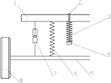
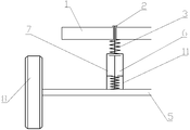
도 1, 도 2, 도 3을 참고하면, 실시예 1의 도면은, 차 프레임(1), 보정 스프링 프리 타이트닝 장치(3), 보정 스프링(3), 진동 격리 블록(4), 가이드 기구(5), 자유 스프링(6), 라이트 댐핑 쇼크업소버(7), 차 휠(8)을 나타낸다. 1, 2, and 3, the drawings of
본 발명에 따른 서스펜션은 차 프레임(1), 보정 스프링 프리 타이트닝 장치(2), 보정 스프링(3), 진동 격리 블록(4), 가이드 기구(5), 자유 스프링(6), 라이트 댐핑 쇼크업소버(7), 차 휠(8)을 포함한다. 그중 탄성소자는 자유 스프링(6)(자유 스프링(6)은 스파이럴 스프링이다)과 보정 스프링(3)(보정 스프링(3)은 스파이럴 스프링이다)의 병렬 조합으로 이루어지고, 차량이 정지되거나 또는 평형상태에 있는 경우, 서스펜션에 발생하는 차 휠의 부하는 자유 스프링(6)과 보정 스프링(3)이 공동 부담하고, 서스펜션의 부하가 보정 구간(보정 구간의 최소치가 A, 최대치가 B, 차량이 무부하인 경우 서스펜션이 받는 하중은 G0, 부하가 있는 경우 서스펜션이 받는 하중을 G로 설정할 경우, A<G0<G<B, 이 수치는 설계한 최소 범위이고, 일반 설계는 모두 이 범위를 초과한다)에 있는 경우, 자유 스프링(6)과 보정 스프링(3)의 길이는 모두 변화가 발생하지 않고, 오직 진동 격리 블록(4)만 일정한 변형이 발생한다. 다시 말하면 부하의 변화에 따라 서스펜션의 행정에 작은 변화만 발생한다. A suspension according to the present invention comprises a
이런 서스펜션에서, 서스펜션을 이룬 보정 스프링의 초기 장력이 F>1.1(G-G0)이고, 자유 스프링이 차량에 제공하는 탄성 지지력은 f<G0이다. In this suspension, and the initial tension of the spring compensation achieved the suspension F> 1.1 (GG 0), and the urging force of the free spring is provided in the vehicle is f <G 0.
서스펜션의 부하는 0.9G0보다 작은 경우, 서스펜션의 자유 스프링(6)은 연신되고, 모든 부하를 감당하고; 보정 스프링(3)의 길이는 변하지 않고 부하를 분담하지 않는다. If the load of the suspension is less than 0.9G 0 , the
서스펜션의 부하가 1.1(G-G0)이 초과 시, 서스펜션의 자유 스프링(6)은 계속 압축되고, 일부분 부하를 감당한다; 보정 스프링(3)은 압축되고, 나머지 부하를 분담한다. When the load of the suspension exceeds 1.1 (GG 0 ), the
이런 기술의 가장 주요한 특징이 바로 보정 스프링(3)의 최대 행정이 프리 타이트닝 장치(2)의 제한을 받고, 단지 서스펜션의 정적 휨에서 동적 비틀림 범위 내에서 작업한다. The most important feature of this technique is that the maximum stroke of the compensating
서스펜션의 정적 휨(6) 부근에서, 만약 서스펜션 무부하는 G0이고, 부하가 있는 경우 받은 부하의 하중은 G이고, 서스펜션의 자유 스프링(6)이 제공하는 지지력(f)과 보정 스프링(3)의 초기 장력(F)은 동시에 아래 관계를 만족시켜야 한다. In the vicinity of the
[수0001] [0001]

다시 말하면, 자유 스프링(6)이 제공하는 지지력은 서스펜션이 받는 정적 부하보다 작고, 또 일부분의 부하는 초기 장력에 의해 한정되는 보정 스프링(3)이 부담하고, 서스펜션의 하중이 상기 요구를 만족 시, 서스펜션 부하의 그 정적 휨 값 부근의 일정 범위 내에 변화가 발생 시, 보정 스프링(3)의 초기 장력의 보정 작용에 의해, 자유 스프링(6)과 보정 스프링(3)의 길이는 모두 변화가 발생하지 않고, 서스펜션 행정은 설령 변화가 발생하더라도, 단지 진동 격리 블록이 압축을 받을 때 발생하는 형변이고, 형변량이 아주 작다 하더라도 전체 효과가 행정 변화가 아주 작은 것이고, 이 부하 범위 내에서 서스펜션의 강도가 아주 높다. 서스펜션의 부하의 변화는 이 범위를 초과하였고, 두 개의 스프링은 상응한 행정 변화를 발생하고, 차량의 주행 조건을 완전히 만족시킬 수 있다. In other words, the bearing force provided by the
합리적인 설계를 통해, 차량의 서스펜딩 부하가 일정 범위 내에서 변화케 할 시, 서스펜션의 행정은 변하지 않거나 단지 아주 작은 변화만 발생하며 이것이 바로 차량 서스펜션이 필요로 하는 특성이다. With reasonable design, when the suspending load of the vehicle changes within a certain range, the stroke of the suspension does not change or only minor changes occur, which is what a vehicle suspension needs.
하나의 휠이 충격을 받을 시, 이 서스펜션은 동시에 충격도 받으며 그 부하의 변화도 차체에 진동 충격을 발생하고, 이 충격은 차 프레임을 통해 기타 서스펜션에 전달되나, 기타 서스펜션 작업이 보정 구간 내에 있으므로 충격이 가져오는 부하의 변화가 만약 기타 서스펜션의 보정 구간 내에 있다면, 기타 서스펜션의 행정은 변화가 발생하지 않거나 변화가 아주 작고, 전체 차체는 여전히 상대적으로 평형의 상태를 유지한다; 동일하게 마약 차량이 속도, 방향 및 하중 변화로 인해 보정 구간 내의 범위 내에서 변화가 발생하는 경우, 서스펜션 부하가 발생하는 변화 또한 서스펜딩 된 보정 스프링(3)에 의해 보정될 수 있고, 서스펜션의 행정은 여전히 필요로 하는 안정 상태를 유지하고, 차량은 양호한 조작성과 안정을 유지할 수 있음과 동시에 차량의 쾌적 성능에 영향을 주지 않는다. When one wheel is impacted, the suspension is shocked at the same time, and the change in load also causes a vibration shock to the car body, which is transmitted to the other suspension through the car frame, but other suspension operations are within the calibration interval If the change in the impact load is within the calibration interval of the other suspension, the stroke of the other suspension does not change or the change is very small and the entire body remains in a relatively equilibrium state; Likewise, when a change occurs in the range of the correction section due to the speed, direction and load change of the drug vehicle, the change in which the suspension load occurs can also be corrected by the suspended
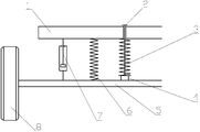
도 4, 도 5, 도 6을 참고하면, 실시예 2에서 보정 스프링(3), 진동 격리 블록(4), 자유 스프링(6), 차 휠(8)이 나타난다. Referring to Figs. 4, 5 and 6, the
실시예 2에서 본 발명의 차량 서스펜션의 탄성 소자도 동일하게 자유 스프링(6)과 보정 스프링(3)을 포함하고, 그중 보정 스프링(3)은 에어 스프링이고, 자유 스프링(6)은 강판 스프링이다. The elastic element of the vehicle suspension of the present invention also includes a
본 실시예에서, 보정 스프링(3)이 일으키는 작용은 실시예 1에 따른 보정 스프링(3)의 것과 동일하고, 강판 스프링이 일으키는 작용은 실시예 1에 따른 자유 스프링(6)의 것과 동일하다. 다른 점은 에어 스프링 자체가 프리 타이트닝 스프링의 특성이 있어 별도로 프리 타이트닝 장치를 별도로 증가할 필요가 없고, 강판 스프링은 동시에 가이드 연결 작용을 일으킬 수 있고, 서스펜션의 구조는 더욱 간소화된 설계를 사용할 수 있으며 동시에 에어 스프링의 진동 격리 성능은 이미 아주 좋으며, 추가된 진동 격리 블록(4)은 소음을 추가로 줄일 수 있으며, 강판 스프링 자체는 이미 일정한 진동 감소 작용을 구비한다. 만약 진동 감소에 대한 요구가 높지 않으면 쇼크업소버의 설계를 취소할 수 있다. 이와 같은 서스펜션은 그것을 구성하는 에어 스프링의 초기 장력은 F>1.1(G-G0)이고, 자유 스프링은 차량이 제공하는 탄성 지지력은 f<G0이다. In this embodiment, the action of the
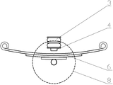
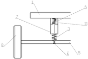
도 7, 도 8, 도 9를 참고하면, 실시예 3에서, 자유 스프링(6), 라이트 댐핑 쇼크업소버(7), 가이드 실린더(11), 보정 스프링(3), 차 휠(8)을 나타낸다.7, 8, and 9, the
실시예 3에서, 본 발명의 차량 서스펜션의 탄성소자도 동일하게 자유 스프링(6)과 보정 스프링(3)을 포함하고, 그중 보정 스프링(3)은 스파이럴 스프링이고, 자유 스프링(6)은 스파이럴 스프링이다. In the third embodiment, the elastic elements of the vehicle suspension of the present invention also include a
본 실시예에서, 보정 스프링(3)이 일으키는 작용은 실시예 1에 따른 보정 스프링(3)의 것과 동일하고, 자유 스프링(6)이 일으키는 작용은 실시예 1에 따른 자유 스프링(6)의 것과 동일하다. 다른 점은 본 실시예에서, 보정 스프링(3)과 자유 스프링(6)은 직렬 연결되고, 라이트 댐핑 쇼크업소버(7) 상에 자유 스프링(6)의 가이드 실린더(11)가 연결되어 있고, 스프링 가이드 작용을 일으킬 뿐만 아니라 자유 스프링(6)이 제공하는 탄성 지지력이 f<G0을 만족하도록 한정할 수도 있고, 동시에 설계는 보정 스프링(3)의 초기 장력이 F>G이게 한다.In this embodiment, the action of the
서스펜션의 정적 휨 부근에서, 만약 서스펜션의 무부하는 G0이고, 부하가 있는 경우, 서스펜션이 받는 부하는 G이고, 서스펜션의 자유 스프링(6)이 제공하는 지지력(f)과 보정 스프링(3)의 초기 장력(F)의 관계는 아래와 같다: In the vicinity of the static deflection of the suspension, if a no-load of the suspension is G 0, if the load, suspension of receiving the load G, and the supporting force to free the
[수0002] [0002]

이와 같은 서스펜션에서, 차량의 조작성을 증가시키기 위하여, 통상 서스펜션을 이루는 보정 스프링(3)의 초기 장력이 F>1.1G이고, 자유 스프링(6)은 차량에서 제공되는 탄성 지지력이 f<0.9G0이다. In such a suspension, in order to increase the maneuverability of the vehicle, and the initial tension F> 1.1G the compensation spring (3) forming the conventional suspension,
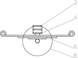
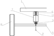
도 10, 도 11, 도 12를 참고하면, 실시예 4에서, 자유 스프링(6), 라이트 댐핑 쇼크업소버(7), 가이드 실린더(11), 보정 스프링(3), 차 휠(8)을 나타낸다. 10, 11, and 12, the
실시예 4에서, 본 발명의 차량의 서스펜션의 탄성 소자는 자유 스프링(6)과 보정 스프링(3)을 동일하게 포함하고, 그중 보정 스프링(3)은 스파이럴 스프링(3)이고, 자유 스프링(6)은 스파이럴 스프링(6)이다. In the fourth embodiment, the elastic elements of the suspension of the vehicle of the present invention include the
본 실시예에서 보정 스프링(3)이 일으키는 작용은 실시예 3에 따른 보정 스프링(3)과 동일하며, 자유 스프링(6)이 일으키는 작용은 실시예 3에 따른 자유 스프링(6)과 동일하다. 다른 것은 본 실시예에서, 보정 스프링(3)이 아래에 있고, 자유 스프링(6)이 위에 있으며 라이트 댐핑 쇼크업소버(7) 상에 자유 스프링(6)의 가이드 실린더(11)가 연결되어 있고, 스프링 가이드 작용을 일으킬 뿐만 아니라 자유 스프링(6)이 제공하는 탄성 지지력이 f<G0을 만족하도록 한정할 수도 있고, 동시에 설계는 보정 스프링(3)의 초기 장력이 F>G이게 한다. The action of the
구체적인 구조는, 자유 스프링(6) 상단은 차 프레임(1)에 연결되고, 하단은 라이트 댐핑 쇼크업소버(7) 상단에 연결되고, 라이트 댐핑 쇼크업소버(7) 외벽 상단은 가이드 실린더(11)가 연결되어 있고; 상기 보정 스프링(3) 상단은 라이트 댐핑 쇼크업소버(7) 하단에 연결되고, 상기 보정 스프링(3) 하단은 가이드 기구(5)에 연결되고, 연결단에 보정 스프링 프리 타이트닝 장치(2)가 설치되어 있고, 상기 자유 스프링(6), 라이트 댐핑 쇼크업소버(7), 보정 스프링(3)은 차례대로 차 프레임(1)과 가이드 기구(5) 사이에 직렬연결로 설치된다. The upper end of the
상기 설명과 실시예를 종합하면, 본 발명에 따른 차량 서스펜션 설계 방법과 구조는 종래의 차량 서스펜션 장치와 다르며, 이런 서스펜션 장치는 2개 이상의 탄성 소자의 조합 및 보정을 서스펜딩하는 것에 의거하여 차량의 복수의 서스펜션의 상호 자동 보정 특성을 실현하였고, 서스펜션의 조작성과 쾌적성 조건을 만족시키기 위하여 새로운 설계 방법을 제공하였다. [0030] Taking the above description and examples together, the method and structure of a vehicle suspension design according to the present invention is different from that of a conventional vehicle suspension device, and such a suspension device is capable of suppressing the collision and correction of two or more elastic elements, And a new design method was provided to satisfy the operability and comfort conditions of the suspension.
이상의 실시예는 단지 본 발명의 설계 원리에 대해 예를 들어 설명한 것이고, 실제 설계와 구조는 더욱 많은 변화가 있을 수 있는데, 예를 들면 보정 구간의 범위는 A<G0<G<B을 만족시켜야 할 뿐만 아니라 B-A가 (G-G0)50% 이상을 초과하는 설계도 있고, 특종 차량에 대해서 심지어 한 배 초과할 수 있으며 또한 부하의 크기를 검측하고, 보정 구간에 대한 설계를 통해 단일 서스펜션이 차체에 일으키는 영향에 대해 기타 서스펜션을 통해 보정 및 수정할 수 있고, 최종 차체의 진동을 유지 및 줄일 수 있으며 동시에 조작성과 쾌적성을 향상시킬 수 있다. Or more embodiments only will described, for example, the design principles of the present invention, the actual design and construction may be more changes, for example, the range of the calibration interval must satisfy A <G 0 <G <B There is also a design in which BA is more than 50% (GG 0 ), it can be even more than one time for special vehicles and also the size of the load is detected, and the design for the compensation interval causes a single suspension The influence can be corrected and corrected through other suspensions, the vibration of the final body can be maintained and reduced, and the operability and comfort can be improved at the same time.
이런 설계와 장치는 모두 보정 스프링에 대한 프리 타이트닝을 통해 실현되고, 스프링의 프리 타이트닝을 통해 서스펜션의 자동 보정 기능을 실현하는 설계와 구조는 모두 이 특허 보호 범위 내에 있다. All of these designs and devices are realized through pre-tightening of the compensating springs, and the design and construction to realize the automatic compensation of the suspension through pre-tightening of the springs are within the scope of this patent protection.
이렇게 설계된 서스펜션은 한 편으로 기하적 변형 능력이 좋으며, 도로면의 충격을 흡수하는 능력을 구비하여 차체의 진동을 효과적으로 줄이거나 방지한다; 다른 한편, 서스펜션이 정적 휨에 도달한 경우, 서스펜션의 부하에 대해 자동 보정 기능을 구비하여, 차량이 속도, 방향 및 적재에 변화가 발생하는 경우, 서스펜션 행정의 과도한 변화를 효과적으로 줄이거나 방지할 수 있고, 차량의 탑승 쾌적성과 운전 안전성의 모순을 효과적으로 해결하였고, 일반 차량의 전자 제어 액티브 서스펜션에 상당하거나 그것을 초과하는 사용효과를 갖는다. The suspension thus designed has a good geometrically deformable ability on one side and has the ability to absorb impact on the road surface, effectively reducing or preventing vibration of the vehicle body; On the other hand, when the suspension reaches a static bend, it is equipped with an automatic correction function for the load of the suspension, so that when the vehicle changes in speed, direction and load, it is possible to effectively reduce or prevent an excessive change in the suspension stroke , Effectively solving the inconsistency of the ride comfort of the vehicle and the driving safety, and has the effect of using or exceeding the electronic control active suspension of the general vehicle.
위의 내용은 본 발명의 가장 바람직한 실시예 및 그것이 운용한 기술원리이고 해당 분야의 기술자에게 있어, 본 발명의 정신과 범위를 벗어나지 않는 상황에서, 본 발명 기술방안을 기초로 하는 동등 효과의 변환, 간단한 대체 등은 자명한 변경이며 모두 본 발명의 범위 내에 속한다. It is to be understood that both the foregoing general description and the following detailed description of the present invention are exemplary and explanatory and are intended to provide further explanation of the invention as claimed. Substitutions, etc. are self-evident and all fall within the scope of the invention.
Claims (10)
그것은 자유 스프링, 보정 스프링, 보정 스프링 프리 타이트닝 장치(2), 라이트 댐핑 쇼크업소버(7) 및 가이드 기구(5)를 포함하고;
상기 자유 스프링, 보정 스프링, 라이트 댐핑 쇼크업소버는 차 프레임(1)과 가이드 기구(5) 사이에 설치되고, 상기 보정 스프링은 차 프레임(1) 또는 가이드 기구(5)에 연결되고, 보정 스프링 일단에 보정 스프링 프리 타이트닝 장치(2)가 설치되어 있고, 가이드 기구(5)는 차 휠과 차 바디를 연결하고, 자유 스프링(6), 보정 스프링(3) 및 라이트 댐핑 쇼크업소버(7)를 위해 위치 고정 설치를 제공하는 것을 특징으로 하는 조합 스프링 보정 서스펜션 장치. A combined spring compensating suspension device comprising:
It comprises a free spring, a compensating spring, a compensating spring pre-tightening device (2), a light damping shock absorber (7) and a guide mechanism (5);
The free spring, the correction spring, and the light damping shock absorber are installed between the car frame 1 and the guide mechanism 5, and the correction spring is connected to the car frame 1 or the guide mechanism 5, The guide mechanism 5 connects the car wheel and the car body and is provided with a free spring 6, a correction spring 3 and a light damping shock absorber 7 And wherein the positioning means provides a fixed position mounting.
상기 자유 스프링(6) 상단은 차 프레임(1)에 연결되고, 하단은 가이드 기구(5)에 연결되고, 상기 라이트 댐핑 쇼크업소버(7) 상단은 차 프레임(1)에 연결되고, 하단은 가이드 기구(5)에 연결되고; 상기 보정 스프링(3) 상단은 차 프레임(1)에 연결되거나 하단이 가이드 기구(5)에 고정 연결되고, 연결단에 보정 스프링 프리 타이트닝 장치(2)가 장착되어 있고, 상기 보정 스프링(3) 하단 또는 상단은 진동 격리 블록이 장착되어 있고; 상기 라이트 댐핑 쇼크업소버(7), 자유 스프링(6) 및 보정 스프링(3)은 차 프레임(2)과 가이드 기구(5) 사이에 병렬로 장착되는 것을 특징으로 조합 스프링 보정 서스펜션 장치.The method according to claim 1,
The upper end of the free spring 6 is connected to the car frame 1 and the lower end thereof is connected to the guide mechanism 5. The upper end of the light damping shock absorber 7 is connected to the car frame 1, Connected to a mechanism (5); The upper end of the correction spring 3 is connected to the car frame 1 or the lower end thereof is fixedly connected to the guide mechanism 5. The correction spring pre-tightening device 2 is mounted on the connection end, The bottom or top is equipped with a vibration isolation block; Characterized in that the light damping shock absorber (7), free spring (6) and correction spring (3) are mounted in parallel between the car frame (2) and the guide mechanism (5).
상기 자유 스프링(6) 하단은 가이드 기구(5)에 연결되고, 상단은 라이트 댐핑 쇼크업소버(7) 하단에 연결되고, 라이트 댐핑 쇼크업소버(7) 외벽 하단에 가이드 실린더(11)가 연결되어 있고; 상기 보정 스프링(3) 하단은 라이트 댐핑 쇼크업소버 상단에 연결되고,
상기 보정 스프링(3) 상단은 차 프레임(1)에 연결되고, 연결단에 보정 스프링 프리 타이트닝 장치(2)가 장착되어 있고, 상기 보정 스프링(3), 라이트 댐핑 쇼크업소버(7), 자유 스프링(6)은 차례대로 차 프레임(1)과 가이드 기구(5) 사이에 직렬 연결로 장착되는 것을 특징으로 하는 조합 스프링 보정 서스펜션 장치.The method according to claim 1,
The lower end of the free spring 6 is connected to the guide mechanism 5 and the upper end thereof is connected to the lower end of the light damping shock absorber 7 and the guide cylinder 11 is connected to the lower end of the outer wall of the light damping shock absorber 7 ; The lower end of the correction spring 3 is connected to the upper end of the light damping shock absorber,
The upper end of the correction spring 3 is connected to the car frame 1 and the correction spring pre-tightening device 2 is mounted on the connection end. The correction spring 3, the light damping shock absorber 7, (6) are successively mounted in series between the car frame (1) and the guide mechanism (5).
상기 자유 스프링(6) 상단은 차 프레임(1) 에 연결되고, 하단은 라이트 댐핑 쇼크업소버(7) 상단에 연결되고, 라이트 댐핑 쇼크업소버(7) 외벽 상단에 가이드 실린더(11)가 연결되어 있고; 상기 보정 스프링(3) 상단은 라이트 댐핑 쇼크업소버 하단에 연결되고,
상기 보정 스프링(3) 하단은 가이드 기구(5)에 연결되고, 연결단에 보정 스프링 프리 타이트닝 장치(2)가 장착되어 있고, 상기 자유 스프링(6), 라이트 댐핑 쇼크업소버(7), 보정 스프링(3)은 차례대로 차 프레임(1)과 가이드 기구(5) 사이에 직렬로 장착되는 것을 특징으로 하는 조합 스프링 보정 서스펜션 장치.The method according to claim 1,
The upper end of the free spring 6 is connected to the car frame 1 and the lower end is connected to the upper end of the light damping shock absorber 7 and the guide cylinder 11 is connected to the upper end of the outer wall of the light damping shock absorber 7 ; The upper end of the compensation spring 3 is connected to the lower end of the light damping shock absorber,
The lower end of the correction spring 3 is connected to the guide mechanism 5 and the correction spring pre-tightening device 2 is mounted on the connection end. The free spring 6, the light damping shock absorber 7, (3) are mounted in series between the car frame (1) and the guide mechanism (5) in order.
상기 자유 스프링(6)의 중심 하단은 가이드 기구(5)에 연결되고, 양측 상단은 차 프레임(1)에 연결되고, 상기 보정 스프링(3) 상단은 차 프레임(1)에 연결되고, 상기 보정 스프링(3) 하단은 진동 격리 블록(4)이 장착되어 있고, 상기 진동 격리 블록(4)과 자유 스프링(6)은 중심을 맞추어 배치되는 것을 특징으로 하는 조합 스프링 보정 서스펜션 장치.The method according to claim 1,
The lower end of the center of the free spring 6 is connected to the guide mechanism 5 and the upper ends of the free springs 6 are connected to the car frame 1. The upper end of the correction spring 3 is connected to the car frame 1, Characterized in that the vibration isolating block (4) is mounted on the lower end of the spring (3), and the vibration isolation block (4) and the free spring (6) are centered.
자유 스프링(6)과 보정 스프링(3)은 병렬로 장착 시, 차량이 무부하인 경우, 서스펜션이 감당하는 하중은 G0이고, 적재하였을 시 서스펜션이 감당하는 하중은 G이고, 서스펜션을 이루는 보정 스프링(3)의 초기 장력은 F>G-G0이고, 자유 스프링(6)이 차량의 정적 휨 값 부근에 있는 경우, 차량이 제공하는 탄성 지지력이 f<G0인 것을 특징으로 하는 조합 스프링 보정 서스펜션 장치.3. The method of claim 2,
When the free spring 6 and the compensation spring 3 are mounted in parallel, when the vehicle is unloaded, the load to be subjected to the suspension is G 0 , the load to be subjected to the suspension is G when the vehicle is loaded, the initial tension of the (3) is f> and GG 0, the free spring 6 combined spring compensation suspension system, characterized in that in this case in the vicinity of the static deflection value of the vehicle, the urging force of the vehicle is provided with a f <G 0 .
자유 스프링(6)과 보정 스프링(3)이 직렬로 장착될 시, 차량이 무부하인 경우 서스펜션이 받는 하중은 G0이고, 적재 시 서스펜션이 받는 하중은 G이고, 서스펜션을 이루는 보정 스프링(3)의 초기 장력은 F>G이고, 자유 스프링(6)은 차량의 정적 휨 값 부근에 있는 경우, 차량이 제공하는 탄성 지지력은 f<G0을 만족시키는 것을 특징으로 하는 조합 스프링 보정 서스펜션 장치. The method according to claim 3 or 4,
When the free spring 6 and the correction spring 3 are mounted in series, the load received by the suspension when the vehicle is unloaded is G 0 , the load received by the suspension is G, the correction spring 3, the initial tension of the f> G, and the free spring 6 is combined suspension spring compensation device, characterized in that to satisfy the static deflection when in the vicinity of the value, the urging force of the vehicle is provided is f <G 0 of the vehicle.
서스펜션을 이루는 보정 스프링(3)의 초기 장력은 F>1.1(G-G0)이고, 자유 스프링(6)이 차량의 정적 휨 값 부근에 있는 경우, 차량이 제공하는 탄성 지지력은 f<0.9G0인 것을 특징으로 하는 조합 스프링 보정 서스펜션 장치. The method according to claim 6,
The initial tension of the compensation spring (3) forming the suspension is F> 1.1 (GG 0), and the free spring 6 in this case in the vicinity of the static deflection value of the vehicle, the urging force of the vehicle is provided is f <0 is 0.9G Wherein the suspension spring is a spring.
서스펜션을 이루는 보정 스프링(3)의 초기 장력은 F>1.1G이고, 자유 스프링(6)이 차량의 정적 휨 값 부근에 있는 경우, 차량이 제공하는 탄성 지지력은 f<0.9G0인 것을 특징으로 하는 조합 스프링 보정 서스펜션 장치. 8. The method of claim 7,
If the initial tension of the compensation spring (3) forming the suspension is F> 1.1G, and the free spring 6 is in the vicinity of the static deflection value of the vehicle, the urging force of the vehicle is provided is characterized in that f <0.9G 0 A combination spring correction suspension device.
상기 라이트 댐핑 쇼크업소버의 댐핑 계수는 신축 행정이 0.25보다 작고, 압축 행정이 0.15보다 작은 것을 특징으로 하는 조합 스프링 보정 서스펜션 장치. The method according to claim 5 or 6,
Wherein the damping coefficient of the light damping shock absorber is smaller than 0.25 in the expansion stroke and smaller than 0.15 in the compression stroke.
Applications Claiming Priority (3)
| Application Number | Priority Date | Filing Date | Title |
|---|---|---|---|
| CN201510206214.9 | 2015-04-27 | ||
| CN201510206214.9A CN104773045B (en) | 2015-04-27 | 2015-04-27 | Cluster spring compensates suspension arrangement |
| PCT/CN2016/078637 WO2016173390A1 (en) | 2015-04-27 | 2016-04-07 | Combined spring compensation suspension device |
Publications (1)
| Publication Number | Publication Date |
|---|---|
| KR20170140286A true KR20170140286A (en) | 2017-12-20 |
Family
ID=53614942
Family Applications (1)
| Application Number | Title | Priority Date | Filing Date |
|---|---|---|---|
| KR1020177033338A KR20170140286A (en) | 2015-04-27 | 2016-04-07 | Combination Spring Compensation Suspension System |
Country Status (6)
| Country | Link |
|---|---|
| US (1) | US20180022178A1 (en) |
| EP (1) | EP3290244A4 (en) |
| JP (1) | JP2018514440A (en) |
| KR (1) | KR20170140286A (en) |
| CN (1) | CN104773045B (en) |
| WO (1) | WO2016173390A1 (en) |
Families Citing this family (22)
| Publication number | Priority date | Publication date | Assignee | Title |
|---|---|---|---|---|
| US10300760B1 (en) | 2015-03-18 | 2019-05-28 | Apple Inc. | Fully-actuated suspension system |
| CN104773045B (en) * | 2015-04-27 | 2017-11-14 | 席玉林 | Cluster spring compensates suspension arrangement |
| CN106476867B (en) * | 2016-10-27 | 2019-08-30 | 台州宝诚科技服务有限公司 | Novel logistics trolley |
| CN106844903B (en) * | 2017-01-03 | 2020-02-28 | 山东理工大学 | Simulation calculation method for deflection characteristic of non-equal-frequency-bias one-level gradient-stiffness plate spring |
| WO2018208510A1 (en) | 2017-05-08 | 2018-11-15 | Segame Technologies Llc | Active suspension system |
| US10899340B1 (en) | 2017-06-21 | 2021-01-26 | Apple Inc. | Vehicle with automated subsystems |
| US11173766B1 (en) | 2017-09-07 | 2021-11-16 | Apple Inc. | Suspension system with locking structure |
| US10906370B1 (en) | 2017-09-15 | 2021-02-02 | Apple Inc. | Active suspension system |
| US11124035B1 (en) | 2017-09-25 | 2021-09-21 | Apple Inc. | Multi-stage active suspension actuator |
| US10960723B1 (en) | 2017-09-26 | 2021-03-30 | Apple Inc. | Wheel-mounted suspension actuators |
| CN108608822B (en) * | 2018-07-23 | 2023-12-08 | 浙江大学滨海产业技术研究院 | AGV suspension system elasticity adjusting method and system |
| US11285773B1 (en) | 2018-09-12 | 2022-03-29 | Apple Inc. | Control system |
| US11634167B1 (en) | 2018-09-14 | 2023-04-25 | Apple Inc. | Transmitting axial and rotational movement to a hub |
| US11345209B1 (en) * | 2019-06-03 | 2022-05-31 | Apple Inc. | Suspension systems |
| US11938922B1 (en) | 2019-09-23 | 2024-03-26 | Apple Inc. | Motion control system |
| US11179991B1 (en) | 2019-09-23 | 2021-11-23 | Apple Inc. | Suspension systems |
| CN110978926B (en) * | 2019-12-31 | 2024-02-23 | 杭州极木科技有限公司 | Multistage non-independent suspension system |
| CN113059972A (en) * | 2020-01-02 | 2021-07-02 | 株洲时代新材料科技股份有限公司 | Lightweight suspension device |
| US11707961B1 (en) | 2020-04-28 | 2023-07-25 | Apple Inc. | Actuator with reinforcing structure for torsion resistance |
| US11828339B1 (en) | 2020-07-07 | 2023-11-28 | Apple Inc. | Vibration control system |
| CN112319169B (en) * | 2020-10-19 | 2022-02-25 | 江苏大学 | Top layer car body attitude control method based on pitching lateral force compensation |
| CN114408056A (en) * | 2021-12-30 | 2022-04-29 | 上海龙创汽车设计股份有限公司 | Multifunctional service robot chassis |
Family Cites Families (52)
| Publication number | Priority date | Publication date | Assignee | Title |
|---|---|---|---|---|
| US887002A (en) * | 1908-05-05 | James E Marriner | Cushion attachment for automobiles. | |
| GB190928954A (en) * | 1909-12-10 | 1910-06-09 | John Edward Anger | Improvements in or relating to Bearing Springs or Spring Bearing Devices for Road Vehicles. |
| BE369139A (en) * | 1929-04-11 | |||
| FR767306A (en) * | 1933-02-04 | 1934-07-16 | Daimler Benz Ag | Spring shock absorber with additional springs |
| US2902274A (en) * | 1957-06-11 | 1959-09-01 | Monroe Auto Equipment Co | Vehicle suspension system |
| GB1145419A (en) * | 1967-03-07 | 1969-03-12 | Daimler Benz Ag | Improvements relating to axle suspensions for vehicles |
| US3559976A (en) * | 1968-10-17 | 1971-02-02 | Joseph Jerz Jr | Variable stiffness suspension system |
| AU522455B2 (en) * | 1977-10-12 | 1982-06-10 | Leonard Jefferson Blee | Servo controlled vehicle suspension |
| FR2506014B1 (en) * | 1981-05-14 | 1987-08-21 | Brisard Gerard | ON-BOARD APPARATUS FOR CONTROLLING SUSPENSION SHOCK ABSORBERS |
| FR2593256A1 (en) * | 1986-01-22 | 1987-07-24 | Vey Maurice | Damper for motor vehicle suspension |
| DE3608934A1 (en) * | 1986-03-18 | 1987-09-24 | Fichtel & Sachs Ag | Suspension system for a motor vehicle |
| DE3739663A1 (en) * | 1987-11-24 | 1989-06-08 | Bayerische Motoren Werke Ag | Adjustable shock-absorbing leg for motor vehicles |
| US4921272A (en) * | 1989-02-10 | 1990-05-01 | Lord Corporation | Semi-active damper valve means with electromagnetically movable discs in the piston |
| FR2654992B1 (en) * | 1989-11-28 | 1992-03-06 | Renault | VEHICLE SUSPENSION. |
| DE4104904A1 (en) * | 1991-02-18 | 1992-08-20 | Bilstein August Gmbh Co Kg | ADJUSTABLE SUSPENSION SYSTEM FOR WHEEL SUSPENSIONS ON MOTOR VEHICLES |
| FR2677929A1 (en) * | 1991-06-24 | 1992-12-24 | Bianchi Mauro Sa | SUSPENSION METHOD FOR VEHICLES USING TWO RAIDERS, RESPECTIVELY DESIGNED FOR A GOOD LEVEL OF COMFORT AND A BEAUTIFUL LEVEL OF BEHAVIOR. |
| US5685555A (en) * | 1995-02-21 | 1997-11-11 | The Raymond Corporation | Lift truck with inertial damper |
| US5785345A (en) * | 1995-10-16 | 1998-07-28 | The Boler Company | Means for and method of controlling frame rise in vehicle suspensions |
| JP3657039B2 (en) * | 1995-10-30 | 2005-06-08 | カヤバ工業株式会社 | Suspension mechanism |
| FR2757107B1 (en) * | 1996-12-12 | 1999-03-12 | Bianchi Mauro Sa | VEHICLE WHEEL SUSPENSIONS USING A SPRING COMBINED WITH A SOFT REINFORCEMENT INTENDED TO MODIFY ITS STIFFNESS CURVE |
| DE19855310C2 (en) * | 1998-12-01 | 2000-10-05 | Daimler Chrysler Ag | Active suspension system for vehicles |
| US20020038929A1 (en) * | 2000-06-23 | 2002-04-04 | Now Leo Martin | Shock absorber |
| US6761372B2 (en) * | 2001-03-09 | 2004-07-13 | Peter E Bryant | Opposing spring resilient tension suspension system |
| US20030080527A1 (en) * | 2001-10-26 | 2003-05-01 | Bryant Peter E. | Opposing spring rebound tension suspension system |
| DE10244361A1 (en) * | 2002-09-24 | 2004-04-01 | Daimlerchrysler Ag | Device for vibration damping in a vehicle |
| CN2705384Y (en) * | 2004-04-23 | 2005-06-22 | 中国嘉陵工业股份有限公司(集团) | Motorcycle inner tube changing rigidity front shock absorber |
| US7665585B2 (en) * | 2004-09-03 | 2010-02-23 | Alexandridis Alexander A | Vehicle suspension system and method for operating |
| JP4464798B2 (en) * | 2004-11-24 | 2010-05-19 | トヨタ自動車株式会社 | Vehicle suspension system |
| DE102004058698B3 (en) * | 2004-12-06 | 2006-02-09 | Muhr Und Bender Kg | Adjustable spring wheel suspension for motor vehicle has coil spring arranged with force direction line deviating from geometrical center line of spring |
| DE202005006337U1 (en) * | 2005-04-21 | 2005-06-16 | Goldschmitt Techmobil Ag | Towing vehicle with axle suspension has spring unit with spring leaf element connected to axle and fastened by both ends on frame of vehicle, and air spring element installed between frame and axle |
| JP4396611B2 (en) * | 2005-10-07 | 2010-01-13 | トヨタ自動車株式会社 | Suspension cylinder device for vehicle |
| US7681898B2 (en) * | 2005-11-18 | 2010-03-23 | Tlc Suspensions, Llc | Composite suspension system for a vehicle |
| DE102006011856A1 (en) * | 2006-03-15 | 2007-09-20 | Bayerische Motoren Werke Ag | Suspension system for a vehicle suspension |
| JP4500786B2 (en) * | 2006-04-27 | 2010-07-14 | カヤバ工業株式会社 | Shock absorber |
| US7850195B2 (en) * | 2006-05-25 | 2010-12-14 | Simard Suspensions Inc. | Tandem suspension for steerable axles |
| DE102007042206B4 (en) * | 2007-09-05 | 2016-05-25 | Bayerische Motoren Werke Aktiengesellschaft | Active chassis system of a two-lane vehicle |
| DE102007051971B4 (en) * | 2007-10-31 | 2010-09-16 | Audi Ag | Adjustment device for suspension devices |
| US7962261B2 (en) * | 2007-11-12 | 2011-06-14 | Bose Corporation | Vehicle suspension |
| JP4930411B2 (en) * | 2008-02-26 | 2012-05-16 | トヨタ自動車株式会社 | Vehicle suspension system |
| WO2010079823A1 (en) * | 2009-01-09 | 2010-07-15 | 日本電気株式会社 | Semiconductor device |
| DE102009014201A1 (en) * | 2009-03-20 | 2010-09-23 | Audi Ag | Active electromechanical suspension system for a chassis of a motor vehicle |
| JP5424751B2 (en) * | 2009-07-10 | 2014-02-26 | カヤバ工業株式会社 | Suspension device |
| DE102009051469A1 (en) * | 2009-10-30 | 2011-05-05 | Audi Ag | Suspension for motor vehicles |
| CN201961398U (en) * | 2011-01-25 | 2011-09-07 | 三一重工股份有限公司 | Front suspension device with variable rigidity |
| DE102013002704A1 (en) * | 2013-02-16 | 2014-08-21 | Audi Ag | Torsion bar system for a vehicle axle of a two-lane vehicle |
| DE102013002713B4 (en) * | 2013-02-16 | 2014-08-28 | Audi Ag | A torsion bar spring arrangement for a wheel suspension of a motor vehicle |
| DE102013002714B4 (en) * | 2013-02-16 | 2016-06-30 | Audi Ag | Torsion spring arrangement for a wheel suspension of a motor vehicle |
| US20150231942A1 (en) * | 2014-02-15 | 2015-08-20 | GM Global Technology Operations LLC | Method and apparatus for suspension damping |
| CN203832186U (en) * | 2014-05-04 | 2014-09-17 | 江西远成汽车技术股份有限公司 | Composite suspension system of semitrailer |
| CN204674327U (en) * | 2015-04-27 | 2015-09-30 | 席玉林 | Cluster spring compensates suspension gear |
| CN104773045B (en) * | 2015-04-27 | 2017-11-14 | 席玉林 | Cluster spring compensates suspension arrangement |
| JP6347248B2 (en) * | 2015-10-07 | 2018-06-27 | トヨタ自動車株式会社 | Suspension control device for vehicle |
-
2015
- 2015-04-27 CN CN201510206214.9A patent/CN104773045B/en active Active
-
2016
- 2016-04-07 WO PCT/CN2016/078637 patent/WO2016173390A1/en unknown
- 2016-04-07 EP EP16785821.6A patent/EP3290244A4/en not_active Withdrawn
- 2016-04-07 KR KR1020177033338A patent/KR20170140286A/en unknown
- 2016-04-07 JP JP2017556229A patent/JP2018514440A/en not_active Withdrawn
-
2017
- 2017-09-30 US US15/721,818 patent/US20180022178A1/en not_active Abandoned
Also Published As
| Publication number | Publication date |
|---|---|
| CN104773045A (en) | 2015-07-15 |
| EP3290244A1 (en) | 2018-03-07 |
| JP2018514440A (en) | 2018-06-07 |
| US20180022178A1 (en) | 2018-01-25 |
| CN104773045B (en) | 2017-11-14 |
| WO2016173390A1 (en) | 2016-11-03 |
| EP3290244A4 (en) | 2019-01-02 |
Similar Documents
| Publication | Publication Date | Title |
|---|---|---|
| KR20170140286A (en) | Combination Spring Compensation Suspension System | |
| US8632078B2 (en) | Vehicle with a leaf spring element for the spring suspension of the vehicle | |
| KR100503272B1 (en) | Vehicle suspension | |
| US6830256B2 (en) | Method and apparatus for rebound control | |
| EP2577089B1 (en) | Preloaded dual-spring assembly | |
| EP0000287A1 (en) | A hydro-pneumatic spring suspension strut for motor vehicles | |
| WO2019015604A1 (en) | Dual-spring damper assembly | |
| US6725957B2 (en) | Truck cab suspension with lateral locating wheel | |
| CN204674327U (en) | Cluster spring compensates suspension gear | |
| GB2514258A (en) | Leaf spring assembly for a vehicle | |
| KR100599477B1 (en) | Upper spring seat installation structure for a shock absorber in a vehicle | |
| KR100616010B1 (en) | Strut assembly for automobile | |
| US11548336B1 (en) | Suspension system having rebound control for a vehicle | |
| KR102638576B1 (en) | A variable suspension for mobility using twisted strings | |
| KR100440323B1 (en) | Sealing structure of shocl absorber in vehicle | |
| KR100507122B1 (en) | APPARATUS FOR DECREASING STRUT FRICTION OF McPHERSON STRUT TYPE SUSPENSION | |
| JPS6127289Y2 (en) | ||
| KR100422553B1 (en) | Upper portion mounting structure of suspension in vehicle | |
| KR100243614B1 (en) | Damping device for leaf spring | |
| JPH09300933A (en) | Vehicle suspension system | |
| KR20040006905A (en) | Suspension for vehicles | |
| JPS5963277A (en) | Cab suspension device | |
| KR20050041020A (en) | Roll control device in vehicle | |
| KR19980044919U (en) | Bumper Stopper Structure |