KR20170109665A - Method for producing oriented electromagnetic steel sheet - Google Patents
Method for producing oriented electromagnetic steel sheet Download PDFInfo
- Publication number
- KR20170109665A KR20170109665A KR1020177024601A KR20177024601A KR20170109665A KR 20170109665 A KR20170109665 A KR 20170109665A KR 1020177024601 A KR1020177024601 A KR 1020177024601A KR 20177024601 A KR20177024601 A KR 20177024601A KR 20170109665 A KR20170109665 A KR 20170109665A
- Authority
- KR
- South Korea
- Prior art keywords
- steel sheet
- resist
- mask
- exposure
- annealing
- Prior art date
Links
Images


Classifications
-
- C—CHEMISTRY; METALLURGY
- C21—METALLURGY OF IRON
- C21D—MODIFYING THE PHYSICAL STRUCTURE OF FERROUS METALS; GENERAL DEVICES FOR HEAT TREATMENT OF FERROUS OR NON-FERROUS METALS OR ALLOYS; MAKING METAL MALLEABLE, e.g. BY DECARBURISATION OR TEMPERING
- C21D8/00—Modifying the physical properties by deformation combined with, or followed by, heat treatment
- C21D8/12—Modifying the physical properties by deformation combined with, or followed by, heat treatment during manufacturing of articles with special electromagnetic properties
- C21D8/1294—Modifying the physical properties by deformation combined with, or followed by, heat treatment during manufacturing of articles with special electromagnetic properties involving a localized treatment
-
- C—CHEMISTRY; METALLURGY
- C25—ELECTROLYTIC OR ELECTROPHORETIC PROCESSES; APPARATUS THEREFOR
- C25F—PROCESSES FOR THE ELECTROLYTIC REMOVAL OF MATERIALS FROM OBJECTS; APPARATUS THEREFOR
- C25F3/00—Electrolytic etching or polishing
- C25F3/02—Etching
- C25F3/06—Etching of iron or steel
-
- C—CHEMISTRY; METALLURGY
- C21—METALLURGY OF IRON
- C21D—MODIFYING THE PHYSICAL STRUCTURE OF FERROUS METALS; GENERAL DEVICES FOR HEAT TREATMENT OF FERROUS OR NON-FERROUS METALS OR ALLOYS; MAKING METAL MALLEABLE, e.g. BY DECARBURISATION OR TEMPERING
- C21D6/00—Heat treatment of ferrous alloys
- C21D6/005—Heat treatment of ferrous alloys containing Mn
-
- C—CHEMISTRY; METALLURGY
- C21—METALLURGY OF IRON
- C21D—MODIFYING THE PHYSICAL STRUCTURE OF FERROUS METALS; GENERAL DEVICES FOR HEAT TREATMENT OF FERROUS OR NON-FERROUS METALS OR ALLOYS; MAKING METAL MALLEABLE, e.g. BY DECARBURISATION OR TEMPERING
- C21D6/00—Heat treatment of ferrous alloys
- C21D6/008—Heat treatment of ferrous alloys containing Si
-
- C—CHEMISTRY; METALLURGY
- C21—METALLURGY OF IRON
- C21D—MODIFYING THE PHYSICAL STRUCTURE OF FERROUS METALS; GENERAL DEVICES FOR HEAT TREATMENT OF FERROUS OR NON-FERROUS METALS OR ALLOYS; MAKING METAL MALLEABLE, e.g. BY DECARBURISATION OR TEMPERING
- C21D8/00—Modifying the physical properties by deformation combined with, or followed by, heat treatment
- C21D8/005—Modifying the physical properties by deformation combined with, or followed by, heat treatment of ferrous alloys
-
- C—CHEMISTRY; METALLURGY
- C21—METALLURGY OF IRON
- C21D—MODIFYING THE PHYSICAL STRUCTURE OF FERROUS METALS; GENERAL DEVICES FOR HEAT TREATMENT OF FERROUS OR NON-FERROUS METALS OR ALLOYS; MAKING METAL MALLEABLE, e.g. BY DECARBURISATION OR TEMPERING
- C21D8/00—Modifying the physical properties by deformation combined with, or followed by, heat treatment
- C21D8/12—Modifying the physical properties by deformation combined with, or followed by, heat treatment during manufacturing of articles with special electromagnetic properties
- C21D8/1216—Modifying the physical properties by deformation combined with, or followed by, heat treatment during manufacturing of articles with special electromagnetic properties the working step(s) being of interest
- C21D8/1222—Hot rolling
-
- C—CHEMISTRY; METALLURGY
- C21—METALLURGY OF IRON
- C21D—MODIFYING THE PHYSICAL STRUCTURE OF FERROUS METALS; GENERAL DEVICES FOR HEAT TREATMENT OF FERROUS OR NON-FERROUS METALS OR ALLOYS; MAKING METAL MALLEABLE, e.g. BY DECARBURISATION OR TEMPERING
- C21D8/00—Modifying the physical properties by deformation combined with, or followed by, heat treatment
- C21D8/12—Modifying the physical properties by deformation combined with, or followed by, heat treatment during manufacturing of articles with special electromagnetic properties
- C21D8/1216—Modifying the physical properties by deformation combined with, or followed by, heat treatment during manufacturing of articles with special electromagnetic properties the working step(s) being of interest
- C21D8/1233—Cold rolling
-
- C—CHEMISTRY; METALLURGY
- C21—METALLURGY OF IRON
- C21D—MODIFYING THE PHYSICAL STRUCTURE OF FERROUS METALS; GENERAL DEVICES FOR HEAT TREATMENT OF FERROUS OR NON-FERROUS METALS OR ALLOYS; MAKING METAL MALLEABLE, e.g. BY DECARBURISATION OR TEMPERING
- C21D8/00—Modifying the physical properties by deformation combined with, or followed by, heat treatment
- C21D8/12—Modifying the physical properties by deformation combined with, or followed by, heat treatment during manufacturing of articles with special electromagnetic properties
- C21D8/1244—Modifying the physical properties by deformation combined with, or followed by, heat treatment during manufacturing of articles with special electromagnetic properties the heat treatment(s) being of interest
- C21D8/1266—Modifying the physical properties by deformation combined with, or followed by, heat treatment during manufacturing of articles with special electromagnetic properties the heat treatment(s) being of interest between cold rolling steps
-
- C—CHEMISTRY; METALLURGY
- C21—METALLURGY OF IRON
- C21D—MODIFYING THE PHYSICAL STRUCTURE OF FERROUS METALS; GENERAL DEVICES FOR HEAT TREATMENT OF FERROUS OR NON-FERROUS METALS OR ALLOYS; MAKING METAL MALLEABLE, e.g. BY DECARBURISATION OR TEMPERING
- C21D8/00—Modifying the physical properties by deformation combined with, or followed by, heat treatment
- C21D8/12—Modifying the physical properties by deformation combined with, or followed by, heat treatment during manufacturing of articles with special electromagnetic properties
- C21D8/1244—Modifying the physical properties by deformation combined with, or followed by, heat treatment during manufacturing of articles with special electromagnetic properties the heat treatment(s) being of interest
- C21D8/1272—Final recrystallisation annealing
-
- C—CHEMISTRY; METALLURGY
- C21—METALLURGY OF IRON
- C21D—MODIFYING THE PHYSICAL STRUCTURE OF FERROUS METALS; GENERAL DEVICES FOR HEAT TREATMENT OF FERROUS OR NON-FERROUS METALS OR ALLOYS; MAKING METAL MALLEABLE, e.g. BY DECARBURISATION OR TEMPERING
- C21D8/00—Modifying the physical properties by deformation combined with, or followed by, heat treatment
- C21D8/12—Modifying the physical properties by deformation combined with, or followed by, heat treatment during manufacturing of articles with special electromagnetic properties
- C21D8/1277—Modifying the physical properties by deformation combined with, or followed by, heat treatment during manufacturing of articles with special electromagnetic properties involving a particular surface treatment
-
- C—CHEMISTRY; METALLURGY
- C21—METALLURGY OF IRON
- C21D—MODIFYING THE PHYSICAL STRUCTURE OF FERROUS METALS; GENERAL DEVICES FOR HEAT TREATMENT OF FERROUS OR NON-FERROUS METALS OR ALLOYS; MAKING METAL MALLEABLE, e.g. BY DECARBURISATION OR TEMPERING
- C21D9/00—Heat treatment, e.g. annealing, hardening, quenching or tempering, adapted for particular articles; Furnaces therefor
- C21D9/46—Heat treatment, e.g. annealing, hardening, quenching or tempering, adapted for particular articles; Furnaces therefor for sheet metals
-
- C—CHEMISTRY; METALLURGY
- C22—METALLURGY; FERROUS OR NON-FERROUS ALLOYS; TREATMENT OF ALLOYS OR NON-FERROUS METALS
- C22C—ALLOYS
- C22C38/00—Ferrous alloys, e.g. steel alloys
- C22C38/001—Ferrous alloys, e.g. steel alloys containing N
-
- C—CHEMISTRY; METALLURGY
- C22—METALLURGY; FERROUS OR NON-FERROUS ALLOYS; TREATMENT OF ALLOYS OR NON-FERROUS METALS
- C22C—ALLOYS
- C22C38/00—Ferrous alloys, e.g. steel alloys
- C22C38/004—Very low carbon steels, i.e. having a carbon content of less than 0,01%
-
- C—CHEMISTRY; METALLURGY
- C22—METALLURGY; FERROUS OR NON-FERROUS ALLOYS; TREATMENT OF ALLOYS OR NON-FERROUS METALS
- C22C—ALLOYS
- C22C38/00—Ferrous alloys, e.g. steel alloys
- C22C38/02—Ferrous alloys, e.g. steel alloys containing silicon
-
- C—CHEMISTRY; METALLURGY
- C22—METALLURGY; FERROUS OR NON-FERROUS ALLOYS; TREATMENT OF ALLOYS OR NON-FERROUS METALS
- C22C—ALLOYS
- C22C38/00—Ferrous alloys, e.g. steel alloys
- C22C38/04—Ferrous alloys, e.g. steel alloys containing manganese
-
- C—CHEMISTRY; METALLURGY
- C22—METALLURGY; FERROUS OR NON-FERROUS ALLOYS; TREATMENT OF ALLOYS OR NON-FERROUS METALS
- C22C—ALLOYS
- C22C38/00—Ferrous alloys, e.g. steel alloys
- C22C38/06—Ferrous alloys, e.g. steel alloys containing aluminium
-
- C—CHEMISTRY; METALLURGY
- C25—ELECTROLYTIC OR ELECTROPHORETIC PROCESSES; APPARATUS THEREFOR
- C25F—PROCESSES FOR THE ELECTROLYTIC REMOVAL OF MATERIALS FROM OBJECTS; APPARATUS THEREFOR
- C25F3/00—Electrolytic etching or polishing
- C25F3/02—Etching
- C25F3/14—Etching locally
-
- G—PHYSICS
- G03—PHOTOGRAPHY; CINEMATOGRAPHY; ANALOGOUS TECHNIQUES USING WAVES OTHER THAN OPTICAL WAVES; ELECTROGRAPHY; HOLOGRAPHY
- G03F—PHOTOMECHANICAL PRODUCTION OF TEXTURED OR PATTERNED SURFACES, e.g. FOR PRINTING, FOR PROCESSING OF SEMICONDUCTOR DEVICES; MATERIALS THEREFOR; ORIGINALS THEREFOR; APPARATUS SPECIALLY ADAPTED THEREFOR
- G03F7/00—Photomechanical, e.g. photolithographic, production of textured or patterned surfaces, e.g. printing surfaces; Materials therefor, e.g. comprising photoresists; Apparatus specially adapted therefor
- G03F7/004—Photosensitive materials
- G03F7/022—Quinonediazides
- G03F7/023—Macromolecular quinonediazides; Macromolecular additives, e.g. binders
-
- G—PHYSICS
- G03—PHOTOGRAPHY; CINEMATOGRAPHY; ANALOGOUS TECHNIQUES USING WAVES OTHER THAN OPTICAL WAVES; ELECTROGRAPHY; HOLOGRAPHY
- G03F—PHOTOMECHANICAL PRODUCTION OF TEXTURED OR PATTERNED SURFACES, e.g. FOR PRINTING, FOR PROCESSING OF SEMICONDUCTOR DEVICES; MATERIALS THEREFOR; ORIGINALS THEREFOR; APPARATUS SPECIALLY ADAPTED THEREFOR
- G03F7/00—Photomechanical, e.g. photolithographic, production of textured or patterned surfaces, e.g. printing surfaces; Materials therefor, e.g. comprising photoresists; Apparatus specially adapted therefor
- G03F7/004—Photosensitive materials
- G03F7/027—Non-macromolecular photopolymerisable compounds having carbon-to-carbon double bonds, e.g. ethylenic compounds
- G03F7/028—Non-macromolecular photopolymerisable compounds having carbon-to-carbon double bonds, e.g. ethylenic compounds with photosensitivity-increasing substances, e.g. photoinitiators
- G03F7/031—Organic compounds not covered by group G03F7/029
-
- G—PHYSICS
- G03—PHOTOGRAPHY; CINEMATOGRAPHY; ANALOGOUS TECHNIQUES USING WAVES OTHER THAN OPTICAL WAVES; ELECTROGRAPHY; HOLOGRAPHY
- G03F—PHOTOMECHANICAL PRODUCTION OF TEXTURED OR PATTERNED SURFACES, e.g. FOR PRINTING, FOR PROCESSING OF SEMICONDUCTOR DEVICES; MATERIALS THEREFOR; ORIGINALS THEREFOR; APPARATUS SPECIALLY ADAPTED THEREFOR
- G03F7/00—Photomechanical, e.g. photolithographic, production of textured or patterned surfaces, e.g. printing surfaces; Materials therefor, e.g. comprising photoresists; Apparatus specially adapted therefor
- G03F7/004—Photosensitive materials
- G03F7/027—Non-macromolecular photopolymerisable compounds having carbon-to-carbon double bonds, e.g. ethylenic compounds
- G03F7/032—Non-macromolecular photopolymerisable compounds having carbon-to-carbon double bonds, e.g. ethylenic compounds with binders
- G03F7/033—Non-macromolecular photopolymerisable compounds having carbon-to-carbon double bonds, e.g. ethylenic compounds with binders the binders being polymers obtained by reactions only involving carbon-to-carbon unsaturated bonds, e.g. vinyl polymers
-
- G—PHYSICS
- G03—PHOTOGRAPHY; CINEMATOGRAPHY; ANALOGOUS TECHNIQUES USING WAVES OTHER THAN OPTICAL WAVES; ELECTROGRAPHY; HOLOGRAPHY
- G03F—PHOTOMECHANICAL PRODUCTION OF TEXTURED OR PATTERNED SURFACES, e.g. FOR PRINTING, FOR PROCESSING OF SEMICONDUCTOR DEVICES; MATERIALS THEREFOR; ORIGINALS THEREFOR; APPARATUS SPECIALLY ADAPTED THEREFOR
- G03F7/00—Photomechanical, e.g. photolithographic, production of textured or patterned surfaces, e.g. printing surfaces; Materials therefor, e.g. comprising photoresists; Apparatus specially adapted therefor
- G03F7/004—Photosensitive materials
- G03F7/038—Macromolecular compounds which are rendered insoluble or differentially wettable
-
- G—PHYSICS
- G03—PHOTOGRAPHY; CINEMATOGRAPHY; ANALOGOUS TECHNIQUES USING WAVES OTHER THAN OPTICAL WAVES; ELECTROGRAPHY; HOLOGRAPHY
- G03F—PHOTOMECHANICAL PRODUCTION OF TEXTURED OR PATTERNED SURFACES, e.g. FOR PRINTING, FOR PROCESSING OF SEMICONDUCTOR DEVICES; MATERIALS THEREFOR; ORIGINALS THEREFOR; APPARATUS SPECIALLY ADAPTED THEREFOR
- G03F7/00—Photomechanical, e.g. photolithographic, production of textured or patterned surfaces, e.g. printing surfaces; Materials therefor, e.g. comprising photoresists; Apparatus specially adapted therefor
- G03F7/004—Photosensitive materials
- G03F7/039—Macromolecular compounds which are photodegradable, e.g. positive electron resists
-
- G—PHYSICS
- G03—PHOTOGRAPHY; CINEMATOGRAPHY; ANALOGOUS TECHNIQUES USING WAVES OTHER THAN OPTICAL WAVES; ELECTROGRAPHY; HOLOGRAPHY
- G03F—PHOTOMECHANICAL PRODUCTION OF TEXTURED OR PATTERNED SURFACES, e.g. FOR PRINTING, FOR PROCESSING OF SEMICONDUCTOR DEVICES; MATERIALS THEREFOR; ORIGINALS THEREFOR; APPARATUS SPECIALLY ADAPTED THEREFOR
- G03F7/00—Photomechanical, e.g. photolithographic, production of textured or patterned surfaces, e.g. printing surfaces; Materials therefor, e.g. comprising photoresists; Apparatus specially adapted therefor
- G03F7/20—Exposure; Apparatus therefor
-
- G—PHYSICS
- G03—PHOTOGRAPHY; CINEMATOGRAPHY; ANALOGOUS TECHNIQUES USING WAVES OTHER THAN OPTICAL WAVES; ELECTROGRAPHY; HOLOGRAPHY
- G03F—PHOTOMECHANICAL PRODUCTION OF TEXTURED OR PATTERNED SURFACES, e.g. FOR PRINTING, FOR PROCESSING OF SEMICONDUCTOR DEVICES; MATERIALS THEREFOR; ORIGINALS THEREFOR; APPARATUS SPECIALLY ADAPTED THEREFOR
- G03F7/00—Photomechanical, e.g. photolithographic, production of textured or patterned surfaces, e.g. printing surfaces; Materials therefor, e.g. comprising photoresists; Apparatus specially adapted therefor
- G03F7/26—Processing photosensitive materials; Apparatus therefor
- G03F7/30—Imagewise removal using liquid means
- G03F7/32—Liquid compositions therefor, e.g. developers
- G03F7/325—Non-aqueous compositions
-
- G—PHYSICS
- G03—PHOTOGRAPHY; CINEMATOGRAPHY; ANALOGOUS TECHNIQUES USING WAVES OTHER THAN OPTICAL WAVES; ELECTROGRAPHY; HOLOGRAPHY
- G03F—PHOTOMECHANICAL PRODUCTION OF TEXTURED OR PATTERNED SURFACES, e.g. FOR PRINTING, FOR PROCESSING OF SEMICONDUCTOR DEVICES; MATERIALS THEREFOR; ORIGINALS THEREFOR; APPARATUS SPECIALLY ADAPTED THEREFOR
- G03F7/00—Photomechanical, e.g. photolithographic, production of textured or patterned surfaces, e.g. printing surfaces; Materials therefor, e.g. comprising photoresists; Apparatus specially adapted therefor
- G03F7/26—Processing photosensitive materials; Apparatus therefor
- G03F7/40—Treatment after imagewise removal, e.g. baking
-
- H—ELECTRICITY
- H01—ELECTRIC ELEMENTS
- H01F—MAGNETS; INDUCTANCES; TRANSFORMERS; SELECTION OF MATERIALS FOR THEIR MAGNETIC PROPERTIES
- H01F1/00—Magnets or magnetic bodies characterised by the magnetic materials therefor; Selection of materials for their magnetic properties
- H01F1/01—Magnets or magnetic bodies characterised by the magnetic materials therefor; Selection of materials for their magnetic properties of inorganic materials
- H01F1/03—Magnets or magnetic bodies characterised by the magnetic materials therefor; Selection of materials for their magnetic properties of inorganic materials characterised by their coercivity
- H01F1/12—Magnets or magnetic bodies characterised by the magnetic materials therefor; Selection of materials for their magnetic properties of inorganic materials characterised by their coercivity of soft-magnetic materials
- H01F1/14—Magnets or magnetic bodies characterised by the magnetic materials therefor; Selection of materials for their magnetic properties of inorganic materials characterised by their coercivity of soft-magnetic materials metals or alloys
- H01F1/16—Magnets or magnetic bodies characterised by the magnetic materials therefor; Selection of materials for their magnetic properties of inorganic materials characterised by their coercivity of soft-magnetic materials metals or alloys in the form of sheets
-
- C—CHEMISTRY; METALLURGY
- C21—METALLURGY OF IRON
- C21D—MODIFYING THE PHYSICAL STRUCTURE OF FERROUS METALS; GENERAL DEVICES FOR HEAT TREATMENT OF FERROUS OR NON-FERROUS METALS OR ALLOYS; MAKING METAL MALLEABLE, e.g. BY DECARBURISATION OR TEMPERING
- C21D2201/00—Treatment for obtaining particular effects
- C21D2201/05—Grain orientation
-
- C—CHEMISTRY; METALLURGY
- C22—METALLURGY; FERROUS OR NON-FERROUS ALLOYS; TREATMENT OF ALLOYS OR NON-FERROUS METALS
- C22C—ALLOYS
- C22C38/00—Ferrous alloys, e.g. steel alloys
Abstract
양호한 철손과 고생산성을 양립시키는 것이 가능한 방향성 전자 강판의 제조 방법을 제공한다.
자구 세분화를 위한 홈 형성에 있어서, 감광성 수지를 포함하는 레지스트를 도포하고, 노광 및 현상함으로써 선 형상의 지철 노출부를 형성하고, 이어서 행하는 전해 에칭에서는, 전극에 투입하는 전류를 I, 전극의 면적과 동일 면적의 강판 표면에 있어서의 지철 노출부의 면적을 S로 했을 때, 지철 노출부에 대한 전류 밀도 ρ=I/S를 7.5A/㎠ 이상으로 한다. A method of producing a grain-oriented electrical steel sheet capable of achieving good iron loss and high productivity at the same time.
In the formation of grooves for domain refinement, a resist including a photosensitive resin is applied, exposure and development are performed to form a line-like iron-steel exposed part, and in the subsequent electrolytic etching, the current to be applied to the electrode is I, The current density ρ = I / S with respect to the base metal-exposed portion is set to 7.5 A / cm 2 or more when the area of the steel-base-exposed portion on the surface of the steel sheet having the same area is S
Description
본 발명은, 자구 세분화 처리(magnetic domain refining treatment)를 실시하는 방향성 전자 강판의 제조 방법으로서, 특히 변형 제거 어닐링에 견디는 자구 세분화 처리를 효율좋게 행하고, 또한, 처리 후의 철손(iron loss)이 우수한 방향성 전자 강판의 제조 방법에 관한 것이다. The present invention relates to a method for producing a grain-oriented electrical steel sheet which is subjected to a magnetic domain refining treatment. More particularly, the present invention relates to a method for producing a grain-oriented electrical steel sheet, To a method of manufacturing an electromagnetic steel sheet.
방향성 전자 강판은, 변압기 등의 철심으로서 널리 이용되는 연자성 재료이다. 방향성 전자 강판에는, 철심으로서 이용했을 때의 에너지 손실을 최소로 하기 위해, 저철손인 것이 요구된다. The grain-oriented electrical steel sheet is a soft magnetic material widely used as an iron core of a transformer or the like. The grain-oriented electrical steel sheet is required to have low core loss in order to minimize energy loss when used as an iron core.
강판의 철손을 낮추는 방법 중 하나로서, 2차 재결정이라고 칭해지는 현상을 이용하여, 강판 중의 결정의 방위를 Goss 방위({110}<001>방위)로 고도로 집적시키고, 투자율(magnetic permeability)을 높임으로써 히스테리시스손(hysteresis loss)을 저감하는 방법이 있다. 결정 방위의 집적도를 높이는 방법에 대해서는, 지금까지 수많은 검토가 이루어져, 결정립의 방위의 Goss 방위로부터의 어긋남각이 불과 근 수도(a few degree)정도로까지 첨예화된 제품이 공업적으로 제조되고 있다. As one of methods for lowering the iron loss of the steel sheet, the orientation of the crystal in the steel sheet is highly integrated with the Goss orientation ({110} < 001 > orientation) and the magnetic permeability is increased by using a phenomenon called secondary recrystallization Thereby reducing the hysteresis loss. As for the method of increasing the degree of integration of the crystal orientation, many studies have been made so far, and a product in which the angle of deviation of the orientation of the crystal grains from the Goss orientation is not more than a few degree is industrially manufactured.
그 이외의 방법으로서, 결정 중의 자구를 세분화하여, 와전류손을 저감하는 방법이 알려져 있다. 예를 들면, 특허문헌 1에는, 강판 표면의 판폭 방향으로, 선 형상으로 레이저를 조사함으로써 강판 표면 근방에 변형을 도입하고, 자구를 세분화함으로써 철손을 저감하는 방법이 개시되어 있다. 그러나, 이와 같이 레이저에 의해 도입된 변형은, 변형 제거 어닐링시에 소실되어 철손의 증대를 초래하기 때문에, 변형 제거 어닐링이 필요해지는 권철심(wound iron core)에는 이용할 수 없다는 문제가 있었다. As another method, there is known a method of subdividing a magnetic domain in a crystal to reduce eddy currents. For example,
또한, 이 문제를 해결하기 위해, 강판 표면 부근에 홈을 형성함으로써, 변형 제거 어닐링에 의한 철손 열화가 없는 자구 세분화(내열형 자구 세분화)의 방법이 알려져 있다. 예를 들면, 특허문헌 2에서는, 나이프의 날끝, 레이저, 방전 가공, 전자 빔 등에 의해 강판 표면에 선 현상의 홈을 도입하는 방법이 개시되어 있다. 그러나, 이들 방법에서는 홈의 주변에 버어(burr)가 발생하여, 버어를 제거하는 공정이 필요하게 된다는 문제가 있었다. In order to solve this problem, there is known a method of domain refinement (refractory type domain refinement) without groove deterioration caused by deformation removal annealing by forming a groove in the vicinity of the steel plate surface. For example,
그래서 상기와 같은 버어를 발생시키지 않는 방법으로서, 특허문헌 3에서는, 강판 표면에 네거티브-포지티브형의 고무계 유기계 감광액을 도포한 후, 마스크를 통과하여 자외선 광 조사를 행하여, 현상액 중에 강판을 침지하여 자외광 노광부를 제거하고, 이어서 질산, 염산 등의 산 중에 침지하여 노광부의 지철(steel substrate)을 화학 에칭하는 포토 에칭에 의한 방법이 개시되어 있다. As a method that does not cause burrs as described above,
그러나, 특허문헌 3에 기재된 방법에서는, 화학 에칭의 속도에 한계가 있기 때문에, 생산성을 높이는 것을 목적으로 하여 라인 속도를 고속화하고자 했을 때에, 에칭 설비가 지나치게 장대해진다는 문제가 있었다. 또한, 에칭에 이용하는 산 중에 용해한 Fe 이온의 농도가 증가하면, 에칭 속도가 억제되기 때문에, 코일 길이 방향으로 균일한 형상의 홈을 형성하는 것이 곤란하다는 문제도 있었다. However, in the method described in
이 문제를 해결하기 위해, 특허문헌 4에서는, 최종 냉간 압연 후의 강판에, 인쇄에 의해 레지스트 피막을, 비도포 영역으로서 압연 방향과 교차하는 방향으로 연속 또는 비연속의 선 형상 영역을 잔존시켜, 도포, 소성 후, 에칭 처리를 실시하여 강판 표면에 연속 또는 비연속의 선형상 홈을 형성하는 방법을 개시하고 있다. 또한, 특허문헌 4에서는, 레지스트 피막을 인쇄하는 방법으로서, 그라비아 오프셋 인쇄(gravure offset printing)에 의한 방법이, 에칭의 방법으로서 에칭량을 제어하기 쉬운 전해 에칭을 이용하는 방법이 개시되어 있다. In order to solve this problem, in Patent Document 4, a resist film is printed by printing on a steel sheet after final cold rolling, and continuous or discontinuous linear regions are left as a non-coated region in a direction crossing the rolling direction, , And a method of forming a continuous or non-continuous linear groove on the surface of the steel sheet by performing an etching treatment after firing. Patent Document 4 discloses a method of using gravure offset printing as a method of printing a resist film, and a method of using electrolytic etching which is easy to control the etching amount as a method of etching.
그러나, 특허문헌 4에 기재된 방법에서는, 롤에 남은 잉크를 제거하는 닥터 블레이드(doctor blade)가 마모되어, 비도포 영역에도 부분적으로 잉크(레지스트)가 도포된다는 문제가 있었다. 그리고, 비도포 영역에 부분적으로 레지스트가 존재하는 상태로 전해 에칭의 전류 밀도를 높게 해 가면, 비도포 영역 이외의 레지스트가 절연 파괴되게 된다. 이러한, 레지스트의 절연 파괴가 발생하면, 본래 의도하지 않는 영역이 에칭되어 자구 세분화가 잘 행해지지 않아, 철손 개선 효과가 불충분하게 되어 버린다. However, in the method described in Patent Document 4, there is a problem that a doctor blade for removing the ink remaining on the roll is worn, and ink (resist) is partially applied to the non-applied region. If the current density of the electrolytic etching is increased in a state where the resist is partially present in the non-applied region, the resist other than the non-applied region is destroyed by insulation. If the insulation breakdown of the resist occurs, the originally unintended area is etched and the domain refinement is not performed well, and the iron loss improving effect becomes insufficient.
그 때문에, 특허문헌 4에 기재된 방법에서는, 전해 에칭의 전류 밀도를 내린 조업을 행하지 않을 수 없기 때문에, 자구 세분화를 위해 필요한 에칭량을 확보하기 위해서는 라인 속도를 떨어뜨리지 않을 수 없어, 양호한 철손과 고생산성의 양립이 곤란하다는 문제가 남아 있었다. For this reason, in the method described in Patent Document 4, it is necessary to perform the operation of lowering the current density of the electrolytic etching. Therefore, in order to secure the amount of etching required for subdivision of the magnetic domain, the line speed must be lowered, There is a problem that the productivity is difficult to be compatible with each other.
본 발명은, 이러한 과제를 감안하여 이루어진 것으로, 자구 세분화를 실시하는 방향성 전자 강판의 제조 방법으로서, 특히, 변형 제거 어닐링 등을 행하는 강판을 위한 내열형의 자구 세분화 처리에 있어서, 양호한 철손과 고생산성을 양립시키는 것이 가능한 방향성 전자 강판의 제조 방법을 제공하는 것을 목적으로 한다. SUMMARY OF THE INVENTION The present invention has been made in view of the above problems, and it is an object of the present invention to provide a method of manufacturing a grain-oriented electrical steel sheet, And a method for producing a grain-oriented electrical steel sheet capable of making a grain-oriented grain-oriented steel sheet compatible with a grain-oriented grain.
발명자들은 상기의 과제를 해결하기 위해, 강판 표면 상에 레지스트 피막을 형성시키는 방법 및 에칭의 방법에 대해서 예의 검토를 행했다. 그 결과, 감광성 수지를 포함하는 피막을 레지스트 피막으로서 도포하고, 노광에 의해, 소망하는 부분의 레지스트 피막을 변질시킴으로써 홈부가 되는 영역의 패터닝을 행한 후에, 현상에 의해 홈부가 되는 영역의 레지스트를 제거하고, 나아가서는, 적절한 레지스트 피막과 노광 조건을 이용함으로써, 홈 부분의 레지스트 잔류를 막을 수 있는 것을 알 수 있었다. 그리고, 홈 부분의 레지스트 잔류가 없는 강판이면, 높은 전류 밀도로 전해 에칭을 행해도, 비(非)홈부의 의도하지 않는 에칭을 억제할 수 있어, 강판의 저철손화와 고생산성의 확보가 양립 가능하다는 인식을 얻었다. In order to solve the above problems, the inventors of the present invention have conducted intensive studies on a method of forming a resist film on the surface of a steel sheet and a method of etching. As a result, after coating a film containing a photosensitive resin as a resist film and patterning the region to be grooved by altering the resist film of the desired portion by exposure, the resist in the region to be grooved is removed by development And further, by using an appropriate resist film and exposure conditions, it was possible to prevent the resist residue in the groove portion. Even if electrolytic etching is carried out at a high current density, unintentional etching of the non-groove portion can be suppressed, so that the low iron loss of the steel sheet and the securing of high productivity are both achieved. I got the recognition that it is possible.
본 발명은 상기의 인식에 입각하는 것이다. The present invention is based on the above recognition.
즉, 본 발명의 요지 구성은 다음과 같다. That is, the structure of the present invention is as follows.
1. 방향성 전자 강판용 소재에 열간 압연을 실시하여 열연 강판으로 하고,1. A material for a directional electromagnetic steel sheet is hot-rolled to form a hot-rolled steel sheet,
당해 열연 강판에 1회 또는 중간 어닐링을 포함하는 2회 이상의 냉간 압연을 실시하여 최종 판두께를 갖는 냉연 강판으로 하고, The hot-rolled steel sheet is subjected to cold rolling at least once or twice or more including intermediate annealing to obtain a cold-rolled steel sheet having a final sheet thickness,
상기 냉연 강판의 편면 또는 양면에, 감광성 수지를 포함하는 레지스트 피막을 도포하고, 도포한 면을 국소적으로 노광하여 패터닝을 행하고, 현상에 의해 판폭 방향으로 연속 또는 불연속인 선 형상의 지철 노출부를 형성하고, A resist film containing a photosensitive resin is applied to one side or both sides of the cold-rolled steel sheet, the coated side is locally exposed and patterned, and a line-like base metal exposed portion continuous or discontinuous in the plate width direction is formed and,
상기 지철 노출부가 형성된 강판을 전해 에칭하여, 판폭 방향으로 연속 또는 불연속인 선 형상의 홈을 형성하고, Electrolytically etching the steel sheet having the steel-base exposed portion formed thereon to form a linear groove which is continuous or discontinuous in the plate width direction,
상기 전해 에칭 후의 강판에 1차 재결정 어닐링을 실시하고, 그 후 최종 마무리 어닐링을 실시하는 방향성 전자 강판의 제조 방법에 있어서, In a method for producing a grain-oriented electrical steel sheet in which first recrystallization annealing is performed on a steel sheet subjected to electrolytic etching and then final annealing is performed,
상기 전해 에칭에 있어서, 전극에 투입하는 전류를 I, 전극의 면적과 동일 면적의 강판 표면에 있어서의 지철 노출부의 면적을 S로 했을 때, 지철 노출부에 대한 전류 밀도 ρ=I/S가 7.5A/㎠ 이상인 것을 특징으로 하는, 방향성 전자 강판의 제조 방법. The current density ρ = I / S with respect to the base metal exposed portion is 7.5 when the current applied to the electrode is I and the area of the base metal exposed portion on the surface of the steel sheet having the same area as the area of the electrode is S, A / cm < 2 >.
2. 상기 레지스트 피막은 포지티브형 레지스트이고, 상기 패터닝은 당해 포지티브형 레지스트 피막을 도포한 면의 홈 형성 영역을 노광하여 행하는 것을 특징으로 하는, 상기 1에 기재된 방향성 전자 강판의 제조 방법. 2. The method of manufacturing a grain-oriented electrical steel sheet according to 1 above, wherein the resist coating film is a positive type resist and the patterning is performed by exposing a groove forming region of a surface coated with the positive type resist film.
3. 상기 레지스트 피막은 네거티브형 레지스트이고, 상기 패터닝은 당해 네거티브형 레지스트 피막을 도포한 면의 비홈 형성 영역을 노광하여 행하는 것을 특징으로 하는, 상기 1에 기재된 방향성 전자 강판의 제조 방법. 3. The method of manufacturing a grain-oriented electrical steel sheet according to 1 above, wherein the resist film is a negative type resist, and the patterning is performed by exposing a non-groove forming region of a surface coated with the negative type resist film.
4. 상기 레지스트 피막은 화학 증폭형 레지스트인 것을 특징으로 하는, 상기 2 또는 3에 기재된 방향성 전자 강판의 제조 방법. 4. The method for producing a grain-oriented electrical steel sheet according to 2 or 3, wherein the resist film is a chemically amplified resist.
5. 상기 패터닝의 노광은, 상기 강판 상에서 빛을 주사하고, 당해 빛의 조사에 의해 상기 레지스트 피막을 변성시켜 행하는 것을 특징으로 하는, 상기 1∼4 중 어느 한 항에 기재된 방향성 전자 강판의 제조 방법. 5. The method of manufacturing a grain-oriented electrical steel sheet according to any one of 1 to 4 above, wherein the exposure of the patterning is performed by irradiating light onto the steel sheet and modifying the resist coating film by irradiating the light .
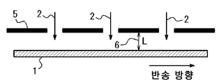
6. 상기 패터닝의 노광은, 상기 강판과 이간하여 설치한 마스크의 개구부를 통과한 빛을, 상기 강판에 조사함으로써 행하고, 또한, 상기 마스크와 상기 강판의 거리가 50㎛ 이상 5000㎛ 이하인 것을 특징으로 하는, 상기 1∼4 중 어느 한 항에 기재된 방향성 전자 강판의 제조 방법. 6. The exposure of the patterning is performed by irradiating the steel plate with light passing through an opening of a mask provided so as to be spaced apart from the steel plate, and the distance between the mask and the steel plate is not less than 50 μm and not more than 5000 μm Wherein the directional electromagnetic steel sheet is produced by the method according to any one of the first to fourth aspects.
7. 상기 패터닝의 노광은, 렌즈 및/또는 미러를 통하여, 상기 강판과 이간하여 설치한 마스크의 개구부를 통과한 빛을, 상기 강판에 조사함으로써 행하는 것을 특징으로 하는, 상기 1∼4 중 어느 한 항에 기재된 방향성 전자 강판의 제조 방법. 7. The patterning exposure method according to any one of 1 to 4 above, wherein the exposure of the patterning is performed by irradiating the steel plate with light passing through an opening of a mask provided apart from the steel plate through a lens and / Wherein said method comprises the steps of:
본 발명에 의하면, 변형 제거 어닐링을 실시해도 자구 세분화의 효과가 소실되지 않고, 양호한 철손을 유지할 수 있는 방향성 전자 강판을 높은 생산성으로 제조할 수 있다. According to the present invention, even if the deformation-removing annealing is performed, the effect of segmentation of the magnetic domain is not lost, and the grain-oriented electrical steel sheet capable of maintaining a good iron loss can be produced with high productivity.
도 1은 직접 묘화형(direct imaging)에 의한 노광 장치의 일 예를 나타내는 도면이다.
도 2는 본 발명에 있어서의 광 조사시의, 마스크 부재의 사용의 일 예(마스크가 강판과 수평 방향으로 설치됨)를 설명하는 도면이다.
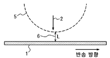
도 3은 본 발명에 있어서의 광 조사시의, 마스크 부재의 사용의 다른 예(마스크가 만곡하여 설치됨)를 설명하는 도면이다.
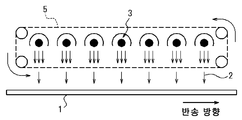
도 4는 본 발명에 있어서의 광 조사시의, 마스크 부재의 사용의 다른 예(마스크를 강판과 수평으로 설치하고, 강판의 이동에 따라서 마스크의 개구부를 이동시킴)를 설명하는 도면이다.
도 5는 투영형(projection)에 의한 노광 장치의 일 예를 나타내는 도면이다. 1 is a view showing an example of an exposure apparatus by direct imaging.
2 is a view for explaining an example of use of a mask member (mask is installed in a horizontal direction with a steel sheet) at the time of light irradiation in the present invention.
3 is a view for explaining another example of use of the mask member (mask is provided curved) at the time of light irradiation in the present invention.
4 is a view for explaining another example of the use of the mask member (the mask being provided horizontally with the steel sheet and moving the opening of the mask in accordance with the movement of the steel sheet) during light irradiation in the present invention.
5 is a diagram showing an example of an exposure apparatus by projection.
(발명을 실시하기 위한 형태)(Mode for carrying out the invention)
이하, 본 발명을 구체적으로 설명한다. Hereinafter, the present invention will be described in detail.
우선, 발명자들이 본 발명을 착상하기에 이른 실험으로서, 레지스트 피막의 도포 방법에 대해서 검토를 행한 실험의 설명을 행한다. First, as an experiment to which the present inventors have conceived the present invention, an experiment in which a coating method of a resist film is examined will be described.
실험에 사용한 방향성 전자 강판은, 방향성 전자강용 슬래브(slab)를 열간 압연하고, 그 후 필요에 따라서 열연판 어닐링을 행한 후, 1회 또는 중간 어닐링을 사이에 두는 2회의 냉간 압연에 의해 최종 제품 판두께로 하고, 그 후, 탈탄 어닐링, 이어서 최종 마무리 어닐링을 실시하고, 그 후, 덧칠 코팅을 실시하여 제조했다. The directional electromagnetic steel sheet used in the experiment was obtained by subjecting a slab of a directional electromagnetic steel to hot rolling and then performing hot-rolled sheet annealing if necessary, followed by cold rolling two times with intermediate or intermediate annealing, And then decarburization annealing and subsequent final annealing were carried out, and thereafter, overcoating was performed.
상기의 제조 공정 중, 0.23㎜의 최종 제품 판두께로 한 최종 냉연판의 편면에, 지철 노출부가 약 100㎛의 폭으로 압연 방향과 직각 방향으로 선 형상으로 연장되고, 그 압연 방향에서의 간격이 5㎜가 되는 패턴을 가진 레지스트 피막의 패터닝을, 상이한 방법으로 행했다. In the above manufacturing process, the base steel exposed portion extends linearly in a direction perpendicular to the rolling direction at a width of about 100 mu m on one surface of a final cold-rolled sheet having a final product sheet thickness of 0.23 mm, The patterning of the resist film having a pattern of 5 mm was performed by a different method.
여기에서, 패터닝의 방법 중 하나는, 에폭시계 수지를 주성분으로 하는 레지스트를 그라비아 오프셋 인쇄에 의해 인쇄하여 건조하는 것으로 했다. 또한, 다른 하나의 방법은, 고무계 수지에 감광재로서 비스아지드(bisazide) 화합물을 포함하는 레지스트 피막을 강판 표면에 균일하게 도포하고, 홈부만이 차폐된 마스크를 강판면의 100㎛ 위에 고정하여, 마스크를 통하여 자외선을 조사한 후, 알칼리 현상액에 침지함으로써, 홈부의 피막만 제거하는 것으로 했다. Here, one of the patterning methods is to print a resist containing an epoxy resin as a main component by gravure offset printing and dry it. In another method, a resist coating film containing a bisazide compound as a photosensitive material is uniformly applied to a rubber-based resin on the surface of a steel sheet, and a mask shielding only the groove portion is fixed on the surface of the steel sheet to 100 m , And then irradiated with ultraviolet rays through a mask, and then immersed in an alkali developing solution to remove only the coating of the groove portion.
후자의 방법으로 이용한 레지스트 피막은, 일반적으로, 반도체 제조에서 채용되고 있는 포토리소그래피 기술에 이용되는 네거티브형 레지스트이고, 노광부가 경화하여 현상시에 불용성(insoluble) 물질이 된다. The resist film used in the latter method is generally a negative type resist used in a photolithography technique employed in semiconductor manufacturing, and the exposed portion is cured to become an insoluble material at the time of development.
또한, 양자의 방법에서는, 함께, 레지스트 피막의 막두께를 2㎛로 했다. 패터닝 공정의 후, 레지스트 피막을 도포한 강판을 NaCl 수용액 중에 침지하여, 지철 노출부에 대한 전류 밀도 ρ를 바꾸어, 전하량이 일정해지는 조건으로 전해 에칭을 실시했다. In both methods, the film thickness of the resist film was set to 2 mu m. After the patterning step, the steel sheet coated with the resist coating was immersed in an NaCl aqueous solution to change the current density rho to the base metal exposed portion, and the electrolytic etching was carried out under the condition that the amount of charge became constant.
또한, 본 발명에 있어서의 지철 노출부에 대한 전류 밀도 ρ는, 전해 에칭에 이용하는 전극의 침지 부분과 동등의 면적(본 발명에서는, 간단히, 전극의 면적이라고도 함)을 강판 표면에서 선택한 경우의 지철 노출부의 면적을 S[㎠], 투입 전류를 I[A]로 했을 때, ρ=I/S[A/㎠]로 정의된다. 즉, 전극의 전해 용액에 침지하고 있는 부분의 면적을 R[㎠]로 한 경우, 전해되는 강판의 임의의 위치의 면적 R[㎠]의 부분을 선택하면, 그 부분의 지철 노출부의 면적이 S[㎠]가 된다는 것이다. The current density? Of the steel-base exposed portion in the present invention is a value obtained by subtracting the area (equivalent to the electrode area in the present invention, simply referred to as the area of the electrode) equivalent to the electrode- Is defined as p = I / S [A / cm 2], where S [cm 2] is the area of the exposed portion and I [A] is the applied current. That is, when the area R [cm 2] of an arbitrary position of the steel sheet to be electrolyzed is selected when the area of the portion of the electrode immersed in the electrolytic solution is R [cm 2], the area of the steel- [Cm < 2 >].
이어서, 전해 에칭 후에 잔류하고 있는 레지스트 피막을 유기 용제에 녹여 박리한 후, 접촉식의 표면 조도계를 이용하여 홈 폭과 홈 깊이를 조사했다. 또한, 홈 폭과 홈 깊이는, 아래로 볼록하게 되어 있는 영역의 가장 깊은 부분의 깊이를 홈 깊이, 홈 깊이에 대하여 절반분의 깊이에 있는 위치에서의 홈의 양단이 되는 2점의 거리를 홈 폭으로 하고, 샘플의 상이한 5개의 홈에 대해서, 각각 4개소씩 측정을 행하여, 합계 20점의 평균으로 산출했다. Subsequently, the resist film remaining after the electrolytic etching was dissolved in an organic solvent and peeled off, and then the groove width and groove depth were examined using a contact type surface roughness meter. The groove width and the groove depth are set such that the depth of the deepest portion of the downwardly convex region is the groove depth and the distance of two points which are both ends of the groove at the position which is half the depth of the groove depth, Width, and the measurement was performed for each of the four different grooves in the five different grooves of the sample, and the average was calculated by a total of 20 points.
또한, 상기 샘플의 탈탄 어닐링을 행하고, 최종 마무리 어닐링을 행한 후, 덧칠 코팅을 실시하여 제품으로 했다. Further, the sample was subjected to decarburization annealing, final annealing was performed, and then a coating was applied to obtain a product.
이렇게 하여 얻어진 제품판으로부터 시험편을 잘라내어, 변형 제거 어닐링을 실시한 후, JIS C2550에 기재된 방법으로 철손 W17 /50을 측정했다. In this way a test piece cut out from the obtained steel sheet product, and then subjected to stress-relief annealing were measured for core loss W 17/50 by the method described in JIS C2550.
그 결과를 표 1에 나타낸다. 또한, 기본 전류 밀도는, 투입 전류 I를 전극의 면적 R로 나눈 I/R[A/㎠]로 정의되는 전류 밀도이다. The results are shown in Table 1. The basic current density is a current density defined by I / R [A / cm < 2 >] of the applied current I divided by the area R of the electrode.

표 1로부터 분명한 바와 같이, 그라비아 오프셋 인쇄에 의해 레지스트 피막을 도포한 방법에서는, 전류 밀도 ρ가 7.5A/㎠를 초과하면 홈 폭이 넓어져 홈 깊이가 얕아지고, 철손이 열화해가는 데에 대하여, 네거티브형 레지스트를 도포하여 노광·현상을 행한 방법에서는, 전류 밀도가 커져도 홈 폭 및 홈 깊이는 크게 변화하지 않고, 그라비아 오프셋 인쇄에 의한 방법보다도 철손이 양호했다. As is apparent from Table 1, in the method in which the resist coating is applied by gravure offset printing, when the current density p exceeds 7.5 A /
이와 같이, 감광성 레지스트를 강판 표면에 도포하고, 노광, 현상에 의해 소망하는 패턴을 갖는 지철 노출부를 강판 표면에 형성시킨 후, 높은 전류 밀도의 전해 에칭에 의해 지철 노출부를 에칭함으로써, 본 발명은, 고생산성과 저철손을 양립할 수 있는 내열형 자구 세분화 기술이 되는 것을 알 수 있었다. Thus, by applying a photosensitive resist to the surface of a steel sheet, forming a steel-iron exposed portion having a desired pattern on the steel sheet surface by exposure and development, and etching the steel-steel exposed portion by electrolytic etching with a high current density, It is found that the heat-resistant magnetic domain refining technology capable of achieving high productivity and low iron loss can be achieved.
이하, 본 발명을 더욱 상세하게 설명한다. Hereinafter, the present invention will be described in more detail.
본 발명에 이용하는 방향성 전자 강판용 소재는, 주조에 의해 슬래브로서 공급한다. 주조의 방법은 특별히 한정하지 않는다. 소재가 되는 슬래브의 조성은, 방향성 전자 강판용으로서 일반적으로 이용되는 것이면 특별히 한정하지 않지만, 예를 들면, Si: 2∼5mass%, C: 0.002∼0.10mass%, Mn: 0.01∼0.80mass%, Al: 0.002∼0.05mass%, N: 0.003∼0.02mass%를 함유하고, 잔부 Fe 및 불가피적 불순물로 할 수 있다. The material for a grain-oriented electrical steel sheet used in the present invention is supplied as a slab by casting. The casting method is not particularly limited. The composition of the slab to be the material is not particularly limited as long as it is generally used for the grain-oriented electrical steel sheet. For example, the composition of Si: 2 to 5 mass%, C: 0.002 to 0.10 mass%, Mn: 0.01 to 0.80 mass% : 0.002 to 0.05 mass%, and N: 0.003 to 0.02 mass%, and the balance Fe and inevitable impurities.
이어서, 필요에 따라서 슬래브를 가열하여, 열간 압연하여 열연 강판(열연판)으로 한 후, 필요에 따라서 열연판 어닐링을 실시한다. 열연판 어닐링의 온도는 특별히 한정하지 않지만, 예를 들면 800∼1200℃의 범위로 하는 것이 자기 특성(magnetic properties) 향상의 관점에서 바람직하다. Subsequently, the slab is heated and hot-rolled as required to form a hot-rolled steel sheet (hot-rolled steel sheet), and then hot-rolled sheet annealing is carried out if necessary. The temperature of the hot-rolled sheet annealing is not particularly limited, but is preferably in the range of, for example, 800 to 1200 占 폚 in view of improvement of magnetic properties.
또한, 1회 또는 중간 어닐링을 포함하는 2회 이상의 냉간 압연을 실시하여, 냉연 강판(이하, 간단히 강판이라고도 함)으로 한다. 이들 방법은 공지의 방법으로 행하면 좋다. Further, cold rolling is carried out twice or more including one time or intermediate annealing to obtain a cold-rolled steel sheet (hereinafter, simply referred to as a steel sheet). These methods may be carried out by a known method.
이후의 공정에서 냉연 강판에의 레지스트의 밀착성을 높이는 것을 목적으로 하여, 레지스트 도포의 직전에 수산화 나트륨 용액 등의 알칼리 용액으로 강판 표면의 탈지·건조를 하는 것이 바람직하다. It is preferable to degrease and dry the surface of the steel sheet with an alkali solution such as sodium hydroxide solution immediately before the application of the resist in order to improve the adhesion of the resist to the cold-rolled steel sheet in subsequent steps.
이와 같이 하여 얻어진 냉연 강판의 편면 또는 양면에 감광성 수지를 포함하는 레지스트 피막을 도포한다. A resist film containing a photosensitive resin is applied to one side or both sides of the thus obtained cold rolled steel sheet.
레지스트의 도포 방법은 특별히 한정하지 않지만, 띠 형상의 강판(강대라고도 함)에 균일하게 도포하는 관점에서, 롤 코터(roll coater)나 커튼 코터(curtain coater), 바 코터(bar coater) 등의 방법을 이용할 수 있다. 또한, 레지스트의 도포 후에, 레지스트를 고체화시켜 밀착성을 높이는 것을 목적으로 하여, 50∼300℃에서 1∼300초의 범위의 열처리를 가하는 것이 바람직하다. The method of applying the resist is not particularly limited, but a method such as a roll coater, a curtain coater, a bar coater, or the like may be used from the viewpoint of uniformly applying the resist to a strip-shaped steel sheet (also referred to as a steel strip) Can be used. In addition, after application of the resist, it is preferable to apply a heat treatment in the range of 50 to 300 占 폚 for 1 to 300 seconds for the purpose of solidifying the resist to improve the adhesion.
본 발명에 이용하는 레지스트에는, 노광 부분이 현상액에 대하여 용해성이 증가하는 포지티브형 레지스트가 적합하다. 포지티브형 레지스트에서는 노광 부분이 현상에 의해 제거되기 때문에, 노광 부분을 소면적으로 할 수 있기 때문이다. 즉, 소망하는 홈 폭으로 줄인 빛을, 직접, 강판 상에서 주사하여, 홈 위치에 상당하는 노광 부분의 레지스트를 변성시키면 좋다. 이와 같이 포지티브형 레지스트는, 마스크와 같은 복잡한 기구를 통하지 않고 임의의 패터닝을 행할 수 있기 때문에, 방향성 전자 강판의 내열형 자구 세분화에 적절한 레지스트 재료이다. The resist used in the present invention is preferably a positive type resist in which the exposed portion is increased in solubility in a developing solution. This is because, in the positive type resist, the exposed portion is removed by development, the exposed portion can be made small in area. That is, light reduced to a desired groove width may be directly scanned on a steel plate to denature the resist of the exposed portion corresponding to the groove position. As described above, since the positive type resist can be subjected to arbitrary patterning without passing through a complicated mechanism such as a mask, it is a resist material suitable for refining the heat resistant type magnetic domain of the grain-oriented electrical steel sheet.
여기에서, 포지티브형 레지스트는 알칼리 가용성 수지 및 빛에 의해 산을 발생하는 화합물을 주성분으로 한다. 본 발명에 있어서, 포지티브형 레지스트의 성분은 특별히 한정되는 것은 아니지만, 예를 들면, 알칼리 가용성 수지로서, 노볼락 수지, 폴리아미드계 수지, 아크릴 수지, 환상 올레핀 수지 등을 이용할 수 있다. 빛에 의해 산을 발생하는 화합물은 퀴논디아지드 화합물이나 오늄염 등을 이용할 수 있다. Here, the positive-type resist mainly contains an alkali-soluble resin and a compound which generates an acid by light. In the present invention, the components of the positive-type resist are not particularly limited. For example, novolak resins, polyamide resins, acrylic resins, cyclic olefin resins and the like can be used as the alkali-soluble resins. As the compound which generates an acid by light, a quinone diazide compound or an onium salt can be used.
본 발명에 이용하는 레지스트에는, 노광 부분이 현상액에 대하여 난용해성(low solubility)이 되는 네거티브형 레지스트를 이용하는 것도 바람직하다. 네거티브형 레지스트에서는 노광 부분이 현상시에 잔존하기 때문에, 전해 에칭시에 지철을 노출시키고 싶은 부분만을 남긴 마스크를 사용하여, 마스크를 통하여 빛을 조사함으로써, 빛을 주사 하는 일 없이 패터닝을 행할 수 있기 때문이다. In the resist used in the present invention, it is also preferable to use a negative type resist in which the exposed portion has poor solubility with respect to the developer. In the negative-type resist, since the exposed portion remains at the time of development, patterning can be performed without irradiating light by irradiating light through the mask using a mask that leaves only the portion of the substrate to be exposed during electrolytic etching Because.
또한, 네거티브형 레지스트는, 강판에의 밀착성이 우수하기 때문에, 강판을 반송 중에 진동 등으로 레지스트가 박리하는 것을 억제할 수 있다. 네거티브형 레지스트의 성분으로서는, 환화 고무(cyclized rubber)와 감광제로서 비스아지드 화합물을 함유하는 것이 잘 알려져 있다. 이들 성분을 포함하는 레지스트는, 현상에 유기 용매를 필요로 한다. 현상에 알칼리 용액을 사용 가능한 레지스트로서는, 폴리실록산이나 아크릴 수지 등의 알칼리 가용 수지와, 다관능 아크릴 모노머 및 α-아미노알킬페논 화합물이나 옥심에스테르 화합물 등의 광 라디칼 중합 개시재를 함유하는 것이 알려져 있다. Further, since the negative type resist has excellent adhesion to the steel sheet, it is possible to suppress the resist from peeling off due to vibration or the like during transportation of the steel sheet. As a component of the negative type resist, it is well known that a cyclized rubber and a bisazide compound as a photosensitizer are contained. Resists containing these components require an organic solvent for development. As resists which can use an alkali solution for the development, it is known that an alkali-soluble resin such as polysiloxane or acrylic resin and a photo-radical polymerization initiator such as a polyfunctional acrylic monomer and an? -Aminoalkylphenone compound or an oxime ester compound are contained.
본 발명에 이용하는 레지스트에는, 그 사용이 용이한 점에서 우수한 화학 증폭형의 레지스트가 바람직하다. 화학 증폭형 레지스트란, 광(光) 산(酸) 발생제를 함유하고, 노광에 의해 광 산 발생제로부터 발생한 산을 촉매로 하는 반응을 이용하는 레지스트이다. The resist used in the present invention is preferably a chemically amplified resist excellent in ease of use. A chemically amplified resist is a resist which contains a photoacid generator and uses a reaction with an acid generated from the photo acid generator as a catalyst by exposure.
화학 증폭형 레지스트는 포지티브형과 네거티브형의 2종류가 있다. 화학 증폭 포지티브형 레지스트는, 광 산 발생제로부터 발생한 산이 알칼리 가용성 수지의 알칼리 가용기를 보호하는 보호기의 탈보호 반응을 일으킴으로써, 광 조사부가 알칼리 가용성이 된다. 한편, 화학 증폭 네거티브형 레지스트는, 광 산 발생제로부터 발생한 산이 알칼리 가용기와 가교제의 가교 반응을 일으켜, 알칼리 불용(alkali-insolubility)이 된다. 화학 증폭형 레지스트는 상기한 바와 같이 산을 촉매로 한 반응을 이용하고 있기 때문에, 노광에 대하여 고감도이고, 노광 시간의 단축을 실현할 수 있어, 생산성을 보다 높이는 것이 가능해진다. There are two types of chemically amplified resists, positive type and negative type. In the chemically amplified positive type resist, the acid generated from the photo acid generator causes a deprotection reaction of a protecting group for protecting the alkali-soluble group of the alkali-soluble resin, so that the irradiated portion becomes alkali-soluble. On the other hand, in a chemically amplified negative type resist, an acid generated from a photo acid generator causes a cross-linking reaction of an alkali-soluble group and a cross-linking agent to become alkali-insolubility. Since the chemically amplified resist uses the acid-catalyzed reaction as described above, it is possible to realize a high sensitivity to exposure, shorten the exposure time, and improve the productivity.
본 발명에 있어서, 화학 증폭형 레지스트의 구체적인 성분은, 특별히 한정하는 것은 아니지만, 예를 들면, 화학 증폭형의 포지티브형 레지스트에서는, 폴리비닐페놀 등 페놀성 수산기나 카복실기를 갖는 알칼리 가용 수지에 ter-부톡시카보닐 등을 결합하여 알칼리 불용화한 수지가 이용된다. 화학 증폭형의 네거티브형 레지스트는, 알칼리 가용 수지에 가교제로서 테트라메톡시글리코유릴 등을 함유하고 있다. 또한, 광 산 발생제로서는, 오늄염, 니트로벤질에스테르, 디아조메탄 등이 알려져 있다. In the present invention, a specific component of the chemically amplified resist is not particularly limited. For example, in a chemically amplified positive resist, a phenolic hydroxyl group such as polyvinylphenol or an alkali- Butoxycarbonyl or the like is bonded thereto to make the resin insoluble in alkali. The chemically amplified negative resist contains tetramethoxyglycoluril and the like as a crosslinking agent in an alkali-soluble resin. As the photoacid generator, onium salts, nitrobenzyl esters, diazomethane and the like are known.
이들 레지스트는, 적당한 용제에 용해하고, 적절한 점도로 조절하여 이용한다. 용제는 수지와 감광제에 대하여 불활성이면 특별히 제한은 없고, 예를 들면, 알칼리 용해 수지에 대해서는 프로필렌글리콜모노메틸에테르아세테이트, 아세트산 이소프로필, 디메틸술폭사이드 등을 이용할 수 있다. 한편, 환화 고무를 베이스로서 이용하는 경우는 유기 용제를 이용한다. These resists are dissolved in a suitable solvent and adjusted to an appropriate viscosity. The solvent is not particularly limited as long as it is inert with respect to the resin and the photosensitizer. For example, propylene glycol monomethyl ether acetate, isopropyl acetate, dimethylsulfoxide and the like can be used for the alkali dissolving resin. On the other hand, when a cyclic rubber is used as a base, an organic solvent is used.
상기와 같이 하여 레지스트가 도포된 강판은, 레지스트 중의 용매를 증발시시키고, 강판에 밀착시키는 것을 목적으로 하여 가열 처리를 실시한다. 가열 처리의 온도·시간은 사용하는 레지스트에 맞추어 조정하지만, 대체로 50∼150℃에서 1∼500초 정도로 하는 것이 바람직하다. The steel sheet coated with the resist as described above is subjected to heat treatment for evaporating the solvent in the resist and bringing it into close contact with the steel sheet. The temperature and time of the heat treatment may be adjusted in accordance with the resist used, but it is preferable that the temperature and time are generally set at about 50 to 150 DEG C for about 1 to 500 seconds.
이어서, 레지스트를 도포한 면에 빛을 조사하여 노광한다. 이용하는 광원은 사용하는 레지스트의 감광제에 따라서 변경한다. 예로서, 포지티브형 레지스트나 네거티브형 레지스트의 주된 감광대인 g선(436㎚)이나 i선(405㎚) 부근의 광원으로서 고압 수은등이나 레이저 다이오드를 이용할 수 있다. 화학 증폭형 레지스트에는 KrF 엑시머 레이저(248㎚)나 ArF 엑시머 레이저(193㎚) 등을 이용할 수 있다. 또한, 필요에 따라서 X선이나 전자빔을 이용할 수도 있다. Then, the surface coated with the resist is exposed to light. The light source used is changed according to the photosensitizer of the resist to be used. For example, a high-pressure mercury lamp or a laser diode can be used as a light source in the vicinity of the g-line (436 nm) or the i-line (405 nm), which is the main photosensitive region of the positive type resist or the negative type resist. As the chemically amplified resist, a KrF excimer laser (248 nm) or an ArF excimer laser (193 nm) can be used. In addition, X-rays or electron beams may be used as needed.
내열형 자구 세분화를 목적으로 하는 본 발명에 있어서, 노광을 행하는 방법으로서는, 빛을 강판 상에서 주사하여 노광을 행하는 직접 묘화형이 적합하다. 이 방법에서는, 빛의 조사 방향과 강판의 이동 방향을 동기시키는 것만으로 좋고, 마스크와 조합한 고가의 노광 장치를 이용하는 일 없이 노광을 행할 수 있다. 상기의 노광 방식에 이용하는 레지스트는 특별히 지정되는 것은 아니지만, 포지티브형 또는 화학 증폭 포지티브형 레지스트와 조합하여 이용하는 것이 바람직하다. 왜냐하면, 강판의 표면적에 비하여 면적이 작은 홈 형성 부분만을 적절한 스팟계(spot-type)의 빛으로 주사하면 좋기 때문에, 광학계의 주사 부하를 저감하여, 단시간에 노광을 행할 수 있기 때문이다. 네거티브형 레지스트를 이용하는 경우는, 홈 형성부 이외의 영역 상을 빛으로 주사하면 좋다. 직접 묘화형에 의한 노광 장치의 일 예를 도 1에 나타낸다. 또한, 도면 중, 1은 강판, 2는 빛, 3은 광 조사 장치(광원), 4는 미러(mirror)이다. As a method of performing exposure in the present invention aiming at refining the heat resistant type magnetic domain, a direct imaging type in which light is scanned on a steel plate and exposure is performed is suitable. In this method, it is only necessary to synchronize the irradiation direction of light with the moving direction of the steel sheet, and exposure can be performed without using an expensive exposing apparatus combined with a mask. The resist used in the above exposure method is not particularly specified, but it is preferably used in combination with a positive type or chemically amplified positive type resist. This is because only the groove forming portion having a smaller area than the surface area of the steel sheet can be scanned with a suitable spot-type light, so that the scanning load of the optical system can be reduced and the exposure can be performed in a short time. When a negative type resist is used, an area other than the groove forming part may be scanned with light. FIG. 1 shows an example of an exposure apparatus using a direct imaging type. In the drawings,
또한, 강판 상을 주사하는 빛의 광원으로서는, 지향성이 높고, 주사의 제어가 용이한 레이저를 이용하는 것이 바람직하다. 레이저 광원으로서는, 고출력이 얻어지는 개체 UV 레이저나 Ar+ 레이저 등을 사용하는 것이 바람직하다. 또한, 생산성의 관점에서, 레지스트의 노광량은 지나치게 높지 않은 것이 바람직하고, 500㎽/㎠ 이하로 하는 것이 바람직하다. 보다 바람직하게는 200㎽/㎠ 이하이다. 레이저의 스팟 지름은 소망하는 홈 폭과 동등하면 좋고, 10∼250㎛의 범위로 하는 것이 바람직하다. As the light source for scanning the steel sheet, it is preferable to use a laser having high directivity and easy control of scanning. As the laser light source, it is preferable to use an individual UV laser or an Ar + laser which can obtain high output. From the viewpoint of productivity, the exposure amount of the resist is preferably not excessively high, and is preferably 500 mW /
또한, 본 발명에 이용하는 노광 방법으로서는, 마스크를 강판 표면 부근에 설치하는 근접 마스크형이 적합하다. 포지티브형 또는 화학 증폭 포지티브형 레지스트를 이용하는 경우는, 홈 부분이 개구된 마스크를 이용한다. 네거티브형 또는 화학 증폭 네거티브형 레지스트를 이용하는 경우는, 홈 부분이 차폐되고, 비(非)홈 형성 영역이 개구된 마스크를 이용한다. 노광은 광원과 강판의 사이에 마스크를 설치하여, 마스크의 개구부로부터 강판 상에 빛이 도달함으로써 행해진다. As the exposure method used in the present invention, a proximity mask type in which a mask is provided near the surface of a steel sheet is suitable. When a positive type or chemically amplified positive type resist is used, a mask having a groove portion opened is used. When a negative type or chemically amplified negative type resist is used, a mask in which the groove portion is shielded and the non-groove forming region is opened is used. The exposure is carried out by providing a mask between the light source and the steel sheet and reaching the light from the opening of the mask onto the steel sheet.
이러한 차광 방법을 이용함으로써, 레이저와 같이 지향성이 높고, 미세한 스팟 지름의 빛을 얻는 것이 곤란한 염가의 광원을 이용하여 노광을 실시하는 것이 가능해진다. By using such a light shielding method, it is possible to perform exposure using an inexpensive light source, such as a laser, which has high directivity and is difficult to obtain light with a small spot diameter.
상기 노광시에, 마스크를 강판과 접촉시키면, 레지스트에 흠집이나 박리가 생겨, 전해 에칭시에 의도하지 않는 영역이 에칭됨으로써 철손의 열화를 초래한다. 그래서, 본 발명에 있어서는, 마스크와 강판은 접촉시키지 않고 노광을 행한다. When the mask is brought into contact with the steel sheet during the exposure, scratches or peeling occur in the resist, and unintentional areas are etched at the time of electrolytic etching, resulting in deterioration of iron loss. Thus, in the present invention, exposure is performed without bringing the mask and the steel sheet into contact with each other.
이때, 마스크와 강판의 거리는 50㎛ 이상 5000㎛ 이하로 하는 것이 바람직하다. 여기에서, 마스크와 강판의 거리란, 도 2에 나타내는 바와 같이 마스크가 강판과 수평 방향으로 설치되는 경우는, 마스크와 강판의 연직 방향의 거리(L)로 한다. 또한, 도 3에 나타내는 바와 같이 마스크가 만곡하여 설치되는 경우는, 마스크와 강판의 최근접 거리(L)로 한다. 또한, 도 2, 3 중, 5는 마스크 부재, 6은 마스크와 강판의 거리: L이다. At this time, the distance between the mask and the steel sheet is preferably 50 占 퐉 or more and 5000 占 퐉 or less. Here, the distance between the mask and the steel sheet means the distance L between the mask and the steel sheet in the vertical direction when the mask is provided in the horizontal direction with respect to the steel sheet as shown in Fig. When the mask is curved as shown in Fig. 3, the closest distance L between the mask and the steel plate is set. 2 and 3,
여기에서, 마스크의 강판과의 거리가 지나치게 크면 빛의 회절에 의해 조사 영역 이외에도 빛이 도달하게 되어, 적절한 폭의 홈을 형성할 수 없게 된다. 그 때문에, 마스크와 강판의 거리는 5000㎛ 이하로 하는 것이 바람직하다. 한편, 마스크와 강판의 거리가 지나치게 작으면 강판의 진동에 의해, 강판과 마스크가 접촉하는 경우가 있기 때문에, 50㎛ 이상으로 하는 것이 바람직하다. 마스크의 노광부는 강판과 수평으로 설치하여, 강판의 이동에 따라서 마스크와 광원을 이동시키는 타입이라도 좋고, 화학 증폭형 레지스트 등으로 충분히 단시간에 노광이 완료되는 경우는, 도 4의 노광 장치와 같이 마스크의 개구부만을 이동시켜, 위치를 고정한 광원으로부터 주기적으로 빛을 조사하는 방법이라도 좋다. 마스크의 홈 형성 영역의 폭은 강판 상에 형성하는 지철 노출부의 폭과 거의 등배로 하는 것이 좋지만, 마스크와 강판의 거리에 따라서 축척을 변경해도 좋다. Here, if the distance between the mask and the steel plate is excessively large, light may reach other than the irradiation region due to diffraction of light, so that grooves of appropriate width can not be formed. Therefore, it is preferable that the distance between the mask and the steel sheet is 5000 mu m or less. On the other hand, if the distance between the mask and the steel plate is excessively small, the steel plate and the mask may come into contact with each other due to the vibration of the steel plate. The exposure unit of the mask may be of a type that is horizontally provided with the steel plate and moves the mask and the light source in accordance with the movement of the steel plate. When the exposure is completed sufficiently in a short time using a chemically amplified resist or the like, It is also possible to radiate light periodically from a light source in which the position is fixed. The width of the groove forming region of the mask is preferably approximately equal to the width of the base metal exposed portion formed on the steel plate, but the scale may be changed in accordance with the distance between the mask and the steel plate.
또한, 본 발명에 이용하는 노광 방법으로서, 마스크를 통과하여 얻어진 상(image)이 렌즈 및/또는 미러에 의한 광학계에 의해 레지스트 상에 투영하는 투영형이 적합하다. 이 방법에 의하면, 마스크를 강판에 접근시킬 필요가 없고, 강판의 반송에 수반하는 진동 등으로 마스크와 강판이 접촉하는 일이 없기 때문에, 마스크의 결손을 막아, 안정적으로 노광을 유지할 수 있다. 강판 상에 투영되는 상은 마스크와 등배라도 좋고, 강판 상에서 상이 소망하는 스케일이 되도록 축소·확대하여 투영해도 좋다. 상을 축소하는 경우는 고(高)정밀도의 노광이 가능해져, 안정적으로 노광을 유지할 수 있다. 한편, 확대 투영한 경우는, 노광의 정밀도는 축소의 경우에 비해 뒤떨어지기는 하지만, 마스크의 사이즈를 작게 할 수 있어, 비용면에서 우수하다. 투영형에 의한 노광 장치의 일 예를 도 5에 나타낸다. 또한, 도면 중, 7은 렌즈이다. Further, as the exposure method used in the present invention, a projection type in which an image obtained through a mask is projected onto a resist by an optical system of a lens and / or a mirror is suitable. According to this method, since the mask does not need to approach the steel plate and the mask and the steel plate do not come into contact with each other due to the vibration accompanying the conveyance of the steel plate, the mask can be prevented from being defected and the exposure can be stably maintained. The image to be projected on the steel plate may be an image of a mask or the like, and the image may be projected on the steel plate so that the image is scaled to a desired scale. When the image is reduced, high-precision exposure is possible, and exposure can be stably maintained. On the other hand, in the case of enlarged projection, the accuracy of exposure is inferior to that in the case of reduction, but the size of the mask can be reduced, which is excellent in cost. An example of an exposure apparatus based on a projection type is shown in Fig. In the figure, reference numeral 7 denotes a lens.
도 4 및 5에서는, 노광 방법에 따른 노광 장치의 일 예를 나타냈지만, 이들은 어디까지나 일 예이고, 다른 장치에 의한 노광 방법의 실시를 전혀 배제하는 것은 아니다. Although Figs. 4 and 5 show an example of the exposure apparatus according to the exposure method, these are merely examples, and the practice of the exposure method by other apparatus is not excluded at all.
여기에서, 화학 증폭형 레지스트를 이용하는 경우는, 노광 후에 적절한 온도와 시간으로 열 처리를 행한다. 이에 따라, 화학 증폭 포지티브형 레지스트에서는, 노광에 의해 광 산 발생제로부터 발생한 산이 촉매가 되어 알칼리 가용성 수지의 알칼리 가용기의 보호기의 탈보호 반응을 촉진하여, 노광부가 알칼리 가용으로 변화한다. 네거티브형에 있어서는 알칼리 가용 수지와 가교제가 산을 촉매로 하여 가교 반응을 일으켜, 노광부가 알칼리 비가용화한다. 처리 온도 및 시간은 이용하는 레지스트에 따라 상이하지만, 50∼200℃의 온도에서 1∼300초 정도의 시간으로 하는 것이 좋다. Here, when a chemically amplified resist is used, heat treatment is performed at an appropriate temperature and time after exposure. Thus, in the chemically amplified positive type resist, an acid generated from the photo acid generator by exposure becomes a catalyst, thereby promoting the deprotection reaction of the protecting group of the alkali-soluble group of the alkali-soluble resin, and the exposed portion is changed to alkali-soluble. In the negative type, an alkali-soluble resin and a cross-linking agent cause a cross-linking reaction with an acid as a catalyst, so that the alkali-solubility of the exposed portion is increased. Although the treatment temperature and time vary depending on the resist used, it is preferable that the treatment time is from 1 to 300 seconds at a temperature of 50 to 200 캜.
이어서, 현상에 의해 홈 형성 부분의 레지스트를 제거하고, 지철을 노출시킴으로써 패터닝을 완료한다. 현상액은 레지스트에 맞춘 것을 사용한다. 알칼리 가용 수지를 베이스로 하는 레지스트에 있어서는, 수산화 칼륨 수용액 등의 무기 알칼리나, 수산화 테트라메틸암모늄 수용액 등의 유기 알칼리를 이용할 수 있다. 환화 고무를 베이스로 하는 네거티브형 레지스트를 이용하는 경우는, 케톤계 용제, 에스테르계 용제, 알코올계 용제 등의 유기 용제를 이용한다. 현상의 공정은 특별히 지정하는 것은 아니지만, 강판을 현상액으로 채운 조(tank)에 침지하는 방법이나, 현상액을 스프레이로 분사하는 방법 등이 생산 효율의 관점에서 바람직하다. 현상의 후, 필요에 따라서 린스제나 순수로 세정하는 공정을 행하는 것이 바람직하다. Subsequently, the resist in the groove forming portion is removed by development, and the patterning is completed by exposing the base metal. Use a developer that matches the resist. In a resist based on an alkali-soluble resin, an inorganic alkali such as an aqueous solution of potassium hydroxide or an organic alkali such as an aqueous solution of tetramethylammonium hydroxide can be used. In the case of using a negative resist based on a cyclic rubber, an organic solvent such as a ketone solvent, an ester solvent, or an alcohol solvent is used. Although the development process is not particularly specified, a method of immersing a steel sheet in a tank filled with a developer, a method of spraying the developer with a spray, and the like are preferable from the viewpoint of production efficiency. After the development, it is preferable to carry out a step of washing with rinsing agent or pure water as necessary.
이 후, 필요에 따라서 건조 처리를 행함으로써, 용제를 증발시키는 레지스트의 밀착성을 향상시킬 수 있다. 건조 처리의 조건은 레지스트나 막두께에 따라 상이하지만, 50∼300℃의 온도에서 1∼300초 정도의 시간으로 하는 것이 좋다. 건조 설비에는 표준적인 열풍 건조 장치 등을 이용할 수 있다. Thereafter, if necessary, the drying treatment is carried out, whereby the adhesion of the resist for evaporating the solvent can be improved. The conditions of the drying treatment vary depending on the resist and the film thickness, but it is preferable that the drying treatment is performed at a temperature of 50 to 300 DEG C for about 1 to 300 seconds. A standard hot air drying apparatus or the like can be used for the drying facility.
계속해서, 패터닝이 완료된 강판을 전해 에칭에 의해 전해하고, 패터닝에 의해서 형성한 지철 노출부에 홈을 형성한다. 또한, 강판의 전해 에칭의 방법은, 지철 노출부에 대한 전류 밀도 이외에는 공지의 방법으로 행할 수 있다. 전해 에칭에 이용하는 전해액도 공지의 방법의 것을 이용하면 좋고, 예를 들면, NaCl 수용액 등을 이용할 수 있다. Subsequently, the patterned steel plate is electrolytically electrolyzed to form grooves in the iron-base exposed portions formed by patterning. The method of electrolytic etching of the steel sheet can be performed by a known method other than the current density for the steel-base exposed portion. The electrolytic solution used for the electrolytic etching may be a known method, for example, an NaCl aqueous solution or the like can be used.
여기에서, 전류 밀도는, 강판 표면에 있어서의 전극의 면적과 동일한 면적 중의 지철 노출부의 면적을 S[㎠]로 했을 때, 지철 노출부에 대한 전류 밀도(이하, 간단히 전해 전류 밀도라고도 함) ρ=I/S가 7.5A/㎠ 미만이면, 단위 시간당의 에칭 속도가 저하하기 때문에, 라인 속도를 저하시키거나 전해 설비의 대형화가 필수가 되어, 생산성이 저하한다. Here, the current density is a current density (hereinafter simply referred to as an electrolytic current density) ρ (ρ) of the base metal exposed portion when S [㎠] is an area of the base metal exposed portion in the same area as the area of the electrode on the steel plate surface = I / S is less than 7.5 A / cm < 2 >, the etching rate per unit time is lowered, and therefore, the line speed is lowered or the electrolytic equipment is required to be enlarged.
그 때문에, 본 발명에 있어서의 전해 전류 밀도는 7.5A/㎠ 이상으로 한다. 바람직하게는 12A/㎠ 이상, 보다 바람직하게는 20A/㎠ 이상이다. 전해 전류 밀도의 상한은 특별히 지정하지 않지만, 강판의 발열 등 피하는 관점에서 1000A/㎠ 이하로 하는 것이 바람직하다. Therefore, the electrolytic current density in the present invention is 7.5 A /
본 발명에서 형성하는 홈의 제어는, 레지스트 도포 후의 노광·현상에 의한 패터닝으로 홈 폭을 제어하고, 전해 에칭에 있어서의 전류 밀도와 전해 시간을 조절하여 홈 깊이를 제어한다. 자기 특성의 관점에서, 홈 폭은 10∼250㎛로 하고, 홈의 방향은 압연 방향과 직각 방향에 대하여 30° 이내의 범위로 하는 것이 바람직하다. 홈의 깊이는 100㎛ 이하로 하는 것이 바람직하다. 또한, 홈의 형성 간격(피치)은, 1∼30㎜ 정도가 좋다. The grooves formed in the present invention are controlled by controlling the groove width by patterning by exposure and development after coating the resist, and controlling the groove depth by adjusting the current density and the electrolysis time in the electrolytic etching. From the viewpoint of the magnetic properties, it is preferable that the groove width is 10 to 250 mu m and the groove direction is within the range of 30 DEG with respect to the direction perpendicular to the rolling direction. It is preferable that the depth of the groove is 100 mu m or less. The interval (pitch) of grooves is preferably about 1 to 30 mm.
전해 에칭이 완료된 후, 필요에 따라서 강판 표면의 레지스트를 제거하는 공정을 행한다. 박리의 방법은 특별히 지정하는 것은 아니지만, 예로서 유기 용제에 강판을 침지하는 방법이 있다. After the electrolytic etching is completed, a step of removing the resist on the surface of the steel sheet is carried out if necessary. Although the method of peeling is not particularly specified, for example, there is a method of immersing a steel sheet in an organic solvent.
상기 순서에 의해 홈이 형성된 강판에, 탈탄 어닐링과 1차 재결정 어닐링을 실시한다. 1차 재결정 어닐링은 탈탄 어닐링을 겸한 것이라도 좋다. 이 1차 재결정 어닐링에 있어서의 어닐링 온도는, 탈탄 어닐링을 수반하는 경우는, 탈탄을 신속하게 진행시키는 관점에서, 수소와 질소 등의 불활성 가스의 습윤 혼합 분위기에서 800∼900℃의 범위로 하는 것이 바람직하다. 또한, 계속되는 최종 마무리 어닐링으로 포스테라이트(forsterite)를 주체로 하는 절연 피막을 형성시키는 경우에는, 탈탄이 불필요한 C: 0.005mass% 이하의 경우라도 상기 분위기에서의 어닐링이 필요하다. The steel sheet having grooves formed by the above procedure is subjected to decarburization annealing and primary recrystallization annealing. The primary recrystallization annealing may be a combination of decarburization annealing. The annealing temperature in this primary recrystallization annealing is preferably in the range of 800 to 900 占 폚 in a wet mixed atmosphere of hydrogen and inert gas such as nitrogen from the viewpoint of rapidly advancing decarburization in the case of involving decarburization annealing desirable. Further, in the case of forming an insulating film mainly composed of forsterite by the subsequent final annealing, annealing in the above atmosphere is required even when C: 0.005 mass% or less, which does not require decarburization.
1차 재결정 어닐링을 실시한 강판은, 강판 표면에 포스테라이트 피막을 형성시키기 때문에, MgO를 주체로 하는 어닐링 분리제를 강판 표면에 도포, 건조한 후, 최종 마무리 어닐링을 실시한다. 상기 최종 마무리 어닐링은, 800∼1050℃ 부근에 20시간 이상 유지(holding)하여 2차 재결정을 발현·완료시킨 후, 1100℃ 이상의 온도까지 승온하는 것이 바람직하고, 철손 특성을 중시하여, 순화 처리를 실시하는 경우에는, 더욱 1200℃ 정도의 온도까지 승온하는 것이 바람직하다. In the steel sheet subjected to the first recrystallization annealing, an annealing separator composed mainly of MgO is applied on the surface of the steel sheet, dried, and then final annealing is performed to form the forsterite coating on the surface of the steel sheet. The final annealing is preferably carried out at a temperature of 800 to 1050 캜 for 20 hours or more to express and complete the secondary recrystallization and then elevate the temperature to a temperature of 1100 캜 or higher. It is preferable that the temperature is further raised to a temperature of about 1200 ° C.
최종 마무리 어닐링 후의 강판은, 그 후, 물 세정(water washing)이나 브러싱(brushing), 산 세정(pickling) 등으로, 강판 표면에 부착된 미반응의 어닐링 분리제를 제거한 후, 평탄화 어닐링을 실시하여 형상 교정하는 것이, 철손의 저감에는 유효하다. 이는, 최종 마무리 어닐링은, 통상, 코일 상태로 행하기 때문에, 코일의 감김 성향이 생기고, 이것이 원인으로, 철손 측정시에 특성이 열화하는 일이 있기 때문이다. After the final annealing, the steel sheet is subjected to planarization annealing after removing unreacted annealing separator adhered to the surface of the steel sheet by water washing, brushing, pickling or the like The shape correction is effective for reduction of core loss. This is because, since the final annealing is usually performed in a coil state, the winding tendency of the coil occurs, and this may cause deterioration in characteristics at the time of iron loss measurement.
또한, 본 발명의 강판은, 상기 평탄화 어닐링, 혹은, 그 전 또는 후에 있어서, 강판 표면에 절연 피막을 피성(coat)한다. 상기 절연 피막은, 철손을 저감하기 위해, 강판에 장력을 부여하는 장력 부여 피막으로 하는 것이 바람직하고, 예를 들면, 전술한 인산염-크롬산염-콜로이달 실리카로 이루어지는 절연 피막을 적용하는 것이 바람직하다. Further, the steel sheet of the present invention coat the surface of the steel sheet with an insulating film before or after the planarization annealing. In order to reduce iron loss, it is preferable that the insulating coating is a tension imparting coating that gives tension to the steel sheet. For example, it is preferable to apply an insulating coating composed of the phosphate-chromate-colloidal silica described above .
실시예Example
〔실시예 1〕[Example 1]
Si: 3.0mass%, C: 0.05mass%, Mn: 0.03mass%, Al: 0.02mass%, N: 0.01mass%를 함유하고, 잔부 Fe 및 불가피적 불순물로 이루어지는 강 슬래브를, 1400℃에서 가열한 후, 열간 압연하여 2.2㎜의 판두께로 하고, 1100℃×60초의 열연판 어닐링을 실시한 후, 냉간 압연하여 판두께 1.8㎜로 하고, 1100℃×60초의 중간 어닐링을 실시한 후, 2번째의 냉간 압연으로 0.23㎜의 최종 판두께로 했다. A steel slab containing 3.0 mass% of Si, 0.05 mass% of C, 0.03 mass% of Mn, 0.02 mass% of Al and 0.01 mass% of N and the balance Fe and inevitable impurities was heated at 1400 占 폚 After hot rolled to a thickness of 2.2 mm and subjected to hot-rolled sheet annealing at 1100 ° C for 60 seconds, cold rolled to a thickness of 1.8 mm and subjected to intermediate annealing at 1100 ° C for 60 seconds, Rolled to a final plate thickness of 0.23 mm.
상기와 같이 하여 얻어진 냉연 강판에, 표 2에 나타내는 여러 가지의 방법으로 자구 세분화 처리를 실시했다. The cold-rolled steel sheet obtained as described above was subjected to the domain refining treatment by various methods shown in Table 2.
여기에서, 그라비아 오프셋 인쇄에서는, 판 롤에 형성하는 메시(mesh)를, 판폭 방향으로 100㎛ 폭으로 연장되는 미도포부가 압연 방향으로 3㎜피치로 나열되도록 설정하고, 이 메시를 이용하여 에폭시계 수지를 주성분으로 하는 레지스트를 냉연 강판에 인쇄했다. Here, in the gravure offset printing, the mesh formed on the plate roll is set so that the unformed portions extending in the width direction of 100 mu m in the plate width direction are arranged at a pitch of 3 mm in the rolling direction, Resist containing resin as a main component was printed on a cold-rolled steel sheet.
포지티브형 레지스트 도포에서는, 노볼락 수지와 나프토퀴논디아지드계 감광제를 함유하는 레지스트를 냉연 강판에 롤 코팅하고, 폭 100㎛의 판폭 방향으로 연장되는 슬릿이 3㎜피치인 마스크를, 냉연 강판으로부터의 거리가 100㎛인 위치에 배치하고, 근접 마스크형으로 노광을 행했다. In the positive type resist coating, a resist containing a novolak resin and a naphthoquinone diazide type photosensitive agent was roll-coated on a cold-rolled steel sheet, and a mask having a slit of 3 mm in width extending in the width direction of 100 m in width was cut from a cold- At a distance of 100 m, and exposure was performed in the proximity mask type.
또한, 노광은, 초고압 수은등을 이용하여, 조도 100㎽/㎠로 1초간 행했다. 어느 레지스트 도포 방법에서도, 막두께는 2㎛였다. 노광의 후, 수산화 칼륨 용액에 60초 침지하여 현상을 실시한 후, 120℃×20초의 열풍 건조를 실시했다. The exposure was carried out for 1 second at an illuminance of 100 mW / cm < 2 > using an ultra-high pressure mercury lamp. In any resist application method, the film thickness was 2 m. After the exposure, the substrate was immersed in a potassium hydroxide solution for 60 seconds to perform development, followed by hot air drying at 120 캜 for 20 seconds.
그라비아 인쇄한 강판 또는 포지티브형 레지스트 도포 후에 노광·현상을 실시한 강판에는, 그 후 전해 에칭 혹은 화학 에칭을 실시하여 홈을 형성했다. 전해 에칭에서는, 30℃, 30%의 NaCl 용액 중에서 전해 전류 밀도 ρ=20A/㎠로 하여 20초간에 걸쳐 행했다. 한편, 화학 에칭에서는, FeCl3 중에 30초간 침지한 후, 순수의 세정을 행했다. The steel sheet subjected to the exposure and development after the gravure-printed steel sheet or the positive resist was applied was then subjected to electrolytic etching or chemical etching to form grooves. In the electrolytic etching, the electrolytic current density was set at 30 캜 in a 30% NaCl solution at a ration ρ of 20 A /
그라비아 오프셋 인쇄한 강판 및 포지티브형 레지스트를 도포한 강판에 대해서는, 상기의 에칭의 후, NaOH 수용액 중에 침지하여 레지스트를 제거했다. 나이프에 의한 내열 자구 세분화 처리에서는, 나이프 에지(knife edge)를 일정한 응력으로 강판 표면으로 밀어붙여, 판폭 방향으로 당김으로써 3㎜피치의 홈을 형성했다. A gravure offset printed steel sheet and a steel sheet coated with a positive resist were immersed in an aqueous NaOH solution to remove the resist after the above etching. In the refractory finely dividing treatment by the knife, the knife edge was pushed to the surface of the steel sheet with a constant stress and pulled in the plate width direction to form a groove with a pitch of 3 mm.
상기와 같이 하여 냉연 강판에 형성된 홈의 폭과 깊이를, 코일 길이 방향의 30의 위치에 있어서 각각 판폭 방향으로 5점씩 측정했다. The width and the depth of the grooves formed in the cold-rolled steel sheet were measured at five positions in the width direction at the position of 30 in the coil length direction.
그 후, 자구 세분화 처리를 실시하지 않았던 시험편과 함께, 탈탄 어닐링을 겸한 1차 재결정 어닐링을 실시한 후, MgO를 주체로 하는 어닐링 분리제를 도포하여 최종 마무리 어닐링을 실시했다. Thereafter, primary recrystallization annealing serving also as decarburization annealing was performed together with the test piece which had not been subjected to the domain refining treatment, and then an annealing separator mainly composed of MgO was applied and final annealing was performed.
이렇게 하여 얻어진 최종 마무리 어닐링 후의 시험편에 대해서, JIS C2550에 준거하여 자속 밀도 1.7T, 여자 주파수 50㎐에 있어서의 철손 W17 /50을 측정했다. 이 측정의 결과를 표 2에 병기한다. In this manner were measured for the iron loss W 17/50 in the final finishing for the test pieces after the annealing, the magnetic flux density of 1.7T, excitation frequency in accordance with JIS C2550 50㎐ obtained. The results of this measurement are shown in Table 2.

동(同)표로부터, 포지티브형 레지스트를 도포하고, 추가로 전해 에칭으로 홈을 형성한 방법은, 양호한 철손이고 또한 코일 길이 방향의 홈 형상 및 철손의 편차가 작은 것을 알 수 있다. From the same table, it can be seen that the method in which the positive resist is coated and further the groove is formed by electrolytic etching has a good iron loss, and the deviation of groove shape and iron loss in the coil length direction is small.
〔실시예 2〕[Example 2]
실시예 1에서 제작한 것과 동일한 냉연 강판 코일에, 표 3에 나타내는 여러 가지의 레지스트를 도포했다. 여기에서, 오프셋 그라비아 인쇄 이외의 레지스트는, 롤 코터로 강판 표면에 균일 도포되고, 표 3에 나타내는 광원과 폭 100㎛의 슬릿 또는 차폐부가 형성된 마스크를 이용하여, 미러 및 렌즈의 광학계를 통한 투영형으로 노광을 실시했다. 투영 배율은 등배로 했다. Various kinds of resists shown in Table 3 were applied to the same cold-rolled steel sheet coil as that produced in Example 1. Here, resist other than offset gravure printing was uniformly applied to the surface of the steel sheet with a roll coater, and a mask having a light source shown in Table 3 and a slit having a width of 100 mu m or a shielding portion was used, . The projection magnification was doubled.
그 후, 화학 증폭형 레지스트를 도포한 강판에 대해서는 80℃×30초의 열 처리를 가했다. 이어서 레지스트에 적절한 현상액으로 현상했다. 오프셋 그라비아 인쇄에 대해서는, 폭 100㎛의 미도포부가 압연 방향으로 3㎜피치로 형성되는 판 롤을 제작하여, 에폭시계 수지를 강판 표면에 인쇄했다. Thereafter, the steel sheet coated with the chemically amplified resist was subjected to heat treatment at 80 캜 for 30 seconds. Subsequently, the resist was developed with an appropriate developer. For offset gravure printing, a plate roll having a width of 100 mu m in unformed portion formed at a pitch of 3 mm in the rolling direction was prepared, and an epoxy resin was printed on the surface of the steel sheet.
이들 강판을, 25℃, 20mass%의 NaCl 전해 용액 중에서, 전해 전류 밀도 ρ와 전해 시간을 표 3에 나타낸 바와 같이 바꾸어 전해 에칭을 실시했다. 그 후, 탈탄 어닐링을 겸한 1차 재결정 어닐링을 실시한 후, MgO를 주체로 하는 어닐링 분리제를 도포하여 최종 마무리 어닐링을 실시했다. The electrolytic etching was carried out by changing the electrolytic current density? And the electrolytic time in an electrolytic solution of NaCl at 20 占 폚 at 25 占 폚 at 25 占 폚 as shown in Table 3. Thereafter, primary recrystallization annealing also serving as decarburization annealing was performed, and then an annealing separator made mainly of MgO was applied to perform final annealing.
이렇게 하여 얻어진 최종 마무리 어닐링 후의 시험편에 대해서, JIS C2550에 준거하여 자속 밀도 1.7T, 여자 주파수 50㎐에 있어서의 철손 W17 /50을 측정했다. 그들의 결과를 표 3에 병기한다. In this manner were measured for the iron loss W 17/50 in the final finishing for the test pieces after the annealing, the magnetic flux density of 1.7T, excitation frequency in accordance with JIS C2550 50㎐ obtained. Their results are listed in Table 3.

표 3으로부터, 포지티브형 레지스트, 네거티브형 레지스트, 화학 증폭형 레지스트의 도포와 전해 에칭을 조합한 본 발명을 만족하는 방법에서는 모두, 고전류 밀도의 단시간의 전해로 양호한 철손이 편차 없이 얻어져 있는 것을 알 수 있다. 한편, 오프셋 그라비아 인쇄와 전해 에칭을 조합한 방법에서는, 전해 전류 밀도를 크게 함에 따라 철손이 열화한 것을 알 수 있다. It can be seen from Table 3 that all of the methods satisfying the present invention in which positive resist, negative resist or chemical amplification type resist coating and electrolytic etching were combined yielded good iron loss without deviation in a short time electrolysis at a high current density. . On the other hand, in the method in which offset gravure printing and electrolytic etching are combined, it is found that the iron loss is deteriorated as the electrolytic current density is increased.
〔실시예 3〕[Example 3]
실시예 1에서 제작한 것과 동일한 냉연 강판 코일에, 노볼락 수지와 나프토퀴논디아지드계 감광제를 주성분으로 하는 포지티브형 레지스트를 막두께 3㎛로 롤 코팅하고, 100℃×30초의 열 처리를 실시했다. 그 후, 근접 마스크형, 투영형, 직접 묘화형의 3개의 노광 방법으로 각각 여러 가지의 조건에서 강판 편면에 노광을 실시했다. A positive type resist containing a novolak resin and a naphthoquinone diazide type photosensitive agent as a main component was roll-coated to a thickness of 3 占 퐉 on the same cold-rolled steel sheet coil as that produced in Example 1, and heat treatment was performed at 100 占 폚 for 30 seconds did. Thereafter, exposure was performed on one side of the steel plate under various conditions by three exposure methods of a proximity mask type, a projection type, and a direct-write type.
근접 마스크형에서는, 판폭 방향으로 신장되는 100㎛ 폭의 슬릿이 압연 방향으로 5㎜피치로 새겨진 마스크를 제작하고, 마스크와 강판의 거리를 표 4에 나타내는 범위에서 바꾸어, 조도 50㎽/㎠의 초고압 수은등을 이용하여 3초간 노광했다. In the proximity mask type, a mask in which a slit having a width of 100 mu m and a width of 5 mu m in a rolling direction were formed was prepared and the distance between the mask and the steel sheet was changed in the range shown in Table 4, And exposed for 3 seconds using a mercury lamp.
투영형에서는, 표 4에 나타내는 배율로 강판 표면에 축소·확대 투영했을 때에 폭 100㎛로 판폭 방향으로 신장되는 영역이 압연 방향으로 5㎜피치마다 노광되도록 복수의 마스크를 제작하고, 광원을 초고압 수은등으로 하여, 마스크를 통과한 상을 렌즈와 미러를 통하여 여러 가지의 투영 배율로 강판 표면 상에 투영했다. 조도는 강판 표면 상에서 50㎽/㎠가 되도록 조정하고, 동일 영역에 대하여 3초간의 노광을 실시했다. In the projection type, a plurality of masks were produced so that a region extending in the width direction with a width of 100 mu m was exposed at a pitch of 5 mm in the rolling direction when the projection was reduced and enlarged on the surface of the steel sheet at the magnification shown in Table 4, , And the image passed through the mask was projected onto the surface of the steel plate at various projection magnifications through the lens and the mirror. The roughness was adjusted to be 50 mW / cm < 2 > on the surface of the steel sheet, and the same area was exposed for 3 seconds.
직접 묘화형에서는, 여러 가지의 출력으로, 파장 375㎚의 반도체 레이저를, 미러 및 렌즈로 이루어지는 광학계를 이용하여, 강판 표면상에서의 스팟 지름이 100㎛가 되도록 집광하여 판폭 방향으로 주사하고, 이를 압연 방향으로 5㎜피치로 반복했다. 레이저의 출력 및 판폭 방향의 주사 속도의 조건을, 표 4에 나타낸다. In the direct imaging type, semiconductor lasers with a wavelength of 375 nm were scanned in the panel width direction using an optical system consisting of a mirror and a lens so as to have a spot diameter of 100 mu m on the surface of the steel sheet, Direction at a pitch of 5 mm. Table 4 shows the conditions of the laser output and the scanning speed in the panel width direction.
이들 강판에, 25℃, 20%의 NaCl 전해 용액 중에서 전해 전류 밀도 ρ가 15A/㎠, 전해 시간이 15초가 되도록 하여 전해 에칭을 실시했다. 그 후, 탈탄 어닐링을 겸한 1차 재결정 어닐링을 실시한 후, MgO를 주체로 하는 어닐링 분리제를 도포하여 최종 마무리 어닐링을 실시했다. Electrolytic etching was carried out on these steel sheets so that the electrolytic current density? Of 15 A /
이렇게 하여 얻어진 최종 마무리 어닐링 후의 시험편에 대해서, JIS C2550에 준거하여 자속 밀도 1.7T, 여자 주파수 50㎐에 있어서의 철손 W17 /50을 측정하여, 그 결과를 표 4에 병기한다. In this way for the test piece obtained after the final annealing, and in accordance with JIS C2550 measure the iron loss W 17/50 of the magnetic flux density of 1.7T, excitation frequency 50㎐, The results are shown in Table 4.

동표로부터, 근접 마스크형으로 노광한 조건에서, 마스크와 강판의 거리가 50㎛ 이하인 경우는, 주행 중의 강판의 진동에 의한 마스크와 강판의 접촉에 의한 마스크의 손상이 심하여, 균일한 노광을 할 수 없기 때문에 철손의 평균값과 편차가 함께 커졌다. 또한, 마스크와 강판의 거리가 5000㎛를 초과하면, 마스크를 통과한 후의 빛이 회절에 의해 퍼져, 노광을 의도하지 않는 부분까지도 노광되어, 지철이 노출됨으로써, 에칭 후의 홈 폭이 넓어져 양호한 철손이 얻어지지 않게 되었다. 한편, 마스크와 강판의 거리가 50∼5000㎛인 범위 내에서는 양호한 철손값을 편차 없이 얻고 있다. When the distance between the mask and the steel sheet is 50 μm or less under the condition of exposure in the proximity mask form, the mask is damaged by contact between the mask and the steel sheet due to the vibration of the steel sheet during travel, The average value of iron loss and deviation have increased together. If the distance between the mask and the steel sheet exceeds 5000 mu m, the light after passing through the mask is spread by diffraction to expose even the portion where the exposure is not intended, and the base metal is exposed to widen the groove width after etching, . On the other hand, good iron loss values can be obtained without any deviation within a range of 50 to 5000 mu m between the mask and the steel sheet.
또한, 투영형으로 노광한 경우에는, 어느 조건에서도 양호한 철손값이 얻어지고 있다. 특히, 축소 투영을 행한 경우에는 철손의 편차가 억제되고 있다. 또한, 확대 투영을 행한 경우에서도, 양호한 철손값과 작은 편차를 유지할 수 있는 것을 알 수 있다. Further, when exposed in a projection type, a good iron loss value is obtained under any condition. Particularly, when the reduction projection is performed, deviation of iron loss is suppressed. It is also understood that good iron loss values and small deviations can be maintained even when enlargement projection is performed.
또한, 직접 묘화형으로 노광한 조건에서는, 빔 출력과 조사 조건을 바꾸어도 양호한 철손값을 작은 편차로 실현하고 있다. In addition, under the condition of exposure in the direct drawing type, a good iron loss value is realized with a small deviation even if the beam output and the irradiation condition are changed.
1 : 강판
2 : 빛
3 : 광 조사 장치(광원)
4 : 미러
5 : 마스크 부재
6 : 마스크와 강판의 거리: L
7 : 렌즈1: steel plate
2: Light
3: Light irradiation device (light source)
4: Mirror
5: mask member
6: Distance between mask and steel plate: L
7: Lens
Claims (7)
당해 열연 강판에 1회 또는 중간 어닐링을 포함하는 2회 이상의 냉간 압연을 실시하여 최종 판두께를 갖는 냉연 강판으로 하고,
상기 냉연 강판의 편면 또는 양면에, 감광성 수지를 포함하는 레지스트 피막을 도포하고, 도포한 면을 국소적으로 노광하여 패터닝을 행하고, 현상에 의해 판폭 방향으로 연속 또는 불연속인 선 형상의 지철 노출부를 형성하고,
상기 지철 노출부가 형성된 강판을 전해 에칭하여, 판폭 방향으로 연속 또는 불연속인 선 형상의 홈을 형성하고,
상기 전해 에칭 후의 강판에 1차 재결정 어닐링을 실시하고, 그 후 최종 마무리 어닐링을 실시하는 방향성 전자 강판의 제조 방법에 있어서,
상기 전해 에칭에 있어서, 전극에 투입하는 전류를 I, 전극의 면적과 동일 면적의 강판 표면에 있어서의 지철 노출부의 면적을 S로 했을 때, 지철 노출부에 대한 전류 밀도 ρ=I/S가 7.5A/㎠ 이상인 것을 특징으로 하는, 방향성 전자 강판의 제조 방법. The material for the directional electromagnetic steel sheet is subjected to hot rolling to obtain a hot-rolled steel sheet,
The hot-rolled steel sheet is subjected to cold rolling at least once or twice or more including intermediate annealing to obtain a cold-rolled steel sheet having a final sheet thickness,
A resist film containing a photosensitive resin is applied to one side or both sides of the cold-rolled steel sheet, the coated side is locally exposed and patterned, and a line-like base metal exposed portion continuous or discontinuous in the plate width direction is formed and,
Electrolytically etching the steel sheet having the steel-base exposed portion formed thereon to form a linear groove which is continuous or discontinuous in the plate width direction,
In a method for producing a grain-oriented electrical steel sheet in which first recrystallization annealing is performed on a steel sheet subjected to electrolytic etching and then final annealing is performed,
The current density ρ = I / S with respect to the base metal exposed portion is 7.5 when the current applied to the electrode is I and the area of the base metal exposed portion on the surface of the steel sheet having the same area as the area of the electrode is S, A / cm < 2 >.
상기 레지스트 피막은 포지티브형 레지스트이고, 상기 패터닝은 당해 포지티브형 레지스트 피막을 도포한 면의 홈 형성 영역을 노광하여 행하는 것을 특징으로 하는, 방향성 전자 강판의 제조 방법. The method according to claim 1,
Wherein the resist film is a positive type resist and the patterning is performed by exposing a groove forming region of a surface coated with the positive type resist film.
상기 레지스트 피막은 네거티브형 레지스트이고, 상기 패터닝은 당해 네거티브형 레지스트 피막을 도포한 면의 비(非)홈 형성 영역을 노광하여 행하는 것을 특징으로 하는, 방향성 전자 강판의 제조 방법. The method according to claim 1,
Wherein the resist film is a negative type resist and the patterning is performed by exposing a non-groove forming region of a surface coated with the negative type resist film.
상기 레지스트 피막은 화학 증폭형 레지스트인 것을 특징으로 하는, 방향성 전자 강판의 제조 방법. The method according to claim 2 or 3,
Wherein the resist coating film is a chemically amplified resist.
상기 패터닝의 노광은, 상기 강판 상에서 빛을 주사하고, 당해 빛의 조사에 의해 상기 레지스트 피막을 변성시켜 행하는 것을 특징으로 하는, 방향성 전자 강판의 제조 방법. 5. The method according to any one of claims 1 to 4,
Wherein the exposure of the patterning is performed by irradiating light onto the steel plate and denaturing the resist coating by irradiation of the light.
상기 패터닝의 노광은, 상기 강판과 이간하여 설치한 마스크의 개구부를 통과한 빛을, 상기 강판에 조사함으로써 행하고, 또한, 상기 마스크와 상기 강판의 거리가 50㎛ 이상 5000㎛ 이하인 것을 특징으로 하는, 방향성 전자 강판의 제조 방법. 5. The method according to any one of claims 1 to 4,
Wherein the exposure of the patterning is performed by irradiating the steel plate with light passing through an opening of the mask provided apart from the steel plate and the distance between the mask and the steel plate is not less than 50 占 퐉 and not more than 5000 占 퐉, A method for producing a directional electromagnetic steel sheet.
상기 패터닝의 노광은, 렌즈 및/또는 미러를 통하여, 상기 강판과 이간하여 설치한 마스크의 개구부를 통과한 빛을, 상기 강판에 조사함으로써 행하는 것을 특징으로 하는, 방향성 전자 강판의 제조 방법. 5. The method according to any one of claims 1 to 4,
Wherein the exposure of the patterning is performed by irradiating the steel sheet with light passing through an opening of a mask provided apart from the steel sheet through a lens and / or a mirror.
Applications Claiming Priority (3)
| Application Number | Priority Date | Filing Date | Title |
|---|---|---|---|
| JP2015024501 | 2015-02-10 | ||
| JPJP-P-2015-024501 | 2015-02-10 | ||
| PCT/JP2016/000505 WO2016129235A1 (en) | 2015-02-10 | 2016-02-01 | Method for producing oriented electromagnetic steel sheet |
Publications (1)
| Publication Number | Publication Date |
|---|---|
| KR20170109665A true KR20170109665A (en) | 2017-09-29 |
Family
ID=56615493
Family Applications (1)
| Application Number | Title | Priority Date | Filing Date |
|---|---|---|---|
| KR1020177024601A KR20170109665A (en) | 2015-02-10 | 2016-02-01 | Method for producing oriented electromagnetic steel sheet |
Country Status (7)
| Country | Link |
|---|---|
| US (1) | US20180017868A1 (en) |
| EP (1) | EP3257973B1 (en) |
| JP (1) | JP6146535B2 (en) |
| KR (1) | KR20170109665A (en) |
| CN (1) | CN107208304B (en) |
| RU (1) | RU2686711C2 (en) |
| WO (1) | WO2016129235A1 (en) |
Families Citing this family (14)
| Publication number | Priority date | Publication date | Assignee | Title |
|---|---|---|---|---|
| KR101638890B1 (en) * | 2011-12-27 | 2016-07-12 | 제이에프이 스틸 가부시키가이샤 | Device to improve iron loss properties of grain-oriented electrical steel sheet |
| CN107675190A (en) * | 2017-08-21 | 2018-02-09 | 全球能源互联网研究院有限公司 | A kind of method for improving ultra-thin magnetic property of oriented silicon steel |
| EP3654355A1 (en) * | 2018-11-14 | 2020-05-20 | Siemens Aktiengesellschaft | Electrical sheet having a structured surface for refining the domain structure |
| JP6977702B2 (en) * | 2018-12-05 | 2021-12-08 | Jfeスチール株式会社 | Method for improving iron loss of grain-oriented electrical steel sheets and its equipment |
| DE102019201468A1 (en) * | 2019-02-05 | 2020-08-06 | Carl Zeiss Smt Gmbh | Device and method for repairing a photolithographic mask |
| JP7010321B2 (en) * | 2019-03-19 | 2022-02-10 | Jfeスチール株式会社 | Directional electrical steel sheet and its manufacturing method |
| KR20220025012A (en) * | 2019-07-31 | 2022-03-03 | 제이에프이 스틸 가부시키가이샤 | A method for forming a linear groove, an apparatus for forming a linear groove, and a method for manufacturing a grain-oriented electrical steel sheet |
| JP6939852B2 (en) * | 2019-07-31 | 2021-09-22 | Jfeスチール株式会社 | Method for forming linear grooves and method for manufacturing grain-oriented electrical steel sheets |
| JP7277755B2 (en) * | 2019-08-01 | 2023-05-19 | 日本製鉄株式会社 | Grain-oriented electrical steel sheet, wound iron core, method for producing grain-oriented electrical steel sheet, and method for producing wound iron core |
| JP6977814B2 (en) * | 2020-05-15 | 2021-12-08 | Jfeスチール株式会社 | Method for forming linear grooves and method for manufacturing grain-oriented electrical steel sheets |
| EP4155423A4 (en) * | 2020-05-19 | 2023-10-11 | JFE Steel Corporation | Grain-oriented electromagnetic steel sheet and method for manufacturing same |
| JP7040584B1 (en) * | 2020-10-06 | 2022-03-23 | Jfeスチール株式会社 | A method for forming a groove on the surface of a metal strip and a method for manufacturing a grain-oriented electrical steel sheet. |
| JP7040585B1 (en) * | 2020-10-06 | 2022-03-23 | Jfeスチール株式会社 | A method for forming a groove on the surface of a metal strip and a method for manufacturing a grain-oriented electrical steel sheet. |
| JP7435486B2 (en) * | 2021-01-18 | 2024-02-21 | Jfeスチール株式会社 | Grain-oriented electrical steel sheet and its manufacturing method |
Family Cites Families (10)
| Publication number | Priority date | Publication date | Assignee | Title |
|---|---|---|---|---|
| JPS62179105A (en) * | 1986-02-03 | 1987-08-06 | Nippon Steel Corp | Manufacture of low iron loss unidirectional electromagnetic steel plate |
| JPH0657857B2 (en) * | 1986-08-06 | 1994-08-03 | 川崎製鉄株式会社 | Method for manufacturing low iron loss grain-oriented electrical steel sheet |
| KR930007313B1 (en) * | 1990-08-01 | 1993-08-05 | 가와사끼세이데쓰 가부시끼가이샤 | Method of manufacturing low-core-loss grain oriented electrical steel sheet |
| JP2005123651A (en) * | 2000-12-26 | 2005-05-12 | Toshiba Corp | Resist film processing apparatus and method of forming resist pattern |
| JP3696156B2 (en) * | 2000-12-26 | 2005-09-14 | 株式会社東芝 | Coating film heating apparatus and resist film processing method |
| RU2503729C1 (en) * | 2010-06-25 | 2014-01-10 | Ниппон Стил Энд Сумитомо Метал Корпорейшн | Method of making sheet from electric steel with aligned grain structure |
| JP6230798B2 (en) * | 2013-03-11 | 2017-11-15 | Jfeスチール株式会社 | Coating method and coating apparatus |
| JP5994838B2 (en) * | 2014-12-11 | 2016-09-21 | Jfeスチール株式会社 | Method for forming linear grooves in cold-rolled steel strip and method for producing grain-oriented electrical steel sheet |
| US20180057956A1 (en) * | 2014-12-25 | 2018-03-01 | Jfe Steel Corporation | Method for forming linear groove on steel strip and method for manufacturing grain-oriented electrical steel sheet |
| JP6332185B2 (en) * | 2015-07-22 | 2018-05-30 | Jfeスチール株式会社 | Method for forming a linear groove on a steel sheet surface |
-
2016
- 2016-02-01 EP EP16748883.2A patent/EP3257973B1/en active Active
- 2016-02-01 US US15/548,836 patent/US20180017868A1/en not_active Abandoned
- 2016-02-01 WO PCT/JP2016/000505 patent/WO2016129235A1/en active Application Filing
- 2016-02-01 RU RU2017131493A patent/RU2686711C2/en active
- 2016-02-01 CN CN201680009420.3A patent/CN107208304B/en active Active
- 2016-02-01 KR KR1020177024601A patent/KR20170109665A/en active Search and Examination
- 2016-02-01 JP JP2016514792A patent/JP6146535B2/en active Active
Also Published As
| Publication number | Publication date |
|---|---|
| RU2686711C2 (en) | 2019-04-30 |
| EP3257973B1 (en) | 2021-08-18 |
| EP3257973A1 (en) | 2017-12-20 |
| JPWO2016129235A1 (en) | 2017-04-27 |
| CN107208304A (en) | 2017-09-26 |
| WO2016129235A1 (en) | 2016-08-18 |
| RU2017131493A (en) | 2019-03-12 |
| CN107208304B (en) | 2019-03-15 |
| WO2016129235A8 (en) | 2017-06-08 |
| JP6146535B2 (en) | 2017-06-14 |
| RU2017131493A3 (en) | 2019-03-12 |
| EP3257973A4 (en) | 2018-03-21 |
| US20180017868A1 (en) | 2018-01-18 |
Similar Documents
| Publication | Publication Date | Title |
|---|---|---|
| KR20170109665A (en) | Method for producing oriented electromagnetic steel sheet | |
| JP6172403B2 (en) | Linear groove forming method and linear groove forming apparatus | |
| US20180119242A1 (en) | Method for forming linear groove on cold rolled steel strip and method for manufacturing grain-oriented electrical steel sheet | |
| JP6293067B2 (en) | Oriented electrical steel sheet with low iron loss and high magnetic flux density | |
| JP6332185B2 (en) | Method for forming a linear groove on a steel sheet surface | |
| CN110088312B (en) | Oriented electrical steel sheet and method for refining magnetic domain thereof | |
| JP6977702B2 (en) | Method for improving iron loss of grain-oriented electrical steel sheets and its equipment | |
| ITRM990334A1 (en) | PROCEDURE FOR IMPROVING MAGNETIC CHARACTERISTICS IN SILICON STEEL SHEETS ORIENTED WITH GRAIN BY CO TREATMENT | |
| JP6040905B2 (en) | Method for producing grain-oriented electrical steel sheet | |
| JP6977814B2 (en) | Method for forming linear grooves and method for manufacturing grain-oriented electrical steel sheets | |
| WO2011162086A1 (en) | Method for producing unidirectional electromagnetic steel sheet | |
| JP2006233299A (en) | Grain-oriented silicon steel sheet excellent in magnetic property and producing method therefor | |
| JP6394617B2 (en) | Equipment row for producing low iron loss directional electrical steel sheet and method for producing low iron loss directional electrical steel sheet | |
| JP6103133B2 (en) | Method for forming linear groove in steel strip and method for producing grain-oriented electrical steel sheet | |
| KR101395798B1 (en) | Method for refining magnetic domains and grain-oriented electrical steel sheet manufacutred by the same | |
| JPS62179105A (en) | Manufacture of low iron loss unidirectional electromagnetic steel plate | |
| JP2007308770A (en) | Low core loss grain-oriented electrical steel sheet and method of manufacturing the same | |
| CN114207157B (en) | Linear groove forming method, linear groove forming device, and method for manufacturing oriented electromagnetic steel sheet | |
| JP2022061431A (en) | Groove formation method on metal strip surface and directional electromagnetic steel sheet manufacturing method |
Legal Events
| Date | Code | Title | Description |
|---|---|---|---|
| A201 | Request for examination | ||
| AMND | Amendment | ||
| E902 | Notification of reason for refusal | ||
| AMND | Amendment | ||
| E601 | Decision to refuse application | ||
| AMND | Amendment |