KR20170095956A - Method for manufacturing electrode for lithium ion secondary battery - Google Patents
Method for manufacturing electrode for lithium ion secondary battery Download PDFInfo
- Publication number
- KR20170095956A KR20170095956A KR1020177019302A KR20177019302A KR20170095956A KR 20170095956 A KR20170095956 A KR 20170095956A KR 1020177019302 A KR1020177019302 A KR 1020177019302A KR 20177019302 A KR20177019302 A KR 20177019302A KR 20170095956 A KR20170095956 A KR 20170095956A
- Authority
- KR
- South Korea
- Prior art keywords
- binder
- active material
- coat
- current collector
- material layer
- Prior art date
Links
Images


Classifications
-
- H—ELECTRICITY
- H01—ELECTRIC ELEMENTS
- H01M—PROCESSES OR MEANS, e.g. BATTERIES, FOR THE DIRECT CONVERSION OF CHEMICAL ENERGY INTO ELECTRICAL ENERGY
- H01M4/00—Electrodes
- H01M4/02—Electrodes composed of, or comprising, active material
- H01M4/13—Electrodes for accumulators with non-aqueous electrolyte, e.g. for lithium-accumulators; Processes of manufacture thereof
- H01M4/139—Processes of manufacture
-
- H—ELECTRICITY
- H01—ELECTRIC ELEMENTS
- H01M—PROCESSES OR MEANS, e.g. BATTERIES, FOR THE DIRECT CONVERSION OF CHEMICAL ENERGY INTO ELECTRICAL ENERGY
- H01M10/00—Secondary cells; Manufacture thereof
- H01M10/05—Accumulators with non-aqueous electrolyte
- H01M10/052—Li-accumulators
- H01M10/0525—Rocking-chair batteries, i.e. batteries with lithium insertion or intercalation in both electrodes; Lithium-ion batteries
-
- H—ELECTRICITY
- H01—ELECTRIC ELEMENTS
- H01M—PROCESSES OR MEANS, e.g. BATTERIES, FOR THE DIRECT CONVERSION OF CHEMICAL ENERGY INTO ELECTRICAL ENERGY
- H01M4/00—Electrodes
- H01M4/02—Electrodes composed of, or comprising, active material
- H01M4/04—Processes of manufacture in general
- H01M4/0402—Methods of deposition of the material
- H01M4/0404—Methods of deposition of the material by coating on electrode collectors
-
- H—ELECTRICITY
- H01—ELECTRIC ELEMENTS
- H01M—PROCESSES OR MEANS, e.g. BATTERIES, FOR THE DIRECT CONVERSION OF CHEMICAL ENERGY INTO ELECTRICAL ENERGY
- H01M4/00—Electrodes
- H01M4/02—Electrodes composed of, or comprising, active material
- H01M4/04—Processes of manufacture in general
- H01M4/043—Processes of manufacture in general involving compressing or compaction
-
- H—ELECTRICITY
- H01—ELECTRIC ELEMENTS
- H01M—PROCESSES OR MEANS, e.g. BATTERIES, FOR THE DIRECT CONVERSION OF CHEMICAL ENERGY INTO ELECTRICAL ENERGY
- H01M4/00—Electrodes
- H01M4/02—Electrodes composed of, or comprising, active material
- H01M4/62—Selection of inactive substances as ingredients for active masses, e.g. binders, fillers
- H01M4/621—Binders
- H01M4/622—Binders being polymers
-
- H—ELECTRICITY
- H01—ELECTRIC ELEMENTS
- H01M—PROCESSES OR MEANS, e.g. BATTERIES, FOR THE DIRECT CONVERSION OF CHEMICAL ENERGY INTO ELECTRICAL ENERGY
- H01M4/00—Electrodes
- H01M4/02—Electrodes composed of, or comprising, active material
- H01M4/64—Carriers or collectors
- H01M4/66—Selection of materials
- H01M4/665—Composites
- H01M4/667—Composites in the form of layers, e.g. coatings
-
- Y—GENERAL TAGGING OF NEW TECHNOLOGICAL DEVELOPMENTS; GENERAL TAGGING OF CROSS-SECTIONAL TECHNOLOGIES SPANNING OVER SEVERAL SECTIONS OF THE IPC; TECHNICAL SUBJECTS COVERED BY FORMER USPC CROSS-REFERENCE ART COLLECTIONS [XRACs] AND DIGESTS
- Y02—TECHNOLOGIES OR APPLICATIONS FOR MITIGATION OR ADAPTATION AGAINST CLIMATE CHANGE
- Y02E—REDUCTION OF GREENHOUSE GAS [GHG] EMISSIONS, RELATED TO ENERGY GENERATION, TRANSMISSION OR DISTRIBUTION
- Y02E60/00—Enabling technologies; Technologies with a potential or indirect contribution to GHG emissions mitigation
- Y02E60/10—Energy storage using batteries
Landscapes
- Chemical & Material Sciences (AREA)
- Engineering & Computer Science (AREA)
- Chemical Kinetics & Catalysis (AREA)
- Electrochemistry (AREA)
- General Chemical & Material Sciences (AREA)
- Manufacturing & Machinery (AREA)
- Materials Engineering (AREA)
- Composite Materials (AREA)
- Battery Electrode And Active Subsutance (AREA)
Abstract
여기서 제안되는 리튬 이온 2차 전지용 전극의 제조 방법은, 집전체(12) 상에 바인더 코트층(16)을 형성하는 공정, 여기에서 바인더 코트층(16)은, 도공량이 상대적으로 많은 다량 코트 영역(18A)과 상대적으로 적은 소량 코트 영역(18B)을 가지도록 형성되며, 다량 코트 영역(18A)은, 바인더 코트층(16)의 양측 단부(16E)에 형성된다; 바인더 코트층(16) 위에, 활물질 입자와 바인더를 포함하는 조립 입자를 공급하는 공정; 및 조립 입자의 집적물을 프레스해서 활물질층을 형성하는 공정을 포함한다.A method of manufacturing an electrode for a lithium ion secondary battery proposed here is a step of forming a binder coat layer 16 on a current collector 12, wherein the binder coat layer 16 is a large coat area having a relatively large coating amount A large coat area 18A and a relatively small coat area 18B are formed at both side ends 16E of the binder coat layer 16; Supplying granulated particles containing the active material particles and the binder onto the binder coat layer (16); And pressing the aggregate of the granulated particles to form an active material layer.
Description
본 발명은, 리튬 이온 2차 전지용 전극의 제조 방법에 관한 것이다.The present invention relates to a method of manufacturing an electrode for a lithium ion secondary battery.
또한, 본 국제출원은 2014년 12월 25일에 출원된 일본 특허출원 제2014-263402호에 근거하여 우선권을 주장하고 있고, 그 출원의 전체 내용은 본 명세서 중에 참조로서 포함되어 있다.The present international application claims priority based on Japanese Patent Application No. 2014-263402 filed on December 25, 2014, the entire contents of which are incorporated herein by reference.
리튬 이온 2차 전지에 사용되는 전극은, 전형적으로는, 집전체 상에 활물질을 포함하는 활물질층을 구비하고 있다. 활물질층은, 일반적으로, 활물질을 액상 매체에 분산시킨 슬러리상 조성물을 집전체의 표면에 도포하여 건조시킨 후, 프레스함으로써 제조되고 있다. 또, 액상 매체를 사용하지 않고, 분체 성형에 의해 전극을 제조하는 방법도 알려져 있다. 예를 들어, 특허문헌 1에는, 장척상의 집전체 상에 결착재(바인더) 도포액을 길이 방향을 따라 도공한 후, 그 위에 활물질 입자와 결착재를 조립한 조립 입자의 분체를 퇴적하고, 가압 성형(프레스)함으로써, 활물질층을 형성하는 전극의 제조 방법이 개시되어 있다.The electrode used in the lithium ion secondary battery typically has an active material layer containing an active material on the current collector. The active material layer is generally produced by applying a slurry-like composition in which an active material is dispersed in a liquid medium to the surface of a current collector, followed by drying and pressing. It is also known to produce an electrode by powder molding without using a liquid medium. For example,
그러나, 특허문헌 1에 기재된 것과 같은 전극의 제조 방법으로는, 활물질층의 단부에 있어서, 상기 가압 성형시에 압력이 횡 방향으로 달아남으로써 분산되어 버려, 가압 성형이 불충분하게 될 수 있다. 그 때문에, 활물질층의 단부는 접착 강도가 상대적으로 낮아져서, 그 후의 전지 제조 공정에서 전극에 스트레스가 가해지면 당해 단부가 박리되거나 활물질이 활락(가루 떨어짐)하거나 하기 쉬워지는 문제가 생길 수 있다. 또, 활락한 활물질이 이물질로서 전해액 중에 부유함으로써, 전지 내에 단락이 생길 우려가 있을 수 있다. 본 발명은 이러한 점을 감안하여 이루어진 것으로, 그 목적은, 활물질층의 단부에 있어서의 박리나 활물질의 활락(가루 떨어짐)이 억제된 리튬 이온 2차 전지용 전극의 제조 방법을 제공하는 것이다.However, in the electrode manufacturing method as disclosed in
여기서 제안되는 리튬 이온 2차 전지용 전극의 제조 방법은, 장척상의 집전체 상에 그 집전체의 길이 방향을 따라 바인더와 용매를 포함하는 바인더액을 도공해 바인더 코트층을 형성하는 공정을 포함한다. 여기서 상기 집전체의 길이 방향과 직교하는 폭 방향에 있어서 상기 바인더 코트층은, 상기 바인더액의 단위면적당 도공량이 상대적으로 많은 다량 코트 영역과 당해 도공량이 상대적으로 적은 소량 코트 영역을 갖도록 형성된다. 상기 다량 코트 영역은, 상기 바인더 코트층의 상기 폭 방향에 있어서의 양측의 단부에 적어도 형성된다. 이 제조 방법은, 또, 상기 바인더 코트층 위에, 활물질 입자와 바인더를 포함하는 조립 입자를 공급하는 공정을 포함한다. 나아가, 상기 바인더 코트층 위에 공급된 상기 조립 입자의 집적물을 프레스해서 활물질층을 형성하는 공정을 포함한다. 이러한 제조 방법에 의하면, 프레스 후에 활물질층의 단부에 박리가 생기거나 활물질이 활락(가루 떨어짐)하거나 하는 현상을 억제할 수 있다.A method of manufacturing an electrode for a lithium ion secondary battery proposed here includes a step of forming a binder coat layer on a long-length current collector by coating a binder solution containing a binder and a solvent along a longitudinal direction of the current collector. Here, the binder coat layer is formed in the width direction perpendicular to the longitudinal direction of the current collector so that the binder coat layer has a large coat area having a relatively large amount of coating per unit area and a small amount of coat area having a relatively small amount of coating. The large coat region is formed at least on both ends of the binder coat layer in the width direction. This manufacturing method also includes a step of supplying the granulated particles containing the active material particles and the binder onto the binder coat layer. Further, the method includes a step of forming an active material layer by pressing an aggregate of the granulated particles supplied onto the binder coat layer. According to this manufacturing method, it is possible to suppress the phenomenon that peeling occurs at the end portion of the active material layer after pressing and that the active material is smooth (powder is dropped).
여기서 개시되는 제조 방법의 바람직한 일 양태에서는, 상기 활물질층을 형성한 후, 상기 활물질층 및 상기 집전체를 폭 방향의 중앙부에서 길이 방향을 따라 절단하는 공정을 더 포함한다. 이 경우, 상기 바인더 코트층의 다량 코트 영역은, 상기 절단 공정에 있어서 절단이 예정되어 있는 절단 개소에 형성되어 있어도 된다. 이와 같이 하면, 절단시에 절단 개소에서 박리가 생기거나 활물질이 활락(가루 떨어짐)하거나 하는 현상을 억제할 수 있다.In a preferred embodiment of the manufacturing method disclosed herein, the method further comprises a step of forming the active material layer and then cutting the active material layer and the current collector along the longitudinal direction at the center in the width direction. In this case, the large coat region of the binder coat layer may be formed at the cut portion where the cutting is scheduled in the cutting step. By doing so, it is possible to suppress the phenomenon that peeling occurs at the cut portion at the time of cutting or the active material is smooth (powder is dropped).
여기서 개시되는 제조 방법의 바람직한 일 양태에서는, 상기 바인더 코트층은, 상기 바인더액이 도공되어 이루어지는 선 형상의 도공부와, 상기 바인더액이 도공되어 있지 않은 선 형상의 미도공부가 교대로 인접하도록, 상기 집전체 상에 간헐적으로 형성된다. 이러한 구성에 의하면, 미도공부를 개재시켜서 조립 입자와 집전체가 직접 접촉하기 때문에, 조립 입자와 집전체 사이의 도전성을 향상시킬 수 있다.In one preferred embodiment of the manufacturing method disclosed herein, the binder coat layer is formed so that the linear coating portion formed by coating the binder solution and the linear non-coated portions in which the binder solution is not coated are alternately adjacent to each other, And is formed intermittently on the current collector. According to such a configuration, since the assembled particles and the collector are in direct contact with each other through the undrawn, the conductivity between the assembled particles and the collector can be improved.
[도 1] 도 1은, 일 실시형태에 관련된 리튬 이온 2차 전지용 전극의 제조 장치를 나타내는 모식도이다.
[도 2] 도 2는, 일 실시형태에 관련된 조립 입자를 모식적으로 나타내는 도이다.
[도 3] 도 3은, 일 실시형태에 관련된 바인더 코트층을 모식적으로 나타내는 도이다.
[도 4] 도 4는, 일 실시형태에 관련된 집전체 및 활물질층의 절단 개소를 나타내는 도이다.
[도 5] 도 5는, 일 실시형태에 관련된 바인더 코트층을 모식적으로 나타내는 도이다.
[도 6] 도 6은, 일 실시형태에 관련된 리튬 이온 2차 전지를 모식적으로 나타내는 도이다.
[도 7] 도 7은, 일 실시형태에 관련된 권회 전극체를 설명하기 위한 도이다.
[도 8] 도 8은, 비교예에 관련된 정극 활물질층을 상방으로부터 찍은 SEM 이미지이다.
[도 9] 도 9는, 실시예에 관련된 정극 활물질층을 상방으로부터 찍은 SEM 이미지이다.
[도 10] 도 10은, 비교예에 관련된 정극 활물질층을 상방으로부터 찍은 SEM 이미지이다.1 is a schematic diagram showing an apparatus for manufacturing an electrode for a lithium ion secondary battery according to an embodiment.
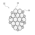
[Fig. 2] Fig. 2 is a diagram schematically showing an assembled particle according to an embodiment.
[Fig. 3] Fig. 3 is a diagram schematically showing a binder coat layer according to an embodiment. [Fig.
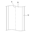
[Fig. 4] Fig. 4 is a view showing a cut portion of a current collector and an active material layer according to an embodiment. [Fig.
[Fig. 5] Fig. 5 is a diagram schematically showing a binder coat layer according to an embodiment.
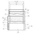
[Fig. 6] Fig. 6 is a diagram schematically showing a lithium ion secondary battery according to an embodiment. [Fig.
[Fig. 7] Fig. 7 is a view for explaining a wound electrode body according to an embodiment.
[Fig. 8] Fig. 8 is an SEM image of the positive electrode active material layer according to the comparative example taken from above.
9 is an SEM image of the positive electrode active material layer according to the embodiment taken from above; FIG.
10 is an SEM image of the positive electrode active material layer according to the comparative example taken from above.
이하, 여기서 제안되는 리튬 이온 2차 전지용 전극의 제조 방법에 대한 일 실시형태를 설명한다. 여기서 설명되는 실시형태는, 당연히 특히 본 발명을 한정하는 것을 의도한 것은 아니다. 또, 각 도면은 모식적으로 그려지고 있으며, 예를 들어, 각 도면에 있어서의 치수 관계(길이, 폭, 두께 등)는 실제의 치수 관계를 반영하는 것은 아니다. 또한, 본 명세서에 있어서 「2차 전지」란, 반복 충전 가능한 전지 일반을 말한다. 「리튬 이온 2차 전지」는, 전해질 이온으로서 리튬 이온을 이용하고, 정부극 사이에서 리튬 이온에 수반되는 전하의 이동에 의해 충방전이 실현되는 2차 전지를 말한다.Hereinafter, one embodiment of a method of manufacturing an electrode for a lithium ion secondary battery proposed here will be described. The embodiments described herein are, of course, not intended to limit the invention in any way. For example, the dimensional relationships (length, width, thickness, and the like) in the respective drawings do not reflect actual dimensional relationships. In the present specification, the term " secondary battery " refers to a battery capable of being repeatedly charged. A " lithium ion secondary battery " refers to a secondary battery in which lithium ions are used as electrolyte ions, and charging and discharging are realized by movement of electric charges accompanied by lithium ions between the positive electrodes.
<제1 실시형태>≪ First Embodiment >
여기서 개시되는 제조 방법은, 장척상의 집전체 상에 활물질층이 유지된 구조를 갖는 전극(정극 및 부극)을 제조하는 방법이다. 도 1은, 본 발명의 일 실시형태에 관련된 전극의 제조 공정을 구현화하는 제조 장치(10)를 나타내는 모식도이다. 이러한 제조 장치(10)는, 정극 형성 공정 및 부극 형성 공정의 쌍방에 이용될 수 있다. 여기서, 제조 장치(10)는, 도 1에 나타내는 바와 같이, 반송부(22)와, 바인더액 도공부(21)와, 조립 입자 공급부(24)와, 스퀴지 부재(25)와, 압연 롤러(26, 27)를 구비하고 있다. 여기서, 반송부(22)는 집전체(12)를 반송하는 장치이다. 바인더액 도공부(21)는, 바인더액(21a)을 도공하는 장치이다. 조립 입자 공급부(24)는, 조립 입자(32)를 공급하는 장치이다. 제조 장치(10)를 구성하는 이들의 장치에 대해서는, 후술한다. 도 2는, 조립 입자(32)를 모식적으로 나타내는 도면이다.The manufacturing method disclosed here is a method of manufacturing electrodes (positive electrode and negative electrode) having a structure in which an active material layer is held on a long-length current collector. 1 is a schematic diagram showing a
본 실시형태에 관련된 전극 제조 공정은, 이하의 공정 (a)~(e)를 포함하고 있다.The electrode manufacturing process according to the present embodiment includes the following steps (a) to (e).
(a) 바인더 코트층의 형성 공정(a) Process for forming a binder coat layer
(b) 조립 입자의 공급 공정(b) Feeding process of granulated particles
(c) 평탄화 공정(c) planarization process
(d) 프레스 공정(d) Pressing process
(e) 절단 공정(e) Cutting process
<a. 바인더 코트층의 형성 공정><A. Formation step of binder coat layer >
공정 a에서는, 장척상의 집전체(12) 상에 그 집전체(12)의 길이 방향을 따라 바인더와 용매를 포함하는 바인더액(21a)을 도공해 바인더 코트층(16)을 형성한다.In the step a, a
집전체(12)는, 전극(정극 및 부극)에 있어서 전기가 취출되는 부재이다. 예를 들어, 리튬 이온 2차 전지에 사용되는 집전체(12)에는, 전자 전도성이 우수하고, 전지 내부에서 안정적으로 존재하는 재료가 사용된다. 또, 경량화나 필요한 기계 강도나 가공 용이성 등이 요구된다. 예를 들어, 도 1에 나타내는 예에서는, 집전체(12)로서 띠 형상의 금속박이 준비되어 있다. 여기서는, 집전박으로서의 띠 형상의 금속박은, 권심(卷芯)에 감겨진 상태로 준비되어 있다. The
리튬 이온 2차 전지의 정극을 형성하는 경우, 예를 들어, 정극 집전체로서 알루미늄 또는 알루미늄 합금이 사용된다. 정극 집전체의 두께는 특별히 한정되지 않지만, 고강도 및 저저항의 관점에서, 대체로 5μm~30μm가 적당하고, 바람직하게는 10μm~20μm(예를 들어 15μm)이다. 리튬 이온 2차 전지의 부극을 형성하는 경우, 예를 들어, 부극 집전체로서 구리 또는 구리 합금이 사용된다. 부극 집전체의 두께로서는, 특별히 한정되지 않지만, 고강도 및 저저항의 관점에서, 대체로 6μm~20μm가 적당하고, 바람직하게는 8μm~15μm(예를 들어 10μm)이다. In the case of forming the positive electrode of the lithium ion secondary battery, for example, aluminum or an aluminum alloy is used as the positive electrode collector. Although the thickness of the positive electrode current collector is not particularly limited, it is suitably 5 m to 30 m, preferably 10 m to 20 m (for example, 15 m) from the viewpoint of high strength and low resistance. In the case of forming the negative electrode of the lithium ion secondary battery, for example, copper or a copper alloy is used as the negative electrode collector. The thickness of the negative electrode current collector is not particularly limited, but is suitably from 6 탆 to 20 탆, preferably from 8 탆 to 15 탆 (for example, 10 탆) from the viewpoint of high strength and low resistance.
도 1에 나타내어진 제조 장치(10)는, 상술한 띠 형상의 집전체(12)를 길이 방향을 따라 반송한다. 여기서는, 장척상의 집전체(금속박)(12)가, 반송부(22)에 의해, 미리 정해진 반송 경로를 따라 반송된다. 도면 내의 화살표(F)는, 반송 방향을 나타내고 있다. 이 실시형태에서는, 반송부(22)는, 복수의 반송 롤러(22)를 구비하고 있다. 장척상의 집전체(12)는, 도 1에 나타내는 바와 같이, 롤투롤에 의해 권출부(28a)로부터 권출되어, 복수의 반송 롤러(22)로 반송되면서 소정의 처리가 가해지고, 권취부(28b)로 권취된다. The
바인더액(21a)은, 용매에 바인더를 분산 또는 용해시킨 액이다. 바인더액(21a)의 용매로서는, 환경 부하를 경감한다는 관점에서, 이른바 수계의 용매가 호적하게 사용된다. 이 경우, 물 또는 물을 주체로 하는 혼합 용매가 사용된다. 이러한 혼합 용매를 구성하는 물 이외의 용매 성분으로서는, 물과 균일하게 혼합될 수 있는 유기 용매(저급 알코올, 저급 케톤 등)의 1종 또는 2종 이상을 임의 선택해서 사용할 수 있다. 예를 들어, 그 수계 용매의 80 질량% 이상(보다 바람직하게는 90 질량% 이상, 더욱 바람직하게는 95 질량% 이상)이 물인 수계 용매의 사용이 바람직하다. 특히 바람직한 예로서, 실질적으로 물로 이루어지는 수계 용매를 들 수 있다. 또, 바인더액(21a)의 용매는, 이른바 수계 용매로 한정되지 않고, 이른바 유기 용제계여도 된다. 유기 용제계로서는, 예를 들어 N-메틸피롤리돈(NMP) 등을 들 수 있다.The
또, 바인더액(21a)에 포함되는 바인더로서는, 사용하는 용매에 분산 또는 용해될 수 있는 폴리머 재료를 사용하는 것이 바람직하다. 이러한 바인더(제1 바인더)는, 예를 들어 조립 입자(32)의 제작에 사용하는 것과 동일해도 되고, 상이해도 된다. 일례로서, 예를 들어 용매가 수계인 경우, 예를 들어, 스티렌부타디엔 고무(SBR), 폴리아크릴산(PAA) 등의 사용이 바람직하다. 또, 용매로서 유기 용제계를 사용하는 경우, 바인더로서 예를 들어, 폴리불화비닐리덴(PVDF), 폴리아크릴산(PAA) 등을 바람직하게 사용할 수 있다. 바인더액(21a)의 호적 예로서는, 예를 들어, 리튬 이온 2차 전지의 정극에서는, 물을 용매로 하고, 바인더로서의 SBR이나 아크릴 수지(예를 들어, 폴리메타크릴산에스테르 수지)를 혼합하면 된다. 또, 리튬 이온 2차 전지의 부극에서는, 물을 용매로 하고, 바인더로서의 SBR을 혼합하면 된다.As the binder contained in the
바인더액(21a)의 고형분율로서는, 취급성이나 도공성을 높이는 관점에서, 대체로 20 질량%~60 질량%, 바람직하게는 30 질량%~50 질량%이면 된다.The solid content of the
이 실시형태에서는, 바인더액(21a)은, 예를 들어, 장척상의 집전체(12)의 길이 방향을 따라 미리 정해진 도공 패턴으로 집전체(12)에 도공된다. 여기서는, 집전체(12)에 미리 정해진 영역에 바인더액(21a)이 도포된다. 바인더액(21a)은, 예를 들어, 그라비아 인쇄 등으로 도공하면 된다. 예를 들어, 바인더액 도공부(21)에는, 다이렉트 그라비아 롤코터(direct gravure roll coater)가 사용될 수 있다. 이러한 바인더액 도공부(21)에서는, 소정의 패턴 형상이 표면에 조각된 그라비아 롤(21b)을 사용한 다이렉트 그라비아에 의해, 바인더액(21a)이 집전체(12)에 전사된다. 도 1에 나타내는 예에서는, 반송부(22)에 있어서, 바인더액(21a)이 도공되는 처리면(활물질층이 형성되는 면)을 아래를 향하게 하고, 띠 형상의 집전체(12)를 반송해서, 당해 집전체(12)에 그라비아 롤(21b)을 닿게 한다. 그라비아 롤(21b)의 아래측은, 저류조(21c)에 담긴 바인더액(21a)에 잠겨 있다. 또, 그라비아 롤(21b)이 집전체(12)에 닿는 면의 뒤쪽에는 백 롤러(21d)가 닿게 되어 있다. 이로써, 저류조(21c)에 담긴 바인더액(21a)은, 그라비아 롤(21b)을 통해 집전체(12)에 연속해서 전사된다. 이러한 전사에 의해, 집전체(12) 상에 그라비아 롤(21b)의 패턴 형상에 대응하는 바인더 코트층(16)이 형성된다.In this embodiment, the
바인더 코트층(16)의 두께로서는, 특별히 한정되지 않지만, 집전체(12)와 활물질층(14)의 접착성을 높이는 관점에서, 예를 들어 1μm 이상, 바람직하게는 2μm 이상의 두께로 하면 된다. 또, 저항을 저감시키는 관점에서는, 예를 들어 10μm 이하, 바람직하게는 5μm 이하의 두께로 하면 된다.The thickness of the
도 3은, 집전체(12) 상에 형성된 바인더 코트층(16)을 모식적으로 나타내고 있다. 이 실시형태에서는, 바인더 코트층(16)은, 도 3에 나타내는 바와 같이, 바인더액이 도공되어 이루어지는 띠 형상(폭이 좁은 선 형상도 포함할 수 있다. 이하, 같다.)의 도공부(16a)와, 바인더액이 도공되어 있지 않은 띠 형상의 미도공부(16b)가 교대로 인접하도록, 집전체(12) 상에 간헐적으로 형성된다. 여기서는, 띠 형상의 도공부(16a)는, 집전체(12)의 폭 방향에 대해 비스듬하게 연장되는 복수의 선(가상선)(L1)을 따라 형성되어 있다. 또, 띠 형상의 도공부(16a)는, 당해 복수의 선(L1)을 따라, 일정한 간격을 두고(파선 형상으로) 형성되어 있다.Fig. 3 schematically shows the
여기서, 바인더 코트층(16)은, 집전체(12)의 길이 방향과 직교하는 폭 방향에 있어서, 바인더액의 단위면적당 도공량(고형분 환산)이 상대적으로 많은 다량 코트 영역(18A)과, 바인더액의 단위면적당 도공량(고형분 환산)이 상대적으로 적은 소량 코트 영역(18B)을 갖도록 형성되어 있다. 이 실시형태에서는, 다량 코트 영역(18A)은, 바인더 코트층(16)의 폭 방향에 있어서의 양측의 단부(16E)에 형성되어 있다. 이하, 바인더 코트층(16)의 양측의 단부(16E)에 형성된 다량 코트 영역을, 임의로, 제1 다량 코트 영역(18A)이라고 칭한다. 또, 소량 코트 영역(18B)은, 바인더 코트층(16)의 다량 코트 영역(18A)을 제외한 부위(16C)에 형성되어 있다. 이와 같이, 바인더 코트층(16)의 양측의 단부(16E)에, 바인더액의 도공량이 상대적으로 많은 제1 다량 코트 영역(18A)을 형성함으로써, 프레스 공정 후에 활물질층의 단부에서 박리가 생기거나 활물질이 활락(가루 떨어짐)하거나 하는 현상이 완화될 수 있다.Here, the
제1 다량 코트 영역(18A)의 도공량으로서는, 소량 코트 영역(18B)의 도공량보다 많으면 된다. 예를 들어, 제1 다량 코트 영역(18A)의 도공량으로서는, 대략 0.05mg/cm2 이상(예를 들어 0.05mg/cm2~0.2mg/cm2)으로 하는 것이 적당하고, 바람직하게는 0.1mg/cm2 이상(예를 들어 0.1mg/cm2~0.2mg/cm2)이다. 이와 같은 제1 다량 코트 영역(18A)의 도공량 범위 내이면, 활물질층 단부에서의 가루 떨어짐을 보다 양호하게 억제할 수 있다. 또, 소량 코트 영역(18B)의 도공량으로서는, 제1 다량 코트 영역(18A)의 도공량보다 적으면 된다. 예를 들어, 소량 코트 영역(18B)의 도공량으로서는, 대략 0.04mg/cm2 이하(예를 들어 0.02mg/cm2~0.04mg/cm2)로 하는 것이 적당하고, 바람직하게는 0.03mg/cm2 이하(예를 들어 0.02mg/cm2~0.03mg/cm2)이다. 이와 같은 소량 코트 영역(18B)의 도공량 범위 내이면, 저항을 과도하게 증대시키지 않고, 집전체(12)와 활물질층의 접착성을 높일 수 있다. 예를 들어, 제1 다량 코트 영역(18A)의 도공량 A와 소량 코트 영역(18B)의 도공량 B가, A≥1.25B의 관계를 만족하는 것이 바람직하고, A≥3B의 관계를 만족하는 것이 보다 바람직하며, A=5B의 관계를 만족하는 것이 더욱 바람직하다.The coating amount of the first large-
본 실시형태에 관련된 바인더 코트층(16)으로서는, 도 3에 나타내는 바와 같이, 제1 다량 코트 영역(18A)의 폭(폭 방향의 길이)(H1)이 1mm 이상인 것이 적당하다. 제1 다량 코트 영역(18A)의 폭(H1)이 1mm 이상이면, 활물질층 단부에서의 가루 떨어짐을 보다 양호하게 억제할 수 있다. 본 실시형태에 관련된 바인더 코트층(16)으로서는, 제1 다량 코트 영역(18A)의 폭(H1)이 2.5mm 이상인 것이 바람직하고, 3mm 이상인 것이 보다 바람직하다. 그 한편으로, 제1 다량 코트 영역(18A)의 폭(H1)이 너무 넓으면, 집전체와 활물질층의 계면에 존재하는 바인더가 증가하기 때문에, 전극 저항이 증대하는 경향이 될 수 있다. 저항 증대를 방지하는 관점에서는, 대체로 10mm 이하가 바람직하고, 8mm 이하가 보다 바람직하다. 예를 들어, 제1 다량 코트 영역(18A)의 폭(H1)이 1mm 이상 10mm 이하(나아가서는 2mm 이상 5mm 이하)의 바인더 코트층(16)이, 가루 떨어짐 방지와 저저항을 양립한다는 관점에서 적당하다.As the
제1 다량 코트 영역(18A) 및 소량 코트 영역(18B)의 도공량은, 예를 들어, 도공부(16a) 및 미도공부(16b)의 라인 폭이나, 도공부(16a)의 두께(높이)를 변경시킴으로써 임의 조정할 수 있다. 이 실시형태에서는, 제1 다량 코트 영역(18A)은, 소량 코트 영역(18B)보다 미도공부(16b)의 폭(도공부(16a) 사이의 피치)이 좁다. 바꾸어 말하면, 제1 다량 코트 영역(18A)은, 소량 코트 영역(18B)보다 집전체(12)의 노출 면적비율이 작다. 바람직한 일 양태에서는, 제1 다량 코트 영역(18A)에 있어서의 집전체(12)의 노출 면적 비율은, 대체로 20% 미만(바람직하게는 10% 이하, 예를 들어 0%~5%)일 수 있다. 바람직한 일 양태에서는, 제1 다량 코트 영역(18A)의 전면에 바인더액이 도공될 수 있다(즉 노출 면적비율 0%). 또, 소량 코트 영역(18B)에 있어서의 집전체(12)의 노출 면적 비율은, 대체로 20% 이상(바람직하게는 25% 이상, 예를 들어 20%~30%)일 수 있다.The coating amount of the first
또, 제1 다량 코트 영역(18A)의 도공량은, 띠 형상의 도공부(16a)와는 상이한 도공부(16a1, 16a2)를 별도 형성함으로써, 소량 코트 영역(18B)보다 늘려도 된다. 도 3에 나타낸 예에서는, 제1 다량 코트 영역(18A)의 폭 방향의 양측의 가장자리에, 파선 형상의 도공부(16a1, 16a2)가 집전체(12)의 길이 방향을 따라 형성되어 있다. 이와 같이 제1 다량 코트 영역(18A)의 폭 방향의 양측의 가장자리에 도공부(16a1, 16a2)를 형성함으로써, 상술한 가루 떨어짐 방지 효과가 보다 양호하게 발휘될 수 있다.The amount of coating of the first large
<b. 조립 입자의 공급 공정><B. Feeding Process of Assembled Particles>
공정 b에서는, 도 1에 나타내는 바와 같이, 상기 바인더 코트층(16) 위에 조립 입자(32)를 공급한다. 도 1에 나타내는 예에서는, 집전체(12)는, 반송 롤러(22)를 따라 회전되어, 바인더 코트층(16)이 형성된 면을 위를 향하게 하여 조립 입자 공급부(24)까지 반송된다. 이 조립 입자 공급부(24)에 의해, 조립 입자(32)가 공급된다. In step b, the
여기서 공급되는 조립 입자(32)는, 도 2에 나타내는 바와 같이, 활물질 입자(34)와 바인더(36)(제2 바인더)를 적어도 포함하고 있다. 이러한 조립 입자(32)는, 개개의 활물질 입자(34)의 표면에 바인더(36)가 부착되고, 나아가 그 활물질 입자(34)가 바인더(36)에 의해 서로 결합된 양태일 수 있다. 호적한 일 양태에서는, 바인더(36)가 활물질 입자(34)의 내부 및 외표면에 국소적으로 편재하지 않고 거의 균일하게 분산되어 배치되어 있다. 조립 입자(32)는, 활물질 입자(34) 및 바인더(36) 이외의 재료가 포함되어 있어도 되고, 예를 들어, 도전재나 증점재가 포함되어 있어도 된다.As shown in Fig. 2, the
조립 입자의 성상으로서는, 예를 들어, 평균 입경 R이 대략 50μm 이상이면 된다. 균질한 활물질층을 형성하는 관점에서, 조립 입자의 평균 입경 R은, 바람직하게는 60μm 이상, 보다 바람직하게는 70μm 이상, 더욱 바람직하게는 75μm 이상이다. 또, 조립 입자의 평균 입경 R은, 대체로 120μm 이하, 예를 들어 100μm 이하이다. 여기서 개시되는 기술은, 예를 들어, 조립 입자의 평균 입경이 50μm 이상 120μm 이하인 양태에서 바람직하게 실시될 수 있다.The shape of the granulated particles may be, for example, an average particle diameter R of about 50 탆 or more. From the viewpoint of forming a homogeneous active material layer, the mean particle diameter R of the granulated particles is preferably 60 占 퐉 or more, more preferably 70 占 퐉 or more, and further preferably 75 占 퐉 or more. The average particle diameter R of the granulated particles is generally 120 占 퐉 or less, for example, 100 占 퐉 or less. The technique disclosed here can be preferably carried out, for example, in an embodiment in which the average particle diameter of the granulated particles is 50 μm or more and 120 μm or less.
또한, 본 명세서 중에 있어서 「평균 입경」이란, 특기하지 않는 한, 레이저 산란·회절법에 근거하는 입도 분포 측정 장치에 기초하여 측정한 입도 분포에 있어서의 적산치 50%에서의 입경, 즉 50% 체적 평균 입자경을 의미하는 것으로 한다. 여기서, 적산치 50%에서의 입경, 즉 50% 체적 평균 입자경을 임의로 「D50」이라고 칭한다. 보다 구체적으로는, 레이저 회절·산란식 입도 분포 측정 장치(예를 들어, 「마이크로트랙 MT-3200II」, 닛키소주식회사제)를 사용하고, 압축 공기에 의한 입자 분산은 실시하지 않고, 건식 측정한 50% 체적 평균 입자경이다.In the present specification, " average particle size " means a particle size at an integrated value of 50% in a particle size distribution measured based on a particle size distribution measurement apparatus based on a laser scattering / diffraction method, Mean volume average particle diameter. Here, the particle diameter at the integrated value of 50%, that is, the 50% volume average particle diameter is arbitrarily referred to as " D50 ". More specifically, using a laser diffraction / scattering type particle size distribution measuring apparatus (e.g., " Microtrack MT-3200II ", manufactured by Nikkiso Co., Ltd.), particle dispersion by compressed air is not carried out, 50% volume average particle size.
이러한 조립 입자(32)는, 예를 들어, 활물질 입자(34)와 바인더(36)를 소정의 비율로 혼합하여, 조립, 분급 등을 실시함으로써 준비할 수 있다. 조립 수법으로서는 특별히 제한은 없고, 예를 들어, 전동 조립법, 유동층 조립법, 교반 조립법, 압축 조립법, 압출 조립법, 파쇄 조립법, 스프레이 드라이법(분무 조립법) 등을 채용할 수 있다. 하나의 호적 예로는, 활물질 입자(34)와 바인더(36)를 용매에 혼합시킨 합제(현탁액)를, 스프레이 드라이법으로 조립한다. 스프레이 드라이법에서는, 합제가 건조 분위기 중에 분무된다. 이 때, 분무되는 액적에 포함되는 입자가 대체로 1개의 덩어리로 되어 조립된다. 이 때문에, 액적의 크기에 따라, 조립 입자(32)에 포함되는 고형분량이 변하고, 조립 입자(32)의 크기나 질량 등이 변한다. 분무되는 액적에는, 활물질 입자(34)와 바인더(36)가 적어도 포함되어 있으면 된다. 또 분무되는 액적에는, 예를 들어, 도전재나 증점재가 포함되어 있어도 된다.Such an assembled
리튬 이온 2차 전지의 정극을 형성하는 경우, 정극 활물질 입자로서는, 종래부터 리튬 이온 2차 전지의 정극 활물질로서 사용되고 있는 각종 재료를 특별히 한정 없이 사용할 수 있다. 호적 예로서, 리튬니켈 산화물(예를 들어 LiNiO2), 리튬코발트 산화물(예를 들어 LiCoO2), 리튬망간 산화물(예를 들어 LiMn2O4) 등의 리튬과 천이금속원소를 구성금속원소로서 포함하는 산화물(리튬천이금속 산화물)이나, 인산망간리튬(LiMnPO4), 인산철리튬(LiFePO4) 등의 리튬과 천이금속원소를 구성금속원소로서 포함하는 인산염 등을 들 수 있다. 정극 활물질 입자의 평균 입경(D50)은 특별히 한정되지 않지만, 대체로 1μm~10μm 정도가 적당하고, 바람직하게는 4μm~6μm이다.In the case of forming the positive electrode of the lithium ion secondary battery, various materials conventionally used as the positive electrode active material of the lithium ion secondary battery can be used as the positive electrode active material particles without particular limitation. For example, lithium and a transition metal element such as lithium nickel oxide (for example, LiNiO 2 ), lithium cobalt oxide (for example, LiCoO 2 ), lithium manganese oxide (for example, LiMn 2 O 4 ) (Lithium transition metal oxide), lithium phosphate such as lithium manganese lithium (LiMnPO 4 ) and lithium iron phosphate (LiFePO 4 ), and phosphates containing a transition metal element as a constituent metal element. The average particle diameter (D50) of the positive electrode active material particles is not particularly limited, but is suitably about 1 to 10 mu m, preferably 4 to 6 mu m.
리튬 이온 2차 전지의 부극을 형성하는 경우, 부극 활물질 입자로서는, 종래부터 리튬 이온 2차 전지의 부극 활물질로서 사용되고 있는 각종의 재료를 특별히 한정 없이 사용할 수 있다. 호적 예로서, 그라파이트 카본, 아몰퍼스 카본 등의 탄소계 재료, 티탄산리튬 등의 리튬천이금속 산화물, 리튬천이금속 질화물, 실리콘 화합물 등을 들 수 있다. 부극 활물질 입자의 평균 입경(D50)은 특별히 한정되지 않지만, 대체로 10μm~30μm 정도가 적당하고, 바람직하게는 15μm~25μm이다.In the case of forming the negative electrode of the lithium ion secondary battery, various materials conventionally used as the negative electrode active material of the lithium ion secondary battery can be used as the negative electrode active material particle without particular limitation. Examples of the host material include carbon-based materials such as graphite carbon and amorphous carbon, lithium transition metal oxides such as lithium titanate, lithium transition metal nitrides, silicon compounds and the like. The average particle diameter (D50) of the negative electrode active material particles is not particularly limited, but is suitably about 10 mu m to 30 mu m, preferably 15 mu m to 25 mu m.
조립 입자(32)에 포함시키는 바인더(36)로서는, 활물질의 결합을 실현할 수 있는 각종 재료 중에서 채용하는 조립 방법에 알맞은 재료를 선택·사용하면 된다. 일례로서, 습식 조립 방법(예를 들어 상기 스프레이 드라이법)을 채용하는 경우에는, 용매에 용해 또는 분산 가능한 폴리머가 사용된다. 수성 용매에 용해 또는 분산 가능한 폴리머로서는, 예를 들어, 아크릴레이트 중합체, 고무류(스티렌부타디엔 공중합체(SBR), 아크릴산 변성 SBR수지(SBR계 라텍스) 등), 아세트산비닐 공중합체 등을 들 수 있다. 또, 비수용매에 용해 또는 분산 가능한 폴리머로서는, 예를 들어, 폴리불화비닐리덴(PVDF)을 들 수 있다. 또, 조립 입자(32)에 포함시키는 바인더(36)로서 셀룰로오스계 폴리머, 불소계 수지(예를 들어, 폴리테트라플루오로에틸렌(PTFE)) 등을 사용해도 된다.As the
또, 도전재를 포함하는 구성에 있어서는, 도전재로서 예를 들어, 카본 분말, 카본 파이버 등의 카본 재료가 예시된다. 이와 같은 도전재로부터 선택되는 1종을 단독으로 사용해도 되고 2종 이상을 병용해도 된다. 카본 분말로서는, 예를 들어, 아세틸렌 블랙(AB), 오일 퍼네이스 블랙, 흑연화 카본 블랙, 카본 블랙, 케첸 블랙, 그라파이트 등의 분말을 사용할 수 있다. 이러한 도전재는, 활물질 입자(34)와 집전체(12)의 도전 패스를 형성하는데 있어서, 도전성이 부족한 활물질 입자(34)를 사용하는 경우에 호적하게 첨가된다.In the constitution including the conductive material, carbon materials such as carbon powder, carbon fiber and the like are exemplified as the conductive material. One kind selected from such conductive materials may be used alone, or two or more types may be used in combination. As the carbon powder, powders such as acetylene black (AB), oil black, graphitized carbon black, carbon black, Ketjen black, graphite and the like can be used. Such a conductive material is suitably added when the
또, 증점제를 포함하는 구성에 있어서는, 증점제로서 예를 들어, 카르복시메틸셀룰로오스(CMC), CMC의 나트륨염(CMC-Na), 폴리비닐알코올(PVA), 에틸렌비닐알코올 공중합체(EVOH) 등의 재료가 예시된다. 이와 같은 증점제로부터 선택되는 1종을 단독으로 사용해도 되고 2종 이상을 병용해도 된다. In the constitution including the thickening agent, for example, a thickener such as carboxymethylcellulose (CMC), sodium salt of CMC (CMC-Na), polyvinyl alcohol (PVA), ethylene vinyl alcohol copolymer Materials are exemplified. One kind selected from such thickening agents may be used alone, or two or more kinds may be used in combination.
조립 입자 공급부(24)는, 반송부(22)에 의해 반송되는 집전체(12) 상에 형성된 바인더 코트층 위에 조립 입자(32)를 공급한다. 여기서는, 조립 입자 공급부(24)는, 조립 입자(32)를 저류(貯留)하는 호퍼를 구비하고 있다. 호퍼는, 도시는 생략하지만, 조립 입자(32)를 공급하는 양을 조정하는 조정 장치를 구비하고 있으면 좋다. 이 경우, 호퍼는, 예를 들어, 집전체(12)의 반송 속도 등에 따라 조립 입자(32)의 공급량을 조정해서, 적당한 양의 조립 입자(32)를 습윤 상태의 바인더 코트층(16) 위에 공급하면 좋다. 여기서는, 조립 입자(32)는, 복수의 조립 입자(32)가 모인 집적물(분체)(30)로서 공급된다.The assembled
<c. 평탄화 공정><C. Planarization process>
공정 c에서는, 도 1에 나타내는 바와 같이, 바인더 코트층(16) 위에 공급된 조립 입자(32)에 스퀴지 부재(25)를 닿게 해서 평탄화한다. 이러한 공정에서는, 예를 들어, 바인더 코트층(16) 위에 공급된 조립 입자(32)의 두께(요컨대, 조립 입자(32)의 집적물(30)의 두께)가 균일하게 조정된다. 이 실시형태에서는, 조립 입자 공급부(24)의 하류측(집전체의 반송 경로에 있어서의 하류측)에 스퀴지 부재(25)가 설치되어 있다. 스퀴지 부재(25)는, 바인더 코트층(16) 위에 공급된 조립 입자(32)의 두께를 조정한다. 예를 들어, 스퀴지 부재(25)와 반송되는 집전체(12)의 사이에는 간극이 있고, 이러한 간극에 따라 통과하는 조립 입자(32)의 두께가 조정된다. 이 실시형태에서는, 스퀴지 부재(25)는, 집전체(12) 상에 공급된 조립 입자(32)를, 두께 방향으로 사이에 끼우도록 배치된 롤러 스퀴지(25a)와, 백 롤러(27)(압연 롤러(27)로서도 기능 한다.)로 구성되어 있다. 또한, 여기서는, 롤러 스퀴지(25a)는, 롤 형상의 부재이지만, 블레이드 형상의 부재여도 된다. 롤러 스퀴지(25a)와 집전체(12)의 간극은, 조립 입자(32)의 입경 및 목부량(目付量)에 좌우되지만, 예를 들어, 대략 100μm~300μm 정도(호적 예로서는, 대략 150μm~250μm 정도)로 조정하면 된다.In step c, as shown in Fig. 1, the
<d. 프레스 공정><D. Pressing process>
공정 d에서는, 바인더 코트층(16) 위에 공급한 조립 입자(32)를 프레스(압연)함으로써, 집전체(12) 상에 활물질층(14)을 형성한다. 이 실시형태에서는, 압연 롤러(26, 27)는, 띠 형상의 집전체(12)가 반송되는 반송 경로에 있어서, 조립 입자(32)와 집전체(12)를 사이에 끼우는 부재이다. 이 경우, 집전체(12)에 퇴적시키는 조립 입자(32)의 두께를 고려해서, 압연 롤러(26, 27)의 간극을 조정하면 된다. 이로써, 적당한 강도로 조립 입자(32)가 바인더 코트층(16)을 개재하여 집전체(12)에 압착되고, 집전체(12) 상에 고착된다. 동시에, 조립 입자(32) 중에서 바인더(36)의 접촉 개소가 증가해, 조립 입자(32)끼리가 서로 밀착된다. 이로써, 집전체(12)의 표면에 활물질 입자(34)를 포함하는 층(활물질층(14))이 대략 일정한 두께로 성형된다. 그 때, 도 1~도 3에 나타내는 바와 같이, 바인더 코트층(16)의 양측의 단부(16E)에 형성된 제1 다량 코트 영역(18A)에서는, 단위면적당 바인더액의 도공량이 상대적으로 많기 때문에, 조립 입자(32)가 집전체(12) 상에 강하게 고착된다. 또, 제1 다량 코트 영역(18A)에서는, 바인더액의 도공량이 많은 만큼, 활물질층(14)이 촘촘하게(고밀도로) 형성된다. 그 때문에, 조립 입자(32) 중에서 바인더(36)의 접촉 개소가 더욱 증가해서, 조립 입자(32)끼리가 강하게 밀착한다. 이에 의해, 프레스 후에 활물질층(14)의 단부에서 박리가 생기거나 활물질이 활락하거나 하는 현상이 완화될 수 있다.In step d, the
<e. 절단 공정><E. Cutting process>
공정 e에서는, 활물질층(14)을 형성한 후, 도시되지 않은 절단 장치에 의해 집전체(12) 및 활물질층(14)을 폭 방향의 중앙부에서 길이 방향을 따라 절단하는 것으로, 2매의 전극 시트로 분할한다. 여기서 도 4 중의 일점쇄선은, 집전체(12) 및 활물질층(14)이 절단되는 절단 개소(즉 슬릿을 형성하는 위치)(P)를 나타내고 있다. 분할된 2매의 전극 시트는, 각각 다음 공정에 제공된다. 이와 같이 해서, 집전체(12) 상에 활물질층(14)이 유지된 구조를 갖는 리튬 이온 2차 전지용 전극이 제조될 수 있다.In Step e, after the
이상, 본 발명의 일 실시형태에 관련된 리튬 이온 2차 전지용 전극의 제조 방법에 대해 설명했다. 다음으로, 본 발명의 다른 일 실시형태에 관련된 리튬 이온 2차 전지용 전극의 제조 방법에 대해 설명한다.The manufacturing method of the electrode for a lithium ion secondary battery according to one embodiment of the present invention has been described above. Next, a method of manufacturing an electrode for a lithium ion secondary battery according to another embodiment of the present invention will be described.
<제2 실시형태>≪ Second Embodiment >
제2 실시형태에 관련된 리튬 이온 2차 전지용 전극의 제조 방법은, 상술한 제1 실시형태와 같이, 이하의 공정을 포함하고 있다.The manufacturing method of the electrode for a lithium ion secondary battery according to the second embodiment includes the following steps as in the first embodiment described above.
(a) 바인더 코트층의 형성 공정(a) Process for forming a binder coat layer
(b) 조립 입자의 공급 공정(b) Feeding process of granulated particles
(c) 평탄화 공정(c) planarization process
(d) 프레스 공정(d) Pressing process
(e) 절단 공정(e) Cutting process
여기서 도 5는, 제2 실시형태의 바인더 코트층의 형성 공정 a에 있어서, 집전체(12) 상에 형성된 바인더 코트층(16)을 모식적으로 나타내고 있다. 도 5 중의 일점쇄선은, 절단 공정 e에 있어서 절단이 예정되어 있는 절단 개소(P)를 나타내고 있다. 제2 실시형태에서는, 도 5에 나타내는 바와 같이, 바인더액의 도공량이 상대적으로 많은 다량 코트 영역이, 바인더 코트층(16)의 양측의 단부(16E)(제1 다량 코트 영역(18A))에 더해, 상기 절단 공정 e에 있어서 절단이 예정되어 있는 절단 개소(P)에 형성되는 점에서, 상술한 제1 실시형태와는 다르다. 이하, 절단 개소(P)에 형성된 다량 코트 영역을, 임의로, 제2 다량 코트 영역(18C)이라고 칭한다. 또한, 그 밖의 형태에 대해서는, 제1 실시형태와 동일하기 때문에, 중복된 설명은 생략한다.5 schematically shows the
제2 실시형태에 관련된 제조 방법은, 활물질층을 형성한 후, 활물질층 및 집전체를 폭 방향의 중앙부에서 길이 방향을 따라 절단하는 공정을 포함한다. 이러한 절단 공정 e에서는, 절단시에 활물질층에 큰 스트레스가 가해지기 때문에, 당해 절단 개소에서 활물질층(14)이 박리되거나 활물질이 활락하거나 하기 쉬워진다. 특히, 바인더 코트층(16)을 간헐적으로 형성했을 경우, 미도공부(16b)에서는 활물질층(14)과 집전체(12)의 밀착성이 약하기 때문에, 가루 떨어짐이 생기기 쉽다. The manufacturing method according to the second embodiment includes a step of cutting the active material layer and the current collector along the longitudinal direction at the central portion in the width direction after the active material layer is formed. In this cutting step e, since a large stress is applied to the active material layer at the time of cutting, the
이에 대하여, 상기 구성에 의하면, 절단 공정 e에 있어서 절단이 예정되어 있는 절단 개소(P)에, 바인더액의 도공량이 상대적으로 많은 제2 다량 코트 영역(18C)을 형성함으로써, 프레스 공정 시에 당해 절단 개소에 포함되는 조립 입자(32)가 집전체(12) 상에 강하게 고착된다. 또, 바인더의 도공량이 많은 만큼, 당해 절단 개소의 활물질층(14)이 촘촘하게(고밀도로) 형성된다. 그 때문에, 조립 입자(32) 중에서 바인더(36)의 접촉 개소가 더욱 증가해서 조립 입자(32)끼리가 강하게 밀착한다. 이것에 의해, 절단시에 절단 개소에서 활물질층(14)이 박리되거나 활물질이 활락하거나 하는 현상이 완화될 수 있다.On the other hand, according to the above-described configuration, the second large-
제2 다량 코트 영역(18C)의 도공량으로서는, 소량 코트 영역(18B)의 도공량보다 많으면 된다. 예를 들어, 제2 다량 코트 영역(18C)의 도공량으로서는, 대략 0.05mg/cm2 이상(예를 들어 0.05mg/cm2~0.2mg/cm2)으로 하는 것이 적당하고, 바람직하게는 0.1mg/cm2 이상(예를 들어 0.1mg/cm2~0.2mg/cm2)이다. 이와 같은 제2 다량 코트 영역(18C)의 도공량 범위 내이면, 절단 개소에서의 가루 떨어짐을 보다 양호하게 억제할 수 있다.The coating amount of the second large
본 실시형태에 관련된 바인더 코트층(16)으로서는, 도 5에 나타내는 바와 같이, 제2 다량 코트 영역(18C)의 폭(폭 방향의 길이)(H2)이 1mm 이상인 것이 적당하다. 제2 다량 코트 영역(18C)의 폭(H2)이 1mm 이상이면, 슬릿(틈)을 형성하는 절단 영역을 충분히 확보할 수 있다. 그 때문에, 반송 중의 집전체(12)가 폭 방향으로 위치가 어긋난 경우에도, 제2 다량 코트 영역(18C)에 슬릿을 확실하게 형성할 수 있다. 본 실시형태에 관련된 바인더 코트층(16)으로서는, 제2 다량 코트 영역(18C)의 폭(H2)이 2.5mm 이상인 것이 바람직하고, 3mm 이상인 것이 보다 바람직하다. 그 한편으로, 제2 다량 코트 영역(18C)의 폭(H2)이 너무 넓으면, 집전체와 활물질층의 계면에 존재하는 바인더가 증가하기 때문에, 전극 저항이 증대하는 경향이 될 수 있다. 저항 증대를 방지하는 관점에서는, 대체로 10mm 이하가 바람직하고, 8mm 이하가 보다 바람직하다.As the
제2 다량 코트 영역(18C)의 도공량은, 예를 들어, 도공부(16a) 및 미도공부(16b)의 라인 폭이나, 도공부(16a)의 두께(높이)를 변경시킴으로써 임의 조정할 수 있다. 이 실시형태에서는, 제2 다량 코트 영역(18C)은, 소량 코트 영역(18B)보다 미도공부(16b)의 폭(도공부(16a) 사이의 피치)이 좁다. 바꾸어 말하면, 제2 다량 코트 영역(18C)는, 소량 코트 영역(18B)보다 집전체(12)의 노출 면적비율이 작다. 바람직한 일 양태에서는, 제2 다량 코트 영역(18C)에 있어서의 집전체(12)의 노출 면적비율은, 대체로 10% 이하(바람직하게는 8% 이하, 보다 바람직하게는 5% 이하)일 수 있다. 바람직한 일 양태에서는, 제2 다량 코트 영역(18C)의 전면에 바인더액이 도공될 수 있다(즉 노출 면적비율 0%). 이와 같이 제2 다량 코트 영역(18C)에 있어서의 집전체(12)의 노출 면적비율을 적게 함으로써, 절단 개소에서의 가루 떨어짐을 효과적으로 회피할 수 있다.The amount of coating of the second large
또, 제2 다량 코트 영역(18C)의 도공량은, 띠 형상의 도공부(16a)와는 상이한 도공부(16a3, 16a4)를 별도 형성함으로써, 소량 코트 영역(18B)보다 늘려도 된다. 도 5에 나타낸 예에서는, 제2 다량 코트 영역(18C)의 폭 방향의 양측의 가장자리에, 파선 형상의 도공부(16a3, 16a4)가 집전체(12)의 길이 방향을 따라 형성되어 있다. 이와 같이 제2 다량 코트 영역(18C)의 폭 방향의 양측의 가장자리에 도공부(16a3, 16a4)를 형성함으로써, 상술한 가루 떨어짐 방지 효과가 보다 양호하게 발휘될 수 있다.The amount of coating of the second large
<리튬 이온 2차 전지>≪ Lithium ion secondary battery >
이하, 상술한 제조 장치(10)를 사용하여 형성된 부극(부극 시트) 및 정극(정극 시트)을 사용하여 구축되는 리튬 이온 2차 전지의 일 실시형태에 대해, 도 6 및 도 7에 나타내는 모식도를 참조하면서 설명한다. 도 6은 본 발명의 일 실시형태에 관련된 리튬 이온 2차 전지(100)의 단면도이다. 도 7은, 당해 리튬 이온 2차 전지(100)에 내장되는 전극체(40)를 나타내는 도이다. 이 리튬 이온 2차 전지(100)는, 정극(정극 시트)(50)으로서 상술한 제조 장치(10)를 사용하여 제조된 정극(정극 시트)(50)이 사용되고 있다. 또, 부극(부극 시트)(60)으로서 상술한 제조 장치(10)를 사용하여 제조된 부극(부극 시트)(60)이 사용되고 있다. Hereinafter, with reference to an embodiment of a lithium ion secondary battery constructed using a negative electrode (negative electrode sheet) and a positive electrode (positive electrode sheet) formed using the above-described
본 발명의 일 실시형태에 관련된 리튬 이온 2차 전지(100)는, 도 6에 나타내는 바와 같은 편평한 사각형의 전지 케이스(즉 외장 용기)(80)로 구성되어 있다. 리튬 이온 2차 전지(100)는, 도 6 및 도 7에 나타내는 바와 같이, 편평 형상의 권회 전극체(40)가, 액상 전해질(전해액)(85)과 함께, 전지 케이스(80)에 수용되어 있다.A lithium ion
전지 케이스(80)는, 한쪽 끝(전지(100)의 통상적인 사용 상태에 있어서의 상단부에 상당한다.)에 개구부를 갖는 상자 형상(즉 바닥이 있는 직육면체 형상)의 케이스 본체(81)와, 그 개구부에 장착되어 그 개구부를 막는 사각형상 플레이트 부재로 이루어지는 덮개체(봉구판)(82)로 구성된다. 전지 케이스(80)의 재질은, 종래의 리튬 이온 2차 전지에서 사용되는 것과 동일하면 되고, 특별히 제한은 없다. 경량이고 열전도성이 좋은 금속 재료를 주체로 구성된 전지 케이스(80)가 바람직하고, 이와 같은 금속제 재료로서 알루미늄 등이 예시된다.The
도 6에 나타내는 바와 같이, 덮개체(82)에는 외부 접속용의 정극 단자(83) 및 부극 단자(84)가 형성되어 있다. 덮개체(82)의 양 단자(83, 84) 사이에는, 전지 케이스(80)의 내압이 소정 레벨 이상으로 상승했을 경우에 그 내압을 개방하도록 구성된 얇은 안전밸브(90)와, 주액구(92)가 형성되어 있다. 또한, 도 6에서는, 당해 주액구(92)가 주액 후에 봉지재(93)에 의해 봉지되고 있다.As shown in Fig. 6, a
권회 전극체(40)는, 도 7에 나타내는 바와 같이, 장척의 시트 형상 정극(정극 시트(50))과, 그 정극 시트(50)와 동일한 장척의 시트 형상 부극(부극 시트(60))과, 합계 2매의 장척 시트 형상 세퍼레이터(세퍼레이터(72, 74))를 구비하고 있다.As shown in Fig. 7, the
정극 시트(50)는, 도 7에 나타내는 바와 같이, 띠 형상의 정극 집전체(52)와 정극 활물질층(53)을 구비하고 있다. 정극 집전체(52)의 폭 방향 한쪽의 가장자리부를 따라 정극 활물질층 비형성부(51)가 설정되어 있다. 도시예에서는, 정극 활물질층(53)은, 정극 집전체(52)에 설정된 정극 활물질층 비형성부(51)를 제외하고, 정극 집전체(52)의 양면에 유지되어 있다. 또한, 정극 활물질층(53)을 정극 집전체(52)의 양면에 형성하는 경우, 정극 집전체(52)의 일방의 면에 전술한 제조 방법으로 정극 활물질층(53)을 형성한 후, 정극 집전체(52)의 타방의 면에 전술한 제조 방법으로 정극 활물질층(53)을 형성하면 된다.As shown in Fig. 7, the
부극 시트(60)는, 띠 형상의 부극 집전체(62)와 부극 활물질층(63)을 구비하고 있다. 부극 집전체(62)의 폭 방향 한쪽에는, 가장자리부를 따라 부극 활물질층 비형성부(61)가 설정되어 있다. 부극 활물질층(63)은, 부극 집전체(62)에 설정된 부극 활물질층 비형성부(61)를 제외하고, 부극 집전체(62)의 양면에 유지되어 있다. 또한, 부극 활물질층(63)을 부극 집전체(62)의 양면에 형성하는 경우, 부극 집전체(62)의 일방의 면에 전술한 제조 방법으로 부극 활물질층(63)을 형성한 후, 부극 집전체(62)의 타방의 면에 전술한 제조 방법으로 부극 활물질층(63)을 형성하면 된다.The
세퍼레이터(72, 74)는, 도 7에 나타내는 바와 같이, 정극 시트(50)와 부극 시트(60)의 사이에 두는 부재이다. 이 예에서는, 세퍼레이터(72, 74)는, 미소한 구멍을 복수 갖는 소정 폭의 띠 형상의 시트재로 구성되어 있다. 세퍼레이터(72, 74)로는, 예를 들어, 다공질 폴리올레핀계 수지로 구성된 단층 구조의 세퍼레이터 혹은 적층 구조의 세퍼레이터를 사용할 수 있다. 또, 이러한 수지로 구성된 시트재의 표면에, 절연성을 갖는 입자의 층을 더욱 형성해도 된다. 여기서, 절연성을 갖는 입자로서는, 절연성을 갖는 무기 필러(예를 들어, 금속 산화물, 금속 수산화물 등의 필러) 혹은 절연성을 갖는 수지 입자(예를 들어, 폴리에틸렌, 폴리프로필렌 등의 입자)로 구성해도 된다. 이 예에서는, 도 7에 나타내는 바와 같이, 부극 활물질층(63)의 폭 b1은, 정극 활물질층(53)의 폭 a1보다 조금 넓다. 나아가 세퍼레이터(72, 74)의 폭 c1, c2는, 부극 활물질층(63)의 폭 b1보다 조금 넓다(c1, c2>b1>a1). The
권회 전극체(40)를 제작할 때에는, 정극 시트(50)와 부극 시트(60)가 세퍼레이터(72, 74)를 개재하여 적층된다. 이 때, 정극 시트(50)의 정극 활물질층 비형성부(51)와, 부극 시트(60)의 부극 활물질층 비형성부(61)가 세퍼레이터(72, 74)의 폭 방향의 양측으로부터 각각 삐져 나오도록 중첩시킨다. 이와 같이 중첩시킨 적층체를 권회하고, 이어서 얻어진 권회체를 측면 방향으로부터 눌러 찌부러뜨리는 것에 의해 편평 형상의 권회 전극체(40)가 제작될 수 있다. 이 실시형태에서는, 권회 전극체(40)는, 도 7에 나타내는 바와 같이, 권회축 WL과 직교하는 한 방향에서 편평하게 눌려서 구부려져 있다. 도 7에 나타내는 예에서는, 정극 시트(50)의 정극 활물질층 비형성부(51)와 부극 시트(60)의 부극 활물질층 비형성부(61)는, 각각 세퍼레이터(72, 74)의 양측에 있어서 나선 형상으로 노출되어 있다. 이 실시형태에서는, 도 6에 나타내는 바와 같이, 정극 활물질층 비형성부(51)의 중간 부분은, 그러모아져, 전지 케이스(80)의 내부에 배치된 전극 단자(내부 단자)의 집전탭(87, 86)에 용접된다. 도 6 중의 87a, 86a는 당해 용접 개소를 나타내고 있다.When the
전해액(비수 전해액)(85)으로서는, 종래부터 리튬 이온 2차 전지에 사용되는 비수 전해액과 동일한 것을 특별히 한정 없이 사용할 수 있다. 이러한 비수 전해액은, 전형적으로는, 적당한 비수용매에 지지염을 함유시킨 조성을 갖는다. 상기 비수용매로서는, 예를 들어, 에틸렌카보네이트, 프로필렌카보네이트, 디메틸카보네이트, 디에틸카보네이트, 에틸메틸카보네이트, 1,2-디메톡시에탄, 1,2-디에톡시에탄, 테트라히드로푸란, 1,3-디옥소란 등으로 이루어지는 군에서 선택된 1종 또는 2종 이상을 사용할 수 있다. 또, 상기 지지염으로서는, 예를 들어, LiPF6, LiBF4, LiAsF6, LiCF3SO3, LiC4F9SO3, LiN(CF3SO2)2, LiC(CF3SO2)3 등의 리튬염을 사용할 수 있다.As the electrolytic solution (non-aqueous electrolyte) 85, the same as the non-aqueous electrolyte used conventionally in the lithium ion secondary battery can be used without any particular limitation. Such a non-aqueous electrolyte typically has a composition containing a supporting salt in a suitable non-aqueous solvent. Examples of the non-aqueous solvent include ethylene carbonate, propylene carbonate, dimethyl carbonate, diethyl carbonate, ethylmethyl carbonate, 1,2-dimethoxyethane, 1,2-diethoxyethane, tetrahydrofuran, Dioxolane, and the like can be used. Incidentally, as the supporting salt, e.g., LiPF 6, LiBF 4, LiAsF 6, LiCF 3 SO 3, LiC 4 F 9 SO 3, LiN (CF 3 SO 2) 2, LiC (CF 3 SO 2) 3 , etc. Can be used.
케이스(80)의 봉지 프로세스나 전해액의 배치(주액) 프로세스는, 종래의 리튬 이온 2차 전지의 제조에서 실시되고 있는 수법과 동일하면 되고, 본 발명을 특징짓는 것은 아니다.The encapsulating process of the
이와 같이 하여 구축된 리튬 이온 2차 전지(100)는, 가루 떨어짐이 발생하기 어려운 정극(50) 및 부극(60)을 구비하고 있는 점에서, 우수한 전지 성능을 나타내는 것일 수 있다. 예를 들어, 이러한 리튬 이온 2차 전지(100)는, 사이클 특성이 우수함, 입출력 특성이 우수함, 생산 안정성이 우수함 중 적어도 하나(바람직하게는 전부)를 만족하는 것일 수 있다.The lithium ion
이하, 본 발명에 관한 몇 개의 실시예를 설명하지만, 본 발명을 이러한 실시예에 나타내는 것으로 한정하는 것을 의도한 것은 아니다. 여기서는, 리튬 이온 2차 전지용의 정극 시트를 제작하고, 정극 활물질층의 유무를 확인했다.Hereinafter, some embodiments of the present invention will be described, but the present invention is not intended to be limited to these embodiments. Here, a positive electrode sheet for a lithium ion secondary battery was fabricated, and the presence or absence of a positive electrode active material layer was confirmed.
<실시예><Examples>
정극 시트는, 이하와 같이 해서 제작했다. 정극 활물질로서의 LiNi1/3Co1/3Mn1/3O2 분말(평균 입경: 4μm~5μm)과, 도전재로서의 AB와, 바인더로서의 아크릴레이트 중합체와, 증점제로서의 CMC-Na와, 계면활성제로서의 레오콜(등록상표: 라이온주식회사제)을 물과 함께 플레네터리 디스퍼에 투입하여 균일하게 혼합함으로써, 정극 조립 입자 형성용 조제액을 준비했다. 그리고 이 조제액을 분무하여, 액적 상태에서 용매를 제거하고 건조시킴으로써, 평균 입경이 75μm인 정극 조립 입자의 분체를 얻었다.The positive electrode sheet was produced as follows. A mixture of LiNi 1/3 Co 1/3 Mn 1/3 O 2 powder (average particle diameter: 4 μm to 5 μm) as a positive electrode active material, AB as a conductive material, an acrylate polymer as a binder, CMC-Na as a thickener, Was added to a planetary dispenser together with water and uniformly mixed to prepare a preparation liquid for forming positive electrode assembled particles. The prepared solution was sprayed, and the solvent was removed in a droplet state, followed by drying to obtain a powder of positive electrode coagulated particles having an average particle diameter of 75 μm.
다음으로, 바인더로서의 SBR을 물에 분산시킨 바인더액(고형분율 40 질량%)을 준비하고, 도 1에 나타내는 것과 같은 제조 장치를 사용하여, 그 바인더액을 정극 집전체(두께 15μm의 알루미늄박을 사용했다.)의 편면에 그라비아 인쇄로 패턴 도공해서 바인더 코트층을 형성했다. 여기서, 상기 바인더 코트층은, 바인더액이 도공되어 이루어지는 띠 형상의 도공부(16a)와, 바인더액이 도공되어 있지 않은 띠 형상의 미도공부(16b)가 교대로 인접하도록, 정극 집전체 상에 간헐적으로 형성했다. 그 때, 바인더 코트층(16)의 폭 방향의 양측의 단부(16E)는, 바인더액을 전면 도공하여, 제1 다량 코트 영역(18A)를 형성했다. 제1 다량 코트 영역(18A)의 도공량(고형분 환산)은 0.2mg/cm2로 하고, 폭(H1)(도 3)은 2mm로 했다. 또, 바인더 코트층(16)의 폭 방향의 중앙부(절단 공정에 있어서 절단이 예정되어 있는 개소)는, 바인더액을 전면 도공하여, 제2 다량 코트 영역(18C)을 형성했다. 제2 다량 코트 영역(18C)의 도공량(고형분 환산)은 0.2mg/cm2로 하고, 폭(H2)(도 5)은 2mm로 했다. 그리고, 제1 다량 코트 영역(18A)과 제2 다량 코트 영역(18C)을 제외한 영역을, 소량 코트 영역(18B)으로 했다. 소량 코트 영역(18B)의 도공량(고형분 환산)은 0.04mg/cm2로 했다.Next, a binder solution (solid content ratio: 40 mass%) in which SBR as a binder was dispersed in water was prepared, and the binder solution was applied to a positive electrode collector (15 mu m thick aluminum foil Was used to form a binder coat layer by gravure printing. Here, the binder coat layer is formed on the positive electrode current collector so that the strip-shaped
이어서, 상기 바인더 코트층 위에 정극 조립 입자를 공급했다. 그리고, 롤러 스퀴지를 닿게 해서 평탄화한 후, 정극 조립 입자의 집적물을 프레스함으로써, 정극 활물질층을 형성했다. 정극 활물질층의 형성 후, 정극 집전체 및 정극 활물질층의 폭 방향의 중앙 부분에 슬릿을 형성해서 절단하고, 2매의 정극 시트로 분할했다. 이와 같이 하여, 정극 집전체의 편면에 정극 활물질층이 유지된 정극 시트를 얻었다.Subsequently, the positive electrode assembly particles were supplied onto the binder coat layer. Then, after roller squeegee was contacted and planarized, the positive electrode assembly particles were pressed to form a positive electrode active material layer. After the formation of the positive electrode active material layer, slits were formed at the central portion in the width direction of the positive electrode collector and the positive electrode active material layer, and cut into two sheets of positive electrode sheets. Thus, a positive electrode sheet in which the positive electrode active material layer was held on one surface of the positive electrode collector was obtained.
<비교예><Comparative Example>
비교를 위해서, 제1 다량 코트 영역(18A) 및 제2 다량 코트 영역(18C)을 형성하지 않고(즉 바인더 코트층의 전역을 소량 코트 영역(18B)으로 해서) 바인더 코트층을 형성했다. 제1 다량 코트 영역(18A) 및 제2 다량 코트 영역(18C)을 형성하지 않았던 것 이외에는, 실시예와 동일한 순서로 정극 시트를 얻었다.For comparison, a binder coat layer was formed without forming the first
실시예 및 비교예의 정극 시트에 대해, 정극 집전체 및 정극 활물질층의 절단 개소에 있어서의 정극 활물질층의 박리 유무를 목시로 관찰했다. 도 8은, 비교예의 정극 활물질층을 상방으로부터 찍은 SEM 이미지이다. 도 8에 나타내는 바와 같이, 비교예에서는, 절단 개소에서 정극 활물질층의 일부에 박리가 확인되었다. 이에 반해, 당해 절단 개소에 제2 다량 코트 영역(18C)을 형성한 실시예에서는, 절단 개소에 정극 활물질층의 박리는 거의 확인되지 않았다.With respect to the positive electrode sheets of Examples and Comparative Examples, the presence or absence of peeling of the positive electrode active material layer at the cut portions of the positive electrode collector and the positive electrode active material layer was visually observed. 8 is an SEM image of the positive electrode active material layer of the comparative example taken from above. As shown in Fig. 8, peeling was confirmed in a part of the positive electrode active material layer at the cut portion in the comparative example. On the other hand, in the embodiment in which the second large
또, 실시예 및 비교예의 정극 시트에 대해, 정극 활물질층의 단부에서의 박리 유무를 목시로 관찰했다. 도 9는, 실시예의 정극 활물질층의 단부를 상방으로부터 찍은 SEM 이미지이다. 도 10은, 비교예의 정극 활물질층의 단부를 상방으로부터 찍은 SEM 이미지이다. 도 10에 나타내는 바와 같이, 비교예에서는, 정극 활물질층의 단부에서 박리나 가루 떨어짐이 많이 발생하고 있는 것이 확인되었다. 당해 박리나 가루 떨어짐이 생겨 있는 부분(저밀도 범위)의 폭을 측정했는데, 대체로 1.5mm였다. 한편, 바인더 코트층의 양측의 단부에 제1 다량 코트 영역(18A)를 형성한 실시예에서는, 비교예에 비해, 당해 단부에서의 박리나 가루 떨어짐은 개선되어 있었다. 당해 박리나 활락이 생겨 있는 부분(저밀도 범위)의 폭을 측정했는데, 대체로 0.25mm였다.With respect to the positive electrode sheets of Examples and Comparative Examples, the presence or absence of peeling at the end portions of the positive electrode active material layer was visually observed. 9 is an SEM image of an end portion of the positive electrode active material layer of the embodiment taken from above. 10 is an SEM image of the end portion of the positive electrode active material layer of Comparative Example taken from above. As shown in Fig. 10, it was confirmed that in the comparative example, a large amount of peeling or powder detachment occurred at the end portion of the positive electrode active material layer. The width of the portion where the peeling or powder drop occurred (low-density range) was measured, and was generally 1.5 mm. On the other hand, in the examples in which the first
나아가, 실시예 및 비교예의 정극 시트에 대해, 정극 활물질층의 단부와 정극 집전체의 밀착성을 평가했다. 구체적으로는, 각 예의 정극 시트를 박리 강도 측정 장치(사이카스)를 사용하여 정극 활물질층의 단부와 집전체 계면을 일정한 속도로 절삭하고, 절삭에 필요한 수평 방향의 힘으로부터 정극 활물질층의 단부와 집전체 계면의 박리 강도를 측정했다. 그 결과, 박리 강도는, 비교예가 0.31kN/m, 실시예가 0.55kN/m가 되어, 실시예는 비교예에 비해 정극 활물질층의 단부와 정극 집전체의 밀착성이 양호하다는 것이 확인되었다.Further, with respect to the positive electrode sheets of Examples and Comparative Examples, the adhesion between the end portion of the positive electrode active material layer and the positive electrode collector was evaluated. Specifically, the positive electrode sheet of each example was cut at a constant rate at the end portion of the positive electrode active material layer and at the current collector interface using a peel strength measuring device (Saicas), and the end portions of the positive electrode active material layer The peel strength of the current collector interface was measured. As a result, it was confirmed that the peeling strength was 0.31 kN / m for the comparative example and 0.55 kN / m for the example, and the examples showed better adhesion between the end of the positive electrode active material layer and the positive electrode collector than the comparative example.
이상, 여기서 제안되는 리튬 이온 2차 전지용 전극의 제조 방법을 설명했지만, 특별히 언급되지 않는 한에 있어서, 본 발명에 관련된 리튬 이온 2차 전지용 전극의 제조 방법은 상술한 실시형태에 한정되지 않는다.The manufacturing method of the electrode for a lithium ion secondary battery proposed here has been described. However, unless otherwise stated, the manufacturing method of the electrode for a lithium ion secondary battery according to the present invention is not limited to the above-described embodiment.
예를 들어, 상술한 제1 실시형태 및 제2 실시형태에 있어서의 바인더 코트층(16)은, 집전체(12) 상에 간헐적으로 형성되어 있지만, 이것으로 한정되지 않는다. 바인더 코트층(16)은, 집전체(12)의 전면(전형적으로는 활물질층이 형성되는 영역의 전면)에 형성할 수도 있다. 이 경우, 제1 다량 코트 영역(18A) 및 소량 코트 영역(18B)의 도공량은, 각각 바인더 코트층(16)의 두께를 변경시켜서 조정하면 된다. 예를 들어, 제1 다량 코트 영역(18A)이, 소량 코트 영역(18B)보다 두꺼워지도록, 바인더 코트층(16)의 두께를 결정하면 된다. 이와 같은 구성으로도, 상술한 효과를 얻을 수 있다. 바인더 코트층(16)을 전면 도공하는 경우, 바인더 코트층(16)은, 도전재(예를 들어 카본 블랙)를 더 포함하고 있으면 좋다. 단, 상술한 실시형태와 같이, 바인더 코트층(16)을 간헐적으로 형성하는 것이, 전지 저항을 낮추는 관점에서는 호적하다. For example, the
또, 도 3 및 도 5에 나타낸 예에서는, 바인더 코트층(16)의 도공부(16a)는, 집전체(12)를 비스듬하게 연장하는 복수의 선(가상선)(L1)을 따라 형성되어 있다. 바인더 코트층(16)의 도공 패턴은 이것으로 한정되는 것은 아니다. 예를 들어, 도공부(16a)는, 집전체(12)의 길이 방향으로 연장하는 복수의 선을 따라 형성되어도 된다. 혹은, 집전체(12)를 지그재그로 가로지르는 선을 따라 형성되어도 된다. 이와 같은 경우여도, 상술한 효과를 얻을 수 있다. 단, 상술한 실시형태와 같이, 집전체 상을 비스듬하게 연장하는 복수의 선(L1)을 따라 도공부(16a)를 형성하는 것이, 목부(目付) 정밀도를 높이는 관점에서는 호적하다.3 and 5, the
또, 상기 제1 실시형태 및 제2 실시형태에 있어서의 전극 제조 방법은, 평탄화 공정을 가지고 있지만, 이러한 평탄화 공정은 생략해도 상관없다. 나아가 상기 제1 실시형태에 있어서의 전극 제조 방법은, 절단 공정을 가지고 있지만, 이러한 절단 공정은 생략해도 상관없다. 예를 들어, 바인더 코트층(16)은, 집전체(12)의 폭 방향의 일방의 가장자리부만을 띠 형상으로 남겨, 집전체(12) 상에 형성해도 좋다. 또, 조립 입자는, 집전체(12)의 폭 방향의 일방의 가장자리부만을 띠 형상으로 남겨, 바인더 코트층(16) 위에 공급해도 된다. 이 경우, 절단 공정을 생략하여 전극을 제조할 수 있다.The electrode manufacturing method in the first embodiment and the second embodiment has a planarization step, but this planarization step may be omitted. Furthermore, the electrode manufacturing method in the first embodiment has a cutting step, but such a cutting step may be omitted. For example, the
여기서 제안되는 제조 방법에 의해 제조된 전극을 구비하는 리튬 이온 2차 전지는, 활물질이 활락하기 어렵고, 안정적인 고품질의 전극을 구비하고 있다. 이 때문에, 안정적인 고성능이 요구되는 용도에 바람직하게 사용된다. 이러한 용도로서는, 예를 들어, 차량에 탑재되는 모터용 동력원(구동용 전원)을 들 수 있다. 차량의 종류는 특별히 한정되지 않지만, 예를 들어, 플러그 인 하이브리드 자동차(PHV), 하이브리드 자동차(HV), 전기 자동차(EV), 전기 트럭, 원동기 부착 자전거, 전동 어시스트 자전거, 전동 휠체어, 전기 철도 등을 들 수 있다. 또한, 이러한 리튬 이온 2차 전지는, 그들 복수 개를 직렬 및/또는 병렬로 접속해서 이루어지는 조(組)전지의 형태로 사용되어도 된다.The lithium ion secondary battery having the electrode manufactured by the manufacturing method proposed here has a stable and high-quality electrode which is hard to slip the active material. Therefore, it is preferably used for applications requiring stable high performance. As such an application, for example, a power source for a motor (driving power source) mounted on a vehicle can be mentioned. The type of vehicle is not particularly limited, but may be, for example, a plug-in hybrid vehicle (PHV), a hybrid vehicle (HV), an electric vehicle (EV), an electric truck, a motorbike, an electric assist bicycle, . Such a lithium ion secondary battery may also be used in the form of a set battery in which a plurality of such lithium ion secondary batteries are connected in series and / or in parallel.
본 발명에 의하면, 활물질의 활락이 억제된 리튬 이온 2차 전지용 전극의 제조 방법을 제공할 수 있다.According to the present invention, it is possible to provide a method of manufacturing an electrode for a lithium ion secondary battery in which the active material is inhibited from being actuated.
Claims (3)
여기서 상기 집전체의 길이 방향과 직교하는 폭 방향에 있어서, 상기 바인더 코트층은, 상기 바인더액의 단위면적당 도공량이 상대적으로 많은 다량 코트 영역과 상대적으로 적은 소량 코트 영역을 갖도록 형성되며,
상기 다량 코트 영역은, 상기 바인더 코트층의 상기 폭 방향에 있어서의 양측의 단부에 적어도 형성되고;
상기 바인더 코트층 위에, 활물질 입자와 바인더를 포함하는 조립 입자를 공급하는 공정; 및,
상기 바인더 코트층 위에 공급된 상기 조립 입자의 집적물을 프레스해서 활물질층을 형성하는 공정;
을 포함하는, 리튬 이온 2차 전지용 전극의 제조 방법.A step of forming a binder coat layer on the elongate-phase current collector along the longitudinal direction of the current collector with a binder liquid containing a binder and a solvent,
Wherein the binder coat layer is formed to have a large amount of coat area having a relatively large amount of coating per unit area of the binder solution and a relatively small amount of coat area of the binder solution in a width direction perpendicular to the longitudinal direction of the current collector,
The large coat region is formed at least on both ends of the binder coat layer in the width direction;
Supplying granulated particles including the active material particles and the binder onto the binder coat layer;
Pressing an aggregate of the granulated particles supplied onto the binder coat layer to form an active material layer;
And an electrode for a lithium ion secondary battery.
상기 활물질층을 형성한 후, 상기 활물질층 및 상기 집전체를 폭 방향의 중앙부에서 길이 방향을 따라 절단하는 공정을 더 포함하고,
상기 바인더 코트층의 다량 코트 영역은, 상기 절단 공정에 있어서 절단이 예정되어 있는 절단 개소에 형성되는, 제조 방법.The method according to claim 1,
Further comprising the step of cutting the active material layer and the current collector along a longitudinal direction at a central portion in the width direction after the active material layer is formed,
Wherein a large coat area of the binder coat layer is formed at a cutting position where cutting is scheduled in the cutting step.
상기 바인더 코트층은, 상기 바인더액이 도공되어 이루어지는 띠 형상의 도공부와, 상기 바인더액이 도공되어 있지 않은 띠 형상의 미도공부가 교대로 인접하도록, 상기 집전체 상에 간헐적으로 형성되는, 제조 방법.3. The method according to claim 1 or 2,
Wherein the binder coat layer is intermittently formed on the current collector such that a strip-shaped coated portion coated with the binder solution and a strip-like uncoated portion in which the binder solution is not coated are alternately adjacent to each other, Way.
Applications Claiming Priority (3)
| Application Number | Priority Date | Filing Date | Title |
|---|---|---|---|
| JP2014263402A JP2016122631A (en) | 2014-12-25 | 2014-12-25 | Method of manufacturing electrode for lithium ion secondary battery |
| JPJP-P-2014-263402 | 2014-12-25 | ||
| PCT/JP2015/081649 WO2016103939A1 (en) | 2014-12-25 | 2015-11-10 | Method for manufacturing electrode for lithium ion secondary battery |
Publications (2)
| Publication Number | Publication Date |
|---|---|
| KR20170095956A true KR20170095956A (en) | 2017-08-23 |
| KR101942254B1 KR101942254B1 (en) | 2019-01-25 |
Family
ID=56149973
Family Applications (1)
| Application Number | Title | Priority Date | Filing Date |
|---|---|---|---|
| KR1020177019302A KR101942254B1 (en) | 2014-12-25 | 2015-11-10 | Method for manufacturing electrode for lithium ion secondary battery |
Country Status (8)
| Country | Link |
|---|---|
| US (1) | US10297815B2 (en) |
| EP (1) | EP3240066B1 (en) |
| JP (1) | JP2016122631A (en) |
| KR (1) | KR101942254B1 (en) |
| CN (1) | CN107004837B (en) |
| HU (1) | HUE060288T2 (en) |
| PL (1) | PL3240066T3 (en) |
| WO (1) | WO2016103939A1 (en) |
Cited By (1)
| Publication number | Priority date | Publication date | Assignee | Title |
|---|---|---|---|---|
| KR102432246B1 (en) * | 2021-11-05 | 2022-08-12 | (주)피엔티 | Method for coating electrode material of secondary battery electrode |
Families Citing this family (11)
| Publication number | Priority date | Publication date | Assignee | Title |
|---|---|---|---|---|
| US11274199B2 (en) * | 2016-07-13 | 2022-03-15 | Valqua, Ltd. | Perfluoroelastomer composition and sealing material |
| CN108417886A (en) * | 2018-03-06 | 2018-08-17 | 深圳前海优容科技有限公司 | Battery core and its manufacturing method, battery |
| KR102364463B1 (en) * | 2018-08-08 | 2022-02-16 | 주식회사 엘지에너지솔루션 | Electrode for lithium secondary battery and lithium secondary battery including the same |
| KR20210062004A (en) * | 2018-09-28 | 2021-05-28 | 니폰 제온 가부시키가이샤 | Secondary battery and its manufacturing method |
| JP7180343B2 (en) * | 2018-12-06 | 2022-11-30 | トヨタ自動車株式会社 | Electrode sheet manufacturing equipment |
| CN112403806A (en) * | 2019-08-20 | 2021-02-26 | 北京卫蓝新能源科技有限公司 | Gravure coating device and method for preparing large-width ultrathin metal lithium strip |
| KR20220000064A (en) * | 2020-06-25 | 2022-01-03 | 주식회사 엘지에너지솔루션 | Electrode with a binder layer and method for manufacturing the same |
| CN114122312A (en) * | 2020-08-31 | 2022-03-01 | 宁德新能源科技有限公司 | Pole piece, electrochemical device and electronic device |
| JP7320010B2 (en) * | 2021-03-12 | 2023-08-02 | プライムプラネットエナジー&ソリューションズ株式会社 | METHOD FOR MANUFACTURING ELECTRODE FOR SECONDARY BATTERY, ELECTRODE AND SECONDARY BATTERY HAVING SAME |
| JP7229289B2 (en) * | 2021-03-12 | 2023-02-27 | プライムプラネットエナジー&ソリューションズ株式会社 | METHOD FOR MANUFACTURING ELECTRODE FOR SECONDARY BATTERY |
| JP2023082849A (en) | 2021-12-03 | 2023-06-15 | トヨタ自動車株式会社 | Electrode for lithium ion battery and manufacturing method thereof |
Citations (2)
| Publication number | Priority date | Publication date | Assignee | Title |
|---|---|---|---|---|
| KR20140037783A (en) * | 2012-09-19 | 2014-03-27 | 도요타지도샤가부시키가이샤 | Method for manufacturing lithium ion secondary battery |
| JP2014199738A (en) * | 2013-03-29 | 2014-10-23 | トヨタ自動車株式会社 | Method for manufacturing secondary battery |
Family Cites Families (12)
| Publication number | Priority date | Publication date | Assignee | Title |
|---|---|---|---|---|
| JPH1055802A (en) * | 1996-06-06 | 1998-02-24 | Furukawa Battery Co Ltd:The | Electrode for alkaline secondary battery and manufacture thereof |
| JP2006054115A (en) | 2004-08-12 | 2006-02-23 | Nissan Motor Co Ltd | Manufacturing method of electrode plate for battery, electrode plate for battery, and secondary battery using it |
| JP5260851B2 (en) * | 2006-09-28 | 2013-08-14 | Necエナジーデバイス株式会社 | Lithium ion secondary battery |
| KR20120024939A (en) * | 2010-05-28 | 2012-03-14 | 파나소닉 주식회사 | Cathode for nonaqueous electrolyte secondary battery and nonaqueous electrolyte secondary battery |
| JP5519586B2 (en) | 2011-06-29 | 2014-06-11 | 株式会社日立製作所 | ELECTRODE FOR LITHIUM ION SECONDARY BATTERY AND ITS MANUFACTURING METHOD, LITHIUM ION SECONDARY BATTERY AND ITS MANUFACTURING METHOD |
| JP5818078B2 (en) * | 2011-08-24 | 2015-11-18 | トヨタ自動車株式会社 | Method for producing non-aqueous electrolyte secondary battery |
| JP2013046559A (en) * | 2011-08-26 | 2013-03-04 | Toshiba Corp | Electricity storage control device, electricity storage system, and control program |
| JP5803797B2 (en) * | 2012-04-23 | 2015-11-04 | トヨタ自動車株式会社 | Lithium ion secondary battery and method for producing lithium ion secondary battery |
| JP6212002B2 (en) | 2014-07-25 | 2017-10-11 | トヨタ自動車株式会社 | Method for producing electrode for lithium ion secondary battery |
| JP6363449B2 (en) | 2014-09-26 | 2018-07-25 | トヨタ自動車株式会社 | Method for producing electrode for lithium ion secondary battery |
| JP6329050B2 (en) | 2014-09-26 | 2018-05-23 | トヨタ自動車株式会社 | Method for producing electrode for lithium ion secondary battery |
| CA2969424A1 (en) * | 2014-12-03 | 2016-06-09 | 3M Innovative Properties Company | Polymeric electrolyte membrane for a redox flow battery |
-
2014
- 2014-12-25 JP JP2014263402A patent/JP2016122631A/en active Pending
-
2015
- 2015-11-10 KR KR1020177019302A patent/KR101942254B1/en active IP Right Grant
- 2015-11-10 PL PL15872508.5T patent/PL3240066T3/en unknown
- 2015-11-10 WO PCT/JP2015/081649 patent/WO2016103939A1/en active Application Filing
- 2015-11-10 CN CN201580067071.6A patent/CN107004837B/en active Active
- 2015-11-10 EP EP15872508.5A patent/EP3240066B1/en active Active
- 2015-11-10 US US15/539,294 patent/US10297815B2/en active Active
- 2015-11-10 HU HUE15872508A patent/HUE060288T2/en unknown
Patent Citations (3)
| Publication number | Priority date | Publication date | Assignee | Title |
|---|---|---|---|---|
| KR20140037783A (en) * | 2012-09-19 | 2014-03-27 | 도요타지도샤가부시키가이샤 | Method for manufacturing lithium ion secondary battery |
| JP2014078497A (en) | 2012-09-19 | 2014-05-01 | Toyota Motor Corp | Method for manufacturing lithium ion secondary battery |
| JP2014199738A (en) * | 2013-03-29 | 2014-10-23 | トヨタ自動車株式会社 | Method for manufacturing secondary battery |
Cited By (1)
| Publication number | Priority date | Publication date | Assignee | Title |
|---|---|---|---|---|
| KR102432246B1 (en) * | 2021-11-05 | 2022-08-12 | (주)피엔티 | Method for coating electrode material of secondary battery electrode |
Also Published As
| Publication number | Publication date |
|---|---|
| CN107004837A (en) | 2017-08-01 |
| KR101942254B1 (en) | 2019-01-25 |
| EP3240066A1 (en) | 2017-11-01 |
| CN107004837B (en) | 2020-04-24 |
| US20180159114A1 (en) | 2018-06-07 |
| JP2016122631A (en) | 2016-07-07 |
| US10297815B2 (en) | 2019-05-21 |
| PL3240066T3 (en) | 2022-12-19 |
| WO2016103939A1 (en) | 2016-06-30 |
| EP3240066A4 (en) | 2018-08-29 |
| EP3240066B1 (en) | 2022-09-14 |
| HUE060288T2 (en) | 2023-02-28 |
Similar Documents
| Publication | Publication Date | Title |
|---|---|---|
| KR101942254B1 (en) | Method for manufacturing electrode for lithium ion secondary battery | |
| US11581525B2 (en) | Secondary battery electrode manufacturing method and secondary battery manufacturing method | |
| US20180294514A1 (en) | Lithium ion secondary battery and method for manufacturing the same | |
| JP7069612B2 (en) | Manufacturing method of laminated electrode body, power storage element and laminated electrode body | |
| KR102613322B1 (en) | Method for manufacturing electrode for lithium ion secondary cell | |
| JP5288223B2 (en) | Method for manufacturing battery electrode | |
| US20160204434A1 (en) | Manufacturing method of electrode and wet granules | |
| JP2016119261A (en) | Method and device for manufacturing electrode for lithium ion secondary battery | |
| JP6057124B2 (en) | Secondary battery | |
| JP6380808B2 (en) | Method for manufacturing electrode for secondary battery | |
| JP2016181443A (en) | Manufacturing method of lithium ion secondary battery electrode | |
| US11469405B2 (en) | Method for manufacturing electrode for secondary battery and method for manufacturing secondary battery | |
| KR101510509B1 (en) | Method for manufacturing a battery electrode | |
| JP7150448B2 (en) | ELECTRODE FOR LITHIUM-ION SECONDARY BATTERY, MANUFACTURING METHOD THEREOF, AND LITHIUM-ION SECONDARY BATTERY | |
| JP6156406B2 (en) | Electrode manufacturing method | |
| WO2014128946A1 (en) | Lithium-ion secondary cell negative electrode, lithium-ion secondary cell using lithium-ion secondary cell negative electrode, and method for manufacturing said electrode and said cell | |
| WO2013031213A1 (en) | Electrode plate for non-aqueous secondary battery and non-aqueous secondary battery using same | |
| JP6408373B2 (en) | Method for producing lithium ion secondary battery | |
| EP3358652B1 (en) | Positive electrode for lithium-ion secondary cell, and lithium-ion secondary cell | |
| US10658652B2 (en) | Method of manufacturing lithium-ion secondary battery electrode sheet | |
| JP7420767B2 (en) | Electrode plate manufacturing method, electrode plate, and non-aqueous electrolyte secondary battery |
Legal Events
| Date | Code | Title | Description |
|---|---|---|---|
| A201 | Request for examination | ||
| E902 | Notification of reason for refusal | ||
| E701 | Decision to grant or registration of patent right | ||
| GRNT | Written decision to grant |