KR20170091002A - Piezoelectric actuator - Google Patents
Piezoelectric actuator Download PDFInfo
- Publication number
- KR20170091002A KR20170091002A KR1020160183873A KR20160183873A KR20170091002A KR 20170091002 A KR20170091002 A KR 20170091002A KR 1020160183873 A KR1020160183873 A KR 1020160183873A KR 20160183873 A KR20160183873 A KR 20160183873A KR 20170091002 A KR20170091002 A KR 20170091002A
- Authority
- KR
- South Korea
- Prior art keywords
- plate
- suspension plate
- gas
- suspension
- piezoelectric actuator
- Prior art date
Links
- 239000000725 suspension Substances 0.000 claims abstract description 156
- 239000000919 ceramic Substances 0.000 claims abstract description 30
- 230000002093 peripheral effect Effects 0.000 claims description 8
- 239000012530 fluid Substances 0.000 description 45
- 230000000875 corresponding effect Effects 0.000 description 22
- 238000004891 communication Methods 0.000 description 14
- 230000004044 response Effects 0.000 description 9
- 230000000694 effects Effects 0.000 description 8
- 230000009471 action Effects 0.000 description 7
- RKTYLMNFRDHKIL-UHFFFAOYSA-N copper;5,10,15,20-tetraphenylporphyrin-22,24-diide Chemical compound [Cu+2].C1=CC(C(=C2C=CC([N-]2)=C(C=2C=CC=CC=2)C=2C=CC(N=2)=C(C=2C=CC=CC=2)C2=CC=C3[N-]2)C=2C=CC=CC=2)=NC1=C3C1=CC=CC=C1 RKTYLMNFRDHKIL-UHFFFAOYSA-N 0.000 description 5
- 230000007423 decrease Effects 0.000 description 4
- 238000012360 testing method Methods 0.000 description 4
- 230000007547 defect Effects 0.000 description 3
- 238000006073 displacement reaction Methods 0.000 description 3
- 238000005516 engineering process Methods 0.000 description 3
- 238000012986 modification Methods 0.000 description 3
- 230000004048 modification Effects 0.000 description 3
- 238000007789 sealing Methods 0.000 description 3
- 238000007872 degassing Methods 0.000 description 2
- 238000009413 insulation Methods 0.000 description 2
- 239000000463 material Substances 0.000 description 2
- 230000010355 oscillation Effects 0.000 description 2
- 238000007639 printing Methods 0.000 description 2
- 229910001220 stainless steel Inorganic materials 0.000 description 2
- 239000010935 stainless steel Substances 0.000 description 2
- 239000011800 void material Substances 0.000 description 2
- KRHYYFGTRYWZRS-UHFFFAOYSA-M Fluoride anion Chemical compound [F-] KRHYYFGTRYWZRS-UHFFFAOYSA-M 0.000 description 1
- 230000004308 accommodation Effects 0.000 description 1
- 239000000853 adhesive Substances 0.000 description 1
- 230000001070 adhesive effect Effects 0.000 description 1
- 230000008901 benefit Effects 0.000 description 1
- 239000004020 conductor Substances 0.000 description 1
- 230000002596 correlated effect Effects 0.000 description 1
- 230000006837 decompression Effects 0.000 description 1
- 230000002950 deficient Effects 0.000 description 1
- 238000011161 development Methods 0.000 description 1
- 239000000945 filler Substances 0.000 description 1
- 239000011810 insulating material Substances 0.000 description 1
- 239000012528 membrane Substances 0.000 description 1
- 239000002184 metal Substances 0.000 description 1
- 239000007769 metal material Substances 0.000 description 1
- 238000012552 review Methods 0.000 description 1
- 238000005549 size reduction Methods 0.000 description 1
- 238000012546 transfer Methods 0.000 description 1
Images


Classifications
-
- F—MECHANICAL ENGINEERING; LIGHTING; HEATING; WEAPONS; BLASTING
- F04—POSITIVE - DISPLACEMENT MACHINES FOR LIQUIDS; PUMPS FOR LIQUIDS OR ELASTIC FLUIDS
- F04B—POSITIVE-DISPLACEMENT MACHINES FOR LIQUIDS; PUMPS
- F04B43/00—Machines, pumps, or pumping installations having flexible working members
- F04B43/02—Machines, pumps, or pumping installations having flexible working members having plate-like flexible members, e.g. diaphragms
- F04B43/04—Pumps having electric drive
- F04B43/043—Micropumps
- F04B43/046—Micropumps with piezoelectric drive
-
- F—MECHANICAL ENGINEERING; LIGHTING; HEATING; WEAPONS; BLASTING
- F04—POSITIVE - DISPLACEMENT MACHINES FOR LIQUIDS; PUMPS FOR LIQUIDS OR ELASTIC FLUIDS
- F04B—POSITIVE-DISPLACEMENT MACHINES FOR LIQUIDS; PUMPS
- F04B35/00—Piston pumps specially adapted for elastic fluids and characterised by the driving means to their working members, or by combination with, or adaptation to, specific driving engines or motors, not otherwise provided for
- F04B35/04—Piston pumps specially adapted for elastic fluids and characterised by the driving means to their working members, or by combination with, or adaptation to, specific driving engines or motors, not otherwise provided for the means being electric
-
- F—MECHANICAL ENGINEERING; LIGHTING; HEATING; WEAPONS; BLASTING
- F04—POSITIVE - DISPLACEMENT MACHINES FOR LIQUIDS; PUMPS FOR LIQUIDS OR ELASTIC FLUIDS
- F04B—POSITIVE-DISPLACEMENT MACHINES FOR LIQUIDS; PUMPS
- F04B39/00—Component parts, details, or accessories, of pumps or pumping systems specially adapted for elastic fluids, not otherwise provided for in, or of interest apart from, groups F04B25/00 - F04B37/00
- F04B39/10—Adaptations or arrangements of distribution members
- F04B39/1066—Valve plates
-
- F—MECHANICAL ENGINEERING; LIGHTING; HEATING; WEAPONS; BLASTING
- F04—POSITIVE - DISPLACEMENT MACHINES FOR LIQUIDS; PUMPS FOR LIQUIDS OR ELASTIC FLUIDS
- F04B—POSITIVE-DISPLACEMENT MACHINES FOR LIQUIDS; PUMPS
- F04B45/00—Pumps or pumping installations having flexible working members and specially adapted for elastic fluids
- F04B45/04—Pumps or pumping installations having flexible working members and specially adapted for elastic fluids having plate-like flexible members, e.g. diaphragms
- F04B45/047—Pumps having electric drive
-
- F—MECHANICAL ENGINEERING; LIGHTING; HEATING; WEAPONS; BLASTING
- F04—POSITIVE - DISPLACEMENT MACHINES FOR LIQUIDS; PUMPS FOR LIQUIDS OR ELASTIC FLUIDS
- F04B—POSITIVE-DISPLACEMENT MACHINES FOR LIQUIDS; PUMPS
- F04B53/00—Component parts, details or accessories not provided for in, or of interest apart from, groups F04B1/00 - F04B23/00 or F04B39/00 - F04B47/00
- F04B53/10—Valves; Arrangement of valves
-
- F—MECHANICAL ENGINEERING; LIGHTING; HEATING; WEAPONS; BLASTING
- F15—FLUID-PRESSURE ACTUATORS; HYDRAULICS OR PNEUMATICS IN GENERAL
- F15B—SYSTEMS ACTING BY MEANS OF FLUIDS IN GENERAL; FLUID-PRESSURE ACTUATORS, e.g. SERVOMOTORS; DETAILS OF FLUID-PRESSURE SYSTEMS, NOT OTHERWISE PROVIDED FOR
- F15B13/00—Details of servomotor systems ; Valves for servomotor systems
- F15B13/02—Fluid distribution or supply devices characterised by their adaptation to the control of servomotors
-
- F—MECHANICAL ENGINEERING; LIGHTING; HEATING; WEAPONS; BLASTING
- F16—ENGINEERING ELEMENTS AND UNITS; GENERAL MEASURES FOR PRODUCING AND MAINTAINING EFFECTIVE FUNCTIONING OF MACHINES OR INSTALLATIONS; THERMAL INSULATION IN GENERAL
- F16K—VALVES; TAPS; COCKS; ACTUATING-FLOATS; DEVICES FOR VENTING OR AERATING
- F16K99/00—Subject matter not provided for in other groups of this subclass
- F16K99/0001—Microvalves
- F16K99/0003—Constructional types of microvalves; Details of the cutting-off member
- F16K99/0015—Diaphragm or membrane valves
-
- F—MECHANICAL ENGINEERING; LIGHTING; HEATING; WEAPONS; BLASTING
- F16—ENGINEERING ELEMENTS AND UNITS; GENERAL MEASURES FOR PRODUCING AND MAINTAINING EFFECTIVE FUNCTIONING OF MACHINES OR INSTALLATIONS; THERMAL INSULATION IN GENERAL
- F16K—VALVES; TAPS; COCKS; ACTUATING-FLOATS; DEVICES FOR VENTING OR AERATING
- F16K99/00—Subject matter not provided for in other groups of this subclass
- F16K99/0001—Microvalves
- F16K99/0034—Operating means specially adapted for microvalves
- F16K99/0042—Electric operating means therefor
- F16K99/0048—Electric operating means therefor using piezoelectric means
-
- H—ELECTRICITY
- H10—SEMICONDUCTOR DEVICES; ELECTRIC SOLID-STATE DEVICES NOT OTHERWISE PROVIDED FOR
- H10N—ELECTRIC SOLID-STATE DEVICES NOT OTHERWISE PROVIDED FOR
- H10N30/00—Piezoelectric or electrostrictive devices
- H10N30/20—Piezoelectric or electrostrictive devices with electrical input and mechanical output, e.g. functioning as actuators or vibrators
-
- F—MECHANICAL ENGINEERING; LIGHTING; HEATING; WEAPONS; BLASTING
- F05—INDEXING SCHEMES RELATING TO ENGINES OR PUMPS IN VARIOUS SUBCLASSES OF CLASSES F01-F04
- F05B—INDEXING SCHEME RELATING TO WIND, SPRING, WEIGHT, INERTIA OR LIKE MOTORS, TO MACHINES OR ENGINES FOR LIQUIDS COVERED BY SUBCLASSES F03B, F03D AND F03G
- F05B2210/00—Working fluid
- F05B2210/10—Kind or type
- F05B2210/12—Kind or type gaseous, i.e. compressible
-
- F—MECHANICAL ENGINEERING; LIGHTING; HEATING; WEAPONS; BLASTING
- F05—INDEXING SCHEMES RELATING TO ENGINES OR PUMPS IN VARIOUS SUBCLASSES OF CLASSES F01-F04
- F05B—INDEXING SCHEME RELATING TO WIND, SPRING, WEIGHT, INERTIA OR LIKE MOTORS, TO MACHINES OR ENGINES FOR LIQUIDS COVERED BY SUBCLASSES F03B, F03D AND F03G
- F05B2260/00—Function
- F05B2260/60—Fluid transfer
-
- F—MECHANICAL ENGINEERING; LIGHTING; HEATING; WEAPONS; BLASTING
- F15—FLUID-PRESSURE ACTUATORS; HYDRAULICS OR PNEUMATICS IN GENERAL
- F15B—SYSTEMS ACTING BY MEANS OF FLUIDS IN GENERAL; FLUID-PRESSURE ACTUATORS, e.g. SERVOMOTORS; DETAILS OF FLUID-PRESSURE SYSTEMS, NOT OTHERWISE PROVIDED FOR
- F15B2211/00—Circuits for servomotor systems
- F15B2211/20—Fluid pressure source, e.g. accumulator or variable axial piston pump
- F15B2211/205—Systems with pumps
-
- F—MECHANICAL ENGINEERING; LIGHTING; HEATING; WEAPONS; BLASTING
- F16—ENGINEERING ELEMENTS AND UNITS; GENERAL MEASURES FOR PRODUCING AND MAINTAINING EFFECTIVE FUNCTIONING OF MACHINES OR INSTALLATIONS; THERMAL INSULATION IN GENERAL
- F16K—VALVES; TAPS; COCKS; ACTUATING-FLOATS; DEVICES FOR VENTING OR AERATING
- F16K99/00—Subject matter not provided for in other groups of this subclass
- F16K2099/0082—Microvalves adapted for a particular use
- F16K2099/0094—Micropumps
-
- Y—GENERAL TAGGING OF NEW TECHNOLOGICAL DEVELOPMENTS; GENERAL TAGGING OF CROSS-SECTIONAL TECHNOLOGIES SPANNING OVER SEVERAL SECTIONS OF THE IPC; TECHNICAL SUBJECTS COVERED BY FORMER USPC CROSS-REFERENCE ART COLLECTIONS [XRACs] AND DIGESTS
- Y10—TECHNICAL SUBJECTS COVERED BY FORMER USPC
- Y10S—TECHNICAL SUBJECTS COVERED BY FORMER USPC CROSS-REFERENCE ART COLLECTIONS [XRACs] AND DIGESTS
- Y10S417/00—Pumps
Abstract
Description
본 발명은 압전 액추에이터 특히 얇고 조용한 소형 유체 제어 장치를 위한 압전 액추에이터에 관한 것이다.The present invention relates to a piezoelectric actuator, and more particularly to a piezoelectric actuator for a thin and quiet small fluid control device.
과학 기술의 발달로 제약 산업, 컴퓨터 기술, 인쇄 산업 또는 에너지 산업과 같은 많은 분야에서 사용되는 유체 이송 장치가 정교화 및 소형화 추세로 발전되고 있다. 유체 이송 장치는 예를 들어 마이크로 펌프, 마이크로 분무기, 프린트 헤드 또는 산업용 프린터에 사용되는 중요한 구성 요소이다. 따라서, 유체 이송 장치의개선된 구조를 제공하는 것이 중요하다.BACKGROUND ART Fluoride transfer devices used in many fields such as the pharmaceutical industry, computer technology, printing industry, or energy industry are being developed as refinements and miniaturization trends due to the development of science and technology. Fluid transport devices are important components used, for example, in micropumps, micro-atomizers, printheads or industrial printers. Accordingly, it is important to provide an improved structure of the fluid delivery device.
예를 들어, 제약 산업에서, 공압 장치 또는 공압 기계는 가스를 전달하기 위해 모터 또는 압력 밸브를 사용한다. 그러나, 모터 및 압력 밸브의 체적 한계 때문에, 공압식 장치 또는 공압식 기계는 부피가 크다. 즉, 종래의 공압 장치는 소형화 요구에 부응하지 못하고, 휴대용 장비에 설치되거나 또는 휴대용 장비와 협력할 수 없으며 휴대용이 아니다. 또한, 모터 또는 압력 밸브의 작동 중에, 성가신 소음이 발생하기 쉽다. 즉, 종래의 공압 장치는 사용자에게 친근하지도 편안하지도 않다.For example, in the pharmaceutical industry, pneumatic or pneumatic machines use motors or pressure valves to deliver gas. However, due to the volume limitations of the motor and pressure valve, pneumatic or pneumatic machines are bulky. That is, conventional pneumatic devices do not meet the demand for miniaturization, can not be installed in portable equipment or cooperate with portable equipment, and are not portable. Also, during operation of the motor or pressure valve, it is prone to generate a cumbersome noise. That is, conventional pneumatic devices are neither user-friendly nor comfortable.
따라서, 상기 단점을 제거하기 위해 작고, 소형이며, 조용하고, 휴대 가능하고 편안한 장점을 갖는 소형 유체 제어 장치를 위한 압전 액추에이터를 제공할 필요가 있다.Therefore, there is a need to provide a piezoelectric actuator for a small fluid control device that has the advantage of being small, compact, quiet, portable, and comfortable to eliminate the above disadvantages.
본 발명은 소형 유체 제어 장치를 위한 압전 액추에이터를 제공한다. 소형 유체 제어 장치는 휴대용 또는 착용가능한 장비 또는 기계를 위한 소형 공압 장치에 채용된다. 압전 세라믹 플레이트가 고주파수에서 작동될 때, 소형 유체 제어 장치의 유체 채널에서 압력 구배가 발생되어 가스가 고속으로 흐르게된다. 또한, 공급 방향과 유출 방향 사이에 임피던스 차가 있기 때문에, 가스는 입구 측으로부터 출구 측으로 전달될 수 있다. 결과적으로, 소형 공압 장치는 작고, 가늘고, 휴대가 가능하며 조용하다.The present invention provides a piezoelectric actuator for a small fluid control device. Small fluid control devices are employed in small pneumatic devices for portable or wearable equipment or machines. When the piezoelectric ceramic plate is operated at a high frequency, a pressure gradient is generated in the fluid channel of the small fluid control device and the gas flows at high speed. Further, since there is an impedance difference between the supply direction and the outflow direction, the gas can be transmitted from the inlet side to the outlet side. As a result, the compact pneumatic device is small, thin, portable and quiet.
본 발명의 일 실시 형태에 따라 압전 액추에이터가 제공된다. 압전 액추에이터는 서스펜션 플레이트, 외부 프레임, 적어도 하나의 브래킷 및 압전 세라믹 플레이트를 포함한다. 서스펜션 플레이트는 정방형 구조이다. 서스펜션 플레이트의 길이는 7.5mm와 12mm 사이의 범위에 있고, 서스펜션 플레이트는 중간부에서 주변부로 곡률 진동을 받게 된다. 외부 프레임은 서스펜션 플레이트 주위에 배열된다. 적어도 하나의 브래킷은 서스펜션 플레이트를 탄성 지지하기 위해 서스펜션 플레이트와 외부 프레임 사이에 연결된다. 압전 세라믹 플레이트는 정방형 구조이며, 서스펜션 플레이트의 길이보다 크지 않은 길이를 갖는다. 압전 세라믹 플레이트는 서스펜션 플레이트의 제 1 표면 상에 부착된다. 압전 세라믹 플레이트에 전압을 인가하면, 서스펜션 플레이트는 곡률 진동을 받도록 구동된다.A piezoelectric actuator is provided according to an embodiment of the present invention. The piezoelectric actuator includes a suspension plate, an outer frame, at least one bracket, and a piezoelectric ceramic plate. The suspension plate has a square structure. The length of the suspension plate is in the range between 7.5 mm and 12 mm, and the suspension plate receives curvature vibration from the middle to the periphery. The outer frame is arranged around the suspension plate. At least one bracket is connected between the suspension plate and the outer frame for resiliently supporting the suspension plate. The piezoelectric ceramic plate has a square structure and has a length not larger than the length of the suspension plate. A piezoelectric ceramic plate is attached on the first surface of the suspension plate. When a voltage is applied to the piezoelectric ceramic plate, the suspension plate is driven to receive the curvature vibration.
본 발명의 상기 내용은 다음의 상세한 설명 및 첨부된 도면을 검토한 후 당업자에게 보다 쉽게 명백해질 것이다:The foregoing contents of the present invention will become more readily apparent to those skilled in the art after review of the following detailed description and the accompanying drawings,
도 1A는 본 발명의 일 실시예 및 제 1 관점에 따른 소형 공압 장치를 도시하는 개략적 분해도.
도 1B는 도 1A의 소형 공압 장치를 도시한 개략적 조립도.
도 2A는 본 발명의 실시예 및 제 2 관점에 따른 소형 공압 장치를 도시하는개략적 분해도.
도 2B는 도 2A의 소형 공압 장치를 도시한 개략적 조립도.
도 3A는 도 1A의 소형 공압 장치의 압전 액추에이터를 정면에서 본 개략적 사시도.
도 3B는 도 1A의 소형 공압 장치의 압전 액추에이터를 후방 측에서 본 개략적 사시도.
도 3C는 도 1A의 소형 공압 장치의 압전 액추에이터를 도시한 개략적 단면도.
도 4A 내지 도 4C는 본 발명의 소형 공압 장치에 사용되는 다양한 예시적인 압전 액추에이터를 개략적으로 도시한다.
도 5A 내지 도 5E는 도 1A의 소형 공압 장치의 소형 유체 제어 장치의 작용을 개략적으로 도시한다.
도 6A 도 1A의 소형 공압 장치의 가스 포집 플레이트 및 소형 밸브 장치의 가스 포집 동작을 개략적으로 도시한다.
도 6B는 도 1A의 소형 공압 장치의 가스 포집 플레이트 및 소형 밸브 장치의 가스 해제 작동을 개략적으로 도시한다.
도 7A 내지 도 7E는 도 1A의 소형 공압 장치의 가스 포집 동작을 개략적으로 도시한다. 및
도 8은 도 1A의 소형 공압 장치의 가스 해제 작용 또는 감압 작용을 개략적으로 도시한다.BRIEF DESCRIPTION OF THE DRAWINGS Figure 1A is a schematic exploded view illustrating a miniature pneumatic device in accordance with an embodiment and a first aspect of the present invention.
1B is a schematic assembly view illustrating the miniature pneumatic device of FIG. 1A;
Figure 2A is a schematic exploded view illustrating a miniature pneumatic device according to an embodiment of the present invention and a second aspect.
Figure 2B is a schematic assembly view illustrating the miniature pneumatic device of Figure 2A.
FIG. 3A is a schematic perspective view of a piezoelectric actuator of the miniature pneumatic device of FIG. 1A viewed from the front; FIG.
Fig. 3B is a schematic perspective view of the piezoelectric actuator of the miniature pneumatic device of Fig. 1A viewed from the rear side. Fig.
3C is a schematic cross-sectional view illustrating a piezoelectric actuator of the miniature pneumatic device of FIG. 1A;
Figures 4A-4C schematically illustrate various exemplary piezoelectric actuators used in the miniature pneumatic device of the present invention.
Figures 5A-5E schematically illustrate the operation of a small fluid control device of the miniature pneumatic device of Figure IA.
6A schematically shows the gas collection operation of the gas collection plate and the small valve device of the small pneumatic device of FIG. 1A.
Fig. 6B schematically shows the gas release operation of the gas collection plate and the small valve device of the miniature pneumatic device of Fig. 1A.
Figures 7A-7E schematically illustrate the gas collection operation of the miniature pneumatic device of Figure IA. And
Figure 8 schematically illustrates the degassing action or depressurizing action of the miniature pneumatic device of Figure IA.
이하, 본 발명을 실시예에 의해 구체적으로 설명한다. 본 발명의 바람직한 실시예에 대한 하기하는 설명은 단지 예시 및 설명을 목적으로 본 명세서에 제시된 것이며 포괄적이거나 공개된 정확한 형태로 제한하려는 것이 아니다.Hereinafter, the present invention will be described in detail with reference to examples. The following description of the preferred embodiments of the present invention is presented for purposes of illustration and description only and is not intended to be exhaustive or to limit the invention to the precise forms disclosed.
본 발명은 소형 공압 장치를 제공한다. 소형 공압 장치는 가스 운송을 위해 제약 산업, 에너지 산업, 컴퓨터 기술 또는 인쇄 산업과 같은 많은 분야에서 사용될 수 있다.The present invention provides a compact pneumatic device. Small pneumatic devices can be used in many applications for gas transportation, such as pharmaceutical industry, energy industry, computer technology or printing industry.
도 1A, 도 1B, 도 2A, 도 2B 및 도 7A 내지도 7E를 참조하라. 도 1A는 본 발명의 일 실시예에 따른 소형 공압 장치를 제 1 관점에서 본 개략적 분해도이다. 도 1B는 도 1A의 소형 공압 장치를 나타내는 개략적 조립도이다. 도 2A는 본 발명의 실시예에 따른 소형 공압 장치를 제 2 관점에서 개략적으로 도시한 분해도이다. 도 2B는 도 2A의 소형 공압 장치를 도시하는 개략적 조립도이다. 도 7A 내지 도 7E는 도 1A의 소형 공압 장치의 가스 포집 동작을 개략적으로 도시한다.See Figures 1A, 1B, 2A, 2B and 7A-7E. 1A is a schematic exploded view of a miniature pneumatic device according to one embodiment of the present invention, viewed from a first perspective. 1B is a schematic assembly view illustrating the miniature pneumatic device of FIG. 1A. 2A is an exploded view schematically illustrating a small pneumatic device according to an embodiment of the present invention in a second viewpoint. Figure 2B is a schematic assembly view showing the miniature pneumatic device of Figure 2A. Figures 7A-7E schematically illustrate the gas collection operation of the miniature pneumatic device of Figure IA.
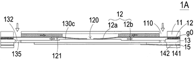
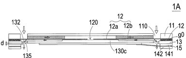
도 1A 및 도 2A에 도시된 바와 같이, 소형 공압 장치(1)는 소형 유체 제어 장치(1A) 및 소형 밸브 장치(1B)를 포함한다. 이 실시예에서, 소형 유체 제어 장치(1A)는 하우징(1a), 압전 액추에이터(13), 제 1 절연 플레이트(141), 전도성 플레이트(15) 및 제 2 절연 플레이트를 포함한다. 상기 하우징(1a)은 가스 포집 플레이트(16) 및 베이스(10)를 포함한다. 상기 베이스(10)는 가스 유입 플레이트(11), 공진 플레이트(12)를 포함한다. 압전 액추에이터(13)는 공진 플레이트(12)와 정렬된다. 가스 유입 플레이트(11), 공진 플레이트(12), 압전 장공기(13), 제 1 절연 플레이트(141), 전도성 플레이트(15), 제 2 절연 플레이트(142) 및 가스 포집 플레이트(16)는 순차적으로 서로 적층된다. 또한, 압전 액추에이터(13)는 서스펜션 플레이트(130), 외부 프레임(131), 적어도 하나의 브래킷(132) 및 압전 세라믹 플레이트(133)을 포함한다. 상기 실시예에서, 소형 밸브 장치(1B)는 밸브 플레이트(17) 및 가스 유출 플레이트(18)를 포함한다.1A and 2A, the small
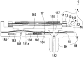
도 1A에 도시된 바와 같이, 가스 포집 플레이트(16)은 바닥 플레이트와 측벽(168)을 포함한다. 측벽(168)은 바닥 플레이트의 에지로부터 돌출된다. 가스 포집 플레이트(16)의 길이는 9mm와 17mm 사이의 범위이다. 가스 포집 플레이트(16)의 폭은 9mm와 17mm 사이의 범위이다. 바람직하게는, 가스 포집 플레이트(16)의 길이/폭 비율은 0.53 내지 1.88의 범위 내이다. 또한, 수용 공간(16a)은 바닥 플레이트과 측벽(168)에 의해 형성된다. 압전 액추에이터(13)는 수용 공간(16a) 내에 배치된다. 소형 공압 장치(1)가 조립된 후, 정면으로 본 소형 공압 장치의 최종 구조가 도 1B 및 도 7A 내지 도 7E에 도시된다. 소형 유체 제어 장치(1A)와 소형 밸브 장치(1B)는 함께 결합된다. 즉, 소형 밸브 장치(1B)의 밸브 플레이트(17)와 가스 유출 플레이트(18)는 서로 적층되어 소형 유체 제어 장치(1A)의 가스 포집 플레이트(16) 상에 위치된다. 가스 출구 플레이트(18)는 압력 해제 천공(181) 및 유출 구조(19)를 포함한다. 유출 구조(19)는 장비(미도시)와 연결되어 있다. 소형 밸브 장치(1B) 내의 기체가 압력 해제 천공(181)으로부터 해제되면, 압력 해제 목적이 달성된다.1A, the
소형 유체 제어 장치(1A)와 소형 밸브 장치(1B)가 결합된 후, 소형 공압 장치(1)가 조립된다. 결과적으로, 가스 유입 플레이트(11)의 적어도 하나의 입구(110)를 통해 소형 유체 제어 장치(1A) 내로 가스가 공급된다. 압전 액추에이터(13)의 작용에 응답하여, 가스는 복수의 압력 챔버(미도시)르 통하여 하향으로 전달된다. 그 후, 가스는 소형 밸브 장치(1B)를 통해 한 방향으로 전달된다. 가스의 압력은 소형 밸브 장치(1B)의 유출 구조(19)와 연통하는 장비(미도시)에 축적된다. 압력을 해제하기 위해, 소형 유체 제어 장치(1A)의 출력 가스량은 소형 밸브 장치(1B)의 가스 유출 플레이트(18)의 압력 해제 천공(181)으로부터 유출된다.After the small
도 1A 및 도 2A를 다시 참조하면, 소형 유체 제어 장치(1A)의 가스 유입 플레이트(11)은 제 1 표면(11b), 제 2 표면(11a) 및 적어도 하나의 입구(110)를 포함한다. 상기 실시 예에서, 가스 유입 플레이트(11)는 4개의 입구(110)를 포함한다. 상기 입구(110)는 가스 유입 플레이트(11)의 제 1 표면(11b) 및 제 2 표면(11a) 사이에 제공된다. 대기압의 작용에 응답하여, 가스는 적어도 하나의 입구(110)를 통해 소형 유체 제어 장치(1A) 내로 도입될 수 있다. 도 2A에 도시된 바와 같이, 적어도 하나의 수렴 채널(112)은 가스 유입 플레이트(11)의 제 1 표면(11b)에 형성된다. 하나 이상의 수렴 채널(112)은 가스 유입 플레이트(11)의 제 2 표면(11a)에서 적어도 하나의 입구(110)와 연통한다. 적어도 하나의 수렴 채널(112)의 수는 적어도 하나의 입구(110)의 수와 동일하다. 상기 실시 예에서, 가스 유입 플레이트(11)는 4개의 수렴 채널(112)을 포함한다. 하나 이상의 수렴 채널 채널(112)의 수 및 적어도 하나의 입구(110)의 수는 실제 요구 조건에 따라 변경될 수 있다. 또한, 중앙 공동(111)은 가스 유입 플레이트(11)의 제 1 표면(11b)에 형성되고 4개의 수렴 채널(112)의 중앙 수렴 영역에 위치한다. 중앙 공동(111)은 적어도 하나의 수렴 채널(112)과 연통한다. 가스는 적어도 하나의 입구(110)를 통해 적어도 하나의 수렴 채널(112)로 도입되고, 가스는 중앙 공동(111)으로 안내된다. 상기 실시예에서, 적어도 하나의 입구(110), 적어도 하나의 수렴 채널(112) 및 가스 유입 플레이트(11)의 중앙 공동(111)은 일체로 형성된다. 중앙 공동(111)은 가스를 일시적으로 저장하기 위한 수렴 챔버이다.1A and 2A, the
가스 유입 플레이트(11)은 바람직하게는 스테인리스 강으로 제조되지만, 이에 제한되지는 않는다. 가스 유입 플레이트(11)의 두께는 0.4mm와 0.6mm 사이의 범위이고, 바람직하게는 0.5mm이다. 또한, 중앙 공동(111)에 의해 한정된 수렴 챔버의 깊이와 하나 이상의 수렴 채널(112)의 깊이는 동일하다. 예를 들어, 수렴 챔버의 깊이와 적어도 하나의 수렴 채널(112)의 깊이는 0.2mm와 0.3mm 사이의 범위 내에 있다. 바람직하게는, 배타적이지는 않지만, 공진 플레이트(12)은 가요성 재료로 제조된다. 공진 플레이트(12)는 가스 유입 플레이트(11)의 중앙 공동(111)에 대응하는 중앙 구멍(120)을 포함한다. 결과적으로, 가스는 중앙 구멍(120)을 통해 하향 전달될 수 있다. 공진 플레이트(12)의 두께는 0.03mm 내지 0.08mm, 바람직하게는 0.05mm이다.The
도 3A는 도 1A의 소형 공압 장치의 압전 액추에이터를 정면에서 본 사시도이다. 무화과. 도 3B는 도 1A의 소형 공압 장치의 압전 액추에이터를 후방에서 본 개략적 사시도이다. 도 3C는 도 1A의 소형 공압 장치의 압전 액추에이터를 도시한 개략적 인 단면도이다. 도 3A, 도 3B 및 도 3C에 도시된 바와 같이, 압전 액추에이터(13)는 서스펜션 플레이트(130), 외부 프레임(131), 적어도 하나의 브래킷(132) 및 압전 세라믹 플레이트(133)를 포함한다. 압전 세라믹 플레이트(133)는 서스펜션 플레이트(130)의 제 1 표면(130b)에부착된다. 압전 세라믹 플레이트(133)는 인가된 전압에 따라 곡률 진동을 받는다. 서스펜션 플레이트(130)는 중간부(130d)와 주변부(130e)를 포함한다. 압전 세라믹 플레이트(133)가 곡률 진동을 받을 때, 서스펜션 플레이트(130)는 중간부(130d)로부터 주변부(130e)로 곡률 진동을 받는다. 적어도 하나의 브라켓(132)은 서스펜션 플레이트(130)와 외부 프레임(131) 사이에 배치된다. 즉, 적어도 하나의 브래킷(132)은 서스펜션 플레이트(130)와 외부 프레임(131) 사이에 연결된다. 브래킷(132)의 두 단부는 외부 프레임(131)과 서스펜션 플레이트(130)와 각각 연결된다. 결과적으로 브래킷(131)은 서스펜션 플레이트(130)를 탄성적으로 지지한다. 또한, 브래킷(132), 서스펜션 플레이트(130) 및 외부 프레임(131) 사이에는 가스가 통과할 수 있도록 적어도 하나의 빈 공간(135)이 형성된다. 상기 서스펜션 플레이트(130) 및 상기 외부 프레임(131)의 종류 및 적어도 하나의 브래킷(132)의 종류 및개수는 실제 요구 사항에 따라 달라질 수 있다. 또한, 도전성 핀(134)이 상기 외부 프레임(131)의 외측으로 돌출되어 외부 회로(미도시)와 전기적으로 연결된다.3A is a front view of the piezoelectric actuator of the miniature pneumatic device of FIG. 1A. FIG. Fig. 3B is a schematic perspective view of the piezoelectric actuator of the miniature pneumatic device of Fig. 1A viewed from the rear. Fig. FIG. 3C is a schematic cross-sectional view showing the piezoelectric actuator of the miniature pneumatic device of FIG. 1A. The
본 실시예에서, 서스펜션 플레이트(130)는 계단형 구조이다. 즉, 상기 서스펜션 플레이트(130)는 돌출부(130c)를 포함한다. 돌출부(130c)는 서스펜션 플레이트(130)의 제 2 표면(130a)에 형성된다. 예를 들어, 돌출부(130c)는 원형 볼록 구조이다. 돌출부(130c)의 두께는 0.02mm 내지 0.08mm의 범위, 바람직하게는 0.03mm이다. 바람직하게, 비제한적으로 돌출부(130c)의 직경은 서스펜션 플레이트(130)의 짧은 변 길이의 0.55 배이다. 도 3A 및 도 3C에 도시된 바와 같이, 서스펜션 플레이트(130)의 돌출부(130c)의 상부 표면은 외부 프레임(131)의 제 2 표면(131a)과 동일 평면상에 있고, 서스펜션 플레이트(130)의 제 2 표면(130a)은 브래킷(132)의 제 2 표면(132a)과 동일 평면상에 있다. 또한 서스펜션 플레이트(130)의 돌출부(130c)(또는 외부 프레임(131)의 제 2 표면(131a))는 서스펜션 플레이트(130)의 제 2 표면(130a)(또는 브래킷(132)의 제 2 표면(132a))에 대해 일정한 두께를 가진다. 도 3B 및 도 3C에 도시된 바와 같이, 상기 서스펜션 플레이트(130)의 제 1 표면(130b), 상기 외부 프레임(131)의 제 1 표면(131b) 및 상기 브래킷(132)의 제 1 표면(132b)은 서로 동일 평면상에 있다. 압전 세라믹 플레이트(133)는 서스펜션 플레이트(130)의 제 1 표면(130b)에부착된다. 다른 실시예에서, 서스펜션 플레이트(130)는 두개의 평평한 표면을 갖는 정방 플레이트 구조이다. 즉, 상기 서스펜션 플레이트(130)의 구조는 실제 요구 조건에 따라 달라질 수 있다. 본 실시예에서, 서스펜션 플레이트(130), 적어도 브래킷(132) 및 외부 프레임(131)은 금속 플레이트(예를 들어, 스테인레스 스틸 플레이트)를 사용하여 일체로 형성 및 제조된다. 상기 서스펜션 플레이트(130)의 두께는 0.1mm 내지 0.4mm이며, 바람직하게는 0.27mm이다. 서스펜션 플레이트(130)의 길이는 7.5mm와 12mm 사이의 범위이고, 바람직하게는 7.5mm와 8.5mm 사이의 범위이다. 서스펜션 플레이트(130)의 폭은 7.5mm와 12mm 사이의 범위이고, 바람직하게는 7.5mm와 8.5mm 사이의 범위이다. 외부 프레임(131)의 두께는 0.2mm와 0.4mm 사이의 범위이고, 바람직하게는 0.3mm이다.In this embodiment, the
압전 세라믹 플레이트(133)의 두께는 0.05 ㎜ 내지 0.3 ㎜, 바람직하게는 0.10 ㎜의 범위이다. 압전 세라믹 플레이트(133)의 길이는 서스펜션 플레이트(130)의 길이보다 크지 않다. 압전 세라믹 플레이트(133)의 길이는 7.5mm와 12mm 사이의 범위이고, 바람직하게는 7.5mm와 8.5mm 사이의 범위이다. 압전 세라믹 플레이트(133)의 폭은 7.5mm 내지 12mm의 범위이고, 바람직하게는 7.5mm 내지 8.5mm의 범위이다. 또한, 압전 세라믹 플레이트(133)의 길이/폭 비율은 0.625와 1.6 사이의 범위이다. 일부 실시예에서, 압전 세라믹 플레이트(133)의 길이는 서스펜션 플레이트(130)의 길이보다 작다. 유사하게 압전 세라믹 플레이트(133)는 서스펜션 플레이트(130)에 해당하는 정방형 플레이트이다.The thickness of the piezoelectric
본 발명의 소형 공압 장치(1)에 사용되는 압전 액추에이터(13)의 서스펜션 플레이트(130)는 정방 서스펜션 플레이트인 것이 바람직하다. 원형 서스펜션 플레이트(예를 들어, 도 4A에 도시된 바와 같은 원형 서스펜션 플레이트(j0))와 비교하여, 정방형 서스펜션 플레이트는 더 절전적이다. 다양한 유형 및 크기의 서스펜션 플레이트에 대한 소비 전력과 작동 주파수의 비교는 표 1에 도시된다.The
표 1의 결과로부터, 정방 서스펜션 플레이트(8mm~10mm)를 갖는 압전 액추에이터는 원형 서스펜션 플레이트(8mm~10mm)를 갖는 압전 액추에이터 보다 절전 효과가 높다는 것을 알 수 있다. 즉, 정방 서스펜션 플레이트를 갖는 압전 액추에이터는 소비 전력이 적다. 일반적으로, 공진 주파수에서 용량성부하의 소비 전력은 공진 주파수와 양의 상관 관계가 있다. 정방 서스펜션 플레이트의 공진 주파수가 원형 정방 서스펜션 플레이트의 공진 주파수보다 명백하게 낮기 때문에, 정방 서스펜션 플레이트의 소비 전력은 더 낮다. 정방 서스펜션 플레이트는 원형 서스펜션 플레이트보다 더 절전적이기 때문에 정방 서스펜션 플레이트가 착용 장치에 사용되기에 적합하다. 정방 서스펜션 플레이트가 원형 서스펜션 플레이트보다 절전 효과가 있다는 사실은 이론적인 수학 공식보다는 실험 결과에 따라 달성된다.From the results shown in Table 1, it can be seen that the piezoelectric actuator having the square suspension plate (8 mm to 10 mm) has a higher power saving effect than the piezoelectric actuator having the circular suspension plate (8 mm to 10 mm). That is, the piezoelectric actuator having the tetragonal suspension plate has low power consumption. Generally, the power consumption of the capacitive load at the resonant frequency is positively correlated with the resonant frequency. Since the resonant frequency of the tetragonal suspension plate is clearly lower than the resonant frequency of the circular tetragonal suspension plate, the power consumption of the tetragonal suspension plate is lower. Because the square suspension plate is more power-saving than the circular suspension plate, the square suspension plate is suitable for use in a wearing apparatus. The fact that the square suspension plate has a lower power saving than the circular suspension plate is achieved according to the experimental results rather than the theoretical mathematical formulas.
도 4A, 4B 및 4C는 본 발명의 소형 공압 장치에 사용되는 다양한 예시적인 압전 액추에이터를 개략적으로 도시한다. 도면에 도시된 바와 같이, 압전 액추에이터(13)의 서스펜션 플레이트(130), 외부 프레임(131) 및 적어도 하나의 브래킷(132)은 다양한 형태를 갖는다.Figures 4A, 4B and 4C schematically illustrate various exemplary piezoelectric actuators used in the miniature pneumatic device of the present invention. As shown in the figure, the
도 4A는 압전 액추에이터의 유형(a)~(l)을 개략적으로 도시한다. 유형(a)에 있어서, 외부 프레임(a1)과 서스펜션 플레이트(a0)는 정방형이며, 외부 프레임(a1)과 서스펜션 플레이트(a0)는 8개의 브래킷(a2)을 통해 서로 연결되고, 빈공간(a3)은 가스를 통과시키기 위해 브래킷(a2), 서스펜션 플레이트(a0) 및 외부 프레임(a1) 사이에 형성된다. 유형(i)에서, 외부 프레임(i1)과 서스펜션 플레이트(i0)도 정방형이지만, 외부 프레임(i1)과 서스펜션 플레이트(i0)는 2개의 브래킷(i2)을 통해 연결된다. 또한, 각 유형(b)~(h)의 외부 프레임 및 서스펜션 플레이트 또한 정방형이다. 각 유형(j)~(l)에서, 서스펜션 플레이트는 원형이고, 외부 프레임은 아크형 모서리를 갖는 정방형을 가진다. 예를 들어, 유형(j)에서, 서스펜션 플레이트(j0)는 원형이고, 외부 프레임은 아크형 모서리를 갖는 정방형을 가진다.Fig. 4A schematically shows types (a) to (l) of piezoelectric actuators. In the type (a), the outer frame a1 and the suspension plate a0 are square, the outer frame a1 and the suspension plate a0 are connected to each other through eight brackets a2, Is formed between the bracket a2, the suspension plate a0, and the outer frame al to allow gas to pass therethrough. In the type (i), the outer frame i1 and the suspension plate i0 are also square, but the outer frame i1 and the suspension plate i0 are connected via two brackets i2. In addition, the outer frame and the suspension plate of each type (b) to (h) are also square. In each type (j) to (l), the suspension plate is circular, and the outer frame has a square with arc-shaped corners. For example, in type j, the suspension plate j0 is circular and the outer frame has a square with arc-shaped edges.
도 4B는 압전 액추에이터의 유형(m)~(r)을 개략적으로 도시한다. 이러한 유형(m)~(r)에서, 서스펜션 플레이트(130) 및 외부 프레임(131)은 정방형이다. 유형(m)에서, 외부 프레임(m1)과 서스펜션 플레이트(m0)는 정방형이고, 외부 프레임(m1)과 서스펜션 플레이트(m0)는 4개의 브래킷(m2)으로 서로 연결되며, 가스가 통과하도록 브래킷(m2), 서스펜션 플레이트(m0) 및 외부 프레임(m1)사이에 빈 공간(m3)이 형성된다. 외부 프레임(m1)과 서스펜션 플레이트(m0) 사이의 브래킷(m2)은 연결부이다. 브래킷(m2)은 두 단부(m2'및 m2")를 가진다. 브래킷(m2)의 단부(m2')는 외부 프레임(m1)과 연결된다. 브래킷(m2)의 단부(m2")는 서스펜션 플레이트(m0)와 연결된다. 2개의 단부(m2', m2")는 서로 대향하고 동일한 수평선을 따라 배열된다. 유형(n)에서, 외부 프레임(n1)과 서스펜션 플레이트(m0)는 정방형이고, 외부 프레임(n1)과 서스펜션 플레이트(n0)는 4개의 브래킷(n2)을 통해 서로 연결되며, 가스가 통과하도록 브래킷(n2), 서스펜션 플레이트(n0) 및 외부 프레임(n1) 사이에는 빈공간이 형성된다. 외부 프레임(n1)과 서스펜션 플레이트(n0) 사이의 브래킷(n2)은 연결부이다. 브래킷(n2)은 두 개의 단부(n2' 및 n2")를 갖는다. 브래킷(n2)의 단부(n2')는 외부 프레임(n1)과 연결된다. 브라켓(n2)의 단부(n2")는 서스펜션 플레이트(n0)와 연결된다. 2개의 단부(n2', n2")는 동일한 수평선을 따라 배열되지 않는다. 예를 들어, 두 단부(n2', n2")는 수평선에 대해 0~45도 기울어 져 있고, 두 단부(n2', n2")는 인터레이스되어 있다. 유형(o)에서, 외부 프레임(o1)과 서스펜션 플레이트(o0)가 정방형이고, 외부 프레임(o1)과 서스펜션 플레이트(o0)가 4개의 브래킷(o2)으로 서로 연결되어 있으며, 가스가 통과하도록 빈공간이 브래킷(o2), 서스펜션 플레이트(o0) 및 외부 프레임(o1) 사이에 형성된다. 외부 프레임(o1)과 서스펜션 플레이트(o0) 사이의 브래킷(o2)은 연결부이다. 브래킷(o2)은 두 단부(o2' 및 o2")를 가진다. 브래킷(o2)의 단부(o2')는 외부 프레임(o1)과 연결된다. 브래킷(o2)의 단부(o2")는 서스펜션 플레이트(o0)에 연결된다. 2개의 단부(o2', o2")는 서로 대향하고 동일한 수평선을 따라 배열된다. 상기 유형과 비교하여, 브래킷(o2)의 프로파일이 구별된다.Fig. 4B schematically shows the types (m) to (r) of the piezoelectric actuator. In this type (m) to (r), the
타입(p)에서, 외부 프레임(p1)과 서스펜션 플레이트(p0)이 정방형이고, 외부 프레임(p1)과 서스펜션 플레이트(p0)이 4 개의 브래킷(p2)을 통해 서로 연결되어 있고, 공기가 통과하도록 빈 공간(p3)이 브래킷(p2), 서스펜션 플레이트(p0) 및 외부 프레임(p1) 사이에 형성된다. 외부 프레임(p1)과 서스펜션 플레이트(p0) 사이의 브래킷(p2)은 제 1 연결부(p20), 중간부(p21) 및 제 2 연결부(p22)를 포함한다. 중간부(p21)는 빈 공간(p3)에 형성되고 외부 프레임(p1) 및 서스펜션 플레이트(p0)과 평행하게 형성된다. 제 1 연결부(p20)는 중간부(p21)와 서스펜션 플레이트(p0) 사이에 배치된다. 제 2 연결부(p22)는 중간부(p21)와 외부 프레임(p1) 사이에 배치된다. 제 1 연결부(p20)와 제 2 연결부(p22)는 서로 마주하여 동일한 수평선을 따라 배치된다.In the type p, the outer frame p1 and the suspension plate p0 are square, the outer frame p1 and the suspension plate p0 are connected to each other through the four brackets p2, An empty space p3 is formed between the bracket p2, the suspension plate p0 and the outer frame p1. The bracket p2 between the outer frame p1 and the suspension plate p0 includes a first connecting portion p20, an intermediate portion p21 and a second connecting portion p22. The intermediate portion p21 is formed in the empty space p3 and is formed in parallel with the outer frame p1 and the suspension plate p0. The first connecting portion p20 is disposed between the intermediate portion p21 and the suspension plate p0. The second connecting portion p22 is disposed between the intermediate portion p21 and the outer frame p1. The first connection portion p20 and the second connection portion p22 are disposed to face each other along the same horizontal line.
타입(q)에서, 외부 프레임(q1), 서스펜션 플레이트(q0), 브래킷(q2) 및 빈 공간(q3)은 유형(m) 및 유형(o)과 유사하다. 그러나, 브래킷 q2의 구조는 구별된다. 서스펜션 플레이트 q0는 정방형이다. 서스펜션 플레이트(q0)의 각 변은 2 개의 연결부(q2)를 통해 외부 프레임(q1)의 대응 변과 연결된다. 각 연결부(q2)의 두 단부(q2', q2")는 서로 대향하고 동일한 수평선을 따라 배열된다. 유형(r)에서, 외부 프레임(r1), 서스펜션 플레이트(r0), 브래킷(r2) 및 빈 공간(r3)은 상기 실시 형태와 마찬가지이다. 그러나, 브래킷(r2)은 V 형 연결부이다. 즉, 브래킷(r2)은 외부 프레임(r1)과 서스펜션 플레이트(r0)에 0° 내지 45°의 경사각으로 연결된다. 브래킷(r2)의 단부(r2")는 서스펜션 플레이트(r0)에 연결되고, 브래킷(r2)의 두 단부(r2')는 외부 프레임(r1)에 연결된다. 즉, 단부(b2' 및 b2")들은 동일한 수평선을 따라 배치되지 않는다.In the type q, the outer frame q1, the suspension plate q0, the bracket q2 and the empty space q3 are similar to the type m and the type o. However, the structure of the bracket q2 is distinguished. The suspension plate q0 is square. Each side of the suspension plate q0 is connected to a corresponding side of the outer frame q1 through two connecting portions q2. In the type r, the outer frame r1, the suspension plate r0, the bracket r2, and the bellows r2 are arranged in parallel with each other, That is, the bracket r2 is fixed to the outer frame r1 and the suspension plate r0 at an angle of inclination of 0 ° to 45 ° with respect to the outer frame r1 and the suspension plate r0, The end portion r2 "of the bracket r2 is connected to the suspension plate r0 and the two ends r2 'of the bracket r2 are connected to the outer frame r1. That is, the ends b2 'and b2' 'are not disposed along the same horizontal line.
도 4C는 압전 액추에이터의 유형(s)~(x)을 개략적으로 도시한다. 유형(s)~(x)의 구조는 유형(m)~(r) 각각의 구조와 유사하다. 그러나, 유형(s)~(x)에서, 압전 액추에이터(13)의 서스펜션 플레이트(130)는 돌출부(130c)를 갖는다. 유형(s)~(x)의 돌출부(130c)는 각각 s4, t4, u4, v4, w4 및 x4로 표시된다. 상기 서스펜션 플레이트(130)는 정방형이기 때문에 절전 효과가 있다. 상술한 바와 같이, 본 발명의 서스펜션 플레이트로서, 2 개의 평탄한면을 갖는 사각 플레이트 구조 및 돌출부를 포함하는 계단형 구조가 적합하게 사용된다. 또한, 외부 프레임(131)과 서스펜션 플레이트(130) 사이의 브라켓(132)의 수는 실제 요구 사항에 따라 달라질 수 있다. 또한, 서스펜션 플레이트(130), 외곽 프레임(131) 및 브래킷(132)은 일체로 형성되어 있으며, 종래의 기계 가공 공정, 포토리소그래피 및 에칭 공정, 레이저 가공 공정, 전기 주조 공정, 방전 가공 가공 공정 등에 의해 제공된다.Fig. 4C schematically shows types (s) to (x) of the piezoelectric actuator. The structures of types (s) to (x) are similar to the structures of each of types (m) to (r). However, in types (s) to (x), the
다시 도 1A 및 도 2A를 참조하면, 소형 유체 제어 장치(1A)는 제 1 절연 플레이트(141), 전도성 플레이트(15) 및 제 2 절연 플레이트(142)을 더 포함한다. 제 1 절연 플레이트(141), 전도성 플레이트(15) 및 제 2 절연 플레이트(142)는 서로 연속적으로 적층되고 압전 액추에이터(13)아래에 위치된다. 제 1 절연 플레이트(141), 전도성 플레이트(15) 및 제 2 절연 플레이트(142)의 형상은 압전 액추에이터(13)의 외부 프레임(131)의 프로파일과 일치한다. 제 1 절연 플레이트(141)과 제 2 절연 플레이트(142)는 절연 효능을 제공하기 위한 절연 재료(예: 플라스틱 재료)로 만들어진다. 전도성 플레이트(15)는 전기 전도성을 제공하기 위해 전기 전도성 물질(예를 들어, 금속 물질)로 만들어진다. 또한, 전도성 플레이트(15)는 외부 회로(미도시)와 전기적으로 접속되도록 전도성 핀(151)을 갖는다.1A and 2A, the small
도 5A 내지 도 5E는 도 1A의 소형 공압 장치의 소형 유체 제어 장치의 작용을 개략적으로 도시한다. 도 5A에 도시된 바와 같이, 소형 유체 제어 장치(1A)의 가스 유입 플레이트(11), 공진 플레이트(12), 압전 액추에이터(13), 제 1 절연 플레이트(141), 전도성 플레이트(15) 및 제 2 절연 플레이트(142)는 서로 순차적으로 적층된다. 또한, 공진 플레이트(12)와 압전 액추에이터(13)의 외부 프레임(131) 사이에는 갭(g0)이 있다. 본 실시예에서는 갭(g0)에 필러(예를 들어, 전도성 접착제)가 삽입되어 있다. 결과적으로, 공진 플레이트(12)와 서스펜션 플레이트(130)의 돌출부(130c) 사이의 갭(g0)의 깊이는 가스가 보다 신속하게 유동하게 안내되도록 유지될 수 있다. 또한, 공진 플레이트(12)와 서스펜션 플레이트(130)의 돌출부(130c) 사이의 적절한 거리로 인해 접촉 간섭이 감소되고 발생하는 잡음이 크게 감소된다.Figures 5A-5E schematically illustrate the operation of a small fluid control device of the miniature pneumatic device of Figure IA. 5A, the
도 5A 내지 도 5E를 다시 참조하면, 가스 유입 플레이트(11), 공진 플레이트(12) 및 압전 액추에이터(13)가 결합된 후, 공진 플레이트(12)의 중심 구멍(120)과 가스 유입 플레이트(11)가 협동하여 가스를 수렴시키는 수렴 챔버가 형성되고, 공진 플레이트(12)과 압전 액추에이터(13) 사이에는 가스를 일시적으로 저장하기 위한 챔버(121)가 형성된다. 제 1 챔버(121)는 공진 플레이트(12)의 중앙 구멍(120)을 통해 가스 유입 플레이트(11)의 제 1 표면(11b)에 형성된 중앙 공동(111)과 연통한다. 제 1 챔버(121)의 주변 영역은 압전 액추에이터(13)의 빈 공간(135)을 통해 하부의 소형 밸브 장치(1B)에 연통한다.5A to 5E, after the
소형 공압 장치(1)의 소형 유체 제어 장치(1A)가 작동될 때, 압전 액추에이터(13)는 인가된 전압에 의해 작동된다. 따라서, 압전 액추에이터(13)는 브래킷(132)을 지점으로하여 상하 방향을 따라 왕복 진동한다. 공진 플레이트(12)은 가볍고 얇다. 도 5B를 참조하면, 압전 액추에이터(13)가 인가된 전압에 따라 하방으로 진동될 때, 압전 액추에이터(13)의 공진 때문에 공진 플레이트(12)는 수직 방향을 따라 왕복 진동한다. 특히, 가스 유입 플레이트(11)의 중앙 공동(111)에 상응하는 공진 플레이트(12)의 부분은 만곡 변형된다. 이하, 가스 유입 플레이트(11)의 중앙 공동(111)에 대응하는 공진 플레이트(12)의 영역을 공진 플레이트(12)의 가동부(12a)라고 한다. 압전 액추에이터(13)가 하방으로 진동될 때, 공진 플레이트(12)의 가동부(12a)는 가스에 의해 압박되고, 압전 액추에이터(13)에 응답하여 진동하기 때문에, 곡률 변형을 겪게된다. 가스가 가스 입구 플레이트(11)의 적어도 하나의 입구(110)로 공급된 후, 가스는 적어도 하나의 수렴 채널(112)을 통해, 가스 입구 플레이트(11)의 중앙 공동(111)으로 전달된다. 그후 가스는 공진 플레이트(12)의 중앙 구멍(120)을 통해 전달되어 제 1 챔버(121)내로 하향 도입된다. 압전 액추에이터(13)가 작동됨에 따라, 공진 플레이트(12)의 공진이 발생한다. 결과적으로, 공진 플레이트(12)의 가동부(12)는 또한 수직 방향을 따라 왕복 진동한다.When the small
도 5C에 도시된 바와 같이, 공진 플레이트(12)는 압전 액추에이터(13)의 서스펜션 플레이트(130)의 돌출부(130c)와 하방으로 접촉하여 진동한다. 공진 플레이트(12)의 가동부(12a)를 제외한 영역은 고정부(12b)로 부른다. 한편, 상기 서스펜션 플레이트(130)와 공진 플레이트(12)의 고정부(12b) 사이의 갭은 줄어들지 않는다. 공진 플레이트(12)의 변형으로 인해 제 1 챔버(121)의 체적이 수축되고 제 1 챔버(121)의 중간 연통 공간이 폐쇄된다. 이 상태에서, 가스는 제 1 챔버(121)의 주변 영역을 향해 가압된다. 결과적으로, 가스는 압전 액추에이터(13)의 빈 공간(135)을 통해 하향 전달된다.As shown in Fig. 5C, the
도 5D에 도시된 바와 같이, 공진 플레이트(12)는 공진 플레이트(12)의 가동부(12a)가 만곡 변형된 후에 원위치로 복귀된다. 그후, 인가된 전압에 따라 압전 액추에이터(13)가 상방으로 진동한다. 결과적으로, 제 1 챔버(121)의 체적도 축소된다. 압전 액추에이터(13)가 진동 변위(d)에서 상승하기 때문에, 가스는 제 1 챔버(121)의 주변 영역을 향해 연속적으로 가압된다. 한편, 가스는 가스 입구 플레이트(11)의 적어도 하나의 입구(110)로 연속적으로 공급되어 중앙 공동(111)으로 전달된다.As shown in Fig. 5D, the
다음, 도 5E에 도시된 바와 같이, 압전 액추에이터(13)가 상향으로 진동하기 때문에 공진 플레이트(12)는 상방으로 이동한다. 즉, 공진 플레이트(12)의 가동부(12a)가 상방으로 이동한다. 이러한 상황에서, 중앙 공동(111) 내의 가스는 공진 플레이트(12)의 중심 개구(120)를 통해 제 1 챔버(121)로 전달된 후, 압전 액추에이터(13)의 빈 공간(135)을 통해 아래쪽으로 가스가 전달되고, 마지막으로 가스는 소형 유체 제어 장치(1A)로부터 유출된다.Next, as shown in Fig. 5E, since the
상기 설명으로부터, 공진 플레이트(12)가 왕복 운동으로 수직 방향을 따라 진동될 때, 공진 플레이트(12)과 압전 액추에이터(13) 사이의 갭(g0)은 공진 플레이트(12)의 진폭을 증가시키는데 도움이된다. 즉, 공진 플레이트(12)와 압전 액추에이터(13) 사이의 갭(g0)으로 인해, 공진이 발생할 때 공진 플레이트(12)의 진폭이 증가한다. 갭(g0)과 압전 액추에이터(13)의 진동 변위(d) 사이의 차이(x)는 공식 x = g0 - d로 주어진다. 다른 x 값에 대응하는 소형 공압 장치(1)의 최대 출력 압력에 대한 일련의 테스트가 수행된다. x≤0μm인 경우, 소형 공압 장치(1)는 소음을 발생시킨다. x = 1~5μm인 경우, 소형 공압 장치 1의 최대 출력 압력은 350mmHg이다. x = 5~10μm인 경우, 소형 공압 장치(1)의 최대 출력 압력은 250mmHg이다. x = 10~15μm인 경우, 소형 공압 장치(1)의 최대 출력 압력은 150mmHg이다. 차이 x와 최대 출력 압력 사이의 관계는 표 2에 나열되어 있다. 표 2의 값은 작동 주파수가 17kHz와 20kHz 사이의 범위에 있고 작동 전압이 10V와 20V 사이의 범위에 있을 때 얻어진다. 결과적으로, 소형 유체 제어 장치(1A)의 유체 채널에 압력 구배가 발생하여 가스가 고속으로 흐르게된다. 또한, 공급 방향과 유출 방향 사이에 임피던스 차가 있기 때문에, 가스는 입구 측으로부터 출구 측으로 전달될 수 있다. 또한, 출구 측이 가스 압력을 가지더라도, 소형 유체 제어 장치(1A)는 조용한 효율을 달성하면서 가스를 밀어낼 수 있는 능력을 여전히 가진다.The gap g0 between the
일부 실시예에서, 왕복 운동의 수직 방향을 따른 공진 플레이트(12)의 진동 주파수는 압전 액추에이터(13)의 진동 주파수와 동일하다. 즉, 공진 플레이트(12)와 압전 액추에이터(13)는 상향 또는 하방을 따라 동기하여 진동한다. 본 발명의 사상을 유지하면서 소형 유체 제어 장치(1A)의 작용에 대한 많은 변형 및 변경이 이루어질 수 있음을 알아야 한다.In some embodiments, the oscillation frequency of the
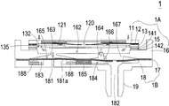
도 1A, 도 2A, 도 6A 및 도 6B를 참조하면, 도 6A는 도 1A의 소형 공압 장치의 가스 포집 플레이트 및 소형 밸브 장치의 가스 포집 작동을 개략적으로 도시한다. 도 6B는 도 1A의 소형 공압 장치의 가스 포집 플레이트 및 소형 밸브 장치의 가스 해제 작동을 개략적으로 도시한다. 도 1A 및 도 6A에 도시된 바와 같이, 소형 밸브 장치(1B)의 밸브 플레이트(17)와 가스 유출 플레이트(18)는 순차적으로 서로 적층된다. 또한, 소형 유체 제어 장치(1A)의 소형 밸브 장치(1B)와 가스 포집 플레이트(16)는 서로 협력한다.Referring to Figures 1A, 2A, 6A and 6B, Figure 6A schematically illustrates the gas collection operation of the gas collection plate and small valve device of the miniature pneumatic device of Figure 1A. Fig. 6B schematically shows the gas release operation of the gas collection plate and the small valve device of the miniature pneumatic device of Fig. 1A. As shown in Figs. 1A and 6A, the
가스 포집 플레이트(16)는 제 1 표면(160) 및 제 2 표면(161)(기점 표면으로도 지칭됨)을 포함한다. 가스 포집 플레이트(16)의 제 1 표면(160)은 가스 포집 챔버(162)를 형성하도록 오목하게 되어있다. 압전 액추에이터(13)는 가스 포집 챔버(162) 내에 수용된다. 소형 유체 제어 장치(1A)에 의해 하향으로 이동된 가스는 일시적으로 가스 포집 챔버(162)내에 축적된다. 가스 포집 플레이트(16)는 제 1 천공(163) 및 제 2 천공(164)을 포함한다. 제 1 천공(163)의 제 1 단부 및 제 2 천공(164)의 제 1 단부는 가스 포집 챔버(162)와 소통한다. 제 1 천공(163)의 제 2 단부 및 제 2 천공(164)의 제 2 단부는 가스 포집 챔버(162)의 제 2 표면(161)에 형성된 제 1 압력 해제 챔버(165) 및 제 1 유출 챔버(166)와 연통한다. 또한, 가스 포집 플레이트(16)는 제 1 유출 챔버(166)에 대응하는 융기 구조(167)를 갖는다. 예를 들어, 융기 구조(167)는 원통형 포스트를 포함하지만 이에 한정되지는 않는다. 융기 구조(167)의 두께는 가스 포집 플레이트(16)의 제 2 표면(161)보다 높은 레벨에 위치한다. 또한, 융기 구조(167)의 두께는 0.3mm 내지 0.55mm, 바람직하게는 0.4mm이다.The
가스 유출 플레이트(18)는 압력 해제 천공(181), 유출 천공(182), 제 1 표면(180)(기준 표면으로도 지칭됨) 및 제 2 표면(187)을 포함한다. 압력 해제 천공(181) 및 유출 천공(182)은 제 1 표면(180) 및 제 2 표면(187)을 관통한다. 가스 유출 플레이트(18)의 제 1 표면(180)은 오목하게 놓여 제 2 압력 해제 챔버(183) 및 제 2 유출 챔버(184)를 형성한다. 압력 해제 천공(181)은 제 2 압력 해제 챔버(183)의 중심에 위치된다. 또한, 가스 유출 플레이트(18)는 가스가 통과할 수 있도록 제 2 압력 해제 챔버(183)와 제 2 유출 챔버(184) 사이에 연통 채널(185)을 더 포함한다. 유출 천공(182)의 제 1 단부는 제 2 유출 챔버(184)와 연통한다. 유출 천공(182)의 제 2 단부는 유출 구조(19)와 연통된다. 유출 구조(19)는 장비(미도시)와 연결되어있다. 상기 장비는 예를 들어 가스 압력 구동 장비를 포함하나 이에 한정되지 않는다.The
밸브 플레이트(17)는 밸브 개구(170)와 복수의 위치 설정 개구(171)를 포함한다(도 1A 참조). 밸브 플레이트(17)의 두께는 0.1mm와 0.3mm 사이의 범위이고, 바람직하게는 0.2mm이다.The
가스 포집 플레이트(16), 밸브 플레이트(17) 및 가스 유출 플레이트(18)가 결합된 후, 가스 유출 플레이트(18)의 압력 해제 천공(181)은 가스 포집 플레이트(16)의 제 1 천공(163)과 정렬되고, 가스 유출 플레이트(18)의 제 2 압력 해제 챔버(183)는 가스 포집 플레이트(16)의 제 1 압력 해제 챔버(165)와 정렬되며, 가스 유출 플레이트(18)의 제 2 유출 챔버(184)는 가스 포집 플레이트(16)의 제 1 유출 챔버(166)와 정렬된다. 밸브 플레이트(17)는 가스 포집 플레이트(16)와 가스 유출 플레이트(18) 사이에 배치되어 제 1 압력 해제 챔버(165)와 제 2 압력 해제 챔버(183) 사이의 연통을 차단한다. 밸브 플레이트(17)의 밸브 개구(170)는 제 2 천공(164)과 유출 천공(182) 사이에 배치된다. 또한, 밸브 플레이트(17)의 밸브 개구(170)는 가스 포집 플레이트(16)의 제 1 유출 챔버(166)에 대응하는 돌출 구조물(167)과 정렬된다. 단일 밸브 개구(170)의 배열로 인해, 가스는 압력 차에 응답하여 소형 밸브 장치(1B)를 통해 한 방향으로 전달된다.After the
상기 실시 예에서, 가스 유출 플레이트(18)는 압력 해제 천공(181)의 제 1 단부 옆에 볼록한 구조(181a)를 갖는다. 바람직하게는, 볼록한 구조(181a)는 원통형 포스트이나 이에 제한되지는 않는다. 볼록 구조(181a)의 두께는 0.3mm 이상 0.55mm 이하, 바람직하게는 0.4mm 이하의 범위이다. 볼록 구조(181a)의 상부 표면은 가스 유출플레이트(18)의 제 1 표면(180)보다 높은 위치에 있다. 따라서, 압력 해제 천공(181)은 밸브플레이트(17)와 신속하게 접촉 및 폐쇄될 수 있다. 또한, 볼록 구조(181a)는 양호한 밀봉 효과를 달성하기 위한 예비 힘을 제공할 수 있다. 상기 실시 예에서, 가스 유출플레이트(18)는 위치 제한 구조(188)를 더 포함한다. 위치 제한 구조(188)의 두께는 0.32mm이다. 위치 제한 구조(188)는 제 2 압력 해제 챔버(183) 내에 배치된다. 바람직하게는 그러나 제한적이지는 않지만, 위치 제한 구조(188)는 링 형상 구조이다. 소형 밸브 장치(1B)의 가스 포집 작동이 수행되는 동안, 위치 제한 구조(188)는 밸브 플레이트(17)를 지지하는 것을 돕고 밸브 플레이트(17)의 붕괴를 피할 수 있다. 따라서, 밸브 플레이트(17)를 보다 신속하게 개폐할 수 있다.In this embodiment, the
이하, 도 6A를 참조하여 소형 밸브 장치(1B)의 가스 포집 동작을 설명한다. 소형 유체 제어 장치(1A)로부터의 가스가 소형 밸브 장치(1B)로 하향 전달되거나 대기압이 유출 구조(19)와 연통하는 장치의 내부 압력보다 높은 경우, 가스는 소형 유체 제어 장치(1A)로부터 가스 포집 플레이트(16)의 가스 포집 챔버(162)로 전달된다. 그 후, 가스는 제 1 천공(163) 및 제 2 천공(164)을 통해 제 1 압력 해제 챔버(165) 및 제 1 유출 챔버(166)로 하향 전달된다. 하향 가스에 응답하여, 가요성 밸브 플레이트(17)는 아래쪽으로 만곡 변형된다. 따라서, 제 1 압력 해제 챔버(165)의 체적이 팽창하고, 밸브 플레이트(17)는 제 1 관통 천공(163)에 대응하는 압력 해제 관통 천공(181)의 제 1 단부에 밀착된다. 이 상태에서, 가스 유출 플레이트(18)의 천공(181)이 폐쇄되어, 제 2 압력 해제 챔버(183) 내의 가스가 압력 해제 천공(181)으로부터 누설되지 않는다. 상기 실시예에서, 가스 유출 플레이트(18)는 압력 해제 천공(181)의 제 1 단부 옆에 볼록한 구조(181a)를 갖는다. 볼록한 구조(181a)의 배열로 인해, 압력 해제 천공(181)은 밸브 플레이트(17)에 의해 신속하게 폐쇄될 수 있다. 또한, 볼록 구조(181a)는 양호한 밀봉 효과를 달성하기 위한 예비 힘을 제공할 수 있다. 위치 제한 구조(188)는 밸브 플레이트(17)의 지지를 돕고 밸브 플레이트(17)의 붕괴를 피하기 위해 압력 해제 천공(181) 주위에 배열된다. 한편, 가스는 제 2 천공(164)을 통해 제 1 유출 챔버(166)로 하향 전달된다. 하향 가스에 반응하여, 제 1 유출 챔버(166)에 대응하는 밸브 플레이트(17)는 또한 하향 만곡 변형을 받는다. 결과적으로, 밸브 막(17)의 밸브 개구(170)는 그에 상응하여 하측으로 개방된다. 이 상황에서, 가스는 밸브 개구(170)를 통해 제 1 유출 챔버(166)로부터 제 2 유출 챔버(184)로 전달된다. 그 후, 가스는 유출 천공(182)을 통해 유출 구조(19)로 전달된 다음 유출 구조체(19)와 연통하는 장비로 전달된다. 결과적으로, 가스 압력을 포집하는 목적이 달성된다.Hereinafter, the gas collection operation of the
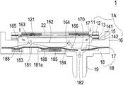
이하, 도 6B을 참조하여 소형 밸브 장치(1B)의 가스 배출 작동을 설명한다. 가스 해제 동작을 수행하기 위해, 사용자는 소형 유체 제어 장치(1A)에 공급되는 가스의 양을 조정하여 가스가 더 이상 가스 포집 챔버(162)로 이송되지 않도록 한다. 선택적을고, 유출 구조(19)와 연통하는 장비의 내부 압력이 대기압보다 높은 경우, 가스 배출 작동이 수행될 수 있다. 이 상태에서, 가스는 유출 구조(19)로부터 유출 천공(182)을 통해 제 2 유출 챔버(184)로 전달된다. 따라서, 제 2 유출 챔버(184)의 체적이 팽창되고, 제 2 유출 챔버에 대응하는 가요성 밸브 플레이트(17) 184)가 위쪽으로 만곡 변형된다. 또한, 밸브 플레이트(17)는 가스 포집 플레이트(16)와 밀착된다. 따라서, 밸브 플레이트(17)의 밸브 개구(170)는 가스 포집 플레이트(16)에 의해 폐쇄된다. 또한, 가스 포집 플레이트(16)는 제 1 유출 챔버(166)와 상응하는 융기 구조(167)를 가진다. 유기 구조(167)의 배열로 인해, 가요성 밸브 플레이트(17)는 보다 신속하게 상향 절곡될 수 있다. 또한, 융기 구조(167)는 밸브 개구(170)의 양호한 밀봉 효과를 달성하기 위한 예비 힘을 제공할 수 있다. 밸브 플레이트(17)의 밸브 개구(170)가 융기 구조(167)와 접촉하여 폐쇄되므로, 제 2 유출 챔버(184)의 가스는 제 1 유출 챔버(166)로 역으로 복귀되지 않는다. 결과적으로, 가스 누설을 피하는 효능이 향상된다. 또한, 제 2 유출 챔버(184)의 가스가 연통 채널(185)을 통해 제 2 압력 해제 챔버(183)로 전달되기 때문에, 제 2 압력 해제 챔버(183)의 체적이 확대된다. 결과적으로, 제 2 압력 해제 챔버(183)에 대응하는 밸브 플레이트(17)는 또한 상방 만곡 변형을 받는다. 밸브 플레이트(17)가 더 이상 압력 해제 천공(181)의 제 1 단부와 접촉하지 않기 때문에, 압력 해제 천공(181)이 개방된다. 이 상태에서, 제 2 압력 해제 챔버(183) 내의 가스는 압력 해제 천공(181)을 통해 출력된다. 결과적으로, 가스의 압력이 해제된다. 유사하게, 제 2 압력 해제 챔버(183) 내의 압력 해제 천공(181) 또는 위치 제한 구조(188) 옆의 볼록한 구조(181a)로 인해, 가요성 밸브 플레이트(17)는 보다 신속하게 상향 만곡 변형을 받을 수 있다. 결과적으로, 압력 해제 천공(181)은 신속하게 개방될 수 있다. 한 방향으로의 가스 해제 작동이 수행된 후, 유출 구조(19)와 연통하는 장비 내의 가스는 부분적으로 또는 전체적으로 주변으로 배출된다. 이 경우 장비의 압력이 감소한다.Hereinafter, the gas discharge operation of the
도 7A 내지 도 7E는 도 2A의 소형 공압 장치의 가스 포집 작용을 개략적으로 도시한다. 도 1A, 도 2A 및 도 7A 내지 도 7E를 참조한다. 도 7A에 도시된 바와 같이, 소형 공압 장치(1)는 소형 유체 제어 장치(1A) 및 소형 밸브 장치(1B)를 포함한다. 상술 한 바와 같이, 소형 유체 제어 장치(1A)의 가스 유입 플레이트(11), 공진 플레이트(12), 압전 액추에이터(13), 제 1 절연 플레이트(141), 전도성 플레이트(15), 제 2 절연 플레이트(142) 및 가스 포집 플레이트(16)는 순차적으로 적층되어있다. 또한, 공진 플레이트(12)와 압전 액추에이터(13) 사이에는 갭이 형성된다. 또한, 제 1 챔버(121)는 공진 플레이트(12)와 압전 액추에이터(13)사이에 형성된다. 소형 밸브 장치(1B)의 밸브 플레이트(17) 및 가스 유출 플레이트(18)는 서로 적층되어 소형 유체 제어 장치(1A)의 가스 포집 플레이트(16) 아래에 배치된다. 가스 포집 챔버(162)는 가스 포집 플레이트(16)와 압전 액추에이터(13)사이에 배치된다. 가스 포집 플레이트(16)의 제 2 표면(161)에는 제 1 압력 해제 챔버(165)와 제 1 유출 챔버(166)가 형성된다. 제 2 압력 해제 챔버(183) 및 제 2 유출 챔버(184)는 가스 유출 플레이트(18)의 제 1 표면(180)에 형성된다. 일 실시 예에서, 소형 공압 장치(1)의 동작 주파수는 27kHz와 29.5kHz 사이의 범위에 있고, 소형 공압 장치(1)의 작동 전압은 ±10V와 ±16V 사이의 범위 내에 있다. 또한, 복수의 압력 챔버의 배치, 압전 액추에이터(13)의 작동 및 플레이트(12)와 밸브 플레이트(17)의 진동으로 인해, 가스는 하향으로 전달될 수 있다.Figures 7A-7E schematically illustrate the gas collection action of the miniature pneumatic device of Figure 2A. See Figures 1A, 2A and 7A-7E. As shown in Fig. 7A, the small
도 7B에 도시된 바와 같이, 소형 유체 제어 장치(1A)의 압전 액추에이터(13)는 인가된 전압에 응답하여 하방으로 진동한다. 결과적으로, 가스는 가스 유입 플레이트(11)의 하나 이상의 입구(110)를 통해 소형 유체 제어 장치(1A)로 공급된다. 가스는 가스 유입 플레이트(11)의 적어도 하나의 수렴 채널(112)을 통해 중앙 공동(111)으로 순차적으로 수렴되고, 공진 플레이트(12)의 중앙 구멍(120)를 통해 전달되어 제 1 챔버(121)로 하향 도입된다.As shown in Fig. 7B, the
압전 액추에이터(13)가 작동됨에 따라, 공진 플레이트(12)의 공진이 발생한다. 결과적으로, 공진 플레이트(12)은 또한 왕복 운동으로 수직 방향을 따라 진동한다. 도 7C에 도시된 바와 같이, 공진 플레이트(12)는 압전 액추에이터(13)의 서스펜션 플레이트(130)의 돌출부(130c)와 하방으로 접촉하여 진동한다. 공진 플레이트(12)의 변형으로 인해 가스 유입 플레이트(11)의 중앙 공동(111)에 대응하는 챔버의 체적은 팽창되지만 제 1 챔버(121)의 체적은 수축된다. 이 상태에서, 가스는 제 1 챔버(121)의 주변 영역쪽으로 밀려 나게된다. 결과적으로, 가스는 압전 액추에이터(13)의 빈 공간(135)을 통해 아래쪽으로 이동한다. 그 후 가스는 소형 유체 제어 장치(1A)와 소형 밸브 장치(1B) 사이의 가스 포집 챔버(162)로 이송된다. 그 다음, 가스는 가스 포집 챔버(162)와 연통하는 제 1 천공(163) 및 제 2 천공(164)을 통해 제 1 압력 해제 챔버(165) 및 제 1 유출 챔버(166)로 하향 전달된다. 결과적으로, 공진 플레이트(12)가 왕복 운동으로 수직 방향을 따라 진동할 때, 공진 플레이트(12)와 압전 액추에이터(13) 사이의 갭(g0)은 공진 플레이트(12)의 진폭을 증가시키는데 도움이된다. 즉, 공진 플레이트(12)와 압전 액추에이터(13) 사이의 갭(g0)으로 인해, 공진이 발생할 때 공진 플레이트(12)의 진폭이 증가한다.As the
도 7d에 도시된 바와 같이, 소형 유체 제어 장치(1A)의 공진 플레이트(12)는 원래의 위치로 복귀되고, 압전 액추에이터(13)는 인가된 전압에 응답하여 상향으로 진동한다. 갭(g0)과 압전 액추에이터(13)의 진동 변위(d) 사이의 차이(x)는 공식: x = g0 - d로 주어진다. 다른 x 값에 대응하는 소형 공압 장치(1)의 최대 출력 압력에 대한 일련의 테스트가 수행된다. 소형 공압 장치(1)의 동작 주파수는 27kHz와 29.5kHz 사이이며, 소형 공압 장치(1)의 작동 전압은 ±10V와 ±16V 사이이다. x = 1 ~ 5μm인 경우, 소형 공압 장치(1)의 최대 출력 압력은 최소 300mmHg이다. 결과적으로, 제 1 챔버(121)의 체적도 축소되고, 가스는 제 1 챔버(121)의 주변 영역을 향해 연속적으로 가압된다. 또한, 가스는 압전 액추에이터(13)의 빈 공간(135)을 통해 가스 포집 챔버(162), 제 1 압력 해제 챔버(165) 및 제 1 유출 챔버(166)로 연속적으로 전달된다. 결과적으로, 제 1 압력 해제 챔버(165) 및 제 1 유출 챔버(166) 내의 압력은 점차적으로 증가하게된다. 증가된 가스 압력에 응답하여, 가요성 밸브 플레이트(17)는 하향 만곡 변형을 받는다. 따라서, 제 2 압력 해제 챔버(183)에 대응하는 밸브 플레이트(17)는 하방으로 이동하여 압력 해제 천공(181)의 제 1 단부에 대응하는 볼록 구조(181a)와 접촉된다. 이 상황에서, 가스 유출 플레이트(18)의 압력 해제 천공(181)은 폐쇄된다. 제 2 유출 챔버(184)에서, 유출 천공(182)에 대응하는 밸브 플레이트(17)의 밸브 개구(170)는 하향으로 개방된다. 그 다음, 제 2 유출 챔버(184) 내의 가스는 유출 천공(182)을 통해 유출 구조(19)로 하향 전달된 다음, 유출 구조(19)와 연통하는 장비로 전달된다. 결과적으로, 가스 압력 포집 목적이 달성된다.7D, the
그후, 도 7E에 도시된 바와 같이, 소형 유체 제어 장치(1A)의 공진 플레이트(12)가 상방으로 진동된다. 이러한 상황에서, 가스 유입 플레이트(11)의 중앙 공동(111) 내의 가스는 공진 플레이트(12)의 중앙 구멍(120)을 통해 제 1 챔버(121)로 전달된 후, 가스가 압전 액추에이터(13)의 빈 공간(135)을 통해 가스 포집 플레이트(16)로 하향 전달된다. 가스 압력이 하향 방향을 따라 연속적으로 증가함에 따라, 가스는 가스 포집 챔버(162), 제 2 천공(164), 제 1 유출 챔버(166), 제 2 유구 챔버(184) 및 유출 천공(182)으로 연속적으로 전달된 후, 유출 구조(19)와 연통하는 장비로 전달된다. 즉, 압력 포집 작동은 주변 압력과 장비의 내부 압력 사이의 압력 차에 의해 유발된다.Thereafter, as shown in Fig. 7E, the
도 8은 도 1A의 소형 공압 장치의 가스 해제 작용 또는 감압 작용을 개략적으로 도시한다. 유출 구조(19)와 연통하는 장비의 내부 압력이 대기압보다 높은 경우, 가스 해제 작동(또는 감압 작동)이 수행될 수 있다. 전술한 바와 같이, 사용자는 소형 유체 제어 장치(1A)에 공급되는 가스의 양을 조정하여 가스가 더 이상 가스 포집 챔버(162)로 전달되지 않도록 할 수 있다. 이러한 상황에서, 가스는 유출 구조(19)로부터 유출 천공(182)을 통해 제 2 유출 챔버(184)로 전달된다. 그 결과, 제 2 유출 챔버(184)의 체적이 팽창하고, 제 2 유출 챔버(184)에 대응하는 가요성 밸브 플레이트(17)가 상방으로 굽어진다. 또한, 밸브 플레이트(17)는 제 1 유출 챔버(166)에 대응하는 융기 구조(167)와 밀접하게 접촉한다. 밸브 플레이트(17)의 밸브 개구(170)가 융기 구조(167)에 의해 폐쇄되기 때문에, 제 2 유출 챔버(184) 내의 가스는 제 1 유출 챔버(166)로 역으로 복귀되지 않는다. 또한, 제 2 유출 챔버(184) 내의 가스는 연통 채널(185)을 통해 제 2 압력 해제 챔버(183)로 전달된 후, 제 2 압력 해제 챔버(183)의 가스가 압력 해제 천공(181)에 전달된다. 이러한 상황 하에서, 가스 해제 작동이 수행된다. 소형 밸브 장치(1B)의 한 방향 가스 해제 작동이 수행된 후, 유출 구조(19)와 연통하는 장비 내의 가스는 부분적으로 또는 전체적으로 주변으로 배출된다. 이 경우 장비의 내부 압력이 감소한다.Figure 8 schematically illustrates the degassing action or depressurizing action of the miniature pneumatic device of Figure IA. When the internal pressure of the equipment in communication with the
다른 크기의 정방형 서스펜션 플레이트를 가진 소형 공압 장치의 성능 데이터는 표 3에 나타난다.Performance data for small pneumatic devices with square suspension plates of different sizes are shown in Table 3.
플레이트의 측면길이Square Suspension
Side length of plate
상기 표의 결과는 크기가 다른 정방형의 서스펜션 플레이트가 있는 소형 공압 장치의 25개 샘플을 테스트하여 얻은 결과이다. 정방형 서스펜션 플레이트의 측면 길이는 7.5mm와 14mm 사이이다. 정방형 서스펜션 플레이트의 측면 길이가 감소함에 따라, 산출량과 최대 출력 압력이 모두 증가한다. 정방형 서스펜션 플레이트의 최적화된 측면 길이는 7.5mm와 8.5mm 사이이다. 최적화된 측면 길이에 해당하는 작동 주파수는 27kHz~29.5kHz 범위이며, 최대 출력 압력은 최소 300mmHg이다. 서스펜션 플레이트의 수직 진동에 대응하여 수평 방향의 변형량이 감소하는 것으로 추정된다. 즉, 수직 방향의 운동 에너지를 유효하게 이용할 수 있다. 또한, 서스펜션 플레이트의 측면 길이가 감소함에 따라, 수직 방향의 조립 오차도 감소된다. 결과적으로, 서스펜션 플레이트와 공진 플레이트 또는 다른 부품 사이의 충돌 간섭이 감소될 수 있고, 서스펜션 플레이트와 공진 플레이트 사이의 특정 거리가 유지될 수 있다. 이 상황에서 제품 수율이 향상되고 최대 출력 압력이 증가한다. 또한, 서스펜션 플레이트의 크기가 감소됨에 따라, 압전 액추에이터의 크기가 그에 따라 감소될 수 있다. 압전 액추에이터는 진동 중에 쉽게 기울어지지 않기 때문에, 가스 채널의 부피가 감소되고 가스를 밀거나 압축하는 효능이 증가된다. 결과적으로, 본 발명의 소형 공압 장치는 향상된 성능과 작은 크기를 갖는다. 압전 액추에이터의 서스펜션 플레이트 및 압전 세라믹 플레이트가 더 큰 경우, 서스펜션 플레이트의 강성이 저하되기 때문에 서스펜션 플레이트는 진동 중에 쉽게 변형된다. 서스펜션 플레이트의 왜곡이 발생하면 서스펜션 플레이트와 공진 플레이트 또는 다른 부품 사이의 충돌 간섭이 증가하여 소음이 발생한다. 소음 문제로 인해 제품에 결함이 발생할 수 있다. 즉, 서스펜션 플레이트의 크기와 압전 세라믹 플레이트의 크기가 커질수록 소형 공압 장치의 불량률이 증가하게된다. 서스펜션 플레이트의 크기와 압전 세라믹 플레이트의 크기를 줄임으로써 소형 공압 장치의 성능이 향상되고 소음이 감소하며 불량률이 감소한다. 서스펜션 플레이트의 크기 감소가 성능 및 최대 출력 압력을 증가시킨다는 사실은 이론적인 수학 공식보다는 실험 결과에 따라 달성된다.The results in the above table are the results of testing 25 samples of a miniature pneumatic device with a square suspension plate of different size. The lateral length of the square suspension plate is between 7.5 mm and 14 mm. As the lateral length of the square suspension plate decreases, both the throughput and the maximum output pressure increase. The optimized lateral length of the square suspension plate is between 7.5 mm and 8.5 mm. The operating frequency corresponding to the optimized side length ranges from 27kHz to 29.5kHz, with a maximum output pressure of at least 300mmHg. It is estimated that the deformation amount in the horizontal direction decreases corresponding to the vertical vibration of the suspension plate. That is, vertical kinetic energy can be effectively used. Further, as the side length of the suspension plate is reduced, the assembly error in the vertical direction is also reduced. As a result, collision interference between the suspension plate and the resonant plate or other part can be reduced, and a specific distance between the suspension plate and the resonant plate can be maintained. In this situation, product yield improves and maximum output pressure increases. Further, as the size of the suspension plate is reduced, the size of the piezoelectric actuator can be reduced accordingly. Since the piezoelectric actuator is not easily tilted during vibration, the volume of the gas channel is reduced and the efficiency of pushing or compressing the gas is increased. As a result, the compact pneumatic device of the present invention has improved performance and smaller size. When the suspension plate and the piezoelectric ceramic plate of the piezoelectric actuator are larger, the suspension plate is easily deformed during vibration because the rigidity of the suspension plate is lowered. When distortion of the suspension plate occurs, collision interference between the suspension plate and the resonant plate or other component increases, and noise is generated. Noise problems can cause defects in the product. That is, as the size of the suspension plate and the size of the piezoelectric ceramic plate become larger, the defective ratio of the small-sized pneumatic device increases. By reducing the size of the suspension plate and the size of the piezoelectric ceramic plate, the performance of the compact pneumatic device is improved, the noise is reduced, and the defect rate is reduced. The fact that the size reduction of the suspension plate increases performance and maximum output pressure is achieved according to the experimental results rather than the theoretical mathematical formulas.
소형 유체 제어 장치(1A)와 소형 밸브 장치(1B)가 결합된 후, 소형 공압 장치(1)의 전체 두께는 2㎜와 6㎜ 사이의 범위에 있다. 소형 공압 장치는 슬림하고 휴대용이기 때문에 의료 기기 또는 기타 적절한 장비에 적합하다.After the small
이상의 설명으로부터, 본 발명은 소형 유체 제어 장치를 위한 압전 액추에이터를 제공한다. 소형 유체 제어 장치 및 소형 밸브 장치는 소형 공압장치에 채용된다. 가스가 입구를 통해 소형 유체 제어 장치로 공급된 후, 압전 액추에이터가 작동된다. 결과적으로, 소형 유체 제어 장치 및 가스 포집 챔버의 유체 채널에 압력 구배가 발생되어 가스가 소형 밸브 장치로 고속으로 흐르게된다. 또한, 소형 밸브 장치의 한방향 밸브 플레이트로 인해, 가스는 한 방향으로 전달된다. 결과적으로 가스의 압력은 출구 구조와 연결된 모든 장비에 축적된다. 가스 배출 작동(또는 감압 작동)을 수행하기 위해, 사용자는 소형 유체 제어 장치로 공급될 가스의 양을 조절하여, 가스가 더 이상 가스 포집 챔버로 이송되지 않도록 할 수 있다. 이러한 상황하에서, 가스는 소형 밸브 장치의 유출 구조로부터 제 2 유출 챔버로 전달된 다음, 연통 채널을 통해 제 2 압력 해제 챔버로 전달되고, 마지막으로 압력 해제 천공으로부터 빠져나간다. 본 발명의 소형 공압 장치에 의하면, 가스를 신속하게 이송하면서 조용한 효과를 얻을 수 있다. 또한, 본 발명의 소형 공압 장치는 특별한 구성으로 인해 체적이 작고 두께가 얇다. 결과적으로, 소형 공압 장치는 휴대용이며 의료 장비 또는 기타 적절한 장비에 적용된다. 즉, 본 발명의 소형 공압 장치는 공업적 가치를 가진다.From the above description, the present invention provides a piezoelectric actuator for a compact fluid control device. Small fluid control devices and small valve devices are employed in small pneumatic devices. After the gas is supplied to the small fluid control device through the inlet, the piezoelectric actuator is actuated. As a result, a pressure gradient occurs in the fluid channels of the small fluid control device and the gas collection chamber, causing the gas to flow to the small valve device at high speed. Further, due to the one-way valve plate of the small valve device, the gas is transferred in one direction. As a result, the pressure of the gas accumulates in all equipment connected to the outlet structure. To perform the gas discharge operation (or decompression operation), the user can adjust the amount of gas to be fed to the small fluid control device, so that the gas is no longer transferred to the gas collection chamber. Under such circumstances, the gas is transferred from the outflow structure of the small valve device to the second outlet chamber, then through the communication channel to the second pressure release chamber, and finally out of the pressure release aperture. According to the small-sized pneumatic device of the present invention, a quiet effect can be obtained while rapidly transferring the gas. Further, the small-sized pneumatic device of the present invention has a small volume and a small thickness due to the special configuration. As a result, the compact pneumatic device is portable and applies to medical equipment or other appropriate equipment. That is, the compact pneumatic device of the present invention has industrial value.
본 발명은 현재 가장 실용적이고 바람직한 실시예로 고려되는 것에 관하여 설명되었지만, 본 발명은 개시된 실시예에 한정될 필요는 없다는 것을 이해하여야 한다. 반대로, 모든 수정 및 유사한 구조를 포함하도록 가장 넓은 해석과 일치하는 첨부된 청구 범위의 사상 및 범위 내에 포함되는 다양한 변형 및 유사한 배열을 포함하는 것으로 의도된다.While the invention has been described in connection with what is presently considered to be the most practical and preferred embodiment, it is to be understood that the invention is not limited to the disclosed embodiments. On the contrary, it is intended to cover various modifications and similar arrangements included within the spirit and scope of the appended claims, including the most broad interpretations so as to encompass all such modifications and similar structures.
Claims (10)
서스펜션 플레이트, 상기 서스펜션 플레이트는 정방형 구조이고, 상기 서스펜션 플레이트의 길이는 7.5mm 내지 12mm이고, 상기 서스펜션 플레이트는 중간부로부터 주변 부분으로 곡률 진동을 받도록 허용되고;
상기 서스펜션 플레이트 주위에 배치된 외부 프레임;
상기 서스펜션 플레이트를 탄성 지지하기 위해 상기 서스펜션 플레이트와 외부프레임 사이에 연결된 적어도 하나의 브래킷; 및
압전 세라믹 플레이트를 포함하여 구성되고,
상기 압전 세라믹 플레이트는 정방형이고, 압전 세라믹 플레이트의 길이는 서스펜션 플레이트의 길이보다 크지 않으며, 압전 세라믹 플레이트는 상기 서스펜션 플레이트의 제 1 표면에 부착되며,
전압이 상기 압전 세라믹 플레이트에 인가될때 상기 서스펜션 플레이트가 곡률 만곡되도록 구동되는 것을 특징으로 하는 압전 액추에이터.In the piezoelectric actuator,
The suspension plate is a square structure, the suspension plate has a length of 7.5 mm to 12 mm, and the suspension plate is allowed to receive a curvature vibration from an intermediate portion to a peripheral portion;
An outer frame disposed around the suspension plate;
At least one bracket coupled between the suspension plate and the outer frame for resiliently supporting the suspension plate; And
And a piezoelectric ceramic plate,
Wherein the piezoelectric ceramic plate is square, the length of the piezoelectric ceramic plate is not greater than the length of the suspension plate, the piezoelectric ceramic plate is attached to the first surface of the suspension plate,
And the suspension plate is driven so as to be curved when a voltage is applied to the piezoelectric ceramic plate.
상기 서스펜션 플레이트와 상기 외부 프레임 사이의 빈 공간에 형성되고 상기 외부 프레임 및 상기 서스펜션 플레이트와 평행한 중간부;
상기 중간부와 상기 서스펜션 프레임 사이에 배치된 제 1 연결부; 및
상기 중간부와 상기 외부 프레임 사이에 배치되며, 상기 제 1 연결부와 상기 제 2 연결부가 서로 마주하여 동일 수평선을 따라 배치되는 제 2 연결부를 포함하는 것을 특징으로 하는 압전 액추에이터.The apparatus of claim 1, wherein the at least one bracket comprises:
An intermediate portion formed in an empty space between the suspension plate and the outer frame and parallel to the outer frame and the suspension plate;
A first connection portion disposed between the intermediate portion and the suspension frame; And
And a second connection part disposed between the middle part and the outer frame, wherein the first connection part and the second connection part face each other and are arranged along the same horizontal line.
Applications Claiming Priority (14)
| Application Number | Priority Date | Filing Date | Title |
|---|---|---|---|
| TW105102842 | 2016-01-29 | ||
| TW105102843 | 2016-01-29 | ||
| TW105102843 | 2016-01-29 | ||
| TW105102842 | 2016-01-29 | ||
| TW105102845 | 2016-01-29 | ||
| TW105102845 | 2016-01-29 | ||
| TW105119823 | 2016-06-24 | ||
| TW105119824 | 2016-06-24 | ||
| TW105119825 | 2016-06-24 | ||
| TW105119824 | 2016-06-24 | ||
| TW105119825 | 2016-06-24 | ||
| TW105119823 | 2016-06-24 | ||
| TW105128580 | 2016-09-05 | ||
| TW105128580A TWI722012B (en) | 2016-01-29 | 2016-09-05 | Actuator |
Publications (1)
| Publication Number | Publication Date |
|---|---|
| KR20170091002A true KR20170091002A (en) | 2017-08-08 |
Family
ID=57681469
Family Applications (1)
| Application Number | Title | Priority Date | Filing Date |
|---|---|---|---|
| KR1020160183873A KR20170091002A (en) | 2016-01-29 | 2016-12-30 | Piezoelectric actuator |
Country Status (4)
| Country | Link |
|---|---|
| US (1) | US10388849B2 (en) |
| EP (1) | EP3203074B1 (en) |
| JP (1) | JP6585640B2 (en) |
| KR (1) | KR20170091002A (en) |
Families Citing this family (13)
| Publication number | Priority date | Publication date | Assignee | Title |
|---|---|---|---|---|
| US10438868B2 (en) * | 2017-02-20 | 2019-10-08 | Microjet Technology Co., Ltd. | Air-cooling heat dissipation device |
| TWI636188B (en) * | 2017-05-12 | 2018-09-21 | 研能科技股份有限公司 | Actuator |
| TWI684730B (en) * | 2017-08-08 | 2020-02-11 | 研能科技股份有限公司 | Driving and information-transmission system of air-filtering protector |
| TWI650154B (en) * | 2017-08-08 | 2019-02-11 | 研能科技股份有限公司 | Air-filtering protector |
| TWI636189B (en) * | 2017-08-21 | 2018-09-21 | 研能科技股份有限公司 | Micro-air control device |
| TWI689664B (en) * | 2017-08-25 | 2020-04-01 | 研能科技股份有限公司 | Air actuatung diversion device |
| TW201912248A (en) * | 2017-08-31 | 2019-04-01 | 研能科技股份有限公司 | Gas transmitting device |
| TWI663332B (en) * | 2017-08-31 | 2019-06-21 | 研能科技股份有限公司 | Gas transmitting device |
| TWI683059B (en) * | 2017-08-31 | 2020-01-21 | 研能科技股份有限公司 | Gas transmitting device |
| TWI650484B (en) * | 2017-10-27 | 2019-02-11 | 研能科技股份有限公司 | Gas delivery device |
| TWI660724B (en) | 2018-03-16 | 2019-06-01 | 研能科技股份有限公司 | Positive airway pressure apparatus |
| TWI747076B (en) * | 2019-11-08 | 2021-11-21 | 研能科技股份有限公司 | Heat dissipating component for mobile device |
| TW202217146A (en) * | 2020-10-20 | 2022-05-01 | 研能科技股份有限公司 | Thin profile gas transporting device |
Family Cites Families (78)
| Publication number | Priority date | Publication date | Assignee | Title |
|---|---|---|---|---|
| FR2517378B1 (en) | 1981-11-28 | 1988-03-11 | Becker Erich | MEMBRANE PUMP |
| DE3935474A1 (en) | 1989-06-22 | 1991-01-03 | Hoechst Ceram Tec Ag | PIEZOELECTRIC BENDING CONVERTER AND ITS USE |
| DE4220226A1 (en) | 1992-06-20 | 1993-12-23 | Bosch Gmbh Robert | Magnetostrictive converter |
| US5267589A (en) | 1993-04-05 | 1993-12-07 | Ford Motor Company | Piezoelectric pressure control valve |
| JP3114461B2 (en) | 1993-10-21 | 2000-12-04 | 株式会社村田製作所 | Energy trap type piezoelectric resonator |
| US5834864A (en) | 1995-09-13 | 1998-11-10 | Hewlett Packard Company | Magnetic micro-mover |
| DE19546181C2 (en) | 1995-12-11 | 1998-11-26 | Fraunhofer Ges Forschung | Microvalve |
| DE19648730C2 (en) | 1996-11-25 | 1998-11-19 | Fraunhofer Ges Forschung | Piezo-electrically operated micro valve |
| US6123316A (en) | 1996-11-27 | 2000-09-26 | Xerox Corporation | Conduit system for a valve array |
| EP0999723B1 (en) | 1998-11-05 | 2006-03-08 | Matsushita Electric Industrial Co., Ltd. | Piezoelectric speaker, method for producing the same, and speaker system including the same |
| EP1345841B1 (en) | 2000-11-02 | 2007-09-26 | Biacore AB | Valve integrally associated with microfluidic liquid transport assembly |
| TW561223B (en) | 2001-04-24 | 2003-11-11 | Matsushita Electric Works Ltd | Pump and its producing method |
| US6715733B2 (en) | 2001-08-08 | 2004-04-06 | Agilent Technologies, Inc. | High temperature micro-machined valve |
| DE10202996A1 (en) | 2002-01-26 | 2003-08-14 | Eppendorf Ag | Piezoelectrically controllable microfluidic actuators |
| JP3933058B2 (en) | 2002-02-25 | 2007-06-20 | 日立化成工業株式会社 | Support unit for microfluidic system and method for manufacturing the same |
| WO2003097364A1 (en) | 2002-05-20 | 2003-11-27 | Ricoh Company, Ltd. | Electrostatic actuator and liquid droplet ejecting head having stable operation characteristics against environmental changes |
| US7159841B2 (en) | 2002-11-07 | 2007-01-09 | The United States Of America As Represented By The United States Department Of Energy | Piezoelectric axial flow microvalve |
| US7280016B2 (en) | 2003-02-27 | 2007-10-09 | University Of Washington | Design of membrane actuator based on ferromagnetic shape memory alloy composite for synthetic jet actuator |
| GB0308197D0 (en) | 2003-04-09 | 2003-05-14 | The Technology Partnership Plc | Gas flow generator |
| JP3979334B2 (en) | 2003-04-21 | 2007-09-19 | 株式会社村田製作所 | Piezoelectric electroacoustic transducer |
| WO2005067346A1 (en) * | 2003-12-26 | 2005-07-21 | Nec Corporation | Piezoelectric actuator |
| EP1592232A1 (en) * | 2004-02-20 | 2005-11-02 | Vbox Communications Ltd. | USB interface module for digital video broadcasting |
| JP2005299597A (en) | 2004-04-15 | 2005-10-27 | Tama Tlo Kk | Micro pump |
| US8148874B2 (en) * | 2005-04-15 | 2012-04-03 | University Of Florida Research Foundation, Inc. | Microactuator having multiple degrees of freedom |
| US7505110B2 (en) | 2006-03-14 | 2009-03-17 | International Business Machines Corporation | Micro-electro-mechanical valves and pumps |
| CN101542122B (en) | 2006-12-09 | 2011-05-04 | 株式会社村田制作所 | Piezoelectric micro-blower |
| TWI345432B (en) * | 2007-07-26 | 2011-07-11 | Nan Ya Printed Circuit Board Corp | Method for manufacturing a rigid-flex circuit board |
| CN101377192B (en) | 2007-08-30 | 2012-06-13 | 研能科技股份有限公司 | Fluid delivery device |
| US7710001B2 (en) | 2007-10-01 | 2010-05-04 | Washington State University | Piezoelectric transducers and associated methods |
| JP5186900B2 (en) | 2007-11-28 | 2013-04-24 | ソニー株式会社 | Vibrating body, input device and electronic device |
| JP2009156454A (en) | 2007-12-28 | 2009-07-16 | Star Micronics Co Ltd | Check valve |
| TWI431195B (en) | 2008-03-05 | 2014-03-21 | Microjet Technology Co Ltd | Fluid transmission device capable of generating micro drop fluid |
| CN101550925B (en) | 2008-03-31 | 2014-08-27 | 研能科技股份有限公司 | Fluid transporting device with a plurality of dual-cavity actuating structures |
| WO2009145064A1 (en) | 2008-05-30 | 2009-12-03 | 株式会社村田製作所 | Piezoelectric microblower |
| CN103527452A (en) | 2008-06-03 | 2014-01-22 | 株式会社村田制作所 | Piezoelectric micro-blower |
| WO2009148005A1 (en) | 2008-06-05 | 2009-12-10 | 株式会社村田製作所 | Piezoelectric microblower |
| JP2009293566A (en) | 2008-06-06 | 2009-12-17 | Murata Mfg Co Ltd | Piezoelectric driving body and piezoelectric blower |
| JP2010214633A (en) | 2009-03-13 | 2010-09-30 | Ricoh Co Ltd | Piezoelectric actuator, liquid droplet delivering head, liquid droplet head cartridge, liquid droplet delivering apparatus, micro-pump, and method for manufacturing piezoelectric actuator |
| JP5316644B2 (en) | 2009-10-01 | 2013-10-16 | 株式会社村田製作所 | Piezoelectric micro blower |
| US8371829B2 (en) | 2010-02-03 | 2013-02-12 | Kci Licensing, Inc. | Fluid disc pump with square-wave driver |
| CN102597520B (en) | 2010-05-21 | 2015-09-02 | 株式会社村田制作所 | Fluid pump |
| CN102444566B (en) | 2010-10-12 | 2014-07-16 | 研能科技股份有限公司 | Fluid conveying device |
| JP5779354B2 (en) | 2011-01-19 | 2015-09-16 | リバーエレテック株式会社 | Piezoelectric vibrator |
| EP2698537B1 (en) | 2011-04-11 | 2018-10-17 | Murata Manufacturing Co., Ltd. | Actuator-support structure and pump device |
| JP5900155B2 (en) | 2011-09-06 | 2016-04-06 | 株式会社村田製作所 | Fluid control device |
| JP5528404B2 (en) | 2011-09-06 | 2014-06-25 | 株式会社村田製作所 | Fluid control device |
| JP5533823B2 (en) | 2011-09-06 | 2014-06-25 | 株式会社村田製作所 | Fluid control device |
| EP3346131B1 (en) | 2011-10-11 | 2022-04-27 | Murata Manufacturing Co., Ltd. | Fluid control apparatus and method for adjusting fluid control apparatus |
| JP5982117B2 (en) | 2011-12-05 | 2016-08-31 | 株式会社菊池製作所 | Micro diaphragm pump |
| JP2013119877A (en) | 2011-12-06 | 2013-06-17 | Fujikin Inc | Diaphragm valve |
| WO2013157304A1 (en) | 2012-04-19 | 2013-10-24 | 株式会社村田製作所 | Valve, and fluid control device |
| JP5928160B2 (en) | 2012-05-29 | 2016-06-01 | オムロンヘルスケア株式会社 | Piezoelectric pump and blood pressure information measuring apparatus including the same |
| WO2013187271A1 (en) | 2012-06-11 | 2013-12-19 | 株式会社村田製作所 | Blower |
| EP2969231B1 (en) | 2013-03-14 | 2019-10-23 | General Electric Company | Synthetic jet suspension structure |
| KR20140137722A (en) | 2013-05-23 | 2014-12-03 | 삼성전기주식회사 | Vibrator |
| CN104234986B (en) | 2013-06-24 | 2016-10-05 | 研能科技股份有限公司 | Micro pressure power set |
| TWI552838B (en) | 2013-06-24 | 2016-10-11 | 研能科技股份有限公司 | Micro-gas pressure driving apparatus |
| CN104235081B (en) | 2013-06-24 | 2016-08-03 | 研能科技股份有限公司 | Minitype gas transmitting device |
| TWM467740U (en) | 2013-06-24 | 2013-12-11 | Microjet Technology Co Ltd | Micro-gas pressure driving apparatus |
| CN203476669U (en) | 2013-06-24 | 2014-03-12 | 研能科技股份有限公司 | Miniature gas pressure power unit |
| CN203476838U (en) | 2013-06-24 | 2014-03-12 | 研能科技股份有限公司 | Miniature gas transmission device |
| TWM465471U (en) | 2013-06-24 | 2013-11-11 | Microjet Technology Co Ltd | Micro-gas transmission apparatus |
| CN203488347U (en) | 2013-09-25 | 2014-03-19 | 研能科技股份有限公司 | Micro air pressure power device |
| TWM481312U (en) | 2013-09-25 | 2014-07-01 | Microjet Technology Co Ltd | Micro-gas pressure driving apparatus |
| JP2015083952A (en) | 2013-10-25 | 2015-04-30 | キヤノン株式会社 | Micro fluid device and separation method of bubbles in liquid |
| GB201322103D0 (en) | 2013-12-13 | 2014-01-29 | The Technology Partnership Plc | Fluid pump |
| WO2016013390A1 (en) | 2014-07-25 | 2016-01-28 | 株式会社村田製作所 | Fluid control device |
| TWI553230B (en) | 2014-09-15 | 2016-10-11 | 研能科技股份有限公司 | Micro-gas pressure driving apparatus |
| TWM513272U (en) | 2015-06-25 | 2015-12-01 | Koge Micro Tech Co Ltd | Piezoelectric pump |
| US9976673B2 (en) | 2016-01-29 | 2018-05-22 | Microjet Technology Co., Ltd. | Miniature fluid control device |
| TWM528306U (en) | 2016-01-29 | 2016-09-11 | Microjet Technology Co Ltd | Micro-valve device |
| EP3203079B1 (en) | 2016-01-29 | 2021-05-19 | Microjet Technology Co., Ltd | Piezoelectric actuator |
| EP3203080B1 (en) | 2016-01-29 | 2021-09-22 | Microjet Technology Co., Ltd | Miniature pneumatic device |
| TWM529794U (en) | 2016-01-29 | 2016-10-01 | Microjet Technology Co Ltd | Micro pneumatic driving apparatus |
| CN205383064U (en) | 2016-01-29 | 2016-07-13 | 研能科技股份有限公司 | Miniature gas pressure power unit |
| TWI696757B (en) | 2016-01-29 | 2020-06-21 | 研能科技股份有限公司 | Micro-fluid control device |
| TWM530883U (en) | 2016-06-24 | 2016-10-21 | Microjet Technology Co Ltd | Piezoelectric actuator |
| TWI683959B (en) | 2016-09-05 | 2020-02-01 | 研能科技股份有限公司 | Actuator structure and micro-fluid control device using the same |
-
2016
- 2016-12-28 US US15/392,050 patent/US10388849B2/en active Active
- 2016-12-29 EP EP16207331.6A patent/EP3203074B1/en active Active
- 2016-12-30 KR KR1020160183873A patent/KR20170091002A/en not_active Application Discontinuation
-
2017
- 2017-01-24 JP JP2017010020A patent/JP6585640B2/en active Active
Also Published As
| Publication number | Publication date |
|---|---|
| EP3203074B1 (en) | 2021-04-28 |
| JP2017135972A (en) | 2017-08-03 |
| US20170222121A1 (en) | 2017-08-03 |
| EP3203074A1 (en) | 2017-08-09 |
| JP6585640B2 (en) | 2019-10-02 |
| US10388849B2 (en) | 2019-08-20 |
Similar Documents
| Publication | Publication Date | Title |
|---|---|---|
| KR101959613B1 (en) | Piezoelectric actuator | |
| KR20190076938A (en) | Piezoelectric actuator | |
| KR101983438B1 (en) | Miniature pneumatic device | |
| KR102382259B1 (en) | Miniature fluid control device | |
| KR101981380B1 (en) | Miniature pneumatic device | |
| KR20170091000A (en) | Miniature fluid control device | |
| KR20170091020A (en) | Piezoelectric actuator | |
| KR101990674B1 (en) | Miniature pneumatic device | |
| KR20170091002A (en) | Piezoelectric actuator | |
| KR20170091021A (en) | Miniature fluid control device | |
| KR20170091004A (en) | Piezoelectric actuator | |
| KR20170091018A (en) | Miniature fluid control device | |
| KR20170091019A (en) | Miniature pneumatic device | |
| KR20170091001A (en) | Miniature pneumatic device | |
| EP3333423B1 (en) | Miniature fluid control device | |
| EP3321506B1 (en) | Miniature pneumatic device | |
| US10746169B2 (en) | Miniature pneumatic device |
Legal Events
| Date | Code | Title | Description |
|---|---|---|---|
| A201 | Request for examination | ||
| E902 | Notification of reason for refusal | ||
| E601 | Decision to refuse application | ||
| E601 | Decision to refuse application | ||
| E801 | Decision on dismissal of amendment |