KR20170074009A - High pressure regulator for hydrogen fuel cell electric vehicle - Google Patents
High pressure regulator for hydrogen fuel cell electric vehicle Download PDFInfo
- Publication number
- KR20170074009A KR20170074009A KR1020150182970A KR20150182970A KR20170074009A KR 20170074009 A KR20170074009 A KR 20170074009A KR 1020150182970 A KR1020150182970 A KR 1020150182970A KR 20150182970 A KR20150182970 A KR 20150182970A KR 20170074009 A KR20170074009 A KR 20170074009A
- Authority
- KR
- South Korea
- Prior art keywords
- pressure
- hollow
- spool
- piston
- seat
- Prior art date
Links
Images


Classifications
-
- F—MECHANICAL ENGINEERING; LIGHTING; HEATING; WEAPONS; BLASTING
- F17—STORING OR DISTRIBUTING GASES OR LIQUIDS
- F17C—VESSELS FOR CONTAINING OR STORING COMPRESSED, LIQUEFIED OR SOLIDIFIED GASES; FIXED-CAPACITY GAS-HOLDERS; FILLING VESSELS WITH, OR DISCHARGING FROM VESSELS, COMPRESSED, LIQUEFIED, OR SOLIDIFIED GASES
- F17C13/00—Details of vessels or of the filling or discharging of vessels
- F17C13/04—Arrangement or mounting of valves
-
- B—PERFORMING OPERATIONS; TRANSPORTING
- B60—VEHICLES IN GENERAL
- B60K—ARRANGEMENT OR MOUNTING OF PROPULSION UNITS OR OF TRANSMISSIONS IN VEHICLES; ARRANGEMENT OR MOUNTING OF PLURAL DIVERSE PRIME-MOVERS IN VEHICLES; AUXILIARY DRIVES FOR VEHICLES; INSTRUMENTATION OR DASHBOARDS FOR VEHICLES; ARRANGEMENTS IN CONNECTION WITH COOLING, AIR INTAKE, GAS EXHAUST OR FUEL SUPPLY OF PROPULSION UNITS IN VEHICLES
- B60K15/00—Arrangement in connection with fuel supply of combustion engines or other fuel consuming energy converters, e.g. fuel cells; Mounting or construction of fuel tanks
- B60K15/03—Fuel tanks
- B60K15/03006—Gas tanks
-
- B60L11/1898—
-
- F—MECHANICAL ENGINEERING; LIGHTING; HEATING; WEAPONS; BLASTING
- F16—ENGINEERING ELEMENTS AND UNITS; GENERAL MEASURES FOR PRODUCING AND MAINTAINING EFFECTIVE FUNCTIONING OF MACHINES OR INSTALLATIONS; THERMAL INSULATION IN GENERAL
- F16K—VALVES; TAPS; COCKS; ACTUATING-FLOATS; DEVICES FOR VENTING OR AERATING
- F16K17/00—Safety valves; Equalising valves, e.g. pressure relief valves
- F16K17/02—Safety valves; Equalising valves, e.g. pressure relief valves opening on surplus pressure on one side; closing on insufficient pressure on one side
- F16K17/04—Safety valves; Equalising valves, e.g. pressure relief valves opening on surplus pressure on one side; closing on insufficient pressure on one side spring-loaded
-
- H—ELECTRICITY
- H01—ELECTRIC ELEMENTS
- H01M—PROCESSES OR MEANS, e.g. BATTERIES, FOR THE DIRECT CONVERSION OF CHEMICAL ENERGY INTO ELECTRICAL ENERGY
- H01M8/00—Fuel cells; Manufacture thereof
- H01M8/04—Auxiliary arrangements, e.g. for control of pressure or for circulation of fluids
- H01M8/04082—Arrangements for control of reactant parameters, e.g. pressure or concentration
- H01M8/04089—Arrangements for control of reactant parameters, e.g. pressure or concentration of gaseous reactants
-
- F—MECHANICAL ENGINEERING; LIGHTING; HEATING; WEAPONS; BLASTING
- F17—STORING OR DISTRIBUTING GASES OR LIQUIDS
- F17C—VESSELS FOR CONTAINING OR STORING COMPRESSED, LIQUEFIED OR SOLIDIFIED GASES; FIXED-CAPACITY GAS-HOLDERS; FILLING VESSELS WITH, OR DISCHARGING FROM VESSELS, COMPRESSED, LIQUEFIED, OR SOLIDIFIED GASES
- F17C2205/00—Vessel construction, in particular mounting arrangements, attachments or identifications means
- F17C2205/03—Fluid connections, filters, valves, closure means or other attachments
- F17C2205/0302—Fittings, valves, filters, or components in connection with the gas storage device
- F17C2205/0323—Valves
- F17C2205/0332—Safety valves or pressure relief valves
-
- F—MECHANICAL ENGINEERING; LIGHTING; HEATING; WEAPONS; BLASTING
- F17—STORING OR DISTRIBUTING GASES OR LIQUIDS
- F17C—VESSELS FOR CONTAINING OR STORING COMPRESSED, LIQUEFIED OR SOLIDIFIED GASES; FIXED-CAPACITY GAS-HOLDERS; FILLING VESSELS WITH, OR DISCHARGING FROM VESSELS, COMPRESSED, LIQUEFIED, OR SOLIDIFIED GASES
- F17C2221/00—Handled fluid, in particular type of fluid
- F17C2221/01—Pure fluids
- F17C2221/012—Hydrogen
-
- F—MECHANICAL ENGINEERING; LIGHTING; HEATING; WEAPONS; BLASTING
- F17—STORING OR DISTRIBUTING GASES OR LIQUIDS
- F17C—VESSELS FOR CONTAINING OR STORING COMPRESSED, LIQUEFIED OR SOLIDIFIED GASES; FIXED-CAPACITY GAS-HOLDERS; FILLING VESSELS WITH, OR DISCHARGING FROM VESSELS, COMPRESSED, LIQUEFIED, OR SOLIDIFIED GASES
- F17C2223/00—Handled fluid before transfer, i.e. state of fluid when stored in the vessel or before transfer from the vessel
- F17C2223/01—Handled fluid before transfer, i.e. state of fluid when stored in the vessel or before transfer from the vessel characterised by the phase
- F17C2223/0107—Single phase
- F17C2223/0123—Single phase gaseous, e.g. CNG, GNC
-
- F—MECHANICAL ENGINEERING; LIGHTING; HEATING; WEAPONS; BLASTING
- F17—STORING OR DISTRIBUTING GASES OR LIQUIDS
- F17C—VESSELS FOR CONTAINING OR STORING COMPRESSED, LIQUEFIED OR SOLIDIFIED GASES; FIXED-CAPACITY GAS-HOLDERS; FILLING VESSELS WITH, OR DISCHARGING FROM VESSELS, COMPRESSED, LIQUEFIED, OR SOLIDIFIED GASES
- F17C2225/00—Handled fluid after transfer, i.e. state of fluid after transfer from the vessel
- F17C2225/01—Handled fluid after transfer, i.e. state of fluid after transfer from the vessel characterised by the phase
- F17C2225/0107—Single phase
- F17C2225/0123—Single phase gaseous, e.g. CNG, GNC
-
- F—MECHANICAL ENGINEERING; LIGHTING; HEATING; WEAPONS; BLASTING
- F17—STORING OR DISTRIBUTING GASES OR LIQUIDS
- F17C—VESSELS FOR CONTAINING OR STORING COMPRESSED, LIQUEFIED OR SOLIDIFIED GASES; FIXED-CAPACITY GAS-HOLDERS; FILLING VESSELS WITH, OR DISCHARGING FROM VESSELS, COMPRESSED, LIQUEFIED, OR SOLIDIFIED GASES
- F17C2270/00—Applications
- F17C2270/01—Applications for fluid transport or storage
- F17C2270/0165—Applications for fluid transport or storage on the road
- F17C2270/0168—Applications for fluid transport or storage on the road by vehicles
- F17C2270/0178—Cars
-
- H—ELECTRICITY
- H01—ELECTRIC ELEMENTS
- H01M—PROCESSES OR MEANS, e.g. BATTERIES, FOR THE DIRECT CONVERSION OF CHEMICAL ENERGY INTO ELECTRICAL ENERGY
- H01M2250/00—Fuel cells for particular applications; Specific features of fuel cell system
- H01M2250/20—Fuel cells in motive systems, e.g. vehicle, ship, plane
-
- Y—GENERAL TAGGING OF NEW TECHNOLOGICAL DEVELOPMENTS; GENERAL TAGGING OF CROSS-SECTIONAL TECHNOLOGIES SPANNING OVER SEVERAL SECTIONS OF THE IPC; TECHNICAL SUBJECTS COVERED BY FORMER USPC CROSS-REFERENCE ART COLLECTIONS [XRACs] AND DIGESTS
- Y02—TECHNOLOGIES OR APPLICATIONS FOR MITIGATION OR ADAPTATION AGAINST CLIMATE CHANGE
- Y02E—REDUCTION OF GREENHOUSE GAS [GHG] EMISSIONS, RELATED TO ENERGY GENERATION, TRANSMISSION OR DISTRIBUTION
- Y02E60/00—Enabling technologies; Technologies with a potential or indirect contribution to GHG emissions mitigation
- Y02E60/30—Hydrogen technology
- Y02E60/32—Hydrogen storage
-
- Y—GENERAL TAGGING OF NEW TECHNOLOGICAL DEVELOPMENTS; GENERAL TAGGING OF CROSS-SECTIONAL TECHNOLOGIES SPANNING OVER SEVERAL SECTIONS OF THE IPC; TECHNICAL SUBJECTS COVERED BY FORMER USPC CROSS-REFERENCE ART COLLECTIONS [XRACs] AND DIGESTS
- Y02—TECHNOLOGIES OR APPLICATIONS FOR MITIGATION OR ADAPTATION AGAINST CLIMATE CHANGE
- Y02E—REDUCTION OF GREENHOUSE GAS [GHG] EMISSIONS, RELATED TO ENERGY GENERATION, TRANSMISSION OR DISTRIBUTION
- Y02E60/00—Enabling technologies; Technologies with a potential or indirect contribution to GHG emissions mitigation
- Y02E60/30—Hydrogen technology
- Y02E60/50—Fuel cells
-
- Y—GENERAL TAGGING OF NEW TECHNOLOGICAL DEVELOPMENTS; GENERAL TAGGING OF CROSS-SECTIONAL TECHNOLOGIES SPANNING OVER SEVERAL SECTIONS OF THE IPC; TECHNICAL SUBJECTS COVERED BY FORMER USPC CROSS-REFERENCE ART COLLECTIONS [XRACs] AND DIGESTS
- Y02—TECHNOLOGIES OR APPLICATIONS FOR MITIGATION OR ADAPTATION AGAINST CLIMATE CHANGE
- Y02T—CLIMATE CHANGE MITIGATION TECHNOLOGIES RELATED TO TRANSPORTATION
- Y02T90/00—Enabling technologies or technologies with a potential or indirect contribution to GHG emissions mitigation
- Y02T90/10—Technologies relating to charging of electric vehicles
- Y02T90/16—Information or communication technologies improving the operation of electric vehicles
Abstract
본 발명은 차량의 연료 공급 압력을 조절하는 고압 레귤레이터에 있어서: 축방향과 반경방향으로 다수의 포트를 형성한 중공 구조의 바디(10); 상기 바디(10)의 중공에 상하운동 가능하게 수용되는 피스톤(20); 상기 바디(10)의 중공에 오리피스(31)를 형성하도록 수용되는 시트(30); 및 상기 피스톤(20)과 시트(30)를 통과하도록 설치되고, 압력조절을 위한 상하운동을 수행하는 스풀(40);을 포함하여 이루어지는 것을 특징으로 한다.
이에 따라, 수소 연료전지 자동차 탑재에 부합하도록 양호한 작동신뢰성과 내구성을 유지하면서 경박단소의 구조를 구현하여 원가절감과 연비향상에 기여하는 효과가 있다.The present invention relates to a high-pressure regulator for regulating a fuel supply pressure of a vehicle, comprising: a hollow body (10) having a plurality of ports formed in an axial direction and a radial direction; A piston 20 received in the hollow of the body 10 so as to be vertically movable; A seat (30) received to form an orifice (31) in the hollow of the body (10); And a spool (40) installed to pass through the piston (20) and the seat (30) and performing up and down movement for controlling the pressure.
Accordingly, it is possible to realize a slim and compact structure while maintaining good operational reliability and durability so as to be compatible with mounting on a hydrogen fuel cell vehicle, thereby contributing to cost reduction and fuel efficiency improvement.
Description
본 발명은 고압 레귤레이터에 관한 것으로서, 보다 구체적으로는 자동차 탑재에 부합하도록 경박단소의 설계를 도입하는 수소 연료전지 차량의 고압 레귤레이터에 관한 것이다.BACKGROUND OF THE INVENTION 1. Field of the Invention The present invention relates to a high-voltage regulator, and more particularly, to a high-voltage regulator of a hydrogen fuel cell vehicle that introduces the design of a light-weight chunk to match with a vehicle.
통상적으로 압력조절용 레귤레이터는 입력측의 압력 변동에 무관하게 출력측의 압력을 일정한 범위로 유지하는 것으로서 화학, 정유, 가스 등의 다양한 산업분야에서 활용되고 있다. 일예로 연료전지 자동차의 경우 주행거리 증가를 위해 고압탱크를 사용하므로 연료압력을 감압하기 위해 고압용 레귤레이터가 필수적으로 탑재된다. 특히 자동차용 레귤레이터는 작동신뢰성과 내구성을 유지하면서 경박단소의 구조를 이루는 것이 중요한 설계요소의 하나이다.Normally, the regulator for regulating the pressure keeps the output side pressure within a certain range regardless of the pressure fluctuation on the input side, and is utilized in various industrial fields such as chemical, oil refining, and gas. For example, in the case of a fuel cell vehicle, a high-pressure tank is used to increase the travel distance, and therefore, a high-pressure regulator is essentially installed to reduce the fuel pressure. Particularly, the automotive regulator is one of the important design elements to achieve the structure of light and thin die while maintaining operational reliability and durability.
이와 관련되는 선행기술문헌으로서 한국 등록특허공보 제0792541호(선행문헌 1), 한국 등록특허공보 제1370151호(선행문헌 2) 등을 참조할 수 있다.As related art documents, Korean Patent Registration No. 0792541 (Prior Art 1) and Korean Patent Registration No. 1370151 (Prior Art 2) can be referred to.
선행문헌 1은 중간연결통로를 통해 서로 연통되어 있는 제1감압실과 제2감압실; 상기 제1감압실과 제2감압실에 각각 연통되게 형성된 유입구와 유출구; 상기 제1감압실 및 제2감압실에 각각 면하는 제1피스톤 및 제2피스톤; 유입구와 연통되는 밸브축; 스프링 등을 포함한다. 이에, 내구성이 우수하고 구조가 간단하며 2단으로 용이하게 감압하는 효과를 기대한다.Prior Art 1 includes a first decompression chamber and a second decompression chamber communicating with each other through an intermediate connection passage; An inlet port and an outlet port communicating with the first pressure reducing chamber and the second pressure reducing chamber, respectively; A first piston and a second piston facing the first pressure-reducing chamber and the second pressure-reducing chamber, respectively; A valve shaft communicating with the inlet port; Spring and the like. Therefore, the durability is excellent, the structure is simple, and the effect of decompressing easily in two stages is expected.
선행문헌 2는 포트와 유로가 마련되는 바디; 상기 바디와 결합되어 챔버를 형성하는 하우징; 상기 유입유로의 오리피스로 이동 가능하게 설치되는 밸브부; 유체의 압력을 설정하는 감압부; 및 상기 감압부와 밸브부를 연결하여 오리피스를 개폐하는 연결수단;을 포함한다. 이에, 응답성이 매우 빠르고, 고압 유체로부터 내구성이 우수하며, 조립성이 우수한 효과를 기대한다.Prior Art 2 includes a body having a port and a channel; A housing coupled to the body to form a chamber; A valve unit movably installed in an orifice of the inflow passage; A pressure reducing portion for setting the pressure of the fluid; And connecting means for opening and closing the orifice by connecting the depressurization portion and the valve portion. Therefore, it is expected that the response is very fast, the durability from the high-pressure fluid is excellent, and the assemblability is excellent.
그러나, 선행문헌 1은 복수의 감압실이 분리되는 구조상 경박단소의 설계를 적용하기에 한계성을 보이고, 선행문헌 2는 압력변동이 심한 수소 연료전지 자동차에 적용하여 작동신뢰성과 내구성을 유지하기 미흡하다.However, in the prior art 1, there is a limitation in applying the design of the light and thin slab in a structure in which a plurality of decompression chambers are separated, and the prior art 2 is insufficient to maintain the operational reliability and durability by applying to the hydrogen fuel cell vehicle in which the pressure fluctuation is severe .
상기와 같은 종래의 문제점들을 개선하기 위한 본 발명의 목적은, 자동차 탑재에 부합하도록 양호한 작동신뢰성과 내구성을 유지하면서 경박단소의 구조를 구현하여 원가절감과 연비향상에 기여하는 수소 연료전지 차량의 고압 레귤레이터를 제공하는 데 있다.SUMMARY OF THE INVENTION It is an object of the present invention to overcome the above-mentioned problems of the prior art by providing a fuel cell vehicle having a structure of a lightweight and compact structure while maintaining good operational reliability and durability, Regulators.
상기 목적을 달성하기 위하여, 본 발명은 차량의 연료 공급 압력을 조절하는 고압 레귤레이터에 있어서: 축방향과 반경방향으로 다수의 포트를 형성한 중공 구조의 바디; 상기 바디의 중공에 상하운동 가능하게 수용되는 피스톤; 상기 바디의 중공에 오리피스를 형성하도록 수용되는 시트; 및 상기 피스톤과 시트를 통과하도록 설치되고, 압력조절을 위한 상하운동을 수행하는 스풀;을 포함하여 이루어지는 것을 특징으로 한다.According to an aspect of the present invention, there is provided a high-pressure regulator for regulating a fuel supply pressure of a vehicle, the high-pressure regulator comprising: a hollow body having a plurality of ports formed in an axial direction and a radial direction; A piston received in the hollow of the body so as to be vertically movable; A sheet received to form an orifice in the hollow of the body; And a spool that is installed to pass through the piston and the seat, and performs a vertical movement for controlling the pressure.
본 발명의 세부 구성으로서, 상기 바디는 알루미늄을 사용하여 표면에 다공질의 산화피막을 형성한 구조인 것을 특징으로 한다.As a detailed configuration of the present invention, the body is a structure in which a porous oxide film is formed on the surface using aluminum.
본 발명의 세부 구성으로서, 상기 바디는 출구포트와 밸브포트를 경사진 경로로 연통하는 밸런스홀을 구비하는 것을 특징으로 한다.As a detailed configuration of the present invention, the body is characterized by having a balance hole communicating the outlet port and the valve port with an inclined path.
본 발명의 세부 구성으로서, 상기 시트는 PEEK(Polyetherethereketone) 소재를 사용하여 150℃ 이상에서 열처리된 것을 특징으로 한다.As a detailed configuration of the present invention, the sheet is characterized in that it is heat-treated at 150 ° C or higher using a PEEK (polyetheretherketone) material.
본 발명의 세부 구성으로서, 상기 스풀은 상부가이드를 개재하여 스풀 상에 수용되고, 상부가이드와 하부가이드의 중간에 중간가이드를 구비하는 것을 특징으로 한다.As a detailed configuration of the present invention, the spool is housed on the spool via an upper guide, and has an intermediate guide in the middle of the upper guide and the lower guide.
본 발명의 세부 구성으로서, 상기 바디의 밸브포트에 해압 기능을 위한 배기노즐과 릴리프 기능을 위한 플란저시트를 구비하는 것을 특징으로 한다.As a detailed configuration of the present invention, a valve port of the body is provided with an exhaust nozzle for a pneumatic function and a flange seat for a relief function.
이상과 같이 본 발명에 의하면, 수소 연료전지 자동차 탑재에 부합하도록 양호한 작동신뢰성과 내구성을 유지하면서 경박단소의 구조를 구현하여 원가절감과 연비향상에 기여하는 효과가 있다.As described above, according to the present invention, it is possible to realize a slim and compact structure while maintaining a good operational reliability and durability so as to be compatible with mounting on a hydrogen fuel cell vehicle, thereby contributing to cost reduction and fuel efficiency improvement.
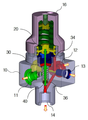
도 1은 본 발명에 따른 고압 레귤레이터를 부분 단면으로 나타내는 구성도
도 2는 본 발명에 따른 고압 레귤레이터의 주요부를 나타내는 모식도
도 3 및 도 4는 본 발명에 따른 레귤레이터에 밸브를 장착한 상태를 나타내는 구성도BRIEF DESCRIPTION OF THE DRAWINGS Fig. 1 is a configuration diagram showing a partial cross section of a high-voltage regulator according to the present invention; Fig.
FIG. 2 is a schematic diagram showing a main part of a high-voltage regulator according to the present invention.
3 and 4 are diagrams showing a state in which a valve is mounted on a regulator according to the present invention
이하, 첨부된 도면에 의거하여 본 발명의 실시예를 상세하게 설명하면 다음과 같다.Hereinafter, embodiments of the present invention will be described in detail with reference to the accompanying drawings.
본 발명은 차량의 연료 공급 압력을 조절하는 고압 레귤레이터에 관하여 제안한다. 특히, 수소 연료전지 자동차에서 최고 87.5㎫에 달하는 고압의 수소를 감압하여 설정된 압력으로 공급하는 레귤레이터를 대상으로 하지만 반드시 이에 국한되는 것은 아니다.The present invention proposes a high-pressure regulator for regulating the fuel supply pressure of a vehicle. In particular, the present invention is directed to a regulator for reducing the pressure of a high-pressure hydrogen up to 87.5 MPa in a hydrogen fuel cell vehicle and supplying it to a set pressure.
본 발명에 따르면 바디(10)가 축방향과 반경방향으로 다수의 포트를 형성한 중공 구조이다. 도 1을 기준으로 하면 바디(10)는 중심에 상하의 축방향으로 중공을 구비하면서 측면에 반경방향으로 입구포트(11), 출구포트(12), 센서포트(13)를 구비한다. 측면에는 상기한 포트 외에 장착을 위한 홀이 형성되고, 하단에는 밸브포트(14)가 형성된다. 입구포트(11), 센서포트(13), 밸브포트(14)는 중공과 직접 연통되는 반면 출구포트(12)는 출구홀(34)을 개재하여 중공에 연통된다.According to the present invention, the
이와 같이 바디(10)에 포트가 밀집적으로 배치되는 것은 레귤레이터의 경박단소 설계에 있어 중요한 요소이다.The arrangement of the ports densely in the
한편, 입구포트(11)의 수소(가스) 압력은 2.0~87.5㎫로 변동되지만 출구포트(12)에서 1.6㎫의 안정적인 유지가 가능하다. 센서포트(13)에는 수소의 출구압력을 검출하기 위한 센서가 결합된다.On the other hand, although the hydrogen (gas) pressure of the
본 발명의 세부 구성으로서, 상기 바디(10)는 알루미늄을 사용하여 표면에 다공질의 산화피막을 형성한 구조인 것을 특징으로 한다. 바디(10)의 소재는 SUS가 보편적이지만 수소 연료전지 자동차에 있어서 알루미늄이 선호된다. 다만, 경도, 내식성, 내마모성 등의 물성이 약하므로 산화피막의 표면처리를 거치는 것이 바람직하다. 일예로 알루미늄 양극산화법인 에마틀(EMATAL) 방식을 적용하면 SUS와 유사한 물성을 나타낸다.As a detailed configuration of the present invention, the
본 발명의 세부 구성으로서, 상기 바디(10)는 출구포트(12)와 밸브포트(14)를 경사진 경로로 연통하는 밸런스홀(36)을 구비하는 것을 특징으로 한다. 밸런스홀(36)은 입구압력에 따른 출구압력을 보상하기 위한 것으로서 축방향이나 반경방향이 아닌 경사진 방향으로 가공된다. 이에, 직교하는 2방향의 가공 및 되막기 위한 별도의 플러그가 배제되므로 원가절감의 효과가 있다.The
또, 본 발명에 따르면 피스톤(20)이 상기 바디(10)의 중공에 상하운동 가능하게 수용되는 구조이다. 피스톤(20)은 중공의 상측으로 배치되고 상부에서 스프링(26)에 의한 탄성력을 받는다. 피스톤(20)에 작용하는 탄성력은 조절볼트(24)로 가변되어 출구압력을 변동할 수 있다. 조절볼트(24)와 스프링(26)은 바디(10)의 상측에 결합되는 커버(16)에 설치된다.According to the present invention, the piston (20) is accommodated in the hollow of the body (10) so as to be movable up and down. The piston (20) is arranged on the upper side of the hollow and receives elastic force by the spring (26) at the upper part. The elastic force acting on the
또, 본 발명에 따르면 시트(30)가 상기 바디(10)의 중공에 오리피스(31)를 형성하도록 수용되는 구조이다. 시트(30)는 바디(10)의 중공의 중간 부분에 고정되며, 중앙에 오리피스(31)를 형성하기 위한 통공을 지닌다. 시트(30)의 상하요동을 구속하기 위해 상측으로 가이드(32)가 설치된다. 가이드(32)는 오리피스(31)를 통하여 유입되는 고압 수소의 균일한 확산을 위해 원추형 내면을 구비한다.According to the present invention, the
본 발명의 세부 구성으로서, 상기 시트(30)는 PEEK(Polyetherethereketone) 소재를 사용하여 150℃ 이상에서 열처리된 것을 특징으로 한다. PEEK 재질은 엔지니어링 플라스틱으로서 금속과 유사한 강도, 내충격성, 내마모성을 가지면서 열처리를 포함한 가공성도 양호하다. 시트(30)에 150℃ 이상에서 열처리를 작용하면 기계가공 과정의 물성변화를 회복시킬 수 있다.As a detailed construction of the present invention, the
또, 본 발명에 따르면 스풀(40)이 상기 피스톤(20)과 시트(30)를 통과하도록 설치되고, 압력조절을 위한 상하운동을 수행하는 구조이다. 스풀(40)은 바디(10)의 중공에 동심상으로 상하운동 가능하게 배치되고, 중간에서 시트(30)를 통과하면서 오리피스(31)의 유로단면적을 변동한다. 스풀(40)의 상하운동은 축방향의 정수직 운동을 필수적으로 요구한다.According to the present invention, the spool (40) is installed to pass through the piston (20) and the seat (30), and performs a vertical movement for pressure control. The
본 발명의 세부 구성으로서, 상기 스풀(40)은 상부가이드(41)를 개재하여 스풀(40) 상에 수용되고, 상부가이드(41)와 하부가이드(42)의 중간에 중간가이드(43)를 구비하는 것을 특징으로 한다. 상부가이드(41)는 피스톤(20)에 슬라이딩 가능한 상태로 스풀(40)의 상단을 긴밀하게 지지한다. 하부가이드(42)는 실링에 슬라이딩 가능한 상태로 스풀(40)의 하단을 긴밀하게 지지한다. 중간가이드(43)는 시트(30)의 하측에서 바디(10)의 중공에 슬라이딩 가능한 상태로 스풀(40)의 중간을 긴밀하게 지지한다. 긴밀한 지지는 스풀(40)의 정수직 운동을 유도하기 위한 공차관리가 적용됨을 의미한다. 하부가이드(42)와 중간가이드(43) 사이에는 스풀(40)에 축방향 탄성력을 작용하는 스프링(46)이 설치된다.The
이때, 도 3에 나타내듯이 스풀(40)은 하단에서 밸런스홀(36)과 연통되는 구조상 축방향으로 출구압력을 받는다.At this time, as shown in FIG. 3, the
본 발명의 세부 구성으로서, 상기 바디(10)의 밸브포트(14)에 해압 기능을 위한 배기노즐(52)과 릴리프 기능을 위한 플란저시트(55)를 구비하는 것을 특징으로 한다. 밸브포트(14)에 결합되는 밸브(50)는 일체형의 몸체(51) 상에 형성되고 점검ㆍ교체를 위한 해압 기능과 이상 고압시 급속감압을 위한 릴리프 기능을 수행한다. 몸체(51)의 상측에는 플란저시트(55)가 스프링(56)을 개재하여 결합되고, 몸체(51)의 하측에는 배기노즐(52)이 락킹너트(53)를 개재하여 결합된다.As a detailed construction of the present invention, the
도 4에서, 출구포트(12)의 출구압력이 설정치를 초과하면 플란저시트(55)가 하향하여 배기노즐(52)로 수소를 배출한다. 락킹너트(53)를 어느 이상으로 풀면 스프링(56)의 탄성력이 축소되어 출구포트(12)의 압력을 해제할 수 있다.In Fig. 4, when the outlet pressure of the
본 발명은 기재된 실시예에 한정되는 것은 아니고, 본 발명의 사상 및 범위를 벗어나지 않고 다양하게 수정 및 변형할 수 있음은 이 기술의 분야에서 통상의 지식을 가진 자에게 자명하다. 따라서 그러한 변형예 또는 수정예들은 본 발명의 특허청구범위에 속한다 해야 할 것이다.It will be apparent to those skilled in the art that various modifications and variations can be made in the present invention without departing from the spirit and scope of the invention as defined by the appended claims. It is therefore intended that such variations and modifications fall within the scope of the appended claims.
10: 바디
11: 입구포트
12: 출구포트
13: 센서포트
14: 밸브포트
20: 피스톤
22: 요홈
24: 조절볼트
26, 46, 56: 스프링
30: 시트
31: 오리피스
32: 가이드
34: 출구홀
36: 밸런스홀
40: 스풀
41, 42, 43: 가이드
50: 밸브
51: 몸체
52: 배기노즐
53: 락킹너트
55: 플란저시트10: Body 11: Inlet port
12: Exit port 13: Sensor port
14: valve port 20: piston
22: groove 24: adjusting bolt
26, 46, 56: spring 30: sheet
31: Orifice 32: Guide
34: Exit hole 36: Balance hole
40:
50: valve 51: body
52: exhaust nozzle 53: locking nut
55: flanger sheet
Claims (6)
축방향과 반경방향으로 다수의 포트를 형성한 중공 구조의 바디(10);
상기 바디(10)의 중공에 상하운동 가능하게 수용되는 피스톤(20);
상기 바디(10)의 중공에 오리피스(31)를 형성하도록 수용되는 시트(30); 및
상기 피스톤(20)과 시트(30)를 통과하도록 설치되고, 압력조절을 위한 상하운동을 수행하는 스풀(40);을 포함하여 이루어지는 것을 특징으로 하는 수소 연료전지 차량의 고압 레귤레이터.1. A high-pressure regulator for regulating a fuel supply pressure of a vehicle, comprising:
A hollow body 10 having a plurality of ports in the axial and radial directions;
A piston 20 received in the hollow of the body 10 so as to be vertically movable;
A seat (30) received to form an orifice (31) in the hollow of the body (10); And
And a spool (40) installed to pass through the piston (20) and the seat (30) and performing up and down movement for pressure control.
상기 바디(10)는 알루미늄을 사용하여 표면에 다공질의 산화피막을 형성한 구조인 것을 특징으로 하는 수소 연료전지 차량의 고압 레귤레이터.The method according to claim 1,
Wherein the body (10) is a structure in which a porous oxide film is formed on the surface using aluminum.
상기 바디(10)는 출구포트(12)와 밸브포트(14)를 경사진 경로로 연통하는 밸런스홀(36)을 구비하는 것을 특징으로 하는 수소 연료전지 차량의 고압 레귤레이터.The method according to claim 1,
Wherein the body (10) has a balance hole (36) that communicates the outlet port (12) with the valve port (14) by an inclined path.
상기 시트(30)는 PEEK(Polyetherethereketone) 소재를 사용하여 150℃ 이상에서 열처리된 것을 특징으로 하는 수소 연료전지 차량의 고압 레귤레이터.The method according to claim 1,
Wherein the sheet (30) is heat-treated at 150 ° C or higher using a PEEK (Polyetheretherketone) material.
상기 스풀(40)은 상부가이드(41)를 개재하여 스풀(40) 상에 수용되고, 상부가이드(41)와 하부가이드(42)의 중간에 중간가이드(43)를 구비하는 것을 특징으로 하는 수소 연료전지 차량의 고압 레귤레이터.The method according to claim 1,
Characterized in that the spool (40) is accommodated on the spool (40) via an upper guide (41), and an intermediate guide (43) is provided between the upper guide (41) and the lower guide High voltage regulator of fuel cell vehicle.
상기 바디(10)의 밸브포트(14)에 해압 기능을 위한 배기노즐(52)과 릴리프 기능을 위한 플란저시트(55)를 구비하는 것을 특징으로 하는 수소 연료전지 차량의 고압 레귤레이터.The method according to claim 1,
Characterized in that the valve port (14) of the body (10) has an exhaust nozzle (52) for a pneumatic function and a flange seat (55) for a relief function.
Priority Applications (1)
| Application Number | Priority Date | Filing Date | Title |
|---|---|---|---|
| KR1020150182970A KR101808712B1 (en) | 2015-12-21 | 2015-12-21 | High pressure regulator for hydrogen fuel cell electric vehicle |
Applications Claiming Priority (1)
| Application Number | Priority Date | Filing Date | Title |
|---|---|---|---|
| KR1020150182970A KR101808712B1 (en) | 2015-12-21 | 2015-12-21 | High pressure regulator for hydrogen fuel cell electric vehicle |
Publications (2)
| Publication Number | Publication Date |
|---|---|
| KR20170074009A true KR20170074009A (en) | 2017-06-29 |
| KR101808712B1 KR101808712B1 (en) | 2017-12-14 |
Family
ID=59280257
Family Applications (1)
| Application Number | Title | Priority Date | Filing Date |
|---|---|---|---|
| KR1020150182970A KR101808712B1 (en) | 2015-12-21 | 2015-12-21 | High pressure regulator for hydrogen fuel cell electric vehicle |
Country Status (1)
| Country | Link |
|---|---|
| KR (1) | KR101808712B1 (en) |
Cited By (3)
| Publication number | Priority date | Publication date | Assignee | Title |
|---|---|---|---|---|
| KR20190074162A (en) | 2017-12-19 | 2019-06-27 | (주)모토닉 | Electronic regulator for 2-stage pressure reduction of hydrogen |
| KR102303016B1 (en) * | 2020-05-28 | 2021-09-15 | 주식회사평화발레오 | Pressure regulating device for FCEV |
| KR20220128820A (en) | 2021-03-15 | 2022-09-22 | 주식회사 세화하이테크 | Jig device for processing regulator body |
Families Citing this family (4)
| Publication number | Priority date | Publication date | Assignee | Title |
|---|---|---|---|---|
| KR102602414B1 (en) | 2018-09-18 | 2023-11-14 | 현대자동차주식회사 | Pressure regulator for fuel cell system |
| KR102165550B1 (en) * | 2019-01-30 | 2020-10-15 | (주)모토닉 | Pressure reduction shaft device for high pressure electronic regulator |
| KR20210032739A (en) | 2019-09-17 | 2021-03-25 | (주)모토닉 | Shut off valve and regulator with the same |
| KR20230084937A (en) | 2021-12-06 | 2023-06-13 | (주)모토닉 | Complex valve structure for hydrogen high pressure regulator |
-
2015
- 2015-12-21 KR KR1020150182970A patent/KR101808712B1/en active IP Right Grant
Cited By (3)
| Publication number | Priority date | Publication date | Assignee | Title |
|---|---|---|---|---|
| KR20190074162A (en) | 2017-12-19 | 2019-06-27 | (주)모토닉 | Electronic regulator for 2-stage pressure reduction of hydrogen |
| KR102303016B1 (en) * | 2020-05-28 | 2021-09-15 | 주식회사평화발레오 | Pressure regulating device for FCEV |
| KR20220128820A (en) | 2021-03-15 | 2022-09-22 | 주식회사 세화하이테크 | Jig device for processing regulator body |
Also Published As
| Publication number | Publication date |
|---|---|
| KR101808712B1 (en) | 2017-12-14 |
Similar Documents
| Publication | Publication Date | Title |
|---|---|---|
| KR101808712B1 (en) | High pressure regulator for hydrogen fuel cell electric vehicle | |
| US7341074B2 (en) | Multi-stage pressure regulator | |
| US9810327B2 (en) | Pressure reducing valve | |
| US9310810B2 (en) | Adjustable damping valve device | |
| US20080011361A1 (en) | High-Pressure Regulator | |
| US10760637B2 (en) | Adjustable damping valve device | |
| US9709994B2 (en) | Device for providing a fluid having regulated output pressure | |
| US8944089B2 (en) | Balanced valve port for fluid regulator | |
| CN110906034B (en) | Pressure regulator for fuel cell system | |
| JP6321128B2 (en) | Sealing structure of hydrogen fuel cell vehicle regulator | |
| JP2017079026A (en) | Pressure adjustment valve | |
| KR20130086966A (en) | Flow amount control apparatus | |
| KR102141895B1 (en) | Electronic regulator for 2-stage pressure reduction of hydrogen | |
| WO2013136914A1 (en) | Control valve | |
| JP2016136304A (en) | Pressure adjustment valve | |
| EP2708970B1 (en) | Pressure regulator | |
| JP2006003943A (en) | Depressurizing device and depressurizing system | |
| KR102165550B1 (en) | Pressure reduction shaft device for high pressure electronic regulator | |
| JP2007148641A (en) | Regulator for fluid | |
| KR101982592B1 (en) | Regulator | |
| JP2016184257A (en) | Pressure control valve | |
| KR20230168847A (en) | Sensitivity adjustable high pressure regulator | |
| RU2329158C2 (en) | Vehicle floor level adjuster | |
| JP2017051882A (en) | Filter fitting structure and pressure regulating valve | |
| US9684315B2 (en) | Control valve |
Legal Events
| Date | Code | Title | Description |
|---|---|---|---|
| A201 | Request for examination | ||
| E902 | Notification of reason for refusal | ||
| E701 | Decision to grant or registration of patent right | ||
| GRNT | Written decision to grant |