KR20170049538A - Grain boundary engineering - Google Patents
Grain boundary engineering Download PDFInfo
- Publication number
- KR20170049538A KR20170049538A KR1020177006952A KR20177006952A KR20170049538A KR 20170049538 A KR20170049538 A KR 20170049538A KR 1020177006952 A KR1020177006952 A KR 1020177006952A KR 20177006952 A KR20177006952 A KR 20177006952A KR 20170049538 A KR20170049538 A KR 20170049538A
- Authority
- KR
- South Korea
- Prior art keywords
- powder
- rare earth
- magnet
- magnetic
- produce
- Prior art date
- Legal status (The legal status is an assumption and is not a legal conclusion. Google has not performed a legal analysis and makes no representation as to the accuracy of the status listed.)
- Withdrawn
Links
- 239000000843 powder Substances 0.000 claims abstract description 235
- 239000000463 material Substances 0.000 claims abstract description 209
- 238000000034 method Methods 0.000 claims abstract description 186
- 239000000654 additive Substances 0.000 claims abstract description 169
- 230000000996 additive effect Effects 0.000 claims abstract description 154
- 239000000956 alloy Substances 0.000 claims abstract description 147
- 229910045601 alloy Inorganic materials 0.000 claims abstract description 146
- 229910001172 neodymium magnet Inorganic materials 0.000 claims abstract description 145
- 229910052761 rare earth metal Inorganic materials 0.000 claims abstract description 134
- 150000002910 rare earth metals Chemical class 0.000 claims abstract description 121
- 238000002156 mixing Methods 0.000 claims abstract description 113
- 239000002245 particle Substances 0.000 claims abstract description 75
- 238000002844 melting Methods 0.000 claims abstract description 45
- 230000008018 melting Effects 0.000 claims abstract description 44
- 238000005245 sintering Methods 0.000 claims abstract description 44
- 230000008569 process Effects 0.000 claims description 116
- 229910052779 Neodymium Inorganic materials 0.000 claims description 96
- 229910052692 Dysprosium Inorganic materials 0.000 claims description 80
- 229910052777 Praseodymium Inorganic materials 0.000 claims description 76
- 229910052742 iron Inorganic materials 0.000 claims description 67
- 229910052760 oxygen Inorganic materials 0.000 claims description 35
- QVGXLLKOCUKJST-UHFFFAOYSA-N atomic oxygen Chemical compound [O] QVGXLLKOCUKJST-UHFFFAOYSA-N 0.000 claims description 31
- 239000001301 oxygen Substances 0.000 claims description 31
- 230000005389 magnetism Effects 0.000 claims description 21
- 238000004519 manufacturing process Methods 0.000 claims description 20
- 230000001965 increasing effect Effects 0.000 claims description 16
- 239000013078 crystal Substances 0.000 claims description 11
- 238000000227 grinding Methods 0.000 claims description 3
- 229910052738 indium Inorganic materials 0.000 claims description 3
- 238000005266 casting Methods 0.000 claims description 2
- 229910052709 silver Inorganic materials 0.000 claims 1
- 239000004332 silver Substances 0.000 claims 1
- 238000003860 storage Methods 0.000 abstract description 26
- 238000004590 computer program Methods 0.000 abstract description 16
- 238000003825 pressing Methods 0.000 abstract description 3
- XEEYBQQBJWHFJM-UHFFFAOYSA-N iron Substances [Fe] XEEYBQQBJWHFJM-UHFFFAOYSA-N 0.000 description 187
- 239000010949 copper Substances 0.000 description 144
- 239000000047 product Substances 0.000 description 103
- UFHFLCQGNIYNRP-UHFFFAOYSA-N Hydrogen Chemical compound [H][H] UFHFLCQGNIYNRP-UHFFFAOYSA-N 0.000 description 89
- 239000001257 hydrogen Substances 0.000 description 81
- 229910052739 hydrogen Inorganic materials 0.000 description 81
- 229910052802 copper Inorganic materials 0.000 description 65
- 239000007789 gas Substances 0.000 description 56
- 239000000203 mixture Substances 0.000 description 52
- 238000006243 chemical reaction Methods 0.000 description 49
- 150000001875 compounds Chemical class 0.000 description 38
- 230000007704 transition Effects 0.000 description 32
- 239000002243 precursor Substances 0.000 description 28
- 239000000696 magnetic material Substances 0.000 description 25
- 239000012298 atmosphere Substances 0.000 description 23
- 238000012545 processing Methods 0.000 description 23
- 239000012467 final product Substances 0.000 description 22
- 239000007858 starting material Substances 0.000 description 22
- 229910052799 carbon Inorganic materials 0.000 description 21
- 239000002699 waste material Substances 0.000 description 21
- 238000001816 cooling Methods 0.000 description 19
- 239000011261 inert gas Substances 0.000 description 18
- 238000010902 jet-milling Methods 0.000 description 18
- OKTJSMMVPCPJKN-UHFFFAOYSA-N Carbon Chemical compound [C] OKTJSMMVPCPJKN-UHFFFAOYSA-N 0.000 description 16
- 239000002131 composite material Substances 0.000 description 16
- 238000002347 injection Methods 0.000 description 15
- 239000007924 injection Substances 0.000 description 15
- 238000007726 management method Methods 0.000 description 14
- 230000002441 reversible effect Effects 0.000 description 14
- 238000013467 fragmentation Methods 0.000 description 13
- 238000006062 fragmentation reaction Methods 0.000 description 13
- 239000007921 spray Substances 0.000 description 13
- 238000012546 transfer Methods 0.000 description 13
- 229910052771 Terbium Inorganic materials 0.000 description 11
- 230000007797 corrosion Effects 0.000 description 11
- 238000005260 corrosion Methods 0.000 description 11
- 230000015572 biosynthetic process Effects 0.000 description 10
- 238000003801 milling Methods 0.000 description 10
- 239000002019 doping agent Substances 0.000 description 9
- XKRFYHLGVUSROY-UHFFFAOYSA-N Argon Chemical compound [Ar] XKRFYHLGVUSROY-UHFFFAOYSA-N 0.000 description 8
- RYGMFSIKBFXOCR-UHFFFAOYSA-N Copper Chemical compound [Cu] RYGMFSIKBFXOCR-UHFFFAOYSA-N 0.000 description 8
- 229910052786 argon Inorganic materials 0.000 description 8
- 238000000889 atomisation Methods 0.000 description 8
- 238000005516 engineering process Methods 0.000 description 8
- 238000000265 homogenisation Methods 0.000 description 8
- 238000005984 hydrogenation reaction Methods 0.000 description 8
- 229910052698 phosphorus Inorganic materials 0.000 description 8
- 230000002829 reductive effect Effects 0.000 description 8
- 238000005275 alloying Methods 0.000 description 7
- 239000006249 magnetic particle Substances 0.000 description 7
- XLYOFNOQVPJJNP-UHFFFAOYSA-N water Substances O XLYOFNOQVPJJNP-UHFFFAOYSA-N 0.000 description 7
- 150000004678 hydrides Chemical class 0.000 description 6
- 239000000314 lubricant Substances 0.000 description 6
- 239000000155 melt Substances 0.000 description 6
- 238000005204 segregation Methods 0.000 description 6
- 238000007873 sieving Methods 0.000 description 6
- 239000000126 substance Substances 0.000 description 6
- 238000004891 communication Methods 0.000 description 5
- KBQHZAAAGSGFKK-UHFFFAOYSA-N dysprosium atom Chemical compound [Dy] KBQHZAAAGSGFKK-UHFFFAOYSA-N 0.000 description 5
- 230000004907 flux Effects 0.000 description 5
- 238000000926 separation method Methods 0.000 description 5
- 229910017061 Fe Co Inorganic materials 0.000 description 4
- PNEYBMLMFCGWSK-UHFFFAOYSA-N aluminium oxide Inorganic materials [O-2].[O-2].[O-2].[Al+3].[Al+3] PNEYBMLMFCGWSK-UHFFFAOYSA-N 0.000 description 4
- 229910052796 boron Inorganic materials 0.000 description 4
- 230000007547 defect Effects 0.000 description 4
- 238000010586 diagram Methods 0.000 description 4
- 238000009792 diffusion process Methods 0.000 description 4
- 238000009826 distribution Methods 0.000 description 4
- 150000002431 hydrogen Chemical class 0.000 description 4
- 230000006698 induction Effects 0.000 description 4
- 230000006911 nucleation Effects 0.000 description 4
- 238000010899 nucleation Methods 0.000 description 4
- -1 phosphorus compound Chemical class 0.000 description 4
- 238000005086 pumping Methods 0.000 description 4
- 239000002994 raw material Substances 0.000 description 4
- 238000005507 spraying Methods 0.000 description 4
- 230000032258 transport Effects 0.000 description 4
- 229910052726 zirconium Inorganic materials 0.000 description 4
- 229910052772 Samarium Inorganic materials 0.000 description 3
- 239000003570 air Substances 0.000 description 3
- 229910052782 aluminium Inorganic materials 0.000 description 3
- 239000012300 argon atmosphere Substances 0.000 description 3
- 210000003323 beak Anatomy 0.000 description 3
- 230000008901 benefit Effects 0.000 description 3
- 238000011109 contamination Methods 0.000 description 3
- 230000001276 controlling effect Effects 0.000 description 3
- 230000007423 decrease Effects 0.000 description 3
- 239000012530 fluid Substances 0.000 description 3
- 238000010438 heat treatment Methods 0.000 description 3
- 229910052734 helium Inorganic materials 0.000 description 3
- 238000000713 high-energy ball milling Methods 0.000 description 3
- 230000003993 interaction Effects 0.000 description 3
- 229910052746 lanthanum Inorganic materials 0.000 description 3
- 230000000670 limiting effect Effects 0.000 description 3
- 239000011159 matrix material Substances 0.000 description 3
- 230000004048 modification Effects 0.000 description 3
- 238000012986 modification Methods 0.000 description 3
- 229910052757 nitrogen Inorganic materials 0.000 description 3
- 230000003287 optical effect Effects 0.000 description 3
- 238000002360 preparation method Methods 0.000 description 3
- 238000012360 testing method Methods 0.000 description 3
- 229910052723 transition metal Inorganic materials 0.000 description 3
- IJGRMHOSHXDMSA-UHFFFAOYSA-N Atomic nitrogen Chemical compound N#N IJGRMHOSHXDMSA-UHFFFAOYSA-N 0.000 description 2
- 229910052684 Cerium Inorganic materials 0.000 description 2
- 229910002546 FeCo Inorganic materials 0.000 description 2
- 229910052688 Gadolinium Inorganic materials 0.000 description 2
- 229910052689 Holmium Inorganic materials 0.000 description 2
- 229910052769 Ytterbium Inorganic materials 0.000 description 2
- QCWXUUIWCKQGHC-UHFFFAOYSA-N Zirconium Chemical compound [Zr] QCWXUUIWCKQGHC-UHFFFAOYSA-N 0.000 description 2
- MCMNRKCIXSYSNV-UHFFFAOYSA-N Zirconium dioxide Chemical compound O=[Zr]=O MCMNRKCIXSYSNV-UHFFFAOYSA-N 0.000 description 2
- 230000009471 action Effects 0.000 description 2
- 150000001408 amides Chemical class 0.000 description 2
- 239000011324 bead Substances 0.000 description 2
- 230000009286 beneficial effect Effects 0.000 description 2
- 239000007795 chemical reaction product Substances 0.000 description 2
- 239000003638 chemical reducing agent Substances 0.000 description 2
- 238000010960 commercial process Methods 0.000 description 2
- 238000000748 compression moulding Methods 0.000 description 2
- 230000003247 decreasing effect Effects 0.000 description 2
- 238000013461 design Methods 0.000 description 2
- 238000000921 elemental analysis Methods 0.000 description 2
- 229910052733 gallium Inorganic materials 0.000 description 2
- 230000005484 gravity Effects 0.000 description 2
- 238000010316 high energy milling Methods 0.000 description 2
- 239000008240 homogeneous mixture Substances 0.000 description 2
- 238000011068 loading method Methods 0.000 description 2
- 239000006247 magnetic powder Substances 0.000 description 2
- 230000005415 magnetization Effects 0.000 description 2
- 229910001092 metal group alloy Inorganic materials 0.000 description 2
- QEFYFXOXNSNQGX-UHFFFAOYSA-N neodymium atom Chemical compound [Nd] QEFYFXOXNSNQGX-UHFFFAOYSA-N 0.000 description 2
- 230000035699 permeability Effects 0.000 description 2
- PUDIUYLPXJFUGB-UHFFFAOYSA-N praseodymium atom Chemical compound [Pr] PUDIUYLPXJFUGB-UHFFFAOYSA-N 0.000 description 2
- 230000001737 promoting effect Effects 0.000 description 2
- 238000010926 purge Methods 0.000 description 2
- 238000011002 quantification Methods 0.000 description 2
- 229910001404 rare earth metal oxide Inorganic materials 0.000 description 2
- 229910052717 sulfur Inorganic materials 0.000 description 2
- 238000009827 uniform distribution Methods 0.000 description 2
- WRIDQFICGBMAFQ-UHFFFAOYSA-N (E)-8-Octadecenoic acid Natural products CCCCCCCCCC=CCCCCCCC(O)=O WRIDQFICGBMAFQ-UHFFFAOYSA-N 0.000 description 1
- LQJBNNIYVWPHFW-UHFFFAOYSA-N 20:1omega9c fatty acid Natural products CCCCCCCCCCC=CCCCCCCCC(O)=O LQJBNNIYVWPHFW-UHFFFAOYSA-N 0.000 description 1
- QSBYPNXLFMSGKH-UHFFFAOYSA-N 9-Heptadecensaeure Natural products CCCCCCCC=CCCCCCCCC(O)=O QSBYPNXLFMSGKH-UHFFFAOYSA-N 0.000 description 1
- 229910000521 B alloy Inorganic materials 0.000 description 1
- ZOXJGFHDIHLPTG-UHFFFAOYSA-N Boron Chemical compound [B] ZOXJGFHDIHLPTG-UHFFFAOYSA-N 0.000 description 1
- 229910020674 Co—B Inorganic materials 0.000 description 1
- 229910017827 Cu—Fe Inorganic materials 0.000 description 1
- ZQPPMHVWECSIRJ-UHFFFAOYSA-N Oleic acid Natural products CCCCCCCCC=CCCCCCCCC(O)=O ZQPPMHVWECSIRJ-UHFFFAOYSA-N 0.000 description 1
- 239000005642 Oleic acid Substances 0.000 description 1
- QJVKUMXDEUEQLH-UHFFFAOYSA-N [B].[Fe].[Nd] Chemical compound [B].[Fe].[Nd] QJVKUMXDEUEQLH-UHFFFAOYSA-N 0.000 description 1
- 238000010521 absorption reaction Methods 0.000 description 1
- 239000012080 ambient air Substances 0.000 description 1
- 238000004458 analytical method Methods 0.000 description 1
- 238000000137 annealing Methods 0.000 description 1
- 238000010314 arc-melting process Methods 0.000 description 1
- 238000000498 ball milling Methods 0.000 description 1
- 239000011230 binding agent Substances 0.000 description 1
- 230000033228 biological regulation Effects 0.000 description 1
- 230000005540 biological transmission Effects 0.000 description 1
- 238000007664 blowing Methods 0.000 description 1
- 230000015556 catabolic process Effects 0.000 description 1
- 230000008859 change Effects 0.000 description 1
- 229910017052 cobalt Inorganic materials 0.000 description 1
- 239000010941 cobalt Substances 0.000 description 1
- GUTLYIVDDKVIGB-UHFFFAOYSA-N cobalt atom Chemical compound [Co] GUTLYIVDDKVIGB-UHFFFAOYSA-N 0.000 description 1
- PTVDYARBVCBHSL-UHFFFAOYSA-N copper;hydrate Chemical compound O.[Cu] PTVDYARBVCBHSL-UHFFFAOYSA-N 0.000 description 1
- 238000002425 crystallisation Methods 0.000 description 1
- 230000008025 crystallization Effects 0.000 description 1
- 238000005520 cutting process Methods 0.000 description 1
- 230000007123 defense Effects 0.000 description 1
- 230000007812 deficiency Effects 0.000 description 1
- 238000006731 degradation reaction Methods 0.000 description 1
- 238000011161 development Methods 0.000 description 1
- 235000014113 dietary fatty acids Nutrition 0.000 description 1
- 238000005538 encapsulation Methods 0.000 description 1
- 238000005265 energy consumption Methods 0.000 description 1
- 238000012407 engineering method Methods 0.000 description 1
- 230000007613 environmental effect Effects 0.000 description 1
- 230000003628 erosive effect Effects 0.000 description 1
- 230000005496 eutectics Effects 0.000 description 1
- 230000001747 exhibiting effect Effects 0.000 description 1
- 238000002474 experimental method Methods 0.000 description 1
- 238000013213 extrapolation Methods 0.000 description 1
- 229930195729 fatty acid Natural products 0.000 description 1
- 239000000194 fatty acid Substances 0.000 description 1
- 150000004665 fatty acids Chemical class 0.000 description 1
- 238000011049 filling Methods 0.000 description 1
- 239000010419 fine particle Substances 0.000 description 1
- 239000006260 foam Substances 0.000 description 1
- 238000009472 formulation Methods 0.000 description 1
- 239000012634 fragment Substances 0.000 description 1
- 239000000446 fuel Substances 0.000 description 1
- 230000006870 function Effects 0.000 description 1
- 230000009036 growth inhibition Effects 0.000 description 1
- 230000002706 hydrostatic effect Effects 0.000 description 1
- 230000006872 improvement Effects 0.000 description 1
- 238000011065 in-situ storage Methods 0.000 description 1
- 230000001939 inductive effect Effects 0.000 description 1
- 230000004941 influx Effects 0.000 description 1
- QXJSBBXBKPUZAA-UHFFFAOYSA-N isooleic acid Natural products CCCCCCCC=CCCCCCCCCC(O)=O QXJSBBXBKPUZAA-UHFFFAOYSA-N 0.000 description 1
- 239000007788 liquid Substances 0.000 description 1
- 239000004973 liquid crystal related substance Substances 0.000 description 1
- 238000005461 lubrication Methods 0.000 description 1
- 238000002595 magnetic resonance imaging Methods 0.000 description 1
- 239000006148 magnetic separator Substances 0.000 description 1
- 230000007246 mechanism Effects 0.000 description 1
- 238000010309 melting process Methods 0.000 description 1
- 239000003607 modifier Substances 0.000 description 1
- 229910052750 molybdenum Inorganic materials 0.000 description 1
- 238000000465 moulding Methods 0.000 description 1
- 229910052754 neon Inorganic materials 0.000 description 1
- 229910052759 nickel Inorganic materials 0.000 description 1
- 229910052758 niobium Inorganic materials 0.000 description 1
- 150000002825 nitriles Chemical class 0.000 description 1
- FATBGEAMYMYZAF-KTKRTIGZSA-N oleamide Chemical compound CCCCCCCC\C=C/CCCCCCCC(N)=O FATBGEAMYMYZAF-KTKRTIGZSA-N 0.000 description 1
- ZQPPMHVWECSIRJ-KTKRTIGZSA-N oleic acid Chemical compound CCCCCCCC\C=C/CCCCCCCC(O)=O ZQPPMHVWECSIRJ-KTKRTIGZSA-N 0.000 description 1
- FATBGEAMYMYZAF-UHFFFAOYSA-N oleicacidamide-heptaglycolether Natural products CCCCCCCCC=CCCCCCCCC(N)=O FATBGEAMYMYZAF-UHFFFAOYSA-N 0.000 description 1
- 239000007800 oxidant agent Substances 0.000 description 1
- 230000036961 partial effect Effects 0.000 description 1
- 239000013618 particulate matter Substances 0.000 description 1
- 238000005192 partition Methods 0.000 description 1
- 230000035515 penetration Effects 0.000 description 1
- 230000010412 perfusion Effects 0.000 description 1
- 230000002093 peripheral effect Effects 0.000 description 1
- 239000011574 phosphorus Substances 0.000 description 1
- 230000000704 physical effect Effects 0.000 description 1
- 238000009725 powder blending Methods 0.000 description 1
- 238000004886 process control Methods 0.000 description 1
- 238000003672 processing method Methods 0.000 description 1
- 230000002685 pulmonary effect Effects 0.000 description 1
- 238000000197 pyrolysis Methods 0.000 description 1
- 230000002285 radioactive effect Effects 0.000 description 1
- 238000004064 recycling Methods 0.000 description 1
- 230000009467 reduction Effects 0.000 description 1
- 230000001105 regulatory effect Effects 0.000 description 1
- 230000004044 response Effects 0.000 description 1
- 229920006395 saturated elastomer Polymers 0.000 description 1
- 238000010963 scalable process Methods 0.000 description 1
- 239000004065 semiconductor Substances 0.000 description 1
- 230000001953 sensory effect Effects 0.000 description 1
- 239000011343 solid material Substances 0.000 description 1
- 238000007711 solidification Methods 0.000 description 1
- 230000008023 solidification Effects 0.000 description 1
- 229910000601 superalloy Inorganic materials 0.000 description 1
- 230000001629 suppression Effects 0.000 description 1
- 230000026676 system process Effects 0.000 description 1
- GZCRRIHWUXGPOV-UHFFFAOYSA-N terbium atom Chemical compound [Tb] GZCRRIHWUXGPOV-UHFFFAOYSA-N 0.000 description 1
- 229910052719 titanium Inorganic materials 0.000 description 1
- 239000011882 ultra-fine particle Substances 0.000 description 1
- 229910052720 vanadium Inorganic materials 0.000 description 1
- 230000000007 visual effect Effects 0.000 description 1
- 229910052727 yttrium Inorganic materials 0.000 description 1
- XOOUIPVCVHRTMJ-UHFFFAOYSA-L zinc stearate Chemical compound [Zn+2].CCCCCCCCCCCCCCCCCC([O-])=O.CCCCCCCCCCCCCCCCCC([O-])=O XOOUIPVCVHRTMJ-UHFFFAOYSA-L 0.000 description 1
Images


Classifications
-
- B22F1/0055—
-
- B—PERFORMING OPERATIONS; TRANSPORTING
- B22—CASTING; POWDER METALLURGY
- B22F—WORKING METALLIC POWDER; MANUFACTURE OF ARTICLES FROM METALLIC POWDER; MAKING METALLIC POWDER; APPARATUS OR DEVICES SPECIALLY ADAPTED FOR METALLIC POWDER
- B22F3/00—Manufacture of workpieces or articles from metallic powder characterised by the manner of compacting or sintering; Apparatus specially adapted therefor ; Presses and furnaces
- B22F3/12—Both compacting and sintering
- B22F3/16—Both compacting and sintering in successive or repeated steps
-
- B—PERFORMING OPERATIONS; TRANSPORTING
- B22—CASTING; POWDER METALLURGY
- B22F—WORKING METALLIC POWDER; MANUFACTURE OF ARTICLES FROM METALLIC POWDER; MAKING METALLIC POWDER; APPARATUS OR DEVICES SPECIALLY ADAPTED FOR METALLIC POWDER
- B22F3/00—Manufacture of workpieces or articles from metallic powder characterised by the manner of compacting or sintering; Apparatus specially adapted therefor ; Presses and furnaces
- B22F3/24—After-treatment of workpieces or articles
-
- B—PERFORMING OPERATIONS; TRANSPORTING
- B22—CASTING; POWDER METALLURGY
- B22F—WORKING METALLIC POWDER; MANUFACTURE OF ARTICLES FROM METALLIC POWDER; MAKING METALLIC POWDER; APPARATUS OR DEVICES SPECIALLY ADAPTED FOR METALLIC POWDER
- B22F9/00—Making metallic powder or suspensions thereof
- B22F9/02—Making metallic powder or suspensions thereof using physical processes
- B22F9/023—Hydrogen absorption
-
- B—PERFORMING OPERATIONS; TRANSPORTING
- B22—CASTING; POWDER METALLURGY
- B22F—WORKING METALLIC POWDER; MANUFACTURE OF ARTICLES FROM METALLIC POWDER; MAKING METALLIC POWDER; APPARATUS OR DEVICES SPECIALLY ADAPTED FOR METALLIC POWDER
- B22F9/00—Making metallic powder or suspensions thereof
- B22F9/02—Making metallic powder or suspensions thereof using physical processes
- B22F9/04—Making metallic powder or suspensions thereof using physical processes starting from solid material, e.g. by crushing, grinding or milling
-
- B—PERFORMING OPERATIONS; TRANSPORTING
- B22—CASTING; POWDER METALLURGY
- B22F—WORKING METALLIC POWDER; MANUFACTURE OF ARTICLES FROM METALLIC POWDER; MAKING METALLIC POWDER; APPARATUS OR DEVICES SPECIALLY ADAPTED FOR METALLIC POWDER
- B22F9/00—Making metallic powder or suspensions thereof
- B22F9/02—Making metallic powder or suspensions thereof using physical processes
- B22F9/06—Making metallic powder or suspensions thereof using physical processes starting from liquid material
- B22F9/08—Making metallic powder or suspensions thereof using physical processes starting from liquid material by casting, e.g. through sieves or in water, by atomising or spraying
-
- C—CHEMISTRY; METALLURGY
- C22—METALLURGY; FERROUS OR NON-FERROUS ALLOYS; TREATMENT OF ALLOYS OR NON-FERROUS METALS
- C22C—ALLOYS
- C22C1/00—Making non-ferrous alloys
- C22C1/04—Making non-ferrous alloys by powder metallurgy
- C22C1/0433—Nickel- or cobalt-based alloys
- C22C1/0441—Alloys based on intermetallic compounds of the type rare earth - Co, Ni
-
- C—CHEMISTRY; METALLURGY
- C22—METALLURGY; FERROUS OR NON-FERROUS ALLOYS; TREATMENT OF ALLOYS OR NON-FERROUS METALS
- C22C—ALLOYS
- C22C28/00—Alloys based on a metal not provided for in groups C22C5/00 - C22C27/00
-
- C—CHEMISTRY; METALLURGY
- C22—METALLURGY; FERROUS OR NON-FERROUS ALLOYS; TREATMENT OF ALLOYS OR NON-FERROUS METALS
- C22C—ALLOYS
- C22C33/00—Making ferrous alloys
- C22C33/02—Making ferrous alloys by powder metallurgy
- C22C33/0257—Making ferrous alloys by powder metallurgy characterised by the range of the alloying elements
- C22C33/0278—Making ferrous alloys by powder metallurgy characterised by the range of the alloying elements with at least one alloying element having a minimum content above 5%
-
- C—CHEMISTRY; METALLURGY
- C22—METALLURGY; FERROUS OR NON-FERROUS ALLOYS; TREATMENT OF ALLOYS OR NON-FERROUS METALS
- C22C—ALLOYS
- C22C38/00—Ferrous alloys, e.g. steel alloys
- C22C38/002—Ferrous alloys, e.g. steel alloys containing In, Mg, or other elements not provided for in one single group C22C38/001 - C22C38/60
-
- C—CHEMISTRY; METALLURGY
- C22—METALLURGY; FERROUS OR NON-FERROUS ALLOYS; TREATMENT OF ALLOYS OR NON-FERROUS METALS
- C22C—ALLOYS
- C22C38/00—Ferrous alloys, e.g. steel alloys
- C22C38/005—Ferrous alloys, e.g. steel alloys containing rare earths, i.e. Sc, Y, Lanthanides
-
- C—CHEMISTRY; METALLURGY
- C22—METALLURGY; FERROUS OR NON-FERROUS ALLOYS; TREATMENT OF ALLOYS OR NON-FERROUS METALS
- C22C—ALLOYS
- C22C38/00—Ferrous alloys, e.g. steel alloys
- C22C38/06—Ferrous alloys, e.g. steel alloys containing aluminium
-
- C—CHEMISTRY; METALLURGY
- C22—METALLURGY; FERROUS OR NON-FERROUS ALLOYS; TREATMENT OF ALLOYS OR NON-FERROUS METALS
- C22C—ALLOYS
- C22C38/00—Ferrous alloys, e.g. steel alloys
- C22C38/10—Ferrous alloys, e.g. steel alloys containing cobalt
-
- C—CHEMISTRY; METALLURGY
- C22—METALLURGY; FERROUS OR NON-FERROUS ALLOYS; TREATMENT OF ALLOYS OR NON-FERROUS METALS
- C22C—ALLOYS
- C22C38/00—Ferrous alloys, e.g. steel alloys
- C22C38/14—Ferrous alloys, e.g. steel alloys containing titanium or zirconium
-
- C—CHEMISTRY; METALLURGY
- C22—METALLURGY; FERROUS OR NON-FERROUS ALLOYS; TREATMENT OF ALLOYS OR NON-FERROUS METALS
- C22C—ALLOYS
- C22C38/00—Ferrous alloys, e.g. steel alloys
- C22C38/16—Ferrous alloys, e.g. steel alloys containing copper
-
- H—ELECTRICITY
- H01—ELECTRIC ELEMENTS
- H01F—MAGNETS; INDUCTANCES; TRANSFORMERS; SELECTION OF MATERIALS FOR THEIR MAGNETIC PROPERTIES
- H01F1/00—Magnets or magnetic bodies characterised by the magnetic materials therefor; Selection of materials for their magnetic properties
- H01F1/01—Magnets or magnetic bodies characterised by the magnetic materials therefor; Selection of materials for their magnetic properties of inorganic materials
- H01F1/03—Magnets or magnetic bodies characterised by the magnetic materials therefor; Selection of materials for their magnetic properties of inorganic materials characterised by their coercivity
- H01F1/0302—Magnets or magnetic bodies characterised by the magnetic materials therefor; Selection of materials for their magnetic properties of inorganic materials characterised by their coercivity characterised by unspecified or heterogeneous hardness or specially adapted for magnetic hardness transitions
- H01F1/0306—Metals or alloys, e.g. LAVES phase alloys of the MgCu2-type
-
- H—ELECTRICITY
- H01—ELECTRIC ELEMENTS
- H01F—MAGNETS; INDUCTANCES; TRANSFORMERS; SELECTION OF MATERIALS FOR THEIR MAGNETIC PROPERTIES
- H01F1/00—Magnets or magnetic bodies characterised by the magnetic materials therefor; Selection of materials for their magnetic properties
- H01F1/01—Magnets or magnetic bodies characterised by the magnetic materials therefor; Selection of materials for their magnetic properties of inorganic materials
- H01F1/03—Magnets or magnetic bodies characterised by the magnetic materials therefor; Selection of materials for their magnetic properties of inorganic materials characterised by their coercivity
- H01F1/032—Magnets or magnetic bodies characterised by the magnetic materials therefor; Selection of materials for their magnetic properties of inorganic materials characterised by their coercivity of hard-magnetic materials
- H01F1/04—Magnets or magnetic bodies characterised by the magnetic materials therefor; Selection of materials for their magnetic properties of inorganic materials characterised by their coercivity of hard-magnetic materials metals or alloys
- H01F1/047—Alloys characterised by their composition
- H01F1/053—Alloys characterised by their composition containing rare earth metals
- H01F1/055—Alloys characterised by their composition containing rare earth metals and magnetic transition metals, e.g. SmCo5
- H01F1/057—Alloys characterised by their composition containing rare earth metals and magnetic transition metals, e.g. SmCo5 and IIIa elements, e.g. Nd2Fe14B
- H01F1/0571—Alloys characterised by their composition containing rare earth metals and magnetic transition metals, e.g. SmCo5 and IIIa elements, e.g. Nd2Fe14B in the form of particles, e.g. rapid quenched powders or ribbon flakes
- H01F1/0575—Alloys characterised by their composition containing rare earth metals and magnetic transition metals, e.g. SmCo5 and IIIa elements, e.g. Nd2Fe14B in the form of particles, e.g. rapid quenched powders or ribbon flakes pressed, sintered or bonded together
- H01F1/0577—Alloys characterised by their composition containing rare earth metals and magnetic transition metals, e.g. SmCo5 and IIIa elements, e.g. Nd2Fe14B in the form of particles, e.g. rapid quenched powders or ribbon flakes pressed, sintered or bonded together sintered
-
- H—ELECTRICITY
- H01—ELECTRIC ELEMENTS
- H01F—MAGNETS; INDUCTANCES; TRANSFORMERS; SELECTION OF MATERIALS FOR THEIR MAGNETIC PROPERTIES
- H01F41/00—Apparatus or processes specially adapted for manufacturing or assembling magnets, inductances or transformers; Apparatus or processes specially adapted for manufacturing materials characterised by their magnetic properties
- H01F41/02—Apparatus or processes specially adapted for manufacturing or assembling magnets, inductances or transformers; Apparatus or processes specially adapted for manufacturing materials characterised by their magnetic properties for manufacturing cores, coils, or magnets
- H01F41/0253—Apparatus or processes specially adapted for manufacturing or assembling magnets, inductances or transformers; Apparatus or processes specially adapted for manufacturing materials characterised by their magnetic properties for manufacturing cores, coils, or magnets for manufacturing permanent magnets
- H01F41/0266—Moulding; Pressing
-
- H—ELECTRICITY
- H01—ELECTRIC ELEMENTS
- H01F—MAGNETS; INDUCTANCES; TRANSFORMERS; SELECTION OF MATERIALS FOR THEIR MAGNETIC PROPERTIES
- H01F41/00—Apparatus or processes specially adapted for manufacturing or assembling magnets, inductances or transformers; Apparatus or processes specially adapted for manufacturing materials characterised by their magnetic properties
- H01F41/02—Apparatus or processes specially adapted for manufacturing or assembling magnets, inductances or transformers; Apparatus or processes specially adapted for manufacturing materials characterised by their magnetic properties for manufacturing cores, coils, or magnets
- H01F41/0253—Apparatus or processes specially adapted for manufacturing or assembling magnets, inductances or transformers; Apparatus or processes specially adapted for manufacturing materials characterised by their magnetic properties for manufacturing cores, coils, or magnets for manufacturing permanent magnets
- H01F41/0293—Apparatus or processes specially adapted for manufacturing or assembling magnets, inductances or transformers; Apparatus or processes specially adapted for manufacturing materials characterised by their magnetic properties for manufacturing cores, coils, or magnets for manufacturing permanent magnets diffusion of rare earth elements, e.g. Tb, Dy or Ho, into permanent magnets
-
- H—ELECTRICITY
- H01—ELECTRIC ELEMENTS
- H01F—MAGNETS; INDUCTANCES; TRANSFORMERS; SELECTION OF MATERIALS FOR THEIR MAGNETIC PROPERTIES
- H01F7/00—Magnets
- H01F7/02—Permanent magnets [PM]
- H01F7/0205—Magnetic circuits with PM in general
- H01F7/021—Construction of PM
-
- B—PERFORMING OPERATIONS; TRANSPORTING
- B22—CASTING; POWDER METALLURGY
- B22F—WORKING METALLIC POWDER; MANUFACTURE OF ARTICLES FROM METALLIC POWDER; MAKING METALLIC POWDER; APPARATUS OR DEVICES SPECIALLY ADAPTED FOR METALLIC POWDER
- B22F1/00—Metallic powder; Treatment of metallic powder, e.g. to facilitate working or to improve properties
- B22F1/06—Metallic powder characterised by the shape of the particles
- B22F1/068—Flake-like particles
-
- B—PERFORMING OPERATIONS; TRANSPORTING
- B22—CASTING; POWDER METALLURGY
- B22F—WORKING METALLIC POWDER; MANUFACTURE OF ARTICLES FROM METALLIC POWDER; MAKING METALLIC POWDER; APPARATUS OR DEVICES SPECIALLY ADAPTED FOR METALLIC POWDER
- B22F9/00—Making metallic powder or suspensions thereof
- B22F9/02—Making metallic powder or suspensions thereof using physical processes
- B22F9/04—Making metallic powder or suspensions thereof using physical processes starting from solid material, e.g. by crushing, grinding or milling
- B22F2009/048—Making metallic powder or suspensions thereof using physical processes starting from solid material, e.g. by crushing, grinding or milling by pulverising a quenched ribbon
-
- B—PERFORMING OPERATIONS; TRANSPORTING
- B22—CASTING; POWDER METALLURGY
- B22F—WORKING METALLIC POWDER; MANUFACTURE OF ARTICLES FROM METALLIC POWDER; MAKING METALLIC POWDER; APPARATUS OR DEVICES SPECIALLY ADAPTED FOR METALLIC POWDER
- B22F2998/00—Supplementary information concerning processes or compositions relating to powder metallurgy
- B22F2998/10—Processes characterised by the sequence of their steps
-
- C—CHEMISTRY; METALLURGY
- C22—METALLURGY; FERROUS OR NON-FERROUS ALLOYS; TREATMENT OF ALLOYS OR NON-FERROUS METALS
- C22C—ALLOYS
- C22C2202/00—Physical properties
- C22C2202/02—Magnetic
-
- Y—GENERAL TAGGING OF NEW TECHNOLOGICAL DEVELOPMENTS; GENERAL TAGGING OF CROSS-SECTIONAL TECHNOLOGIES SPANNING OVER SEVERAL SECTIONS OF THE IPC; TECHNICAL SUBJECTS COVERED BY FORMER USPC CROSS-REFERENCE ART COLLECTIONS [XRACs] AND DIGESTS
- Y02—TECHNOLOGIES OR APPLICATIONS FOR MITIGATION OR ADAPTATION AGAINST CLIMATE CHANGE
- Y02P—CLIMATE CHANGE MITIGATION TECHNOLOGIES IN THE PRODUCTION OR PROCESSING OF GOODS
- Y02P10/00—Technologies related to metal processing
- Y02P10/25—Process efficiency
Landscapes
- Chemical & Material Sciences (AREA)
- Engineering & Computer Science (AREA)
- Mechanical Engineering (AREA)
- Materials Engineering (AREA)
- Metallurgy (AREA)
- Organic Chemistry (AREA)
- Power Engineering (AREA)
- Manufacturing & Machinery (AREA)
- Crystallography & Structural Chemistry (AREA)
- Inorganic Chemistry (AREA)
- Physics & Mathematics (AREA)
- Electromagnetism (AREA)
- Nanotechnology (AREA)
- Hard Magnetic Materials (AREA)
- Powder Metallurgy (AREA)
- Manufacture Of Metal Powder And Suspensions Thereof (AREA)
- Manufacturing Cores, Coils, And Magnets (AREA)
- Continuous Casting (AREA)
Abstract
컴퓨터 저장 매체 상에 코딩된 컴퓨터 프로그램을 비롯한, 자성체를 생성하기 위한, 방법, 시스템, 및 장치. 상기 방법들 중 한 방법은 자성 성분을 용융시켜 용융된 합금을 생성하는 단계, 2:14:1 상 결정립을 포함하는 주조 합금 박편을 형성하는 단계, 2:14:1 상 결정립의 적어도 일부를 유지하면서, 주조 합금 박편을 분쇄하여 제1 분말을 생성하는 단계, 제1 분말에서 입자를 가압하고 배열시켜 제1 성형체를 생성하는 단계, 제1 성형체를 소결하여 소결된 성형체를 생성하는 단계, 소결된 성형체로부터 2:14:1 상 결정립의 적어도 일부를 유지시키면서 소결된 성형체를 단편화하여 제2 분말을 형성하는 단계, 제2 분말로부터 2:14:1 상 결정립의 적어도 일부를 유지하면서 제2 분말과 희토류 물질 및 원소 첨가제를 혼합하여 균질한 분말을 생성하는 단계, 및 균질한 분말을 소결시키고, 자기화하여 Nd-Fe-B 자성 생성물을 형성하는 단계를 포함한다. A method, system, and apparatus for generating a magnetic body, including a computer program encoded on a computer storage medium. One of the methods comprises melting a magnetic component to produce a molten alloy, forming a cast alloy flake comprising 2: 14: 1 phase grains, maintaining at least a portion of the 2: 14: Crushing the cast alloy flakes to produce a first powder; pressing and arranging the particles in the first powder to produce a first compact; sintering the first compact to produce a sintered compact; Forming a second powder by fragmenting the sintered compact while maintaining at least a portion of the 2: 14: 1 phase grain from the compact, maintaining the at least a portion of the 2: 14: Mixing the rare earth material and the elemental additive to produce a homogeneous powder, and sintering the homogeneous powder and magnetizing to form the Nd-Fe-B magnetic product.
Description
관련 출원에 대한 상호 참조Cross-reference to related application
본 출원은 2014년 8월 15일 출원된 미국 가출원 번호 62/037,754, 및 2015년 6월 17일 출원된 미국 일반 출원(Non-Provisional Application) 번호 14/742,080을 우선권 주장하며, 상기 출원들은 그 내용이 본원에서 참조로 포함된다. This application claims priority to U.S. Provisional Application No. 62 / 037,754, filed August 15, 2014, and Non-Provisional Application No. 14 / 742,080, filed June 17, 2015, Are incorporated herein by reference.
배경background
본 개시내용은 결정립계 공학(GBE: Grain Boundary Engineering)을 사용하여 네오디뮴-철-붕소(Nd-Fe-B) 소결 자석을 제조하는 것에 관한 것이다. The present disclosure relates to the production of neodymium-iron-boron (Nd-Fe-B) sintered magnets using Grain Boundary Engineering (GBE).
희토류 영구 자석(REPM: Rare Earth Permanent Magnets)에 대한 세계 시장은 REPM 응용분야의 범위와 함께 성장하고 있다. REPM은 높은 자석 성능 특징을 보이며, 전자, 에너지, 운수, 항공우주, 방위, 의료 장치, 및 정보 및 통신 기술을 비롯한 다수 산업에서 최첨단, 고효율 응용분야의 개발에 사용된다. The world market for Rare Earth Permanent Magnets (REPM) is growing with the range of REPM applications. REPM exhibits high magnetic performance characteristics and is used in the development of cutting-edge, high-efficiency applications in many industries including electronics, energy, transportation, aerospace, defense, medical devices, and information and communications technologies.
예를 들어, Nd-Fe-B 영구 자석을 이용하는 응용분야로는 시동 모터, 잠금 방지 브레이크 장치(ABS: anti-lock braking system), 연료 펌프, 팬, 확성기, 마이크로폰, 전화 링거, 스위치, 계전기, 하드 디스크 드라이브(HDD: hard-disk drive), 스텝 모터, 서보 모터, 자기 공명 영상(MRI: magnetic resonance imaging), 풍력 발전기, 로봇 공학, 센서, 자기 분리기, 유도 장치, 위성, 순항 미사일 등을 포함한다. For example, applications using Nd-Fe-B permanent magnets include starter motors, anti-lock braking systems (ABS), fuel pumps, fans, loudspeakers, microphones, telephone rings, switches, relays, Includes hard disk drives (HDDs), step motors, servo motors, magnetic resonance imaging (MRI), wind turbines, robotics, sensors, magnetic separators, guidance systems, satellites and cruise missiles. do.
Nd-Fe-B 유형의 소결 자석은 초미세 조정된 원소 조성을 가지며, 이는 Nd 이외에도, Dy, Tb, Ga, Co, Cu, Al과 같은 원소 및 다른 소량의 전이 금속 원소 첨가물을 포함한다. The sintered magnets of the Nd-Fe-B type have a finely tuned elemental composition, which includes elements such as Dy, Tb, Ga, Co, Cu, Al and other small amounts of transition metal element additives in addition to Nd.
중희토류 디스프로슘(Dy)을 사용하는 것이 Nd-Fe-B 자석의 온도 저항성을 향상시키는 데 도움을 줄 수 있다. 성능을 향상시키는 그의 특징에도 불구하고, Dy 자원에는 한계가 있다. Dy는 위험을 제공하고, 결핍은 에너지 절약 모터 응용분야에서 사용될 수 있는 고온 성능 Nd-Fe-B 자석의 부족을 일으킨다. The use of heavy rare earth dysprosium (Dy) can help improve the temperature resistance of Nd-Fe-B magnets. Despite its features that improve performance, Dy resources have limitations. Dy provides a risk, and the deficiency causes the lack of high temperature performance Nd-Fe-B magnets that can be used in energy saving motor applications.
결정립계 공학을 위한 본 개시내용은 고성능은 유지시키고, 온도 저항성을 증가시키고, 생산 비용을 절감시키면서, Nd-Fe-B 생성물에서 Dy의 함량을 감소시킨다. The present disclosure for grain boundary engineering reduces the content of Dy in the Nd-Fe-B product, while maintaining high performance, increasing temperature resistance, and reducing production costs.
요약summary
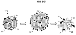
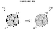
본 공정은 예컨대, 입자 크기, 정렬, 밀도, 에너지곱(BH최대), 잔류 자기(Br), 및 보자력(iHc)의 원하는 조합과 같은, 특정 성능 특징을 가지는 Nd2Fe14B 영구 자석을 생성하는 것을 포함할 수 있다. 예를 들어, 결정립계 공학(GBE) 공정은 개질된 결정립계가 풍부한 상을 포함하는 Nd-Fe-B 영구 자석을 생산하는 것을 포함할 수 있다. GBE 공정은 예컨대, 이전에 소비재에서 사용된 바 없었던 신규한 자성체로부터, 예컨대, 이전에 소비재에서 사용되었던 재활용 자성체로부터, 또는 그 둘 모두로부터 신규한 자석을 생성할 수 있다.This process produces an Nd 2 Fe 14 B permanent magnet having certain performance characteristics, such as, for example, a desired combination of grain size, alignment, density, energy product (BH max), residual magnetization (Br), and coercivity (iHc) Lt; / RTI > For example, the grain boundary engineering (GBE) process may include producing Nd-Fe-B permanent magnets containing modified grain boundary enriched phases. The GBE process can, for example, create new magnets from new magnetic materials that have not previously been used in consumer goods, e.g., from recycled magnetic materials previously used in consumer products, or both.
GBE 공정은 출발 자성체의 결정립계 상을 개질시키면서, 출발 자성체의 원(original) 결정립 상은 유지한다. 예를 들어, 신규 Nd2Fe14B 자석을 생성할 때, GBE 시스템은 출발 물질로부터 최종 자성 생성물 중 90 vol.% 이상의 Nd-Fe-B 2:14:1 상 결정립을 유지한다. GBE 시스템은 Nd가 풍부한 결정립계 상 모두 또는 실질적으로 그들 모두를 첨가제 물질로부터 제조된 신규 결정립계 상으로 대체할 수 있다. 일부 예에서, GBE 시스템은 최종 자성 생성물 중에서 약 90 내지 약 97 vol.%의 출발 결정립을 유지한다. 일부 예에서, GBE 시스템은 약 3 내지 약 12 vol.%의 Nd가 풍부한 결정립계 상을 신규한 결정립계 상으로 대체한다. The GBE process maintains the original crystal phase of the starting magnet, while modifying the grain boundary phase of the starting magnet. For example, when producing a new Nd 2 Fe 14 B magnet, the GBE system retains 90 vol.% Or more of Nd-Fe-B 2: 14: 1 phase grains in the final magnetic product from the starting material. GBE systems can replace all or substantially all of the Nd-enriched grain phases with new grain boundary phases made from additive materials. In some instances, the GBE system maintains a starting grain size of about 90 to about 97 vol.% In the final magnetic product. In some instances, the GBE system replaces the grain boundary phase with a grain boundary phase rich in about 3 to about 12 vol.% Nd.
일반적으로, 본 명세서에 기술된 대상의 한 혁신적 양태는 자성 원소를 용융시켜 용융된 합금을 생성하는 실행 단계, 용융된 합금으로부터 복수 개의 2:14:1 상 결정립을 포함하는 주조 합금 박편을 형성하는 실행 단계, 주조 합금 박편으로부터 2:14:1 상 결정립 중 적어도 일부를 유지시키면서, 주조 합금 박편을 분쇄하여 제1 분말을 생성하는 실행 단계, 제1 분말 중 입자를 압착시키고, 정렬하여 제1 성형체를 생성하는 실행 단계, 제1 성형체를 소결시켜 소결 성형체를 생성하는 실행 단계, 소결 성형체로부터 2:14:1 상 결정립 중 적어도 일부를 유지시키면서, 소결 성형체를 단편화하여 제2 분말을 형성하는 실행 단계, 제2 분말로부터 2:14:1 상 결정립 중 적어도 일부를 유지시키면서, 제2 분말을 a) 희토류 물질 R 및 b) 원소 첨가제 A와 혼합하여 균질한 분말을 제조하는 실행 단계로서, 여기서, 희토류 물질 R은 i) Nd, ii) Pr, 또는 iii) Dy 중 적어도 하나, 적어도 2개, 또는 그들 3개 모두를 포함하고, 원소 첨가제 A는 i) Co, ii) Cu, 또는 iii) Fe 중 적어도 하나, 적어도 2개, 또는 그들 3개 모두를 포함하는 것인 실행 단계, 및 균질한 분말을 소결시키고, 자기화하여 Nd-Fe-B 자성 생성물을 형성하는 실행 단계를 포함하는 방법으로 구현될 수 있다. 본 양태의 다른 실시양태는, 각각이 본 방법의 실행 단계를 수행하도록 구성된 것인, 상응하는 컴퓨터 시스템, 장치, 및 하나 이상의 컴퓨터 저장 장치 상에 기록된 컴퓨터 프로그램을 포함한다. 하나 이상의 컴퓨터의 시스템은 소프트웨어, 펌웨어, 하드웨어, 또는 그의 조합을 시스템에 설치하여 작동시 시스템이 실행 단계를 실행하도록 함으로써 특정 작업 또는 실행 단계를 실행하도록 구성될 수 있다. 하나 이상의 컴퓨터 프로그램은, 데이터 프로세싱 장치에 의해 실행될 때, 장치가 실행 단계를 실행하도록 하는 명령어를 포함함으로써 특정 작업 또는 실행 단계를 실행하도록 설정될 수 있다.Generally, one innovative aspect of the subject matter described herein is an article of manufacture comprising an execution step of melting a magnetic element to produce a molten alloy, forming a cast alloy flake comprising a plurality of 2: 14: 1 phase grains from a molten alloy Comprising the steps of: grinding a cast alloy flake to form a first powder while maintaining at least a portion of 2: 14: 1 phase grains from the cast alloy flake; pressing the particles in the first powder and aligning the first powder; An execution step of sintering the first formed body to produce a sintered formed body; a step of performing fragmentation of the sintered formed body while forming at least a part of 2: 14: 1 phase grains from the sintered compact to form a second powder; The second powder is mixed with a) rare earth materials R and b) elemental additive A while maintaining at least a portion of the 2: 14: 1 phase grains from the second powder to form a homogeneous powder Wherein the rare earth material R comprises at least one, at least two, or all three of i) Nd, ii) Pr, or iii) Dy, wherein the elemental additive A comprises i) Co, ii ) Cu, or iii) at least one or at least two of Fe, or all three of them, and performing and sintering the homogeneous powder and magnetizing to form the Nd-Fe-B magnetic product Step < / RTI > Other embodiments of this aspect include corresponding computer systems, devices, and computer programs recorded on one or more computer storage devices, each configured to perform the steps of the method. A system of one or more computers may be configured to install software, firmware, hardware, or a combination thereof in a system to cause the system to execute an execution step upon operation, thereby executing a particular operation or execution step. The one or more computer programs, when executed by the data processing apparatus, may be configured to execute a particular task or execution step by including instructions that cause the apparatus to execute the execution step.
상기 및 다른 실시양태는 각각 임의적으로 하기 특징들 중 하나 이상의 것을 단독으로 또는 조합하여 포함할 수 있다. 용융된 합금으로부터 복수 개의 2:14:1 상 결정립을 포함하는 주조 합금 박편을 형성하는 실행 단계는 용융된 합금으로부터 각각이 복수 개의 2:14:1 상 결정립을 포함하는 주조 합금 박편을 형성하는 것을 포함할 수 있다. 희토류 물질 R 및 원소 첨가제 A는 함께 Nd11.92Dy42.32Co38.39Cu5.34Fe2.03at.%일 수 있다. These and other embodiments may each optionally include one or more of the following features, alone or in combination. The step of forming a cast alloy flake comprising a plurality of 2: 14: 1 phase grains from a molten alloy comprises forming a cast alloy flake comprising a plurality of 2: 14: 1 phase grains each from a molten alloy . The rare earth material R and the elemental additive A may together be Nd 11.92 Dy 42.32 Co 38.39 Cu 5.34 Fe 2.03 at.%.
일부 실시에서, 소결 성형체를 단편화하는 것은 소결 성형체를 평균 입자 크기가 1 내지 4 ㎛이 되도록 단편화시키는 것을 포함한다. 소결 성형체를 단편화하여 제2 분말을 형성하는 것은 제2 분말로부터, 제2 분말 중 입자 분획 크기가 평균 입자 크기보다 더 큰 입자를 제거하여 Nd-Fe-B 자성 생성물 중 1.98at.% 미만의 산소 농도를 얻는 것을 포함한다. 소결 성형체를 단편화하여 제2 분말을 형성하는 것은 소결 성형체를 단편화하여 평균 입자 크기가 약 1 ㎛ 내지 약 2 mm인 제2 분말을 형성하는 것을 포함할 수 있고, 본 방법은 제2 분말을 제2 분말을 단편화하여 평균 입자 크기가 약 1 내지 약 4 ㎛이 되도록 단편화시키고, 제2 분말을 균질화시키는 것을 추가로 포함한다. 제2 분말을 균질화시키는 것을 포함하고, 평균 입자 크기가 약 1 ㎛ 내지 약 2 mm인 것을 포함하는 제2 분말을 균질화시키고, 제2 분말을 a) 희토류 물질 R 및 b) 원소 첨가제와 혼합하여 균질한 분말을 제조하는 것을 포함할 수 있고, 그리고 제2 분말을 a) 희토류 물질 R 및 b) 원소 첨가제 A와 혼합하여 균질화된 분말을 제조하는 것은 평균 입자 크기가 약 1 내지 약 4 ㎛인 제2 분말을 a) 희토류 물질 R 및 b) 원소 첨가제 A와 혼합하여 균질화된 분말을 제조하는 것을 포함할 수 있다. 제2 분말을 a) 희토류 물질 R 및 b) 원소 첨가제 A와 혼합하여 균질한 분말을 제조하는 것은 평균 입자 크기가 약 1 ㎛ 내지 약 2 mm인 제2 분말을 a) 희토류 물질 R 및 b) 원소 첨가제 A와 혼합하여 균질한 분말을 제조하는 것을 포함할 수 있고, 그리고 제2 분말을 균질화시키는 것은 평균 입자 크기가 약 1 내지 약 4 ㎛인 것을 포함하는 제2 분말을 균질화시키는 것을 포함할 수 있다. In some implementations, fragmenting the sintered compact includes fractionating the sintered compact to an average particle size of 1 to 4 탆. Fragmentation of the sintered compact to form a second powder can be achieved by removing from the second powder particles having a particle fraction size greater than the mean particle size in the second powder to less than 1.98 at.% Oxygen in the Nd-Fe-B magnetic product ≪ / RTI > concentration. Fragmentation of the sintered compact to form a second powder may include fragmenting the sintered compact to form a second powder having an average particle size of about 1 [mu] m to about 2 mm, Fragmenting the powder such that the average particle size is from about 1 to about 4 micrometers, and homogenizing the second powder. Homogenizing a second powder comprising an average particle size of about 1 탆 to about 2 mm and homogenizing the second powder by mixing a) rare earth materials R and b) with an elemental additive to form a homogeneous And mixing the second powder with a) rare earth materials R and b) with the elemental additive A to produce a homogenized powder having a mean particle size of from about 1 to about 4 탆, Mixing the powder with a) rare earth materials R and b) elemental additive A to produce a homogenized powder. Mixing the second powder with a) rare earth materials R and b) element additive A to produce a homogeneous powder comprises the steps of a) mixing a second powder having an average particle size of about 1 μm to about 2 mm with a) rare earth materials R and b) Mixing with the additive A to produce a homogeneous powder, and homogenizing the second powder may include homogenizing a second powder comprising an average particle size of from about 1 to about 4 [mu] m .
일부 실시에서, 소결 성형체를 단편화하여 제2 분말을 형성하는 것과 별개로 희토류 물질 R 및 원소 첨가제 A를 단편화하며, 여기서, 제2 분말을 a) 희토류 물질 R 및 b) 원소 첨가제 A와 혼합하여 균질한 분말을 제조하는 것은 제2 분말을 a) 단편화된 희토류 물질 R 및 b) 단편화된 원소 첨가제 A와 혼합하여 균질한 분말을 제조하는 것을 포함한다. Nd-Fe-B 자성 생성물 중 Co의 원자 비율은 3.098at.% 이하일 수 있다. Nd-Fe-B 자성 생성물 중 Cu의 원자 비율은 0.1849at.% 이하일 수 있다. Nd-Fe-B 자성 생성물 중 Fe 및 Co의 조합된 원자 비율은 약 76.3928 내지 약 83.1267at.%일 수 있다. Nd-Fe-B 자성 생성물 중 Fe 및 Co의 조합된 원자 비율은 77at.% 이하일 수 있다. Nd-Fe-B 자성 생성물 중 Nd, Pr, 및 Dy의 조합된 원자 비율은 소결 성형체 중 Nd, Pr, 및 Dy의 조합된 원자 비율보다 크거나, 또는 그와 같을 수 있다. Nd-Fe-B 자성 생성물 중 Nd, Dy, 및 Pr의 조합된 원자 비율은 18at.% 이하일 수 있다. In some implementations, the sintered compact is fragmented to fractionate rare earth material R and elemental additive A separately from forming a second powder, wherein the second powder is mixed with a) rare earth materials R and b) The preparation of one powder comprises mixing a second powder with a) a fragmented rare earth material R and b) a fragmented element additive A to produce a homogeneous powder. The atomic ratio of Co in the Nd-Fe-B magnetic product may be 3.098 at.% Or less. The atomic ratio of Cu in the Nd-Fe-B magnetic product can be 0.1849 at.% Or less. The combined atomic ratio of Fe and Co in the Nd-Fe-B magnetic product may be from about 76.3928 to about 83.1267 at.%. The combined atomic ratio of Fe and Co in the Nd-Fe-B magnetic product may be less than 77 at.%. The combined atomic ratio of Nd, Pr, and Dy in the Nd-Fe-B magnetic product may be greater than or equal to the combined atomic ratio of Nd, Pr, and Dy in the sintered compact. The combined atomic ratio of Nd, Dy, and Pr in the Nd-Fe-B magnetic product may be less than 18 at.%.
일부 실시에서, 제2 분말을 a) 희토류 물질 R 및 b) 원소 첨가제 A와 혼합하여 균질한 분말을 제조하는 것은 제2 분말 내에 희토류 물질 R 및 원소 첨가제 A를 균질하게 분포시키는 것을 포함하고, 균질한 분말을 소결시키고, 자기화하여 Nd-Fe-B 자성 생성물을 형성하는 것은 대체로 Nd-Fe-B 자성 생성물 내에서 2:14:1 상 결정립을 감싸도록 증가되는 희토류 물질 R의 농도 및 원소 첨가제 A의 농도를 갖는 Nd-Fe-B 자성 생성물을 형성하는 것을 포함한다. 본 방법은 소결 성형체로부터 제2 분말에 포함된 구형의 Nd가 풍부한 결정립계 상을 희토류 물질 R 및 원소 첨가제 A를 포함하는 신규한 결정립계 상으로 대체하는 것을 포함할 수 있다. In some implementations, mixing a second powder with a rare earth material R and b) element additive A to produce a homogeneous powder comprises homogenously distributing the rare earth material R and elemental additive A in a second powder, Sintering and magnetizing a powder to form an Nd-Fe-B magnetic product results in an increase in the concentration of the rare earth material R, which is increased to enclose the 2: 14: 1 phase grains in the Nd-Fe-B magnetic product, A-Nd-Fe-B < / RTI > The method may comprise replacing the spherical Nd-enriched grain boundary phase contained in the second powder from the sintered formed body with a new grain boundary phase comprising rare earth material R and elemental additive A.
일부 실시에서, Nd-Fe-B 자성 생성물은 범위가 [7.3635, 11.1038](at.%)(하한 및 상한 포함)인 양의 Nd, 범위가 [76.3928, 80.0287](at.%)(하한 및 상한 포함)인 양의 Fe, 및 범위가 [5.7493, 6.4244](at.%)(하한 및 상한 포함)인 양의 B를 포함한다. Nd-Fe-B 자성 생성물은 범위가 [0.09, 4.0](at.%)(하한 및 상한 포함)인 양의 O, 및 범위가 [0.01, 1.0](at.%)(하한 및 상한 포함)인 양의 C를 포함할 수 있다. Nd-Fe-B 자성 생성물은 범위가 [0.199, 4.0535](at.%)(하한 및 상한 포함)인 양의 Dy를 포함할 수 있다. Nd-Fe-B 자성 생성물은 범위가 [1.445, 3.6323](at.%)(하한 및 상한 포함)인 양의 Pr을 포함할 수 있다. Nd-Fe-B 자성 생성물은 범위가 [0, 3.098](at.%)(하한 및 상한 포함)인 양의 Co를 포함할 수 있다. Nd-Fe-B 자성 생성물은 범위가 [0.0508, 0.1849](at.%)(하한 및 상한 포함)인 양의 Cu를 포함할 수 있다. Nd-Fe-B 자성 생성물 중 희토류 물질 R의 총량은 [12.66, 15.03](at.%)(하한 및 상한 포함) 범위일 수 있다. In some implementations, the Nd-Fe-B magnetic product has a positive Nd in the range [7.3635, 11.1038] (at.%) (Including lower and upper limits), a range of [76.3928, 80.0287] (Including the upper and lower limits), and an amount B of the range [5.7493, 6.4244] (at.%) (Including lower and upper limits). The Nd-Fe-B magnetic product has a positive O and a range of [0.01, 1.0] (at.%) (Including lower and upper limits) in the range [0.09, 4.0] (at.%) Lt; RTI ID = 0.0 > C. ≪ / RTI > The Nd-Fe-B magnetic product may contain an amount of Dy in the range [0.199, 4.0535] (at.%) (Including lower and upper limits). The Nd-Fe-B magnetic product may contain a positive Pr in the range [1.445, 3.6323] (at.%) (Including lower and upper limits). The Nd-Fe-B magnetic product may contain an amount of Co in the range [0, 3.098] (at.%) (Including lower and upper limits). The Nd-Fe-B magnetic product may contain an amount of Cu in the range [0.0508, 0.1849] (at.%) (Including lower and upper limits). The total amount of rare earth material R in the Nd-Fe-B magnetic product may range from [12.66, 15.03] (at.%) (Including lower and upper limits).
일부 실시에서, 희토류 물질 R은 i) 범위가 [6.1717, 11.8917](at.%)(하한 및 상한 포함)인 양의 Nd, ii) 범위가 [1.5495, 4.821](at.%)(하한 및 상한 포함)인 양의 Pr, 또는 iii) 범위가 [0.2132, 5.3753](at.%)(하한 및 상한 포함)인 양의 Dy 중 적어도 하나를 포함하고, 원소 첨가제 A는 i) 범위가 [0, 4.0948](at.%)(하한 및 상한 포함)인 양의 Co, ii) 범위가 [0.0545, 0.2445](at.%)(하한 및 상한 포함)인 양의 Cu, 또는 iii) 범위가 [81.1749, 85.867](at.%)(하한 및 상한 포함)인 양의 Fe 중 적어도 하나를 포함한다. 상기 범위는 비사용 자석 물질인지 또는 폐 자석 물질인지 여부와 상관 없이, 출발 자성체가 아닌, 오직 희토류 물질 R 및 원소 첨가제 A와 관련된 것이다. In some implementations, the rare earth material R is selected from the group consisting of: i) Nd of the amount in the range [6.1717, 11.8917] (at.%) (Inclusive of the lower and upper limits), ii) range of [1.5495, 4.821] (I. E., The upper limit is inclusive), or iii) the amount of Dy in the range of [0.2132, 5.3753] (inclusive) ), (Ii) a positive Cu with a range of [0.0545, 0.2445] (at.%) (Inclusive of the lower and upper limits), or iii) a range of [ 81.1749, 85.867] (at.%) (Including lower and upper limits). The range is related only to rare earth material R and element additive A, not to the starting magnet, irrespective of whether it is an unused magnetic substance or a discarded magnet material.
일부 실시에서, 균질한 분말을 소결시키고, 자기화하여 Nd-Fe-B 자성 생성물을 형성하는 것은 균질한 분말을 소결시키고, 자기화하여 잔류 자기 및 보자력이 적어도 소결 성형체와 동일한 Nd-Fe-B 자성 생성물을 형성하는 것을 포함한다. Nd-Fe-B 자성 생성물의 보자력은 소결 성형체의 보자력보다 약 0 내지 약 20% 더 클 수 있다. 균질한 분말을 소결시키고, 자기화하여 Nd-Fe-B 자성 생성물을 형성하는 것은 균질한 분말을 소결시키고, 자기화하여, 최종 잔류 자기가 소결 성형체의 또 다른 잔류 자기의 약 97%이고, 최종 보자력이 소결 성형체의 또 다른 보자력보다 30% 이상 더 큰 것인, 최종 잔류 자기 및 최종 보자력을 가지는 Nd-Fe-B 자성 생성물을 형성하는 것을 포함할 수 있다. 균질한 분말을 소결시키고, 자기화하여 Nd-Fe-B 자성 생성물을 형성하는 것은 균질한 분말을 소결시키고, 자기화하여, 최종 잔류 자기가 소결 성형체의 또 다른 잔류 자기의 약 95%이고, 최종 보자력이 소결 성형체의 또 다른 보자력보다 80% 이상 더 큰 것인, 최종 잔류 자기 및 최종 보자력을 가지는 Nd-Fe-B 자성 생성물을 형성하는 것을 포함할 수 있다. 균질한 분말을 소결시키고, 자기화하여 Nd-Fe-B 자성 생성물을 형성하는 것은 균질한 분말을 소결시키고, 자기화하여, 최종 잔류 자기가 소결 성형체의 또 다른 잔류 자기보다 약 5% 더 크고, 최종 보자력이 소결 성형체의 또 다른 보자력과 적어도 동일한 것인, 최종 잔류 자기 및 최종 보자력을 가지는 Nd-Fe-B 자성 생성물을 형성하는 것을 포함할 수 있다.In some implementations, sintering a homogeneous powder and magnetizing it to form an Nd-Fe-B magnetic product is performed by sintering a homogeneous powder and magnetizing it so that the residual magnetic and coercive forces are at least equal to the Nd-Fe-B To form a magnetic product. The coercive force of the Nd-Fe-B magnetic product may be about 0 to about 20% greater than the coercive force of the sintered compact. Sintering the homogeneous powder and magnetizing it to form the Nd-Fe-B magnetic product sintered and magnetized the homogeneous powder to obtain a final residual magnetism of about 97% of another residual magnetism of the sintered compact, Forming a final residual magnetic and Nd-Fe-B magnetic product having a final coercive force, wherein the coercive force is at least 30% greater than another coercive force of the sintered compact. Sintering the homogeneous powder and magnetizing it to form the Nd-Fe-B magnetic product sinter and homogenize the homogeneous powder resulting in about 95% of the final residual magnetism of the other residual magnetism of the sintered compact, Forming a final residual magnetic and Nd-Fe-B magnetic product having a final coercive force, wherein the coercive force is at least 80% greater than another coercive force of the sintered compact. Sintering the homogeneous powder and magnetizing it to form the Nd-Fe-B magnetic product sinter and homogenize the homogeneous powder so that the final residual magnetism is about 5% larger than the other residual magnetism of the sintered compact, Forming a final residual magnetic and Nd-Fe-B magnetic product having a final coercive force, wherein the final coercive force is at least the same as another coercive force of the sintered formed body.
일반적으로, 본 명세서에 기술된 대상의 한 혁신적 양태는 Nd1 - 20Dy1 - 60Co1 -60Cu0.1_20Fe0.5-90at.%를 포함하는 화합물로 구현될 수 있다. 화합물은 Nd7 - 14Dy30 - 50Co28 -45Cu1-10Fe1-10at.%일 수 있다. 화합물은 Nd8 .5-12. 5Dy35 - 45Co32 - 41Cu3 - 6.5Fe1 .5- 5at.%일 수 있다. 화합물은 Nd11 . 92Dy42 . 32Co38 . 39Cu5 . 34Fe2 . 03at.%일 수 있다. 화합물은 0.12at.% 미만의 산소, 0.0058at.% 미만의 탄소, 또는 이 둘 모두를 포함할 수 있다. 일부 예에서, 화합물은 0.00009 내지 0.18at.%의 산소, 또는 0.028 내지 0.1at.%의 산소를 포함할 수 있다. 일부 예에서, 화합물은 0.0001 내지 0.09at.%의 탄소, 또는 0.0058 내지 0.009at.%의 탄소를 포함할 수 있다. In general, one innovative aspect of the subject described herein Nd 1 - may also be implemented as a compound comprising a 60 Co 1 -60 Cu 0.1_20 Fe 0.5-90 at% - 20
일부 실시에서, 화합물은 본질적으로 언급되는 화학식으로 이루어질 수 있다. 예를 들어, 화합물은 본질적으로 Nd1 - 20Dy1 - 60Co1 - 60Cu0 .1- 20Fe0 .5- 90at.%, Nd7 - 14Dy30 -50Co28-45Cu1-10Fe1-10at.%, Nd8 .5-12. 5Dy35 - 45Co32 - 41Cu3 - 6.5Fe1 .5- 5at.%, 또는 Nd11.92Dy42.32Co38.39Cu5.34Fe2.03at.%로 이루어질 수 있다. 화합물은 0.12at.% 미만의 산소, 0.0058at.% 미만의 탄소, 또는 이 둘 모두를 포함할 수 있다. 일부 예에서, 화합물은 0.00009 내지 0.18at.%의 산소, 또는 0.028 내지 0.1at.%의 산소를 포함할 수 있다. 일부 예에서, 화합물은 0.0001 내지 0.09at.%의 탄소, 또는 0.0058 내지 0.009at.%의 탄소를 포함할 수 있다.In some implementations, the compound may consist essentially of the recited formula. For example, the compounds are essentially Nd 1 - 20 Dy 1 - 60
일반적으로, 본 명세서에 기술된 대상의 한 혁신적 양태는 i) 범위가 [6.1717 이상, 11.8917](at.%)(하한 및 상한 포함)인 양의 Nd, ii) Pr 범위가 [1.5495, 4.821](at.%)(하한 및 상한 포함)인 양의 Pr, 또는 iii) 범위가 [0.2132, 5.3753](at.%)(하한 및 상한 포함)인 양의 Dy, 및 범위가 [0, 4.0948](at.%)(하한 및 상한 포함)인 양의 Co, 범위가 [0.0545, 0.2445](at.%)(하한 및 상한 포함)인 양의 Cu, 및 범위가 [81.1749, 85.867](at.%)(하한 및 상한 포함)인 양의 Fe 중 적어도 하나를 포함하는 화합물로 구현될 수 있다. 화합물은 범위가 [13.236, 16.407]at.%(하한 및 상한 포함)인 Nd, Pr, 및 Dy의 조합을 포함할 수 있다. 화합물은 적어도 Nd 및 Dy, 둘 모두를 포함할 수 있다. 화합물은 적어도 Nd 및 Pr, 둘 모두를 포함할 수 있다. 화합물은 Nd를 포함할 수 있다. 화합물은 0.00009 내지 0.18at.%의 산소(O)를 포함할 수 있다. 화합물은 0.028 내지 0.1at.%의 산소(O)를 포함할 수 있다. 화합물은 0.0001 내지 0.09at.%의 탄소(C)를 포함할 수 있다. 화합물은 0.0058 내지 0.009at.%의 탄소(C)를 포함할 수 있다.Generally, one of the innovative aspects of the subject matter described herein is i) a positive Nd in the range of [6.1717 or more, 11.8917] (at.%) (Including lower and upper limits), ii) a Pr range of [1.5495, 4.821] (i. e.%) (at.%) (inclusive of the lower and upper limits), or iii) Dy of the quantity in the range [0.2132, 5.3753] (at.%) (including lower and upper limits), a positive Co at a range of [0.0545, 0.2445] (at.%) (including lower and upper limits), and a range of [81.1749, 85.867] (at. %) (Inclusive of the lower and upper limits). The compound may comprise a combination of Nd, Pr, and Dy with a range [13.236, 16.407] at.% (Including lower and upper limits). The compound may comprise at least Nd and Dy, both. The compound may comprise at least Nd and Pr, both. The compound may include Nd. The compound may comprise 0.00009 to 0.18 at.% Oxygen (O). The compound may comprise 0.028 to 0.1 at.% Oxygen (O). The compound may contain from 0.0001 to 0.09 at.% Carbon (C). The compound may comprise from 0.0058 to 0.009 at.% Carbon (C).
일반적으로, 본 명세서에 기술된 대상의 한 혁신적 양태는 Cu, Co, 및 Fe, 및 Nd, Pr, Dy, 또는 Tb 중 하나 이상의 것을 용융시켜 용융된 합금을 생성하는 실행 단계, 및 용융된 합금을 냉각시켜 주조 합금 박편을 생성하는 실행 단계를 포함하는 방법으로 구현될 수 있다. 본 양태의 다른 실시양태는, 각각이 본 방법의 실행 단계를 실행하도록 구성된 것인, 상응하는 컴퓨터 시스템, 장치, 및 하나 이상의 컴퓨터 저장 장치 상에 기록된 컴퓨터 프로그램을 포함한다. 하나 이상의 컴퓨터의 시스템은 소프트웨어, 펌웨어, 하드웨어, 또는 그의 조합을 시스템에 설치하여 작동시 시스템이 실행 단계를 실행하도록 함으로써 특정 작업 또는 실행 단계를 실행하도록 구성될 수 있다. 하나 이상의 컴퓨터 프로그램은, 데이터 프로세싱 장치에 의해 실행될 때, 장치가 실행 단계를 실행하도록 하는 명령어를 포함함으로써 특정 작업 또는 실행 단계를 실행하도록 구성될 수 있다. In general, one innovative aspect of the subject matter described herein is a method of making a molten alloy by melting at least one of Cu, Co, and Fe and Nd, Pr, Dy, or Tb to produce a molten alloy, And cooling to produce a cast alloy flake. Other embodiments of this aspect include corresponding computer systems, devices, and computer programs recorded on one or more computer storage devices, each configured to execute the steps of the method. A system of one or more computers may be configured to install software, firmware, hardware, or a combination thereof in a system to cause the system to execute an execution step upon operation, thereby executing a particular operation or execution step. The one or more computer programs, when executed by the data processing apparatus, may be configured to execute a particular task or execution step by including instructions that cause the apparatus to execute the execution step.
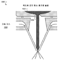
일반적으로, 본 명세서에 기술된 대상의 한 혁신적 양태는 Cu, Co, 및 Fe, 및 Nd, Pr, Dy, 또는 Tb 중 하나 이상의 것을 용융시켜 용융된 합금을 생성하는 실행 단계, 및 용융된 합금을 분사 분무 장치를 사용하여 고속 가스 분사로 단편화시켜 Cu, Co, Fe, 및 Nd, Pr, Dy, 또는 Tb 중 하나 이상의 것으로부터 형성된 화합물 액적을 생성하는 실행 단계를 포함하는 방법으로 구현될 수 있다. 본 양태의 다른 실시양태는, 각각이 본 방법의 실행 단계를 실행하도록 구성된 것인, 상응하는 컴퓨터 시스템, 장치, 및 하나 이상의 컴퓨터 저장 장치 상에 기록된 컴퓨터 프로그램을 포함한다. 하나 이상의 컴퓨터의 시스템은 소프트웨어, 펌웨어, 하드웨어, 또는 그의 조합을 시스템에 설치하여 작동시 시스템이 실행 단계를 실행하도록 함으로써 특정 작업 또는 실행 단계를 실행하도록 구성될 수 있다. 하나 이상의 컴퓨터 프로그램은, 데이터 프로세싱 장치에 의해 실행될 때, 장치가 실행 단계를 실행하도록 하는 명령어를 포함함으로써 특정 작업 또는 실행 단계를 실행하도록 구성될 수 있다. In general, one innovative aspect of the subject matter described herein is a method of making a molten alloy by melting at least one of Cu, Co, and Fe and Nd, Pr, Dy, or Tb to produce a molten alloy, And performing an action step of generating a compound droplet formed from at least one of Cu, Co, Fe, and Nd, Pr, Dy, or Tb by fragmenting by high-speed gas injection using a spray atomizing apparatus. Other embodiments of this aspect include corresponding computer systems, devices, and computer programs recorded on one or more computer storage devices, each configured to execute the steps of the method. A system of one or more computers may be configured to install software, firmware, hardware, or a combination thereof in a system to cause the system to execute an execution step upon operation, thereby executing a particular operation or execution step. The one or more computer programs, when executed by the data processing apparatus, may be configured to execute a particular task or execution step by including instructions that cause the apparatus to execute the execution step.
상기 및 다른 실시양태는 각각 임의적으로 하기 특징들 중 하나 이상의 것을 단독으로 또는 조합하여 포함할 수 있다. Cu, Co, 및 Fe, 및 Nd, Pr, Dy, 또는 Tb 중 하나 이상의 것을 용융시켜 용융된 합금을 생성하는 것은 Cu, Co, 및 Fe, 및 Nd, Pr, Dy, 또는 Tb 중 하나 이상의 것을 유도 용융시켜 용융된 합금을 생성하는 것을 포함할 수 있다. Cu, Co, 및 Fe, 및 Nd, Pr, Dy, 또는 Tb 중 하나 이상의 것을 용융시켜 용융된 합금을 생성하는 것은 Cu, Co, 및 Fe, 및 Nd, Pr, Dy, 또는 Tb 중 하나 이상의 것을 아크 용융시켜 용융된 합금을 생성하는 것을 포함할 수 있다. 용융된 합금을 냉각시켜 주조 합금 박편을 생성하는 것은 용융된 합금을 냉각시켜 잉곳을 생성하고, 잉곳을 재용융시켜 제2 용융된 합금을 제조하고, 제2 용융된 합금을 냉각시켜 주조 합금 박편을 생성하는 것을 포함할 수 있다. These and other embodiments may each optionally include one or more of the following features, alone or in combination. The melting of at least one of Cu, Co, and Fe and Nd, Pr, Dy, or Tb to produce a molten alloy can result in Cu, Co, and Fe and at least one of Nd, Pr, Dy, And melting to produce a molten alloy. The melting of at least one of Cu, Co, and Fe and Nd, Pr, Dy, or Tb to produce a molten alloy may include at least one of Cu, Co, and Fe and at least one of Nd, Pr, Dy, And melting to produce a molten alloy. Cooling the molten alloy to produce a cast alloy flake can be accomplished by cooling the molten alloy to produce an ingot, re-melting the ingot to produce a second molten alloy, cooling the second molten alloy to produce a cast alloy flake Lt; / RTI >
일부 실시에서, 본 방법은 용융된 합금을 아르곤 퍼징을 사용하여 교반함으로써 Cu, Co, 및 Fe, 및 Nd, Pr, Dy, 또는 Tb 중 하나 이상의 것을 용융된 합금 전반에 걸쳐 균질하게 분포시키는 것을 포함할 수 있다. Cu, Co, 및 Fe, 및 Nd, Pr, Dy, 또는 Tb 중 하나 이상의 것을 용융시켜 용융된 합금을 생성하는 것은 불활성 분위기에서 Cu, Co, 및 Fe, 및 Nd, Pr, Dy, 또는 Tb 중 하나 이상의 것을 용융시켜 용융된 합금을 생성하는 것을 포함할 수 있다. 불활성 분위기에서 Cu, Co, 및 Fe, 및 Nd, Pr, Dy, 또는 Tb 중 하나 이상의 것을 용융시켜 용융된 합금을 생성하는 것은 환원제를 포함하는 불활성 분위기에서 Cu, Co, 및 Fe, 및 Nd, Pr, Dy, 또는 Tb 중 하나 이상의 것을 용융시키는 것을 포함할 수 있다. Cu, Co, 및 Fe, 및 Nd, Pr, Dy, 또는 Tb 중 하나 이상의 것을 용융시켜 용융된 합금을 생성하는 것은 1.5 내지 1.8 bar인 압력에서 Cu, Co, 및 Fe, 및 Nd, Pr, Dy, 또는 Tb 중 하나 이상의 것을 용융시켜 용융된 합금을 생성하는 것을 포함할 수 있다.In some implementations, the method includes homogenously distributing Cu, Co, and Fe, and at least one of Nd, Pr, Dy, or Tb throughout the molten alloy by agitating the molten alloy using argon purging can do. The melting of at least one of Cu, Co, and Fe and Nd, Pr, Dy, or Tb to produce a molten alloy can be accomplished by combining Cu, Co, and Fe in an inert atmosphere and one of Nd, Pr, Dy, Or more to produce a molten alloy. The melting of at least one of Cu, Co, and Fe, and Nd, Pr, Dy, or Tb in an inert atmosphere to produce a molten alloy is accomplished by mixing Cu, Co, and Fe, and Nd, Pr , Dy, or Tb. The method for producing a molten alloy by melting one or more of Cu, Co, and Fe and Nd, Pr, Dy, or Tb is conducted by reacting Cu, Co, and Fe, and at least one of Nd, Pr, Dy, Or < RTI ID = 0.0 > Tb < / RTI > to produce a molten alloy.
일부 실시에서, Cu, Co, 및 Fe, 및 Nd, Pr, Dy, 또는 Tb 중 하나 이상의 것을 용융시켜 용융된 합금을 생성하는 것은 진공 유도를 사용하여 Cu, Co, 및 Fe, 및 Nd, Pr, Dy, 또는 Tb 중 하나 이상의 것을 용융시켜 용융된 합금을 생성하는 것을 포함한다. Cu, Co, 및 Fe, 및 Nd, Pr, Dy, 또는 Tb 중 하나 이상의 것을 용융시켜 용융된 합금을 생성하는 것은 1,450℃에서 Cu, Co, 및 Fe, 및 Nd, Pr, Dy, 또는 Tb 중 하나 이상의 것을 용융시켜 용융된 합금을 생성하는 것을 포함한다. Cu, Co, 및 Fe, 및 Nd, Pr, Dy, 또는 Tb 중 하나 이상의 것을 용융시켜 용융된 합금을 생성하는 것은 알루미나 도가니에서 Cu, Co, 및 Fe, 및 Nd, Pr, Dy, 또는 Tb 중 하나 이상의 것을 용융시켜 용융된 합금을 생성하는 것을 포함할 수 있다. Cu, Co, 및 Fe, 및 Nd, Pr, Dy, 또는 Tb 중 하나 이상의 것을 용융시켜 용융된 합금을 생성하는 것은 지르코늄 도가니에서 Cu, Co, 및 Fe, 및 Nd, Pr, Dy, 또는 Tb 중 하나 이상의 것을 용융시켜 용융된 합금을 생성하는 것을 포함할 수 있다. Cu, Co, 및 Fe, 및 Nd, Pr, Dy, 또는 Tb 중 하나 이상의 것을 용융시켜 용융된 합금을 생성하는 것은 구리 도가니에서 Cu, Co, 및 Fe, 및 Nd, Pr, Dy, 또는 Tb 중 하나 이상의 것을 용융시켜 용융된 합금을 생성하는 것을 포함할 수 있다. In some implementations, melting Cu, Co, and Fe, and at least one of Nd, Pr, Dy, or Tb to produce a molten alloy can be achieved using Cu, Co, and Fe, and Nd, Pr, Dy, or Tb to produce a molten alloy. Melting of at least one of Cu, Co, and Fe and Nd, Pr, Dy, or Tb to produce a molten alloy can be accomplished by combining Cu, Co, and Fe, and one of Nd, Pr, Dy, Or more to produce a molten alloy. The melting of at least one of Cu, Co, and Fe and Nd, Pr, Dy, or Tb to produce a molten alloy is accomplished by combining Cu, Co, and Fe in the alumina crucible and one of Nd, Pr, Dy, Or more to produce a molten alloy. The melting of at least one of Cu, Co, and Fe and Nd, Pr, Dy, or Tb to produce a molten alloy is accomplished by combining Cu, Co, and Fe in the zirconium crucible and one of Nd, Pr, Dy, Or more to produce a molten alloy. Melting the at least one of Cu, Co, and Fe and Nd, Pr, Dy, or Tb to produce a molten alloy can be achieved by combining Cu, Co, and Fe in the copper crucible and one of Nd, Pr, Dy, Or more to produce a molten alloy.
일부 실시에서, Cu, Co, 및 Fe, 및 Nd, Pr, Dy, 또는 Tb 중 하나 이상의 것을 용융시켜 용융된 합금을 생성하는 것은 고밀도 도가니에서 Cu, Co, 및 Fe, 및 Nd, Pr, Dy, 또는 Tb 중 하나 이상의 것을 용융시켜 용융된 합금을 생성하는 것을 포함할 수 있다. Cu, Co, 및 Fe, 및 Nd, Pr, Dy, 또는 Tb 중 하나 이상의 것을 용융시켜 용융된 합금을 생성하는 것은 고순도 도가니에서 Cu, Co, 및 Fe, 및 Nd, Pr, Dy, 또는 Tb 중 하나 이상의 것을 용융시켜 용융된 합금을 생성하는 것을 포함할 수 있다. In some implementations, melting of at least one of Cu, Co, and Fe and Nd, Pr, Dy, or Tb to produce a molten alloy can be accomplished by combining Cu, Co, and Fe in a high density crucible, Or < RTI ID = 0.0 > Tb < / RTI > to produce a molten alloy. Melting the at least one of Cu, Co, and Fe and Nd, Pr, Dy, or Tb to produce a molten alloy can be achieved by combining Cu, Co, and Fe in a high purity crucible and one of Nd, Pr, Dy, Or more to produce a molten alloy.
일부 실시에서, Cu, Co, 및 Fe, 및 Nd, Pr, Dy, 또는 Tb 중 하나 이상의 것을 용융시켜 용융된 합금을 생성하는 것은 Nd를 용융시키는 것을 포함한다. Cu, Co, 및 Fe, 및 Nd, Pr, Dy, 또는 Tb 중 하나 이상의 것을 용융시켜 용융된 합금을 생성하는 것은 Dy를 용융시키는 것을 포함할 수 있다. Cu, Co, 및 Fe, 및 Nd, Pr, Dy, 또는 Tb 중 하나 이상의 것을 용융시켜 용융된 합금을 생성하는 것은 Nd 및 Dy를 용융시키는 것을 포함할 수 있다. Cu, Co, 및 Fe, 및 Nd, Pr, Dy, 또는 Tb 중 하나 이상의 것을 용융시켜 용융된 합금을 생성하는 것은 Pr을 용융시키는 것을 포함할 수 있다. Cu, Co, 및 Fe, 및 Nd, Pr, Dy, 또는 Tb 중 하나 이상의 것을 용융시켜 용융된 합금을 생성하는 것은 Tb를 용융시키는 것을 포함할 수 있다. Cu, Co, 및 Fe, 및 Nd, Pr, Dy, 또는 Tb 중 하나 이상의 것을 용융시켜 용융된 합금을 생성하는 것은 Pr 및 Tb를 용융시키는 것을 포함할 수 있다. In some implementations, melting one or more of Cu, Co, and Fe, and Nd, Pr, Dy, or Tb to produce a molten alloy includes melting Nd. Melting one or more of Cu, Co, and Fe and Nd, Pr, Dy, or Tb to produce a molten alloy can include melting Dy. Melting one or more of Cu, Co, and Fe, and Nd, Pr, Dy, or Tb to produce a molten alloy can include melting Nd and Dy. Melting one or more of Cu, Co, and Fe, and Nd, Pr, Dy, or Tb to produce a molten alloy can include melting Pr. Melting one or more of Cu, Co, and Fe, and Nd, Pr, Dy, or Tb to produce a molten alloy can include melting the Tb. Melting one or more of Cu, Co, and Fe and Nd, Pr, Dy, or Tb to produce a molten alloy can include melting Pr and Tb.
일부 실시에서, Cu, Co, 및 Fe, 및 Nd, Pr, Dy, 또는 Tb 중 하나 이상의 것을 용융시켜 용융된 합금을 생성하는 것은 도가니에서 Cu, Co, 및 Fe, 및 Nd, Pr, Dy, 또는 Tb 중 하나 이상의 것을 용융시켜 용융된 합금을 생성하는 것을 포함하고, 용융된 합금을 냉각시켜 주조 합금 박편을 생성하는 것은 용융된 합금을 도가니에서 냉각시키는 것을 포함한다. 용융된 합금을 냉각시켜 주조 합금 박편을 생성하는 것은 용융된 합금을 수냉각 휠에 주입하여 주조 합금 박편을 생성하는 것을 생성하는 것을 포함할 수 있다. 용융된 합금을 수냉각 휠에 주입하여 주조 합금 박편을 생성하는 것은 용융된 합금을 구리 수냉각 휠에 주입하여 주조 합금 박편을 생성하는 것을 포함할 수 있다. In some implementations, melting Cu, Co, and Fe, and at least one of Nd, Pr, Dy, or Tb to produce a molten alloy can be accomplished using Cu, Co, and Fe, and Nd, Pr, Tb to produce a molten alloy, wherein cooling the molten alloy to produce a cast alloy flake comprises cooling the molten alloy in the crucible. Cooling the molten alloy to produce a cast alloy flake can include injecting the molten alloy into a water-cooled wheel to produce a cast alloy flake. Injecting the molten alloy into a water cooled wheel to produce a cast alloy flake can include injecting the molten alloy into a copper water cooling wheel to produce a cast alloy flake.
일부 실시에서, 용융된 합금을 냉각시켜 주조 합금 박편을 생성하는 것은 105 켈빈/초인 비율로 용융된 합금을 냉각시키는 것을 포함한다. 용융된 합금을 냉각시켜 주조 합금 박편을 생성하는 것은 10 내지 100 켈빈/초인 비율로 용융된 합금을 냉각시키는 것을 포함할 수 있다. 용융된 합금을 냉각시켜 주조 합금 박편을 생성하는 것은 10-1 bar 초과의 압력으로 진공에서 용융된 합금을 냉각시키는 것을 포함할 수 있다. In some implementations, cooling the molten alloy to produce a cast alloy flake includes cooling the molten alloy at a rate of 10 5 Kelvin / sec. Cooling the molten alloy to produce cast alloy flakes can include cooling the molten alloy at a rate of 10 to 100 Kelvin / sec. Cooling the molten alloy to produce cast alloy flakes can include cooling the molten alloy in vacuum at a pressure of greater than 10 <" 1 > bar.
일부 실시에서, 용융된 합금을 분사 분무 장치를 사용하여 고속 가스 분사로 단편화시켜 Cu, Co, Fe, 및 Nd, Pr, Dy, 또는 Tb 중 하나 이상의 것으로부터 형성된 화합물 액적을 생성하는 것은 화합물 액적을 생성하였을 때, 용융된 합금으로부터 약 2wt.% 미만의 Cu, Co, Fe, 및 Nd, Pr, Dy, 또는 Tb 중 하나 이상의 것을 제거하는 것을 포함한다. 용융된 합금을 분사 분무 장치를 사용하여 고속 가스 분사로 단편화시켜 Cu, Co, Fe, 및 Nd, Pr, Dy, 또는 Tb 중 하나 이상의 것으로부터 형성된 화합물 액적을 생성하는 것은 산소 농도가 최대 0.04wt.%이거나, 탄소 농도가 0.0058at.% 미만이거나, 또는 그 둘 모두인 화합물 액적을 생성하는 것을 포함할 수 있다. 일부 예에서, 화합물 액적은 0.00009 내지 0.18at.%의 산소, 또는 0.028 내지 0.1at.%의 산소를 포함할 수 있다. 일부 예에서, 화합물 액적은 0.0001 내지 0.09at.%의 탄소, 또는 0.0058 내지 0.009at.%의 탄소를 포함할 수 있다. 용융된 합금을 분사 분무 장치를 사용하여 고속 가스 분사로 단편화시켜 Cu, Co, Fe, 및 Nd, Pr, Dy, 또는 Tb 중 하나 이상의 것으로부터 형성된 화합물 액적을 생성하는 것은 용융된 합금을 불활성 가스 분사를 이용하여 단편화시키는 것을 포함할 수 있다. 용융된 합금을 분사 분무 장치를 사용하여 고속 가스 분사로 단편화시켜 Cu, Co, Fe, 및 Nd, Pr, Dy, 또는 Tb 중 하나 이상의 것으로부터 형성된 화합물 액적을 생성하는 것은 용융된 합금을 500 m/s 속도로 가스 분사를 이용하여 단편화시키는 것을 포함할 수 있다. In some implementations, the production of compound droplets formed from at least one of Cu, Co, Fe, and Nd, Pr, Dy, or Tb by fragmenting the molten alloy with high velocity gas injection using a spray atomizer, Less than about 2 wt.% Of Cu, Co, Fe, and one or more of Nd, Pr, Dy, or Tb from the molten alloy when formed. The molten alloy is fragmented by high velocity gas injection using an atomizing atomizer to produce compound droplets formed from at least one of Cu, Co, Fe, and Nd, Pr, Dy, or Tb with oxygen concentrations of up to 0.04 wt. %, Or a carbon concentration of less than 0.0058 at.%, Or both. In some instances, the compound droplet may include 0.00009 to 0.18 at.% Oxygen, or 0.028 to 0.1 at.% Oxygen. In some examples, the compound droplet may comprise from 0.0001 to 0.09 at.% Carbon, or from 0.0058 to 0.009 at.% Carbon. The molten alloy is fragmented by high velocity gas injection using a spray atomizer to produce compound droplets formed from at least one of Cu, Co, Fe, and Nd, Pr, Dy, or Tb, , ≪ / RTI > The molten alloy is fragmented by high velocity gas injection using a spray atomizer to produce compound droplets formed from at least one of Cu, Co, Fe, and Nd, Pr, Dy, or Tb, s < / RTI > speed using gas injection.
일부 실시에서, 용융된 합금을 분사 분무 장치를 사용하여 고속 가스 분사로 단편화시켜 Cu, Co, Fe, 및 Nd, Pr, Dy, 또는 Tb 중 하나 이상의 것으로부터 형성된 화합물 액적을 생성하는 것은 용융된 합금을 0.18 내지 0.58 MPa의 압력으로 가스 분사를 이용하여 단편화시키는 것을 포함한다. 용융된 합금을 분사 분무 장치를 사용하여 고속 가스 분사로 단편화시켜 Cu, Co, Fe, 및 Nd, Pr, Dy, 또는 Tb 중 하나 이상의 것으로부터 형성된 화합물 액적을 생성하는 것은 평균 직경이 140 내지 180 ㎛인 화합물 액적을 생성하는 것을 포함할 수 있다. 용융된 합금을 분사 분무 장치를 사용하여 고속 가스 분사로 단편화시켜 Cu, Co, Fe, 및 Nd, Pr, Dy, 또는 Tb 중 하나 이상의 것으로부터 형성된 화합물 액적을 생성하는 것은 밀도가 8.08 g/㎤인 화합물 액적을 생성하는 것을 포함할 수 있다. In some implementations, producing a compound droplet formed from one or more of Cu, Co, Fe, and Nd, Pr, Dy, or Tb by fragmenting the molten alloy using high velocity gas injection using a spray atomizer results in the formation of a molten alloy With gas injection at a pressure of 0.18 to 0.58 MPa. The molten alloy is fragmented by high velocity gas injection using a spray atomizer to produce compound droplets formed from at least one of Cu, Co, Fe, and Nd, Pr, Dy, or Tb having an average diameter of from 140 to 180 [ To produce a phosphorus compound droplet. The molten alloy is fragmented by high velocity gas injection using a spray atomizer to produce compound droplets formed from at least one of Cu, Co, Fe, and Nd, Pr, Dy, or Tb to produce a compound droplet having a density of 8.08 g / To produce compound droplets.
본 명세서에 기술된 대상은 특정 실시양태로 실행될 수 있고, 이를 통해 하기 이점들 중 하나 이상의 것을 얻을 수 있다. 일부 실시에서, 본 공정은 에너지 소비가 낮고, 물질 소비가 낮다. 일부 실시에서, 결정립계 공학(GBE)은 최종 생성물인 완전 조밀한 Nd-Fe-B 소결 자석의 자성 성능 및 제품 가치는 감소시키지 않으면서, 경제적 및/또는 환경상 비용을 절감시킬 수 있다. 일부 실시에서, GBE Nd-Fe-B 자석 생성물은 향상된 성능, 예컨대, 고온 성능, 예컨대, 최대 200℃에서의 성능을 가질 수 있다. 일부 실시에서, GBE는 처리되는 자석의 두께에는 제한을 두지 않을 수 있고, 예컨대, 다른 형태의 자석 처리와 비교하였을 때, 소결 자석 완전체 전반에 걸쳐 첨가제 물질이 균질하게 분포될 수 있게 할 수 있다. 일부 실시에서, GBE는 예컨대, 자성 물질에 첨가되는 도펀트 물질의 양을 제어할 수 있다. 일부 실시에서, GBE는 고객의 요구 사항을 충족시킬 수 있도록 자성 성능을 정확하게 적합화시킬 수 있다. 일부 실시에서, GBE는 최종 소결 자석, 예컨대, Nd2Fe14B1의 원 결정립 상, 예컨대, 2:14:1 상은 유지시키면서, 소결 자석의 성능을 향상시키기 위해 소결 자석에 첨가제 물질을 정확하게 첨가할 수 있다. 예를 들어, 최종 소결 자석은 결정립 상, 예컨대, 2:14:1 상에 임의의 첨가제 물질을 포함하지 않을 수 있다. The subject matter described herein may be practiced with certain embodiments, from which one or more of the following advantages may be achieved. In some implementations, the process has low energy consumption and low material consumption. In some implementations, grain boundary engineering (GBE) can reduce economic and / or environmental costs without decreasing the magnetic performance and product value of the final product, a fully dense Nd-Fe-B sintered magnet. In some implementations, GBE Nd-Fe-B magnet products may have improved performance, such as high temperature performance, e.g., up to 200 ° C. In some implementations, the GBE may not limit the thickness of the magnet being processed, and may allow for homogeneous distribution of the additive material throughout the sintered magnet body, for example, as compared to other types of magnet processing. In some implementations, the GBE may, for example, control the amount of dopant material added to the magnetic material. In some implementations, the GBE can precisely match magnetic performance to meet customer requirements. In some implementations, the GBE is added precisely to the sintered magnet to enhance the performance of the sintered magnet while maintaining the final sintered magnet, e.g., a 2: 14: 1 phase of Nd 2 Fe 14 B 1 , can do. For example, the final sintered magnet may not contain any additive material on the grain, for example, 2: 14: 1.
일부 실시에서, GBE 개질에 의해 제조된 최종 소결 자석은 향상된 물질 부식 특성을 가질 수 있다. 일부 예에서, GBE 개질 공정은 다른 자석 처리 기술과 비교하여, 향상된 처리 방법, 결정립계 특징 제어, 균질한 혼합, 조성물 및 미세구조 제어, 또는 상기 중 둘 이상의 것의 조합을 가진다. 예를 들어, GBE 개질 공정은 초기 소결 자석의 미세구조를 조작하여 자성 특성이 향상된 최종 소결 자석을 생성할 수 있다. GBE 시스템은 최종 소결 자석의 미세구조, 예를 들어, 결정립 또는 도메인 크기를 제어하여 내식성 및 자성 성능을 증강시킬 수 있다. GBE 공정은 결정립 매트릭스, 예컨대, Nd2Fe14B 매트릭스 내의 신규 결정립계, 예컨대, Nd11.92Dy42.32Co38.39Cu5.34Fe2.03at.%의 생성을 제어할 수 있고, 이는 Nd-Fe-B 소결 자성체 또는 재활용 자성체의 부식 안정성을 향상시킬 수 있다. 일부 실시에서, GBE 시스템은 자성 성능이 향상되거나, 입간 분해 저항성을 띠거나, 내식성이 향상되거나, 또는 이들 중 둘 이상의 성질을 띠는 최종 소결 자석을 생성한다. GBE 시스템은 재활용 자성체, 오직 버진 자성체로부터만 최종 소결 자석을 생성하는 데, 예컨대, 주조 합금 박편 및 희토류 전이 원소 첨가제 물질, 또는 그 둘 모두의 조합을 생성하는 데 사용될 수 있다. In some implementations, the final sintered magnets manufactured by GBE modification may have improved material erosion properties. In some instances, the GBE modifying process has improved processing methods, grain boundary feature control, homogenous mixing, composition and microstructure control, or a combination of two or more of these, as compared to other magnet processing techniques. For example, the GBE modification process can manipulate the microstructure of the initial sintered magnet to produce a final sintered magnet with improved magnetic properties. GBE systems can enhance the corrosion resistance and magnetic performance by controlling the microstructure of the final sintered magnet, e.g., grain or domain size. The GBE process can control the generation of new grain boundaries, such as Nd 11.92 Dy 42.32 Co 38.39 Cu 5.34 Fe 2.03 at.% In a grain matrix, for example, an Nd 2 Fe 14 B matrix, which is the Nd-Fe-B sintered magnet or The corrosion stability of the recycled magnetic body can be improved. In some implementations, the GBE system produces final sintered magnets that have improved magnetic performance, improved penetration resistance, improved corrosion resistance, or two or more of these properties. The GBE system may be used to produce a final sintered magnet, for example, from a recycled magnetic body, only a virgin magnetic body, for example, a cast alloy flake and a rare earth transition element additive material, or a combination of both.
본 명세서의 대상의 하나 이상의 실시양태에 관한 상세한 설명은 하기 첨부된 도면 및 설명에 기술되어 있다. 대상의 다른 특징, 양태, 및 이점은 상세한 설명, 도면 및 특허청구범위로부터 자명해질 것이다. A detailed description of one or more embodiments of the subject matter is set forth in the accompanying drawings and the description below. Other features, aspects, and advantages of the subject matter will become apparent from the detailed description, drawings, and claims.
도 1a-b는 결정립계 공학 공정의 예를 보여주는 것이다.
도 2는 수소 혼합 반응기의 예를 보여주는 것이다.
도 3a-e는 반응 챔버 안으로 및 밖으로의 반응 병의 수송을 허용하는 캐리지 상에 배치될 수 있는 반응 병을 보여주는 것이다.
도 3f-g는 한 쌍의 반응 챔버를 포함하는 또 다른 수소 혼합 반응기의 예를 보여주는 것이다.
도 3h 및 3j는 반응 챔버 안으로 및 밖으로의 반응 병의 수송을 허용하는 캐리지 상에 배치될 수 있는 반응 병을 보여주는 것이다.
도 3k는 저장 용기의 예를 보여주는 것이다.
도 4는 출발 물질에 대한 특성 범위의 예를 보여주는 그래프이다.
도 5는 좌측 칼럼에 제시된 원재료의 조성을, 우측 칼럼에 제시된 자석 완제품과 비교하는 다이어그램이다.
도 6-8은 결정립계 공학을 사용하여 처리된 자석의 예시적인 특성들을 보여주는 그래프이다.
도 9는 결정립계 공학 기술을 적용하는 공정의 예이다.
도 10은 분사 분무 장치의 예이다.
도 11은 GBE 최종 자석과 다른 Nd-Fe-B 자석의 내식성을 비교하는 그래프를 보여주는 것이다.
도 12a-b는 출발 자석 및 최종 자석에 대한 잔류 자기 가역적 손실 α를 보여주는 것이다.
도 13a-b는 출발 자석 및 최종 자석에 대한 보자력 가역적 손실 β를 보여주는 것이다.
도 14는 최종 자석의 예시적인 특성에 관한 그래프를 보여주는 것이다.
도 15는 폐 소결 자석 및 재활용 자석의 자성 특성에 관한 일부 예를 보여주는 것이다.
도 16은 GBE 공정을 사용하여 처리되지 않은 자석의 자기 소거 곡선의 예를 보여주는 것이다.
도 17은 GBE 공정을 사용하여 처리된 자석의 자기 소거 곡선의 예를 보여주는 것이다.
도 18은 본 문서에 기술된 컴퓨터 실시 방법과 관련하여 사용될 수 있는 컴퓨팅 시스템의 블록 다이어그램이다.
다양한 도면에서 유사 참조 번호 및 명칭은 유사 요소를 포함한다. 1a-b show an example of a grain boundary engineering process.
Figure 2 shows an example of a hydrogen-mixing reactor.
Figures 3a-e show reaction bottles that can be placed on a carriage to allow transport of reaction bottles into and out of the reaction chamber.
Figure 3f-g shows an example of another hydrogen mixing reactor comprising a pair of reaction chambers.
Figures 3h and 3j show reaction bottles that can be placed on a carriage to allow transport of reaction bottles into and out of the reaction chamber.
Figure 3K shows an example of a storage container.
4 is a graph showing an example of the characteristic range for the starting material.
FIG. 5 is a diagram comparing the composition of the raw materials presented in the left column to the magnet article presented in the right column.
6-8 are graphs showing exemplary properties of magnets processed using grain boundary engineering.
Figure 9 is an example of a process for applying grain boundary engineering techniques.
Figure 10 is an example of a spray atomizer.
11 is a graph comparing the corrosion resistance of GBE final magnets with other Nd-Fe-B magnets.
Figures 12a-b show the residual magnetostatic loss a for the starting magnet and the final magnet.
13A-B show the coercive force reversible loss? With respect to the starting magnet and the final magnet.
Fig. 14 shows a graph relating to an exemplary characteristic of a final magnet. Fig.
Fig. 15 shows some examples of the magnetic properties of the pulsed sintered magnet and the recycled magnet.
Figure 16 shows an example of the magnet erase curve of a magnet that has not been treated using the GBE process.
Figure 17 shows an example of a magnet erase curve of a magnet processed using a GBE process.
18 is a block diagram of a computing system that may be used in connection with the computer-implemented method described herein.
Like reference numbers and designations in the various drawings contain like elements.
본 공정은 예컨대, 입자 크기, 정렬, 밀도, 에너지곱(BH최대), 잔류 자기(Br), 및 보자력(iHc)의 원하는 조합과 같은, 구체적인 성능 특징을 가지는 Nd2Fe14B 영구 자석을 생성하는 것을 포함할 수 있다. 예를 들어, 결정립계 공학(GBE) 공정은 개질된 결정립계가 풍부한 상을 포함하는 Nd-Fe-B 영구 자석을 생산하는 것을 포함할 수 있다. GBE 공정은 예컨대, 이전에 소비재에서 사용된 바 없었던 신규한 자성체로부터, 예컨대, 이전에 소비재에서 사용되었던 재활용 자성체로부터, 또는 그 둘 모두로부터 신규한 자석을 생성할 수 있다. GBE 공정은 또한 결정립계 개질(GBM: Grain Boundary Modification) 공정으로도 지칭될 수 있다. This process produces Nd 2 Fe 14 B permanent magnets having specific performance characteristics, such as, for example, a desired combination of grain size, alignment, density, energy product (BH max), residual magnetization (Br), and coercivity (iHc) Lt; / RTI > For example, the grain boundary engineering (GBE) process may include producing Nd-Fe-B permanent magnets containing modified grain boundary enriched phases. The GBE process can, for example, create new magnets from new magnetic materials that have not previously been used in consumer goods, e.g., from recycled magnetic materials previously used in consumer products, or both. The GBE process may also be referred to as a Grain Boundary Modification (GBM) process.
하기에서 더욱 상세하게 기술하는 바와 같이, GBE 공정은 출발 자성체의 결정립계 상을 개질시키면서, 출발 자성체의 원 결정립 상은 유지한다. 예를 들어, 신규한 Nd2Fe14B 자석을 생성할 때, GBE 시스템은 출발 물질로부터 최종 자성 생성물 중 90 vol.% 이상의 Nd-Fe-B 2:14:1 상 결정립을 유지한다. GBE 시스템은 Nd가 풍부한 결정립계 상 모두 또는 실질적으로 그들 모두를 첨가제 물질로부터 제조된 신규한 결정립계 상으로 대체할 수 있다. 일부 예에서, GBE 시스템은 최종 자성 생성물 중에서 약 90 내지 약 99.9 vol.%의 출발 물질, 예컨대, 2:14:1 상 결정립 및 결정립계 상을 유지하고, 바람직하게, 약 92 내지 약 99.75 vol.%의 출발 물질이 최종 자성 생성물 중에 포함되고, 예컨대, 최종 자성 생성물 중 0.25 내지 8at.%는 첨가제 물질이다. 일부 예에서, GBE 시스템은 약 90 내지 약 97 vol.%의 출발 물질을 유지한다. 일부 예에서, GBE 시스템은 약 3 내지 약 12 vol.%의 Nd가 풍부한 결정립계 상을 신규한 결정립계 상으로 대체한다. 예를 들어, GBE 시스템은 Br이 1.48 내지 1.55 T이고, iHc가 800 내지 1,000 kA/m인 자석을 위해 3 내지 4.8 vol.%의 Nd가 풍부한 결정립계 상을 대체할 수 있거나, Br이 1.31 내지 1.38 T이고, iHc가 1,300 내지 1,700 kA/m인 자석을 위해 6 내지 7.2 vol.%의 Nd가 풍부한 결정립계 상을 대체할 수 있거나, Br이 1.18 내지 1.26 T이고, iHc가 1,800 내지 2,500 kA/m인 자석을 위해 9 내지 12 vol.%의 Nd가 풍부한 결정립계 상을 대체할 수 있다(상기의 상한 및 하한 값 모두 포함(all values inclusive)).As described in more detail below, the GBE process maintains the original grain size of the starting magnet, while modifying the grain boundary phase of the starting magnet. For example, when producing a new Nd 2 Fe 14 B magnet, the GBE system retains 90 vol.% Or more of Nd-Fe-B 2: 14: 1 phase grains in the final magnetic product from the starting material. GBE systems can replace all or substantially all of the Nd-enriched grain phases with new grain boundary phases made from additive materials. In some instances, the GBE system maintains from about 90 to about 99.9 vol.% Of the starting material, such as 2: 14: 1 phase grains and grain boundary phase, and preferably from about 92 to about 99.75 vol.% Of the final magnetic product. Of the final magnetic product are included in the final magnetic product, for example, 0.25 to 8 at.% Is the additive material. In some instances, the GBE system maintains about 90 to about 97 vol.% Of the starting material. In some instances, the GBE system replaces the grain boundary phase with a grain boundary phase rich in about 3 to about 12 vol.% Nd. For example, the GBE system can replace grain-bound phases rich in Nd 3 to 4.8 vol.% For magnets with Br of 1.48 to 1.55 T and iHc of 800 to 1,000 kA / m, or Br of 1.31 to 1.38 T and iHc is between 1,300 and 1,700 kA / m for the magnet, or 6 to 7.2 vol.% Nd-enriched grain phase for magnets with Br of 1.18 to 1.26 T and iHc of 1,800 to 2,500 kA / m 9 to 12 vol.% Nd-enriched grain phases can be substituted for the magnet (all values inclusive above).
일부 실시에서, GBE 시스템은 아르곤 분위기하에 약 1,455℃에서 합금 및 순수한 원소, 예컨대, Nd-Pr, Fe-B 및 Fe를 용융시킬 수 있다. 일부 예시적인 합금은 하기 원소 (i) Nd, Pr, Fe, FeB, 및 B; (ii) Nd, Fe, Co, Cu, 및 Dy, 또는 (iii) Nd, Fe, Co, Cu, Dy를 포함할 수 있고, 조성비는 Nd 75: Pr 25이고, 조성비는 Dy 80:Fe 20 및 Pr이다. 일부 예에서, 상기 원소들 중 하나 이상의 것은 다른 원소로 이루어진 합금과 조합될 수 있다. In some implementations, the GBE system may melt alloys and pure elements such as Nd-Pr, Fe-B, and Fe at about 1,455 占 폚 under an argon atmosphere. Some exemplary alloys include (i) Nd, Pr, Fe, FeB, and B; (ii) Nd, Fe, Co, Cu and Dy, or (iii) Nd, Fe, Co, Cu and Dy. The composition ratio is Nd 75: Pr 25, Pr. In some instances, one or more of the above elements may be combined with an alloy of other elements.
GBE 시스템은 약 35분당 회전수(RPM: rotations per minute)로 회전하는 수냉각 구리 휠에 용융된 합금을 주입하여 주조 합금 박편을 형성한다. 주조 합금 박편의 두께는 약 0.2 mm일 수 있다. 주조 합금 박편의 결정립 크기의 범위는 약 5 ㎛ 내지 약 80 ㎛일 수 있다. 일부 예에서, 폐 자석 물질, 예컨대, 다른 자석 생성으로부터 남은 폐 자성체 또한 주조 합금 박편을 형성하는 데 사용될 수 있다. The GBE system injects a molten alloy into a water cooled copper wheel rotating at about 35 revolutions per minute (RPM) to form a cast alloy flake. The thickness of the cast alloy flakes may be about 0.2 mm. The grain size range of the cast alloy flakes may be from about 5 microns to about 80 microns. In some instances, a discarded magnet material, e.g., a discarded magnetic material left from the production of another magnet, may also be used to form the cast alloy flake.
GBE 시스템은 예컨대, 제트 밀링 공정을 사용하여 주조 합금 박편을 분쇄하여 크기가 약 0.9 ㎛ 내지 약 15 ㎛인 입자를 포함하는 미세 분말을 생성한다. GBE 시스템은 400 kA/m 내지 1,200 kA/m 내지 범위의 자기장에서 불활성 분위기하에 약 5℃ 내지 약 15℃에서 미세 분말을 압착시켜 직사각형 성형체를 생성한다. GBE 시스템은 자기장에 수직 방향으로 미세 분말에 압력을 가할 수 있다. 직사각형 성형체는 길이가 약 35 mm, 너비가 약 37 mm, 및 높이가 약 40 mm일 수 있다.The GBE system uses, for example, a jet milling process to comminute the cast alloy flakes to produce a fine powder comprising particles having a size of from about 0.9 [mu] m to about 15 [mu] m. The GBE system produces a rectangular shaped body by squeezing the fine powder at about 5 캜 to about 15 캜 under an inert atmosphere at a magnetic field ranging from 400 kA / m to 1,200 kA / m. The GBE system can apply pressure to the fine powder in a direction perpendicular to the magnetic field. The rectangular shaped body may be about 35 mm in length, about 37 mm in width, and about 40 mm in height.
GBE 시스템은 약 1,070℃에서 직사각형 성형체를 소결시켜 소결 성형체, 예컨대, Nd-Fe-B 소결된 블록을 생성한다. 이어서, 소결 성형체, 또는 다른 소결 Nd-Fe-B 자석 성형체를 결정립계 공학 공정을 사용하여 GBE 시스템에 의해 처리하여 예컨대, Nd-Fe-B 자석과 같은 Nd-Fe-B 소결된 블록의 오직 희토류만이 풍부한 상을 개질시킨다. 예를 들어, GBE 시스템은 Nd-Fe-B 소결된 블록의 Nd가 풍부한 결정립계 상을 개질시킨다. The GBE system sinters a rectangular shaped body at about 1,070 ° C to produce a sintered shaped body, such as an Nd-Fe-B sintered block. The sintered compacts or other sintered Nd-Fe-B magnet compacts may then be treated by a GBE system using grain boundary engineering processes to produce only rare earths of Nd-Fe-B sintered blocks such as Nd-Fe-B magnets This rich image is reformed. For example, the GBE system reforms Nd-enriched grain boundaries of Nd-Fe-B sintered blocks.
예를 들어, GBE 시스템은 Nd-Fe-B계 소결된 블록을 혼합 반응기로 이송시키고, 첨가제 물질, 예컨대, Nd-Pr 또는 Nd-Dy-Co-Cu-Fe 또는 Nd-Dy를 혼합 반응기에 배치한다. For example, a GBE system can transport an Nd-Fe-B sintered block to a mixing reactor and place additive materials such as Nd-Pr or Nd-Dy-Co-Cu-Fe or Nd- do.
GBE 시스템은 몇 가지 예를 들자면, 불활성 분위기 또는 수소 분위기에서 소결된 블록으로부터 생성된 분말을 첨가제 물질과 혼합할 수 있다. 수소 분위기에서 혼합할 때, GBE 시스템은 5 RPM으로 15시간 이상 동안 분말 및 첨가제 물질을 혼합할 수 있다. 일부 예에서, 도 1a에 제시된 바와 같이, GBE 시스템은 발산 공정, 예컨대, 수소 발산 공정을 사용하여 미세 분말을 생성한다. GBE 시스템은 임의의 적절한 방법을 사용하여 Nd2Fe14B 자석 (10) 중 2:14:1 상 결정립 (20)을 Nd가 풍부한 결정립계 상 (30)으로부터, 또는 유사하게, 상기 상 결정립을 또 다른 유형의 자성체의 결정립계 상으로부터 분리할 수 있다. GBE systems can mix powder produced from sintered blocks in an inert atmosphere or hydrogen atmosphere with additive materials, to name a few examples. When mixed in a hydrogen atmosphere, the GBE system can mix powder and additive materials for at least 15 hours at 5 RPM. In some instances, as shown in FIG. 1A, the GBE system generates a fine powder using a diverging process, such as a hydrogen dissipation process. The GBE system can be fabricated using any suitable method from the Nd-enriched
일부 예에서, 혼합은 조립자 혼합 및 세립자 혼합, 둘 모두를 포함할 수 있다. 예를 들어, 조립자 혼합은 평균 크기가 1 ㎛ 내지 2,000 mm인 입자를 소결된 블록으로부터 생성할 수 있다. 조립자 혼합 단계는 0.9 bar인 압력의 수소를 허용하기 이전에 혼합 반응기를 진공 배기화하는 것을 포함할 수 있다. In some instances, the blend may include both a coarse blend and a fine blend blend. For example, the coarse mixer can produce particles having an average size of 1 to 2,000 mm from the sintered block. The coarse mixing step may include vacuum evacuating the mixing reactor prior to allowing hydrogen at a pressure of 0.9 bar.
혼합 후, GBE 시스템은 소결된 블록 및 첨가제 물질로부터 형성된, 조합된 분말을 실온에서 수소에 노출시켜 상기 조합된 분말이 수소를 흡수할 수 있게 한다. 이어서, GBE 시스템은, 혼합 반응기에서 진공이 복원될 때까지, 계내에서 600℃하에 조합된 분말에서 부분적으로 가스를 제거하여 진공으로 만든다. 예를 들어, 처리 동안, GBE 시스템은 Nd가 풍부한 결정립계 상이 수소와 반응하지 않도록 그를 산화시킬 수 있다. GBE 시스템은 Nd가 풍부한 결정립계 상 물질을 체질하여 Nd-Fe-B 결정립으로부터 Nd가 풍부한 결정립계 상 물질을 제거할 수 있다. After mixing, the GBE system exposes the combined powder formed from the sintered block and additive material to hydrogen at room temperature to allow the combined powder to absorb hydrogen. The GBE system then evacuates partly from the combined powder at 600 占 폚 in the system to a vacuum, until the vacuum is restored in the mixing reactor. For example, during processing, the GBE system can oxidize the Nd-rich grain phase phase so that it does not react with hydrogen. GBE systems can sift Nd-enriched grain bound materials to remove Nd-enriched grain bound materials from Nd-Fe-B grains.
이어서, GBE 시스템은 제트 밀링을 사용하여 조합된 분말을 추가로 균질화하여 0.9 내지 3.5 ㎛인 대략적인 미세 분말 입자 크기를 얻는다. 이어서, GBE 시스템은 조합된 미세 분말을 체질하여 큰 산화된 입자를 제거할 수 있다. 상기 체질은 Nd가 풍부한 결정립계 상 물질을 제거할 수 있거나, 또는 별개의 체질 공정일 수 있다. The GBE system then uses jet milling to further homogenize the combined powders to obtain an approximate fine powder particle size of 0.9 to 3.5 [mu] m. The GBE system can then sieve the combined fine powders to remove large oxidized particles. The sieving can remove Nd-enriched grain bound materials, or it can be a separate sieving process.
GBE 시스템은 불활성 분위기하에 자기장에서 5-15℃에서 조합된 미세 분말을 압축 성형하여 자기화된 압분 성형체를 형성할 수 있다. GBE 시스템은 압분 성형체를 유압 챔버로 이송시켜 압분 성형체에 60 MPa의 등방 정수압을 가할 수 있다. 예를 들어, GBE 시스템은 예컨대, 소결 및 어닐링 후, 소결된 생성물의 최종 밀도가 확실히 이론치, 예컨대, 4.5 g/㎤ 초과인 이론치에 근접하도록 하기 위해 유압 챔버에서 압분 성형체를 압착시킬 수 있다. 일부 예에서, GBE 시스템은, 예컨대, 자기장에서 형성된 자기화된 압분 성형체의 밀도가 4.5 g/㎤을 초과할 경우, 유압 챔버에서 압분 성형체를 압착시키지 않고, 자기장에서 조합된 미세 분말을 압축 성형시킬 수 있다. The GBE system can compress powdered microfine powders at 5-15 < 0 > C in a magnetic field under an inert atmosphere to form a magnetized powder compact. The GBE system can apply a 60 MPa isotropic hydrostatic pressure to the compacted compact by transferring the compacted compact to the hydraulic chamber. For example, a GBE system can squeeze a compacted compact in a hydraulic chamber to ensure that, after sintering and annealing, for example, the final density of the sintered product is close to a theoretical value, for example, greater than 4.5 g / cm3. In some instances, a GBE system can be used to compress a compacted powder in a magnetic field, for example, without squeezing the compacted compact in a hydraulic chamber if the density of the magnetized compacted compact formed in the magnetic field exceeds 4.5 g / .
GBE 시스템은 진공하에서, 예컨대, 소결 챔버에서 압분 성형체를 소결시키고, 어닐링할 수 있다. 일단 소결 온도에 도달하고 나면, 소결 챔버 중의 Ar 분압을 200-500 mbar인 절대 압력으로 조정할 수 있다. 예를 들어, 예컨대, 최대 소결 온도에서 약 20분 경과 후, Ar의 도입은 소결체, 예컨대, 완전 조밀한 소결 자석의 전밀도에 도달하도록 하는 데 소결 공정에 도움을 줄 수 있다. The GBE system can sinter and anneal the compacts under vacuum, for example, in a sintering chamber. Once the sintering temperature is reached, the Ar partial pressure in the sintering chamber can be adjusted to an absolute pressure of 200-500 mbar. For example, after about 20 minutes at the maximum sintering temperature, the introduction of Ar can assist in the sintering process to reach the full density of the sintered body, e.g., a fully dense sintered magnet.
일부 실시에서, GBE 처리의 결과는 예컨대, 도 1b에 제시된 바와 같은, 개질된 결정립계 (50)를 가지는 완전 조밀한 Nd-Fe-B 소결 자석 (40)이며, 여기서, GBE 시스템은 완전 조밀한 소결 자석 중의 도핑된 물질 또는 첨가제 물질의 양을 제어할 수 있다. GBE 공정은 소결 자석의 자성 성능을 적합화시킬 수 있는 방법으로서, 재현가능하고, 정확한 방법일 수 있고, 중희토류 원소, 예컨대, Dy, Tb 등의 유의적으로 감소시킬 수 있고, 완전 조밀한 소결 자석의 완전체 전반에 걸쳐, 예컨대, 개질된 결정립계 (50) 전반에 걸쳐 첨가제 물질을 균질하게 분포시킬 수 있고, 예컨대, 고객의 요구 사항에 따른 맞춤형 미세구조 디자인을 제공할 수 있다. In some implementations, the result of the GBE process is a fully dense Nd-Fe-
신규한 Nd-Fe-B 생성물 (40)은 향상된 온도 저항성(보자력, iHc), 온도 프로파일, 및 내식성을 나타낼 수 있다. GBE 방법은 디스프로슘(Dy) 물질 유입 요구량을 감소시킬 수 있고, 기본 운영비를 절감시킬 수 있다. GBE 공정은 81-99.9at.%의 자성체 및/또는 자석, 및 0.1-19at.%의 희토류 원소 첨가제를 조합할 수 있다. GBE 공정은 자성 성능 복원 및 향상에 대하여 높은 친연성을 가질 수 있다. 일부 실시는 희토류 공급 위험 및 최종 사용자의 희토류 가격 변동성에 대한 취약성을 완화시킬 수 있거나, 더욱 오랫동안 지속가능한 자석 공급 체인을 형성하는 데 있어 중요한 역할을 할 수 있거나, 또는 상기 중 임의의 둘 이상의 것의 조합을 수행할 수 있다. 일부 실시에서, 물질 유입 요구 비용은 더 적은 Dy 물질 유입량을 사용함으로써 절감된다. 물질, 폐기물, 오염, 및 에너지면에 있어서 자원 요구량은 이익과 함께 감소될 수 있다. The novel Nd-Fe-
GBE 방법은 산소 억제 방법을 사용할 수 있다. 예를 들어, 결정립계 공학을 사용하여 제조된 Nd-Fe-B 소결 자석은 1.98at.% 이하, 또는 1.32at.% 내지 1.98at.%(1.32at.% 및 1.98at.% 포함)인 산소 함량을 가질 수 있다. 결정립계 공학을 사용하여 제조된 Nd-Fe-B 소결 자석 중의 산소 함량의 원자 비율(%)에 관한 예로는 1.00at.%, 1.10at.%, 1.32at.%, 1.33at.%, 1.49at.%, 1.51at.%, 1.74at.%, 1.81at.%, 1.83at.%, 1.91at.%, 및 1.98at.%를 포함한다. The GBE method can use the oxygen suppression method. For example, Nd-Fe-B sintered magnets prepared using grain boundary engineering have an oxygen content of 1.98 at.% Or less, or 1.32 at.% To 1.98 at.% (Including 1.32 at.% And 1.98 at.%) Lt; / RTI > Examples of atomic ratios (%) of oxygen content in Nd-Fe-B sintered magnets prepared using grain boundary engineering are 1.00 at.%, 1.10 at.%, 1.32 at.%, 1.33 at. %, 1.51 at.%, 1.74 at.%, 1.81 at.%, 1.83 at.%, 1.91 at.% And 1.98 at.
방법은 출발 물질의 0.1 내지 19at.%인 범위로 신규한 희토류 물질을 첨가하는 것을 포함할 수 있다. 일부 실시에 대한 추가의 상세한 설명 및 임의적인 특징은 구체적인 표적화된 Nd-Fe-B 자석 성능 특징을 유지, 향상 및/또는 제공하는 작동을 포함한다. 상기 성능 특징은 입자 크기, 정렬, 밀도, 에너지곱(BH최대), 잔류 자기(Br), 및 보자력(iHc)의 원하는 조합을 포함할 수 있다. The method may comprise adding a novel rare earth material in the range of 0.1 to 19 at.% Of the starting material. Additional details and optional features of some implementations include operations that maintain, enhance, and / or provide specific targeted Nd-Fe-B magnet performance characteristics. The performance characteristics may include a desired combination of particle size, alignment, density, energy product (BH max), residual magnet (Br), and coercivity (iHc).
혼합 상에서, 물질은 첨가제와 혼합되어 완제품으로 원하는 최종 특성을 달성하게 된다. 혼합 공정은 물질을 조립질 분말로 파괴시키기 위해 크러싱, 그라인딩, 밀링, 또는 수소 사용을 포함할 수 있다. 일부 실시에서, 자석, 예컨대, Nd-Fe-B 또는 Sm2Co17 유형의 자석을 수소 혼합 반응기를 사용하여 분말로 처리하고, 보자력을 향상시키기 위해 분말 물질을 계내에서 첨가제와 혼합한다. In the mixing phase, the material is mixed with the additives to achieve the desired final properties in the finished product. The mixing process may include crushing, grinding, milling, or using hydrogen to break the material into a coarse powder. In some implementations, magnets, such as Nd-Fe-B or Sm 2 Co 17 type magnets, are treated with powders using a hydrogen mixing reactor and the powder material is mixed with additives in the system to improve coercivity.
혼합 공정은 밀링, 커팅, 고에너지 볼 밀링, 롤러 밀링, 소잉, 제트 밀링, 텀블링, 진탕, 조 크러싱(jaw crushing), 및 수소 혼합을 포함한다. 일부 실시에서, 수소 혼합은 출발 물질 및 신규한 희토류 원소 첨가제를 균질화하는 공정이다. 수소 혼합 공정에서, 수소는 φ 상, 예컨대, Nd2Fe14B, 및 자석의 희토류가 풍부한 결정립계로 유입되어 희토류 원소와 반응하여 하이드라이드를 형성하고, 여기서, 수소는 결정질 구조에 포획된다. 결정 구조는 수소 흡수 및 하이드라이드 형성 결과로서 확장되고, 파괴에 대하여 취성을 띠는 구조가 된다. 본 결과는 혼합에 효과적일 수 있고, 동시에, 물질 및 첨가제를 단편화하는 데에도 효과적일 수 있다. The mixing process includes milling, cutting, high energy ball milling, roller milling, sawing, jet milling, tumbling, shaking, jaw crushing, and hydrogen mixing. In some implementations, hydrogen mixing is the process of homogenizing the starting material and the novel rare earth element additive. In a hydrogen mixing process, hydrogen is introduced into a phase of, for example, Nd 2 Fe 14 B, and a rare earth-rich grain boundary of the magnet to react with the rare earth element to form a hydride, where hydrogen is captured in the crystalline structure. The crystal structure expands as a result of hydrogen absorption and hydride formation, resulting in a brittle structure against fracture. This result can be effective for mixing, and at the same time, it can also be effective in fragmenting materials and additives.
본원에서 사용되는 바, "단편화"라는 용어는 기계적, 화학적, 열적, 방사성, 또는 그의 조합을 비롯한 임의의 적합한 공정을 포함하는, 임의 유형의, 고체 물질 분할로서 이해된다. 단편화 정도는 조립 분할에서부터 미세 분말로 완전하게 붕해시키는 것까지에 이를 수 있다. As used herein, the term "fragmentation" is understood as any type of solid material partition, including any suitable process, including mechanical, chemical, thermal, radioactive, or a combination thereof. Degree of fragmentation can range from assembly splitting to complete disintegration into fine powder.
필수 희토류 원소 첨가제와 함께, 수소 혼합 반응기를 사용하여 원하는 미세 분말 및 불순물 무함유 분말 혼합물을 제조하는 계내 제조 및/또는 신규한 원소의 하이드라이드 첨가물은 Nd-Fe-B 유형의 소결 자성 물질로부터 자성 성능을 향상시키는 데 효과적일 수 있다. 0.1wt.%-19wt.%, 바람직하게는, 1%의 첨가 원소 첨가제를 첨가하는 것은 자성체의 자성 성능, 및 물리적 특성, 예컨대, 밀도 또는 내식성을 향상시키기 위해 포함될 수 있다. Pr75Nd25Hx(여기서, x 범위는 1 내지 3 몰분율이다)를 비롯한 희토류의 조립질 분말 혼합물을 생성하기 위해 첨가물 및 자성체를 수소 혼합 반응기에 장입할 수 있다. The in-situ preparation and / or the hydride addition of the novel elements to produce the desired fine powder and impurity-free powder mixture using a hydrogen mixing reactor, together with the requisite rare-earth element additive, are obtained from the sintered magnetic material of the Nd-Fe- Can be effective in improving performance. Addition of 0.1 wt.% - 19 wt.%, Preferably 1 wt.% Additive element additive may be included to improve the magnetic performance and physical properties, such as density or corrosion resistance, of the magnetic body. The additives and magnetic bodies can be charged to the hydrogen-mixing reactor to produce a coarse-grained powder mixture of rare earths, including Pr 75 Nd 25 H x where x ranges from 1 to 3 mole fractions.
도 2는 자성체, 예컨대, 소결 자석을 입자로 파괴하고, 입자를 혼합하는 수소 혼합 반응기의 예를 보여주는 것이다. 자성체는 폐 자성체, 수명 만료 제품으로부터의 자성체, 또는 새로 생성된 자성체, 예컨대, 소비재에서 사용된 바 없었던 것일 수 있다. 일부 예에서, 자성체는 재활용 자성체로부터 생성된, 새로 형성된 소결 자석으로부터의 것일 수 있다. Fig. 2 shows an example of a hydrogen mixing reactor in which a magnetic body, for example, a sintered magnet is broken into particles and the particles are mixed. The magnetic body may be one which has not been used in a waste magnetic body, a magnetic body from a life-expired product, or a newly produced magnetic body, for example, a consumer. In some instances, the magnetic body may be from a newly formed sintered magnet produced from a recycled magnetic body.
일부 실시에서, 수소 혼합 반응기는 원소 첨가제를 입자와 혼합한다. 수소 혼합 반응기는 표적 평균 직경이 약 1 ㎛ 내지 약 2 mm, 또는 약 4 내지 약 7 ㎛인 입자를 생성할 수 있다. 수소 혼합 반응기는 혼합 챔버 (122), (124)에 각각 배치된 2개의 베쓸 (102), (104)를 포함하는데, 이들은 각각, 자성체를 수용하고, 이너 라이닝 (110) 내에서의 개구를 통한 자성체 주변의 가스 순환을 촉진시키는 이너 라이닝 (110)을 가진다. In some implementations, the hydrogen mixing reactor mixes the elemental additive with the particles. The hydrogen mixing reactor can produce particles having a target average diameter of from about 1 [mu] m to about 2 mm, or from about 4 to about 7 [mu] m. The hydrogen mixing reactor includes two bevellers 102 and 104 respectively disposed in the mixing
베쓸 (102), (104) 중 하나가 희토류 물질을 함유하고 있으면서, 그를 수소 가스로 충전시키면, 수소 혼합에 기인하여 자성체의 단편화가 일어난다. 수소 가스에의 노출은 약 1 내지 40시간 동안 지속될 수 있다. 노출은 더 짧은 기간 또는 더 긴 기간 동안 진행될 수 있고, 압력 및 온도는 공정 조작 요건, 표적 미립자 크기를 달성하는 데 사용되는 다른 처리 단계, 표적 균질 혼합물을 달성하는 데 사용되는 다른 처리 단계, 또는 상기 중 둘 이상의 것의 임의 조합에 기초하여 선택될 수 있다. When one of Bezdel (102) and (104) contains a rare earth material and is filled with hydrogen gas, fragmentation of the magnetic material occurs due to hydrogen mixing. Exposure to hydrogen gas may last for about 1 to 40 hours. The exposure can be carried out for a shorter period or a longer period of time, and the pressure and temperature can be controlled by process control requirements, other process steps used to achieve target particle size, other process steps used to achieve the target homogeneous mixture, ≪ / RTI > and / or < / RTI >
수소 혼합이 확실하게 반응기 베쓸 (102), (104)에서 자석을 파괴시킬 수 있도록 하기 위해, 및 확실하게 입자성 물질의 충돌이 자성체 중 일부의 수소 가스에의 노출을 막지 못하게 하기 위해, 개구가 있는 확산 촉진 장치 (112), 예컨대, 스노클 또는 파이프가 사용될 수 있다. 예컨대, 교반기, 팬, 또는 가스 공급 장치와 같은 순환 촉진기(제시하지 않음)는 베쓸 (102), (104)에서의 수소 가스 흐름을 촉진시키는 데 도움을 줄 수 있다. 이너 라이닝 (110)의 개구를 통해 낙하하는 자성체는 각 베쓸 (102), (104) 하단에 위치하는 교반기에 의해 교반될 수 있다. In order to ensure that the hydrogen mixing is capable of destroying the magnets in the reactor beads 102, 104, and to ensure that collisions of particulate matter do not prevent exposure of some of the magnetic bodies to hydrogen gas, A
제거가능한 리드 (114)는 자성체를 베쓸 (102), (104) 내로 도입하기 위해 장착될 수 있다. 예를 들어, 자성체는 도 2에 제시된 바와 같이, 베쓸 (102), (104)에 배치될 수 있다. 제어식 환경하에서, 또는 환경을 제어하지 않고, 자성체를 컨베이어 또는 수동으로 이너 라이닝 (110) 내로 이송시킬 수 있다. 소량의 희토류 전이 원소 첨가제 물질을 이너 라이닝 (110)에 첨가하여 자석으로부터 제조되는 최종 생성물의 특성이 미리 정의된 세목인 잔류 자기, 에너지곱, 및/또는 보자력을 가지도록 할 수 있다. 일부 예에서, 최종 생성물의 특성을 조정하기 위해 혼합 이후에 크러싱된 자성체에 첨가제를 첨가할 수 있다. 첨가제 물질의 일부 예로는 Nd, Pr, Dy, Gd, Tb, La, Ce, Yb, Ho, 또는 Eu, 또는 상기 중 둘 이상의 것의 조합을 포함할 수 있다. The
베쓸 (102), (104)는 미리 정의된 압력을 견뎌낼 수 있다. 예를 들어, 수소 혼합 반응기는 진공 펌프를 포함할 수 있다. 일부 실시에서, 압력은 최대 60 bar까지 증가시킬 수 있다. 베쓸 (102), (104)는 또한 더 낮은 압력도 견뎌낼 수 있다. 베쓸 (102), (104)는 자동 온도 조절식 히터 (116) 및 압력 조절 제어 장치를 가질 수 있다.Bezels 102 and 104 can withstand predefined pressures. For example, the hydrogen mixing reactor may include a vacuum pump. In some implementations, the pressure can be increased up to 60 bar. The bevels 102, 104 can also withstand lower pressures. The bezels 102 and 104 may have a
수소 혼합 반응기는 펌핑 어셈블리 (128) 및 밸브 어셈블리 (133)를 통해 수소 또는 다른 가스를 베쓸 (102), (104) 내로 도입하는 가스 공급원 연결부 (138)을 포함한다. 베쓸 (102), (104)에서의 자성체의 완전한 용적 관류가 확실하게 이루어질 수 있도록 하기 위해 펌핑 어셈블리 (128), 밸브 어셈블리 (133), 가스 관리 컴포넌트 (144), 또는 상기 중 둘 이상의 것의 조합이 확산 촉진 장치 (112) 내로 직접 가스를 공급할 수 있다. 일부 예에서, 펌핑 어셈블리 (128) 및 밸브 어셈블리 (133)은 베쓸 (102), (104)에 연결될 수 있고, 이로써, 예컨대, 가스를 제거하여 진공으로 만들기 위해 또는 가스의 1차 장입을 위해 베쓸 (102), (104)를 진공 펌프 진공 배기화하거나, 예컨대, 수소 가스를 재생하기 위해 가스를 한쪽 베쓸에서 나머지 다른 한쪽 베쓸로 펌핑할 수 있거나, 예컨대, 외부 대기로 연결된 주변 연결부 (132)를 사용하여 대기로 배출시킬 수 있거나, 베쓸 (102), (104)에 압력을 가할 수 있거나, 베쓸 (102), (104) 중 하나 또는 그 둘 모두를 불활성 가스로 다시 충전시킬 수 있거나, 또는 상기 중 둘 이상의 것의 조합을 이룰 수 있다. 수소 혼합 공정, 및 베쓸 (102), (104) 사이의 수소 이송을 자동화시키기 위해 제어 장치 (140)가 밸브 어셈블리 (133), 및 펌프 어셈블리 (128)에 연결될 수 있다. The hydrogen mixing reactor includes a
수소 혼합 공정 동안, 자성 입자는 슈트 (126)를 통해 베쓸 (102), (104)로부터 챔버 (120)으로 낙하한다. 자성 입자는 추가 처리를 위해 챔버 (120)으로부터 제거될 수 있다. 슈트 (126)과 베쓸 (102), (104) 사이의 개구부에서 내압착성(press-withstanding) 밸브가 사용될 수 있다. During the hydrogen mixing process, the magnetic particles fall from the bevels 102, 104 through the
일부 실시에서, 베쓸 (102), (104) 중 하나는 기밀화되고, 가스 관리 컴포넌트 (144)를 사용하여 진공 배기된다. 이어서, 선택된 베쓸 (102), (104)는 선택된 베쓸 (102), (104)를 자성체의 혼합 및 단편화를 위한 것으로 제조하기 위해 예컨대, 펌핑 어셈블리 (128)을 통해 가스 공급원으로부터의 수소로 충전될 수 있다. 혼합 및 단편화 후, 예컨대, 선택된 베쓸 (102), (104)로부터 수소를 진공 배기화하고, 수소를 나머지 다른 한 베쓸 (104), (102)로 이송시킴으로써 수소를 가스 관리 컴포넌트 (144)에 의해 나머지 다른 한 베쓸 (104), (102)로 이송시킬 수 있다. 각 베쓸의 내용물을 수소 혼합시킴에 따라, 수소가 회수될 수 있고, 이는 나머지 다른 한 베쓸 (102), (104)로 이송될 수 있으며, 수소 혼합의 공정은 나머지 다른 한 베쓸에서 반복된다. In some implementations, one of the bezels 102, 104 is hermetically sealed and vacuum evacuated using the
일부 실시에서, 가스 저장 챔버가 가스 관리 컴포넌트 (144)에 포함되고, 베쓸 (102), (104) 중 하나로부터 진공 배기된 수소는 예컨대, 수소 혼합 사이클 사이에 나머지 다른 한 베쓸 (102), (104)로의 이송 이전에 가스 저장 챔버 (제시되지 않음)에 일시적으로 저장된다. 가스 저장 챔버를 사용함으로써 수소 혼합 반응기는 단 하나의 베쓸만을 포함할 수 있게 될 수 있다. 일부 예에서, 수소 혼합 반응기는 2개 초과의 베쓸을 포함할 수 있다. 가스 저장 챔버는 이송 동안의 압력 강하 또는 상승을 최소화시킴으로써 챔버 및 베쓸 (102), (104)로의 및 그로부터의 가스 이송에 대한 에너지 경제를 최대화시키기 위해 선택된 부피로 각 단계를 구성하는 다중의 챔버를 포함할 수 있다.In some implementations, a gas storage chamber is included in the
도 3a는, 반응 챔버, 예컨대, 도 3f에서 반응 챔버 (202), (202') 중 하나인 반응 챔버 안으로 및 밖으로 반응 병 (212)를 수송하는 것인 캐리지 (216) 상의 4개의 반응 병 (212)로 이루어진 한 세트를 보여주는 것이다. 반응 챔버 (202), (202')는 도 2에 제시된 수소 혼합 반응기와 함께, 또는 그를 대신하여 사용될 수 있다. 일부 예에서, 반응 병 (212)는 예컨대, 베쓸 (102), (104)와 같이, 도 2에 제시된 수소 혼합 반응기와 함께 사용될 수 있다. 예를 들어, 가스 관리 컴포넌트 (144)는 실질적으로 자성체, 예컨대, 새로 소결 자석으로 충전된 병 (212)를 불활성 가스, 예컨대, Ar 또는 N으로 충전시킬 수 있다. 자성체 (206), 예컨대, 자석, 예컨대, 수소화시키고자 하는 것을 이송 슈트 (208)로부터 반응 병 (212)으로 장입할 수 있다. 자성체 (206)를 불활성 분위기에서 반응 병 (212)으로 장입하여 예컨대, 산소에 의한 자성체 (206)의 오염을 막을 수 있다. Figure 3a shows a schematic view of a reaction vessel, for example, four reaction bottles (not shown) on a
일부 실시에서, 소량의 희토류 전이 원소 첨가제 물질을 반응 병 (212)에 첨가할 수 있다. 희토류 전이 원소 첨가제 물질은, 자성체 (206) 및 희토류 전이 원소 첨가제 물질로부터 제조되는 최종 생성물의 특성이 미리 정의된 세목인 잔류 자기, 에너지곱, 및 보자력을 가지도록 선택될 수 있다. 일부 예에서, 반응 챔버 (202), (202')에서의 물질의 혼합 및 단편화 이후에 희토류 전이 원소 첨가제 물질의 하이드라이드가 수소화된 자성체 (206)에 첨가될 수 있다. In some implementations, a small amount of a rare-earth transition element additive material may be added to the
반응 병 (212)는 스노클 (213) 또는 각각 반응 병에서의 가스 확산을 촉진시키는 또 다른 장치를 포함할 수 있다. 예를 들어, 스노클 (213)은 가스의 확산을 허용하는 개구부가 양태에 있는 실린더일 수 있고, 이로써, 가스는 각 병 (212) 중앙에 배치된 자성체에 도달할 수 있다. The
병 (212) 및 스노클 (213)은 수소 가스가 병 (212) 및 스노클 (213)으로 유입되어 병 (212) 내에 함유되어 있는 자성체 (206)과 접촉할 수 있도록, 및/또는 자성체 (206)의 병 (212) 내로의 장입을 허용할 수 있도록 상부가 개방되어 있을 수 있다. The
도 3b에 제시되어 있는 바와 같이, 자성체 (215), 예컨대, 자석이 병 (212) 내에 배치되어 있을 , 이송 커버 (214)를 캐리지 (216)에 부착시켜 병 (212) 및 그의 내용물을 외부 대기로부터 단리시킬 수 있다. 커버 (214) 및 캐리지 (216)에 의해 형성된 용기는 가스 누출을 막을 수 있고, 이로써, 그의 내부 부피는 주변 공기가 자성체 (215)와 접촉하지 못하게 막으면서, 불활성 가스 분위기를 유지시킬 수 있다. 예를 들어, 불활성 분위기하에서 병 (212)에 자성체 (215)를 장입한 후, 병 (212)를 커버 (214)로 커버링할 수 있고, 캐리지 (216)은 불활성 분위기와 함께 공간 밖에 저장될 수 있다. 예를 들어, 도 3e는 장입된 병 (212)을 캐리지 (216) 상에, 및 커버 (214)를 장입된 병 (212)의 상부에 배치하기 이전의, 장입된 병 (212)의 예를 보여주는 것이다. 캐리지 (216) 상에 배치하면서 동시에 병 (212)에 장입할 수 있거나, 또는 병 (212)에 장입한 후, 이어서, 캐리지 (216) 상에 배치할 수 있다. 3B, a
도 3f-g는 한 쌍의 반응 챔버 (202), (202')를 포함하는 또 다른 수소 혼합 반응기의 예를 보여주는 것이다. 반응 챔버 (202), (202')는 상기 논의된 바와 같은 가스 관리 컴포넌트 (144)에 연결되어 있고, 그에 의해 상호연결되어 있다. 가스 공급원 (138)은 다중 가스, 예컨대, 불활성 가스 및 수소를 위한 각 연결부를 제공할 수 있다. 주변 연결부 (132)는 대기로의 배출구를 제공할 수 있다. 가스 관리 컴포넌트 (144)는 베쓸 (102), (104) 사이 대신, 한 반응 챔버 (202)에서 나머지 다른 한 챔버 (202')로, 및 그 반대 경우로 가스를 이송한다는 점에서 도 2를 참고로 상기 기술된 바와 같이 작동한다.Fig. 3f-g shows an example of another hydrogen mixing reactor including a pair of
예컨대, 나머지 다른 한 반응 챔버 (202')에 있는 또 다른 캐리지 상에 배치된 병의 경우, 나머지 다른 한 반응 챔버 (202')에서 수소화가 일어나는 동안, 커버링된 캐리지 (260), 예컨대, 캐리지 (216)은 반응 챔버 (202) 첫번째 것과 합쳐져 하나가 된다. 일단 커버링된 캐리지 (260)가 반응 챔버 (202) 안에 있게 되면, 커버 (214)는 캐리지 (260)으로부터 제거되고, 반응 챔버 (202) 상의 해치 (252)는 닫히게 된다. 이어서, 반응 챔버 (202)는 불활성 가스, 예컨대, 나머지 다른 한 반응 챔버 (202')에서의 처리 완료 후, 나머지 다른 한 반응 챔버 (202')로부터 이송된 불활성 가스로 충전될 수 있다. For example, in the case of a bottle placed on another carriage in the other reaction chamber 202 ', while the hydrogenation takes place in the other reaction chamber 202', the covered
가스 관리 컴포넌트 (144)는 필요한 압력을 달성하기 위해 수소를 수소 공급원으로부터 반응 챔버 (202)로 공급할 수 있다. 예를 들어, 반응 챔버 (202')에서의 수소화 완료 후, 가스 관리 컴포넌트 (144)는 수소를 반응 챔버 (202')로부터 반응 챔버 (202)로 이송하고, 반응 챔버 (202)에 표적 압력까지 압력을 가한다. 가스 관리 컴포넌트 (144)는 병에서 커버 (232) 또는 다른 개구부를 통해 반응 챔버 (202)로부터 병 (212) 내로 수소 가스, 예컨대, 가압 수소 가스를 도입함으로써 반응 챔버 (202)에서의 수소화를 개시시킬 수 있다. The
수소 혼합 공정은 예컨대, 수소 혼합 반응기가 초기 혼합 공정을 수행하였을 때에는, 평균 직경이 약 1 ㎛ 내지 약 2 mm인 자성 입자를 생성할 수 있거나, 또는 예컨대, 수소 혼합 반응기가 제2 혼합 공정을 수행하였을 때에는, 평균 직경이 약 4 ㎛ 내지 약 7 ㎛인 자성 입자를 생성할 수 있다. 일부 예에서, 도 3f-g에 제시된 수소 혼합 반응기는 상기 두 공정 모두를 수행할 수 있거나, 도 2에 제시된 수소 혼합 반응기는 상기 두 공정 모두를 수행할 수 있거나, 또는 상기 반응기 중 하나는 한 공정을 수행할 수 있고, 나머지 다른 한 반응기는 나머지 다른 한 공정을 수행할 수 있다. 예를 들어, 도 2에 제시된 수소 혼합 반응기는 제1 혼합 공정을 수행할 수 있고, 도 3f-g에 제시된 수소 혼합 반응기는 제2 혼합 공정을 수행할 수 있다. The hydrogen mixing process can be carried out, for example, when the hydrogen mixing reactor is subjected to an initial mixing process, it can produce magnetic particles having an average diameter of about 1 to about 2 mm, or, for example, , Magnetic particles having an average diameter of about 4 탆 to about 7 탆 can be produced. In some instances, the hydrogen mixing reactor shown in Figures 3f-g may perform both of the above processes, or the hydrogen mixing reactor shown in Figure 2 may perform both of the above processes, or one of the reactors may perform one process , While the other reactor can perform the other process. For example, the hydrogen mixing reactor shown in FIG. 2 can perform the first mixing process, and the hydrogen mixing reactor shown in FIG. 3f-g can perform the second mixing process.
가스 관리 컴포넌트 (144)는 반응 챔버 (202')로부터 가스를 완전히 진공 배기화할 수 있고, 반응 챔버 (202)에서 또는 저장 챔버 또는 베쓸에서 처리 동안의 사용을 위해 반응 챔버 (202)에 가스를 배치할 수 있다. 도 3g에 제시된 바와 같이, 반응 챔버 (202) 내의 자동 온도 조절식 히터 (257)은 표적 온도를 제공하기 위해 제어 장치에 의해 조절될 수 있다. The
반응 챔버 (202)에서 수소화 공정이 진행됨에 따라, 가스 관리 컴포넌트 (144)는 반응 챔버 (202')를 불활성 가스로 다시 충전시킨다. 이어서, 도 3g에 제시된 바와 같이, 반응 챔버 (202')에 대한 해치 (252')는 개방되고, 커버 (214')는 캐리지 (260') 상에 배치된다. 이어서, 이제 입자로 축소된 하이드라이드 자석 물질은 캐리지 (260')에서 반응 챔버 (202') 밖으로 이동한다. As the hydrogenation process proceeds in the
반응 챔버 (202)에서 수소화가 완료된 후, 가스 관리 컴포넌트 (144)는 반응 챔버 (202)로부터 과량의 수소 가스를 진공 배기화한다. 예를 들어, 수소화 공정은 반응 챔버 (202')에 배치된 하나 이상의 병 (212)에 대하여 다시 시작되고, 과량의 수소 가스를 이송할 수 있고, 예컨대, 처리된 자성체 중의 일부 수소 물질을 반응 챔버 (202)로부터 반응 챔버 (202')로 이동시킬 수 있다. After the hydrogenation is completed in the
일부 실시에서, 병 (212)를 도 3c-d 및 3j에 제시된 바와 같이, 밸브 (234)가 개방되었을 때, 예컨대, 병 (212)이 도립된 위치로 있을 때, 회수된 하이드라이드 자석 입자를 유도하여 슈트 (237)을 통과하도록 허용하는 깔때기로서 작용하는 커버 (232)로 닫을 수 있다. 커버 (232)를 제거할 수 있고, 이로써, 예컨대, 자성체 (206)는 병 (212)로 유입될 수 있고, 이후 각 병 (212) 상에 배치될 수 있다. In some implementations, the
도 3j를 참조하면, 불활성 분위기에서 커버 (232)는 병 (212) 위에 배치되어 있고, 커버 (214)를 필요로 하지 않으면서, 병은 실링될 수 있고, 불활성 분위기로부터 제거될 수 있다. 병 (212)은 캐리지 (216)에 의해 또는 개별적으로 수송될 수 있다. Referring to FIG. 3J, in an inert atmosphere, the
도 3k는 병 (212)로부터 받은 자성 입자용 저장 용기 (240)의 예를 보여주는 것이다. 병 (212) 상의 밸브 (234)는 저장 용기 (240)에 포함된 노즐 (265)를 수용하여 매니폴드 (267)을 병 (212) 중의 스노클 (213)에 실링한다. 송풍기 (266)은 매니폴드 (267)을 통해 스노클 (213)으로 불활성 가스를 공급하여 병 (212)로부터 저장 용기 (240)으로 자성 입자를 제거한다. 불활성 가스는 병 (212) 중 하나로 유입된 후, 저장 용기 (240)으로 다시 순환할 수 있다. 3K shows an example of the storage container 240 for magnetic particles received from the
병 (212) 및 스노클 (213)의 횡단면인 3h에 제시된 바와 같이, 불활성 가스는 접선 방향식 또는 방사 방향식 (또는 그 둘 모두) 흐름으로 유출될 수 있다. 화살표 표시는 스노클 (213)에서 접선 방향식 지향형 슬롯을 통해 배출되는 불활성 가스의 접선 방향 패턴을 보여주는 것이다. 불활성 가스 흐름의 접선 방향 패턴은 병 (212) 내벽으로부터 입자를 제거하는 데 도움을 줄 수 있고, 병 (212)으로부터 자성 입자를 완전히 비우는 것을 촉진시킬 수 있다. As shown in
밸브 (234)는 예컨대, 노즐 (265)의 병 (212)로의 유입을 허용하는 게이트 구조를 가질 수 있다. 커버 (268)은, 병 (212) 제거시, 저장 용기 (240)을 실링하기 위해 노즐 (265) 상에 배치될 수 있다.
도 4는 출발 물질, 예컨대, 각종의 다른 유형의 소비재로부터의 재활용 자석에 대한 특성 범위의 예를 보여주고, 각종의 다른 자성 특성을 포함하는 그래프이다. 그래프 상에 도시된 버블 (302)는 공정이 적용될 수 있는 출발 물질의 대략적 범위를 나타낸다. 본 공정은 또한 버블 (302) 밖의 다른 출발 물질에도 적용될 수 있다. Figure 4 is a graph showing an example of the range of properties for recycled magnets from starting materials, e.g., various other types of consumer goods, and including various other magnetic properties. The
도 5는 좌측 칼럼에 제시된 원 자성체의 조성을, 우측 칼럼에 제시된, 본 공정에 의해 생성된 것인, 자석 완제품과 비교하는 다이어그램이다. 출발 물질에서, 좌측 칼럼의 "R" 영역으로 표시된, 희토류 금속의 조성은 18at.% 초과이거나, 또는 18at.% 미만일 수 있다. 희토류 금속은 원 자성체의 결정립 중에, 또는 결정립계 상 물질 중에 포함될 수 있다. "X"만큼의 희토류 금속 양은 처리 동안 출발 자석 물질로부터, 예컨대, 결정립계 상 물질로부터 제거된다. 예를 들어, GBE 시스템이 원 자성체로부터 실질적으로 모든 Nd가 풍부한 결정립계 상을 제거할 수 있다. 최종 Nd-Fe-B 생성물이 원 자석과 유사한 조성물을 가지도록 하기 위해, 신규한 희토류 물질, 즉, 버진 물질이 첨가되어야 한다. 신규한 희토류 물질, 예컨대, 첨가제 물질이 원 자성체로부터 제거된 Nd가 풍부한 결정립계 상을 대체할 수 있다. FIG. 5 is a diagram comparing the composition of the atomic material presented in the left column with the magnet article, which is produced by the present process, presented in the right column. In the starting material, the composition of the rare earth metal, indicated as the "R" region of the left column, may be greater than 18 at.%, Or less than 18 at.%. The rare earth metal may be contained in the crystal grains of the atomic crystal body or in the grain boundary phase material. The amount of rare earth metal as "X" is removed from the starting magnet material, for example, from the grain boundary phase material during processing. For example, a GBE system can remove substantially all of the Nd-enriched crystal phase phases from an atomic body. In order for the final Nd-Fe-B product to have a composition similar to the original magnet, a new rare earth material, i.e., a virgin material, must be added. A novel rare earth material, for example, an additive material, can replace the Nd-enriched grain boundary phase removed from the atomic body.
도 5에서, 버진 물질은 "V" 영역으로 표시되어 있고, 이는 처리 동안 제거된 희토류 금속 양, 또는 "X"와 거의 동일하다. 완제품에서, 희토류 금속의 최종 비율(%)은 적어도 출발 자성체 중의 비율이지만, 18at.%를 초과하지는 않는다. 출발 자성체 중의 희토류 물질의 비율(%)이 좌측 칼럼에서 두 점선 중 하위 점선만큼 낮을 경우, 예컨대, 18at.% 미만일 경우, 우측 칼럼에 제시된 자석 완제품 중의 최종 희토류 원자 비율(%)은 이월되는 하위 점선으로 표시되는 바와 같이, 적어도 같은 비율과 동일하다. 그러나, 출발 물질 중의 희토류 금속의 비율(%)이 18at.% 초과일 경우, 이때는 우측 칼럼에서 18%로 상한이 정해진 상위 점선으로 제시된 바와 같이, 완성된 자석 중의 원자 비율(%)은 18%로 제한된다. In Figure 5, the virgin material is marked with the "V" region, which is approximately the same as the amount of rare earth metal removed during processing, or "X ". In the finished product, the final percentage (%) of the rare earth metal is at least in the starting magnet, but does not exceed 18 at.%. If the ratio (%) of the rare earth material in the starting magnet is lower than the lower dotted line of the two dotted lines in the left column, for example, less than 18 at.%, The ratio of the final rare earth atom in the magnet article presented in the right column , At least equal to the same ratio. However, if the ratio (%) of the rare earth metal in the starting material exceeds 18 at.%, Then the atomic percentage (%) in the finished magnet is 18%, as indicated by the upper dotted line, Is limited.
완제품에서, 최종 희토류 원자 비율(%)은 버진 물질의 각 성분, Nd, Pr, Dy, Gd, Tb, La, Ce, Yb, Ho, 및/또는 Eu의 비율이 원재료 중 0.1 내지 19at.%의 그의 비율 범위이고, Nd 또는 Pr, 또는 그 둘 모두의 원자 비율(%)은 0 초과인 것인 것이다. 하기 공식은 일부 실행을 추가로 기술한다: 출발 자석 물질에서, R = s(Nd)+s(Pr)+s(Dy); 최종 Nd-Fe-B 생성물에서, 19 단락에서 정의된 바와 같이, T = f(Nd)+f(Pr)+f(Dy); 및 첨가된 버진 물질에서는, V = Nd[p]+Pr[q]+Dy[r], 여기서, 최종 생성물의 0.1at.% ≤ p+q+r ≤ 최종 생성물의 19at.%, 및 T ≥ min(R, 18at.%)이다. 예시 목적으로, 하기 예를 고려해 볼 수 있다: 출발 자석 물질에서 Nd, Pr, 및 Dy에 대한 원자 비율(%) 값이 각각 9.77, 2.96, 및 0.92인 경우, 이때 상응하는 값을 공식 R = s(Nd) + s(Pr) + s(Dy)로 대체하면, R = 9.77 + 2.96 + 0.92, 또는 R = 13.65인 값을 얻는다. 같은 예에서, 신규한 Nd-Fe-B 소결 자석 중의 Nd, Pr, 및 Dy에 대한 원자 비율(%) 값은 각각 10.74, 3.26, 및 0.91일 수 있다. 신규한 Nd-Fe-B 소결 자석의 값을 공식 T = s(Nd) + s(Pr) + s(Dy)로 대체하면, 이때 T = 10.74 + 3.26 + 0.91, 또는 T = 14.91이다. 같은 예에서, 버진 물질이 GBE 공정 동안 첨가되고, 버진 물질이 Nd, Pr, 및 Dy에 대하여 각각 0.2, 0.3, 및 0.4인 원자 비율(%) 값을 함유할 경우, 공식 V = Nd[p]+Pr[q]+Dy[r]을 통해 V = 0.2 + 0.3 +0.4, 또는 V = 0.9인 값을 얻는다. 버진 물질에 대한 공식, 또는 V는 최종 생성물의 0.1at.% ≤ p+q+r ≤ 최종 생성물의 19at.%, 및 T ≥ min(R, 18at.%)라는 2가지 제한 단서의 대상이 된다. 본 발명자들의 예에서, p+q+r = 0.9at.%이고, 이는 p+q+r 값은 0.1at.% 이상 내지 19at.% 이하여야 한다는 첫번째 제한 단서를 충족시킨다. 본 예는 또한 T가 R 세트 또는 18 중 최소값보다 크거나, 또는 그와 같다라는, 버진 물질에 대한 공식의 두번째 제한 단서를 충족시킨다. 본 예에서, T는 14.91이고, R 세트 또는 18 중 최소값은 13.65인 R이며, 따라서, T는 R 세트 또는 18 중 최소값보다 크거나, 또는 그와 같다.In the finished product, the final rare earth atom ratio (%) is such that the ratio of each component of the virgin material, Nd, Pr, Dy, Gd, Tb, La, Ce, Yb, Ho, and / , And the atomic ratio (%) of Nd or Pr, or both, is more than zero. The following formula further describes some implementations: In the starting magnet material, R = s (Nd) + s (Pr) + s (Dy); In the final Nd-Fe-B product, T = f (Nd) + f (Pr) + f (Dy), as defined in paragraph 19; And in the added virgin material, V = Nd [p] + Pr [q] + Dy [r], where 0.1 at.%? P + q + r? Of the final product, 19 at. min (R, 18 at.%). For illustrative purposes, consider the following example: If the atomic percentages for Nd, Pr, and Dy in the starting magnet material are 9.77, 2.96, and 0.92, respectively, then the corresponding value is given by the formula R = s (Nd) + s (Pr) + s (Dy), a value of R = 9.77 + 2.96 + 0.92 or R = 13.65 is obtained. In the same example, the atomic% values for Nd, Pr, and Dy in the novel Nd-Fe-B sintered magnets may be 10.74, 3.26, and 0.91, respectively. If the value of the new Nd-Fe-B sintered magnet is replaced by the formula T = s (Nd) + s (Pr) + s (Dy) then T = 10.74 + 3.26 + 0.91 or T = 14.91. In the same example, when the virgin material is added during the GBE process and the virgin material contains values of atomic percentages of 0.2, 0.3 and 0.4 for Nd, Pr, and Dy, the formula V = Nd [p] + Pr + [q] + Dy [r] to obtain a value of V = 0.2 + 0.3 +0.4, or V = 0.9. The formula for the virgin material, or V, is subject to two limiting clues: 0.1 at.%. P + q + r of the final product, 19 at.% Of the final product, and T ≥ min (R, 18 at. . In our example, p + q + r = 0.9 at.%, Which satisfies the first limiting cue that the p + q + r value should be between 0.1 at.% And 19 at. This example also satisfies the second limiting cue of the formula for the virgin material, where T is greater than or equal to the minimum value of R set or 18. In this example, T is 14.91, and the minimum value of R set or 18 is R, which is 13.65, thus, T is greater than or equal to the minimum value of R set or 18, or the like.
일부 실시에서, V = Nd[p]+Pr[q]+Dy[r]이고, 여기서, 최종 생성물의 0.1at.% ≤ p+q+r ≤ 최종 생성물의 15at.%, 및 T ≥ min(R, 18at.%)이다. 일부 실시에서, V = Nd[p]+Pr[q]+Dy[r]이고, 여기서, 최종 생성물의 0.1at.% ≤ p+q+r ≤ 최종 생성물의 12at.%, 및 T ≥ min(R, 18at.%)이다. 일부 실시에서, V = Nd[p]+Pr[q]+Dy[r]이고, 여기서, 최종 생성물의 0.1at.% ≤ p+q+r ≤ 최종 생성물의 8at.%, 및 T ≥ min(R, 18at.%)이다. 일부 실시에서, V = Nd[p]+Pr[q]+Dy[r]이고, 여기서, 최종 생성물의 0.1at.% ≤ p+q+r ≤ 최종 생성물의 5at.%, 및 T ≥ min(R, 18at.%)이다. 일부 실시에서, V = Nd[p]+Pr[q]+Dy[r]이고, 여기서, 최종 생성물의 0.1at.% ≤ p+q+r ≤ 최종 생성물의 3at.%, 및 T ≥ min(R, 18at.%)이다. 일부 실시에서, V = Nd[p]+Pr[q]+Dy[r]이고, 여기서, 최종 생성물의 0.1at.% ≤ p+q+r ≤ 최종 생성물의 2at.%, 및 T ≥ min(R, 18at.%)이다. 일부 실시에서, V = Nd[p]+Pr[q]+Dy[r]이고, 여기서, 최종 생성물의 0.1at.% ≤ p+q+r ≤ 최종 생성물의 1at.%, 및 T ≥ min(R, 18at.%)이다.In some implementations, V = Nd [p] + Pr [q] + Dy [r] where 0.1 at.% P + q + r? Of the final product, 15 at.% Of the final product, and T? Min R, 18 at.%). In some implementations, V = Nd [p] + Pr [q] + Dy [r] where 0.1 at.% P + q + r? Of the final product, 12 at.%, And T? Min R, 18 at.%). In some implementations, V = Nd [p] + Pr [q] + Dy [r], where 0.1 at.% P + q + r? Of the final product, 8 at. R, 18 at.%). In some implementations, V = Nd [p] + Pr [q] + Dy [r] where 0.1 at.% P + q + r? Of the final product, 5 at.% Of the final product, and T? Min R, 18 at.%). In some implementations, V = Nd [p] + Pr [q] + Dy [r] where 0.1 at.% P + q + r? Of the final product, 3 at.% Of the final product, and T? Min R, 18 at.%). In some implementations, V = Nd [p] + Pr [q] + Dy [r] where 0.1at.% Pqrq final product ratios 2at. R, 18 at.%). In some implementations, V = Nd [p] + Pr [q] + Dy [r] where 0.1 at.% P + q + r? Of the final product, 1 at. R, 18 at.%).
일부 실시에서, X는 원 자석으로부터 제거된 at.% RE (Nd, Pr, Dy)이고, p+q+r ≥ X이다. 일부 실시에서, 첨가제는 최종 Nd-Fe-B 소결된 생성물 중에서 f가 출발 Nd-Fe-B 소결 자성 물질의 at.%에 의한 분율일 경우, f(Nd)+f(Pr) > 0이 되도록 한다. 일부 실시에서, f(Nd)+f(Pr)+f(Dy) ≤ 18이다. 일부 실시에서, f(Co) ≤ 3이다. 일부 실시에서, f(Cu) ≤ 0.3이다. 일부 실시에서, f(Fe)+f(Co) ≤ 77이다. 일부 실시에서, f(Dy)+f(Nd)+f(Pr) ≥ R이다.In some implementations, X is at.% RE (Nd, Pr, Dy) removed from the original magnet and p + q + r? X. In some implementations, the additive is selected so that f (Nd) + f (Pr)> 0, where f is the fraction of the starting Nd-Fe-B sintered magnetic material in the final Nd-Fe-B sintered product, do. In some implementations, f (Nd) + f (Pr) + f (Dy)? 18. In some implementations, f (Co)? 3. In some implementations, f (Cu)? 0.3. In some implementations, f (Fe) + f (Co) 77. In some implementations, f (Dy) + f (Nd) + f (Pr)? R.
일부 실시에서, 원소 첨가물은 Nd[0.1-19at.%*s(Nd), x]Pr[0.1-19at.%*s(Pr), y]Dy[0.1-19at.%*s(Dy), z]Co[0, d]Cu[0, e]Fe[0, f]이며, 여기서, [m, n]은 최소값 m 내지 최대값 n인 범위를 의미하고; s(t)는 출발 조성물 중에서의 원소 t의 원자 비율이고; f(t)는 최종 조성물 중에서의 원소 t의 원자 비율이고; x = 18-[81, 99.9]at.% * (s(Nd)+s(Pr)+s(Dy)); y = 18-[81, 99.9]at.% * (s(Nd)+s(Pr)+s(Dy)); z = 18-[81, 99.9]at.% * (s(Nd)+s(Pr)+s(Dy)); d = 3-[81, 99.9]at.% * s(Co); e = 0.3-[81, 99.9]at.% * s(Cu); f = 77-[81, 99.9]at.% * (s(Fe) + s(Co))이다.% * S (Pr), y] Dy [0.1-19 at.% S (Dy), z] Co [0, d] Cu [0, e] Fe [0, f], where [m, n] means a range from a minimum value m to a maximum value n; s (t) is the atomic ratio of element t in the starting composition; f (t) is the atomic ratio of element t in the final composition; x = 18- [81, 99.9] at.% * (s (Nd) + s (Pr) + s (Dy)); y = 18- [81, 99.9] at.% * (s (Nd) + s (Pr) + s (Dy)); z = 18- [81, 99.9] at.% * (s (Nd) + s (Pr) + s (Dy)); d = 3- [81, 99.9] at.% * s (Co); e = 0.3- [81, 99.9] at.% * s (Cu); f = 77- [81, 99.9] at.% * (s (Fe) + s (Co)).
일부 실시에서, (i) 버진 물질, 예컨대, NdpPrqDyr은 최종 생성물의 0.1at.% ≤ p+q+r ≤ 최종 생성물의 19at.% 범위, 및 T ≥ min(R, 18)여야 하고, 여기서, T = f(Nd)+f(Pr)+f(Dy) 및 R = s(Nd)+s(Pr)+s(Dy)이고; (ii) p+q+r ≥ X이고, 여기서, X는 원 자석으로부터 제거된 at.% RE (Nd, Pr, Dy)이고; (iii) T ≤ 18at.%이고; (iv) f(Nd) + f(Pr) > 0이고, 여기서, f는 최종 생성물의 at.% 분율이고; (v) f(Nd) + f(Pr) + f(Dy) ≤ 18이고; (vi) f(Co) ≤ 3이고; (vii) f(Cu) ≤ 0.3이고; (viii) f(Fe) + f(Co) ≤ 77이고; (ix) f(Dy) + f(Nd) + f(Pr) ≥ R이다.In some implementations, (i) the virgin material, such as Nd p Pr q Dy r, is in the range of 0.1 at.% P + q + r? 19 at.% Of the final product and T? Min (Pr) + f (Dy) and R = s (Nd) + s (Pr) + s (Dy); (ii) p + q + r? X, where X is at.% RE (Nd, Pr, Dy) removed from the original magnet; (iii) T? 18at.%; (iv) f (Nd) + f (Pr) > 0, where f is the at.% fraction of the final product; (v) f (Nd) + f (Pr) + f (Dy) 18; (vi) f (Co)? 3; (vii) f (Cu)? 0.3; (viii) f (Fe) + f (Co)? 77; (ix) f (Dy) + f (Nd) + f (Pr)? R.
희토류 금속 이외의, 출발 자성체 및 완성된 자석, 둘 모두의 나머지는 Fe, Co, Cu, Al 및 다른 원소를 포함할 수 있다. 일부 예에서, 다른 유형의 자성체가 사용될 수 있다. 다른 유형의 자성체로 제조된 최종 자석 생성물은 상이한 조성의 자성체를 가질 수 있다. The remainder of both the starting magnet and the finished magnet, other than the rare earth metal, may comprise Fe, Co, Cu, Al and other elements. In some instances, other types of magnetic bodies may be used. The final magnet product made of different types of magnetic materials may have different compositions of the magnetic material.
하기 예는 출발 자석 물질을 결정립계 공학 기술에 따라 처리하여 Nd-Fe-B 최종 생성물 중 디스프로슘(Dy)을 더욱 효율적으로 사용하고, 그의 함량을 최적화함으로써, 비용 및 공급 취약성을 완화시킬 수 있으면서, 그와 동시에, 잔류 자기(Br)를 비롯한 특정 자성 특성이 유지되거나, 또는 그의 손실이 최소화되고; 온도 저항성(iHc) 및 온도 프로파일을 비롯한, 다른 특성이 향상된 최종 Nd-Fe-B 자석을 제조할 수 있다는 것을 입증한다. 일부 실시에서, 본 방법은 자성체의 두께에는 제한을 두지 않는다. 예를 들어, 희토류 전이 원소 첨가제 물질, 예컨대, Nd1 -20Dy1-60Co1-60Cu0.1-20Fe0.5-90at.%, Nd7 - 14Dy30 - 50Co28 - 45Cu1 - 10Fe1 - 10at.%, Nd8 .5-12. 5Dy35 - 45Co32 -41Cu3-6.5Fe1.5-5at.%, 또는 Nd11 . 92Dy42 . 32Co38 . 39Cu5 . 34Fe2 . 03at.% 사용시; Nd-Fe-B 최종 생성물의 결정립계 상의 경우, Nd-Fe-B 최종 생성물의 두께는 임의 두께, 예컨대, 6 mm 초과인 두께가 될 수 있다. The following example illustrates that by treating the starting magnet material according to grain boundary engineering techniques to more efficiently use dysprosium (Dy) in the Nd-Fe-B end product and optimize its content, it is possible to alleviate cost and supply vulnerability, At the same time, certain magnetic properties, including residual magnetism (Br), are maintained or their losses are minimized; Demonstrates that other properties, including temperature resistance (iHc) and temperature profile, can produce improved final Nd-Fe-B magnets. In some implementations, the method does not limit the thickness of the magnetic body. For example, rare earth transition elements, an additive material, for example, Nd 1 -20 Dy 1-60 Co 1-60 Cu 0.1-20 Fe 0.5-90 at%, Nd 7 - 14 Dy 30 - 50 Co 28 - 45
실시예 1Example 1
본 실시예는 GBE 공정을 사용하여 최소량의 도펀트를 이용함으로써 영구 자석의 전반적인 자성 성능은 향상될 수 있다는 것을 입증한다. 예를 들어, GBE 공정을 통해, 도 6에 제시된 바와 같이, 보자력은 27% 증가 및 잔류 자기는 0% 감소될 수 있거나, 또는 도 7에 제시된 바와 같이, 보자력은 83% 증가 및 잔류 자기는 6% 감소될 수 있거나, 도 8에 제시된 바와 같이, 보자력은 60% 증가 및 잔류 자기는 3% 감소될 수 있다. 예를 들어, 도 6은 0.5at.% 첨가물을 포함하는 Nd-Fe-B 유형의 소결 자석의 변동에 관한 예를 보여주는 것이다. 0.5at.% 첨가물을 포함하는 최종 자석의 잔류 자기(Br)는 1.423 T이고, 보자력(iHc)은 1,042 kA/m이고, 에너지곱(BH최대)는 391 kJ/㎥이다. 도 7은 3at.% 첨가물, 예컨대, Dy를 포함하는 Nd-Fe-B 유형의 소결 자석의 변동에 관한 예를 보여주는 것으로, 그 결과, 고온 적용에 적합한 높은 보자력을 얻게 된다. 3at.% 첨가물을 포함하는 최종 자석의 잔류 자기(Br)는 1.29 T이고, 보자력(iHc)은 1,900 kA/m이고, 에너지곱(BH최대)은 323 kJ/㎥이다. 두 자석의 밀도는 모두 7.56 g/㎤이다. This embodiment demonstrates that the overall magnetic performance of a permanent magnet can be improved by using a minimum amount of dopant using the GBE process. For example, through the GBE process, as shown in Figure 6, the coercive force can be increased by 27% and the residual magnet can be reduced by 0%, or the coercive force is increased by 83% and the residual magnet is increased by 6% %, Or as shown in FIG. 8, the coercive force can be increased by 60% and the residual magnetism can be reduced by 3%. For example, FIG. 6 shows an example of the variation of the sintered magnet of the Nd-Fe-B type including the 0.5at.% Additive. The residual magnet (Br) of the final magnet including the 0.5%.% Additive is 1.423 T, the coercive force (iHc) is 1,042 kA / m and the energy product (BH maximum) is 391 kJ / m3. 7 shows an example of variation of a sintered magnet of the Nd-Fe-B type including 3at.% Additive, for example, Dy, and as a result, a high coercive force suitable for high temperature application is obtained. The residual magnet (Br) of the final magnet including the 3at.% Additive is 1.29 T, the coercive force (iHc) is 1,900 kA / m, and the energy product (BH maximum) is 323 kJ / m3. The density of both magnets is 7.56 g / cm 3.
한 예에서, 도 6에 제시된 특성을 가지는 자석은 0.5at.% Nd 도펀트를 포함할 수 있다. 자석의 출발 물질은 하기 표 1에 제시된 조성을 가질 수 있으며, 이는 Nd 도펀트 첨가 이전인, "출발 물질"로 식별되고, 최종 조성은 Nd 도펀트 첨가 이후인 "최종 물질"로 식별된다. 일부 예에서, 본 자석은 고에너지를 가질 수 있다.In one example, a magnet having the characteristics shown in FIG. 6 may include a 0.5at.% Nd dopant. The starting material of the magnet can have the composition shown in Table 1 below, which is identified as the "starting material" prior to addition of the Nd dopant, and the final composition is identified as the "final material" after the addition of the Nd dopant. In some instances, the magnet may have high energy.

한 예에서, 도 7에 제시된 특성을 가지는 자석은 3at.% Dy 도펀트를 포함할 수 있다. 자석의 출발 물질은 하기 표 2에 제시된 조성을 가질 수 있으며, 이는 Dy 도펀트 첨가 이전인, "출발 물질"로 식별되고, 최종 조성은 Dy 도펀트 첨가 이후인 "최종 물질"로 식별된다. 일부 예에서, 본 자석은 높은 보자력을 가질 수 있다.In one example, a magnet having the characteristics shown in FIG. 7 may include a 3at.% Dy dopant. The starting material of the magnet may have the composition shown in Table 2 below, which is identified as "starting material ", prior to addition of the Dy dopant, and the final composition is identified as" final material "after Dy dopant addition. In some instances, the magnet may have a high coercive force.

일부 예에서, 표 1 및 표 2에서 식별되는 자석의 조성은 약 0.009at.% 내지 약 0.08at.%의 정확도를 가질 수 있다. 일부 예에서, 표 1 및 표 2에서 식별되는 자석은 다른 소량의 도펀트를 포함할 수 있다. In some instances, the composition of the magnets identified in Tables 1 and 2 can have an accuracy of about 0.009 at.% To about 0.08 at.%. In some instances, the magnets identified in Tables 1 and 2 may include other small amounts of dopant.
결정립계 공학은 자석 소결체의 두께를 약 6 mm로 제한을 두지 않을 수 있다. 예를 들어, 시스템은 결정립계 공학을 수행하여 두께가 약 6 mm 초과, 또는 두께가 6 mm 초과인 소결 자석을 형성할 수 있다. 일부 예에서, 결정립계 공학 공정을 사용하여 형성된 자석의 두께는 6 mm 이상의 두께이다.Grain boundary engineering may not limit the thickness of the magnet sintered body to about 6 mm. For example, the system may perform grain boundary engineering to form a sintered magnet having a thickness greater than about 6 mm, or a thickness greater than 6 mm. In some instances, the thickness of the magnet formed using the grain boundary engineering process is greater than or equal to 6 mm.
도 8은 Nd-Fe-B 유형의 소결 자석에 첨가된 상이한 양의 Dy 첨가물을 함유하는 GBE 처리된 소결 자석의 자기 소거 곡선의 예를 보여주는 것이다. 예를 들어, 본원에 기술된 GBE 기술은 0.5at.% 첨가제 물질, 2.0at.% 첨가제 물질, 또는 3.0at.% 첨가제 물질을 첨가하여 도 8에 제시된 각 특성을 달성함으로써 잔류 자기 및 보자력을 향상시키기 위해 질량 규모로 소결 자석에 적용될 수 있다. Fig. 8 shows an example of a magnet erase curve of a GBE-treated sintered magnet containing different amounts of Dy additive added to a sintered magnet of the Nd-Fe-B type. For example, the GBE technique described herein can improve the residual magnetic and coercive force by achieving each of the characteristics shown in FIG. 8 by adding 0.5at.% Additive material, 2.0at.% Additive material, or 3.0at.% Additive material To a sintered magnet on a mass scale.
도 9는 결정립계 공학 기술을 적용하는 공정 (900)의 예이다. 공정 (900)은 상기 기술된 시스템 중 하나 이상의 것을 사용하여 수행될 수 있다. Figure 9 is an example of a
(902)에서, 본 공정은 주조 합금 박편을 형성한다. 예를 들어, GBE 시스템은 합금, 순수한 원소, 또는 그 둘 모두를 용융시키고, 용융된 합금을 수냉각 구리 휠 상에 주입하여 주조 합금 박편을 형성한다. 주조 합금 박편은 예컨대, Nd2Fe14B1의 다중 2:14:1 상 결정립을 포함한다. 일부 예에서, 각 주조 합금 박편은 2:14:1 상 결정립을 포함한다. 일부 예에서, 주조 합금 박편 중 일부는 2:14:1 상 결정립을 포함하고, 주조 합금 박편 중 일부는 a) 다른 물질, 예컨대, Nd, Fe, 또는 B 이외의 다른 물질을 포함하는 결정립, 또는 b) 다른 조성의 Nd-Fe-B, 예컨대, Nd2Fe14B1 이외의 다른 조성을 포함하는 결정립을 포함한다. In
순수한 원소로 별개로, 또는 합금과 순수한 원소의 조합으로, 합금으로 사용되는 원소의 조합은 (i) Nd, Pr, Fe, FeB, 및 B; (ii) Nd, Fe, Co, Cu, 및 Dy, (iii) Nd, Fe, Co, Cu, Dy, 조성비 Nd75:Pr25이고, 조성비 Dy80:Fe20 및 Pr, (iv) Nd2Fe14B, (v) Dy2Fe14B, (vi) Pr2Fe14B, (vii) Tb2Fe14B, (viii) Nd2Co14B, (ix) Pr2Co14B, (x) Tb2Co14B, (xi) Nd2Ni14B, (xii) Pr2Ni14B, (xiii) Tb2Ni14B, (xiv) V2FeB2, (xv) NbFeB, (xvi) MoFeB, (xvii) ZrFeB, (xviii) TiFeB, (xix) Nd가 풍부, (xx) CoNd3, (xxi) NiNd3, (xxii) GaNd, (xxiii) Nd 옥시드, (xxiv) Pr 옥시드, (xxv) RE 카바이드, (xxvi) Nd 옥시플루오라이드, (xxvii) Re 니트리드, 또는 (xxviii) 상기 중 둘 이상의 것의 조합을 포함할 수 있다. 일부 실시에서, 원소 중 일부 또는 그들 모두는 폐 자석 물질로부터의 것일 수 있다. 일부 실시에서, 원소 중 일부 또는 그들 모두는 예컨대, 이전에 소비재에서 사용된 바 없었던 신규한 자성체로부터의 것이다. Apart from pure elements, or combinations of alloys and pure elements, the combination of elements used as alloys is (i) Nd, Pr, Fe, FeB, and B; and Pr25, the composition ratio Dy80:: (ii) Nd, Fe, Co, Cu, and Dy, (iii) Nd, Fe , Co, Cu, Dy, composition Nd75 Fe20 and Pr, (iv) Nd 2 Fe 14 B, ( v) Dy 2 Fe 14 B, (vi) Pr 2 Fe 14 B, (vii) Tb 2 Fe 14 B, (viii) Nd 2 Co 14 B, (ix) Pr 2 Co 14 B, (x) Tb 2 Co 14 B, (xi) Nd 2 Ni 14 B, (xii) Pr 2 Ni 14 B, (xiii) Tb 2 Ni 14 B, (xiv) V 2 FeB 2, (xv) NbFeB, (xvi) MoFeB, (xvii (Xxiv) Nd-rich, (xx) Nd-rich, (xx) CoNd 3 , (xxi) NiNd 3 , (xxii) GaNd, (xxiii) Nd oxide, (xxiv) Pr oxide, Carbide, (xxvi) Nd oxyfluoride, (xxvii) Re nitrile, or (xxviii) a combination of two or more of the above. In some implementations, some or all of the elements may be from pulmonary magnet materials. In some implementations, some or all of the elements are from, for example, novel magnetic materials that have not previously been used in consumer products.
(904)에서, 본 공정은 주조 합금 박편을 분쇄하여 초기 분말을 생성한다. 예를 들어, GBE 시스템은 Ar 또는 He 또는 또 다른 불활성 가스하에서 제트 밀링 시스템, 또는 또 다른 적절한 시스템, 예컨대, 고속 에너지 밀링을 사용하여 주조 합금 박편으로부터 초기 분말을 생성할 수 있다. 일부 실시에서, GBE 시스템은 약 20 내지 약 150℃의 온도 및 최대 약 1 내지 약 10 bar의 압력에서 주조 합금 박편을 수소 가스에 노출시켜 주조 합금 박편을 발산시킬 수 있다. GBE 시스템은 초기 분말 생성시, 2:14:1 상 결정립, 또는 상기 결정립의 약 90 내지 97 vol.%를 유지한다. In
(906)에서, 본 공정은 초기 분말을 정렬하고, 압착시켜 초기 성형체를 생성한다. 예를 들어, GBE 시스템은 초기 분말로부터 압착된 성형체를 생성한다. In step 906, the process aligns the initial powders and presses them to create an initial formed body. For example, the GBE system produces compacts pressed from the initial powder.
일부 실시에서, 출발 원소로부터의 일부 붕소는 합금 처리 동안, 예컨대, 주조 합금 박편의 제조 및 형성, 초기 분말의 생성, 초기 성형체의 생성, 또는 상기 중 둘 이상이 이루어지는 동안 손실될 수 있다. 일부 실시에서, 산소, 탄소, 또는 그 둘 모두를 합금 처리 동안 분말과 함께 혼합할 수 있다. 예를 들어, 합금은 초기에는 Nd14 . 2Fe79 . 3B6 .5(at.%)일 수 있고, 초기 성형체는 Nd14 . 2Fe79 . 55B6 . 1C0 . 05O0 .1(at.%)일 수 있다. 일부 예에서, 합금은 초기에는 Nd31 . 284Fe67 . 6427B1 .0733(wt.%)일 수 있고, 초기 성형체는 Nd31.2275Fe67.7335B1.0054C0.0092O0.0244(wt.%)일 수 있다. In some implementations, some of the boron from the starting element may be lost during the alloying process, for example, during the manufacture and formation of cast alloy flakes, the generation of initial powders, the creation of preforms, or more than one of these. In some implementations, oxygen, carbon, or both, may be mixed with the powder during the alloying process. For example, alloys are initially Nd 14 . 2 Fe 79 . 3 B 6 .5 (at.%), And the initial formed body is Nd 14 . 2 Fe 79 . 55 B 6 . 1 C 0 . 05 O 0 .1 (at.%). In some instances, the alloys are initially Nd 31 . 284 Fe 67 . May be 6427 B 1 .0733 (wt.% ), The initial molded product may be a Nd 31.2275 Fe 67.7335 B 1.0054 C 0.0092 O 0.0244 (wt.%).
(908)에서, 본 공정은 초기 성형체를 소결시킨다. 예를 들어, GBE 시스템은 초기 성형체로부터 완전 조밀한 소결 자석을 생성한다. 일부 실시에서, 산소, 탄소, 또는 그 둘 모두가 소결 동안 초기 성형체에 첨가될 수 있다. 예를 들어, GBE 시스템은 소결 공정 동안, 또는 그의 일부로서 윤활제를 초기 성형체에 첨가할 수 있고, 산소, 탄소, 또는 그 둘 모두가 윤활의 결과로서 초기 성형체에 첨가될 수 있다. 일부 예에서, 소결 공정은 아르곤 가스를 사용하는 것을 포함할 수 있고, 아르곤 가스 중에 존재하는 산소는 예컨대, 소결 동안 초기 성형체에 첨가될 수 있다. At 908, the present process sinters the initial formed body. For example, a GBE system produces a fully dense sintered magnet from an initial molded body. In some implementations, oxygen, carbon, or both may be added to the initial shaped body during sintering. For example, a GBE system may add a lubricant to the initial formed body during or as part of the sintering process, and oxygen, carbon, or both may be added to the initial formed body as a result of lubrication. In some instances, the sintering process may involve the use of argon gas, and oxygen present in the argon gas may be added to the initial shaped body, for example, during sintering.
GBE 시스템은 단계 (902)에서부터 단계 (908)까지 수행하여 다중 2:14:1 상 결정립을 가진 소결 자석을 생성할 수 있고, 이어서, 하기 기술된 바와 같이, 단계 (910)에서부터 단계 (918)까지를 사용하여 소결 자석을 처리함으로써 최종 생성물 중 소결 자석의 2:14:1 상 결정립을 유지시킬 수 있다. 예를 들어, 공정 (900)은 단계 (908)에서 제조된 완전 조밀한 소결 자석 중 주조 합금 박편으로 생성된 2:14:1 상 결정립 모두, 또는 그의 약 90 내지 97 vol.%를 유지할 수 있고, 하기에서 더욱 상세하게 기술되는 단계 (910)에서 생성된 분말 중 완전 조밀한 소결 자석으로부터의 2:14:1 결정립 모두 또는 그의 약 90 내지 97 vol.%를 유지할 수 있다. The GBE system may proceed from
일부 예에서, GBE 시스템은 예컨대, 상업적 공정에서 사용되지 않았던 신규한 자속, 또는 많이 사용되지 않았던 자석을 수용하고, 단계 (902)에서부터 단계 (908)까지를 수행하는 대신 자석을 처리한다. GBE 시스템은 단계 (902)에서부터 단계 (908)까지를 수행하는 대신 임의의 적절한 유형의 소결 자석을 사용할 수 있다. In some instances, the GBE system accommodates a new magnetic flux, or a magnet that has not been used extensively, for example, in a commercial process, and processes the magnet instead of performing
(910)에서, 본 공정은 자성체를 혼합 장치에 배치하여 분말을 생성한다. 혼합 장치는 자성체에를 미리 결정된 기간, 온도, 회전 속도 등으로 가압형 수소 분위기를 가할 수 있다. 예를 들어, 자성체는 도 2, 도 3g, 또는 그 둘 모두에 제시된 수소 혼합 반응기, 또는 또 다른 적절한 혼합 장치에 의해 처리될 수 있다. GBE 시스템, 예컨대, 혼합 장치는 분말 생성시, 자성체로부터 2:14:1 상 결정립 모두, 또는 상기 결정립의 약 90 내지 97 vol.% 모두를 유지한다. 일부 실시에서, GBE 시스템이 초기 소결 자석으로부터 분말을 생성할 때, GBE 시스템은 초기 소결 자석으로부터 기존의 구 Nd가 풍부한 결정립계 상을 제거한다. In step 910, the present process places the magnetic material into a mixing device to produce a powder. The mixing apparatus can apply a pressurized hydrogen atmosphere to the magnetic body at a predetermined period, temperature, rotational speed, or the like. For example, the magnetic body may be treated by a hydrogen mixing reactor as shown in FIG. 2, FIG. 3G, or both, or another suitable mixing apparatus. A GBE system, such as a mixing apparatus, maintains all of the 2: 14: 1 phase grains from the magnetic body, or about 90-97 vol.% Of the grains at the time of powder formation. In some implementations, when the GBE system produces powder from the initial sintered magnet, the GBE system removes the old spherical Nd-enriched grain boundary phase from the initial sintered magnet.
일부 예에서, 희토류 전이 원소 첨가제 물질은 혼합 이전 또는 이후에 자성체에 첨가될 수 있다. 일부 실시에서, Nd-Fe-B 자석, 예컨대, 자성체 및 희토류 원소 첨가제, 예를 들어, Nd1 - xPrx는 함께 99.9:0.1at.% 내지 81:19at.%의 비율로 혼합 장치에 배치되고, 이는 예컨대, 계내에서 함께 균질하게 블렌딩된다. 일부 예에서, 99.9:0.1 내지 94:6at.% 비율의, 구체적으로 99.9:0.1at.% 내지 99:1at.% 비율의 자성체 대 희토류 전이 원소 첨가제 물질을 함께 균질하게 블렌딩한다. 희토류 전이 원소 첨가제 물질을 별개로 단편화시킬 수 있고, 단계 (910) 이후에 자성체에 첨가할 수 있다. In some instances, the rare earth transition metal element additive material may be added to the magnetic body before or after mixing. In some embodiment, Nd-Fe-B magnets, for example, a magnetic material, and the additive rare-earth element, e.g., Nd 1 - x Pr x is with 99.9:.. 0.1at% to 81: 19at%, placed in a mixing apparatus in a ratio of For example, homogeneously blended together in the system. In some instances, a ratio of 99.9: 0.1% to 99: 1 at.%, Specifically 99.9: 0.1 to 94: 6 at.%, Specifically 99.9: 0.1 at.% Of the magnetic body to the rare earth transition element additive material are blended together homogeneously. The rare earth transition element additive material can be separately fractionated and added to the magnetic body after step 910. [
예를 들어, GBE 시스템은 Nd11 . 92Dy42 . 32Co38 . 39Cu5 . 34Fe2 . 03at.%의 희토류 전이 원소 첨가제를 Nd2Fe14B 분말과 혼합하여 복합 분말을 제조하고, 임의적으로, 보통 소결된 Nd-Fe-B 유형의 자성체에 존재하는 기존의 구 Nd가 풍부한 결정립계 상을 Nd11.92Dy42.32Co38.39Cu5.34Fe2.03at.% 물질로 대체할 수 있다. 일부 예에서, GBE 시스템은 Nd11.92Dy42.32Co38.39Cu5.34Fe2.03at.% 미세 분말의 급속 열분해를 사용하여 전구체를 형성할 수 있고, 전구체를 Nd2Fe14B 분말과 혼합하여 복합 분말을 생성할 수 있다. GBE 시스템은 예컨대, 미세 Nd11 . 92Dy42 . 32Co38 . 39Cu5 . 34Fe2 . 03at.% 입자를 Nd2Fe14B 분말로 분산시키는 제1 혼합 단계를 위해 수소 혼합 반응기를 사용할 수 있다. For example, the GBE system is Nd 11 . 92 Dy 42 . 32 Co 38 . 39 Cu 5 . 34 Fe 2 . 03 at.% Is mixed with Nd 2 Fe 14 B powder to prepare a composite powder, and optionally a conventional Nd-rich grain boundary phase present in a sintered Nd-Fe-B type magnetic body Can be replaced with Nd 11.92 Dy 42.32 Co 38.39 Cu 5.34 Fe 2.03 at.% Material. In some instances, the GBE system can form precursors using the rapid pyrolysis of Nd 11.92 Dy 42.32 Co 38.39 Cu 5.34 Fe 2.03 at.% Fine powder, and the precursor is mixed with Nd 2 Fe 14 B powder to form a composite powder can do. GBE system, for example, fine Nd 11. 92 Dy 42 . 32 Co 38 . 39 Cu 5 . 34 Fe 2 . A hydrogen mixing reactor can be used for the first mixing step of dispersing the 03 at.% Particles into Nd 2 Fe 14 B powder.
일부 실시에서, GBE 시스템은 아크 용융, RF(고주파: radio frequency), 북 몰딩, 스트립 캐스팅 또는 분무, 또는 최적의 조성의 최종 전구체를 제조하는 데 적절한 임의의 다른 방법을 사용하여 Nd11 . 92Dy42 . 32Co38 . 39Cu5 . 34Fe2 . 03at.% 희토류 전이 원소 첨가제 물질, 예컨대, 전구체를 생성할 수 있다. 일부 예에서, 전구체 중의 원소, 예컨대, Nd, Dy, Co, Cu 및 Fe의 순도 수준은 95% 이상, 예컨대, 99.9% 순도이고, 이로써, Nd11 . 92Dy42 . 32Co38 . 39Cu5 . 34Fe2 . 03at.% 희토류 전이 원소 첨가제 물질을 제조하게 된다. In some embodiments, the system GBE arc melting, RF (high frequency: radio frequency), a molding drum, a strip-casting or spraying, or using any other method suitable for producing a precursor of the final optimum composition Nd 11. 92 Dy 42 . 32 Co 38 . 39 Cu 5 . 34 Fe 2 . 03 at.% Rare-earth transition element additive material, such as a precursor. And in some examples, the precursor element, e.g., Nd, Dy, Co, the purity level is at least 95%, e.g., 99.9% purity of the Cu and Fe in, and thereby, Nd 11. 92 Dy 42 . 32 Co 38 . 39 Cu 5 . 34 Fe 2 . 03 at.% Rare-earth transition element additive material.
일부 예에서, GBE 시스템은 용융 제조 공정, 예컨대, 진공 유도 용융을 사용하여 희토류 전이 원소 첨가제 물질을 제조할 수 있다. 예를 들어, GBE 시스템은 적어도 구리, 코발트, 철 및 하나 이상의 개질제 원소, 예컨대, 네오디뮴, 프라세오디뮴, 디스프로슘, 테르븀 및 상기 중 둘 이상의 것의 조합을 포함하는 다중 성분의 고도로 합금화된 물질의 진공 유도 용융 제조를 사용할 수 있다. GBE 시스템은 합금화된 물질을 사용하여 소결 자석에 존재하는 Nd가 풍부한 결정립계 상을 대체할 수 있다. In some instances, a GBE system can produce a rare earth transition element additive material using a melt manufacturing process, such as vacuum induction melting. For example, a GBE system may be a vacuum induction melting production of a multi-component highly alloyed material comprising at least copper, cobalt, iron and one or more modifier elements such as neodymium, praseodymium, dysprosium, terbium and combinations of two or more of the foregoing. Can be used. The GBE system can replace Nd-rich grain boundaries present in sintered magnets using alloyed materials.
예를 들어, GBE 시스템은 알루미나 또는 지르코늄 도가니, 예컨대, a 고밀도 도가니, 고순도 도가니, 또는 그 둘 모두 중의 합금 원소, 예컨대, Nd, Pr Fe, Dy, Tb, Co, Cu, 원소를 용융시켜 원소로 이루어진, 예컨대, 5개의 원소로 이루어진 화합물을 제조할 수 있다. 화합물의 일부 예로는 Nd2Dy7Co6CuFe0 .33, Nd11.92Dy42.32Co38.39Cu5.34Fe2.03at.%, Pr11 . 92Tb42 . 32Co38 . 39Cu5 . 34Fe2 . 03at.%, 또는 Pr2Tb7Co6CuFe0.33을 포함할 수 있고, 예컨대, 하기 표 3 및 4를 참조할 수 있다. 예를 들어, Nd 원소는 Pr에 의해 치환될 수 있고, Dy 원소는 Tb에 의해 치환될 수 있다. For example, the GBE system can be produced by melting an alloy element such as Nd, PrFe, Dy, Tb, Co, Cu in an alumina or zirconium crucible such as a high density crucible or high purity crucible, For example, a compound composed of five elements. Some examples of compounds are Nd 2 Dy 7 Co 6 CuFe 0 .33 , Nd 11.92 Dy 42.32 Co 38.39 Cu 5.34 Fe 2.03 at.%, Pr 11 . 92 Tb 42 . 32 Co 38 . 39 Cu 5 . 34 Fe 2 . 03 at.%, Or Pr 2 Tb 7 Co 6 CuFe 0.33 , for example, see Tables 3 and 4 below. For example, the Nd element can be replaced by Pr, and the Dy element can be replaced by Tb.
GBE 시스템은 1,450℃에서 원소를 용융시켜 용융된 합금을 생성하고, 알루미나 또는 지르코니아 도가니로부터의 용융된 합금 물질을 수냉각 구리 휠에 주입하여 주조 합금 박편을 생성한다. 일부 예에서, GBE 시스템은 도가니 중의 용융된 합금을 실온으로 냉각시켜 화합물로부터 블록을 생성할 수 있다. GBE 시스템은 신속하게 예컨대, 105 켈빈/초인 비율로 용융된 합금을 냉각시켜 스트립 캐스팅된 합금 박편을 생성함으로써 크기가 50 ㎛ 미만인 박편을 달성할 수 있다. GBE 시스템이 용융된 합금을 천천히 냉각시키는 예에서, GBE 시스템은 10 내지 100 켈빈/초인 비율로 용융된 합금을 냉각시킬 수 있다. The GBE system melts the element at 1,450 ° C to produce a molten alloy and injects molten alloy material from an alumina or zirconia crucible into a water cooled copper wheel to produce a cast alloy flake. In some instances, the GBE system can cool the molten alloy in the crucible to room temperature to produce a block from the compound. The GBE system can quickly achieve flakes less than 50 microns in size by cooling the molten alloy at a rate of, for example, 10 5 Kelvin / sec to produce strip cast alloy flakes. In instances where the GBE system slowly cools the molten alloy, the GBE system may cool the molten alloy at a rate of 10 to 100 Kelvin / sec.
GBE 시스템은 예컨대, 대략 1.5 bar 절대 압력의 Ar 대기에서, 또는 또 다른 불활성 가스, 예컨대, 질소에서 원소를 용융시킬 수 있다. 일부 예에서, GBE 시스템은 진공 허용하에 원소를 용융시킬 수 있다. 예를 들어, GBE 시스템이 예컨대, 희토류 전이 원소 첨가제 물질 합금에 대해 화합물의 용융 및 생성 동안 불활성 가스 또는 진공을 사용할 때, GBE 시스템은 합금 중 산소 함량, 탄소 함량, 또는 그 둘 모두를 약간 증가시킬 수 있다. 일부 예에서, GBE 시스템이 화합물의 용융 및 생성 동안 불활성 가스 또는 진공을 사용할 때, GBE 시스템은 예컨대, 증발 작용에 기인하는 네오디뮴, 디스프로슘, 프라세오디뮴, 또는 상기 중 둘 이상의 것의 손실을 억제시킬 수 있다. The GBE system can, for example, melt the element in an Ar atmosphere at an absolute pressure of about 1.5 bar, or in another inert gas, e.g., nitrogen. In some instances, a GBE system can melt elements under vacuum tolerance. For example, when a GBE system uses an inert gas or vacuum during the melting and generation of a compound, for example, for a rare earth transition metal element additive material alloy, the GBE system may increase the oxygen content, carbon content, . In some instances, when a GBE system uses an inert gas or vacuum during the melting and formation of a compound, the GBE system can inhibit the loss of neodymium, dysprosium, praseodymium, or two or more of these resulting from, for example, evaporative action.
일부 실시에서, GBE 시스템은 전하 크기가 55 Kg인 것에 대하여 적어도 400 V, 3000 Hz 및 100 KW 전력의 유도 용융 공정을 사용할 수 있다. GBE 시스템은 원소 용융 동안에 사용된 불활성 분위기에 작동량의 환원제를 포함할 수 있다. 예를 들어, GBE 시스템은 환원제로서 수소를 이용할 수 있다. 일부 예에서, GBE 시스템은 다공성 도가니 바닥을 통한 아르곤 퍼징에 의해 도가니에서 원소를 교반시켜 용융물 중 원소를 균질하게 분포시킬 수 있다. In some implementations, the GBE system may use an induction melting process of at least 400 V, 3000 Hz and 100 KW power for a charge size of 55 Kg. The GBE system may contain a working amount of reducing agent in an inert atmosphere used during elemental melting. For example, GBE systems can use hydrogen as a reducing agent. In some instances, the GBE system can homogenize elements in the melt by agitating the elements in the crucible by argon purging through the porous crucible bottom.
예컨대, 합금 제조를 위한 다른 기술과 비교하였을 때, GBE 시스템은 상기 기술된 바와 같이 화합물을 제조함으로써, 희토류 전이 원소 첨가제 물질 내로 도입된 O, C, 또는 그 둘 모두의 양을 감소시킬 수 있다. GBE 시스템은 Nd가 풍부한 결정립계 상의 일부 또는 그들 모두를 합금의 액체 공융 상(eutectic phase)으로 대체하여 최종 소결 자성체의 특성을 증가시킬 수 있다. For example, when compared to other techniques for making alloys, the GBE system can reduce the amount of O, C, or both introduced into the rare earth transition element additive material by making the compound as described above. The GBE system can increase the properties of the final sintered magnet by replacing some or all of the Nd-enriched grain phases with a liquid eutectic phase of the alloy.


일부 실시에서, GBE 시스템은 아크 용융 공정, 예컨대, 진공 용융 또는 재용융을 사용하여 희토류 전이 원소 첨가제 물질을 제조할 수 있다. 예를 들어, GBE 시스템은 예컨대, 유도 또는 아크 용융을 사용하여 구리 도가니에서 합금용 원소, 예컨대, 상기 기술된 원소를 용융시켜 용융된 합금을 생성한다. GBE 시스템은 진공하에서 예컨대, 수냉각을 이용하여 구리 도가니를 냉각시킴으로써 용융된 합금으로부터 잉곳을 생성하는데, 이는 하부로부터 위쪽 방향으로 연속해서 고형화된다. GBE 시스템은 원소를 용융시켜 용융된 합금을 생성할 수 있고, 용융된 합금을 냉각시켜 잉곳을 생성할 수 있다. GBE 시스템은 1.8 bar 절대 압력하에, 예컨대, 아르곤 대기에서 원소를 용융시킬 수 있다. GBE 시스템은 10-1 bar 초과의 진공에서 용융 허용물을 냉각시킬 수 있다. In some implementations, the GBE system may use an arc melting process, such as vacuum melting or remelting, to produce a rare-earth transition element additive material. For example, a GBE system uses an induction or arc melting, for example, to melt elements for alloying in a copper crucible, such as the above-described elements, to produce a molten alloy. The GBE system produces an ingot from the molten alloy by cooling the copper crucible under vacuum, for example, using water cooling, which solidifies continuously from the bottom upwards. The GBE system can melt the elements to produce molten alloys and cool the molten alloy to produce ingots. GBE systems can melt elements under an absolute pressure of 1.8 bar, for example, in an argon atmosphere. The GBE system can cool the melt allowance in a vacuum in excess of 10 -1 bar.
일부 예에서, GBE 시스템은 구리 도가니에서 아크 용융을 사용하여 잉곳을 가열함으로써 잉곳을 재용융시켜 재용융된 용융된 합금을 제조한다. GBE 시스템은 재용융된 용융된 합금을 냉각시켜 재용융된 잉곳을 생성하는데, 이는 하부로부터 위쪽 방향으로 연속해서 고형화된다. In some instances, the GBE system re-melts the ingot by heating the ingot using arc melting in a copper crucible to produce a remelted molten alloy. The GBE system cools the molten molten alloy to produce a re-melted ingot, which solidifies continuously from the bottom upwards.
아크 용융 또는 재용융 공정은 개질 결정립계 상과 함께, 구체적인 특성, 예컨대, 1.3 T 이상의 높은 Br, 2,000 kA/m 이상의 높은 보자력, 또는 그 둘 모두를 포함하는 희토류 소결 자석 제조를 위한 고성능 합금, 고순도 합금, 또는 그 둘 모두를 생성할 수 있다. GBE 시스템은 용융 또는 재용융 공정을 이용하여 가스 함량, 예컨대, 오염을 감소시킬 수 있거나, 거대 편석 및 미세 편석을 감소시킬 수 있거나, 수율을 증가시킬 수 있거나, 특성 재현가능성을 증가시킬 수 있거나, 또는 상기 중 둘 이상의 것을 수행할 수 있다. 예를 들어, GBE 시스템은 예컨대, 용융된 금속 합금의 화학적 조성 및 편석과 같은, 잉곳 고형화 속도의 GBE 시스템 제어를 허용하는, 재용융 동안에 제조된 제한된 용융된 금속 합금 풀 때문에, 특성 재현가능성을 증가시킬 수 있다. The arc melting or remelting process may be carried out in combination with a modified grain boundary phase to produce a high performance alloy for the production of rare earth sintered magnets comprising specific properties such as a high Br of 1.3 T or more, a high coercive force of 2,000 kA / m or more, , ≪ / RTI > or both. The GBE system can use a melting or reflowing process to reduce gas content, e.g., contamination, reduce giant segregation and microsegregation, increase yield, increase property reproducibility, Or two or more of the above. For example, a GBE system can increase the reproducibility of properties due to the limited molten metal alloy pool produced during remelting, which allows control of the GBE system of ingot solidification rate, for example, the chemical composition and segregation of the molten metal alloy .
일부 예에서, GBE 시스템은 알루미나 도가니에서, RF 용융된 잉곳을 사용하여 Nd11 . 92Dy42 . 32Co38 . 39Cu5 . 34Fe2 . 03at.% 전구체를 형성할 수 있고, 자연적으로, 예컨대, 실온에서 냉각 공급원 없이 용융된 잉곳을 냉각시킬 수 있거나, 또는 그 둘 모두를 수행할 수 있다. GBE 시스템은 용융된 잉곳 중에 원소가 확실하게 균질한 원소 분포가 이루어질 수 있도록 다회에 걸쳐, 예컨대, 2회에 걸쳐 잉곳을 용융시킬 수 있다. GBE 시스템은 유도성 결합 플라스마(ICP: inductive coupled plasma)를 사용하여 최종 전구체 중 원소의 분포를 확인할 수 있다. Nd11 . 92Dy42 . 32Co38 . 39Cu5 . 34Fe2 . 03at.% 전구체의 밀도는 8.21 g/㎤일 수 있다. GBE 시스템은 아르키메데스(Archimedes) 원리를 사용하여 전구체의 밀도를 확인할 수 있다. In some instances, GBE system 11 to Nd in an alumina crucible, using a RF molten ingot. 92 Dy 42 . 32 Co 38 . 39 Cu 5 . 34 Fe 2 . 03 at.% It is possible to form a precursor, naturally, for example, may perform all or can cool the molten ingot without cooling source at room temperature, or both. The GBE system can melt the ingot over multiple times, for example, twice so that the elements can be surely homogeneously distributed in the molten ingot. The GBE system can identify the distribution of elements in the final precursor using inductive coupled plasma (ICP). Nd 11 . 92 Dy 42 . 32 Co 38 . 39 Cu 5 . 34 Fe 2 . The density of the 03 at.% Precursor may be 8.21 g / cm3. The GBE system can use the Archimedes principle to check the density of the precursor.
일부 실시에서, GBE 시스템은 자유 낙하 Nd11 . 92Dy42 . 32Co38 . 39Cu5 . 34Fe2 . 03at.% 용융 스트림 상에 고속 가스 분사를 이용하여 분사 분무하는 분사 분무 장치를 이용하여 희토류 전이 원소 첨가제 물질로부터 전구체를 형성할 수 있다. 예를 들어, 고속 가스 분사는 불활성 가스, 예컨대, Ar, Ne, He, N, 또는 상기 중 둘 이상의 것의 조합일 수 있고, 속도가 500 m/s일 수 있거나, 또는 그 둘 모두일 수 있다. 고속 가스 분사는 자유 낙하 Nd11 . 92Dy42 . 32Co38 . 39Cu5 . 34Fe2 . 03at.% 용융 스트림을 작은 액적으로 단편화시킬 수 있고, 여기서, 각각에서는 약 2wt.%의 희토류 물질이 손실되고, 산소 농도는 최대 0.04wt.%이다.In some implementations, the GBE system is free fall Nd 11 . 92 Dy 42 . 32 Co 38 . 39 Cu 5 . 34 Fe 2 . A precursor can be formed from the rare-earth transition element additive material using a spray atomizer spraying high-velocity gas injection onto the 03 at% molten stream. For example, the high velocity gas injection can be an inert gas, such as Ar, Ne, He, N, or a combination of two or more of these, the velocity can be 500 m / s, or both. High - speed gas injection is free fall Nd 11 . 92 Dy 42 . 32 Co 38 . 39 Cu 5 . 34 Fe 2 . 03 at.% It is possible to fragment the molten stream into small droplets, wherein the rare earth material of about 2wt.% Loss, and an oxygen content in each is the maximum 0.04wt.%.
고속 가스 분사는 액적을 형성하고, 추진시키고, 냉각시키고, 입자 크기가 1 ㎛ 미만 내지 1 ㎛인 거의 구형인 액적을 생성할 수 있다. 이는 표면적 대 부피비가 큰 Nd11 . 92Dy42 . 32Co38 . 39Cu5 . 34Fe2 . 03at.% 입자를 생성할 수 있고, 예컨대, GBE 시스템은 Nd11 . 92Dy42 . 32Co38 . 39Cu5 . 34Fe2 . 03at.% 전구체 및 Nd2Fe14B 분말 또는 Nd2(FeCo)14B 분말을 사용하여 복합 분말을 제조하기 위해 사용할 수 있다. 적합한 분말 크기의 Nd11.92Dy42.32Co38.39Cu5.34Fe2.03at.%를 제조하는 공정은 오직 분사 분무로만 제한하지 않고, 분사 압력 분무화, 2 유체 분무화, 회전식 분무화, 발포성 분무화, 정전 분무화, 초음파 및 휘슬 분무화에 의해서도 또한 달성될 수 있다. High velocity gas injection can form droplets, propel, cool, and produce droplets that are nearly spherical with a particle size of less than 1 [mu] m to 1 [mu] m. This is because Nd 11 with a large surface area to volume ratio . 92 Dy 42 . 32 Co 38 . 39 Cu 5 . 34 Fe 2 . 03 at.% Of the particles may generate, for example, GBE system Nd 11. 92 Dy 42 . 32 Co 38 . 39 Cu 5 . 34 Fe 2 . 03 at.% Precursor and Nd 2 Fe 14 B powder or Nd 2 (FeCo) 14 B powder. The process of making a suitable powder sized Nd 11.92 Dy 42.32 Co 38.39 Cu 5.34 Fe 2.03 at.% Is not limited to spraying only, but may be performed by spray pressure atomization, two fluid atomization, rotary atomization, foam atomization, Can also be achieved by atomization, ultrasonic and whistle atomization.
도 10은 용융된 Nd11 . 92Dy42 . 32Co38 . 39Cu5 . 34Fe2 . 03at.% 전구체 (1002)가 분사 분무 장치의 하단 개구 (1004)를 통해 낙하할 수 있도록 허용할 수 있는 분사 분무 장치 (1000)의 예를 보여주는 것이다. 예를 들어, 용융된 전구체 (1002)는 자유 낙하 Nd11.92Dy42.32Co38.39Cu5.34Fe2.03at.% 용융 스트림 상에 예컨대, 0.18-0.58 MPa의 고속 가수 분사로 중력에 기인하여 개구 (1004)를 통해 낙하할 수 있다. 고속 불활성 가스 분사 (1006)은 일정 부피의 용융된 Nd11 . 92Dy42 . 32Co38 . 39Cu5 . 34Fe2 . 03at.% 전구체 (1002)를 다수의 작은 액적으로 신속하게 단편화시킨다. 작은 액적의 산소 농도는 최대 0.04wt.%이고, 약 2wt.%의 희토류 물질이 손실되고, 분말 크기는 140-280 ㎛일 수 있다. 전구체의 Nd11 . 92Dy42 . 32Co38 . 39Cu5 . 34Fe2 . 03at.% 분말의 밀도 (측정치)는 8.08g/㎤일 수 있다. 일부 예에서, 액적 밀도는 예컨대, 단일 상 Nd11.92Dy42.32Co38.39Cu5.34Fe2.03at.% 액적의 경우, 8.375 g/㎤인 이론 값의 95-98%로 달라졌다. FIG. 10 is a graph showing the relationship between the molten Nd 11 . 92 Dy 42 . 32 Co 38 . 39 Cu 5 . 34 Fe 2 . 03 at.% To
이어서, GBE 시스템은 분무화된 분말 또는 용융된 액적을 Nd2Fe14B 소결 블록과 함께 수소 혼합 반응기 내에 배치하여 복합 혼합물을 제조할 수 있다. 수소 혼합 반응기를 진공 배기화한 후, 이어서, 12시간 동안 전구체 및 Nd2Fe14B 소결 블록과 함께 수소 가스를 처리 챔버 내로 도입할 수 있다. 수소는 Nd-Fe-B 소결 블록 자성체에 의해, Nd11 . 92Dy42 . 32Co38 . 39Cu5 . 34Fe2 . 03at.% 전구체, 예컨대, 분말 또는 액적에 의해, 또는 그 둘 모두에 의해 흡수되어, 상응하는 물질은 확장되고, 상응하는 물질은 분말로, 예컨대, 조립질 분말로 분해된다. 수소 혼합 반응기 처리는Nd11 .92Dy42.32Co38.39Cu5.34Fe2.03at.% 전구체가 분무화 공정 동안 축적된 포획 가스를 방출하게 할 수 있다. 일부 예에서, 수소 혼합 반응기는 공정이 완료될 때까지, 예컨대, 압력 변화가 더 이상 검출되지 않을 때까지, 처리 챔버 내로 수소를 일정하게 공급하면서 약 2 bar의 절대 압력하에 전구체 및 Nd2Fe14B 소결 블록을 처리할 수 있다. 이어서, GBE 시스템은 계내에서 분말을 580℃로 가열하여 복합 Nd11.92Dy42.32Co38.39Cu5.34Fe2.03at.%/Nd-Fe-B 혼합물을 부분적으로 탈착시켜, 예컨대, 분말 입자체로부터 수소를 방출시킬 수 있다. 이어서, GBE 시스템은 복합 분말을 아르곤 대기 이송 박스로 이송하여 예컨대, 복합 분말을 GBE 시스템의 또 다른 컴포넌트로 이동시킬 수 있다. The GBE system can then prepare the complex mixture by placing the atomized powder or molten droplets together with the Nd 2 Fe 14 B sintering block in a hydrogen mixing reactor. After hydrogen evacuation of the hydrogen mixing reactor, hydrogen gas can be introduced into the processing chamber along with the precursor and the Nd 2 Fe 14 B sintering block for 12 hours. Hydrogen by-Fe-B sintered magnetic material block Nd, Nd 11. 92 Dy 42 . 32 Co 38 . 39 Cu 5 . 34 Fe 2 . 03 at.% Precursors, such as by powders or droplets, or both, the corresponding materials are expanded and the corresponding materials are broken down into powders, for example, granular powders. Hydrogen mixing reactor treatment can cause the Nd 11 .92 Dy 42.32 Co 38.39 Cu 5.34 Fe 2.03 at.% Precursor to release trapped gas accumulated during the atomization process. In some instances, the hydrogen-mixing reactor may be a precursor and a precursor of Nd 2 Fe 14 < RTI ID = 0.0 > 14 < / RTI > under absolute pressure of about 2 bar while constantly supplying hydrogen into the processing chamber until the process is complete, B sintered block can be treated. The GBE system then partially desorbs the composite Nd 11.92 Dy 42.32 Co 38.39 Cu 5.34 Fe 2.03 at.% / Nd-Fe-B mixture by heating the powder to 580 ° C in the system, for example to release hydrogen . The GBE system can then transfer the composite powder to an argon atmosphere transfer box, for example, to transfer the composite powder to another component of the GBE system.
일부 실시에서, GBE 시스템은 고에너지 밀링, 볼 밀링 또는 제트 밀링을 사용하여 복합 분말, 예컨대, Nd11 . 92Dy42 . 32Co38 . 39Cu5 . 34Fe2 . 03at.% 전구체 및 Nd-Fe-B 또는 Nd-Fe-Co-B를 추가로 처리할 수 있다. GBE 시스템은 분말이 균질 혼합물이고, 분말 크기가 2-4.5 ㎛가 될 때까지 복합 분말을 처리할 수 있다. In some implementations, the GBE system may be fabricated using a composite powder, such as Nd 11. , Using high energy milling, ball milling or jet milling . 92 Dy 42 . 32 Co 38 . 39 Cu 5 . 34 Fe 2 . 03 at.% Precursor and Nd-Fe-B or Nd-Fe-Co-B can be further processed. The GBE system can treat the composite powder until the powder is a homogeneous mixture and the powder size is 2-4.5 [mu] m.
희토류 전이 원소 첨가제 물질은 Nd, Pr, Dy, Co, Cu, 및 Fe로부터의 하나 이상의 원소를 포함할 수 있다. 원소 첨가제 물질의 조합을 위한 범위에 관한 일부 예로는 Nd: [6.1717, 11.8917](at.%); Pr: [1.5495, 4.821](at.%); Dy: [0.2132, 5.3753](at.%); Co: [0, 4.0948](at.%); Cu: [0.0545, 0.2445](at.%); 및 Fe: [81.1749, 85.867](at.%)를 포함한다. 일부 실시에서, 희토류 전이 원소 첨가제 물질 중 희토류 원소 양에 대한 범위는 [13.236, 16.407](at.%) 또는 [28.82, 33.7](wt.%)일 수 있다. 일부 예에서, 희토류 전이 원소 첨가제 물질 처리 동안 소량의 O, C, 또는 그 둘 모두를 희토류 전이 원소 첨가제 물질에 첨가할 수 있다. 희토류 전이 원소 첨가제 물질의 범위(wt.%)는 Nd: [12.726, 24.85](wt.%); Pr: [3.1638, 9.677](wt.%); Dy: [0.506, 12.49](wt.%); Co: [0, 3.4963](wt.%); Cu: [0.0506, 0.2248](wt.%); 및 Fe: [63.6551, 70.009](wt.%)일 수 있다.The rare earth transition element additive material may include one or more elements from Nd, Pr, Dy, Co, Cu, and Fe. Some examples of ranges for combinations of elemental additive materials include Nd: [6.1717, 11.8917] (at.%); Pr: [1.5495, 4.821] (at.%); Dy: [0.2132, 5.3753] (at.%); Co: [0, 4.0948] (at.%); Cu: [0.0545, 0.2445] (at.%); And Fe: [81.1749, 85.867] (at.%). In some implementations, the range for the amount of rare earth element in the rare earth transition element additive material may be [13.236, 16.407] (at.%) Or [28.82, 33.7] (wt.%). In some instances, small amounts of O, C, or both can be added to the rare earth transition element additive material during the treatment of the rare earth transition element additive material. The range (wt.%) Of the rare earth transition element additive material is Nd: [12.726, 24.85] (wt.%); Pr: [3.1638, 9.677] (wt.%); Dy: [0.506, 12.49] (wt.%); Co: [0, 3.4963] (wt.%); Cu: [0.0506, 0.2248] (wt.%); And Fe: [63.6551, 70.009] (wt.%).
일부 예에서, GBE 시스템은 임의의 적절한 방법에 의해 기존의 구 Nd가 풍부한 결정립계 상을 희토류 전이 원소 첨가제 물질로 대체한다. 예를 들어, Nd가 풍부한 결정립계 상이 산화되고, 수소 처리 동안 H2와 반응하지 않을 때, GBE 시스템은 Nd2Fe14B 분말을 체질하여 Nd가 풍부한 결정립계 상을 제거할 수 있다. 일부 예에서, GBE 시스템은 Nd2Fe14B 분말을 체질하여 Nd가 풍부한 결정립계 상 입자를 포함하는, 1 ㎛ 미만의 나노미터 크기를 가지는 초미세 입자를 제거할 수 있다. 일부 실시에서, GBE 시스템은 Nd2Fe14B 소결 자석을 희토류 전이 원소 첨가제 물질로부터 별개로 단편화할 수 있고, 이로써, 첨가제 물질 중 일부는 체질 공정 동안 제거되지 않는다. In some instances, the GBE system replaces the existing spherical Nd-enriched grain phase with a rare earth transition element additive material by any suitable method. For example, when an Nd-enriched grain phase phase is oxidized and does not react with H 2 during hydrotreating, the GBE system can sieve the Nd 2 Fe 14 B powder to remove the Nd-enriched grain boundary phase. In some instances, the GBE system sieves Nd 2 Fe 14 B powder to remove ultra-fine particles having a nanometer size of less than 1 μm, including Nd-enriched grain-phase phase particles. In some implementations, the GBE system can separately fractionate the Nd 2 Fe 14 B sintered magnet from the rare earth transition element additive material, such that some of the additive material is not removed during the sifting process.
희토류 전이 원소 첨가제 물질은 자성체 조성물의 원소 분석, 및 미리 정의된 표적 제제를 달성하는 데 적합한 실험 및 외삽, 또는 임의의 다른 적합한 방법에 의해 결정된 공식에 관한 데이터베이스를 사용하여 선택될 수 있다. 예를 들어, 데이터베이스는 생성되는 소결 자석 생성물에 대한 원하는 특성을 달성하기 위한 자성체, 및 자성체에 첨가되는 희토류 전이 원소 첨가제 물질의 조성 특성을 나타내는 역사적 데이터를 포함할 수 있다. The rare earth transition element additive material may be selected using an elemental analysis of the magnetic composition and an experiment and extrapolation suitable to achieve a predefined target formulation, or a database of formulas determined by any other suitable method. For example, the database may include historical data indicating the magnetic properties of the desired sintered magnet product to achieve the desired properties and the compositional characteristics of the rare earth transition element additive material added to the magnetic material.
일부 예에서, 시스템은 예컨대, 단계 (918)에서 생성된 소결 자석 생성물 중의 원소의 총량을 측정하는 데 하기 공식을 사용할 수 있다. 예를 들어, 소결 자석 생성물 중 Nd의 최종 값 f1은, w = [81, 99.9](at.%)이고, 1-w = [0.1, 19](at.%)이고, p1은 초기 합금 중 Nd의 양이고, a1은 원소 첨가제 물질 중의 Nd의 양일 때, f1 = w * p1 + (1-w) * a1일 수 있다. 소결 자석 생성물 중 Pr의 최종 값 f2는, a2가 원소 첨가제 물질 중의 Pr의 양일 때, f2 = (1-w) * a2일 수 있다. 소결 자석 생성물 중 Dy의 최종 값 f3은, a3이 원소 첨가제 물질 중의 Dy의 양일 때, f3 = (1-w) * a3일 수 있다. 소결 자석 생성물 중 Co의 최종 값 f4는, a4가 원소 첨가제 물질 중의 Co의 양일 때, f4 = (1-w) * a4일 수 있다. 소결 자석 생성물 중 Cu의 최종 값 f5는, a5가 원소 첨가제 물질 중의 Cu의 양일 때, f5 = (1-w) * a5일 수 있다. 소결 자석 생성물 중 Fe의 최종 값 f6은, p2가 초기 합금 중 Fe의 양이고, a6이 원소 첨가제 물질 중의 Fe의 양일 때, f6 = w * p2 + (1-w) * a6일 수 있다. 소결 자석 생성물 중 O의 최종 값 f7은, p4가 초기 합금 중 O의 양이고, 예컨대, 합금 처리 이후의 것이고, a7이 원소 첨가제 물질 중의 O의 양이고, E_O가 소결 자석 생성물 생성을 위해 조합된 합금 및 원소 첨가제 물질 처리 동안에 첨가되는 산소의 양일 때, f7 = w * p4 + (1-w) * a7 + E_O일 수 있다. 소결 자석 생성물 중 C의 최종 값 f8은, p5가 초기 합금 중 C의 양이고, 예컨대, 합금 처리 이후의 것이고, a8이 원소 첨가제 물질 중의 C의 양이고, E_C가 소결 자석 생성물 생성을 위해 조합된 합금 및 원소 첨가제 물질 처리 동안에 첨가되는 탄소의 양일 때, f8 = w * p5 + (1-w) * a8 + E_C일 수 있다. 소결 자석 생성물 중 B의 최종 값 f9는, p3이 초기 합금 중의 B의 양일 때, f9 = w * p3일 수 있다. In some instances, the system may use the following formula, for example, to determine the total amount of elements in the sintered magnet product produced in step 918: For example, the final value f1 of Nd in the sintered magnet product is w = [81, 99.9] (at.%), 1-w = [0.1, 19] Nd, and a1 is the amount of Nd in the element additive material, f1 = w * p1 + (1-w) * a1. The final value f2 of Pr in the sintered magnet product may be f2 = (1-w) * a2 when a2 is the amount of Pr in the element additive material. The final value f3 of Dy in the sintered magnet product can be f3 = (1-w) * a3 when a3 is the amount of Dy in the element additive material. The final value f4 of Co in the sintered magnet product may be f4 = (1-w) * a4 when a4 is the amount of Co in the element additive material. The final value f5 of Cu in the sintered magnet product may be f5 = (1-w) * a5 when a5 is the amount of Cu in the element additive material. The final value f6 of Fe in the sintered magnet product may be f6 = w * p2 + (1-w) * a6 when p2 is the amount of Fe in the initial alloy and a6 is the amount of Fe in the element additive material. The final value f7 of O in the sintered magnet product is such that p4 is the amount of O in the initial alloy, such as after the alloying treatment, a7 is the amount of O in the element additive material, and E_O is combined for sintered magnet product production When the amount of oxygen added during the alloying and elementary additive treatment is f7 = w * p4 + (1-w) * a7 + E_O. The final value f8 of C in the sintered magnet product is such that p5 is the amount of C in the initial alloy, such as after the alloying treatment, a8 is the amount of C in the element additive material, and E_C is combined for sintered magnet product production P8 + (1-w) * a8 + E_C when the amount of carbon added during the alloying and elementary additive treatment. The final value f9 of B in the sintered magnet product may be f9 = w * p3 when p3 is the amount of B in the initial alloy.
일부 예에서, Nd의 최종 값 f1은 [7.3635, 11.1038](at.%) 범위일 수 있다. Pr의 최종 값 f2는 [1.445, 3.6323](at.%) 범위일 수 있다. Dy의 최종 값 f3은 [0.199, 4.0535](at.%) 범위일 수 있다. 일부 실시에서, 희토류 전이 원소 첨가제 물질 중 희토류 원소의 총량은 [12.66, 15.03](at.%) 범위일 수 있다. Co의 최종 값 f4는 [0, 3.098](at.%) 범위일 수 있다. Cu의 최종 값 f5는 [0.0508, 0.1849](at.%) 범위일 수 있다. Fe의 최종 값 f6은 [76.3928, 80.0287](at.%) 범위일 수 있다. O의 최종 값 f7은 [0.09, 4.0](at.%) 범위일 수 있다. C의 최종 값 f8은 [0.01, 1.0](at.%) 범위일 수 있다. B의 최종 값 f9는 [5.7493, 6.4244](at.%) 범위일 수 있다.In some examples, the final value f1 of Nd may range from [7.3635, 11.1038] (at.%). The final value f2 of Pr may be in the range of [1.445, 3.6323] (at.%). The final value f3 of Dy may range from [0.199, 4.0535] (at.%). In some implementations, the total amount of rare earth elements in the rare earth transition element additive material may range from [12.66, 15.03] (at.%). The final value f4 of Co may be in the range [0, 3.098] (at.%). The final value f5 of Cu may range from [0.0508, 0.1849] (at.%). The final value f6 of Fe may range from [76.3928, 80.0287] (at.%). The final value f7 of O can range from [0.09, 4.0] (at.%). The final value f8 of C may be in the range [0.01, 1.0] (at.%). The final value f9 of B may range from [5.7493, 6.4244] (at.%).
일부 예에서, Nd의 최종 값 f1은 [16.125, 24.575](wt.%) 범위일 수 있다. Pr의 최종 값 f2는 [3.125, 7.75](wt.%) 범위일 수 있다. Dy의 최종 값 f3은 [0.5, 10](wt.%) 범위일 수 있다. 일부 실시에서, 희토류 전이 원소 첨가제 물질 중 희토류 원소의 총량은 [29, 33](wt.%) 범위일 수 있다. Co의 최종 값 f4는 [0, 2.8](wt.%) 범위일 수 있다. Cu의 최종 값 f5는 [0.05, 2.8](wt.%) 범위일 수 있다. Fe의 최종 값 f6은 [64.6705, 69.2205](wt.%) 범위일 수 있다. O의 최종 값 f7은 [0.01, 0.9](wt.%) 범위일 수 있다. C의 최종 값 f8은 [0.01, 0.5](wt.%) 범위일 수 있다. B의 최종 값 f9는 [0.95, 1.05](wt.%) 범위일 수 있다.In some examples, the final value f1 of Nd may range from [16.125, 24.575] (wt.%). The final value f2 of Pr may be in the range [3.125, 7.75] (wt.%). The final value f3 of Dy can range from [0.5, 10] (wt.%). In some implementations, the total amount of rare earth elements in the rare earth transition element additive material may range from [29, 33] (wt.%). The final value f4 of Co may be in the range [0, 2.8] (wt.%). The final value f5 of Cu can be in the range [0.05, 2.8] (wt.%). The final value f6 of Fe may range from [64.6705, 69.2205] (wt.%). The final value f7 of O can range from [0.01, 0.9] (wt.%). The final value f8 of C may be in the range [0.01, 0.5] (wt.%). The final value f9 of B may range from [0.95, 1.05] (wt.%).
(912)에서, 본 공정은 적합한 수단에 의해 분말을 단편화하고, 균질하게 혼합한다. 일부 실시에서, 이는 제트 밀링에 의해 표적 입자 크기 약 1 내지 약 4 ㎛로 달성된다. 분말은 임의의 적절한 단편화 장치, 예컨대, 상기에서 더욱 상세하게 기술된 것을 사용하여 단편화, 균질화, 또는 그 둘 모두 수행될 수 있다. 일부 실시에서, 단계 (910) 및 (912)는 동시에 수행될 수 있다. 일부 실시에서, 희토류 전이 원소 첨가제 물질 소수의 분획을 배치에 첨가하여 수소화시키는 대신, (912)에서 희토류 물질을 별개로 수소화시키고, 혼합한다. 일부 예에서, 희토류 전이 원소 첨가제를 별개로 밀링하고, 자성체를 밀링한 후, 예컨대, (912) 이후에 첨가할 수 있고, 그 동안 자성체는 바람직하게는 고압, 예컨대, 60 bar를 이용하여 약 1 내지 약 50 ㎛ 범위의 분말을 형성하는 데 충분할 정도로 분할된다. In
일부 실시에서, GBE 시스템은 예컨대, 수소 혼합 반응기 사용 후, 제트 밀링 시스템을 사용하여 복합 분말을 균질화하고, 형성하여, 그 결과로 분말 크기 2 내지 4.5 ㎛를 얻을 수 있다. In some implementations, the GBE system can homogenize and form composite powders using, for example, a hydrogen mixing reactor, using a jet milling system, resulting in a powder size of 2 to 4.5 μm.
일부 실시에서, GBE 시스템은 Nd2Fe14B 분말과 함께 Nd11.92Dy42.32Co38.39Cu5.34Fe2.03at.% 분말을 균질화하여 벌크한 Nd-Fe-B 유형의 본체, 예컨대, 최종 소결 자석 내에서 균일한 분포의 신규한 결정립계 원소 농도를 수득한다. 일부 예에서, GBE 시스템은 균질화 및 균일한 분포를 이용하여 상이한 초기 소결 자석으로부터 더욱 균일한 최종 소결 자석을 제조할 수 있다. In some implementations, the GBE system may homogenize the Nd 11.92 Dy 42.32 Co 38.39 Cu 5.34 Fe 2.03 at.% Powder with Nd 2 Fe 14 B powder to form a bulk Nd-Fe-B type body, such as in a final sintered magnet A novel grain boundary element concentration of a uniform distribution is obtained. In some instances, GBE systems can produce more uniform final sintered magnets from different initial sintered magnets using homogenization and uniform distribution.
일부 예에서, 균질화는 결정립 크기를 축소시킬 수 있고, 원 Nd-Fe-B 분말, 예컨대, 결정립을 Nd11 . 92Dy42 . 32Co38 . 39Cu5 . 34Fe2 . 03at.% 분말과 함께, 또는 그 둘 모두를 에워쌀 수 있고, 예컨대, 그를 둘러쌀 수 있다. 일부 실시에서, 균질화는, GBE 시스템이 기계력, 예컨대, H2를 물질에 가하여 Nd11 . 92Dy42 . 32Co38 . 39Cu5 . 34Fe2 . 03at.%의 조립질 분말 및 초기 Nd-Fe-B 소결 자석의 조립질 분말을 작은 입자, 예컨대, 크기가 약 0.5 ㎛ 내지 약 5 ㎛인 작은 입자로 이루어진 미세 분말로 그라인딩하는 것인 분쇄 단계를 포함할 수 있다. 기계력을 물질, 예컨대, Nd11.92Dy42.32Co38.39Cu5.34Fe2.03at.% 및 Nd-Fe-B 소결 자석에 가하면, 상기 물질로부터 입자가 생성될 수 있고, 입자 표면적은 증가될 수 있다. 일부 예에서, 균질화는 Nd2Fe14B 입자 내에 Nd11 . 92Dy42 . 32Co38 . 39Cu5 . 34Fe2 . 03at.% 입자를 무작위로 분포시킬 수 있다. 일부 예에서, GBE 시스템은 스파이럴 믹서, V 블렌더 또는 트윈 원통형(twin-shell) V 블렌더를 비롯한 기계식 혼합 장치, 제트 밀링, 볼 밀링, 고에너지 밀링 또는 기계 화학 장치, 예컨대, 수소 혼합 반응기를 사용하여 Nd2Fe14B 분말 내에서 Nd11.92Dy42.32Co38.39Cu5.34Fe2.03at.% 분말의 분포를 균질화시킬 수 있다. In some instances, the homogenization can reduce the grain size and the original Nd-Fe-B powder, such as Nd 11 . 92 Dy 42 . 32 Co 38 . 39 Cu 5 . 34 Fe 2 . 03 at.% Powder, or both, and may, for example, surround it. In some implementations, the homogenization is achieved by the GBE system applying mechanical force, e.g., H 2, to the material to form Nd 11 . 92 Dy 42 . 32 Co 38 . 39 Cu 5 . 34 Fe 2 . 0.0 > at.% ≪ / RTI > of coarse powder and the coarse powder of the initial Nd-Fe-B sintered magnet are ground into fine particles of small particles, for example, small particles having a size of from about 0.5 microns to about 5 microns . ≪ / RTI > Applying a mechanical force to a material, such as Nd 11.92 Dy 42.32 Co 38.39 Cu 5.34 Fe 2.03 at.% And Nd-Fe-B sintered magnet, particles can be produced from the material and the particle surface area can be increased. In some instances, the homogenization is Nd 2 Fe 14 B Nd 11 in the particles. 92 Dy 42 . 32 Co 38 . 39 Cu 5 . 34 Fe 2 . 03 at.% The particles can be randomly distributed. In some instances, GBE systems may be fabricated using mechanical mixing devices including spiral mixers, V blenders or twin-shell V blenders, jet milling, ball milling, high energy milling, or mechanochemical devices such as a hydrogen mixing reactor The distribution of Nd 11.92 Dy 42.32 Co 38.39 Cu 5.34 Fe 2.03 at.% Powder in Nd 2 Fe 14 B powder can be homogenized.
(914)에서, 본 공정은 예컨대, 약 1 mm인, 더 큰 입자를 단편화된 물질로부터 체질한다. 예를 들어, GBE 시스템은 더 큰 입자, 예컨대, 약 500 ㎛ 내지 약 2 mm인 입자를 미세 분말로부터 체질로 제거함으로써 분말 산화된 분획을 처리한다. 회수된 희토류 자석 물질의 주요 분획에 비하여 옥시드는 경질이고, 이는 산화된 입자가 더 작은 부분으로 단편화되는 것을 막기 때문에, 상기 절차는 산화된 분획을 제거하는 데 효과적이다. 예를 들어, 수소화, 밀링, 제트 밀링, 크러싱, 또는 또 다른 적절한 방법은 옥시드를 파괴시키는 데 덜 적절할 수 있고, 이로써, 그의 크기 분포는 더 큰 상태로 유지되고, 체질에 의해서 미세 분말 중의 그를 제거하거나, 또는 그의 비율을 감소시킬 수 있다. At 914, the process sieves larger particles, e.g., about 1 mm, from the fragmented material. For example, a GBE system treats powdered oxidized fractions by removing larger particles, such as particles from about 500 [mu] m to about 2 mm, from the fine powder into the sieve. This procedure is effective in removing the oxidized fraction, since oxides are harder than the major fraction of recovered rare earth magnet material, which prevents the oxidized particles from being fragmented into smaller portions. For example, hydrogenation, milling, jet milling, crushing, or other suitable methods may be less suitable for destroying the oxide, whereby the size distribution thereof is maintained at a greater state, and by sieving, Remove it, or reduce its proportion.
(916)에서, 본 공정은 프레스를 충전시키고, 상기 프레스에서 자기장을 확립하여 미세 분말을 압착시키고, 정렬하여 압분 성형체를 형성하고, (918)에서, 본 공정은 압분 성형체를 소결시키고, 열 처리하여 최종 소결 자석 생성물을 형성한다. 예를 들어, GBE 시스템은 주조 합금 박편 중 초기에 생성된 2:14:1 상 결정립 사이에 결정립계 중 희토류 전이 원소 첨가제 물질을 포함하는 압분 성형체를 생성한다. 희토류 전이 원소 첨가제 물질은 2:14:1 상 결정립 사이에 균질하게 분포된다. 최종 소결 자석 생성물은 예컨대, 7.5 내지 7.6 g/㎤인, 고밀도의 복합체일 수 있다. In
희토류 전이 원소 첨가제 물질은 예컨대, 실질적으로 Nd11.92Dy42.32Co38.39Cu5.34Fe2.03at.%인, 신규한 결정립계 상을 형성할 수 있다. 일부 실시에서, 신규한 결정립계 상은 실질적으로 이전에 초기 소결 자석에 포함되었던 초기 결정립계 상을 대체한다. 예를 들어, Nd11 . 92Dy42 . 32Co38 . 39Cu5 . 34Fe2 . 03at.% 결정립계 상은 실질적으로 기존의 구 Nd가 풍부한 결정립계 상을 대체한다. 신규한 결정립계 상은 부피 분율이 증가함에 따라 증가하는 결정립계 응집도를 가질 수 있고, 최종 소결 자석 생성물 내의 역전된 핵 생성 측의 형성 및 성장을 위한 핵 생성 자리로서 작용할 수 있다. 일부 예에서, 신규한 결정립계 상은 최종 소결 자석의 개별 결정립 상의 표면 결함 가능성을 억제시킬 수 있다. The rare-earth transition element additive material may, for example, form a novel grain boundary phase, substantially of Nd 11.92 Dy 42.32 Co 38.39 Cu 5.34 Fe 2.03 at.%. In some implementations, the novel grain boundary phase substantially replaces the initial grain boundary phase that was previously contained in the initial sintered magnet. For example, Nd 11 . 92 Dy 42 . 32 Co 38 . 39 Cu 5 . 34 Fe 2 . 03 at.% Grain-phase phase substantially replaces the existing spherical Nd-enriched grain-phase phase. The novel grain boundaries phase may have increased grain cohesion as the volume fraction increases and may serve as nucleation sites for the formation and growth of the inverted nucleation side in the final sintered magnet product. In some instances, the novel grain boundary phase may inhibit the possibility of surface defects on individual grains of the final sintered magnet.
일부 실시에서, GBE 공정은 합금으로부터 Nd가 풍부한 상을 제거하기 이전에, 분말 블렌딩 및 수소 혼합 반응기를 사용하여 Nd2Fe14B 합금 및 Nd11.92Dy42.32Co38.39Cu5.34Fe2.03at.%로 이루어진 복합 혼합물을 제조할 수 있다. GBE 공정은 희토류 전이 원소 첨가제 물질로서, 예컨대, Nd11 . 92Dy42 . 32Co38 . 39Cu5 . 34Fe2 . 03at.%를 사용하여, 신규한 결정립계 상의 부피 분율이 10 vol.%에서 90 vol.%로 증가함에 따라, 밀도 향상을 보이는 신규한 결정립계 상을 포함하는 최종 소결 자석을 생성할 수 있다. 일부 예에서, 희토류 전이 원소 첨가제 물질은 소결 공정의 효율을 증가시키고, 최종 소결 자석에 대한 기계적 특성을 더욱 우수하게 만듦으로써, 또는 그 둘 모두를 수행함으로써 예컨대, 10 내지 30 vol.% 및 50 내지 90 vol.%의 결정립계 상 범위로 소결 보조제로서 작용할 수 있다. 일부 예에서, GBE 시스템이 GBE 공정을 사용하여 신규한 결정립계 상을 최종 소결 자석에 첨가할 때, 최종 소결 자석의 내식성은 향상된다. In some implementations, the GBE process was performed using a powder blending and hydrogen mixing reactor with an Nd 2 Fe 14 B alloy and Nd 11.92 Dy 42.32 Co 38.39 Cu 5.34 Fe 2.03 at.% Before removing the Nd-rich phase from the alloy Complex mixtures can be prepared. The GBE process is a rare earth transition element additive material, such as Nd 11 . 92 Dy 42 . 32 Co 38 . 39 Cu 5 . 34 Fe 2 . 03 at.%, A final sintered magnet comprising a novel grain boundary phase exhibiting increased density can be produced as the volume fraction of the new grain boundaries increases from 10 vol.% To 90 vol.%. In some instances, the rare-earth transition element additive material may be used to increase the efficiency of the sintering process, for example, by making the mechanical properties for the final sintered magnet better, or both, 90 < / RTI > vol.%. In some instances, when the GBE system uses the GBE process to add a new grain boundary phase to the final sintered magnet, the corrosion resistance of the final sintered magnet is improved.
예를 들어, 도 11은 GBE 최종 자석의 내식성을 다른 Nd-Fe-B 자석, 예컨대, 폐 소결된 Nd-Fe-B 자석의 내식성과 비교하는 그래프를 보여주는 것이다. 예를 들어, 도 11은 하기 소결 자석, (a) 1at.%의 Nd/Pr 첨가물을 포함하는 최종 GBE Nd-Dy-Fe-Co0.78-B 자석, (b) Nd-Dy-Fe-Co0 .9-B 자석, (c) Nd-Dy-Fe-Co0 .7-B 자석, (d) Nd-Dy-Fe-Co0.5-B 자석, 및 (f) Nd-Fe-B 종래 자석의 표면적 1 ㎠당의 중량 손실량 (mg)을 보여주는 것이다. 자석을 자석의 Co 농도에 의존하여, 노출 시간을 20일로 하여 IEC 68-2-66과 유사한 수증기 중 130℃ 및 2.7 bar에서 초가속 스트레스 시험을 사용하여 테스트하였다. For example, FIG. 11 shows a graph comparing the corrosion resistance of a GBE final magnet with the corrosion resistance of another Nd-Fe-B magnet, for example, a pulsed sintered Nd-Fe-B magnet. For example, to the sintered magnet is 11, (a) 1at.% Of Nd / Pr end GBE containing additives Nd-Dy-Fe-Co 0.78 -B magnet, (b) Nd-Dy- Fe-Co 0 .9 -B magnet, (c) Nd-Dy- Fe-
GBE 시스템은 신규한 첨가제 물질을 폐 Nd-Fe-B 분말에 첨가하여 자성 성능, 미세구조, 및 밀도가 복원된 GBE 최종 자석을 생성한다. 신규한 첨가제 물질은 예컨대, Nd 및 Pr 또는 Nd11 . 92Dy42 . 32Co38 . 39Cu5 . 34Fe2 . 03at.%, 또는 2가지 추가 물질을 포함하는 Nd, 또는 2가지 추가 물질을 포함하는 Pr일 수 있다. 추가 물질은 Fe, Co, Cu, Dy, Nd, 또는 Pr로부터 선택될 수 있다. GBE 최종 자석은 테스트되는 다른 자석과 비교하였을 때, 향상된 내식성을 가진다. 본 실시예에서, 내식성은 10 vol.%의 새로 개질된 Nd11 . 92Dy42 . 32Co38 . 39Cu5 . 34Fe2 . 03at.% 결정립계 상을 포함하여 기존의 구 Nd가 풍부한 결정립계 상을 대체함에 따라 증가하기 시작한다. The GBE system adds a new additive material to the pulverized Nd-Fe-B powder to produce GBE final magnets with restored magnetic performance, microstructure, and density. The novel additive materials include, for example, Nd and Pr or Nd 11 . 92 Dy 42 . 32 Co 38 . 39 Cu 5 . 34 Fe 2 . 03 at.%, Or Nd with two additional materials, or Pr with two additional materials. The additional material may be selected from Fe, Co, Cu, Dy, Nd, or Pr. GBE final magnets have improved corrosion resistance when compared to other magnets tested. In this embodiment, the corrosion resistance is 10 vol.% Of 11 newly modified Nd. 92 Dy 42 . 32 Co 38 . 39 Cu 5 . 34 Fe 2 . 03 at.% Grain boundary phase, replacing the existing former Nd-rich grain-phase phase.
일부 실시에서, 초기 소결 자석, 예컨대, 폐 Nd-Fe-B 소결된 물질 또는 신규한 소결 자석의 출발 조성은 5.585 wt.%의 Pr, 23.615 wt.%의 Nd, 0.4 wt.%의 Dy, 0.79 wt.%의 Co, 0.1 wt.%의 Cu, 0.98 wt.%의 B, 0.0704 wt.%의 C, 0.059 wt.%의 O, 및 68.4006 wt.%의 Fe를 포함할 수 있다. 최종 소결 자석의 최종 조성은 5.22 wt.%의 Pr, 22.88 wt.%의 Nd, 0.93 wt.%의 Dy, 1 wt.%의 Co, 0.12 wt.%의 Cu, 1 wt.%의 B, 0.13 wt.%의 C, 0.12 wt.%의 O, 및 68.6 wt.%의 Fe를 포함할 수 있다.In some implementations, the starting composition of the initial sintered magnet, e.g., a pulsed Nd-Fe-B sintered material or a new sintered magnet, includes 5.585 wt.% Pr, 23.615 wt.% Nd, 0.4 wt.% Dy, 0.79 % Co, 0.1 wt.% Cu, 0.98 wt.% B, 0.0704 wt.% C, 0.059 wt.% O, and 68.4006 wt.% Fe. The final composition of the final sintered magnet is composed of 5.22 wt.% Pr, 22.88 wt.% Nd, 0.93 wt.% Dy, 1 wt.% Co, 0.12 wt.% Cu, 1 wt.% B, wt.% C, 0.12 wt.% O, and 68.6 wt.% Fe.
일부 실시에서, GBE 시스템은 적절한 결정립계 공학 방법을 디자인할 수 있다. 예를 들어, GBE 시스템은 비정돈 또는 정돈된 결정립계의 평형도에 관한 국제적인 추세를 사용하여 결정립계 편석 조작에 의해 전반적인 결정립 크기를 축소시킬 수 있고, 이로써, 결정립계 에너지 및 결정립계 이동성을 감소시킬 수 있다. 일부 예에서, GBE 시스템은 가능한 결정립계 편석에 관한 출발 정보 및 결정립 성장 억제에 관한 미세구조 정보로서, 결정립 내부 사이에 있는 신규한 결정립계 Nd11.92Dy42.32Co38.39Cu5.34Fe2.03at.% 및 인접해 있는 Nd2Fe14B 결정립계, 또는 그 둘 모두의 부피 분율의 전체 첨가물의 정량화 또는 편석의 결정학적 및 원소 분석을 필요로 할 수 있다. 일부 실시에서, 결정립계 공학을 통해 최종 자성체를 통해, 예컨대, 결정립계 전반에 걸쳐 균질하게 분포된 Nd11 . 92Dy42 . 32Co38 . 39Cu5 . 34Fe2 . 03at.% 전구체 분말을 얻을 수 있다. In some implementations, a GBE system may design a suitable grain boundary engineering method. For example, the GBE system can reduce the overall grain size by grain boundary segregation operation using an international trend on the equilibrium degree of the amorphous or ordered grain boundaries, thereby reducing grain boundary energy and grain boundary mobility. In some instances, the GBE system is a microstructure information on grain boundary segregation and possible grain boundary segregation as fine grain information on grain growth inhibition, as well as new grain boundaries Nd 11.92 Dy 42.32 Co 38.39 Cu 5.34 Fe 2.03 at. The crystallization and elemental analysis of the quantification or segregation of the total additive in the volume fraction of Nd 2 Fe 14 B grain boundary, or both. In some implementations, Nd . 11 distributed homogeneously throughout the grain boundaries through the final magnetic body through grain boundary engineering . 92 Dy 42 . 32 Co 38 . 39 Cu 5 . 34 Fe 2 . 03 at.% Precursor powder can be obtained.
일부 실시에서, GBE 시스템은 또 다른 유형의 자석의 결정립계를 개질시키기 위해 공정 (900), 공정 (900)의 단계 중 일부, 또는 또 다른 적절한 방법을 사용할 수 있다. 예를 들어, GBE 시스템은 Nd2(FeCo)14B 소결 자석 또는 Sm2Co17 소결 자석의 결정립계를 개질시킬 수 있다. 일부 예에서, Sm2Co17 소결 자석의 결정립계를 개질시킬 때, GBE 시스템은 Sm, Co, Zr, Fe, 또는 Cu 중 하나 이상의 것의 조합을 첨가할 수 있다. In some implementations, the GBE system may use
실시예 2Example 2
GBE 기술을 통해 생성된 자석은 향상된 온도 성능을 가진다. 예를 들어, GBE 기술을 통해 생성된 자석은 향상된 열 안정성 및 향상된 자성 특성을 가진다. 재활용 자석, 예컨대, 수명 만료 제품으로부터의 Nd-Fe-B 재활용물은 처리되어 재활용 Nd-Fe-B 자석을 생성하는 유입 물질, 예컨대, 버진 자석과 비교하였을 때, 향상된 열 안정성을 가진다. 유입 버진, 대부분의 버진, Nd-Fe-B 자성체로부터 제조되고, GBE 기술을 통해 처리된 자석은 다른 공정을 통해 제조된 자석과 비교하였을 때, 향상된 열 안정성을 가질 수 있다. Magnets produced by GBE technology have improved temperature performance. For example, magnets produced through GBE technology have improved thermal stability and improved magnetic properties. Recycled magnets, such as Nd-Fe-B recycled materials from the end of life product, have improved thermal stability when compared to an influent material that has been treated to produce recycled Nd-Fe-B magnets, such as virgin magnets. Magnets manufactured from virgin virgin, most virgin, Nd-Fe-B magnets and processed through GBE technology can have improved thermal stability when compared to magnets manufactured through other processes.
하기 표 5에는 2종의 출발 자석, 출발 자석 1 및 출발 자석 2의, 및 상기 출발 자석으로부터 제조된 2종의 최종 자석, 최종 자석 1 및 최종 자석 3의 ICP 조성이 제시되어 있다. 최종 자석 1은 GBE 기술을 사용하여 첨가된 첨가제 물질 중 0.5at.%의 첨가물을 포함하고, 최종 자석 2 및 3은 각각 GBE 기술을 사용하여 첨가된 첨가제 물질 중 2at.% 및 3at.%의 첨가물을 포함한다. The following Table 5 shows the ICP compositions of the two starting magnets, the starting
출발 자석 1은 2at.% 첨가물을 포함하는 최종 자석 2, 및 3at.% 첨가물을 포함하는 최종 자석 3에 대한 출발 자성체로서 사용되었다. 출발 자석 2는 최종 자석 1에 대한 출발 자성체로서 사용되었다. 출발 자석 1 및 2는 버진 자성체로부터 제조된 것이고, 즉, 재활용 자석이 아니었다. Starting

유체 투과성 측정기를 사용하여, 즉, 20 내지 200℃에서의 출발 자석 및 최종 자석의 열 안정성을 측정하는 검사를 수행하였다. 각 자석의 형상은 원통형이었고, 길이 대 직경비 L/D는 0.9 cm/1 cm = 0.9이고, 예컨대, 각 자석에 대한 길이 대 직경비 L/D는 동일하다. 각각의 자석을 유체 투과성 측정기 내에 배치하고, 실온에서 각 자석의 잔류 자기 및 보자력을 측정함으로써 검사를 진행한다. 온도를 승온시키고, 각 자석의 잔류 자기 및 보자력을 다시 측정하기 전에는 15분 동안 각 단계에서 상기 온도로 유지시켜 줌으로써 계속해서 검사를 수행하였다.A test was performed to measure the thermal stability of the starting magnet and the end magnet at 20 to 200 DEG C using a fluid permeability meter. The shape of each magnet is cylindrical, and the length to diameter ratio L / D is 0.9 cm / 1 cm = 0.9. For example, the length to diameter ratio L / D for each magnet is the same. Each magnet is placed in a fluid permeability measuring instrument, and the test is carried out by measuring the residual magnetism and coercive force of each magnet at room temperature. The temperature was raised, and the residual magnetism and coercive force of each magnet were continuously inspected by maintaining the temperature at each step for 15 minutes before measuring again.
출발 자석 1 및 출발 자석 2는 자기 소거 변곡점, 예컨대, 잔류 자기가 갑자기 0으로 하락하는 점을 80℃ 초과의 온도에서는 거의 가지지 않았다. 최종 자석 1은 120℃에서 자기 소거 변곡점을 가졌다. 최종 자석 3은 200℃ 초과의 온도에서 자기 소거 변곡점을 가졌다. 이러한 결과는 최종 자석 1 및 최종 자석 3, 둘 모두가 출발 물질 1 및 2, 둘 모두보다 열적으로 더욱 안정적이고, 최종 자석 3이 테스트된 4가지 자석 중에서 열적으로 가장 안정적이라는 것을 시사한다. The starting
온도에 대하여 플롯팅된 가역적 손실 계수 α 및 β는 자석이 특정 온도에서 작동할 때, 잔류 자기 및 보자력의 가역적 손실을 나타낸다. 예를 들어, 하기 표 6에는 온도 범위 및 출발 자석 1 및 최종 자석 3에 대한 가역적 손실 α 및 보자력 가역적 손실 β가 요약되어 있다. The reversible loss coefficients α and β plotted against temperature indicate the reversible loss of residual magnetism and coercive force when the magnet is operated at a certain temperature. For example, Table 6 summarizes the temperature range and the reversible loss α and the coercive force reversible loss β for the

자석에 대한 자속 φ가 이 해당 온도가 유지되면서 5% 이하만큼 감소하고, 냉각 동안 가역적인 상태 그대로 유지되는 온도가 T5%로 정의된다. 본 자석에 대한 상기 온도를 측정하기 위해, 자석을 2시간 동안 20 내지 200℃ 범위의 다양한 온도에서 유지시킨 후, 자석에 대한 자속 판독값을 얻었다. 최종 자석 2 및 최종 자석 3을 테스트하였을 때, 두 자속 모두, 자속이 5% 이하만큼 감소한 최대 온도 T5%는 200℃였다. The temperature at which the magnetic flux φ for the magnet decreases by 5% or less while maintaining this temperature, and is maintained in a reversible state during cooling is defined as T 5% . To measure the temperature for the magnet, a magnetic flux reading for the magnet was obtained after the magnet was held at various temperatures ranging from 20 to 200 占 폚 for 2 hours. When the final magnet 2 and the final magnet 3 were tested, the maximum temperature T 5% at which the magnetic flux decreased by 5% or less in both magnetic fluxes was 200 ° C.
도 12a-b는 출발 자석 및 최종 자석에 대한 잔류 자기 가역적 손실 α를 보여주는 것이다. 예를 들어, 도 12a는 출발 자석 1, 최종 자석 2, 및 최종 자석 3에 대한 잔류 자기 가역적 손실 α를 보여주는 것이다. 예를 들어, 최종 자석 3은 각 온도 범위에서 더욱 우수한 α를 보였으며, 여기서, 출발 자석 1과 비교하였을 때, 80℃에서 84% 내지 200℃에서 25% 범위로 향상된 것으로 나타났다. 최종 자석 2는 출발 자석 1과 비교하였을 때, 각 온도 범위에서 향상된 α를 보였다. 도 12b는 출발 자석 2 및 최종 자석 1에 대한 잔류 자기 가역적 손실 α를 보여주는 것이다. 최종 자석 1은 출발 자석 2와 비교하였을 때, 각 온도 범위에서 더욱 우수한 α를 보였다. Figures 12a-b show the residual magnetostatic loss a for the starting magnet and the final magnet. For example, Figure 12A shows the residual magnetostatic loss a for the
도 13a-b는 출발 자석 및 최종 자석에 대한 보자력 가역적 손실 β를 보여주는 것이다. 최종 자석 1은 온도가 증가함에 따라 감소한다. 예를 들어, 온도가 증가함에 따라, 보자력 손실은 포화 상태가 된다. 13A-B show the coercive force reversible loss? With respect to the starting magnet and the final magnet. The
예를 들어, 도 13a는 출발 자석 1, 최종 자석 2, 및 최종 자석 3에 대한 보자력 가역적 손실 β를 보여주는 것이다. 도 13b는 출발 자석 2 및 최종 자석 1에 대한 보자력 가역적 손실 β를 보여주는 것이다. 재활용 최종 자석 2 및 3은 출발 자석과 비교하였을 때, 각 온도에서 향상된 β 값을 보였다. 예를 들어, 최종 자석 3은 각 온도 범위에서 더욱 우수한 β를 보였으며, 여기서, 출발 자석 1과 비교하였을 때, 80℃에서 26% 내지 200℃에서 6% 범위로 향상된 것으로 나타났다. For example, FIG. 13A shows the coercive force reversible loss? For the
최종 자석 1, 최종 자석 2, 및 최종 자석 3의 보자력(iHc) 값은 전반적으로 향상된 것으로 보인다. 예를 들어, 각 출발 자석과 비교하였을 때, 전체 온도 범위에 걸친 최종 자석 1, 2, 및 3 각각의 평균 보자력(iHc) 향상 수준은 16%, 70% 및 128%이다. The values of the coercive force (iHc) of the
하기 표 7은 버진 물질 및 재활용 Nd-Fe-B 자석으로부터 제조된 Nd-Fe-B 자석에 대한 가역적 계수 α 및 β를 보여주는 것이다. 버진 물질로부터 제조된 자석과 비교하였을 때, 재활용 자석은 향상된 α 및 β를 보인다. 구체적으로, 재활용 자석은 80℃에서, 버진 물질로부터 제조된 자석보다 10배 더 우수한 잔류 자기 가역적 손실 α를 보인다. 140℃에서 재활용 자석은 버진 물질로부터 제조된 자석의 잔류 자기 가역적 손실 α보다 2배인 잔류 자기 가역적 손실 α를 보인다. Table 7 below shows the reversible coefficients alpha and beta for Nd-Fe-B magnets made from virgin material and recycled Nd-Fe-B magnets. Compared to magnets made from virgin material, recycled magnets show improved a and b. Specifically, the recycled magnet exhibits a residual magnetic reversible loss? At 10O < 0 > C which is 10 times better than the magnet made from virgin material. At 140 캜, the recycled magnet shows a residual magnetic reversible loss α that is twice the residual magnetostatic loss α of the magnet produced from the virgin material.

일부 실시에서, GBE 공정을 사용하여 더 많은 원소 첨가물을 자성체에 첨가할수록, 출발 자성체와 비교하였을 때, 생성된 최종 생성물은 열적으로 더욱더 안정화된다. 일부 예에서, 출발 물질 또는 다른 공정을 사용하여 생성된 자성체와 비교하였을 때, GBE 공정을 통해 향상된 온도 안정성 및 보자력을 얻을 수 있다. In some implementations, as more elemental additives are added to the magnetic body using the GBE process, the resulting final product is thermally more stabilized as compared to the starting magnetic body. In some instances, improved temperature stability and coercivity can be obtained through GBE processes when compared to magnetic materials produced using starting materials or other processes.
실시예 3Example 3
일부 예에서, 폐 자석은 GBE 기술을 사용하여 처리될 수 있다. 예를 들어, GBE 시스템은 예컨대, 단계 (902)에서부터 단계 (908)까지를 이용하여 자석을 생성할 수 있고, 이는 폐 자석을 생성하는 것을 포함한다. 일부 예에서, 폐 자석은 또 다른 공정을 사용하여 생성될 수 있거나, 또는 또 다른 시스템으로부터 GBE 시스템에 의해 받을 수 있다. In some instances, the pulsed magnet may be processed using GBE technology. For example, the GBE system may generate magnets using, for example, steps 902 to 908, which include generating a pulsed magnet. In some instances, the closed magnet may be created using another process, or may be received by the GBE system from another system.
GBE 시스템은 상기 기술된 단계 (910)부터 단계 (918)까지를 이용하여 폐 자석을 처리한다. 일부 실시에서, 폐 자석 및 재활용 자석은 하기 표 8에 제시된 것과 유사한 특성을 가질 수 있다. 상기 기술된 바와 같이, 첨가제 물질에 포함된 원소의 정량 및 유형은 상이한 각 폐 자석에 대해 조정될 수 있고, 이로써, 같은 특성은 가진 최종 자석을 얻을 수 있다. 일부 예에서, 각 폐 자석으로부터 형성된 입자에 1at.%의 Nd/Pr을 첨가하였다. The GBE system processes the closed magnets using steps 910 to 918 as described above. In some implementations, the spent magnet and recycled magnet may have characteristics similar to those shown in Table 8 below. As described above, the quantities and types of elements included in the additive material can be adjusted for each different magnets, thereby obtaining a final magnet with the same properties. In some instances, 1 at.% Nd / Pr was added to the particles formed from each of the pulsed magnets.

최종 자석의 잔류 자기(Br)는 1.25 T일 수 있다. 최종 자석의 보자력(iHc)은 1,710 kA/m일 수 있다. 최종 자석의 에너지곱(BH최대)은 303 kJ/㎥일 수 있다. 최종 자석 생성물의 밀도는 7.55 g/㎤일 수 있다.The residual magnetism (Br) of the final magnet may be 1.25 T. The coercive force (iHc) of the final magnet may be 1,710 kA / m. The energy product (BH maximum) of the final magnet may be 303 kJ / m3. The density of the final magnet product may be 7.55 g / cm3.
도 14는 예컨대, 1at.% Nd/Pr 혼합물 첨가물과 함께 혼합 등급의 폐 자석으로부터 제조된, 실시예 2에 기술된 최종 자석의 예시적인 특성에 관한 그래프를 보여주는 것이다. 예를 들어, 최종 자석은 기존의 구 Nd가 풍부한 결정립계 상을 대체한 Nd/Pr 결정립계 상을 포함할 수 있다. 14 shows a graph relating to the exemplary properties of the final magnet described in Example 2, made, for example, from a mixed grade magnets with a 1at.% Nd / Pr admixture additive. For example, the final magnet may comprise an Nd / Pr grain boundary phase replacing the conventional grain Nd-rich grain boundary phase.
도 15는 예컨대, GBE 공정을 사용하여 처리된, 폐 소결 자석 및 재활용 자석의 자성 특성에 관한 일부 예를 보여주는 것이다. 예를 들어, 폐 소결 자석이 상이한 원소 조성을 가진 소비재로부터 다중의 폐 소결 자석을 수집하였고, 예컨대, 폐 소결 자석의 ICP 분석에 대해 표 8을 참조할 수 있다. Figure 15 shows some examples of the magnetic properties of waste sintered magnets and recycled magnets, for example, processed using the GBE process. For example, a plurality of pulsed sintered magnets were collected from consumable materials having different elemental compositions of the pulsed sintered magnets, for example, see Table 8 for ICP analysis of pulsed sintered magnets.
본 실시예에서, 보자력은 자석, 예컨대, 폐 소결 자석 및 재활용 자석, 둘 모두에서 개별 결정립의 표면 결함의 소위 역 도메인이라는 것의 핵 생성에 의해 제어된다. GBE 시스템은 예컨대, 처리 후에는 Nd-Fe-B 상 결정립을 둘러싸는 Nd/Pr 첨가제 물질을 사용하여 신규한 결정립계 상을 첨가함으로써 상기 결함 형성을 억제시킬 수 있고, 표면 결함, 예컨대, 균열, 범프, 피트 등의 발생을 최소화시킬 수 있다. In this embodiment, the coercive force is controlled by the nucleation of what is the so-called inverse domain of the surface defects of the individual grains in the magnets, e.g., the pulsed sintered magnet and the recycled magnet, both. GBE systems can suppress such defect formation by adding a new grain boundary phase using, for example, an Nd / Pr additive material that surrounds the Nd-Fe-B phase grains after processing, and can prevent surface defects such as cracks, , And the occurrence of pits and the like can be minimized.
일부 실시에서, GBE 시스템은 도 15에 제시된 바와 같이, 폐 소결 자석과 동일하거나, 또는 그보다 더 높은 보자력을 가지는 재활성 자석을 생성할 수 있다. 일부 예에서, GBE 이전의 출발 자석의 보자력은 약 1,400 kA/m이고, GBE를 사용하여 처리된 자석의 보자력은 1,700 kA/m이다. 예를 들어, 하기 GBE 공정: a) Nd/Pr 첨가제 물질 및 Nd-Fe-B 폐 자석으로부터의 복합 분말 제조, b) 처리 파라미터, 예컨대, 제트 밀링, 소결 파라미터, 및 어닐링 조절, 또는 c) 상기 둘 모두인 공정을 통해, 재활용 자석을 형성할 때, 폐 자석의 보자력을 복원 또는 향상시킬 수 있다. GBE 시스템은, 신규한 Nd/Pr 결정립계 구역이 Nd2Fe14B 매트릭스-상 결정립의 더욱 균일한 캡슐화를 형성할 때, 역 도메인 핵 생성 자리의 형성을 방해함으로써, 폐 소결 자석과 비교하였을 때, 재활용 자석의 성능을 향상시킬 수 있다. 일부 예에서, GBE 시스템은, 신규한 Nd/PR 결정립계 상의 부피 분율이 증가함에 따라, 결정립계 응집도가 증가하기 때문에, Nd-Fe-B 유형의 소결 자석 내에서 역 도메인의 형성 및 성장을 위한 핵 생성 자리로 작용할 수 있는 "기존의 구" Nd가 풍부한 상 결정립계를 신규한 Nd/Pr 결정립계 상으로 "소거"시킬 수 있다. In some implementations, the GBE system may produce a reactive magnet having a coercive force equal to or higher than the pulsed sintered magnet, as shown in FIG. In some instances, the coercivity of the starting magnet before GBE is about 1,400 kA / m, and the coercivity of the magnet treated with GBE is 1,700 kA / m. For example, the following GBE process can be used to prepare a composite powder from a) Nd / Pr additive material and Nd-Fe-B pulsed magnet, b) process parameters such as jet milling, sintering parameters, Both of them can restore or improve the coercive force of the closed magnet when the recycled magnet is formed through the process. The GBE system prevents the formation of reverse domain nucleation sites when the novel Nd / Pr grain boundary zone forms a more uniform encapsulation of the Nd 2 Fe 14 B matrix-phase crystal grains, The performance of the recycling magnet can be improved. In some instances, the GBE system has been shown to be capable of generating nuclei for the formation and growth of the reverse domains in the sintered magnets of the Nd-Fe-B type, as the grain boundary cohesion is increased as the volume fraction of the novel Nd / It is possible to "erase" the phase-grain boundary system rich in "conventional sphere" Nd capable of acting as a spot on the new Nd / Pr grain boundary system.
실시예 4Example 4
일부 실시에서, GBE 시스템이 분사 분무 장치를 사용할 때, GBE 시스템은 먼저, 측정된 밀도가 8.375 g/㎤이고, 이론 값으로부터의 편차가 약 95 내지 98%인 단일 상 Nd11 . 92Dy42 . 32Co38 . 39Cu5 . 34Fe2 . 03at.% 분말을 사용할 수 있다. 분사 분무 장치는 밀도가 8.08 g/㎤인, Nd11 . 92Dy42 . 32Co38 . 39Cu5 . 34Fe2 . 03at.% 전구체를 생성할 수 있다. 이어서, GBE 시스템은 Nd11 . 92Dy42 . 32Co38 . 39Cu5 . 34Fe2 . 03at.% 전구체, 예컨대, 분무화된 분말을 Nd2Fe14B 소결된 블록과 함께 수소 혼합 반응기로 이송하여 전구체 및 소결된 블록으로부터 복합 분말을 제조할 수 있다. In some implementations, when the GBE system employs a spray atomizing device, the GBE system first provides a single phase Nd . 11 with a measured density of 8.375 g / cm 3 and a deviation from the theoretical value of about 95 to 98% . 92 Dy 42 . 32 Co 38 . 39 Cu 5 . 34 Fe 2 . 03 at.% Powder can be used. The spraying atomizer has a density of 8.08 g / cm 3, Nd 11 . 92 Dy 42 . 32 Co 38 . 39 Cu 5 . 34 Fe 2 . 0.0 > at.% ≪ / RTI > precursor. Next, the GBE system is Nd 11 . 92 Dy 42 . 32 Co 38 . 39 Cu 5 . 34 Fe 2 . 03 at.% Precursors, such as atomized powders, can be transferred to a hydrogen mixing reactor with Nd 2 Fe 14 B sintered blocks to produce composite powders from precursors and sintered blocks.
예를 들어, Nd11 . 92Dy42 . 32Co38 . 39Cu5 . 34Fe2 . 03at.% 전구체 및 소결된 블록을 수소 혼합 반응기에 배치한 후, 수소 혼합 반응기를 진공 배기화한 후, 수소를 12시간 동안 도입시킬 수 있다. 수소는 Nd2Fe14B 소결된 블록 및 Nd11.92Dy42.32Co38.39Cu5.34Fe2.03at.% 전구체 분말에 의해 흡수되어 소결된 블록은 확장되고, 조립질 분말로 분해되고, Nd11 . 92Dy42 . 32Co38 . 39Cu5 . 34Fe2 . 03at.% 전구체 분말은 추가로 분해되고, 분무화 공정 동안 축적된 포획된 가스를 방출시킨다. 수소 혼합 공정은 혼합 공정이 완료될 때까지, 수소 혼합 챔버 내로 수소를 일정하게 공급하면서 약 2 bar의 절대 압력하에서 이루어질 수 있다. 이어서, GBE 시스템은 수소 혼합 챔버에서, 예컨대, 계내에서 분말을 550℃로 가열하여 복합 혼합물을 탈착시키고, 예컨대, 분말 입자체로부터 수소를 방출시킬 수 있다.For example, Nd 11 . 92 Dy 42 . 32 Co 38 . 39 Cu 5 . 34 Fe 2 . After the 03 at.% Precursor and sintered block are placed in a hydrogen mixing reactor, the hydrogen mixing reactor can be evacuated to vacuum and hydrogen can be introduced for 12 hours. Hydrogen is Nd 2 Fe 14 B sintered block and Nd 11.92 Dy 42.32 Co 38.39 Cu 5.34 Fe 2.03 at.% Is absorbed by the precursor powder, the sintered block is expanded, is decomposed into coarse powder, Nd 11. 92 Dy 42 . 32 Co 38 . 39 Cu 5 . 34 Fe 2 . 03 at.% Precursor powder is further degraded and releases trapped gas accumulated during the atomization process. The hydrogen mixing process can be performed under an absolute pressure of about 2 bar while constantly supplying hydrogen into the hydrogen mixing chamber until the mixing process is completed. The GBE system may then heat the powder to 550 캜, for example, in the system, in a hydrogen mixing chamber to desorb the complex mixture and release hydrogen, for example, from the powder itself.
실시예 5Example 5
일부 실시에서, GBE 공정을 사용하여 제조된 최종 자석 생성물은 다른 자석, 예컨대, 다른 재활용 자석과 비교하였을 때, 향상된 온도 안정성을 가질 수 있다. 예를 들어, GBE 시스템은 예컨대, 수소 혼합 공정을 사용하여 Nd-Fe-B 물질로부터 분말을 생성할 수 있고, 분말을 Nd11 . 92Dy42 . 32Co38 . 39Cu5 . 34Fe2 . 03at.%와 혼합하여 기존의 구 Nd가 풍부한 결정립계 상을 신규한 Nd11 . 92Dy42 . 32Co38 . 39Cu5 . 34Fe2 . 03at.% 결정립계 상으로 대체할 수 있다. 분말을 Nd11 . 92Dy42 . 32Co38 . 39Cu5 . 34Fe2 . 03at.%와 혼합하는 것은 예컨대, 체질, 공기 취입, 진동, 형상 분리, 밀도 구배 분리, 트윈 원통형 비중 분리, 또는 상기 중 둘 이상의 것의 조합에 의해, 기존의 구 Nd가 풍부한 결정립계 상을 제거하면서, Nd-Fe-B 분말 전반에 걸쳐 신규한 Nd11 . 92Dy42 . 32Co38 . 39Cu5 . 34Fe2 . 03at.% 결정립계 상을 균질화시킬 수 있다. In some implementations, the final magnet product produced using the GBE process may have improved temperature stability when compared to other magnets, such as other recycled magnets. For example, GBE system for example, it is possible to produce a powder from the Nd-Fe-B material using the hydrogen mixing process, an Nd powder 11. 92 Dy 42 . 32 Co 38 . 39 Cu 5 . 34 Fe 2 . 03 at.%, Which is a new Nd 11 . 92 Dy 42 . 32 Co 38 . 39 Cu 5 . 34 Fe 2 . 03 at.% Grain boundary phase. The powder was Nd 11 . 92 Dy 42 . 32 Co 38 . 39 Cu 5 . 34 Fe 2 . 03 at.% Can be obtained by removing the existing spherical Nd-enriched grain boundary phase, for example, by sieving, air blowing, vibration, shape separation, density gradient separation, twin cylindrical specific gravity separation or a combination of two or more of the above , A novel Nd 11 Fe-B powder over the Nd-Fe-B powder . 92 Dy 42 . 32 Co 38 . 39 Cu 5 . 34 Fe 2 . 03 at.% Grain boundary phase can be homogenized.
GBE 시스템은 복합 원료 분말을 수득할 수 있고, 자기장에, 예컨대, 자기장 방향하에 불활성 분위기 중에서 복합 원료 분말을 배향시킬 수 있다. 복합 원료 분말이 자기장에서 배향되는 동안, GBE 시스템은 분말을 압축 몰딩하고, 자기장을 부과하여 몰딩된 복합체를 수득할 수 있다. GBE 시스템은 몰딩된 복합체를 소결시켜 최종 소결 자석 생성물을 수득할 수 있다. The GBE system can obtain a composite raw material powder and can orient the composite raw material powder in a magnetic field, for example, under an inert atmosphere under a magnetic field direction. While the composite raw powder is oriented in the magnetic field, the GBE system can compress mold the powder and impose a magnetic field to obtain a molded composite. The GBE system can obtain the final sintered magnet product by sintering the molded composite.
도 16은 GBE 공정을 사용하여 처리되지 않은 자석의 자기 소거 곡선의 예를 보여주는 것이다. 도 17은 GBE 공정을 사용하여 처리된 자석의 자기 소거 곡선의 예를 보여주는 것이며, 이는 도 16과 비교하였을 때, 도 17에서 더욱 우수한 직각도 계수로 표시되는 바와 같이, 향상된 온도 안정성을 가진다. 예를 들어, 25℃에서, 도 16에 제시된 바와 같이, 출발 물질의 보자력은 1,000 내지 1,100 kA/m이고, 도 16에 제시된 바와 같이, 최종 자석의 보자력은 1,800 내지 1,900 kA/m이다. 그의 특성이 도 17에 제시되어 있는 자석과 비교하였을 때, 그의 특성이 도 16에 제시되어 있는 자석의 함량 변화, 예컨대, 0.4wt.% Dy에서 3.4wt.% Dy로의 변화는 희토류 원소 첨가제 물질에 기인하는 것이다. 일부 예에서, Cu, Nd, Co, 또는 상기 중 둘 이상의 것의 함량은 출발 자석 또는 출발 자성체와 비교하였을 때, GBE 공정을 사용하여 처리된 자석에서 더 높을 수 있다. Figure 16 shows an example of the magnet erase curve of a magnet that has not been treated using the GBE process. Figure 17 shows an example of the magnet erase curve of a magnet processed using the GBE process, which has improved temperature stability, as shown by a better squareness factor in Figure 17, when compared to Figure 16. For example, at 25 캜, as shown in Fig. 16, the coercive force of the starting material is 1,000 to 1,100 kA / m, and the coercive force of the final magnet is 1,800 to 1,900 kA / m, as shown in Fig. A change in the content of magnets, for example, from 0.4 wt.% Dy to 3.4 wt.% Dy, whose properties are shown in FIG. 16 as compared to the magnet shown in FIG. 17, . In some instances, the content of Cu, Nd, Co, or two or more of these may be higher in the magnets treated using the GBE process when compared to the starting magnets or the starting magnets.
실시예 6Example 6
일부 실시에서, 시스템이 폐기물에 대하여 결정립계 공학을 수행할 때, 폐기물은 결정립계, Nd2Fe14B1 매트릭스 상, 또는 그 둘 모두에 다량의 Dy를 함유할 수 있다. 다량의 Dy는 폐기물로부터 제조된 최종 자성 생성물의 자성 성능을 저하시키는 원인이 될 수 있다. 폐기물로부터 제조된 최종 자성 생성물의 잔류 자기(Br)를 증가시키기 위해, 시스템은 Dy를 Fe로 대체함으로써 폐기물로부터 Dy를 제거할 수 있고, 예컨대, 시스템은 Fe를 폐기물 내로 펌핑하여 Dy를 폐기물 밖으로 밀어낼 수 있다. 시스템은 예컨대, 혼합 공정 동안, 폐기물과 혼합되는 첨가제 물질 중에 Fe를 사용하여 폐기물로부터 Dy를 제거할 수 있다. In some implementations, when the system performs grain boundary engineering on waste, the waste may contain a large amount of Dy on the grain boundaries, the Nd 2 Fe 14 B 1 matrix, or both. A large amount of Dy may cause degradation of the magnetic performance of the final magnetic product produced from the waste. To increase the residual magnetism (Br) of the final magnetic product made from the waste, the system can remove Dy from the waste by replacing Dy with Fe, for example, the system pumps the Fe into the waste to push Dy out of the waste You can. The system can remove Dy from the waste, for example, using Fe in the additive material that is mixed with the waste during the mixing process.
시스템은 Dy를 포함하지 않는 첨가제 물질을 폐기물과 혼합할 수 있다. 첨가제 물질은 하기 표 9에 제시된 바와 같이, 다량의 Fe, Nd, Co, 또는 상기 중 둘 이상의 것을 포함할 수 있다. 예를 들어, 시스템은 최종 자성 생성물이 확실하게 높은 자성 성능을 가질 수 있도록 가능한 한 Nd2Fe14B1 상에 가깝게 하기 위하여 폐기물에 Fe를 첨가하고, 폐기물로부터 Dy를 제거하거나, 또는 그 둘 모두를 수행할 수 있다. 예를 들어, 시스템은 잔류 자기(Br)를 증가시키고, 보자력(iHc)을 감소시키기 위해, 폐기물에 Fe를 첨가하고, 폐기물로부터 Dy를 제거하거나, 또는 그 둘 모두를 수행할 수 있다. The system can mix additive material that does not contain Dy with the waste. The additive materials may include a large amount of Fe, Nd, Co, or two or more of the above, as shown in Table 9 below. For example, the system may include adding Fe to the waste, removing Dy from the waste, or both to make the final magnetic product surely have high magnetic performance, as close as possible to the Nd 2 Fe 14 B 1 phase Can be performed. For example, the system may add Fe to the waste, remove Dy from the waste, or both to increase the residual magnetism (Br) and reduce the coercive force (iHc).
하기 표 9에는 두 출발 폐기물, s 1 및 s 2 , 첨가제 물질, a, 및 두 출발 폐기물 및 첨가제 물질로부터 제조된 최종 자성 생성물, f의 정량(중량%)이 제시되어 있다. 예를 들어, 하기 표 9에서 s 1 (e)는 제1 출발 폐기물 s 1 중 원소 e의 정량(중량%)을 나타내고, s 2 (e)는 제2 출발 폐기물 s 2 중 원소 e의 정량(중량%)을 나타낸다. 하기 표 9에서 첨가제 물질 a 중 원소 e의 정량(중량%)은 a(e)로 제시되어 있고, 최종 자성 생성물 f 중 원소 e의 정량(중량%)은 f(e)로 제시되어 있다. Table 9 below shows the quantities (% by weight) of the two starting wastes, s 1 and s 2 , the additive material, a , and the final magnetic product, f , made from the two starting wastes and additive materials. For example, s 1 (e) in Table 9 below represents the first starting waste s 1 (% By weight) of heavy element e , and s 2 (e) represents the second starting waste s 2 (% By weight) of the heavy element e . In the following Table 9, the quantitative (% by weight) of the element e in the additive material a is shown as a (e) , and the amount (% by weight) of the element e in the final magnetic product f is shown as f (e) .
명확하게 하기 위해 일부 소수 원소는 표 9에서 생락되어 있다. 표 9의 정량은 (ICP 판독값에 기인하여) ±0.01 내지 0.08wt.% 오차를 가진다. For the sake of clarity, some minor elements are omitted in Table 9. The quantification in Table 9 has an error of ± 0.01 to 0.08 wt.% (Due to ICP readings).

표 9에 제시된 예에서, 시스템은 40wt.% * s 1 + 40wt.% * s 2 + 20wt.% * a로부터 최종 자성 생성물을 혼합하고, 이로써, 예컨대, 최종 자성 생성물 f 중의 각 원소 e에 대해, f(e) = 40wt.% * s 1 (e) + 40wt.% * s 2 (e) + 20wt.% * a(e)이다. 예를 들어, 시스템은 40 kg s 1 , 40 kg s 2 , 및 20 kg a를 혼합하여 100 kg의 최종 자성 생성물 f를 생성하였다. In the example shown in Table 9, the system mixes the final magnetic product from 40 wt.% S 1 + 40 wt.% * S 2 + 20 wt.% * A and thereby, for example, for each element e in the final magnetic product f a, f (e) = 40wt. % * s 1 (e) + 40wt.% * s 2 (e) + 20wt.% * a (e). For example, the system mixes 40 kg s 1 , 40 kg s 2 , and 20 kg a to yield 100 kg of final magnetic product f .
하기 표 10에는 두 출발 물질, s 1 및 s 2 뿐만 아니라, 최종 자성 생성물, f의 자성 특성이 제시되어 있다. 예를 들어, 표 10은 40wt.% * s 1 을 40wt.% * s 2 및 20wt.% * a와 혼합하는 시스템이 두 출발 물질 중 하나 또는 그 둘 모두와 비교하였을 때, 최종 자성 생성물 f의 성능을 향상시킬 수 있다는 것을 나타낸다. 예를 들어, 시스템은 잔류 자기(Br)를 증가시킬 수 있고, 에너지곱(BH최대)을 증가시킬 수 있고, 평균 보자력(iHc)을 감소시킬 수 있거나, 또는 상기 중 둘 이상을 수행할 수 있다. Table 10 below shows the magnetic properties of the two starting materials, s 1 and s 2 , as well as the final magnetic product, f . For example, Table 10 shows that when the system mixing 40 wt.% * S 1 with 40 wt.% * S 2 and 20 wt.% * A is compared to either or both of the two starting materials, the final magnetic product f Indicating that performance can be improved. For example, the system can increase the residual magnetism (Br), increase the energy product (BH max), decrease the average coercive force (iHc), or perform more than two of the above .

일부 실시에서, GBE 방법은 0.1 내지 19wt.%의 하나 이상의 희토류 원소 첨가제를 본원에 기술된 조성물 또는 방법에 첨가하는 것을 제공한다. 또 다른 양태에서, 방법은 약 0.1wt.%, 약 0.2wt.%, 약 0.3wt.%, 약 0.4wt.%, 약 0.5wt.%, 약 1wt.%, 약 2wt.%, 약 3wt.%, 약 4wt.%, 약 5wt.%, 약 6wt.%, 약 7wt.%, 약 8wt.%, 약 9wt.%, 약 10wt.%, 약 11wt.%, 약 12wt.%, 약 13wt.%, 약 14wt.%, 약 15wt.%, 약 16wt.%, 약 17wt.%, 약 18wt.%, 또는 약 19wt.%의 하나 이상의 원소 첨가물 또는 하나 이상의 원소 첨가물의 조합을 본원에 기술된 조성물 또는 방법에 첨가하는 것을 제공한다. 추가의 또 다른 양태에서, 방법은 약 0.1-0.5wt.%, 약 0.1-1wt.%, 약 0.5-1wt.%, 약 1-2wt.%, 약 1-3wt.%, 약 1-5wt.%, 약 1-8wt.%, 약 1-12wt.%, bout 1-15wt.%, 약 1-19wt.% 약 2-4wt.%, 약 2-6wt.%, 약 2-12wt.%, 약 2-19wt.%, 약 3-5wt.%, 약 3-8wt.%, 약 3-15wt.%, 및 약 3-19wt.%의 하나 이상의 원소 첨가물 또는 하나 이상의 원소 첨가물의 조합을 본원에 기술된 조성물 또는 방법에 첨가하는 것을 제공한다. In some implementations, the GBE process provides the addition of 0.1 to 19 wt.% Of one or more rare earth element additives to the compositions or methods described herein. In yet another embodiment, the process comprises the steps of: providing about 0.1 wt%, about 0.2 wt%, about 0.3 wt%, about 0.4 wt%, about 0.5 wt%, about 1 wt%, about 2 wt% %, About 4 wt.%, About 5 wt.%, About 6 wt.%, About 7 wt.%, About 8 wt.%, About 9 wt.%, About 10 wt.%, About 11 wt.%, About 12 wt. %, About 14 wt.%, About 15 wt.%, About 16 wt.%, About 17 wt.%, About 18 wt.%, Or about 19 wt.% Of at least one elemental additive or a combination of at least one elemental additive Or < / RTI > In another further embodiment, the process comprises the steps of: providing about 0.1-0.5 wt.%, About 0.1-1 wt.%, About 0.5-1 wt.%, About 1-2 wt.%, About 1-3 wt. %, About 1-12 wt.%, Bout 1-15 wt.%, About 1-19 wt.% About 2-4 wt.%, About 2-6 wt.%, About 2-12 wt.%, A combination of at least one elemental additive or at least one elemental additive, such as about 2-19 wt.%, About 3-5 wt.%, About 3-8 wt.%, About 3-15 wt.%, And about 3-19 wt. To the compositions or methods described herein.
일부 실시에서, 초기 소결 자석 블록, 및 임의적으로 첨가제 물질의 수소 혼합 공정은 수소 분위기하에 1 내지 60 bar 압력에서 20-150℃에서 수행될 수 있다. 초기 소결 자석 블록은 몇 가지 예를 들자면, 임의의 적절한 공정을 사용하여 생성될 수 있거나, 또는 업체로부터 구입할 수 있다. 이후, 수소 혼합 공정으로부터 생성된 분말을 바람직하게는 계내에서 550-600℃로 가열하여 부분적으로 혼합물로부터 가스를 제거할 수 있다. 혼합 단계에 의해 생성된 분말 중 평균 입자 크기는 1 ㎛ 내지 2,000 mm 범위일 수 있다. 50 bar 압력이 사용될 경우, 평균 입자 크기는 원 자성체에 존재하는 결정립 크기, 예컨대, 2-8 ㎛, 및 산화제에 기인하여 수소와 반응하지 않은, 500 ㎛ 내지 2,000 mm 범위의 입자에 상응할 수 있다. 분말을 체질하여 산화된 조립질 희토류 분말을 제거할 수 있다. In some implementations, the hydrogen mixing process of the initial sintered magnet block, and optionally the additive material, may be performed at 20-150 ° C at a pressure of 1 to 60 bar under a hydrogen atmosphere. The initial sintered magnet block may be produced using any suitable process, for example, or may be purchased from a vendor. Thereafter, the powder produced from the hydrogen mixing process can be partially desorbed from the mixture, preferably by heating to 550-600 占 폚 in the system. The average particle size in the powder produced by the mixing step may range from 1 [mu] m to 2,000 mm. When 50 bar pressure is used, the average particle size may correspond to a grain size in the range of 500 탆 to 2,000 mm, which does not react with hydrogen due to the grain size, e.g., 2-8 탆, and oxidizer present in the element . The powder may be sieved to remove the oxidized coarse rare earth powder.
일부 실시에서, 수소 혼합 공정은 확실하게 입자가 최종 자석용으로 충분히 작도록, 및 제트 밀링 작동을 건너뛸 수 있도록 하기 위해 충분히 높은 압력을 사용한다. 본 실시예에서, 체질하여 더 큰 입자를 제거하고, 이로써, 더 높은 고농도의 산소를 포함하는 입자를 제거하는 것이 이로울 수 있다. 옥시드는 자석으로부터 회수된 물질의 더욱 경질인 분획을 구성하고, 더 작은 입자 크기로의 축소에 대하여 저항성을 띠는 바, 체질하는 것이 효과적일 수 있다. In some implementations, the hydrogen mixing process uses a sufficiently high pressure to ensure that the particles are sufficiently small for the final magnet, and that the jet milling operation can be skipped. In this embodiment, it may be advantageous to sieve to remove larger particles, thereby removing particles with higher concentrations of oxygen. It may be effective to sieve, since oxides constitute a more rigid fraction of the material recovered from the magnet and are resistant to shrinking to smaller particle sizes.
자성 분말 혼합물의 추가 혼합 및 균질화는 혼합물의 추가 균질화를 위한 롤러 밀로 이송될 수 있다. 밀링된 물질을 롤러 밀링 동안 예를 들어, 1%의 Zn 스테아레이트를 사용하여 윤활시킬 수 있다. 롤러 밀링 단계 후, 자성 분말을 체질하여 임의의 남아있는 희토류 옥시드를 추가로 제거할 수 있다. 일부 실시에서, 500 ㎛보다 큰 입자를 제거하는 데 있어 체질하는 선택적일 수 있다. Further mixing and homogenization of the magnetic powder mixture can be transferred to the roller mill for further homogenization of the mixture. The milled material may be lubricated, for example, using 1% Zn stearate during roller milling. After the roller milling step, the magnetic powder may be sieved to further remove any remaining rare earth oxide. In some implementations, it may be optional to sieve to remove particles larger than 500 mu m.
롤러 밀링을 위해 사용되는 윤활제는 산소 함량이 낮을 수 있고/거나, 결합제를 함유할 수 있다. 윤활제의 예로는 아미드, 예컨대, 올레아미드 또는 아미드, 또는 다른 저급 카본 하이드로게네이 에스테르 또는 지방산, 예컨대, 올레산을 포함한다. The lubricant used for roller milling may be low in oxygen content and / or may contain a binder. Examples of lubricants include amides such as oleamide or amide, or other lower carbon hydrogene esters or fatty acids such as oleic acid.
분말은 제트 밀링에 의해 추가로 균질화될 수 있다. 일부 실시에서, 제트는 공기 또는 불활성 가스, 예컨대, He, Ar, 또는 N을 사용하여 형성될 수 있다. 혼합물을 균질화시키고, 크기가 1 내지 4 ㎛인 단일 결정립의 응집체를 추가로 분해하기 위해 제트 밀링은 상기 시간, 예컨대, 1-4시간 동안, 및 상기 속도로 수행될 수 있다. 일부 실시에서, 제트 밀링은 24시간 이내에 완료될 수 있다. The powder may be further homogenized by jet milling. In some implementations, the jets may be formed using air or an inert gas, such as He, Ar, or N. Jet milling can be performed at the above times, for example, for 1-4 hours, and at such speeds, to homogenize the mixture and further decompose agglomerates of monocrystalline grains of size 1-4 mu m. In some implementations, jet milling may be completed within 24 hours.
일부 실시에서, Nd-Fe-B 원소 첨가제의 제트 밀링과 비교하였을 때, Nd-Fe-B 분말의 제트 밀링 시간이 80% 단축되는 것이 관찰될 수 있다. 자석의 평균 입자 크기는 4 내지 10 ㎛ 범위일 수 있다. 제트 밀링 동안, 산화된 희토류 분말은 조립질 상태 그대로 유지되면서, 예컨대, 더 큰 입자 크기를 가지면서, 응집체를 단일 결정립으로 분해될 수 있다. 산화된 희토류 조립질 분말을 제거함으로써, 출발 자성체에 도입된 산소의 양을 감소시킬 수 있고, 더욱 바람직하게는, 최종 자석 중의 것을 억제시킬 수 있다. 상기 단계는, 자성 분말 및 (RE(TM)x) 원소 첨가제의 신규한 첨가제 물질의 혼합물을 균질화하고, 결정립계에 따른 편석된 단일 결정립을 파괴시키기 위한 목적으로, 바람직하게는 불활성 분위기하에서, 예를 들어, 어떤 산소 오염도 없는 Ar 가스를 사용하여 수행될 수 있다. RE(희토류)란, 임의의 Nd, Pr, Dy, Tb, Y, La, 또는 Sm의 조합을 지칭하고, TM(전이 원소 첨가제 물질)이란, 임의의 Co, Ni, V, Nb, Mo, Ti, Zr, Al, Cu, Ga, 또는 Fe의 조합을 지칭한다. In some implementations it can be observed that the jet milling time of the Nd-Fe-B powder is reduced by 80% when compared to jet milling of the Nd-Fe-B element additive. The average particle size of the magnet may range from 4 to 10 [mu] m. During jet milling, the oxidized rare earth powder can be degraded into a single crystal grain while maintaining the coarse state, for example, with a larger particle size. By removing the oxidized rare earth ancillary powder, the amount of oxygen introduced into the starting magnetic body can be reduced, and more preferably, it can be suppressed in the final magnet. This step is carried out for homogenizing a mixture of the magnetic additive and the novel additive material of the (RE (TM) x ) element additive and for destroying the segregated single crystal grains according to grain boundaries, preferably under an inert atmosphere, For example, it can be performed using Ar gas without any oxygen contamination. The RE (rare earth) refers to any combination of Nd, Pr, Dy, Tb, Y, La, or Sm and TM refers to any element of Co, Ni, V, Nb, Mo, Ti , Zr, Al, Cu, Ga, or Fe.
입자 축소, 혼합, 및 체질 완료 후, 공기 또는 불활성 분위기 중에서 분말을 정렬하고, 압착시켜 압분 성형체를 형성할 수 있다. 압착 및 정렬하기 이전에 윤활제를 분말에 가할 수 있다. 압분 성형체를 자기장에서 압착시키고, 정렬할 수 있다. 이어서, 압분 성형체를 바로 1,050-1,100℃ 범위에서 5시간의 유지 시간 동안 소결시킨 후, 900℃에서 5시간 및 550℃에서 3시간 동안 열 처리할 수 있다. 소결 온도 선택은 수소화/혼합 단계 이전에 첨가되는 희토류 첨가물의 총량에 의존할 수 있다. After particle shrinking, mixing, and sieving are completed, the powders can be aligned in air or an inert atmosphere and pressed to form a powder compact. Lubricants can be added to the powder prior to pressing and aligning. The compacted compact can be pressed and aligned in a magnetic field. Subsequently, the green compacts are sintered at a temperature of 1,050-1,100 ° C for a holding time of 5 hours, and then heat-treated at 900 ° C for 5 hours and at 550 ° C for 3 hours. The choice of sintering temperature may depend on the total amount of rare earth additive added prior to the hydrogenation / mixing step.
일부 실시에서, 수소 혼합은 유리하게는 신규한 원소 첨가제를 사용하여 원재료, 예컨대, 소결 자석으로부터의 것의 균질화를 촉진시키는 데 사용될 수 있다. 이어서, 제트 밀링이 수행될 수 있으며, 이는 비용면에서 효율적인 확장가능한 처리로 처리될 수 있는 공정에서 보충 물질, 예컨대, 희토류 옥시드 또는 Nd/Pr로 추가로 균질화시키는 데 사용될 수 있다. 다른 실행으로는 밀링, 롤러 밀링, 고에너지 볼 밀링, 텀블링 및 다른 혼합 단계를 포함할 수 있다.In some implementations, hydrogen mixing can advantageously be used to promote homogenization of raw materials, e.g., from sintered magnets, using novel elemental additives. Then, jet milling can be performed, which can be used to further homogenize with a supplementary material, such as rare earth oxide or Nd / Pr, in a process that can be treated with a cost effective, scalable process. Other implementations may include milling, roller milling, high energy ball milling, tumbling and other mixing steps.
일부 실시에서, 방법은 0.1 내지 19wt.%의 하나 이상의 희토류 원소 첨가제를 본원에 기술된 조성물 또는 방법에 첨가하는 것을 제공한다. 또 다른 양태에서, 방법은 약 0.1wt.%, 약 0.2wt.%, 약 0.3wt.%, 약 0.4wt.%, 약 0.5wt.%, 약 1wt.%, 약 2wt.%, 약 3wt.%, 약 4wt.%, 약 5wt.%, 약 6wt.%, 약 7wt.%, 또는 약 8wt.%의 하나 이상의 희토류 원소 첨가제 또는 하나 이상의 희토류 원소 첨가제의 조합을 본원에 기술된 조성물 또는 방법에 첨가하는 것을 제공한다. 추가의 또 다른 양태에서, 방법은 약 0.1-0.5wt.%, 약 0.1-1wt.%, 약 0.5-1wt.%, 약 1-2wt.%, 약 1-3 wt.%, 약 1-5wt.%, 약 1-8wt.%, 약 2-4wt.%, 약 2-6wt.%, 약 3-5wt.%, 또는 약 3-8wt.%의 하나 이상의 희토류 원소 첨가제 또는 하나 이상의 희토류 원소 첨가제의 조합을 본원에 기술된 조성물 또는 방법에 첨가하는 것을 제공한다. In some implementations, the method provides for the addition of 0.1 to 19 wt.% Of one or more rare earth element additives to the compositions or methods described herein. In yet another embodiment, the process comprises the steps of: providing about 0.1 wt%, about 0.2 wt%, about 0.3 wt%, about 0.4 wt%, about 0.5 wt%, about 1 wt%, about 2 wt% %, About 4 wt.%, About 5 wt.%, About 6 wt.%, About 7 wt.%, Or about 8 wt.% Of one or more rare earth element additives or combinations of one or more rare earth element additives, ≪ / RTI > In another further embodiment, the process comprises the steps of: providing about 0.1-0.5 wt.%, About 0.1-1 wt.%, About 0.5-1 wt.%, About 1-2 wt.%, About 1-3 wt. %, About 2-8 wt.%, About 2-8 wt.%, About 2-4 wt.%, About 2-6 wt.%, About 3-5 wt.% Or about 3-8 wt.% Of one or more rare earth element additives or one or more rare earth element additives ≪ / RTI > to the compositions or methods described herein.
상기 및 다른 실시양태는 각각 임의적으로 하기 특징들 중 하나 이상의 것을 단독으로 또는 조합하여 포함할 수 있다. 본 방법은 단편화 및 혼합을 동시에 수행하는 것을 포함할 수 있다. 단편화하는 것은 물질을 평균 입자 크기 1 내지 4 ㎛로 단편화하는 것을 포함할 수 있다. 단편화하는 것은 입자 분획 크기가 평균 입자 크기보다 더 큰 입자를 제거하여 낮은 산소 농도를 얻는 것을 포함할 수 있다. 입자 분획 크기가 평균 입자 크기보다 더 큰 입자를 제거하여 낮은 산소 농도를 얻는 것은 체질하는 것을 포함할 수 있다.These and other embodiments may each optionally include one or more of the following features, alone or in combination. The method may include performing both fragmentation and mixing at the same time. Fragmentation can include fragmenting the material to an average particle size of 1-4 mu m. Fragmentation may include obtaining a lower oxygen concentration by removing particles whose particle fraction size is larger than the average particle size. Removing particles with a particle fraction size greater than the average particle size to obtain a lower oxygen concentration may include sieving.
일부 실시에서, 본 방법은 균질한 분말을, 희토류 물질 R 또는 원소 첨가제 A로부터 선택되는 또 다른 원소와 혼합하는 것을 포함한다. 단편화하는 것은 단편화하여 평균 입자 크기가 약 1 ㎛ 내지 약 2 mm인 분말을 형성하는 것을 포함할 수 있다. 본 방법은 분말을 평균 입자 크기 약 1 내지 약 4 ㎛로 추가로 단편화하고, 분말을 균질화하는 것을 포함할 수 있다. 분말을 균질화하는 것은 평균 입자 크기가 약 1 ㎛ 내지 약 2 mm인 것을 포함할 수 있는 분말을 균질화하는 것을 포함할 수 있고, 분말을 a) 희토류 물질 R 및 b) 원소 첨가제 A와 혼합하여 균질한 분말을 제조하는 것은 평균 입자 크기가 약 1 내지 약 4 ㎛인 분말을 a) 희토류 물질 R 및 b) 원소 첨가제 A와 혼합하여 균질한 분말을 제조하는 것을 포함할 수 있다. 분말을 a) 희토류 물질 R 및 b) 원소 첨가제 A와 혼합하여 균질한 분말을 제조하는 것은 평균 입자 크기가 약 1 ㎛ 내지 약 2 mm인 분말을 a) 희토류 물질 R 및 b) 원소 첨가제 A와 혼합하여 균질한 분말을 제조하는 것을 포함할 수 있고, 분말은 균질화하는 것은 평균 입자 크기가 약 1 내지 약 4 ㎛인 것을 포함할 수 있는 분말을 균질화하는 것을 포함할 수 있다. In some implementations, the method includes mixing a homogeneous powder with another element selected from rare earth material R or element additive A, Fragmentation may include fragmenting to form a powder having an average particle size of about 1 [mu] m to about 2 mm. The method may further include fragmenting the powder to an average particle size of about 1 to about 4 micrometers and homogenizing the powder. Homogenizing the powder may include homogenizing the powder, which may include an average particle size of about 1 [mu] m to about 2 mm, and mixing the powder with a) rare earth materials R and b) The preparation of the powder may comprise preparing a powder having an average particle size of about 1 to about 4 [mu] m by mixing a) rare earth materials R and b) with the elemental additive A to produce a homogeneous powder. Mixing the powder with a) rare earth material R and b) elementary additive A to produce a homogeneous powder comprises the steps of: a) mixing a powder having an average particle size of about 1 μm to about 2 mm with a rare earth material R and b) mixing with elemental additive A And homogenizing the powder, which may include homogenizing powders having an average particle size of from about 1 to about 4 [mu] m.
일부 실시에서, 본 방법은 희토류 물질 R 및 원소 첨가제 A를 별개로 단편화하여 분말을 형성하는 것을 포함하고, 여기서, 분말을 a) 희토류 물질 R 및 b) 원소 첨가제 A와 혼합하여 균질한 분말을 제조하는 것은 분말을 a) 단편화된 희토류 물질 R 및 b) 단편화된 원소 첨가제 A와 혼합하여 균질한 분말을 제조하는 것을 포함할 수 있다. In some implementations, the method includes separately fractionating the rare earth material R and the elemental additive A to form a powder, wherein the powder is mixed with a) rare earth material R and b) elemental additive A to produce a homogeneous powder May comprise mixing the powder a) with the fragmented rare earth material R and b) with the fragmented element additive A to produce a homogeneous powder.
일부 실시에서, 본 방법은 균질한 분말을 소결시키고, 자기화하여 Nd-Fe-B 자성 생성물을 형성하는 것을 포함할 수 있다. 균질한 분말을 소결시키고, 자기화하여 Nd-Fe-B 자성 생성물을 형성하는 것은 균질한 분말을 압축 성형하여 자기화된 압분 성형체를 형성하고, 압분 성형체를 약 1,000℃ 내지 약 1,100℃에서 소결시키고, 소결된 압분 성형체를 15℃ 미만의 불활성 분위기로 자기화하여 Nd-Fe-B 자성 생성물을 형성하는 것을 포함할 수 있다. 본 방법은 소결된 압분 성형체를 자기화하기 전에 소결된 압분 성형체를 약 490℃ 내지 약 950℃에서 열 처리하는 것을 포함할 수 있다. 본 방법은 압분 성형체를 15℃ 미만의 불활성 자기장에 노출시키는 것을 포함할 수 있다. Nd-Fe-B 자성 생성물 중 Co의 원자 비율(%)은 3% 이하일 수 있다. Nd-Fe-B 자성 생성물 중 Cu의 원자 비율(%)은 0.3% 이하일 수 있다. Nd-Fe-B 자성 생성물 중 Fe 및 Co의 조합된 원자 비율(%)은 77% 이하일 수 있다. Nd-Fe-B 자성 생성물 중 Nd, Dy, 및 Pr의 조합된 원자 비율(%)은 18at.% 이하일 수 있다. 본 방법은 균질한 분말을 압축 성형하여 압분 성형체를 형성하기 이전에 분말에 윤활제를 첨가하는 것을 포함할 수 있다. Nd-Fe-B 자성 생성물의 보자력은 약 0 내지 약 20% 초과일 수 있다. In some implementations, the method may include sintering the homogeneous powder and magnetizing to form the Nd-Fe-B magnetic product. Sintering the homogeneous powder and magnetizing it to form the Nd-Fe-B magnetic product can be accomplished by compression molding a homogeneous powder to form a magnetized powder compact, sintering the powder compact at about 1,000 ° C. to about 1,100 ° C. , And magnetizing the sintered compacted compact in an inert atmosphere below 15 ° C to form an Nd-Fe-B magnetic product. The method may include heat treating the sintered extruded compact at about 490 ° C to about 950 ° C prior to magnetizing the sintered extruded compact. The method may comprise exposing the extrudate to an inert magnetic field less than 15 < 0 > C. The atomic ratio (%) of Co in the Nd-Fe-B magnetic product may be 3% or less. The atomic ratio (%) of Cu in the Nd-Fe-B magnetic product can be 0.3% or less. The combined atomic ratio (%) of Fe and Co in the Nd-Fe-B magnetic product can be 77% or less. The combined atomic ratio (%) of Nd, Dy, and Pr in the Nd-Fe-B magnetic product can be 18at.% Or less. The method may include adding a lubricant to the powder prior to compression molding of the homogeneous powder to form a powder compact. The coercive force of the Nd-Fe-B magnetic product may be from about 0 to about 20%.
일부 실시에서, 본 방법은 분말을 소결시키고, 자기화하여 최종 보자력이 30% 이상만큼 증가한 것인 최종 보자력을 가지는 Nd-Fe-B 자성 생성물을 형성하는 것을 포함할 수 있다. 본 방법은 분말을 소결시키고, 자기화하여 최종 보자력이 80% 이상만큼 증가한 것인 최종 보자력을 가지는 Nd-Fe-B 자성 생성물을 형성하는 것을 포함할 수 있다. In some implementations, the method can include sintering the powder, and magnetizing it to form a Nd-Fe-B magnetic product having a final coercivity that is increased by at least 30% of the final coercive force. The method may include sintering the powder, and magnetizing it to form a Nd-Fe-B magnetic product having a final coercivity that is increased by at least 80% of the final coercive force.
일부 실시에서, 본 방법은 균질한 분말을 소결시키고, 자기화하여 실질적으로 조성이 WaRbAc(여기서, W는 Nd-Fe-B 물질을 포함할 수 있고, 지표 a, b, 및 c는 상응하는 조성물 또는 원소의 원자 비율(%)을 나타낸다)인 Nd-Fe-B 자성 생성물을 형성하는 것을 포함할 수 있다. 분말을 a) 희토류 물질 R 및 b) 원소 첨가제 A와 혼합하여 균질한 분말을 제조하는 것은 희토류 물질 R 및 원소 첨가제 A를 균질하게 분포시키는 것을 포함할 수 있고, 균질한 분말을 소결시키고, 자기화하여 Nd-Fe-B 자성 생성물을 형성하는 것은 대체로 Nd-Fe-B 자성 생성물 내에서 1차 Nd2Fe14B 상을 감싸도록 증가하는 희토류 물질 R의 농도 및 원소 첨가제 A의 농도를 갖는 Nd-Fe-B 자성 생성물을 형성하는 것을 포함할 수 있다. Nd-Fe-B 자성 생성물을 형성하는 것은 평균적으로, Nd-Fe-B 자성 생성물 전반에 걸쳐 확장되어 있는 복수 개의 결정립계 영역에서 결정립계 상의 농도 및 원소 조성을 복원, 개질 및 향상시키는 것을 포함할 수 있다. In some implementations, the method includes sintering a homogeneous powder and magnetizing it to form a powder having a composition substantially equal to W a R b A c , wherein W can include an Nd-Fe-B material and the indices a, b, and c represents the atomic ratio (%) of the corresponding composition or element). Mixing the powder with a) rare earth materials R and b) with the elemental additive A to produce a homogeneous powder may include homogenously distributing the rare earth material R and the elemental additive A, sintering the homogeneous powder, Forming a Nd-Fe-B magnetic product is a process for forming an Nd-Fe-B magnetic product which comprises increasing the concentration of rare earth material R and the concentration of elemental additive A to increase the Nd 2 Fe 14 B phase in the Nd- Fe-B < / RTI > magnetic product. Formation of the Nd-Fe-B magnetic product may, on average, include restoring, modifying and improving the grain-phase concentration and element composition in a plurality of grain boundaries extending throughout the Nd-Fe-B magnetic product.
일부 실시에서, 분말을 혼합하는 것은 분말을, Pr, Nd, Dy, Co, Cu, 또는 Fe 중 적어도 3개의 원소와 혼합하는 것을 포함할 수 있다. 원소 첨가제 A로는 순수한 Nd를 포함할 수 있다. 원소 첨가제 A로는 순수한 Pr을 포함할 수 있다. 본 방법은 단편화 이전에 윤활제를 분말에 첨가하는 것을 포함할 수 있다. In some implementations, mixing the powders may include mixing the powder with at least three of Pr, Nd, Dy, Co, Cu, or Fe. The elemental additive A may contain pure Nd. Elemental additive A may include pure Pr. The method may include adding a lubricant to the powder prior to fragmenting.
상기 및 다른 실시양태는 각각 임의적으로 하기 특징들 중 하나 이상의 것을 단독으로 또는 조합하여 포함할 수 있다. Nd-Fe-B 소결 자석은 약 0.1% 미만, 약 3% 미만, 및 약 6% 미만의 Br의 각 감소와 함께, 약 27% 초과, 약 60% 초과, 또는 83% 초과의 iHc 증가를 나타낼 수 있다. 희토류 물질 R 및 원소 첨가제 A는 Nd-Fe-B 소결 자석 전반에 걸쳐 균질하게 분포될 수 있고, 이로써, 희토류 물질 R의 농도 및 원소 첨가제 A의 농도는 평균적으로 물질 W의 혼합물 중에서 증가하여 Nd-Fe-B 자석 내에서 1차 Nd2Fe14B 상을 감싼다. 희토류 물질 R 및 원소 첨가제 A의 조합의 원자 비율(%)은 약 0.1at.% 내지 약 19at.%를 포함할 수 있다. Nd-Fe-B 소결 자석은 5 ㎛ 미만의 평균 결정립 크기를 포함할 수 있다. Nd-Fe-B 소결 자석은 2.5 ㎛ 미만의 평균 결정립 크기를 포함할 수 있다. Nd-Fe-B 소결 자석은 약 7.56 g/㎤ 내지 약 7.6 g/㎤의 밀도를 포함할 수 있다. These and other embodiments may each optionally include one or more of the following features, alone or in combination. The Nd-Fe-B sintered magnet exhibits an iHc increase of greater than about 27%, greater than about 60%, or greater than 83%, with an angular reduction of less than about 0.1%, less than about 3%, and less than about 6% . The rare earth material R and the element additive A can be homogeneously distributed throughout the Nd-Fe-B sintered magnet so that the concentration of the rare earth material R and the concentration of the element additive A are increased on average in the mixture of the substance W, The primary Nd 2 Fe 14 B phase is enclosed in Fe-B magnets. The atomic percentage (%) of the combination of rare earth material R and elemental additive A may comprise from about 0.1 at.% To about 19 at.%. The Nd-Fe-B sintered magnet may include an average grain size of less than 5 [mu] m. The Nd-Fe-B sintered magnet may comprise an average grain size of less than 2.5 [mu] m. The Nd-Fe-B sintered magnet may have a density of about 7.56 g / cm3 to about 7.6 g / cm3.
일부 실시에서, Nd-Fe-B 소결 자석은 Co의 원자 비율(%)이 3% 이하인 것을 포함할 수 있다. Nd-Fe-B 소결 자석은 Cu의 원자 비율(%)이 0.3% 이하인 것을 포함할 수 있다. Nd-Fe-B 소결 자석은 Fe 및 Co의 조합된 원자 비율(%)이 77% 이하인 것을 포함할 수 있다. Nd-Fe-B 소결 자석은 Nd, Dy, 및 Pr의 조합된 원자 비율(%)이 18% 이하인 것을 포함할 수 있다. 원소 첨가제 A는 순수한 Nd를 포함할 수 있다. 원소 첨가제 A는 순수한 Pr을 포함할 수 있다. In some implementations, the Nd-Fe-B sintered magnet may include an atomic ratio (%) of Co of 3% or less. The Nd-Fe-B sintered magnet may contain an atomic ratio (%) of Cu of 0.3% or less. The Nd-Fe-B sintered magnet may include a combined atomic ratio (%) of Fe and Co of not more than 77%. The Nd-Fe-B sintered magnet may include a combined atomic ratio (%) of Nd, Dy, and Pr of 18% or less. The elemental additive A may comprise pure Nd. Elemental additive A may contain pure Pr.
본 명세서에 기술된 대상 및 기능 작동의 실시양태는 디지털 전자 회로에서, 디지털 전자 회로에서, 유형적으로 구현되는 컴퓨터 소프트웨어 또는 펌웨어에서, 본 명세서에 개시된 구조체 및 그의 구조상 등가물을 비롯한, 컴퓨터 하드웨어에서, 또는 그 중 하나 이상의 것의 조합으로 실행될 수 있다. 본 명세서에 기술된 대상의 실시양태는 하나 이상의 컴퓨터 프로그램으로서, 즉, 데이터 처리 장치에 의한 실행을 위해, 또는 데이터 처리 장치의 작동을 제어하기 위해 유형 비일시적인 프로그램 캐리어 상에 코딩된 컴퓨터 프로그램 명령어의 하나 이상의 모듈로서 실행될 수 있다. 대안적으로 또는 추가로, 프로그램 명령어는, 데이터 처리 장치에 의한 실행을 위해 적합한 수신 장치로 전송하기 위해 정보를 코딩하도록 발생되는 것인, 인공 발생 전파 신호, 예컨대, 기계에 의해 발생된 전자, 광학, 또는 전자기 신호 상에 코딩될 수 있다. 컴퓨터 저장 매체는 기계 판독 가능 저장 장치, 기계 판독 가능 저장 기판, 랜덤 액세스 또는 직렬 액세스 메모리 장치, 또는 그 중 하나 이상의 것의 조합일 수 있다. Embodiments of the subject matter and functioning described herein may be implemented in digital electronic circuits, in digital electronic circuits, in tangibly embodied computer software or firmware, in computer hardware, including structures disclosed herein and structural equivalents thereof, or Or a combination of one or more of them. Embodiments of the subject matter described herein may be implemented as one or more computer programs, that is, for execution by a data processing apparatus, or for controlling the operation of a data processing apparatus, May be executed as one or more modules. Alternatively, or in addition, the program instructions are generated to code information for transmission to a suitable receiving device for execution by the data processing apparatus. An artificial generated propagation signal, e. G. , ≪ / RTI > or on an electromagnetic signal. The computer storage media may be a machine-readable storage device, a machine-readable storage medium, a random access or serial access memory device, or a combination of one or more of the foregoing.
"데이터 처리 장치"라는 용어는 데이터 처리 하드웨어를 의미하고, 예로서, 프로그램 가능 프로세서, 컴퓨터, 또는 다중 프로세서들 또는 컴퓨터들을 비롯한, 데이터를 처리하는 모든 종류의 기구, 장치, 및 기계를 포함한다. 기구는 또한 전용 논리 회로, 예컨대, FPGA(필드 프로그램 가능 게이트 어레이: field programmable gate array) 또는 ASIC(주문형 집적 회로: application specific integrated circuit)일 수 있거나, 또는 그를 추가로 포함할 수 있다. 장치는 임의적으로, 하드웨어 이외에도, 컴퓨터 프로그램을 위한 실행 환경을 생성하는 코드, 예컨대, 프로세서 펌웨어, 프로토콜 스택, 데이터베이스 관리 시스템, 오퍼레이팅 시스템, 또는 그 중 하나 이상의 것의 조합을 구성하는 코드를 포함할 수 있다. The term "data processing apparatus " means data processing hardware and includes all types of apparatuses, apparatus, and machines that process data, including, for example, a programmable processor, a computer, or multiple processors or computers. The mechanism may also be a dedicated logic circuit, e.g., an FPGA (field programmable gate array) or an ASIC (application specific integrated circuit), or may further include it. The device may optionally include code that, in addition to the hardware, may also comprise code that creates an execution environment for a computer program, such as a combination of processor firmware, a protocol stack, a database management system, an operating system, .
프로그램, 소프트웨어, 소프트웨어 어플리케이션, 모듈, 소프트웨어 모듈, 스크립트, 또는 코드로도 또한 지칭되거나, 또는 그러한 것으로 기술될 수 있는 컴퓨터 프로그램은 컴파일러형 언어 또는 해석형 언어, 또는 선언 언어 또는 절차 언어를 비롯한, 임의 형태의 프로그래밍 언어로 기록될 수 있고, 이는 자립형 프로그램으로서 또는 모듈, 컴포넌트, 서브루틴, 또는 컴퓨팅 환경에서 사용하기 적합한 다른 장치로서인 것을 비롯한, 임의 형태로 배치될 수 있다. 컴퓨터 프로그램은 파일 시스템에서 시스템에 상응할 수 있지만, 반드시 그러할 필요는 없다. 프로그램은 예컨대, 마크업 언어 문서로 저장된 하나 이상의 스크립트와 같은 다른 프로그램 또는 데이터를 담고 있는 파일의 일부분에, 해당 프로그램 전용의 단일 파일에, 또는 다중 협력 파일, 예컨대, 하나 이상의 모듈, 서브 프로그램 또는 코드의 일부를 저장하는 파일에 저장될 수 있다. 컴퓨터 프로그램은 한 컴퓨터 상에서, 또는 한 위치에 위치하거나, 또는 다중 위치에 걸쳐 분포되어 있고, 통신 네트워크에 의해 서로 연결된 다중 컴퓨터 상에서 실행되도록 배치될 수 있다. A computer program that may also be referred to as, or may be described as a program, software, software application, module, software module, script, or code may be a compiled or interpreted language, Or in any form, including as a stand-alone program or as a module, component, subroutine, or other device suitable for use in a computing environment. A computer program may correspond to a system in a file system, but this is not necessarily the case. The program may be stored in a single file dedicated to the program, or in multiple cooperative files, such as one or more modules, subprograms or codes Lt; RTI ID = 0.0 > a < / RTI > The computer programs may be distributed on one computer, in one location, or distributed across multiple locations, and arranged to run on multiple computers interconnected by a communications network.
본 명세서에 기술된 공정 및 논리 흐름은 입력 데이터를 작동시키고, 출력 결과를 발생시킴으로써 기능을 수행하는 하나 이상의 컴퓨터 프로그램을 실행하는 하나 이상의 프로그램 가능 컴퓨터에 의해 실행될 수 있다. 공정 및 논리 흐름은 또한 전용 논리 회로, 예컨대, FPGA(필드 프로그램 가능 게이트 어레이) 또는 ASIC(주문형 집적 회로)에 의해 수행될 수 있고, 장치는 또한 그러한 것으로서 실행될 수 있다. The processes and logic flows described herein may be executed by one or more programmable computers executing one or more computer programs that perform functions by operating input data and generating output results. The process and logic flow may also be performed by a dedicated logic circuit, e.g., an FPGA (field programmable gate array) or an ASIC (application specific integrated circuit), and the device may also be implemented as such.
컴퓨터 프로그램 수행에 적합한 컴퓨터로는 예로서, 범용 또는 전용 마이크로프로세서 또는 그 둘 모두, 또는 임의의 다른 종류의 중앙 처리 장치를 포함한다. 일반적으로, 중앙 처리 장치는 읽기 전용 메모리 또는 랜덤 액세스 메모리 또는 그 둘 모두로부터 명령어 및 데이터를 수신하게 될 것이다. 컴퓨터의 필수 소자는 명령어를 수행 또는 실행하기 위한 중앙 처리 장치, 및 명령어 및 데이터를 저장하는 하나 이상의 메모리 장치이다. 일반적으로, 컴퓨터는 또한 데이터를 저장하기 위한 하나 이상의 대용량 저장 장치, 예컨대, 자성, 마그네토 광 디스크, 또는 광 디스크를 포함하거나, 또는 그러한 저장 장치로부터 데이터를 수신하거나, 또는 그로 데이터를 전송하거나, 또는 그 둘 모두를 수행하도록 작동적으로 연결될 것이다. 그러나, 컴퓨터는 상기 장치를 포함할 필요는 없다. 또한, 컴퓨터는 또 다른 장치, 몇 가지만 예로 들자면, 예컨대, 휴대폰, 개인 휴대 정보 단말기(PDA: personal digital assistant), 모바일 오디오 또는 비디오 플레이어, 게임 콘솔, 위성 위치 확인 시스템(GPS: Global Positioning System ) 수신기, 또는 휴대용 저장 장치, 예컨대, 범용 직렬 버스(USB: universal serial bus) 플래시 드라이브에 내장화될 수 있다. Computers suitable for computer program execution include, by way of example, a general purpose or dedicated microprocessor, or both, or any other type of central processing unit. Typically, the central processing unit will receive instructions and data from read-only memory or random access memory, or both. Essential elements of a computer are a central processing unit for executing or executing instructions, and one or more memory devices for storing instructions and data. Generally, a computer also includes one or more mass storage devices for storing data, e.g., magnetic, magneto optical, or optical discs, or may receive data from, transmit data to, It will be operatively connected to perform both. However, the computer need not include such a device. The computer may also include another device, such as, for example, a mobile phone, a personal digital assistant (PDA), a mobile audio or video player, a game console, a Global Positioning System (GPS) , Or a portable storage device, such as a universal serial bus (USB) flash drive.
컴퓨터 프로그램 명령어 및 데이터를 저장하는 데 적합한 컴퓨터 판독 가능 매체로는 예로서, 반도체 메모리 장치, 예컨대, EPROM, EEPROM, 및 플래시 메모리 장치; 자성 디스크, 예컨대, 내장 하드 디스크 또는 이동식 디스크; 마그네토 광 디스크; 및 CD ROM 및 DVD-ROM 디스크를 비롯한, 모든 형태의 비휘발성 메모리, 매체 및 메모리 장치를 포함한다. 프로세서 및 메모리는 전용 논리 회로에 의해 보충될 수 있거나, 또는 그에 도입될 수 있다. Computer readable media suitable for storing computer program instructions and data include, by way of example and not limitation, semiconductor memory devices such as EPROM, EEPROM, and flash memory devices; Magnetic disks, such as internal hard disks or removable disks; Magnetooptical disk; And all forms of non-volatile memory, media and memory devices, including CD ROM and DVD-ROM disks. The processor and the memory may be supplemented by, or introduced into, a dedicated logic circuit.
사용자와의 상호작용을 위해, 본 명세서에 기술된 대상의 실시양태는 사용자에서 정보를 표시하기 위한 디스플레이 장치, 예컨대, CRT(음극선관: cathode ray tube) 또는 LCD(액정 표시 장치: liquid crystal display) 모니터, 및 사용자가 그를 통해서 컴퓨터에 입력할 수 있도록 하는 키보드 및 포인팅 장치, 예컨대, 마우스 또는 트랙볼을 포함하는 컴퓨터 상에서 실행될 수 있다. 사용자와의 상호작용을 위해 다른 종류의 장치가 사용될 수 있으며; 예를 들어, 사용자에게 제공되는 피드백은 임의 형태의 감각 피드백, 예컨대, 시각 피드백, 청각 피드백, 또는 촉각 피드백일 수 있고; 사용자로부터의 입력은 음향, 음성, 또는 촉각 입력을 비롯한 임의 형태로 수신될 수 있다. 추가로, 컴퓨터는 사용자가 사용하는 장치로 문서를 전송하고, 상기 장치로부터 문서를 수신함으로써; 예를 들어, 웹 브라우저로부터 수신된 요청에 대한 반응으로 사용자의 장치 상의 웹 브라우저에 웹 페이지를 전송함으로써 사용자와 상호작용할 수 있다. For interaction with a user, embodiments of the subject matter described herein include a display device for displaying information in a user, such as a cathode ray tube (CRT) or liquid crystal display (LCD) Monitor, and keyboard and pointing device, e.g., a mouse or trackball, that allows a user to input to the computer through it. Other types of devices may be used for interaction with the user; For example, the feedback provided to the user may be any form of sensory feedback, e.g., visual feedback, auditory feedback, or tactile feedback; The input from the user may be received in any form, including acoustic, voice, or tactile input. In addition, the computer may transmit the document to the device used by the user and receive the document from the device; For example, the user can interact with a user by sending a web page to a web browser on the user's device in response to a request received from the web browser.
본 명세서에 기술된 대상의 실시양태는, 예컨대, 데이터 서버로서 백 엔드 컴포넌트를 포함하거나, 또는 예컨대, 어플리케이션 서버로서 미들웨어 컴포넌트를 포함하거나, 또는 예컨대, 프런트 엔드 컴포넌트를 포함하는 컴퓨팅 시스템에서, 예컨대, 그를 통해 사용자가 본 명세서에 기술된 대상의 실행과 상호작용할 수 있도록 하는 것인 그래픽 사용자 인터페이스 또는 웹 브라우저, 또는 하나 이상의 상기 백 엔드, 미들웨어 또는 프런트 엔드 컴포넌트의 임의 조합을 포함하는 클라이언트 컴퓨터에서 실행될 수 있다. 시스템의 컴포넌트는 임의 형태 또는 매체의 디지털 데이터 통신, 예컨대, 통신망에 의해 서로 연결될 수 있다. 통신망의 예로는 근거리 통신망(LAN: local area network) 및 광역망(WAN: wide area network), 예컨대, 인터넷을 포함한다. Embodiments of the subject matter described herein may include, for example, a back-end component as a data server, or include, for example, a middleware component as an application server, or in a computing system including, for example, A graphical user interface or web browser that allows a user to interact with the execution of the objects described herein, or a client computer that includes any combination of one or more of the back-end, middleware, or front- have. The components of the system may be interconnected by any form or medium of digital data communication, e.g., a communication network. Examples of communication networks include a local area network (LAN) and a wide area network (WAN), e.g., the Internet.
컴퓨팅 시스템은 클라이언트 및 서버를 포함할 수 있다. 클라이언트 및 서버는 일반적으로 서로 원거리에 있고, 이는 전형적으로 통신망을 통해 상호작용한다. 클라이언트와 서버의 관계는 각 컴퓨터 상에서 작동하고, 서로에 대하여 클라이언트-서버 관계를 가지는 컴퓨터 프로그램에 의해 발생한다. 일부 실시양태에서, 서버는 예컨대, 클라이언트로서 작용하는 사용자 장치와 상호작용하는 사용자에게 데이터를 표시하고, 그로부터 사용자 입력을 수신하기 위한 목적으로 데이터, 예컨대, HTML 페이지를 사용자 장치로 전송한다. 사용자 장치에서 생성된 데이터, 예컨대, 사용자 상호작용의 결과는 서버에서 사용자 장치로부터 수신될 수 있다. The computing system may include a client and a server. Clients and servers are typically remotely from each other, and typically interact through a network. The relationship between a client and a server is generated by a computer program that runs on each computer and has a client-server relationship to each other. In some embodiments, the server sends data, e. G. HTML pages, to the user device for the purpose of displaying data to a user interacting with the user device acting as a client and receiving user input therefrom. The results of data generated at the user device, e.g., user interaction, may be received from the user device at the server.
상기와 같은 한 유형의 컴퓨터에 관한 예는 도 18에 제시되어 있으며, 본 도면은 일반 일반 컴퓨터 시스템 (1800)의 개략적 다이어그램을 보여준다. 시스템 (1800)은 한 실시에 따라, 이전에 기술된 컴퓨터 실행 방법들 중 임의의 것과 연관하여 기술된 작동을 위해 사용될 수 있다. 시스템 (1800)은 프로세서 (1810), 메모리 (1820), 저장 장치 (1830), 및 입력/출력 장치 (1840)을 포함한다. 컴포넌트 (1810), (1820), (1830), 및 (1840)들은 각각 시스템 버스 (1850)을 사용하여 서로 연결되어 있다. 프로세서 (1810)은 시스템 (1800) 내에서 실행 명령어를 처리할 수 있다. 한 실시에서, 프로세서 (1810)는 싱글 쓰레드 프로세서이다. 또 다른 실시에서, 프로세서 (1810)은 멀티 쓰레드 프로세서이다. 프로세서 (1810)은 메모리 (1820)에, 또는 저장 장치 (1830) 상에 저장된 명령어를 처리하여 사용자 인터페이스에 대한 그래픽 정보를 입력/출력 장치 (1840) 상에 표시할 수 있다. An example of such a type of computer is shown in FIG. 18, which shows a schematic diagram of a
메모리 (1820)은 시스템 (1800) 내에 정보를 저장한다. 한 실시에서, 메모리 (1820)은 컴퓨터 판독 가능 매체이다. 한 실시에서, 메모리 (1820)은 휘발성 메모리 장치이다. 또 다른 실시에서, 메모리 (1820)은 비휘발성 메모리 장치이다.The
저장 장치 (1830)은 시스템 (1800)을 위한 대용량 저장을 제공할 수 있다. 한 실시에서, 저장 장치 (1830)은 컴퓨터 판독 가능 매체이다. 다양한 상이한 실시에서, 저장 장치 (1830)은 플로피 디스크 장치, 하드 디스크 장치, 광 디스크 장치, 또는 테이프 장치일 수 있다.The
입력/출력 장치 (1840)은 시스템 (1800)을 위한 입력/출력 작동을 제공한다. 한 실시에서, 입력/출력 장치 (1840)으로는 키보드 및/또는 포인팅 장치를 포함한다. 또 다른 실시에서, 입력/출력 장치 (1840)로는 그래픽 사용자 인터페이스를 표시하기 위한 디스플레이 장치를 포함한다. Input / output device 1840 provides input / output operations for
본 명세서는 다수의 구체적인 실행 세부 사항을 포함하지만, 이는 임의 발명의 범주에 대하여 또는 청구될 수 있는 범주에 대하여 제한하는 것으로 해석되지 않아야 하고, 대신, 특정 발명의 특정 실시양태에 특이적일 수 있는 특징을 설명하는 것으로 해석되어야 한다. 별개의 실시양태와 관련하여 본 명세서에 기술된 특정 특징은 또한 단일 실시양태와 조합하여 실행될 수 있다. 반대로, 단일 실시양태와 관련하여 기술된 다양한 특징 또한 별개로 또는 임의의 적합한 하위조합으로 다중 실시양태로 실행될 수 있다. 또한, 비록 특징이 특정 조합으로 작용하는 것으로 상기 기술될 수 있고, 심지어는 그와 같이 초기에 청구될 수 있기는 하지만, 청구된 조합으로부터의 하나 이상의 특징은 일부 경우에서는 조합으로부터 삭제될 수 있고, 청구된 조합은 하위조합 또는 하위조합의 변형으로 진행될 수 있다. While the specification contains a number of specific implementation details, it should not be construed as being limited to the scope of any inventions or to the categories which may be claimed, but instead to include features that may be specific to a particular embodiment of a particular invention And should be interpreted as illustrative. The particular features described herein in connection with the separate embodiments may also be practiced in combination with a single embodiment. Conversely, various features described in connection with a single embodiment may also be implemented in multiple embodiments separately or in any suitable subcombination. In addition, one or more features from the claimed combination may, in some cases, be deleted from the combination, even though the feature may be described above as acting in a particular combination, and even so initially claimed. A combination may proceed with a variation of a sub-combination or sub-combination.
유사하게, 작동이 특정 순서로 도면에 도시되어 있지만, 바람직한 결과를 달성하기 위해서는 이는 상기 작동이 제시된 특정 순서로 또는 순차적인 순서로 수행되어야 한다거나, 또는 도시된 모든 작동이 실행되어야 한다는 것으로 이해하지 않아야 한다. 특정 환경에서, 다중 작업 및 병렬 프로세싱이 이로울 수 있다. 또한, 상기 기술된 실시양태에서 각종 시스템 모듈 및 성분의 분리가 모든 실시양태에서 상기 분리를 필요로 하는 것으로서 이해하지 않아야 하며, 기술된 프로그램 요소 및 시스템은 일반적으로 단일 소프트웨어 제품으로 함께 통합될 수 있거나, 다중 소프트웨어 제품으로 패키징될 수 있다는 것을 이해하여야 한다. Similarly, although the operations are shown in the figures in a particular order, in order to achieve the desired results, it must be understood that the operations must be performed in the specific order presented or in sequential order, or that all operations shown should be performed do. In certain circumstances, multiple tasks and parallel processing can be beneficial. Also, in the embodiments described above, separation of various system modules and components must not be understood as requiring separation in all embodiments, and the program elements and systems described may generally be integrated together into a single software product , And may be packaged into multiple software products.
대상의 특정 실시양태를 기술하였다. 다른 실시양태도 하기 특허청구범위 내에 포함된다. 예를 들어, 특허청구범위에서 언급된 실행 단계는 다른 순서로 수행될 수 있고, 이는 여전히 바람직한 결과를 달성할 수 있다. 한 예로서, 첨부된 도면에 도시된 본 공정은 바람직한 결과를 달성하기 위해서는 제시된 특정 순서 또는 순차적인 순서로 진행되어야 할 필요는 없다. 일부 경우에서, 다중 작업 및 병렬 프로세싱이 이로울 수 있다. Specific embodiments of the subject have been described. Other embodiments are also within the scope of the following claims. For example, the execution steps mentioned in the claims can be performed in a different order, which still can achieve the desired result. As an example, the process illustrated in the accompanying drawings need not be performed in the specific sequence or sequential order presented to achieve the desired result. In some cases, multiple tasks and parallel processing may be beneficial.
Claims (30)
자성 성분을 용융시켜 용융된 합금을 생성하는 단계;
용융된 합금으로부터 복수 개의 2:14:1 상 결정립을 포함하는 주조 합금 박편을 형성하는 단계;
주조 합금 박편으로부터 2:14:1 상 결정립 중 적어도 일부를 유지시키면서, 주조 합금 박편을 분쇄하여 제1 분말을 생성하는 단계;
제1 분말 중 입자를 압착시키고, 정렬시켜 제1 성형체를 생성하는 단계;
제1 성형체를 소결시켜 소결 성형체를 생성하는 단계;
소결 성형체로부터 2:14:1 상 결정립 중 적어도 일부를 유지시키면서, 소결 성형체를 단편화하여 제2 분말을 형성하는 단계;
제2 분말로부터 2:14:1 상 결정립 중 적어도 일부를 유지시키면서, 제2 분말을 a) 희토류 물질 R 및 b) 원소 첨가제 A와 혼합하여 균질한 분말을 제조하는 단계로서, 여기서, 희토류 물질 R은 i) Nd, ii) Pr, 또는 iii) Dy 중 하나 이상을 포함하고, 원소 첨가제 A는 i) Co, ii) Cu, 또는 iii) Fe 중 하나 이상을 포함하는 단계; 및
균질한 분말을 소결시키고, 자기화하여 Nd-Fe-B 자성 생성물을 형성하는 단계
를 포함하는 Nd-Fe-B 영구 자석의 제조 방법.A method for producing an Nd-Fe-B permanent magnet,
Melting the magnetic component to produce a molten alloy;
Forming a cast alloy flake comprising a plurality of 2: 14: 1 phase grains from a molten alloy;
Grinding the cast alloy flakes to produce a first powder while retaining at least a portion of 2: 14: 1 phase grains from the cast alloy flakes;
Squeezing and aligning the particles in the first powder to produce a first shaped body;
Sintering the first formed body to produce a sintered body;
Forming a second powder by fragmenting the sintered compact while maintaining at least a part of 2: 14: 1 phase grains from the sintered compact;
Mixing the second powder with a) rare earth materials R and b) element additive A to form a homogeneous powder while maintaining at least a portion of the 2: 14: 1 phase crystal grains from the second powder, wherein the rare earth material R Comprises at least one of i) Nd, ii) Pr, or iii) Dy, wherein the elemental additive A comprises at least one of i) Co, ii) Cu, or iii) Fe; And
Sintering the homogeneous powder and magnetizing it to form the Nd-Fe-B magnetic product
Wherein the Nd-Fe-B permanent magnet is made of Nd-Fe-B alloy.
평균 입자 크기가 약 1 내지 약 4 ㎛이 되도록 제2 분말을 단편화시키는 단계; 및
제2 분말을 균질화시키는 단계를 더 포함하는 제조 방법.2. The method of claim 1, wherein the step of fragmenting the sintered shaped body to form a second powder comprises fragmenting the sintered shaped body to form a second powder having an average particle size of about 1 [mu] m to about 2 mm, silver,
Fragmenting the second powder so that the average particle size is from about 1 to about 4 microns; And
≪ / RTI > further comprising homogenizing the second powder.
제2 분말을 a) 희토류 물질 R 및 b) 원소 첨가제 A와 혼합하여 균질한 분말을 생성하는 단계는 평균 입자 크기가 약 1 내지 약 4 ㎛인 제2 분말을 a) 희토류 물질 R 및 b) 원소 첨가제 A와 혼합하여 균질화된 분말을 생성하는 것을 포함하는 제조 방법.7. The method of claim 6, wherein homogenizing the second powder comprises homogenizing a second powder having an average particle size of from about 1 [mu] m to about 2 mm; And
Mixing the second powder with a) rare earth materials R and b) element additive A to produce a homogeneous powder comprises the steps of: a) mixing a second powder having an average particle size of about 1 to about 4 탆 with a rare earth material R and b) Lt; RTI ID = 0.0 > A < / RTI > to produce a homogenized powder.
제2 분말을 균질화하는 단계는 평균 입자 크기가 약 1 내지 약 4 ㎛인 제2 분말을 균질화하는 것을 포함하는 제조 방법.7. The method of claim 6 wherein mixing the second powder with a) rare earth materials R and b) element additive A to produce a homogeneous powder comprises the steps of: a) providing a second powder having an average particle size of from about 1 micrometer to about 2 mm, Rare earth materials R and b) mixing with elemental additive A to produce a homogenized powder; And
Wherein homogenizing the second powder comprises homogenizing a second powder having an average particle size of from about 1 to about 4 占 퐉.
균질한 분말을 소결시키고, 자기화하여 Nd-Fe-B 자성 생성물을 형성하는 단계는 대체로 Nd-Fe-B 자성 생성물 내에서 2:14:1 상 결정립을 감싸도록, 증가되는 희토류 물질 R의 농도 및 원소 첨가제 A의 농도를 갖는 Nd-Fe-B 자성 생성물을 형성하는 것을 포함하는 제조 방법.The method of claim 1, wherein mixing the second powder with a) rare earth materials R and b) with elemental additive A to produce a homogeneous powder comprises homogenously distributing the rare earth material R and elemental additive A in a second powder and; And
The step of sintering the homogeneous powder and magnetizing it to form the Nd-Fe-B magnetic product generally involves increasing the concentration of the rare earth material R to increase the ratio of 2: 14: 1 phase grains in the Nd-Fe-B magnetic product And forming an Nd-Fe-B magnetic product having a concentration of elemental additive A.
범위가 [7.3635 이상, 11.1038 이하](at.%)인 양의 Nd,
범위가 [76.3928 이상, 80.0287 이하](at.%)인 양의 Fe, 및
범위가 [5.7493 이상, 6.4244 이하](at.%)인 양의 B
를 포함하는 제조 방법.The method of claim 1, wherein the Nd-Fe-B magnetic product comprises
Nd in the range of [7.3635 or more, 11.1038 or less] (at.%)
An amount of Fe of at least 76.3928 and not more than 80.0287 (at.%), And
A quantity B of at least [5.7493, not more than 6.4244] (at.%)
≪ / RTI >
범위가 [0.09 이상, 4.0 이하](at.%)인 양의 O, 및
범위가 [0.01 이상, 1.0 이하](at.%)인 양의 C
를 포함하는 제조 방법.19. The method of claim 18, wherein the Nd-Fe-B magnetic product comprises
Positive O in the range [0.09 to less than 4.0] (at.%), And
A positive C value of at least [0.01 and less than 1.0] (at.%)
≪ / RTI >
범위가 [0.199 이상, 4.0535 이하](at.%)의 양의 Dy
를 포함하는 제조 방법.19. The method of claim 18, wherein the Nd-Fe-B magnetic product comprises
Dy in the range of [0.199 or more, 4.0535 or less] (at.%)
≪ / RTI >
범위가 [1.445 이상, 3.6323 이하](at.%)인 양의 Pr
을 포함하는 제조 방법.19. The method of claim 18, wherein the Nd-Fe-B magnetic product comprises
Pr of a positive value whose range is [1.445 or more, 3.6323 or less] (at.%)
≪ / RTI >
범위가 [0 이상, 3.098 이하](at.%)의 양의 Co
를 포함하는 제조 방법.19. The method of claim 18, wherein the Nd-Fe-B magnetic product comprises
Positive Co of [0 to 3,098] (at.%)
≪ / RTI >
범위가 [0.0508 이상, 0.1849 이하](at.%)인 양의 Cu
를 포함하는 제조 방법.19. The method of claim 18, wherein the Nd-Fe-B magnetic product comprises
Positive Cu with a range of [0.0508 or more, 0.1849 or less] (at.%)
≪ / RTI >
i) 희토류 물질 R 및 원소 첨가제 물질 A의 조합과 관련하여, 범위가 [6.1717 이상, 11.8917 이하](at.%)인 양의 Nd,
ii) 희토류 물질 R 및 원소 첨가제 물질 A의 조합과 관련하여, 범위가 [1.5495 이상, 4.821 이하](at.%)인 양의 Pr, 또는
iii) 희토류 물질 R 및 원소 첨가제 물질 A의 조합과 관련하여, 범위가 [0.2132 이상, 5.3753 이하](at.%)인 양의 Dy
중 하나 이상을 포함하고,
원소 첨가제 A는,
i) 희토류 물질 R 및 원소 첨가제 물질 A의 조합과 관련하여, 범위가 [0 이상, 4.0948 이하](at.%)인 양의 Co,
ii) 희토류 물질 R 및 원소 첨가제 물질 A의 조합과 관련하여, 범위가 [0.0545 이상, 0.2445 이하](at.%)인 양의 Cu, 또는
iii) 희토류 물질 R 및 원소 첨가제 물질 A의 조합과 관련하여, 범위가 [81.1749 이상, 85.867 이하](at.%)인 양의 Fe
중 하나 이상을 포함하는 제조 방법.The method according to claim 1,
i) with respect to the combination of the rare earth material R and the element additive material A, the amount of Nd in the range of [6.1717 or more, 11.8917 or less] (at.%)
ii) Regarding the combination of the rare earth material R and the element additive material A, an amount of Pr in the range of [1.5495 or more, 4.821 or less] (at.%) or
iii) With respect to the combination of the rare earth material R and the element additive material A, the amount of Dy in the range of not less than 0.2132 and not more than 5.3753 (at.%)
≪ / RTI >
The elemental additive A,
i) With respect to the combination of the rare earth material R and the element additive material A, a positive Co, with a range of [0 or more, 4.0948 or less] (at.%)
ii) with respect to the combination of the rare earth material R and the element additive material A, an amount of Cu in the range of [0.0545 or more, 0.2445 or less] (at.%) or
iii) With respect to the combination of the rare earth material R and the element additive material A, an amount of Fe of not less than 81.1749 and not more than 85.867 (at.%)
≪ / RTI >
Applications Claiming Priority (5)
| Application Number | Priority Date | Filing Date | Title |
|---|---|---|---|
| US201462037754P | 2014-08-15 | 2014-08-15 | |
| US62/037,754 | 2014-08-15 | ||
| US14/742,080 | 2015-06-17 | ||
| US14/742,080 US9336932B1 (en) | 2014-08-15 | 2015-06-17 | Grain boundary engineering |
| PCT/US2015/045202 WO2016025792A1 (en) | 2014-08-15 | 2015-08-14 | Grain boundary engineering |
Publications (1)
| Publication Number | Publication Date |
|---|---|
| KR20170049538A true KR20170049538A (en) | 2017-05-10 |
Family
ID=54008016
Family Applications (2)
| Application Number | Title | Priority Date | Filing Date |
|---|---|---|---|
| KR1020177006951A Withdrawn KR20170049537A (en) | 2014-08-15 | 2015-08-14 | Grain boundary engineering |
| KR1020177006952A Withdrawn KR20170049538A (en) | 2014-08-15 | 2015-08-14 | Grain boundary engineering |
Family Applications Before (1)
| Application Number | Title | Priority Date | Filing Date |
|---|---|---|---|
| KR1020177006951A Withdrawn KR20170049537A (en) | 2014-08-15 | 2015-08-14 | Grain boundary engineering |
Country Status (9)
| Country | Link |
|---|---|
| US (4) | US9336932B1 (en) |
| EP (2) | EP3180147A1 (en) |
| JP (7) | JP6657190B2 (en) |
| KR (2) | KR20170049537A (en) |
| CN (2) | CN107000063A (en) |
| AU (2) | AU2015301535C1 (en) |
| BR (2) | BR112017003051A2 (en) |
| TW (1) | TW201618131A (en) |
| WO (2) | WO2016025792A1 (en) |
Cited By (1)
| Publication number | Priority date | Publication date | Assignee | Title |
|---|---|---|---|---|
| US11657933B2 (en) | 2017-11-28 | 2023-05-23 | Lg Chem, Ltd. | Manufacturing method of sintered magnet, and sintered magnet |
Families Citing this family (16)
| Publication number | Priority date | Publication date | Assignee | Title |
|---|---|---|---|---|
| US9663843B2 (en) * | 2010-12-02 | 2017-05-30 | The University Of Birmingham | Magnet recycling |
| US9336932B1 (en) * | 2014-08-15 | 2016-05-10 | Urban Mining Company | Grain boundary engineering |
| US10926333B2 (en) | 2016-08-17 | 2021-02-23 | Urban Mining Technology Company, Inc. | Caster assembly |
| CN118588432A (en) | 2018-06-18 | 2024-09-03 | Abb瑞士股份有限公司 | Method for producing magnetic powder |
| DE102019211439A1 (en) | 2019-07-31 | 2021-02-04 | Würth Elektronik eiSos Gmbh & Co. KG | Process for manufacturing an inductive component as well as an inductive component |
| CN110957125B (en) * | 2019-12-24 | 2021-11-05 | 厦门钨业股份有限公司 | Sintering method of neodymium iron boron permanent magnet material and neodymium iron boron permanent magnet material |
| CN113140382B (en) * | 2020-01-19 | 2025-05-16 | 中信戴卡股份有限公司 | Equipment for preparing NdFeB magnetic powder |
| TWI769121B (en) * | 2022-01-10 | 2022-06-21 | 磁河智慧財產顧問有限公司 | Waste magnet regeneration method |
| JP7683534B2 (en) * | 2022-04-18 | 2025-05-27 | 株式会社三洋物産 | Gaming Machines |
| JP7683535B2 (en) * | 2022-04-18 | 2025-05-27 | 株式会社三洋物産 | Gaming Machines |
| JP7683536B2 (en) * | 2022-04-18 | 2025-05-27 | 株式会社三洋物産 | Gaming Machines |
| JP7683532B2 (en) * | 2022-04-18 | 2025-05-27 | 株式会社三洋物産 | Gaming Machines |
| CN115020058A (en) * | 2022-08-05 | 2022-09-06 | 京磁材料科技股份有限公司 | Low-cost double-low-temperature-coefficient rare earth permanent magnet and preparation method thereof |
| TWI834263B (en) * | 2022-08-25 | 2024-03-01 | 磁河智慧財產顧問有限公司 | Recycled magnet with reduced carbon and oxygen content and regeneration method of waste recycled magnet |
| TWI834297B (en) * | 2022-09-16 | 2024-03-01 | 磁河智慧財產顧問有限公司 | Recycled magnet and waste magnet regeneration method for improving magnetic characteristics the same |
| US12327678B2 (en) * | 2023-09-22 | 2025-06-10 | GM Global Technology Operations LLC | Method and systems for uniform distribution of additive domains in the grain boundary of magnets |
Family Cites Families (166)
| Publication number | Priority date | Publication date | Assignee | Title |
|---|---|---|---|---|
| US2105403A (en) * | 1936-11-30 | 1938-01-11 | Francis W Buckle | Poultry feeder and waterer |
| US3802935A (en) | 1972-05-25 | 1974-04-09 | Geeral Electric Co | Demagnetization of cobalt-rare earth magnets |
| DE2347108C3 (en) | 1973-09-19 | 1980-02-14 | Vereinigte Aluminium-Werke Ag, 5300 Bonn | Process for separating metal and plastic |
| GB1554384A (en) | 1977-04-15 | 1979-10-17 | Magnetic Polymers Ltd | Rare earth metal alloy magnets |
| IT1119221B (en) | 1979-10-16 | 1986-03-03 | Marco Ginatta | METHOD AND MACHINE FOR THE RECOVERY OF MATERIAL FROM BATTERIES OF EXHAUSTED ACCUMULATORS |
| US5194098A (en) | 1982-08-21 | 1993-03-16 | Sumitomo Special Metals Co., Ltd. | Magnetic materials |
| CA1316375C (en) | 1982-08-21 | 1993-04-20 | Masato Sagawa | Magnetic materials and permanent magnets |
| US4792368A (en) | 1982-08-21 | 1988-12-20 | Sumitomo Special Metals Co., Ltd. | Magnetic materials and permanent magnets |
| US5466308A (en) | 1982-08-21 | 1995-11-14 | Sumitomo Special Metals Co. Ltd. | Magnetic precursor materials for making permanent magnets |
| US5183516A (en) | 1982-08-21 | 1993-02-02 | Sumitomo Special Metals Co., Ltd. | Magnetic materials and permanent magnets |
| US5192372A (en) | 1983-05-06 | 1993-03-09 | Sumitomo Special Metals Co., Ltd. | Process for producing isotropic permanent magnets and materials |
| US4597938A (en) | 1983-05-21 | 1986-07-01 | Sumitomo Special Metals Co., Ltd. | Process for producing permanent magnet materials |
| US4601875A (en) | 1983-05-25 | 1986-07-22 | Sumitomo Special Metals Co., Ltd. | Process for producing magnetic materials |
| JPS6034005A (en) | 1983-08-04 | 1985-02-21 | Sumitomo Special Metals Co Ltd | Permanent magnet |
| US5230749A (en) | 1983-08-04 | 1993-07-27 | Sumitomo Special Metals Co., Ltd. | Permanent magnets |
| EP0153744B1 (en) | 1984-02-28 | 1990-01-03 | Sumitomo Special Metals Co., Ltd. | Process for producing permanent magnets |
| US4585473A (en) | 1984-04-09 | 1986-04-29 | Crucible Materials Corporation | Method for making rare-earth element containing permanent magnets |
| US5538565A (en) | 1985-08-13 | 1996-07-23 | Seiko Epson Corporation | Rare earth cast alloy permanent magnets and methods of preparation |
| US5225004A (en) | 1985-08-15 | 1993-07-06 | Massachusetts Institute Of Technology | Bulk rapidly solifidied magnetic materials |
| JPS62260039A (en) * | 1986-01-10 | 1987-11-12 | Nippon Steel Corp | Permanent magnet alloy having improved residual magnetization and its bulk magnetic substance |
| US4881986A (en) | 1986-11-26 | 1989-11-21 | Tokin Corporation | Method for producing a rare earth metal-iron-boron anisotropic sintered magnet from rapidly-quenched rare earth metal-iron-boron alloy ribbon-like flakes |
| JPH01103805A (en) | 1987-07-30 | 1989-04-20 | Tdk Corp | Permanent magnet |
| EP0304054B1 (en) | 1987-08-19 | 1994-06-08 | Mitsubishi Materials Corporation | Rare earth-iron-boron magnet powder and process of producing same |
| JP2741508B2 (en) | 1988-02-29 | 1998-04-22 | 住友特殊金属株式会社 | Magnetic anisotropic sintered magnet and method of manufacturing the same |
| JPH01261806A (en) * | 1988-04-13 | 1989-10-18 | Daido Steel Co Ltd | Rare earth magnet and its manufacture |
| US5000800A (en) | 1988-06-03 | 1991-03-19 | Masato Sagawa | Permanent magnet and method for producing the same |
| US5049053A (en) | 1988-08-18 | 1991-09-17 | Hitachi Metals, Ltd. | Metal mold for molding anisotropic permanent magnets |
| EP0411571B1 (en) | 1989-07-31 | 1994-06-01 | Mitsubishi Materials Corporation | Rare earth permanent magnet powder, method for producing same and bonded magnet |
| JP2596835B2 (en) | 1989-08-04 | 1997-04-02 | 新日本製鐵株式会社 | Rare earth anisotropic powder and rare earth anisotropic magnet |
| US4900374A (en) | 1989-08-24 | 1990-02-13 | General Motors Corporation | Demagnetization of iron-neodymium-boron type permanent magnets without loss of coercivity |
| US5200001A (en) | 1989-12-01 | 1993-04-06 | Sumitomo Special Metals Co., Ltd. | Permanent magnet |
| US5143560A (en) | 1990-04-20 | 1992-09-01 | Hitachi Metals, Inc., Ltd. | Method for forming Fe-B-R-T alloy powder by hydrogen decrepitation of die-upset billets |
| US5242508A (en) | 1990-10-09 | 1993-09-07 | Iowa State University Research Foundation, Inc. | Method of making permanent magnets |
| JPH04337604A (en) | 1991-05-14 | 1992-11-25 | Seiko Instr Inc | Rare-earth iron permanent magnet |
| JP3502107B2 (en) | 1991-08-29 | 2004-03-02 | Tdk株式会社 | Manufacturing method of permanent magnet material |
| US5354040A (en) | 1991-11-28 | 1994-10-11 | Mitsubishi Materials Corporation | Apparatus for closed cycle hydrogenation recovery and rehydrogenation |
| JPH05163510A (en) | 1991-12-10 | 1993-06-29 | Mitsubishi Materials Corp | Production of rare-earth magnetic alloy powder |
| JP2782024B2 (en) | 1992-01-29 | 1998-07-30 | 住友特殊金属株式会社 | Method for producing raw material powder for R-Fe-B-based permanent magnet |
| JP3932143B2 (en) | 1992-02-21 | 2007-06-20 | Tdk株式会社 | Magnet manufacturing method |
| US5387291A (en) | 1992-03-19 | 1995-02-07 | Sumitomo Special Metals Co., Ltd. | Process for producing alloy powder material for R-Fe-B permanent magnets and alloy powder for adjusting the composition therefor |
| CH684225A5 (en) | 1992-09-02 | 1994-07-29 | Inter Recycling Ag | A process for disposing of nickel-cadmium or nickel-hydride cells. |
| JPH06151132A (en) | 1992-10-29 | 1994-05-31 | Mitsubishi Materials Corp | Manufacture of powder of anisotropic magnet material and manufacture of magnet using anisotropic magnet material powder obtained by same manufacture |
| US5472525A (en) | 1993-01-29 | 1995-12-05 | Hitachi Metals, Ltd. | Nd-Fe-B system permanent magnet |
| JP2746818B2 (en) * | 1993-06-02 | 1998-05-06 | 信越化学工業株式会社 | Manufacturing method of rare earth sintered permanent magnet |
| US5788782A (en) | 1993-10-14 | 1998-08-04 | Sumitomo Special Metals Co., Ltd. | R-FE-B permanent magnet materials and process of producing the same |
| KR100187611B1 (en) | 1993-12-28 | 1999-06-01 | 오카모토 유지 | Powder mixture for use in pressing to prepare rare earth/iron-based sintered permanent magnet |
| US5454998A (en) | 1994-02-04 | 1995-10-03 | Ybm Technologies, Inc. | Method for producing permanent magnet |
| US5437709A (en) | 1994-07-26 | 1995-08-01 | Iowa State University Research Foundation, Inc. | Recycling of rare earth metals from rare earth-transition metal alloy scrap by liquid metal extraction |
| US5666635A (en) | 1994-10-07 | 1997-09-09 | Sumitomo Special Metals Co., Ltd. | Fabrication methods for R-Fe-B permanent magnets |
| US5858123A (en) | 1995-07-12 | 1999-01-12 | Hitachi Metals, Ltd. | Rare earth permanent magnet and method for producing the same |
| US5851312A (en) | 1996-02-26 | 1998-12-22 | Aichi Steel Works, Ltd. | Production method, production apparatus and heat treatment apparatus for anisotropic magnet powder |
| US6159308A (en) | 1997-12-12 | 2000-12-12 | Hitachi Metals, Ltd. | Rare earth permanent magnet and production method thereof |
| JP3120172B2 (en) | 1997-12-22 | 2000-12-25 | 愛知製鋼株式会社 | Equipment for manufacturing rare earth magnet powder |
| US6511552B1 (en) | 1998-03-23 | 2003-01-28 | Sumitomo Special Metals Co., Ltd. | Permanent magnets and R-TM-B based permanent magnets |
| JPH11329811A (en) | 1998-05-18 | 1999-11-30 | Sumitomo Special Metals Co Ltd | Raw material powder for r-fe-b magnet and manufacture of r-fe-b based magnet |
| US6444048B1 (en) * | 1998-08-28 | 2002-09-03 | Showa Denko K.K. | Alloy for use in preparation of R-T-B-based sintered magnet and process for preparing R-T-B-based sintered magnet |
| DE19843883C1 (en) | 1998-09-24 | 1999-10-07 | Vacuumschmelze Gmbh | Method for recycling of permanent magnets forming part of scrap material |
| US6247660B1 (en) | 1998-10-07 | 2001-06-19 | Sumitomo Special Metals Co., Ltd. | Process for hydrogen-pulverizing a rare earth metal-based magnetic material, and hydrogen-pulverizing case |
| DE69911138T2 (en) | 1998-10-14 | 2004-07-22 | Hitachi Metals, Ltd. | Sintered R-T-B permanent magnet |
| US6537345B1 (en) | 1998-11-04 | 2003-03-25 | Matsushita Electric Industrial Co., Ltd. | Method for decomposition and treatment of bond magnet |
| JP2000223306A (en) | 1998-11-25 | 2000-08-11 | Hitachi Metals Ltd | R-t-b rare-earth sintered magnet having improved squarene shape ratio and its manufacturing method |
| JP3278647B2 (en) | 1999-01-27 | 2002-04-30 | 住友特殊金属株式会社 | Rare earth bonded magnet |
| US6403024B1 (en) | 1999-02-19 | 2002-06-11 | Sumitomo Special Metals Co., Ltd. | Hydrogen pulverizer for rare-earth alloy magnetic material powder using the pulverizer, and method for producing magnet using the pulverizer |
| DE10011300A1 (en) | 1999-03-10 | 2000-09-14 | Sumitomo Spec Metals | Grinding device used in the production of metal powder has a grinding gear, a raw material feed unit, a vessel for collecting powder, a weight detector, and a control unit |
| MY126790A (en) | 1999-09-16 | 2006-10-31 | Neomax Co Ltd | Method and apparatus for grinding magnetic member and method and apparatus for treating waste fluid |
| JP4265047B2 (en) | 1999-10-04 | 2009-05-20 | パナソニック株式会社 | Recovery and reuse of magnetic powder from rare earth bonded magnets |
| US6444052B1 (en) | 1999-10-13 | 2002-09-03 | Aichi Steel Corporation | Production method of anisotropic rare earth magnet powder |
| US6432158B1 (en) | 1999-10-25 | 2002-08-13 | Sumitomo Special Metals Co., Ltd. | Method and apparatus for producing compact of rare earth alloy powder and rare earth magnet |
| CN1136062C (en) | 1999-10-26 | 2004-01-28 | 松下电器产业株式会社 | Method for prepn. of adhered magnet of recovered raw material powder and recovering and utilizing adhered magnet |
| JP3233359B2 (en) | 2000-03-08 | 2001-11-26 | 住友特殊金属株式会社 | Method for producing rare earth alloy magnetic powder compact and method for producing rare earth magnet |
| MY128139A (en) | 2000-03-31 | 2007-01-31 | Neomax Co Ltd | Blasting apparatus |
| JP3231034B1 (en) | 2000-05-09 | 2001-11-19 | 住友特殊金属株式会社 | Rare earth magnet and manufacturing method thereof |
| JP2001319821A (en) | 2000-05-10 | 2001-11-16 | Sumitomo Special Metals Co Ltd | Iron-based alloy magnet manufacturing method and device |
| JP3172521B1 (en) | 2000-06-29 | 2001-06-04 | 住友特殊金属株式会社 | Rare earth magnet manufacturing method and powder pressing device |
| CN1182548C (en) | 2000-07-10 | 2004-12-29 | 株式会社新王磁材 | Rare earth magnet and its manufacturing method |
| AU2001275775A1 (en) | 2000-08-03 | 2002-02-18 | Sanei Kasei Co., Limited | Nanocomposite permanent magnet |
| US6635120B2 (en) | 2000-09-14 | 2003-10-21 | Hitachi Metals, Ltd. | Method for producing sintered rare earth magnet and sintered ring magnet |
| US6818041B2 (en) | 2000-09-18 | 2004-11-16 | Neomax Co., Ltd | Magnetic alloy powder for permanent magnet and method for producing the same |
| JP3294841B2 (en) | 2000-09-19 | 2002-06-24 | 住友特殊金属株式会社 | Rare earth magnet and manufacturing method thereof |
| US6648984B2 (en) | 2000-09-28 | 2003-11-18 | Sumitomo Special Metals Co., Ltd. | Rare earth magnet and method for manufacturing the same |
| KR100771676B1 (en) | 2000-10-04 | 2007-10-31 | 가부시키가이샤 네오맥스 | Rare earth sintered magnet and method for manufacturing the same |
| CN1228158C (en) | 2000-10-06 | 2005-11-23 | 株式会社三德 | Process for producing, through strip casting, raw alloy for nanocomposite type permanent magnet |
| AU2002211007A1 (en) | 2000-11-06 | 2002-05-15 | Sumitomo Special Metals Co., Ltd. | Method and device for powder press molding, and method of manufacturing rare-earth magnet |
| US6676773B2 (en) | 2000-11-08 | 2004-01-13 | Sumitomo Special Metals Co., Ltd. | Rare earth magnet and method for producing the magnet |
| JP3765793B2 (en) | 2001-01-30 | 2006-04-12 | 株式会社Neomax | Method for manufacturing permanent magnet |
| KR100535946B1 (en) | 2001-02-07 | 2005-12-12 | 가부시키가이샤 네오맥스 | Method of making material alloy for iron-based rare earth magnet |
| WO2002099823A1 (en) | 2001-05-30 | 2002-12-12 | Sumitomo Special Metals Co., Ltd. | Method of making sintered compact for rare earth magnet |
| DE10296960T5 (en) | 2001-06-22 | 2004-04-22 | Sumitomo Special Metals Co., Ltd. | Rare earth metal magnet and process for its manufacture |
| JP2001355050A (en) * | 2001-06-29 | 2001-12-25 | Sumitomo Special Metals Co Ltd | R-t-b-c based rare earth magnet powder and bond magnet |
| DE10291914B3 (en) | 2001-06-29 | 2013-03-28 | Hitachi Metals, Ltd. | Apparatus for subjecting a rare earth alloy to a hydrogenation process |
| KR100853089B1 (en) | 2001-07-10 | 2008-08-19 | 신에쓰 가가꾸 고교 가부시끼가이샤 | Rare earth magnets Scrap and / or sludge remelting methods and magnet alloys and rare earth sintered magnets |
| DE60215665T2 (en) | 2001-07-31 | 2007-02-08 | Neomax Co., Ltd. | METHOD FOR PRODUCING A NANO COMPOSITION MAGNET USING AN ATOMIZING PROCESS |
| WO2003011793A2 (en) | 2001-07-31 | 2003-02-13 | Sumitomo Special Metals Co., Ltd. | Method for manufacturing sintered magnet |
| KR100518067B1 (en) | 2001-10-31 | 2005-09-28 | 가부시키가이샤 네오맥스 | Permanent magnet manufacturing method and press apparatus |
| JP4069727B2 (en) * | 2001-11-20 | 2008-04-02 | 日立金属株式会社 | Rare earth based bonded magnet compound and bonded magnet using the same |
| JP2005302745A (en) | 2001-12-27 | 2005-10-27 | Osaka Industrial Promotion Organization | Manufacturing method of rare earth bonded magnet powder and manufacturing method of bonded magnet using same |
| JP4389427B2 (en) | 2002-02-05 | 2009-12-24 | 日立金属株式会社 | Sintered magnet using alloy powder for rare earth-iron-boron magnet |
| WO2003086687A1 (en) | 2002-04-12 | 2003-10-23 | Sumitomo Special Metals Co., Ltd. | Method for press molding rare earth alloy powder and method for producing sintered object of rare earth alloy |
| US7186303B2 (en) | 2002-08-21 | 2007-03-06 | Neomax Co., Ltd. | Magnetic alloy material and method of making the magnetic alloy material |
| DE10255604B4 (en) | 2002-11-28 | 2006-06-14 | Vacuumschmelze Gmbh & Co. Kg | A method of making an anisotropic magnetic powder and a bonded anisotropic magnet therefrom |
| WO2004064085A1 (en) | 2003-01-16 | 2004-07-29 | Aichi Steel Corporation | Process for producing anisotropic magnet powder |
| US20050268989A1 (en) | 2003-03-12 | 2005-12-08 | Hiroyuki Tomizawa | R-t-b sintered magnet and process for producing the same |
| JP2004296973A (en) | 2003-03-28 | 2004-10-21 | Kenichi Machida | Manufacture of rare-earth magnet of high performance by metal vapor deposition |
| JP4449900B2 (en) | 2003-04-22 | 2010-04-14 | 日立金属株式会社 | Method for producing rare earth alloy powder and method for producing rare earth sintered magnet |
| JP4643137B2 (en) | 2003-05-19 | 2011-03-02 | 株式会社三徳 | Method of manufacturing electromagnetic wave absorbing magnetic powder, electromagnetic wave absorbing magnetic powder and radio wave absorber using the same |
| JP2005011973A (en) | 2003-06-18 | 2005-01-13 | Japan Science & Technology Agency | Rare earth-iron-boron magnet and method for producing the same |
| US7618497B2 (en) * | 2003-06-30 | 2009-11-17 | Tdk Corporation | R-T-B based rare earth permanent magnet and method for production thereof |
| CN100545959C (en) | 2003-08-12 | 2009-09-30 | 日立金属株式会社 | R-T-B series sintered magnets and rare earth alloys |
| KR100516512B1 (en) | 2003-10-15 | 2005-09-26 | 자화전자 주식회사 | The making method of high coercive micro-structured powder for bonded magnets and The magnet powder thereof |
| JP4692485B2 (en) | 2004-04-30 | 2011-06-01 | 日立金属株式会社 | Raw material alloy and powder for rare earth magnet and method for producing sintered magnet |
| JP4260087B2 (en) | 2004-09-27 | 2009-04-30 | 日立金属株式会社 | Rare earth sintered magnet and manufacturing method thereof |
| WO2006064794A1 (en) | 2004-12-16 | 2006-06-22 | Neomax Co., Ltd. | Iron base rare earth nano-composite magnet and method for production thereof |
| US8123832B2 (en) | 2005-03-14 | 2012-02-28 | Tdk Corporation | R-T-B system sintered magnet |
| JP4556727B2 (en) * | 2005-03-23 | 2010-10-06 | Tdk株式会社 | Manufacturing method of rare earth sintered magnet |
| US7578892B2 (en) | 2005-03-31 | 2009-08-25 | Hitachi Metals, Ltd. | Magnetic alloy material and method of making the magnetic alloy material |
| JP4420860B2 (en) | 2005-06-09 | 2010-02-24 | 花王株式会社 | Method for manufacturing absorbent article |
| US20070089806A1 (en) | 2005-10-21 | 2007-04-26 | Rolf Blank | Powders for rare earth magnets, rare earth magnets and methods for manufacturing the same |
| CN101026034B (en) | 2006-02-22 | 2010-05-12 | 南京理工大学 | A kind of preparation method of corrosion-resistant rare earth permanent magnet material |
| JP4656323B2 (en) * | 2006-04-14 | 2011-03-23 | 信越化学工業株式会社 | Method for producing rare earth permanent magnet material |
| JP4753030B2 (en) | 2006-04-14 | 2011-08-17 | 信越化学工業株式会社 | Method for producing rare earth permanent magnet material |
| US7955443B2 (en) | 2006-04-14 | 2011-06-07 | Shin-Etsu Chemical Co., Ltd. | Method for preparing rare earth permanent magnet material |
| JP2007287865A (en) | 2006-04-14 | 2007-11-01 | Shin Etsu Chem Co Ltd | Method for manufacturing permanent magnet material |
| CN101379574B (en) | 2006-11-30 | 2012-05-23 | 日立金属株式会社 | R-Fe-B microcrystalline high-density magnet and process for production thereof |
| CN101246771B (en) | 2007-02-12 | 2010-05-19 | 天津天和磁材技术有限公司 | Method for manufacturing high-performance Nd-Fe-B permanent-magnetic material |
| EP2133891B1 (en) | 2007-03-30 | 2017-03-08 | TDK Corporation | Process for producing magnet |
| JP4103937B1 (en) | 2007-05-02 | 2008-06-18 | 日立金属株式会社 | R-T-B sintered magnet |
| CN101657863B (en) | 2007-05-02 | 2012-11-07 | 日立金属株式会社 | R-t-b based sintered magnet |
| JP2008282832A (en) * | 2007-05-08 | 2008-11-20 | Hitachi Ltd | Rare earth magnets |
| CN101051544A (en) | 2007-05-10 | 2007-10-10 | 浙江大学 | Method for preparing high performance sintered neodymium-iron-boron air stream millby hydrogenation |
| JP4645854B2 (en) * | 2007-08-24 | 2011-03-09 | 信越化学工業株式会社 | Rare earth permanent magnet manufacturing method |
| CN101266855B (en) | 2007-12-29 | 2012-05-23 | 横店集团东磁股份有限公司 | Rare earth permanent magnetic material and its manufacturing method |
| JP5401328B2 (en) * | 2008-02-20 | 2014-01-29 | 株式会社アルバック | Recycling method of scrap magnet |
| US8317941B2 (en) | 2008-03-31 | 2012-11-27 | Hitachi Metals, Ltd. | R-T-B-type sintered magnet and method for production thereof |
| US8105151B2 (en) * | 2008-07-02 | 2012-01-31 | Igt | Gaming system, gaming device and method for providing cascading symbols with wild features |
| CN101429030A (en) | 2008-12-08 | 2009-05-13 | 中国计量学院 | Method for sintering neodymium iron boron magnet with oxidation resistant organic additive |
| EP2388350B1 (en) | 2009-01-16 | 2018-09-19 | Hitachi Metals, Ltd. | Method for producing r-t-b sintered magnet |
| JP4835758B2 (en) | 2009-03-30 | 2011-12-14 | Tdk株式会社 | Rare earth magnet manufacturing method |
| WO2010113482A1 (en) | 2009-03-31 | 2010-10-07 | 日立金属株式会社 | Nanocomposite bulk magnet and process for producing same |
| CN101853723B (en) | 2009-03-31 | 2012-11-21 | 比亚迪股份有限公司 | Composite magnetic material and preparation method thereof |
| CN101615459B (en) * | 2009-04-28 | 2011-11-23 | 中国科学院宁波材料技术与工程研究所 | Method for Improving the Performance of Sintered NdFeB Permanent Magnets |
| JP4840544B2 (en) | 2009-07-31 | 2011-12-21 | 日立金属株式会社 | Method and apparatus for recovering hydrogen pulverized powder of raw material alloy for rare earth magnet |
| CA2715455C (en) | 2009-09-25 | 2015-04-28 | Johnsen Machine Company Ltd. | Palletizing system and method |
| CN102822915B (en) | 2010-03-31 | 2016-03-16 | 日立金属株式会社 | The renovation process of slurries, the manufacture method of rare-earth sintered magnet and slurry regenerating device |
| CN101877265A (en) | 2010-04-28 | 2010-11-03 | 天津天和磁材技术有限公司 | Method for manufacturing neodymium iron boron permanent magnetic material with high performance |
| KR101219515B1 (en) | 2010-07-02 | 2013-01-11 | 한국기계연구원 | The method for preparation of R-Fe-B type rare earth magnet powder for bonded magnet, R-Fe-B type rare earth magnet powder thereby and method for preparation of bonded magnet using the magnet powder, bonded magnet thereby |
| US9862030B2 (en) * | 2010-07-02 | 2018-01-09 | Santoku Corporation | Method for producing alloy cast slab for rare earth sintered magnet |
| JP5303738B2 (en) * | 2010-07-27 | 2013-10-02 | Tdk株式会社 | Rare earth sintered magnet |
| JP2013145769A (en) | 2010-08-04 | 2013-07-25 | Kri Inc | Anisotropic rare earth bond magnet and method for manufacturing the same |
| JP4951703B2 (en) | 2010-09-30 | 2012-06-13 | 昭和電工株式会社 | Alloy material for RTB-based rare earth permanent magnet, method for manufacturing RTB-based rare earth permanent magnet, and motor |
| CN102453804B (en) | 2010-10-20 | 2015-11-25 | 宁波科宁达工业有限公司 | A kind of regeneration method of waste and old nickel-plated rare-earth-iron-boron series permanent magnet |
| GB2486175A (en) | 2010-12-02 | 2012-06-13 | Univ Birmingham | Separating rare earth magnetic materials from electronic devices |
| US9663843B2 (en) | 2010-12-02 | 2017-05-30 | The University Of Birmingham | Magnet recycling |
| US20120138539A1 (en) | 2010-12-03 | 2012-06-07 | John Cogliandro | Method and Apparatus For Extraction of Hydrocarbons From a Body of Water Using Recovery Particle Binding |
| GB201101201D0 (en) | 2011-01-24 | 2011-03-09 | Univ Birmingham | Magnet recovery method |
| JP5906876B2 (en) * | 2011-03-29 | 2016-04-20 | 日立金属株式会社 | Manufacturing method of RTB-based permanent magnet |
| DE112012002220T5 (en) * | 2011-05-25 | 2014-07-17 | Tdk Corp. | Sintered rare earth magnets, method of making same, and a rotating machine |
| CN102211192B (en) | 2011-06-09 | 2012-12-26 | 天津一阳磁性材料有限责任公司 | Method for preparing high-performance neodymium iron boron by using secondary recycled materials |
| CN103650079B (en) * | 2011-06-30 | 2017-11-28 | 日立金属株式会社 | The method that manufacture eliminates the R Fe B systems permanet magnet alloy regeneration material of carbon |
| CN102557608A (en) * | 2012-02-16 | 2012-07-11 | 无锡市万邦机械制造厂 | Method for preparing sintered ferrimagnet for motor |
| CN103295759A (en) * | 2012-02-29 | 2013-09-11 | 湖南鸿道特磁技术有限公司 | Method for manufacturing permanent magnet |
| JP2013225533A (en) | 2012-03-19 | 2013-10-31 | Hitachi Metals Ltd | Method of manufacturing r-t-b-based sintered magnet |
| US20130320565A1 (en) | 2012-05-31 | 2013-12-05 | Broadcom Corporation | Interposer Die for Semiconductor Packaging |
| JP6119548B2 (en) * | 2012-10-17 | 2017-04-26 | 信越化学工業株式会社 | Manufacturing method of rare earth sintered magnet |
| CN103117143B (en) | 2013-01-25 | 2016-06-29 | 宁波同创强磁材料有限公司 | A kind of neodymium iron boron magnetic body of neodymium iron boron nickel plating waste material sintering |
| CN103305743B (en) * | 2013-06-18 | 2015-04-15 | 北京科技大学 | Method for preparing pure iron and iron-phosphorus magnetically soft alloy product through powder metallurgy process |
| US9336932B1 (en) * | 2014-08-15 | 2016-05-10 | Urban Mining Company | Grain boundary engineering |
-
2015
- 2015-06-17 US US14/742,080 patent/US9336932B1/en active Active
- 2015-08-14 EP EP15756513.6A patent/EP3180147A1/en active Pending
- 2015-08-14 EP EP15754381.0A patent/EP3180146B1/en active Active
- 2015-08-14 BR BR112017003051-9A patent/BR112017003051A2/en not_active IP Right Cessation
- 2015-08-14 CN CN201580056138.6A patent/CN107000063A/en active Pending
- 2015-08-14 WO PCT/US2015/045202 patent/WO2016025792A1/en active Application Filing
- 2015-08-14 JP JP2017510403A patent/JP6657190B2/en active Active
- 2015-08-14 KR KR1020177006951A patent/KR20170049537A/en not_active Withdrawn
- 2015-08-14 JP JP2017510394A patent/JP6753842B2/en active Active
- 2015-08-14 AU AU2015301535A patent/AU2015301535C1/en not_active Ceased
- 2015-08-14 KR KR1020177006952A patent/KR20170049538A/en not_active Withdrawn
- 2015-08-14 TW TW104126609A patent/TW201618131A/en unknown
- 2015-08-14 WO PCT/US2015/045206 patent/WO2016025794A1/en active Application Filing
- 2015-08-14 AU AU2015301533A patent/AU2015301533A1/en not_active Abandoned
- 2015-08-14 BR BR112017003047A patent/BR112017003047A8/en not_active Application Discontinuation
- 2015-08-14 CN CN201580055173.6A patent/CN107000051A/en active Pending
-
2016
- 2016-04-08 US US15/093,971 patent/US10395823B2/en active Active
-
2019
- 2019-08-23 US US16/549,627 patent/US11270841B2/en active Active
-
2020
- 2020-02-05 JP JP2020017598A patent/JP7021269B2/en active Active
- 2020-08-20 JP JP2020139371A patent/JP6970799B2/en active Active
-
2022
- 2022-02-03 JP JP2022015546A patent/JP7223182B2/en active Active
- 2022-02-14 US US17/670,739 patent/US20220270819A1/en active Pending
-
2023
- 2023-02-03 JP JP2023015130A patent/JP7592113B2/en active Active
-
2024
- 2024-11-19 JP JP2024201319A patent/JP2025028905A/en active Pending
Cited By (1)
| Publication number | Priority date | Publication date | Assignee | Title |
|---|---|---|---|---|
| US11657933B2 (en) | 2017-11-28 | 2023-05-23 | Lg Chem, Ltd. | Manufacturing method of sintered magnet, and sintered magnet |
Also Published As
Similar Documents
| Publication | Publication Date | Title |
|---|---|---|
| JP7223182B2 (en) | grain boundary engineering | |
| JP7588104B2 (en) | REGENERATING MAGNETS TO FORM ND-FE-B MAGNETS WITH IMPROVED OR RESTORED MAGNETIC PERFORMANCE - Patent application | |
| TWI509642B (en) | Rare earth permanent magnet and its manufacturing method | |
| US9415444B2 (en) | Process for production of R-T-B based sintered magnets and R-T-B based sintered magnets | |
| JP4650218B2 (en) | Method for producing rare earth magnet powder | |
| US20230317329A1 (en) | Method for Manufacturing A Magnet From Recycled Magnets |
Legal Events
| Date | Code | Title | Description |
|---|---|---|---|
| PA0105 | International application |
Patent event date: 20170314 Patent event code: PA01051R01D Comment text: International Patent Application |
|
| PG1501 | Laying open of application | ||
| PC1203 | Withdrawal of no request for examination |