KR20170048558A - Automatic configuration of a low field magnetic resonance imaging system - Google Patents
Automatic configuration of a low field magnetic resonance imaging system Download PDFInfo
- Publication number
- KR20170048558A KR20170048558A KR1020177009177A KR20177009177A KR20170048558A KR 20170048558 A KR20170048558 A KR 20170048558A KR 1020177009177 A KR1020177009177 A KR 1020177009177A KR 20177009177 A KR20177009177 A KR 20177009177A KR 20170048558 A KR20170048558 A KR 20170048558A
- Authority
- KR
- South Korea
- Prior art keywords
- magnetic resonance
- imaging system
- resonance imaging
- field
- magnet
- Prior art date
Links
Images

Classifications
-
- G—PHYSICS
- G01—MEASURING; TESTING
- G01R—MEASURING ELECTRIC VARIABLES; MEASURING MAGNETIC VARIABLES
- G01R33/00—Arrangements or instruments for measuring magnetic variables
- G01R33/20—Arrangements or instruments for measuring magnetic variables involving magnetic resonance
- G01R33/44—Arrangements or instruments for measuring magnetic variables involving magnetic resonance using nuclear magnetic resonance [NMR]
- G01R33/48—NMR imaging systems
- G01R33/54—Signal processing systems, e.g. using pulse sequences ; Generation or control of pulse sequences; Operator console
- G01R33/56—Image enhancement or correction, e.g. subtraction or averaging techniques, e.g. improvement of signal-to-noise ratio and resolution
- G01R33/5608—Data processing and visualization specially adapted for MR, e.g. for feature analysis and pattern recognition on the basis of measured MR data, segmentation of measured MR data, edge contour detection on the basis of measured MR data, for enhancing measured MR data in terms of signal-to-noise ratio by means of noise filtering or apodization, for enhancing measured MR data in terms of resolution by means for deblurring, windowing, zero filling, or generation of gray-scaled images, colour-coded images or images displaying vectors instead of pixels
-
- G—PHYSICS
- G01—MEASURING; TESTING
- G01R—MEASURING ELECTRIC VARIABLES; MEASURING MAGNETIC VARIABLES
- G01R33/00—Arrangements or instruments for measuring magnetic variables
- G01R33/20—Arrangements or instruments for measuring magnetic variables involving magnetic resonance
- G01R33/28—Details of apparatus provided for in groups G01R33/44 - G01R33/64
- G01R33/32—Excitation or detection systems, e.g. using radio frequency signals
- G01R33/34—Constructional details, e.g. resonators, specially adapted to MR
- G01R33/34007—Manufacture of RF coils, e.g. using printed circuit board technology; additional hardware for providing mechanical support to the RF coil assembly or to part thereof, e.g. a support for moving the coil assembly relative to the remainder of the MR system
-
- G—PHYSICS
- G01—MEASURING; TESTING
- G01R—MEASURING ELECTRIC VARIABLES; MEASURING MAGNETIC VARIABLES
- G01R33/00—Arrangements or instruments for measuring magnetic variables
- G01R33/20—Arrangements or instruments for measuring magnetic variables involving magnetic resonance
- G01R33/28—Details of apparatus provided for in groups G01R33/44 - G01R33/64
- G01R33/32—Excitation or detection systems, e.g. using radio frequency signals
- G01R33/36—Electrical details, e.g. matching or coupling of the coil to the receiver
- G01R33/3614—RF power amplifiers
-
- G—PHYSICS
- G01—MEASURING; TESTING
- G01R—MEASURING ELECTRIC VARIABLES; MEASURING MAGNETIC VARIABLES
- G01R33/00—Arrangements or instruments for measuring magnetic variables
- G01R33/20—Arrangements or instruments for measuring magnetic variables involving magnetic resonance
- G01R33/28—Details of apparatus provided for in groups G01R33/44 - G01R33/64
- G01R33/38—Systems for generation, homogenisation or stabilisation of the main or gradient magnetic field
- G01R33/3802—Manufacture or installation of magnet assemblies; Additional hardware for transportation or installation of the magnet assembly or for providing mechanical support to components of the magnet assembly
-
- G—PHYSICS
- G01—MEASURING; TESTING
- G01R—MEASURING ELECTRIC VARIABLES; MEASURING MAGNETIC VARIABLES
- G01R33/00—Arrangements or instruments for measuring magnetic variables
- G01R33/20—Arrangements or instruments for measuring magnetic variables involving magnetic resonance
- G01R33/28—Details of apparatus provided for in groups G01R33/44 - G01R33/64
- G01R33/38—Systems for generation, homogenisation or stabilisation of the main or gradient magnetic field
- G01R33/3804—Additional hardware for cooling or heating of the magnet assembly, for housing a cooled or heated part of the magnet assembly or for temperature control of the magnet assembly
-
- G—PHYSICS
- G01—MEASURING; TESTING
- G01R—MEASURING ELECTRIC VARIABLES; MEASURING MAGNETIC VARIABLES
- G01R33/00—Arrangements or instruments for measuring magnetic variables
- G01R33/20—Arrangements or instruments for measuring magnetic variables involving magnetic resonance
- G01R33/28—Details of apparatus provided for in groups G01R33/44 - G01R33/64
- G01R33/38—Systems for generation, homogenisation or stabilisation of the main or gradient magnetic field
- G01R33/3806—Open magnet assemblies for improved access to the sample, e.g. C-type or U-type magnets
-
- G—PHYSICS
- G01—MEASURING; TESTING
- G01R—MEASURING ELECTRIC VARIABLES; MEASURING MAGNETIC VARIABLES
- G01R33/00—Arrangements or instruments for measuring magnetic variables
- G01R33/20—Arrangements or instruments for measuring magnetic variables involving magnetic resonance
- G01R33/28—Details of apparatus provided for in groups G01R33/44 - G01R33/64
- G01R33/38—Systems for generation, homogenisation or stabilisation of the main or gradient magnetic field
- G01R33/381—Systems for generation, homogenisation or stabilisation of the main or gradient magnetic field using electromagnets
-
- G—PHYSICS
- G01—MEASURING; TESTING
- G01R—MEASURING ELECTRIC VARIABLES; MEASURING MAGNETIC VARIABLES
- G01R33/00—Arrangements or instruments for measuring magnetic variables
- G01R33/20—Arrangements or instruments for measuring magnetic variables involving magnetic resonance
- G01R33/28—Details of apparatus provided for in groups G01R33/44 - G01R33/64
- G01R33/38—Systems for generation, homogenisation or stabilisation of the main or gradient magnetic field
- G01R33/383—Systems for generation, homogenisation or stabilisation of the main or gradient magnetic field using permanent magnets
-
- G—PHYSICS
- G01—MEASURING; TESTING
- G01R—MEASURING ELECTRIC VARIABLES; MEASURING MAGNETIC VARIABLES
- G01R33/00—Arrangements or instruments for measuring magnetic variables
- G01R33/20—Arrangements or instruments for measuring magnetic variables involving magnetic resonance
- G01R33/28—Details of apparatus provided for in groups G01R33/44 - G01R33/64
- G01R33/38—Systems for generation, homogenisation or stabilisation of the main or gradient magnetic field
- G01R33/385—Systems for generation, homogenisation or stabilisation of the main or gradient magnetic field using gradient magnetic field coils
- G01R33/3852—Gradient amplifiers; means for controlling the application of a gradient magnetic field to the sample, e.g. a gradient signal synthesizer
-
- G—PHYSICS
- G01—MEASURING; TESTING
- G01R—MEASURING ELECTRIC VARIABLES; MEASURING MAGNETIC VARIABLES
- G01R33/00—Arrangements or instruments for measuring magnetic variables
- G01R33/20—Arrangements or instruments for measuring magnetic variables involving magnetic resonance
- G01R33/28—Details of apparatus provided for in groups G01R33/44 - G01R33/64
- G01R33/38—Systems for generation, homogenisation or stabilisation of the main or gradient magnetic field
- G01R33/385—Systems for generation, homogenisation or stabilisation of the main or gradient magnetic field using gradient magnetic field coils
- G01R33/3854—Systems for generation, homogenisation or stabilisation of the main or gradient magnetic field using gradient magnetic field coils means for active and/or passive vibration damping or acoustical noise suppression in gradient magnet coil systems
-
- G—PHYSICS
- G01—MEASURING; TESTING
- G01R—MEASURING ELECTRIC VARIABLES; MEASURING MAGNETIC VARIABLES
- G01R33/00—Arrangements or instruments for measuring magnetic variables
- G01R33/20—Arrangements or instruments for measuring magnetic variables involving magnetic resonance
- G01R33/28—Details of apparatus provided for in groups G01R33/44 - G01R33/64
- G01R33/38—Systems for generation, homogenisation or stabilisation of the main or gradient magnetic field
- G01R33/385—Systems for generation, homogenisation or stabilisation of the main or gradient magnetic field using gradient magnetic field coils
- G01R33/3856—Means for cooling the gradient coils or thermal shielding of the gradient coils
-
- G—PHYSICS
- G01—MEASURING; TESTING
- G01R—MEASURING ELECTRIC VARIABLES; MEASURING MAGNETIC VARIABLES
- G01R33/00—Arrangements or instruments for measuring magnetic variables
- G01R33/20—Arrangements or instruments for measuring magnetic variables involving magnetic resonance
- G01R33/28—Details of apparatus provided for in groups G01R33/44 - G01R33/64
- G01R33/38—Systems for generation, homogenisation or stabilisation of the main or gradient magnetic field
- G01R33/385—Systems for generation, homogenisation or stabilisation of the main or gradient magnetic field using gradient magnetic field coils
- G01R33/3858—Manufacture and installation of gradient coils, means for providing mechanical support to parts of the gradient-coil assembly
-
- G—PHYSICS
- G01—MEASURING; TESTING
- G01R—MEASURING ELECTRIC VARIABLES; MEASURING MAGNETIC VARIABLES
- G01R33/00—Arrangements or instruments for measuring magnetic variables
- G01R33/20—Arrangements or instruments for measuring magnetic variables involving magnetic resonance
- G01R33/28—Details of apparatus provided for in groups G01R33/44 - G01R33/64
- G01R33/38—Systems for generation, homogenisation or stabilisation of the main or gradient magnetic field
- G01R33/387—Compensation of inhomogeneities
- G01R33/3875—Compensation of inhomogeneities using correction coil assemblies, e.g. active shimming
-
- G—PHYSICS
- G01—MEASURING; TESTING
- G01R—MEASURING ELECTRIC VARIABLES; MEASURING MAGNETIC VARIABLES
- G01R33/00—Arrangements or instruments for measuring magnetic variables
- G01R33/20—Arrangements or instruments for measuring magnetic variables involving magnetic resonance
- G01R33/44—Arrangements or instruments for measuring magnetic variables involving magnetic resonance using nuclear magnetic resonance [NMR]
- G01R33/445—MR involving a non-standard magnetic field B0, e.g. of low magnitude as in the earth's magnetic field or in nanoTesla spectroscopy, comprising a polarizing magnetic field for pre-polarisation, B0 with a temporal variation of its magnitude or direction such as field cycling of B0 or rotation of the direction of B0, or spatially inhomogeneous B0 like in fringe-field MR or in stray-field imaging
-
- G—PHYSICS
- G01—MEASURING; TESTING
- G01R—MEASURING ELECTRIC VARIABLES; MEASURING MAGNETIC VARIABLES
- G01R33/00—Arrangements or instruments for measuring magnetic variables
- G01R33/20—Arrangements or instruments for measuring magnetic variables involving magnetic resonance
- G01R33/44—Arrangements or instruments for measuring magnetic variables involving magnetic resonance using nuclear magnetic resonance [NMR]
- G01R33/48—NMR imaging systems
- G01R33/54—Signal processing systems, e.g. using pulse sequences ; Generation or control of pulse sequences; Operator console
- G01R33/543—Control of the operation of the MR system, e.g. setting of acquisition parameters prior to or during MR data acquisition, dynamic shimming, use of one or more scout images for scan plane prescription
-
- G—PHYSICS
- G01—MEASURING; TESTING
- G01R—MEASURING ELECTRIC VARIABLES; MEASURING MAGNETIC VARIABLES
- G01R33/00—Arrangements or instruments for measuring magnetic variables
- G01R33/20—Arrangements or instruments for measuring magnetic variables involving magnetic resonance
- G01R33/44—Arrangements or instruments for measuring magnetic variables involving magnetic resonance using nuclear magnetic resonance [NMR]
- G01R33/48—NMR imaging systems
- G01R33/54—Signal processing systems, e.g. using pulse sequences ; Generation or control of pulse sequences; Operator console
- G01R33/546—Interface between the MR system and the user, e.g. for controlling the operation of the MR system or for the design of pulse sequences
-
- G—PHYSICS
- G01—MEASURING; TESTING
- G01R—MEASURING ELECTRIC VARIABLES; MEASURING MAGNETIC VARIABLES
- G01R33/00—Arrangements or instruments for measuring magnetic variables
- G01R33/20—Arrangements or instruments for measuring magnetic variables involving magnetic resonance
- G01R33/44—Arrangements or instruments for measuring magnetic variables involving magnetic resonance using nuclear magnetic resonance [NMR]
- G01R33/48—NMR imaging systems
- G01R33/54—Signal processing systems, e.g. using pulse sequences ; Generation or control of pulse sequences; Operator console
- G01R33/56—Image enhancement or correction, e.g. subtraction or averaging techniques, e.g. improvement of signal-to-noise ratio and resolution
- G01R33/565—Correction of image distortions, e.g. due to magnetic field inhomogeneities
- G01R33/56518—Correction of image distortions, e.g. due to magnetic field inhomogeneities due to eddy currents, e.g. caused by switching of the gradient magnetic field
-
- G—PHYSICS
- G01—MEASURING; TESTING
- G01R—MEASURING ELECTRIC VARIABLES; MEASURING MAGNETIC VARIABLES
- G01R33/00—Arrangements or instruments for measuring magnetic variables
- G01R33/20—Arrangements or instruments for measuring magnetic variables involving magnetic resonance
- G01R33/44—Arrangements or instruments for measuring magnetic variables involving magnetic resonance using nuclear magnetic resonance [NMR]
- G01R33/48—NMR imaging systems
- G01R33/58—Calibration of imaging systems, e.g. using test probes, Phantoms; Calibration objects or fiducial markers such as active or passive RF coils surrounding an MR active material
-
- H—ELECTRICITY
- H01—ELECTRIC ELEMENTS
- H01F—MAGNETS; INDUCTANCES; TRANSFORMERS; SELECTION OF MATERIALS FOR THEIR MAGNETIC PROPERTIES
- H01F7/00—Magnets
- H01F7/02—Permanent magnets [PM]
-
- H—ELECTRICITY
- H01—ELECTRIC ELEMENTS
- H01F—MAGNETS; INDUCTANCES; TRANSFORMERS; SELECTION OF MATERIALS FOR THEIR MAGNETIC PROPERTIES
- H01F7/00—Magnets
- H01F7/06—Electromagnets; Actuators including electromagnets
-
- G—PHYSICS
- G01—MEASURING; TESTING
- G01R—MEASURING ELECTRIC VARIABLES; MEASURING MAGNETIC VARIABLES
- G01R33/00—Arrangements or instruments for measuring magnetic variables
- G01R33/20—Arrangements or instruments for measuring magnetic variables involving magnetic resonance
- G01R33/28—Details of apparatus provided for in groups G01R33/44 - G01R33/64
- G01R33/42—Screening
- G01R33/422—Screening of the radio frequency field
Abstract
일부 양태들에서, B0 자석과, 동작 동안에 B0 자석으로부터 열을 멀리 전달하도록 구성된 적어도 하나의 열 관리 컴포넌트를 포함하는 자기 공명 이미징 시스템을 동작시키는 방법이 제공된다. 방법은 동작 전력을 B0 자석에 제공하는 단계, B0 자석의 현재 온도를 결정하기 위하여 B0 자석의 온도를 모니터링하는 단계, 적어도 하나의 이벤트의 발생에 응답하여 적어도 하나의 열 관리 컴포넌트를 동작 용량 미만에서 동작시키는 단계를 포함한다.In some aspects, a method is provided for operating a magnetic resonance imaging system including a B 0 magnet and at least one thermal management component configured to transfer heat away from the B 0 magnet during operation. Method includes providing operating power to the B 0 magnetic, further comprising: monitoring the temperature of the B 0 magnetic in order to determine the current temperature of the B 0 magnetic, in response to the occurrence of at least one event operation of at least one thermal management component Capacity. ≪ RTI ID = 0.0 >
Description
자기 공명 이미징(magnetic resonance imaging; MRI)은 다수의 응용들에 대한 중요한 이미징 양식을 제공하고, 인간 신체의 내부의 이미지들을 생성하기 위한 임상적 및 연구 설정들에서 폭넓게 사용된다. 일반론으로서, MRI는 인가된 전자기장들로부터 기인하는 상태 변화들에 응답하여 원자들에 의해 방출된 전자기파들인 자기 공명(magnetic resonance; MR) 신호들을 검출하는 것에 기초한다. 예를 들어, 핵 자기 공명(nuclear magnetic resonance; NMR) 기법들은 이미징되고 있는 객체에서의 원자들(예컨대, 인간 신체의 조직에서의 원자들)의 핵 스핀(nuclear spin)의 재정렬 또는 이완 시에 여기된 원자들의 핵들로부터 방출된 MR 신호들을 검출하는 것을 수반한다. 검출된 MR 신호들은 이미지들을 생성하기 위하여 프로세싱될 수도 있고, 이것은 의료적 응용들의 전후상황에서, 진단, 치료 및/또는 연구 목적들을 위한 신체 내의 내부 구조체들 및/또는 생물학적 프로세스들의 조사를 허용한다.BACKGROUND OF THE INVENTION [0002] Magnetic resonance imaging (MRI) is widely used in clinical and research settings to provide an important imaging format for many applications and to create images of the interior of the human body. As a generalization, MRI is based on detecting magnetic resonance (MR) signals which are electromagnetic waves emitted by atoms in response to state changes resulting from the applied electromagnetic fields. For example, nuclear magnetic resonance (NMR) techniques can be used to reconstitute or relax the nuclear spins of atoms in the object being imaged (e.g., atoms in the human body's tissue) Lt; RTI ID = 0.0 > MR < / RTI > The detected MR signals may be processed to generate images, which allows examination of internal structures and / or biological processes in the body for diagnostic, therapeutic and / or research purposes, before and after medical applications.
MRI는 다른 양식들의 안전 우려들 없이(예컨대, 대상자를 이온화 방사선, 예컨대, x-선들에 노출할 필요 없이, 또는 방사성 재료를 신체에 도입하지 않으면서) 상대적으로 높은 해상도(resolution) 및 콘트라스트(contrast)를 가지는 비-침습적(non-invasive) 이미지들을 생성하기 위한 능력으로 인해 생물학적 이미징을 위한 매력적인 이미징 양식을 제공한다. 추가적으로, MRI는 다른 이미징 양식들이 만족스럽게 이미징할 수 없는 대상물을 이미징하기 위하여 활용될 수 있는 연약한 조직 콘트라스트를 제공하기 위하여 특히 적합하다. 또한, MR 기법들은 다른 양식들이 취득할 수 없는 구조체들 및/또는 생물학적 프로세스들에 대한 정보를 포착(capture)할 수 있다. 그러나, 주어진 이미징 응용을 위하여, 장비의 상대적으로 높은 비용, 제한된 이용가능성, 및/또는 임상적 MRI 스캐너들에 대한 접근을 얻음에 있어서의 어려움, 및/또는 이미지 취득 프로세스의 길이를 수반할 수도 있는 MRI에 대한 다수의 단점들이 있다.MRI provides relatively high resolution and contrast without the safety concerns of other forms (e.g., without exposing the subject to ionizing radiation, e.g. x-rays, or introducing radioactive material into the body) ≪ / RTI > because of their ability to generate non-invasive images with a relatively high contrast ratio. Additionally, MRI is particularly suitable for providing a soft tissue contrast that can be utilized to image objects that other imaging modalities can not satisfactorily image. In addition, MR techniques can capture information about structures and / or biological processes that other forms can not acquire. However, for a given imaging application, it may involve a relatively high cost of equipment, limited availability, and / or difficulty in gaining access to clinical MRI scanners, and / or a length of image acquisition process There are a number of drawbacks to MRI.
임상적 MRI에 있어서의 추세는 스캔 시간, 이미지 해상도, 및 이미지 콘트라스트 중의 하나 이상을 개선시키기 위하여 MRI 스캐너들의 필드 강도(field strength)를 증가시켜 왔고, 이것은 궁극적으로, 비용들을 계속 끌어올린다. 막대한 다수의 설치된 MRI 스캐너들은 주 자기장(main magnetic field) B0의 필드 강도를 지칭하는 1.5 또는 3 테슬라(tesla)(T)에서 동작한다. 임상적 MRI 스캐너의 대략적인 비용 추정치는 대략 테슬라 당 백만 달러이고, 이것은 실질적인 동작, 서비스, 및 이러한 MRI 스캐너들을 동작시킴에 있어서 수반된 유지보수 비용들을 고려하지 않는다.Trends in clinical MRI have increased the field strength of MRI scanners in order to improve one or more of scan time, image resolution, and image contrast, which ultimately leads to continued cost increases. The vast majority of installed MRI scanners operate at 1.5 or 3 tesla (T), which refers to the field strength of the main magnetic field B 0 . The approximate cost estimate for clinical MRI scanners is approximately $ 1 million per Tesla, which does not take into account actual operations, services, and maintenance costs incurred in operating such MRI scanners.
추가적으로, 기존의 고 필드(high-field) MRI 시스템들은 전형적으로, 객체(예컨대, 환자)가 이미징되는 강한 균일한 정적 자기장(B0)을 생성하기 위하여 큰 초전도 자석들 및 연관된 전자기기들을 요구한다. 이러한 시스템들의 크기는 자석, 전자기기들, 열 관리 시스템, 및 제어 콘솔 영역들을 위한 다수의 방들을 포함하는 전형적인 MRI 설비에 있어서 상당하다. MRI 시스템들의 크기 및 비용은 일반적으로 그 사용을, 충분한 공간과, 그것들을 구입하고 유지하기 위한 자원들을 가지는 병원들 및 학술적 연구 센터들과 같은 시설들로 제한한다. 고 필드 MRI 시스템들의 높은 비용 및 실질적인 공간 요건들은 MRI 스캐너들의 제한된 이용가능성으로 귀착된다. 이와 같이, MRI 스캔이 유익할 것이지만, 위에서 논의된 제한들 중의 하나 이상으로 인해, 이하에서 더욱 상세하게 논의된 바와 같이 실용적이지 않거나 불가능한 임상적 상황들이 빈번하게 있다.Additionally, existing high-field MRI systems typically require large superconducting magnets and associated electronics to generate a strong uniform static magnetic field (B 0 ) where an object (e.g., a patient) is imaged . The size of these systems is significant in a typical MRI facility including a magnet, an electronic device, a thermal management system, and multiple rooms for control console areas. The size and cost of MRI systems generally limits their use to facilities such as hospitals and academic research centers with sufficient space and resources to purchase and maintain them. The high cost and substantial space requirements of high field MRI systems result in limited availability of MRI scanners. As such, MRI scans will be beneficial, but due to one or more of the limitations discussed above, there are frequent clinical situations that are either impractical or impossible, as discussed in more detail below.
저 필드(low-field) MRI는 매력적인 이미징 해결책을 제시하여, 상대적으로 낮은 비용, 고 필드 MRI에 대안적인 높은 이용가능성을 제공한다. 발명자들은 저 필드 MRI의 특성들이 폭넓게 다양한 상황들 및 시설들에서 전개될 수 있는 실질적으로 더 작고 및/또는 더 신축성 있는 설비들의 구현을 가능하게 하고, 휴대용 또는 운반가능한 저 필드 MRI 시스템들의 개발을 추가로 허용한다는 것을 인지하였다. 이러한 시스템들이 상이한 시간들에서 상이한 환경들에서 동작하고 있을 수도 있으므로, 및/또는 이러한 시스템들이 일반적으로 제어되지 않는 환경들에서 동작될 수도 있으므로(예컨대, 저 필드 MRI 시스템들이 고 필드 MRI 시스템들이 전형적으로 동작하는 특수하게 차폐된 방들 외부에서 동작될 수도 있음), 시스템이 위치되는 환경에 대하여 시스템을 조절하거나 최적화하기 위하여 MRI 시스템의 하나 이상의 컴포넌트들의 "인-필드(in-field)" 및/또는 동적 교정(dynamic calibration)을 제공하는 것이 유리할 수도 있다. 일부 실시형태들에 따르면, 자동화된 기법들은 이하에서 더욱 상세하게 논의된 바와 같이, 시스템의 환경 및/또는 동작 조건들에 기초하여 MRI 시스템의 하나 이상의 양태들을 수정하거나 조절하기 위하여 제공된다. 일부 실시형태들에 따르면, 저 필드 MRI 시스템의 이용의 용이함을 가능하게 하는 자동화된 기법들이 제공되고, 이에 따라, 특화된 훈련 또는 전문지식을 전혀 포함하지 않는, 더욱 광범위한 훈련 및/또는 전문지식을 가지는 사용자들/조작자들에 의한 이용을 가능하게 한다.Low-field MRI presents a compelling imaging solution, providing a relatively low cost, high availability alternative to high field MRI. The inventors have found that the characteristics of low field MRI enable the realization of substantially smaller and / or more flexible devices that can be deployed in a wide variety of situations and facilities, and the development of portable or transportable low field MRI systems . Since these systems may be operating in different environments at different times, and / or such systems may be operated in environments where they are not generally controlled (e.g., low field MRI systems may require high field MRI systems typically In-field "and / or " dynamic " of one or more components of the MRI system to adjust or optimize the system for the environment in which the system is located, It may be advantageous to provide dynamic calibration. According to some embodiments, automated techniques are provided for modifying or modifying one or more aspects of an MRI system based on the environment and / or operating conditions of the system, as discussed in more detail below. In accordance with some embodiments, automated techniques are provided that enable ease of use of a low field MRI system, and thus have a broader range of training and / or expertise that does not include specialized training or expertise at all Thereby enabling use by users / operators.
일부 실시형태들은 B0 자석, 및 동작 동안에 B0 자석으로부터 열을 멀리 전달하도록 구성된 적어도 하나의 열 관리 컴포넌트를 포함하는 자기 공명 이미징 시스템을 동작시키는 방법을 포함하고, 방법은 동작 전력을 B0 자석에 제공하는 단계, B0 자석의 현재 온도를 결정하기 위하여 B0 자석의 온도를 모니터링하는 단계, 및 적어도 하나의 이벤트의 발생에 응답하여, 적어도 하나의 열 관리 컴포넌트를 동작 용량 미만에서 동작시키는 단계를 포함한다.Some embodiments B 0 magnet, and an operation during the method, the method including operating a magnetic resonance imaging system that includes at least one thermal management component configured to transfer away the heat from the B 0 magnet B 0 magnetic operating power the method comprising: providing in the step of monitoring the temperature of the B 0 magnetic, and in response to the occurrence of at least one event, operating below the operation capacity of the at least one thermal management component to determine the current temperature of the B 0 magnetic .
일부 실시형태들은 B0 필드의 적어도 부분을 제공하도록 구성된 B0 자석, 동작 동안에 B0 자석으로부터 열을 멀리 전달하도록 구성된 적어도 하나의 열 관리 컴포넌트, 및 B0 자석의 현재 온도를 결정하기 위하여 B0 자석의 온도를 모니터링하고, 적어도 하나의 이벤트의 발생에 응답하여, 적어도 하나의 열 관리 컴포넌트를 동작 용량 미만에서 동작시키도록 프로그래밍된 적어도 하나의 프로세서를 포함하는 자기 공명 이미징 시스템을 포함한다.Some embodiments B 0 in order to determine at least one thermal management component, and a present temperature of the B 0 magnetic configured to transfer away the heat from the B 0 magnetic, B 0 magnet during operation are configured to provide at least part of the B 0 field, And at least one processor programmed to monitor the temperature of the magnet and to operate the at least one thermal management component at less than an operating capacity in response to the occurrence of at least one event.
일부 실시형태들은 자기 공명 이미징 시스템에 의해 생성된 B0 필드를 동적으로 조절하는 방법을 포함하고, 방법은 B0 필드에 기여하는 B0 자석에 의해 생성된 제 1 자기장을 검출하는 단계, 및 자기 공명 이미징 시스템에 의해 생성된 B0 필드를 조절하기 위하여, 검출된 제 1 자기장에 기초하여 제 2 자기장을 생성하기 위한 적어도 하나의 심 코일(shim coil)을 선택적으로 동작시키는 단계를 포함한다.Some embodiments further comprising: detecting a first magnetic field generated by the B 0 magnetic contributing method, and includes a method for dynamically adjusting the B 0 field produced by the magnetic resonance imaging system, the B 0 field, and the magnetic And selectively operating at least one shim coil for generating a second magnetic field based on the detected first magnetic field to adjust the B 0 field generated by the resonance imaging system.
일부 실시형태들은 B0 필드에 기여하는 제 1 자기장을 제공하도록 구성된 B0 자석, 복수의 심 코일들, B0 자석이 동작될 때에 제 1 자기장을 검출하도록 배열된 적어도 하나의 센서, 및 자기 공명 이미징 시스템에 의해 생성된 B0 필드를 조절하기 위하여, 적어도 하나의 센서에 의해 검출된 제 1 자기장에 기초하여 제 2 자기장을 생성하도록, 복수의 심 코일들 중의 적어도 하나를 선택적으로 동작시키도록 구성된 적어도 하나의 제어기를 포함하는 자기 공명 이미징 시스템을 포함한다.Some embodiments include a B 0 magnet configured to provide a first magnetic field that contributes to a B 0 field, a plurality of heart coils, at least one sensor arranged to detect a first magnetic field when the B 0 magnet is operated, Configured to selectively operate at least one of the plurality of shim coils to produce a second magnetic field based on a first magnetic field detected by the at least one sensor to adjust the B 0 field generated by the imaging system And a magnetic resonance imaging system including at least one controller.
일부 실시형태들은 B0 필드를 적어도 부분적으로 제공하도록 구성된 B0 자석을 포함하는 자기 공명 이미징 시스템에 인접한 대상물을 소자(degauss)하는 방법을 포함하고, 방법은 제 1 극성으로 B0 자석을 동작시키는 단계, 및 제 1 극성과 반대인 제 2 극성으로 B0 자석을 주기적으로 동작시키는 단계를 포함한다.Some embodiments include a method of degaussing an object adjacent to a magnetic resonance imaging system comprising a B 0 magnet configured to at least partially provide a B 0 field, the method comprising: operating a B 0 magnet with a first polarity And periodically operating the B 0 magnet with a second polarity opposite to the first polarity.
일부 실시형태들은 인접한 대상물을 소자하도록 구성된 자기 공명 이미징 시스템을 포함하고, 자기 공명 이미징 시스템은 B0 필드를 적어도 부분적으로 제공하도록 구성된 B0 자석, 및 제 1 극성으로 B0 자석을 동작시키고, 제 1 극성과 반대인 제 2 극성으로 B0 자석을 주기적으로 동작시키도록 구성된 제어기를 포함한다.Some embodiments include a magnetic resonance imaging system configured to implant an adjacent object, wherein the magnetic resonance imaging system includes a B 0 magnet configured to at least partially provide a B 0 field, and a B 0 magnet with a first polarity, And a controller configured to periodically operate the B 0 magnet with a second polarity opposite to the first polarity.
일부 실시형태들은 임의적인 환경에서의 이용을 위하여 자기 공명 이미징 시스템을 동적으로 구성하는 방법을 포함하고, 방법은 자기 공명 이미징을 수행하는 것에 대한 적어도 하나의 장애물을 식별하는 단계, 식별된 적어도 하나의 장애물에 적어도 부분적으로 기초하여 적어도 하나의 치유 액션(remedial action)을 자동으로 수행하는 단계를 포함한다.Some embodiments include a method of dynamically configuring a magnetic resonance imaging system for use in an arbitrary environment, the method comprising the steps of: identifying at least one obstacle to performing magnetic resonance imaging; identifying at least one And automatically performing at least one remedial action based at least in part on the obstacle.
일부 실시형태들은 상이한 타입들의 라디오 주파수 코일들이 동작가능하게 결합될 수 있는 컴포넌트를 가지는 자기 공명 이미징 시스템을 구성하는 방법을 포함하고, 방법은 라디오 주파수 코일이 자기 공명 이미징 시스템의 컴포넌트에 동작가능하게 결합되는지 여부를 검출하는 단계, 라디오 주파수 코일이 자기 공명 이미징 시스템에 동작가능하게 결합되는 것으로 결정하는 것에 응답하여 라디오 주파수 코일에 대한 정보를 결정하는 단계, 및 라디오 주파수 코일에 대한 정보에 적어도 부분적으로 기초하여, 라디오 주파수 코일로 동작하도록 자기 공명 이미징 시스템을 구성하기 위한 적어도 하나의 액션을 주기적으로 수행하는 단계를 포함한다.Some embodiments include a method of constructing a magnetic resonance imaging system having components in which different types of radio frequency coils can be operably coupled, the method comprising: coupling a radio frequency coil to a component of a magnetic resonance imaging system, Determining information about the radio frequency coil in response to determining that the radio frequency coil is operatively coupled to the magnetic resonance imaging system; and determining, based at least in part on the information about the radio frequency coil, And periodically performing at least one action to configure the magnetic resonance imaging system to operate as a radio frequency coil.
일부 실시형태들은 B0 필드의 적어도 부분을 제공하도록 구성된 B0 자석, 상이한 타입들의 라디오 주파수 코일들이 동작가능하게 결합될 수 있는 컴포넌트, 및 라디오 주파수 코일이 자기 공명 이미징 시스템의 컴포넌트에 동작가능하게 결합되는지 여부를 검출하고, 라디오 주파수 코일이 자기 공명 이미징 시스템에 동작가능하게 결합되는 것으로 결정하는 것에 응답하여 라디오 주파수 코일에 대한 정보를 결정하고, 라디오 주파수 코일에 대한 정보에 적어도 부분적으로 기초하여, 라디오 주파수 코일로 동작하도록 자기 공명 이미징 시스템을 구성하기 위한 적어도 하나의 액션을 자동으로 수행하도록 구성된 적어도 하나의 제어기를 포함하는 자기 공명 이미징 시스템을 포함한다.Some embodiments are operatively coupled to a component of the B 0 magnetic, different in the radio frequency coil of the type that can be operatively coupled to a component, and a radio frequency coil is a magnetic resonance imaging system configured to provide at least a portion of the B 0 field, Determining information about the radio frequency coil in response to determining that the radio frequency coil is operatively coupled to the magnetic resonance imaging system, and determining, based at least in part on the information about the radio frequency coil, And at least one controller configured to automatically perform at least one action for configuring the magnetic resonance imaging system to operate as a frequency coil.
일부 실시형태들은 자기 공명 이미징 시스템이 하나 이상의 외부 컴퓨팅 디바이스들과 통신하는 것을 허용하는 적어도 하나의 통신 인터페이스를 포함하는 저 필드 자기 공명 이미징 시스템을 동작시키는 방법을 포함하고, 방법은 저 필드 자기 공명 이미징 시스템의 적어도 하나의 프로세서에 의해, 적어도 하나의 외부 컴퓨팅 디바이스와의 접속을 개시하는 단계, 및 적어도 하나의 프로세서를 이용하여 적어도 하나의 외부 컴퓨팅 디바이스와 정보를 교환하는 단계를 포함한다.Some embodiments include a method of operating a low field magnetic resonance imaging system including at least one communication interface that allows a magnetic resonance imaging system to communicate with one or more external computing devices, Initiating a connection with at least one external computing device by at least one processor of the system, and exchanging information with the at least one external computing device using the at least one processor.
일부 실시형태들은 저 필드에서의 동작을 위하여 구성된 적어도 하나의 자기적 컴포넌트, 저 필드 자기 공명 이미징 시스템이 하나 이상의 외부 컴퓨팅 디바이스들과 통신하는 것을 허용하는 적어도 하나의 통신 인터페이스, 및 적어도 하나의 외부 컴퓨팅 디바이스와의 접속을 개시하고, 적어도 하나의 프로세서를 이용하여 적어도 하나의 외부 컴퓨팅 디바이스와 정보를 교환하도록 구성된 적어도 하나의 프로세서를 포함하는 저 필드 자기 공명 이미징 시스템을 포함한다.Some embodiments include at least one magnetic component configured for operation in a low field, at least one communication interface that allows a low field magnetic resonance imaging system to communicate with one or more external computing devices, and at least one external computing device Field magnetic resonance imaging system that includes at least one processor configured to initiate a connection with a device and exchange information with at least one external computing device using at least one processor.
일부 실시형태들은 자기 공명 이미징 시스템의 자동 설정을 보조하는 방법을 포함하고, 방법은 자기 공명 이미징 시스템에 접속된 라디오 주파수 코일의 타입 및/또는 환자 지지체의 위치를 결정하는 단계, 및 검출된 라디오 주파수 코일의 타입 및/또는 환자 지지체의 위치에 적어도 부분적으로 기초하여 적어도 하나의 설정 프로세스를 자동으로 수행하는 단계를 포함한다.Some embodiments include a method of assisting automatic setup of a magnetic resonance imaging system, the method comprising: determining the type of radio frequency coil connected to the magnetic resonance imaging system and / or the position of the patient support; And automatically performing at least one set-up process based at least in part on the type of coil and / or the position of the patient support.
개시된 기술의 다양한 양태들 및 실시형태들은 다음의 도면들을 참조하여 설명될 것이다. 도면들은 반드시 축척에 맞게 그려지지 않는다는 것이 인식되어야 한다.
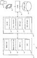
도 1은 본원에서 설명된 기법들에 따라 자동으로 구성될 수도 있는 저 필드 MRI 시스템의 개략적인 예시도이고;
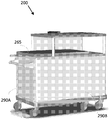
도 2a 및 도 2b는 일부 실시형태들에 따라, 휴대용 저 필드 MRI 시스템의 예시도이고;
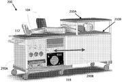
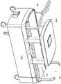
도 2c 및 도 2d는 일부 실시형태들에 따라, 수송가능한 저 필드 MRI 시스템의 예시도이고;
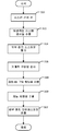
도 3은 일부 실시형태들에 따라 저 필드 MRI 시스템을 자동으로 구성하기 위한 프로세스의 플로우차트이고;
도 4는 일부 실시형태들에 따라 저 필드 MRI 시스템에 전력 공급(power up)하기 위한 프로세스의 플로우차트이고; 그리고
도 5는 본원에서 설명된 기법들의 일부가 수행될 수도 있는 네트워크화된 환경의 개략도이다.Various aspects and embodiments of the disclosed technology will be described with reference to the following drawings. It should be appreciated that the drawings are not necessarily drawn to scale.
1 is a schematic illustration of a low field MRI system that may be automatically configured according to the techniques described herein;
Figures 2a and 2b are exemplary views of a portable low field MRI system, in accordance with some embodiments;
Figures 2C and 2D are illustrations of a transportable low field MRI system, in accordance with some embodiments;
3 is a flow chart of a process for automatically configuring a low field MRI system in accordance with some embodiments;
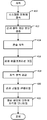
4 is a flow chart of a process for powering up a low field MRI system in accordance with some embodiments; And
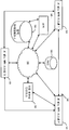
5 is a schematic diagram of a networked environment in which some of the techniques described herein may be performed.
MRI 스캐너 시장은 고 필드 시스템들에 의해 압도적으로 지배되고, 의료적 또는 임상적 MRI 응용들에 대하여 배타적으로 그러하다. 위에서 논의된 바와 같이, 의료적 이미징에서의 일반적인 추세는 점점 더 큰 필드 강도들을 갖는 MRI 스캐너들을 생성하여 왔고, 막대한 다수의 임상적 MRI 스캐너들은 1.5 T 또는 3 T에서 동작하고, 7 T 및 9 T의 더 고 필드 강도들이 연구 설정들에서 이용된다. 본원에서 이용된 바와 같이, "고 필드"는 임상적 설정에서 현재 이용 중인 MRI 시스템들, 및 더욱 상세하게는, 1.5 T 에서, 또는 1.5 T를 초과하는 주 자기장(즉, B0 필드)으로 동작하는 MRI 시스템들을 일반적으로 지칭하지만, .5 T 내지 1.5 T 사이에서 동작하는 임상적 시스템들이 "고 필드"로 일반적으로 또한 고려된다. 대조적으로, "저 필드"는 대략 0.2 T 이하의 B0 필드로 동작하는 MRI 시스템들을 일반적으로 지칭한다. 고 필드 MRI 시스템들의 매력은 더 저 필드 시스템들과 비교하여 개선된 해상도 및/또는 감소된 스캔 시간들을 포함하여, 임상적 및 의료적 MRI 응용들을 위한 점점 더 고 필드 강도들에 대한 압박을 자극한다.The market for MRI scanners is overwhelmingly dominated by high-field systems and is exclusively for medical or clinical MRI applications. As discussed above, the general trend in medical imaging has been to generate MRI scanners with increasingly larger field intensities, and a vast majority of clinical MRI scanners operate at 1.5 T or 3 T, and 7 T and 9 T Are used in the study settings. As used herein, the term "high field" refers to MRI systems currently in use in clinical settings, and more particularly, at 1.5 T, or with a main magnetic field (i.e., B 0 field) MRI systems, but clinical systems operating between .5 T and 1.5 T are generally also considered "high field ". In contrast, a "low field " generally refers to MRI systems operating with a B 0 field of approximately 0.2 T or less. The appeal of high field MRI systems, including improved resolution and / or reduced scan times compared to lower field systems, stimulates the pressure on increasingly higher field intensities for clinical and medical MRI applications .
발명자들은 병원들 및 연구 시설들에서의 설비들을 포함하지만, 또는 이것을 초월하는 다양한 환경들에서 MRI 기술의 대규모 전개가능성(deployability)을 개선시킬 수 있는 개선된 품질의, 휴대용, 및/또는 더욱 저비용인 저 필드 MRI 시스템들을 생성하기 위한 기법들을 개발하였다. 예를 들어, 병원들 및 연구 시설들에 추가하여, 저 필드 MRI 시스템들은 영구적 또는 반-영구적 설비들로서 중의 어느 하나로서, 사물실들, 전문병원들, 병원 내의 다수의 부서들(예컨대, 응급실들, 수술실들, 방사선학 부서들 등)에서 전개될 수도 있거나, 희망하는 로케이션(location)들로 수송될 수 있는 이동식/휴대용/운반가능한 시스템들로서 전개될 수도 있다.The inventors have discovered that improved quality, portable, and / or lower cost devices that can improve the large scale deployability of MRI technology in a variety of environments, including, but not limited to, facilities in hospitals and research facilities We have developed techniques for generating low field MRI systems. For example, in addition to hospitals and research facilities, low field MRI systems are either permanent or semi-permanent facilities, such as object rooms, specialty hospitals, multiple departments within a hospital (e.g., emergency rooms , Operating rooms, radiology departments, etc.), or may be deployed as portable / portable / portable systems that can be transported to the desired locations.
발명자들은 이러한 저 필드 MRI 시스템들의 광범위한 전개는 MRI 시스템이 시스테이 동작되는 임의의 환경에서 적당하게 수행하는 것을 보장함에 있어서 과제들을 제시한다는 것을 인지하였다. 특정한 환경 및/또는 응용을 위하여 저 필드 MRI 시스템의 파라미터들을 수동으로 구성하는 것은 번거롭고, 저 필드 MRI 시스템의 전형적인 사용자들이 가지지 않을 수도 있는 기술적 전문지식을 종종 요구한다. 추가적으로, 시스템의 동작에 대해 중요할 수도 있는 환경의 성질들은 인간 조작자에 의해 확인가능하거나, 또는 그렇지 않을 경우에 획득가능하지 않을 수도 있다.The inventors have recognized that the widespread deployment of these low field MRI systems presents challenges in ensuring that the MRI system performs properly in any environment where the system is operated. Manually configuring the parameters of a low field MRI system for a particular environment and / or application is cumbersome and often requires technical expertise that typical users of low field MRI systems may not have. Additionally, properties of the environment that may be important to the operation of the system may be identifiable by a human operator, or otherwise not obtainable.
따라서, 일부 실시형태들은 저 필드 MRI 시스템의 환경 및/또는 동작 조건에 적어도 부분적으로 기초하여 저 필드 MRI 시스템을 자동으로 구성하기 위한 기법들에 관한 것이다. 자동 구성을 위한 기법들은 이하에서 더욱 상세하게 논의된 바와 같이, 환경 및/또는 동작 조건들에서, 또는 임의의 다른 적당한 시간에서 하나 이상의 변화들을 검출하는 것에 응답하여, 시스템의 전력 온(power on) 시에 수행될 수도 있다. 일부 양태들은 시스템의 컴포넌트(들)가 저 필드 MRI 시스템이 동작되는 환경 및/또는 동작 조건들에 적어도 부분적으로 기초하여 자동으로 구성되는 저 필드 MRI 시스템을 위한 자동 설정 프로세스에 관한 것이다. 일부 양태들은 변화하는 환경 및/또는 동작 조건들을 고려하여 MRI 시스템을 동적으로 구성하는 것에 관한 것이다. 일부 양태들은 시스템의 동작 모드(예컨대, 저전력 모드, 워밍 업(wram-up), 아이들(idle) 등)에 기초하여 시스템의 동작을 조절하기 위한 자동 기법들에 관한 것이다.Accordingly, some embodiments are directed to techniques for automatically configuring a low field MRI system based at least in part on the environmental and / or operating conditions of a low field MRI system. Techniques for automatic configuration include power on of the system in response to detecting one or more changes in environmental and / or operating conditions, or at any other suitable time, as discussed in more detail below. . ≪ / RTI > Some aspects relate to an automatic setup process for a low field MRI system in which the component (s) of the system are automatically configured based at least in part on the environment and / or operating conditions under which the low field MRI system is operating. Some aspects relate to dynamically configuring an MRI system in view of changing environmental and / or operating conditions. Some aspects relate to automated techniques for adjusting the operation of a system based on the operating mode of the system (e.g., low power mode, wram-up, idle, etc.).
추가적으로, 위에서 논의된 바와 같이, MRI 시스템들의 필드 강도를 증가시키는 것은 점점 더 비싸고 복잡한 MRI 스캐너들을 산출하고, 이에 따라, 이용가능성을 제한하고, 일반적인 목적 및/또는 일반적으로 이용가능한 이미징 해결책으로서의 그 이용을 방지한다. 고 필드 MRI의 상대적으로 높은 비용, 복잡도, 및 크기는 그 이용을 전용 시설들로 주로 한정한다. 또한, 기존의 고 필드 MRI 시스템들은 희망하는 이미지들을 생성할 수 있기 위하여 시스템에 대한 대규모 훈련을 가졌던 기술자들에 의해 전형적으로 동작된다. 고도로 훈련된 기술자들이 고 필드 MRI 시스템들을 동작시키기 위하여 존재해야 한다는 요건은 고 필드 MRI의 제한된 이용가능성과, 폭넓게 이용가능한 및/또는 일반 목적의 이미징 해결책으로서 채용되도록 하기 위한 고 필드 MRI의 무능력에 추가로 기여한다.Additionally, increasing the field strength of MRI systems, as discussed above, may result in increasingly more expensive and complex MRI scanners, thereby limiting their availability and increasing their use as a general purpose and / or generally available imaging solution . The relatively high cost, complexity, and size of high field MRIs largely limit their use to dedicated facilities. In addition, existing high field MRI systems are typically operated by engineers who have had extensive training on the system to be able to produce the desired images. The requirement that highly trained technicians exist in order to operate high field MRI systems is in addition to the limited availability of high field MRI and the inability of high field MRI to be employed as a widely available and / or general purpose imaging solution .
발명자들은 이용의 용이함은 저 필드 MRI 시스템들이 다양한 상황들 및 환경들에서 폭넓게 이용가능하고, 전개되고, 및/또는 이용되는 것을 허용함에 있어서 상당한 기여 인자일 수도 있다는 것을 인지하였다. 이 목적을 위하여, 발명자들은 저 필드 MRI 시스템의 간단하고 직관적인 이용을 가능하게 하는 자동, 반-자동, 및/또는 보조된 설정 기법들을 개발하였다. 그 결과, 이러한 저 필드 MRI 시스템을 동작시키기 위하여 필요한 훈련의 양은 실질적으로 감소될 수도 있어서, 저 필드 MRI 시스템이 희망하는 이미징 응용들을 수행하기 위하여 채용될 수 있는 상황들을 증가시킬 수도 있다.The inventors have appreciated that ease of use may be a significant contributing factor in allowing low field MRI systems to be widely available, developed, and / or exploited in a variety of situations and environments. For this purpose, the inventors have developed automatic, semi-automated, and / or assisted setup techniques that enable simple and intuitive use of low field MRI systems. As a result, the amount of training required to operate such a low field MRI system may be substantially reduced, thereby increasing the circumstances in which a low field MRI system may be employed to perform the desired imaging applications.
저 필드 MRI를 포함하는 저 필드 자기 공명 응용들을 위한 방법들 및 장치에 관련된 다양한 개념들 및 이 방법들 및 장치의 실시형태들의 더욱 상세한 설명들이 이하에서 뒤따른다. 본원에서 설명된 다양한 양태들은 많은 방법들 중의 임의의 것으로 구현될 수도 있다는 것이 인식되어야 한다. 특정 구현예들의 예들은 오직 예시적인 목적들을 위하여 본원에서 제공된다. 게다가, 이하의 실시형태들에서 설명된 다양한 양태들은 단독으로 또는 임의의 조합으로 이용될 수도 있고, 본원에서 명시적으로 설명된 조합들로 제한되지 않는다. 본원에서 설명된 기법들의 일부가 저 필드 및/또는 휴대용 MRI와 연관된 과제들을 해결하도록 적어도 부분적으로 설계되었지만, 양태들이 임의의 특정한 타입의 MRI 시스템과의 이용을 위하여 제한되지 않으므로, 이 기법들은 이 점에서 제한되지 않고 고 필드 MRI 시스템들에 적용될 수 있다.Various concepts related to methods and apparatus for low field magnetic resonance applications, including low field MRI, and more detailed descriptions of embodiments of these methods and apparatus are provided below. It should be appreciated that the various aspects described herein may be implemented in any of a number of ways. Examples of specific implementations are provided herein for illustrative purposes only. In addition, the various aspects described in the following embodiments may be used singly or in any combination, and are not limited to the combinations explicitly described herein. Although some of the techniques described herein have been designed at least in part to address the challenges associated with low field and / or portable MRI, as these aspects are not limited for use with any particular type of MRI system, Lt; RTI ID = 0.0 > MRI < / RTI > systems.
도 1은 저 필드 MRI 시스템(100)의 예시적인 컴포넌트들의 블록도이다. 도 1의 예시적인 예에서, 저 필드 MRI 시스템(100)은 워크스테이션(workstation; 104), 제어기(106), 펄스 시퀀스들 저장소(108), 전력 관리 시스템(110), 및 자기기기 컴포넌트들(120)을 포함한다. 시스템(100)은 예시적이고, 저 필드 MRI 시스템은 도 1에서 예시된 컴포넌트들에 추가하여 또는 그 대신에, 임의의 적당한 타입의 하나 이상의 다른 컴포넌트들을 가질 수도 있다는 것이 인식되어야 한다.1 is a block diagram of exemplary components of a low
도 1에서 예시된 바와 같이, 자기기기 컴포넌트들(120)은 자석(122), 심 코일들(124), RF 송신/수신 코일들(126), 및 경사 코일(gradient coil)들(128)을 포함한다. 자석(122)은 주 자기장 B0을 생성하기 위하여 이용될 수도 있다. 자석(122)은 저 필드 강도를 가지는 주 자기장(즉, 0.2 테슬라(Tesla) 이하의 강도를 가지는 자기장)을 생성할 수 있는 임의의 적당한 타입의 자석일 수도 있다. 심 코일들(124)은 자석(122)에 의해 생성된 B0 필드의 균질성(homogeneity)을 개선시키도록 자기장(들)에 기여하기 위하여 이용될 수도 있다. 경사 코일들(128)은 경사 필드(gradient field)들을 제공하도록 배열될 수도 있고, 예를 들어, 3 개의 실질적으로 직교하는 방향들(X, Y, Z)로 자기장에서 경사(gradient)들을 생성하도록 배열될 수도 있다.1, the
RF 송신/수신 코일들(126)은 발진하는 주 자기장 B1을 유도하기 위한 RF 펄스들을 생성하기 위하여 이용될 수도 있는 하나 이상의 송신 코일들을 포함한다. 송신 코일(들)은 저 필드 MR 이미징을 수행하기 위하여 유용한 임의의 적당한 타입들의 RF 펄스들을 생성하도록 구성될 수도 있다. 일부 실시형태들에서, 저 필드 MR 이미징을 수행하기 위하여 유용한 적당한 타입들의 RF 펄스들은 이하에서 더욱 상세하게 논의된 바와 같이, 환경 조건들에 대해 적어도 부분적으로 선택될 수도 있다.And the RF transmit / receive
자기기기 컴포넌트들(120)의 각각은 임의의 적당한 방법으로 구성될 수도 있다. 예를 들어, 일부 실시형태들에서, 자기기기 컴포넌트들(120) 중의 하나 이상은, 그 전체적으로 참조로 본원에 편입되는, 2015년 9월 4일자로 출원된, "Low Field Magnetic Resonance Imaging Methods and Apparatus(저 필드 자기 공명 이미징 방법들 및 장치)"라는 명칭인, 대리인 관리번호: 제O0354.70000US01호 하에서의 공동-출원된 미국 출원에서 설명된 기법들을 이용하여 제작될 수도 있다.Each of the
전력 관리 시스템(110)은 동작 전력을 저 필드 MRI 시스템(100)의 하나 이상의 컴포넌트들에 제공하기 위한 전자기기를 포함한다. 예를 들어, 이하에서 더욱 상세하게 논의된 바와 같이, 전력 관리 시스템(110)은 하나 이상의 전력 공급 장치들, 경사 전력 증폭기(gradient power amplifier)들, 송신 코일 증폭기들, 및/또는 저 필드 MRI 시스템(100)의 컴포넌트들을 급전시키고 동작시키기 위하여 적당한 동작 전력을 제공하기 위하여 필요한 임의의 다른 적당한 전력 전자기기들을 포함할 수도 있다.The
도 1에서 예시된 바와 같이, 전력 관리 시스템(110)은 전력 공급 장치(112), 증폭기(들)(114), 송신/수신 스위치(116), 및 열 관리 컴포넌트들(118)을 포함한다. 전력 공급 장치(112)는 동작 전력을 저 필드 MRI 시스템(100)의 자기적 컴포넌트들(120)에 제공하기 위한 전자기기들을 포함한다. 예를 들어, 전력 공급 장치(112)는 저 필드 MRI 시스템을 위한 주 자기장을 생성하기 위하여 동작 전력을 하나 이상의 B0 코일들(예컨대, B0 자석(122))에 제공하기 위한 전자기기들을 포함할 수도 있다. 일부 실시형태들에서, 전력 공급 장치(112)는 단극성의 연속파(continuous wave; CW) 전력 공급 장치이지만, 그러나, 임의의 적당한 전력 공급 장치가 이용될 수도 있다. 송신/수신 스위치(116)는 RF 송신 코일들 또는 RF 수신 코일들이 동작되고 있는지 여부를 선택하기 위하여 이용될 수도 있다.As illustrated in FIG. 1, the
증폭기(들)(114)는 하나 이상의 RF 수신 코일들(예컨대, 코일들(124))에 의해 검출된 MR 신호들을 증폭시키는 하나 이상의 RF 수신(RX) 전치-증폭기(pre-amplifier)들, 전력을 하나 이상의 RF 송신 코일들(예컨대, 코일들(126))에 제공하도록 구성된 하나 이상의 RF 송신(Tx) 증폭기들, 전력을 하나 이상의 경사 코일들(예컨대, 경사 코일들(128))에 제공하도록 구성된 하나 이상의 경사 전력 증폭기들, 전력을 하나 이상의 심 코일들(예컨대, 심 코일들(124))에 제공하도록 구성된 심 증폭기들을 포함할 수도 있다.The amplifier (s) 114 may include one or more RF receive (RX) pre-amplifiers that amplify the MR signals detected by one or more RF receive coils (e.g., coils 124) One or more RF transmit (Tx) amplifiers configured to provide power to one or more RF transmit coils (e.g., coils 126), power to one or more bevel coils (e.g., bevel coils 128) One or more gradient power amplifiers configured, and shim amplifiers configured to provide power to one or more shim coils (e.g., the shim coils 124).
열 관리 컴포넌트들(118)은 저 필드 MRI 시스템(100)의 컴포넌트들을 위한 냉각을 제공하고, 그 컴포넌트들로부터 멀어지도록, 저 필드 MRI 시스템(100)의 하나 이상의 컴포넌트들에 의해 생성된 열 에너지의 전달을 가능하게 함으로써 그렇게 행하도록 구성될 수도 있다. 열 관리 컴포넌트들(118)은, B0 코일들, 경사 코일들, 심 코일들, 및/또는 송신/수신 코일들을 포함하지만, 이것으로 제한되지는 않는, 열을 생성하는 MRI 컴포넌트들과 통합될 수도 있거나 MRI 컴포넌트들에 밀접하게 근접하도록 배열될 수도 있는, 물-기반 또는 공기-기반 냉각을 수행하기 위한 컴포넌트들을 제한 없이 포함할 수도 있다. 열 관리 컴포넌트들(118)은 저 필드 MRI 시스템(100)의 컴포넌트들로부터 열을 멀리 전달하기 위하여, 물 및 공기를 포함하지만, 이것으로 제한되지 않는 임의의 적당한 열 전달 매체를 포함할 수도 있다. 열 관리 컴포넌트는 예를 들어, 그 전체적으로 참조로 본원에 편입되는, 2015년 9월 4일자로 출원된, "Thermal Management Methods and Apparatus(열 관리 방법들 및 장치)"라는 명칭인, 대리인 관리 번호: 제O0354.70004US01호 하에서의 공동-출원된 미국 출원에서 설명된 열 관리 컴포넌트들 및/또는 기법들 중의 임의의 것일 수도 있다.The
도 1에서 예시된 바와 같이, 저 필드 MRI 시스템(100)은 명령들을 전력 관리 시스템(110)으로 전송하고 전력 관리 시스템(110)으로부터 정보를 수신하기 위한 제어 전자기기들을 가지는 제어기(106)(콘솔(console)로서 본원에서 또한 지칭됨)를 포함한다. 제어기(106)는 희망하는 시퀀스로 자기적 컴포넌트들(120) 중의 하나 이상을 동작시키기 위하여 전력 관리 시스템(110)으로 전송된 명령들을 결정하기 위하여 이용되는 하나 이상의 펄스 시퀀스(pulse sequence)들을 구현하도록 구성될 수도 있다. 본원에서 제공된 개시물의 양태들이 이 점에서 제한되지 않으므로, 제어기(106)는 하드웨어, 소프트웨어, 또는 하드웨어 및 소프트웨어의 임의의 적당한 조합으로서 구현될 수도 있다.1, a low
일부 실시형태들에서, 제어기(106)는 하나 이상의 펄스 시퀀스들의 각각에 대한 정보를 저장하는 펄스 시퀀스들 저장소(pulse sequences repository; 108)로부터 펄스 시퀀스에 대한 정보를 획득함으로써 펄스 시퀀스를 구현하도록 구성될 수도 있다. 특정한 펄스 시퀀스를 위한 펄스 시퀀스들 저장소(108)에 의해 저장된 정보는 제어기(106)가 특정한 펄스 시퀀스를 구현하는 것을 허용하는 임의의 적당한 정보일 수도 있다. 예를 들어, 펄스 시퀀스를 위한 펄스 시퀀스들 저장소(108)에서 저장된 정보는 펄스 시퀀스에 따라 자기적 컴포넌트들(120)을 동작시키기 위한 하나 이상의 파라미터들(예컨대, RF 송신/수신 코일들(126)을 동작시키기 위한 파라미터들, 경사 코일들(128)을 동작시키기 위한 파라미터들 등), 펄스 시퀀스에 따라 전력 관리 시스템(110)을 동작시키기 위한 하나 이상의 파라미터들, 제어기(106)에 의해 실행될 때, 제어기(106)로 하여금, 펄스 시퀀스에 따라 동작하도록 시스템(100)을 제어하게 하는 명령들을 포함하는 하나 이상의 프로그램들, 및/또는 임의의 다른 적당한 정보를 포함할 수도 있다. 펄스 시퀀스들 저장소(108)에서 저장된 정보는 하나 이상의 비-일시적(non-transitory) 저장 매체들 상에 저장될 수도 있다.In some embodiments, the
도 1에서 예시된 바와 같이, 제어기(106)는 또한, 수신된 MR 데이터를 프로세싱하도록 프로그래밍된 컴퓨팅 디바이스(104)와 상호작용한다. 예를 들어, 컴퓨팅 디바이스(104)는 임의의 적당한 이미지 재구성 프로세스(들)를 이용하여 하나 이상의 MR 이미지들을 생성하기 위하여 수신된 MR 데이터를 프로세싱할 수도 있다. 제어기(106)는 컴퓨팅 디바이스에 의한 MR 데이터의 프로세싱을 가능하게 하기 위하여, 하나 이상의 펄스 시퀀스들에 대한 정보를 컴퓨팅 디바이스(104)에 제공할 수도 있다. 예를 들어, 제어기(106)는 하나 이상의 펄스 시퀀스들에 대한 정보를 컴퓨팅 디바이스(104)에 제공할 수도 있고, 컴퓨팅 디바이스는 제공된 정보에 적어도 부분적으로 기초하여 이미지 재구성 프로세스를 수행할 수도 있다.As illustrated in FIG. 1, the
컴퓨팅 디바이스(104)는, 취득된 MR 데이터를 프로세싱하고 이미징되고 있는 대상자의 하나 이상의 이미지들을 생성하도록 구성된 임의의 전자 디바이스일 수도 있다. 일부 실시형태들에서, 컴퓨팅 디바이스(104)는, MR 데이터를 프로세싱하고 이미징되고 있는 대상자의 하나 이상의 이미지들을 생성하도록 구성될 수도 있는 데스크톱 컴퓨터, 서버, 랙-장착형(rack-mounted) 컴퓨터, 또는 임의의 다른 적당한 고정된 전자 디바이스와 같은 고정된 전자 디바이스일 수도 있다. 대안적으로, 컴퓨팅 디바이스(104)는, MR 데이터를 프로세싱하고 이미징되고 있는 대상자의 하나 또는 이미지들을 생성하도록 구성될 수도 있는 스마트 폰, 개인 정보 단말, 랩톱 컴퓨터, 태블릿 컴퓨터, 또는 임의의 다른 휴대용 디바이스와 같은 휴대용 디바이스일 수도 있다. 일부 실시형태들에서, 본원에서 제공된 개시물의 양태들이 이 점에서 제한되지 않으므로, 컴퓨팅 디바이스(104)는 임의의 적당한 타입의 다수의 컴퓨팅 디바이스들을 포함할 수도 있다. 사용자(102)는 저 필드 MR 시스템(100)의 양태들을 제어하고(예컨대, 특정한 펄스 시퀀스에 따라 동작하도록 시스템(100)을 프로그래밍하고, 시스템(100)의 하나 이상의 파라미터들을 조절하는 등) 및/또는 저 필드 MR 시스템(100)에 의해 획득된 이미지들을 시청하기 위하여 컴퓨팅 디바이스(104)와 상호작용할 수도 있다.The
도 2a 및 도 2b는 일부 실시형태들에 따라, 휴대용 또는 운반가능한 저 필드 MRI 시스템(200)을 예시한다. 시스템(200)은 도 1과 관련하여 위에서 설명된 컴포넌트들 중의 하나 이상을 포함할 수도 있다. 예를 들어, 시스템(200)은 단일의 일반적으로 수송가능하고 변형가능한 구조체 상에 함께 배열된, 자기적 및 전력 컴포넌트들 및 잠재적으로 다른 컴포넌트들(예컨대, 열 관리, 콘솔 등)을 포함할 수도 있다. 시스템(200)은 적어도 2 개의 구성들: 수송 및 보관을 위하여 구비된 구성, 및 동작을 위하여 구비된 구성을 가지도록 설계될 수도 있다. 도 2a는 수송 및/또는 보관을 위하여 고정될 때의 시스템(200)을 도시하고, 도 2b는 동작을 위하여 변형될 때의 시스템(200)을 도시한다. 시스템(200)은 도 2b에서 도시된 화살표들에 의해 표시된 바와 같이, 시스템을 그 수송 구성으로부터 그 동작 구성으로 변형할 때에 부분(290B)으로 슬라이딩될 수 있고 부분(290B)으로부터 후퇴될 수 있는 부분(290A)을 포함한다. 부분(290A)은 전력 전자기기(110), (도 2a 및 도 2b에서 예시된 터치 패널 디스플레이와 같은 인터페이스 디바이스를 포함할 수도 있는) 콘솔(106), 및 열 관리부(118)를 실장할 수도 있다. 부분(290 A)은 또한, 시스템(200)을 필요한 대로 동작시키기 위하여 이용된 다른 컴포넌트들을 포함할 수도 있다.2A and 2B illustrate a portable or portable low
부분(290B)은, 하나 이상의 자기적 컴포넌트들(예컨대, 자석(112), 심 코일들(124), RF 송신/수신 코일들(126), 경사 코일들(128))이 임의의 구성으로 그 위에 통합되는 라미네이트 패널들(210A 및 210B)을 포함하는, 저 필드 MRI 시스템(200)의 자기적 컴포넌트들(120)을 포함한다. (도 2b에서 도시된 바와 같이) MRI를 수행하도록 시스템을 동작시키기 위하여 구비된 구성으로 변형될 때, 부분들(290A 및 290B)의 지지 표면들은 이미징되어야 할 대상자가 그 위에 누울 수 있는 표면을 제공한다. 슬라이딩가능한 표면(265)은 대상자의 부분이 대응하는 저 필드 MRI 자석들을 제공하는 라미네이트 패널들의 시야 내에 있도록 하는 위치로 대상자를 슬리이딩하는 것을 가능하게 하기 위하여 제공될 수도 있다. 시스템(200)은 그것이 기존에는 (예컨대, 응급실에서) 이용가능하지 않은 상화들에서 MRI 이미징에 대한 접근을 가능하게 하는 저 필드 MRI 시스템의 휴대용의 간결한 구성을 제공한다.
도 2c 및 도 2d는 일부 실시형태들에 따라, 또 다른 일반적으로 수송가능한 저 필드 MRI 시스템을 예시한다. 도 21c는 일부 실시형태들에 따라, 이중-평면 하이브리드 자석을 사용하는 전환가능한 저 필드 MRI 시스템(280)의 예를 예시한다. 도 2c에서, 전환가능한 시스템은 그것이 이용 중이지 않을 때에 시스템을 수송하거나 시스템을 보관하기 위해 편리한 접혀진 구성으로 되어 있다. 전환가능한 시스템(280)은, 인간 환자를 지지하고 환자가 화살표들(2281)의 방향으로 하우징들(286A 및 286B) 사이의 이미징 영역 내로 그리고 이미징 영역으로부터 슬라이딩되는 것을 허용하도록 구성된 슬라이딩가능한 침대(284)를 포함한다. 하우징들(286A 및 286B)은 MRI를 수행하기 위한 자기장들을 생성하기 위하여 전환가능한 시스템(280)을 위한 자기적 컴포넌트들을 실장한다. 일부 실시형태들에 따르면, 자기적 컴포넌트들은 라미네이트 기법들을 배타적으로 이용하여, 전통적인 기법들을 배타적으로 이용하여, 또는 양자의 조합을 이용하여(예컨대, 하이브리드 기법들을 이용하여) 생성될 수도 있고, 제조될 수도 있고, 배열될 수도 있다.Figures 2C and 2D illustrate another generally transportable low field MRI system, in accordance with some embodiments. Figure 21C illustrates an example of a switchable low
도 2d는 이미징되어야 할 하우징들(286A 및 286B) 사이에 삽입되기 이전에 슬라이딩가능한 침대(284) 상에 위치된 환자를 갖는, 연장된 전환가능한 시스템(280)을 예시한다. 일부 실시형태들에 따르면, 하우징들(286A 및 286B)의 각각은 자기적 컴포넌트들로부터 멀어지도록 열을 끌어들이기 위한 열 관리 컴포넌트에 결합된 하이브리드 자석을 실장한다. 구체적으로, 이미징 영역의 대향하는 면들 상의 하우징들(286A 및 286B)의 각각은 B0 코일들(205a 및 205b), 라미네이트 패널(210)(얼굴-상향 배열에서 하우징(286B) 내에서 가시적인 210b), 및 B0 코일들 사이에 제공된 열 관리 컴포넌트(230)를 그 내부에 포함한다. 양태들이 하이브리드 자석의 임의의 특정한 설계 또는 구성과의 이용을 위하여 제한되지 않으므로, 286A 및 286B에서 실장된 자기적 컴포넌트들은 대칭적인 이중-평면 하이브리드 자석을 형성하기 위하여 실질적으로 동일할 수도 있거나, 286A 및 286B에서 실장된 자기적 컴포넌트들은 비대칭적인 이중-평면 하이브리드 자석을 형성하기 위하여 상이할 수도 있다.Figure 2D illustrates an elongated,
본원에서 설명된 기법들에 따라, 저 필드 MRI 시스템(예컨대, 시스템(100, 200, 및/또는 280))의 하나 이상의 컴포넌트들은 시스템이 동작 동안에 적절하게 수행할 것이거나 수행하고 있다는 것을 보장하도록 자동으로 구성된다. 위에서 논의된 바와 같이, 이러한 MRI 시스템은 주어진 환경에서 만족스러운 동작을 보장하기 위하여, 시스템의 하나 이상의 파라미터들이 조절될 것을 요구하는 다양한 환경들에서 동작될 수도 있다. 또한, 위에서 논의된 바와 같이, 저 필드 MRI 시스템의 컴포넌트들의 수동 구성은 번거롭고, MRI 시스템의 많은 사용자들이 가지지 않을 수도 있는 전문지식을 요구한다. 많은 사례들에서, 시스템이 조절하거나 적응할 필요가 있는 환경 및/또는 동작 조건은 인간 조작자에게 확인가능하지 않을 수도 있어서(예컨대, 라디오 주파수 잡음 또는 다른 전자기 간섭(electromagnetic interference; EMI), 의도적이지 않은 단락 또는 개방 회로들, 오정렬된 컴포넌트들 등), 시스템에 대한 적절한 조절은 심지어 전문가에도 가능하지 않다. 따라서, 일부 실시형태들은 특정한 이벤트(예컨대, 저 필드 MRI 시스템의 전력 온, 슬립 모드 또는 저전력 모드로부터의 웨이크-업, 변화하는 환경 조건들의 검출 등)의 발생에 응답하여 구성 및/또는 설정 동작들의 세트를 자동으로 수행하도록 구성된다.In accordance with the techniques described herein, one or more components of a low field MRI system (e.g.,
도 3은 일부 실시형태들에 따라, 이벤트의 발생에 응답하여 수행될 수도 있는 자동 구성 프로세스를 예시한다. 도 3은 수행될 수도 있는 다수의 구성 또는 설정 동작들을 예시하지만, 양태들이 이 점에서 제한되지 않으므로, 동작들 중의 임의의 하나 또는 조합이 수행될 수도 있다는 것이 인식되어야 한다. 추가적으로, 도 3에서 도시된 예시적인 구성 동작들이 직렬로 수행되는 것으로서 도시되지만, 하나 이상의 구성 동작들이 부분적으로 또는 완전히 병렬로 수행될 수도 있고, 어느 특정한 구성 동작들이 수행되는지 및/또는 특정한 구성 동작들이 언제 수행되는지에 대한 제한들이 없다는 것이 인식되어야 한다.Figure 3 illustrates an automatic configuration process that may be performed in response to the occurrence of an event, in accordance with some embodiments. 3 illustrates a number of configuration or setting operations that may be performed, but it should be appreciated that any one or combination of the operations may be performed, as aspects are not limited in this respect. Additionally, while the exemplary configuration operations depicted in FIG. 3 are shown as being performed in series, one or more configuration operations may be performed partially or completely in parallel, and that certain specific configuration operations are performed and / It should be appreciated that there are no limitations on when it is performed.
액트(act)(310)에서, 저 필드 MRI 시스템이 전력 온 된다. 도 4는 일부 실시형태들에 따라 액트(310)에서 수행될 수도 있는 전력 온 프로세스를 예시한다. 도 4는 수행될 수도 있는 다수의 전력-공급(power-up) 동작들을 예시하지만, 양태들이 이 점에서 제한되지 않으므로, 동작들 중의 임의의 하나 또는 조합이 수행될 수도 있다는 것이 인식되어야 한다. 추가적으로, 도 4에서 도시된 예시적인 구성 동작들이 직렬로 수행되는 것으로서 도시되지만, 하나 이상의 구성 동작들이 부분적으로 또는 완전히 병렬로 수행될 수도 있고, 어느 특정한 구성 동작들이 수행되는지 및/또는 특정한 구성 동작들이 언제 수행되는지에 대한 제한들이 없다는 것이 인식되어야 한다.At
액트(410)에서, 저 필드 MRI 시스템은 전원에 접속된다. 예를 들어, 저 필드 MRI 시스템은 표준 벽 접속구(wall outlet)에 접속될 수도 있거나, 발전기와 같은 외부 전력 공급 장치에 접속될 수도 있거나, 동작 전력을 저 필드 MRI 시스템의 컴포넌트들에 제공하기 위한 임의의 다른 적당한 타입의 전원에 접속될 수도 있다. 액트(412)에서, 긴급 전력 차단이 동작하는지가 검증된다. 환자 안전은 의료적 디바이스들을 설계할 때에 주요한 고려사항이다. 따라서, 본원에서 설명된 기법들에 따라 이용된 일부 저 필드 MRI 시스템들은 환자 안전이 걱정일 수도 있는 상황들(예컨대, 자석의 과열)에서 수동으로 또는 자동으로 트리거링될 수도 있는 긴급 전력 차단을 포함한다. 이에 따라, 안전한 동작을 보장하기 위하여, 시스템은 임의의 그리고 모든 전력 차단(또는 다른 안전 메커니즘들)이 인에이블(enable)되고 및/또는 동작하는지를 확인할 것을 검사할 수도 있다.In
액트(414)에서, 콘솔(console)(104)은 예를 들어, 사용자가 콘솔 상의 전력 스위치, 버튼, 또는 다른 메커니즘을 누름으로써 전력 온 된다. 전력 온 되는 것에 응답하여, 콘솔은 저 필드 MRI 시스템의 하나 이상의 동작들을 제어하기 위하여 이용된 제어 애플리케이션을 기동(launch)하기 이전에 다수의 시동(startup) 프로세스들을 실행할 수도 있다. 임의의 시동 프로세스들의 실행 후에 또는 실행 동안에, 저 필드 MRI 시스템의 하나 이상의 동작들을 제어하도록 구성된 제어 애플리케이션은 콘솔 상에서 기동된다(액트(416)). 제어 애플리케이션은 이하에서 더욱 상세하게 논의된 바와 같이, 콘솔의 전력 온 시에, 또는 콘솔, 또는 콘솔과 상호작용하도록 구성된 외부 전자 디바이스와의 사용자 상호작용에 응답하여, 자동으로 기동될 수도 있다. 제어 애플리케이션이 기동되는 것에 응답하여, 애플리케이션은 시스템 DC 전력을 턴 온(turn on) 할 것을 전력 공급 장치(112)에 명령하는 것을 포함하지만, 이것으로 제한되지 않는 하나 이상의 동작들을 수행할 것을 콘솔에 명령할 수도 있다.In
제어 애플리케이션의 기동 후에 또는 기동 동안에, 저 필드 MRI 시스템의 다른 컴포넌트들은 인에이블될 수도 있고 및/또는 구성될 수도 있다. 예를 들어, 액트(418)에서, 제어 애플리케이션은 자석을, 결과적인 B0 필드가 예를 들어, 저 필드 MRI를 수행하기 위한 이미징을 위하여 적당한 온도로 워밍 업함으로써, 자석(122)에 전력 공급할 것을 전력 공급 장치(112)에 명령할 수도 있다. 일부 구현예들에서, 자석을 워밍 업하는 프로세스는 이미징을 위하여 적당한 안정된 B0 필드를 제공하기 위하여 상당한 시간량(예컨대, 30 분)이 걸릴 수도 있다. 자석(122)을 워밍 업하기 위하여 필요한 시간량을 감소시키기 위하여, 일부 실시형태들은 하나 이상의 "예열(pre-heating)" 동작들을 수행한다. 예를 들어, 저 필드 MRI 시스템의 동작 동안에, 저 필드 MRI 시스템의 자기적 컴포넌트들(120)로부터 열을 멀리 전달하는 열 관리 컴포넌트들(118) 중의 하나 이상은 열 관리 컴포넌트들이 정상적으로 동작하고 있었을 경우보다 더 빨리 자석이 워밍 업하는 것을 허용하기 위하여 턴 다운(turn down) 또는 턴 오프(turn off) 될 수도 있다. 일부 실시형태들에서, 열 관리 컴포넌트들(118)은 저 필드 MRI 시스템의 자기기기 컴포넌트들의 냉각을 제공하기 위하여 공기 또는 물 냉각 시스템들(예컨대, 팬(fan)들 및/또는 펌프(pump)들)을 포함한다. 자석의 예열 동안, 팬들 및/또는 펌프들은 자석 워밍 업 프로세스를 촉진시키기 위하여 (예컨대, 냉각 용량 또는 세기를 감소시킴으로써) 턴 오프 또는 턴 다운 될 수도 있다. 하나 이상의 열 관리 컴포넌트들을 동작 용량 미만에서 동작시키는 것은 하나 이상의 열 관리 컴포넌트들을 전혀 동작시키지 않는 것에 의한 것을 포함하여, 열을 제거하기 위한 용량이 그 정상 동작으로부터 감소되도록 하나 이상의 열 관리 컴포넌트들을 의도적으로 조절하는 것을 본원에서 지칭한다.After activation or activation of the control application, other components of the low field MRI system may be enabled and / or configured. For example, in
열 관리 컴포넌트들(118)의 동작을 수정하는 실시형태들에서, 자석의 온도는 자석이 과열하지 않는다는 것을 보장하기 위하여, 및/또는 열 관리 컴포넌트들의 용량/세기를 언제 턴 온하거나 증가시킬 것인지를 결정하기 위하여 면밀하게 모니터링되어야 한다. 자석의 온도는 온도 센서를 이용하는 것, 자석의 측정된 전압에 적어도 부분적으로 기초하여 자석의 온도를 결정하는 것 등을 포함하지만, 이것으로 제한되지 않는 임의의 적당한 방법으로 결정될 수도 있다. 일부 실시형태들에 따르면, (예컨대, 센서들 및/또는 전압 측정들을 통한) 온도 감지는 워밍을 촉진시키도록, 및/또는 자석이 열 균형 또는 적당한 B0 필드 안정성에 접근할 때에 냉각 세기를 관여하고 및/또는 증가시키도록, 열 관리의 제어를 자동화하기 위하여 제공된다.In embodiments that modify the operation of the
일부 실시형태들은 시스템이 자석 워밍을 유지하기 위하여 아이들(예컨대, 이미징을 위하여 이용되지 않음)일 때의 이용을 위한 저전력 모드를 포함한다. 예를 들어, 저전력 모드에서는, 자석(112)이 이미징을 위하여 용인가능한 온도에서 유지되는 것을 허용하면서, 더 적은 전류가 자석에 제공될 수도 있다. 저전력 모드는 자석이 희망하는 온도에서 유지되는 것을 가능하게 하는 임의의 적당한 방법으로 구현될 수도 있다. 예를 들어, 자석의 워밍-업 시간을 감소시키기 위하여 위에서 설명된 기법들 중의 하나 이상(예컨대, 하나 이상의 열 관리 컴포넌트들을 턴 오프 또는 다운하는 것)은 또한, 저 필드 MRI 시스템을 저전력 모드로 설정하기 위하여 이용될 수도 있다. 이에 따라, 이용 중이지 않는 동안, 자석은 더 적은 전력으로 워밍 상태에 머물 수 있어서, 필요할 때, 자석은 워밍-업 주기를 필요로 하지 않으면서 준비된다. 일부 실시형태들에서, 저전력 모드에서의 동작은 저 필드 MRI 시스템(100)이 특정한 시간량 동안에 동작하고 있지 않았을 때에 자동으로 개시될 수도 있고, 및/또는 저전력 모드는 스위치, 버튼, 또는 시스템에 의해 제공된 다른 인터페이스 메커니즘에 의해 수동으로 개시될 수도 있다.Some embodiments include a low power mode for use when the system is idle (e.g., not used for imaging) to maintain magnet warming. For example, in the low power mode, less current may be applied to the magnet while allowing the
대안적으로, 저전력 모드는 저 필드 MRI 시스템(100)이 동작하고 있는 환경의 주변 온도가 특정한 온도를 초과하는 것으로 결정하는 것에 응답하여 이용될 수도 있다. 예를 들어, 저 필드 MRI 시스템이 고온 환경(예컨대, 사막)에서 전개될 경우, 정상 동작 모드에서의 자석의 동작은 자석 과열의 가능성으로 인해 가능하지 않을 수도 있다. 그러나, 이러한 상황들에서, MRI 시스템(100)은 더 낮은 온도들을 갖는 환경들에서 이용되었던 것보다 더 적은 전류로 자석을 구동함으로써 저전력 모드에서 동작할 수 있을 수도 있다. 따라서, 이러한 저전력 모드는 MRI 시스템들이 동작하기가 보통은 부적당할 환경들에 도전할 시에 저 필드 MRI 시스템들의 이용을 가능하게 한다.Alternatively, the low power mode may be used in response to determining that the ambient temperature of the environment in which the low
일부 실시형태들에서, 이미징 이전에 자석의 워밍 업을 수행하기 위하여 요구된 시간은 변동들이 안정화되기 전에 이미징을 가능하게 하기 위하여, 워밍 업 프로세스 동안에 저 필드 MRI 파라미터들에서의 변동들을 결정하고 이 변동들을 보상함으로써 감소될 수도 있다. 예를 들어, B0 자석의 라모어 주파수(Larmor frequency)는 자석이 워밍 업하고 안정적으로 될 때에 종종 변동된다. 일부 실시형태들은 어떻게 라모어 주파수가 자석의 전압(또는 온도)을 추적하고, 자석이 그 정상 동작 온도에 도달하기 전에 이미징을 허용하기 위하여 주파수에 있어서의 변화들을 보상하는지를 특징화한다. B0 필드의 균질성(homogeneity)은 자석의 워밍 업 동안에 변동하도록 알려진 또 다른 파라미터이다. 따라서, 일부 실시형태들은 어떻게 B0 필드 균질성이 자석의 전압(또는 온도)을 추적하고, 필드 균질성이 정상 동작 레벨들에 도달하기 전에 이미징을 가능하게 하기 위하여 (예컨대, 하나 이상의 심 코일들을 이용하여) 필드 균질성에 있어서의 변화들을 보상하는지를 특징화한다. 이 파라미터들에서의 변동들이 자석의 전압(또는 온도), 또는 저 필드 MRI 시스템의 일부 다른 파라미터들을 측정함으로써 특징화될 수도 있다면, 자석(112)의 워밍 업 동안에 변동되는 다른 저 필드 MRI 파라미터들은 또한, 자석이 열 균형 및/또는 필드 안정성에 도달하기 전에 저 필드 MRI 시스템에 의한 이미징을 제공하기 위하여 추적될 수도 있고 보상될 수도 있다.In some embodiments, the time required to perform the warm-up of the magnet prior to imaging determines the variations in the low field MRI parameters during the warm-up process to enable imaging before the variations stabilize, Lt; / RTI > For example, the Larmor frequency of the B 0 magnet often fluctuates when the magnet is warmed up and stable. Some embodiments characterize how the Ramore frequency tracks the voltage (or temperature) of the magnet and compensates for changes in frequency to permit imaging before the magnet reaches its normal operating temperature. The homogeneity of the B 0 field is another parameter known to fluctuate during the warm-up of the magnet. Thus, some embodiments (e.g., using one or more shim coils to enable imaging prior to how to reach the voltage (or temperature) the track, the field homogeneity is the normal operating level of the B 0 field homogeneity of the magnet ) To compensate for changes in field homogeneity. Other low field MRI parameters that vary during the warm-up of the
도 4의 프로세스로 돌아가면, 액트(420)에서, 경사 코일들이 인에이블된다. 발명자들은 일부 실시형태들에서, 경사 코일들을 인에이블하는 프로세스가 저 필드 MRI 시스템의 전력 소비를 감소시키기 위하여, 이미징이 진행하도록 준비되기 바로 전까지 지연될 수도 있다는 것을 인지하였다. 저 필드 MRI 시스템이 동작한 후, 액트(422)는 자석이 동작을 위하여 적당한 상태에서 유지되는 것을 보장하기 위하여 자석의 하나 이상의 성질들을 모니터링하도록 수행될 수도 있다. 자석의 하나 이상의 성질들이 만족스러운 이미지들을 취득하기 위한 능력에 영향을 주는 방식으로, 자석의 하나 이상의 성질들이 드리프트(drift)하였거나, 또는 그렇지 않을 경우에 변화한 것으로 검출될 경우, 하나 이상의 치유 액션들이 수행될 수도 있다.Returning to the process of FIG. 4, in
도 3의 프로세스로 돌아가면, 액트(312)에서, 하나 이상의 일반적인 시스템 검사들은 저 필드 MRI 시스템(100)의 적당한 동작을 보장하도록 수행된다. 예를 들어, 일반적인 시스템 검사들은 자석(112)이 단락되거나 개방되는지 여부를 검사하는 것을 포함할 수도 있다. 자석(112)의 단락은 다수의 이유들 중의 임의의 이유로 발생할 수도 있다. 예를 들어, 정상 동작 이용 동안, 및/또는 상이한 환경들에서의 동작의 결과로, 저 필드 MRI 시스템의 다양한 컴포넌트들의 열 수축 및 팽창(열 사이클링)은 MRI 시스템의 자석(112) 또는 그 부분, 또는 다양한 다른 회로부, 코일들 등 중의 임의의 것의 단락으로 귀착될 수도 있다. 예를 들어, 열 사이클링(thermal cycling)은 그렇지 않을 경우에, 격리된 전도성 재료가 시스템의 단락 회로부(예컨대, 코일에서의 권선들)에 접촉하게 할 수도 있다. 예를 들어, 열 관리 시스템(118)의 컴포넌트로서 포함된 냉각 판의 전도성(예컨대, 알루미늄) 표면은 일부 경우들에는, 코일의 단락을 야기시키기 위하여 냉각되는 하나 이상의 코일들의 전도성 재료와 접촉할 수도 있다. 일부 실시형태들은 단락이 있는지 여부를 결정하기 위하여 시스템(예컨대, 자석(112))을 테스트하고, 그러할 경우, 시스템이 동작하고 있지 않고 서비스될 필요가 있다는 경보가 사용자에게 제공될 수도 있다. 단락은 IV 곡선이 예상된 대로 응답하는지 여부를 평가하기 위하여 하나 이상의 컴포넌트들에 전력을 공급하는 것으로부터 기인하는 전류-전압(current-voltage; IV) 곡선을 모니터링함으로써, 또는 임의의 다른 적당한 기법을 이용함으로써 검출될 수도 있다.Returning to the process of FIG. 3, at
일부 실시형태들에 따르면, 시스템을 개방 회로에 대하여 검출한다. 예를 들어, 임의의 수의 인자들은 자석(112)(또는 임의의 다른 시스템 회로부)이 개방하게 할 수도 있음으로써, 전류가 흐르는 것을 허용하지 않을 수도 있다. 개방 회로들은 열 사이클링에 의해, 및/또는 시스템의 이용을 통해, 예를 들어, 전기적 접속들을 분리시킴으로써, 또는 컴포넌트들이 느슨해지도록(예컨대, 저 필드 MRI 시스템(100)의 컴포넌트들을 접속하기 위하여 이용된 탈거된 볼트들 또는 나사들) 함으로써 야기될 수도 있다. 예를 들어, 자석의 열 사이클링은 자석 어셈블리에서의 볼트들/나사들의 느슨함에 기여할 수도 있고, 이것은 자석이 개방 회로를 가지게 할 수도 있다. 일부 실시형태들은 (예컨대, 전압을 인가하는 것이 전류를 인출하는지 여부를 관찰함으로써) 그것이 개방되어 있는지 여부를 결정하기 위하여 자석(112)을 테스트하고, 그러할 경우, 자석이 동작하지 않고 서비스되어야 할 필요가 있다는 경보가 사용자에게 제공될 수도 있다.According to some embodiments, a system is detected for an open circuit. For example, any number of factors may not allow current to flow by allowing the magnet 112 (or any other system circuitry) to open. The open circuits may be used to connect the components of the low
일부 실시형태들에 따라 수행될 수도 있는 다른 일반적인 시스템 검사들은 전력 공급 장치(112)의 안정성을 결정하는 것을 포함한다. 발명자들은 일부 구현예들에서, 전력 공급 장치(112)가 안정성의 마진(margin)들 근처에서 동작될 수도 있고, 이 범위 외부에서의 작은 편차들은 전력 공급 장치가 불안정해지게 하고 발진하게 할 수도 있다는 것을 인지하였다. 전력 공급 장치(112)는 또한, 전력 공급 장치 내부에서의 회로 오류를 포함하지만, 이것으로 제한되지 않는 다른 이유들로 발진할 수도 있다. 전력 공급 장치의 안정성은 인출되고 있는 전류가 예상된 대로인 것을 보장하기 위하여 전력 공급 장치로부터 인출된 전류를 측정하는 것을 포함하지만, 이것으로 제한되지 않는 임의의 적당한 방법으로 결정될 수도 있다.Other general system tests that may be performed in accordance with some embodiments include determining the stability of
발명자들은 저 필드 MRI 시스템(100)에 전력 공급하기 위하여 이용된 전원의 품질은 저 필드 MRI 시스템이 전개되는 환경에 따라 변동될 수도 있다는 것을 인지하였다. 예를 들어, 필드에서 동작되는 저 필드 MRI 시스템은 예를 들어, 저 필드 MRI 시스템이 병원에서의 표준 전력 접속구를 이용하여 전력 공급될 때에 존재하지 않는 과제들을 전원에 제시할 수도 있는 발전기에 의해 전력 공급될 수도 있다. 또 다른 예로서, 전력 공급 장치 품질은 동일한 로컬 전력 그리드(local power grid) 상에서의 다른 디바이스들의 동작과 함께 변동될 수도 있다. 또 다른 예로서, 구급차에서와 같은 이동 환경에서 전개된 저 필드 MRI 시스템은 배터리 및 변환기(converter)를 통해 전력 공급될 필요가 있을 수도 있다. 이러한 쟁점들을 해결하기 위하여, 일부 실시형태들은 전원이 시스템을 동작시키기 위하여 충분한 품질인지 여부를 확인하기 위한 임의의 적당한 방법으로 전원의 특성들을 평가하기 위하여 일반적인 시스템 검사들을 수행한다.The inventors have appreciated that the quality of the power source used to power the low
또 다른 예로서, 저 필드 MRI 시스템들은 전력 후크-업(power hook-up)의 품질 및/또는 표준들이 알려지지 않을 수도 있는 비-표준 환경들에서 전개될 수도 있다. 이것을 해결하기 위하여, 일부 실시형태들은 전원이 시스템의 컴포넌트들을 손상시키는 것을 회피하기 위하여 시스템에 전력 공급하기 위한 전원을 신뢰하기 이전에 접속구가 적절하게 배선되는지 여부를 결정하기 위하여 전력 접속구의 배선을 검사하는 것을 포함한다. 전력 접속구의 배선을 검사하는 것은 전력 접속구로부터의 전압을 측정하는 것, 전력 접속구에 의해 제공된 전류에서의 잡음 레벨을 측정하는 것, 및/또는 전력 접속구가 올바르게 배선되는지 여부(예컨대, 라이브(live), 중립(neutral), 및 접지(ground)가 모두 적절한 값들에 있음)를 결정하는 것을 포함할 수도 있지만, 이것으로 제한되지 않는다. 발명자들은 일부 전원들(예컨대, 발전기 또는 전력 인버터(power inverter))에 의해 생성된 전력이 잡음성일 수도 있다는 것을 인식하였다. 전력 접속구가 적절하게 배선되지 않거나 잡음의 용인불가능한 레벨을 가지는 것으로 결정될 경우, 시스템의 사용자는 통지받을 수도 있고, 대안적인 전원은 저 필드 MRI 시스템을 전력 온 하기 이전에 위치될 수도 있다.As another example, low field MRI systems may be deployed in non-standard environments where the quality of power hook-up and / or standards may not be known. In order to solve this, some embodiments include inspecting the wiring of the power connection to determine whether the connection is appropriately wired before relying on the power supply to power the system to avoid damaging components of the system . Checking the wiring of the power connection port may include measuring the voltage from the power connection port, measuring the noise level at the current provided by the power connection port, and / or determining whether the power connection is correctly wired (e.g., live, , Neutral, and ground are both at appropriate values), but the present invention is not limited thereto. The inventors have recognized that the power produced by some sources (e.g., generators or power inverters) may be noise-robust. The user of the system may be notified and the alternative power source may be located prior to powering on the low field MRI system if it is determined that the power connection port is not properly wired or has an unacceptable level of noise.
발명자들은 전자기 잡음의 외부 소스(source)들이 시스템이 전개될 수도 있는 다양한 환경들에서 적절하게 동작하기 위한 저 필드 MRI 시스템의 능력에 영향을 줄 수도 있다는 것을 인지하였다. 도 3의 프로세스로 돌아가면, 액트(314)에서, 검출된 잡음 소스(들)가 저 필드 MRI 시스템의 하나 이상의 동작 파라미터들을 수정함으로써 적당하게 처리될 수 있는지 여부, 잡음 소스가 잡음 보상 기법들을 이용하여 보상될 수 있는지 여부, 또는 저 필드 MRI 시스템이 하나 이상의 검출된 잡음 소스들의 존재 시에 적당하게 동작할 것인지 여부를 결정하기 위하여, 외부 잡음 소스들이 평가되고, 이 경우, 저 필드 MRI 시스템은 시스템이 잡음에 의해 덜 영향받는 또 다른 로케이션으로 이동되어야 한다는 것을 조작자에게 경보하여야 한다.The inventors have recognized that external sources of electromagnetic noise may affect the ability of low field MRI systems to operate properly in various environments in which the system may be deployed. Returning to the process of FIG. 3, at
일부 실시형태들에 따르면, 외부 온도 드리프트 및/또는 시스템 온도 드리프트를 포함하지만, 이것으로 제한되지 않는 환경 조건들이 검출될 수도 있고 및/또는 모니터링될 수도 있고, 저 필드 MRI 시스템에 의해 이미징을 수행하기 위하여 이용된 하나 이상의 펄스 시퀀스들의 반송파 주파수(라모어 주파수)는 환경 조건들에서의 변화들을 보상하기 위하여 수정될 수도 있다. 펄스 시퀀스 파라미터들 이외의 저 필드 MRI 시스템의 양태들은 추가적으로 또는 대안적으로, 환경 조건들에서의 변화들을 보상하기 위하여 조절될 수도 있거나 수정될 수도 있다. 예를 들어, 경사 전류들 또는 심 전류들은 또한, 검출된 환경 조건들에 적어도 부분적으로 기초하여 결정될 수도 있다.According to some embodiments, environmental conditions may be detected and / or monitored, including but not limited to, external temperature drift and / or system temperature drift, and may be monitored by performing imaging with a low field MRI system The carrier frequency (Ramore frequency) of the one or more pulse sequences used to modify may be modified to compensate for changes in environmental conditions. Aspects of the low field MRI system other than the pulse sequence parameters may additionally or alternatively be adjusted or modified to compensate for changes in environmental conditions. For example, the slope currents or the pseudo-currents may also be determined based at least in part on the detected environmental conditions.
일부 실시형태들에 따른 이용을 위한 일부 저 필드 MRI 시스템들은 잡음의 외부 소스들을 검출하고 잡음의 외부 소스들을 적어도 부분적으로 보상하도록 구성된 잡음 상쇄 시스템을 포함할 수도 있다. 예를 들어, 잡음 상쇄는 주변 라디오 주파수 간섭(radio frequency interference; RFI)을 검출하기 위하여 보조 수신 채널을 제공함으로써 수행될 수도 있다. 예를 들어, 하나 이상의 수신 코일들은 이미징되는 객체에 의해 방출된 MR 신호들을 검출하는 것이 아니라 RFI를 샘플링하기 위하여, B0 필드의 시야에 인접하지만, 그 시야의 외부에 위치될 수도 있다. 하나 이상의 보조 수신 코일들에 의해 샘플링된 RFI는 방출된 MR 신호들을 검출하기 위하여 위치된 하나 이상의 수신 코일들에 의해 수신된 신호들로부터 차감될 수도 있다. 이러한 배열은 저 필드 MRI 시스템이 동작되는 환경에 따라 RFI의 상이하고 및/또는 변동되는 레벨들을 거칠 가능성이 있는 일반적으로 수송가능한 및/또는 운반가능한 저 필드 MRI 시스템의 제공을 가능하게 하기 위하여 RFI를 동적으로 처리하고 억압하기 위한 능력을 가진다. 저 필드 MRI 시스템과 함께 이용될 수도 있는 적당한 잡음 상쇄 기법들의 일부 예들은, 그 전체적으로 참조로 본원에 편입되는, 2015년 9월 4일자로 출원된, "Noise Suppression Methods and Apparatus(잡음 억압 방법들 및 장치)"라는 명칭인, 대리인 관리번호 제O0354.70001US01호 하에서의 공동-출원된 미국 출원에서 설명되어 있다.Some low field MRI systems for use in accordance with some embodiments may include a noise cancellation system configured to detect external sources of noise and at least partially compensate for external sources of noise. For example, noise cancellation may be performed by providing a secondary receive channel to detect surrounding radio frequency interference (RFI). For example, one or more receiving coils in order to sample the RFI not to detect the MR signals emitted by the imaged object, adjacent to the field of view of the B 0 field, but may be located outside of the field of view. The RFI sampled by the one or more auxiliary receive coils may be subtracted from the signals received by the one or more receive coils positioned to detect the emitted MR signals. This arrangement allows RFI to be provided to enable the provision of a generally transportable and / or transportable low field MRI system which may be subject to different and / or varying levels of RFI depending on the environment in which the low field MRI system is operating It has the ability to dynamically process and suppress. Some examples of suitable noise cancellation techniques that may be used in conjunction with a low field MRI system are disclosed in "Noise Suppression Methods and Apparatus " filed September 4, 2015, incorporated herein by reference in its entirety, Apparatus "), co-pending U. S. application under Attorney Docket No. O0354.70001US01.
일부 실시형태들은 수신된 신호들의 공간적 로케이션을 어레이의 내부 또는 어레이의 외부의 어느 하나에 있는 것으로서 검출하도록 구성된 멀티채널 수신 코일 어레이를 이용하여 잡음 소스들을 검출할 수도 있고 잡음 소스들을 보상할 수도 있다. 어레이의 외부로부터인 것으로 결정된 신호들은 잡음으로 고려될 수도 있고, 어레이의 내부로부터인 것으로 결정된 신호들로부터 차감될 수 있다. 일부 실시형태들에 따른 잡음 상쇄 기법들은 잡음 상쇄를 수행하기 위하여 이용된 멀티채널 수신 코일 어레이 및 하나 이상의 보조 코일들의 양자를 채용하는 것을 포함한다.Some embodiments may detect noise sources and compensate for noise sources using a multi-channel receive coil array configured to detect the spatial location of received signals as either within the array or outside of the array. Signals determined to be from outside the array may be considered noise and may be subtracted from signals determined to be from within the array. Noise cancellation techniques in accordance with some embodiments include employing both a multi-channel receive coil array and one or more supplemental coils used to perform noise cancellation.
또 다른 예로서, 잡음 상쇄 시스템은 저 필드 MRI 시스템의 동작에 영향을 줄 전자기 잡음을 생성하는 근처의 디바이스가 있는지를 검출할 수도 있고, 이것은 저 필드 MRI 시스템의 조작자가, 잡음성 디바이스가 동작 이전에 언플러그(unplug)될 수 있거나 제거될 수 있는지 여부, 및/또는 검출된 잡음성 디바이스에 의해 도입된 잡음도(noisiness)가 다양한 잡음 상쇄 기법들 중의 임의의 것을 이용하여 보상될 수 있는지 여부를 결정하는 것을 가능하게 할 것이다. 외부 잡음은 용인가능한 품질의 이미지들을 생성하기 위한 저 필드 MRI 시스템의 능력과 간섭하는 몇몇 상이한 타입들의 소스들로부터 발생할 수도 있다. 예를 들어, 저 필드 MRI 시스템은 간섭을 회피하기 위하여 상이한 주파수 범위에서 동작하도록 저 필드 MRI 시스템을 구성하였던 특정한 주파수 대역에서 잡음을 검출할 수도 있다. 또 다른 예로서, 저 필드 MRI 시스템은 시스템이 잡음을 회피하고 및/또는 적절하게 억압할 수 없도록 충분한 잡음을 검출할 수도 있다. 예를 들어, 저 필드 MRI 시스템이 AM 방송국 근처에 전개될 경우, 잡음 상쇄 시스템은 방송 잡음을 상쇄시킬 수 없을 수도 있는 것으로 결정될 수도 있고, 저 필드 MRI 시스템의 사용자는, 시스템이 저 필드 MRI 시스템의 적절한 동작을 보장하기 위하여 AM 방송국으로부터 멀어진 또 다른 로케이션으로 이동될 필요가 있다는 것을 통지받을 수도 있다.As another example, the noise cancellation system may detect whether there is a nearby device that generates electromagnetic noise that will affect the operation of the low field MRI system, which may require an operator of the low field MRI system , And / or whether the noisiness introduced by the detected audio device can be compensated for using any of the various noise cancellation schemes, whether or not it can be unplugged It will be possible to determine. External noise may originate from several different types of sources interfering with the capability of low field MRI systems to produce acceptable quality images. For example, a low-field MRI system may detect noise in a particular frequency band where a low-field MRI system has been configured to operate in different frequency ranges to avoid interference. As another example, a low field MRI system may detect sufficient noise such that the system can not avoid noise and / or suppress it properly. For example, when a low-field MRI system is deployed near an AM station, the noise cancellation system may be determined to be unable to cancel broadcast noise, and a user of a low-field MRI system may determine that the system is a low- It may be notified that it needs to be moved to another location away from the AM station to ensure proper operation.
발명자들은 저 필드 MRI 시스템의 감소된 성능에 기여할 수도 있는 외부 신호들이 전통적인 잡음 소스들인 것으로 종종 고려되지 않는다는 것을 인지하였다. 예를 들어, 구성되고 있는 주어진 저 필드 MRI 시스템의 근처에서 동작하는 다른 저 필드 MRI 시스템들은 또한, 간섭할 수도 있고 저 필드 MRI 시스템의 성능에 부정적으로 영향을 줄 수도 있는 신호들을 생성할 수도 있다. 일부 실시형태들에 따르면, 저 필드 MRI 시스템은 동작을 간섭하기에 충분한 밀접하게 인접한 다른 시스템들을 검출하도록 구성될 수도 있고, 서로 상호적으로 간섭하는 것을 회피하기 위하여 임의의 이러한 시스템과 통신할 수도 있다. 예를 들어, 다수의 저 필드 MRI 시스템들은 네트워킹 프로토콜(예컨대, 블루투스(Bluetooth), WiFi 등)을 이용하여 서로 통신하도록 구성될 수도 있고, 구성되고 있는 저 필드 MRI 시스템 근처에서 동작하는 다른 저 필드 MRI 시스템들은 네트워킹 프로토콜을 이용하는 범위 내에서 다른 저 필드 MRI 시스템들에 자동으로 접속하는 것을 시도함으로써 식별될 수도 있다.The inventors have recognized that external signals, which may contribute to the reduced performance of low field MRI systems, are often not considered to be traditional noise sources. For example, other low field MRI systems operating in the vicinity of a given low field MRI system being configured may also generate signals that may interfere with and negatively impact the performance of the low field MRI system. According to some embodiments, a low field MRI system may be configured to detect other systems closely adjacent enough to interfere with operation, and may communicate with any such system to avoid interfering with each other . For example, many low field MRI systems may be configured to communicate with each other using a networking protocol (e.g., Bluetooth, WiFi, etc.) and may be configured to communicate with other low field MRI Systems may be identified by attempting to automatically connect to other low field MRI systems within the scope of using networking protocols.
고 필드 MRI 시스템들은 전자기 간섭이 MRI 시스템의 동작에 영향을 주는 것을 방지하기 위하여 특화된 차폐된 방들에서 전개된다. 그 결과, 고 필드 MRI 시스템들은 또한, 외부 통신들로부터 격리된다. 게다가, 고 필드 강도들로 인해, 전자 디바이스들은 전형적으로 MRI 시스템의 B0 자석과 동일한 방에서 동작될 수 없다. 다른 한편으로, 저 필드 MRI 시스템들은 일반적으로 휴대용이되도록, 그리고 특화된 차폐된 방들 이외의 로케이션들에서 동작하도록 구성될 수 있다. 그 결과, 저 필드 MRI 시스템들은 고 필드 MRI 시스템들이 할 수 없는 방법들로, 다수의 장점들을 가능하게 하는 다른 저 필드 MRI 시스템들을 포함하는 다른 디바이스들에 통신가능하게 결합될 수 있고, 그 일부는 이하에서 더욱 상세하게 논의된다.High field MRI systems are deployed in specialized shielded rooms to prevent electromagnetic interference from affecting the operation of the MRI system. As a result, high field MRI systems are also isolated from external communications. Moreover, due to high field intensities, the electronic devices typically can not be operated in the same room as the B 0 magnet of the MRI system. On the other hand, low field MRI systems can be configured to be generally portable and operate in locations other than specialized shielded rooms. As a result, low field MRI systems can be communicatively coupled to other devices, including other low field MRI systems, that enable a number of advantages, in ways that high field MRI systems can not, Are discussed in more detail below.
도 5는 하나 이상의 저 필드 MRI 시스템들이 동작할 수도 있는 네트워크화된 환경(500)을 예시한다. 예를 들어, 다수의 저 필드 MRI 시스템들은 전문병원 또는 병원의 상이한 방들에서 전개될 수도 있거나, 원격으로 위치된 상이한 시설들에서 전개될 수도 있다. 시스템들은 다른 시스템들의 존재를 식별하기 위하여 네트워크를 통해 통신하도록 구성될 수도 있고, 시스템들 사이의 간섭을 감소시키기 위하여 검출 기능들을 갖는 하나 이상의 저 필드 MRI 시스템의 동작 조건들을 자동으로 구성할 수도 있다. 도시된 바와 같이, 네트워크화된 환경(500)은 제 1 저 필드 MRI 시스템(510), 제 2 저 필드 MRI 시스템(520), 및 제 3 저 필드 MRI 시스템(530)을 포함한다. 저 필드 MRI 시스템들의 각각은 네트워크를 통해, 또는 임의의 다른 적당한 메커니즘을 이용하는 것(예컨대, 디바이스-대-디바이스 통신, 잡음 소스로서의 또 다른 저 필드 MRI 시스템의 검출 등을 통해)의 어느 하나로, 다른 저 필드 MRI 시스템들의 존재를 탐색하기 위한 검출 기능들로 구성된다.FIG. 5 illustrates a
일부 실시형태들에서, 저 필드 MRI 시스템은 다른 동작 중인 저 필드 MRI 시스템과 직접적으로 통신함으로써 또 다른 동작 중인 저 필드 MRI 시스템의 존재를 자동으로 검출하도록 구성될 수도 있다. 예를 들어, 저 필드 MRI 시스템들은 단거리 무선 프로토콜(예컨대, 블루투스, WiFi, 지그비(Zigbee))을 이용하여 서로 통신하도록 구성될 수도 있고, 시동 시에, 저 필드 MRI 시스템은 임의의 다른 저 필드 MRI 시스템이 단거리 무선 프로토콜을 이용하여 근처에서 동작하고 있는지를 탐색하는 것을 시도할 수도 있다.In some embodiments, the low field MRI system may be configured to automatically detect the presence of another active low field MRI system by communicating directly with other active low field MRI systems. For example, low field MRI systems may be configured to communicate with each other using short range wireless protocols (e.g., Bluetooth, WiFi, Zigbee), and at startup, a low field MRI system may be configured to communicate with any other low field MRI The system may attempt to discover if it is operating nearby using a short-range wireless protocol.
일부 실시형태들에서, 저 필드 MRI 시스템은 예컨대, 네트워크에 접속된 시스템들의 로케이션을 추적하도록 구성된 중앙 컴퓨터, 서버(예컨대, 서버(585)), 또는 중간 디바이스와 통신함으로써, 간접적인 기법을 이용하여(즉, 또 다른 저 필드 MRI 시스템과 직접적으로 통신하지 않음으로써) 또 다른 동작 중인 저 필드 MRI 시스템의 존재를 자동으로 검출하도록 구성될 수도 있다. 임의의 적당한 간접적인 기법이 이용될 수도 있다. 예를 들어, 일부 실시형태들에서, 시동 시에, 및/또는 동작 동안에 그 후에 때때로, 저 필드 MRI 시스템은 자신을 데이터베이스에서 등록하기 위하여, 하나 이상의 메시지들을 네트워크(540)를 통해 데이터베이스(550)로 전송할 수도 있다. 데이터베이스(550)에서의 저 필드 MRI 시스템의 등록은, 저 필드 MRI 시스템의 식별자, 시스템의 동작(예컨대, 라모어) 주파수, 시스템의 로케이션, 및 시스템이 활성인지 또는 대기(standby) 모드에 있는지 여부의 표시를 포함하지만, 이것으로 제한되지 않는, 데이터베이스에서의 저장을 위한 임의의 적당한 정보를 제공하는 것을 포함할 수도 있다.In some embodiments, the low field MRI system may be implemented using an indirect technique, for example, by communicating with a central computer, a server (e.g., server 585), or an intermediate device configured to track locations of systems connected to the network, May be configured to automatically detect the presence of another active low field MRI system (i.e., not communicating directly with another low field MRI system). Any suitable indirect technique may be used. For example, in some embodiments, the low field MRI system may send one or more messages to the
데이터베이스(550)에서 저장된 정보는 저 필드 MRI 시스템이 최초로 시동할 때, 저 필드 MRI 시스템이 그 동작 상태(예컨대, 활성 모드로부터 대기 모드로의 전환)를 변화시킬 때, 시스템이 하나 이상의 파라미터들(예컨대, 동작 주파수)을 변화시킬 때 등에 업데이트될 수도 있다. 시동 시에 및/또는 그 후에 때때로, 저 필드 MRI 시스템은 추가적인 저 필드 MRI 시스템이 근처에서 동작하고 있는지를 결정하기 위하여, 그리고 임의의 검출된 저 필드 MRI 시스템들에 대한 정보를 획득하기 위하여, 질의(query)를 데이터베이스와 연관된 컴퓨터(예컨대, 서버(585))로 전송할 수도 있다. 질의는 질의를 발행하는 저 필드 MRI 시스템의 식별자 및 저 필드 MRI 시스템의 로케이션을 포함하지만, 이것으로 제한되지 않는, 데이터베이스(550)를 검색하는 것을 가능하게 하기 위한 임의의 적당한 정보를 포함할 수도 있다. 저 필드 MRI 시스템은 시스템이 간섭하지 않도록 동작 파라미터들을 확립하기 위하여, 직접적으로 또는 컴퓨터를 통한 것의 어느 하나로, 다른 인접한 시스템들과 추후에 협상할 수도 있다.The information stored in the
다른 실시형태들에서, 다른 근처의 저 필드 MRI 시스템들의 존재를 검출하는 것은 MR 데이터의 측정들을 통해 달성될 수도 있다. 예를 들어, RF 펄스들에 응답하는 검출된 신호들은 근처의 저 필드 MRI 시스템의 존재를 특징화하는 신호에서 잡음의 존재를 식별하기 위하여 분석될 수도 있다. 이러한 실시형태들은 다수의 저 필드 MRI 시스템들 사이의 네트워크화된(직접 또는 간접의 어느 하나) 통신을 요구하지 않는다. 그러나, 데이터 취득 및 데이터의 분석은 검출 프로세스를 위하여 요구되고, 이것은 근처의 시스템들의 식별을 지연시킬 수도 있다.In other embodiments, detecting the presence of other near-field MRI systems may be accomplished through measurements of the MR data. For example, detected signals in response to RF pulses may be analyzed to identify the presence of noise in a signal that characterizes the presence of a nearby low field MRI system. These embodiments do not require networked (either direct or indirect) communication between multiple low field MRI systems. However, data acquisition and analysis of data is required for the detection process, which may delay the identification of nearby systems.
발명자들은 다수의 저 필드 MRI 시스템들이 밀접하게 인접하여 동작하고 있는 구현예들에서, 시스템들이 시스템들 사이의 간섭을 감소시키거나 저 필드 MRI 시스템의 성능에 대한 임의의 다른 잡음 소스(예컨대, AM 라디오 방송국)의 영향을 감소시키도록 구성될 수도 있다는 것을 인지하였다. 예를 들어, 제 1 저 필드 MRI 시스템의 B0 필드는 잡음이 검출되었던 임의의 다른 주파수 범위에 근접하게, 또는 임의의 다른 주파수 범위로부터 멀어지도록 동작하는 제 2 저 필드 MRI 시스템의 라모어 주파수로부터 멀어지도록, 시스템의 라모어 주파수를 시프트하기 위하여 조절될 수도 있다. 이용하기 위한 적절한 동작 주파수들 및/또는 필드 강도들(또는 임의의 다른 적당한 구성 파라미터)은 다수의 저 필드 MRI 시스템들 사이에서 직접적으로 협상에 의해, 또는 시스템들 사이의 충돌들을 해결하는 것을 담당하는 중앙 서버와의 통신을 통해 확립될 수도 있다. 예를 들어, 데이터베이스(550)와 연관된 컴퓨터는 동작 구성 파라미터들을 근접하게 위치된 저 필드 MRI 시스템들에 배정하는 것을 담당할 수도 있다.The inventors have found that in embodiments in which a number of low field MRI systems are operating closely in close proximity, the systems can be used to reduce interference between systems or to use any other noise source for performance of the low field MRI system Broadcast station) of the present invention. For example, the B 0 field of the first low field MRI system may be derived from the Ramore frequency of a second low field MRI system operating to move away from, or away from, any other frequency range in which noise was detected May be adjusted to shift the ramo frequency of the system. The appropriate operating frequencies and / or field strengths (or any other suitable configuration parameters) for use may be determined by negotiating directly among a number of low field MRI systems, or by resolving collisions between systems Or may be established through communication with the central server. For example, a computer associated with
발명자들은 다수의 저 필드 MRI 시스템들이 또한, 펄스 시퀀스들, 파형 테이블들, 펄스 타이밍 스케줄들, 또는 임의의 다른 적당한 정보를 포함하지만, 이것으로 제한되지 않는 정보를 공유함으로써 하나 이상의 네트워크들을 이용하여 서로에 접속되는 것으로부터 이익을 얻을 수도 있다는 것을 인지하였다. 일부 실시형태들에서, 다수의 저 필드 MRI 시스템들 사이의 잠재적인 충돌은 시스템들 사이의 간섭의 효과를 감소시키기 위하여 시스템들의 시간-슬라이싱(time-slicing) 동작에 의해 관리될 수도 있다. 예를 들어, 시간공유(timesharing) 배열은 송신 및/또는 수신 사이클들이 시스템들 사이의 간섭을 감소시키기 위하여 적절하게 엇갈리도록, 펄스 시퀀스들을 교대시키거나 또는 그렇지 않을 경우에 조정하기 위하여 적어도 2 개의 저 필드 MRI 시스템들 사이에서 확립될 수도 있다.The inventors have also discovered that a number of low field MRI systems can also be used to communicate with each other using one or more networks by sharing information, including but not limited to pulse sequences, waveform tables, pulse timing schedules, or any other suitable information. Lt; RTI ID = 0.0 > accesses < / RTI > In some embodiments, potential conflicts between multiple low-field MRI systems may be managed by time-slicing operations of the systems to reduce the effect of interference between the systems. For example, a timesharing arrangement may include at least two pulses to alternate or otherwise adjust the pulse sequences so that the transmit and / or receive cycles are appropriately staggered to reduce interference between systems. Field MRI systems. ≪ RTI ID = 0.0 >
도시된 바와 같이, 네트워크화된 환경은 또한, 하나 이상의 픽처 아카이빙 및 통신 시스템들(picture archiving and communication system; PACS)(560)을 포함할 수도 있고, 저 필드 MRI 시스템은 저 필드 MRI 시스템으로 캡처된 이미지들의 저장을 가능하게 하기 위하여, PACS(560)에 의해 저장된 하나 이상의 이미지(또는 그로부터의 정보)를 획득하기 위하여, 또는 그렇지 않을 경우에 그 안에 저장된 정보를 사용하기 위하여, PACS(560)를 자동으로 검출하고 PACS(560)에 접속하도록 구성될 수도 있다. 네트워크화된 환경은 또한, 네트워크에 접속된 저 필드 MRI 시스템들의 활동 및/또는 네트워크에 접속된 저 필드 MRI 시스템들 사이의 활동을조정할 수 있는 서버(585)를 포함할 수도 있다. 서버(585)는 또한, 데이터, 예를 들어, MR 지문(fingerprint)들을 이용하여 MRI를 가능하게 하기 위한 자기 공명 지문 데이터를 저 필드 MRI 시스템들에 제공하도록 역할을 할 수 있다. 서버(585)는 또한, 다른 점들에서 정보 자원으로서 동작할 수 있다.As shown, the networked environment may also include one or more picture archiving and communication systems (PACS) 560, and the low field MRI system may include an image captured by a low field MRI system (Or information therefrom) stored by the
도 3에서 예시된 프로세스로 돌아가면, 액트(316)에서, 저 필드 MRI 시스템의 기계적 구성이 검사된다. 예를 들어, 저 필드 MRI 시스템의 기계적 컴포넌트들 중의 하나 이상은 마이크로-스위치, 센서, 또는 하나 이상의 기계적 컴포넌트들이 적절하게 정 위치에 있는지를 결정하기 위한 임의의 다른 적당한 디바이스를 포함할 수도 있다. 그것들이 적당하게 관여된다는 것을 보장하기 위한 수단들을 채용할 수도 있는 저 필드 MRI 시스템의 기계적 컴포넌트들의 예들은 하나 이상의 RF 코일들(예컨대, 헤드 코일(head coil)), 환자가 이미징 동안에 배치되는 침대 또는 테이블, 및 휴대용 시스템으로서 구현될 때에 저 필드 MRI 시스템를 위한 제동 디바이스를 포함하지만, 이것으로 제한되지 않는다.Returning to the process illustrated in FIG. 3, at
일부 실시형태들에 따르면, 도 2에서 예시된 예시적인 시스템은, 상이한 타입들의 송신/수신 코일들이 해부구조(anatomy)의 상이한 부분들을 이미징하도록 구성된 예를 들어, 송신/수신 코일들로 정 위치에 스냅(snap)되는 것을 허용하는 컴포넌트를 포함할 수도 있다. 이러한 방식으로, 해부구조의 특정한 부분을 위하여 구성된 헤드 코일, 가슴 코일, 팔 코일, 다리 코일, 또는 임의의 다른 코일은 대응하는 이미징 동작을 수행하기 위하여 시스템으로 스냅될 수도 있다. 교환가능한 코일들이 접속(예컨대, 정 위치에 스냅)되는 인터페이스는 코일이 언제 정확하게 부착되었는지를 결정하기 위한 메커니즘을 포함할 수도 있고, 이 정보는 시스템의 조작자에게 통신될 수도 있다. 대안적으로 또는 추가적으로, 송신/수신 코일은 코일이 언제 정확하게 위치되었고 시스템에 결합(예컨대, 정 위치에 스냅)되었는지를 검출할 수 있는 임의의 적당한 타입의 센서로 구성될 수도 있다. 일부 실시형태들에 따르면, 다양한 송신/수신 코일들은 이하에서 더욱 상세하게 논의된 바와 같이, 예를 들어, 코일 타입, 동작 요건들, 시야(field of view), 채널들의 수, 및/또는 시스템에 대한 이용일 수도 있는 다른 정보 중의 임의의 하나 또는 조합을 포함하는 코일에 대한 정보를 저장하는 저장 디바이스 및/또는 마이크로제어기를 포함할 수도 있다. 송신/수신 코일은 시스템에 정확하게 부착될 때에 정보(예컨대, 방송 정보)를 시스템에 자동으로 제공하도록 구성될 수도 있고, 및/또는 송신/수신 코일은 시스템으로부터의 질의에 응답하여 임의의 요청된 정보를 제공하도록 구성될 수도 있다. 양태들이 이 점에서 제한되지 않으므로, 임의의 다른 컴포넌트들은 모든 관련된 기계적 접속들이 정확하게 행해지는지를 확실하게 하기 위하여 검사될 수도 있다.According to some embodiments, the exemplary system illustrated in FIG. 2 may be configured to receive different types of transmit / receive coils, for example, transmit / receive coils that are configured to image different portions of the anatomy, But may include components that allow it to snap. In this manner, the head coil, chest coil, arm coil, leg coil, or any other coil configured for a particular portion of the anatomy may snap into the system to perform a corresponding imaging operation. Interfaces in which interchangeable coils are connected (e.g., snapped in place) may include a mechanism to determine when the coils are correctly attached, and this information may be communicated to an operator of the system. Alternatively or additionally, the transmit / receive coil may be comprised of any suitable type of sensor capable of detecting when the coil is correctly positioned and coupled to the system (e.g., snapped in place). In accordance with some embodiments, the various transmit / receive coils may be implemented in a system, such as, for example, a coil type, operating requirements, field of view, number of channels, and / And / or a microcontroller that stores information about the coil, including any one or combination of other information that may be of use to the controller. The transmit / receive coil may be configured to automatically provide information (e.g., broadcast information) to the system when correctly attached to the system, and / or the transmit / receive coil may be configured to provide any requested information . ≪ / RTI > As aspects are not limited in this respect, any other components may be inspected to ensure that all relevant mechanical connections are made correctly.
일부 실시형태들에 따르면, 시스템은 시스템에 접속되는 송신/수신 코일의 타입에 기초하여 스캐닝 프로토콜(scanning protocol)을 자동으로 선택할 수도 있다. 예를 들어, 헤드 코일이 접속되는 것으로 검출될 경우, 시스템은 적당한 헤드 이미징 프로토콜들을 자동으로 선택할 수도 있다. 시스템은 선택을 위하여 그 후에 사용자에게 제시되는 이용가능한 헤드 이미징 프로토콜들의 리스트를 제공할 수도 있다. 대안적으로, 시스템이 추가의 정보(예컨대, 이하에서 더욱 상세하게 논의된 바와 같이, 환자와 연관된 RFID 태그로부터 획득된 정보), 또는 환자 스케줄링 시스템으로부터의 정보를 가질 경우, 시스템은 특정 헤드 이미징 프로토콜을 선택할 수도 있고 대응하는 이미징 절차(예컨대, 스트로크(stroke)에 대하여 검사하기 위한 이미징 절차)를 수행하도록 시스템을 설정할 수도 있다. 유사하게, 다수의 프로토콜들이 제시되고 사용자가 옵션(option)들로부터 선택할 때, 시스템은 대응하는 이미징 절차를 수행하도록 시스템을 설정할 수도 있다. 예들로서, 시스템은 적절한 펄스 시퀀스(들)를 획득(예컨대, 로딩 또는 생성)할 수도 있고, 적절한 콘트라스트 타입(contrast type)을 선택할 수도 있고, 적절한 시야를 선택할 수도 있고, 하나 이상의 스카우트 이미지(scout image)들의 취득을 준비할 수도 있는 등과 같다. 검출된 송신/수신 코일의 타입이 무엇이든지, 시스템은 이용가능한 프로토콜들을 제시할 수도 있고 및/또는 선택되거나 자동으로 식별된 스캐닝 프로토콜을 수행하도록 시스템을 준비시키고 설정할 수도 있다는 것이 인식되어야 한다.According to some embodiments, the system may automatically select a scanning protocol based on the type of transmit / receive coil connected to the system. For example, if a head coil is detected to be connected, the system may automatically select the appropriate head imaging protocols. The system may then provide a list of available head imaging protocols presented to the user for selection. Alternatively, if the system has the information from the patient scheduling system, such as additional information (e.g., information obtained from the RFID tag associated with the patient, as discussed in more detail below), the system may use a particular head imaging protocol , And may set the system to perform a corresponding imaging procedure (e.g., an imaging procedure to check for strokes). Similarly, when multiple protocols are presented and the user selects from the options, the system may set the system to perform the corresponding imaging procedure. By way of example, the system may acquire (e.g., load or generate) the appropriate pulse sequence (s), select an appropriate contrast type, select an appropriate field of view, or select one or more scout images ), And so on. It should be appreciated that whatever the type of transmit / receive coil detected, the system may present the available protocols and / or prepare and set up the system to perform a selected or automatically identified scanning protocol.
일부 실시형태들에 따르면, 시스템은 시스템의 하나 이상의 컴포넌트들의 위치에 기초하여 스캐닝 프로토콜을 자동으로 선택할 수도 있다. 예를 들어, 시스템은 환자 지지체(예컨대, 침대, 테이블, 또는 의자)의 위치를 검출할 수도 있고, 적당한 이미징 프로토콜을 자동으로 선택할 수도 있거나, 환자의 현재의 위치에 대하여 적당한 이용가능한 이미징 프로토콜들의 리스트를 제시할 수도 있고 및/또는 적절한 이미징 절차를 수행하도록 시스템을 설정할 수도 있다. 양태들이 이 점에서 제한되지 않으므로, 적절한 이미징 프로토콜(들)을 자동으로 선택하는 것 및/또는 다른 자동 설정 활동들을 수행하는 것은 시스템의 다른 컴포넌트들의 위치 및/또는 구성을 검출하는 것에 기초하여 수행될 수도 있다는 것이 인식되어야 한다.According to some embodiments, the system may automatically select a scanning protocol based on the location of one or more components of the system. For example, the system may detect the location of the patient support (e.g., bed, table, or chair), automatically select the appropriate imaging protocol, or may select a suitable list of available imaging protocols And / or set up the system to perform the appropriate imaging procedure. As aspects are not limited in this regard, automatic selection of the appropriate imaging protocol (s) and / or performing other autoconfiguration activities may be performed based on detecting the location and / or configuration of other components of the system It should be recognized that it is possible.
액트(318)에서는, RF 코일의 자동 튜닝이 수행될 수도 있다. 일부 실시형태들은 접속된 RF 코일의 타입을 자동으로 검출하기 위한 기능성을 포함할 수도 있고, RF 코일의 자동 튜닝은 검출되는 접속된 RF 코일의 특정한 타입에 대한 정보에 적어도 부분적으로 기초하여 수행될 수도 있다. 다른 실시형태들은 접속된 RF 코일의 타입을 자동으로 검출하기 위한 기능성을 포함하지 않을 수도 있고, RF 코일의 자동 튜닝은 현재 접속된 코일의 타입에 대한 상호 입력된 정보에 적어도 부분적으로 기초하여 수행될 수도 있다.In
접속된 RF 코일의 타입의 자동 검출은 임의의 적당한 방법으로 구현될 수도 있다. 예를 들어, 접속된 RF 코일의 타입은 코일의 커넥터에서의 배선에 적어도 부분적으로 기초할 수도 있다. 또 다른 예로서, 코일에 대한 구성 정보로 프로그래밍된 프로그래밍가능한 저장 디바이스(예컨대, EPROM)는 코일의 부분으로서 포함될 수도 있고, 구성 정보는 코일이 접속될 때, 또는 그 후의 약간 다른 시간에 저 필드 MRI 시스템으로 다운로딩될 수도 있다. 구성 정보는 RF 코일을 식별하는 정보와, RF 코일의 구성 및/또는 교정을 가능하게 하기 위한 임의의 다른 적당한 정보를 포함할 수도 있다. 예를 들어, 위에서 논의된 바와 같이, 코일의 시야(field of view; FOV)에 대한 정보, 코일의 주파수 범위, 코일의 전력 스케일링, 코일을 위한 교정 데이터, 또는 임의의 다른 적당한 정보는 저장 디바이스 상에 저장되 ㄹ수도 있고, 저 필드 MRI 시스템으로 전달될 때, RF 코일을 자동으로 튜닝하기 위하여 이용될 수도 있다. 또 다른 예로서, 접속된 RF 코일은 RF 코일을 특정한 타입인 것으로서 식별하는 RFID 태그를 포함할 수도 있고, 코일의 타입은 RFID 태그에 적어도 부분적으로 기초하여, 저 필드 MRI 시스템에 의해 식별될 수도 있다. RFID 태그는 대응하는 코일에 대한 다른 정보, 예를 들어, 상기에서 설명된 정보 중의 임의의 것을 저장할 수도 있고 제공할 수도 있다. 양태들이 이 점에서 제한되지 않으므로, 능동적으로 또는 수동적으로 중의 어느 하나로 액세스가능한 정보를 저장할 수 있ㄴ느 임의의 타입의 디바이스가 사용될 수도 있다는 것이 인식되어야 한다.Automatic detection of the type of RF coil connected may be implemented in any suitable manner. For example, the type of RF coil connected may be based at least in part on the wiring in the connector of the coil. As another example, a programmable storage device (e. G., EPROM) programmed with configuration information for the coil may be included as part of the coil, and configuration information may be stored in the low field MRI May be downloaded to the system. The configuration information may include information identifying the RF coil and any other suitable information to enable configuration and / or calibration of the RF coil. For example, as discussed above, information about the field of view (FOV) of the coil, the frequency range of the coil, the power scaling of the coil, the calibration data for the coil, or any other suitable information, And may be used to automatically tune RF coils when delivered to a low field MRI system. As another example, the connected RF coil may include an RFID tag that identifies the RF coil as being of a particular type, and the type of coil may be identified by a low field MRI system, based at least in part on the RFID tag . The RFID tag may store and provide other information about the corresponding coil, for example, any of the information described above. It should be appreciated that aspects are not limited in this respect and that any type of device capable of storing information accessible either actively or passively may be used.
자동 RF 코일 구성의 다양한 양태들은 구성 프로세스 동안에 수집된 데이터에 적어도 부분적으로 기초하여 수행될 수도 있다. 예를 들어, 일부 실시형태들은 테스트 로컬라이저 펄스 시퀀스(test localizer pulse sequence)를 수행함으로써, 그리고 MR 응답을 분석함으로써 이미징하기 이전에 환자의 시야 및/또는 위치를 자동으로 검출하도록 구성될 수도 있다. 구성 프로세스의 속력을 올리기 위하여, 일부 구현예들에서, 이러한 로컬라이저 펄스 시퀀스는 위에서 논의된 바와 같이, 자석이 완전히 워밍 업되기 이전에 수행될 수도 있다. 그 다음으로, 환자 및/또는 저 필드 MRI 시스템의 컴포넌트들에 대한 적절한 조절들은 자석이 워밍 업 하는 동안에 행해질 수도 있다. 그러나, 이 기법들은 시간에 있어서의 임의의 특정한 포인트에 대한 이용을 위하여 제한되지 않으므로, 이러한 펄스 시퀀스들은 자석이 워밍 업 된 후에 인가될 수 있다.Various aspects of the automatic RF coil configuration may be performed based at least in part on the data collected during the configuration process. For example, some embodiments may be configured to automatically detect the patient's view and / or position prior to imaging by performing a test localizer pulse sequence and analyzing the MR response. To speed up the configuration process, in some implementations, this localizer pulse sequence may be performed before the magnet is fully warmed up, as discussed above. Next, appropriate adjustments to the components of the patient and / or low field MRI system may be performed while the magnet is warming up. However, since these techniques are not limited for use for any particular point in time, such pulse sequences may be applied after the magnet is warmed up.
일부 실시형태들에 따르면, 시야 및/또는 중심 위치는 대상자의 공간적 한도를 찾기 위하여 저해상도 이미지를 취득함으로써 결정된다. 대안적으로, 공간적 한도는 대상자들을 통한 신호 투영들을 취득함으로써 획득될 수도 있다. 조절들은 대상자가 시야 내에서 어디에 위치되는지를 검출하는 것에 기초하여 시스템에 대하여 행해질 수도 있거나, 경고 메시지는 대상자가 조절되거나 보상될 수 없는 한도까지 시야의 외부에 있을 경우에 제공될 수도 있다. 하나 이상의 고속 스카우트 이미지들은 시야 및/또는 중심 위치를 이용하여 획득될 수도 있다. 이 스카우트 이미지는 이미징 절차를 가능하게 하기 위한 다수의 방법들로 사용될 수 있다. 예를 들어, 사용자는 스캔 이미지의 희망하는 부분 상에서 박스를 드래그(drag)함으로써, 또는 그렇지 않을 경우에, 이미징 취득을 수행하기 위한 희망하는 영역을 표시하기 위하여 스카우트 이미지를 주석표시(annotate)함으로써 스캔 체적을 선택할 수 있다. 대안적으로, 사용자는 더 높은 또는 전체 해상도 스캔을 수행하기 위한 스캔 체적을 선택하기 위하여 (예컨대, 줌 도구(zoom tool)를 이용하여, 터치 스크린 상의 제스처(gesture)들을 이용하는 등으로) 줌 인(zoom in) 또는 줌 아웃(zoom out) 할 수 있다. 일부 실시형태들에 따르면, 스카우트 이미지는 이미지 상에 중첩된 하나 이상의 수신 코일들의 위치와 함께 디스플레이될 수도 있다. 이 정보는 해부구조의 타겟 부분을 만족스럽게 이미징하기 위하여 환자가 시야 내에 위치되는지를 결정하기 위하여 사용될 수 있다.According to some embodiments, the field of view and / or the center position is determined by acquiring a low resolution image to find a spatial limit of the subject. Alternatively, the spatial limit may be obtained by acquiring signal projections through the subjects. Adjustments may be made to the system based on detecting where the subject is located within the field of view, or a warning message may be provided if the subject is outside the field of view to the extent that it can not be adjusted or compensated. One or more high-speed scout images may be obtained using a view and / or a center position. This scout image can be used in a number of ways to enable the imaging procedure. For example, the user can annotate the scout image by dragging the box on the desired portion of the scan image, or otherwise annotating the scout image to display the desired region for performing imaging acquisition You can choose volume. Alternatively, the user may zoom in (e.g., by using a zoom tool, using gestures on the touch screen, etc.) to select a scan volume for performing a higher or full resolution scan zoom in or zoom out. According to some embodiments, the scout image may be displayed with the position of one or more receiving coils superimposed on the image. This information can be used to determine if a patient is located in the field of view to satisfactorily image a target portion of the anatomy.
일부 실시형태들에 따르면, 공간적 한도는 다른 기법들을 이용하여, 예를 들어, 하나 이상의 광학 카메라들을 이용하여 결정될 수도 있다. 하나 이상의 광학 카메라들로부터 획득된 정보는 환자가 어디에 위치되는지와, 환자가 이미징하기 위하여 적당한 방식으로 위치되는지 여부를 평가하기 위하여 이용될 수 있다.According to some embodiments, the spatial limit may be determined using other techniques, e.g., using one or more optical cameras. The information obtained from one or more optical cameras may be used to assess where the patient is located and whether the patient is positioned in an appropriate manner for imaging.
도 3의 프로세스로 돌아가면, 액트(320)에서는, 자동 시밍(automatic shimming)이 수행된다. 위에서 논의된 바와 같이, 본원에서 설명된 기법들과의 이용을 위한 일부 저 필드 MRI 시스템들은 필드에서의 비균질성들을 참작하도록 B0 필드를 조절하기 위하여 급전될 수도 있는 하나 이상의 심 코일들을 포함한다. 심 코일들을 포함하는 일부 실시형태들에서, B0 필드의 교정은 B0 필드의 균질성을 개선시키기 위하여 심 코일들을 선택적으로 활성화함으로써 유사한 방식으로 수행될 수도 있다. 일부 실시형태들에 따르면, 하나 이상의 센서들은 시스템 특성들(예컨대, 자기장의 균질성, 시스템의 안정성) 및/또는 환경 잡음의 특성들을 결정하기 위하여 이용되고, 센서들로부터의 정보는, B0 자석을 조절하는 것, 동작시키기 위한 하나 이상의 심 코일들을 선택하는 것, 및/또는 하나 이상의 심 코일들의 동작 파라미터들을 선택하는 것을 포함하지만, 이것으로 제한되지 않는, 자기기기의 동작 파라미터들을 조절하는 것에 의해 자기장을 튜닝하기 위하여 이용될 수도 있다.Returning to the process of FIG. 3, in
일부 실시형태들에서, 자동 시밍은 자석이 완전히 워밍 업 한 후에만 수행된다. 다른 실시형태들에서, 자석이 완전히 워밍 업 하기 전에 이미지들을 취득하기 위한 필요에 따라, 자동 시밍은 워밍 업 프로세스 동안에 수행된다. 발명의 양태들이 이 점에서 제한되지 않으므로, 자동 시밍은 사전-정의된 시퀀스를 이용하여, 또는 B0 필드의 측정들에 응답하여 수행될 수도 있다. 추가적으로, 자동 시밍은 시동 시에, 및/또는 저 필드 MRI 시스템이 이용 중인 동안의 임의의 다른 적당한 간격들로 수행될 수도 있다. 동작 동안에 자동 시밍을 주기적으로 또는 연속적으로 이용하는 것에 의한 B0 필드의 동적 조절은 변화하는 성질들, 잡음 레벨들을 갖는 환경들에서, 및/또는 동작 동안에, 또는 자석이 열 균형에 도달하지 않았으므로, 자석 온도가 변동하는 상황들 하에서, 더 높은 품질의 이미지들의 취득을 가능하게 할 수도 있다.In some embodiments, automatic seaming is performed only after the magnet is fully warmed up. In other embodiments, automatic seaming is performed during the warm-up process, as needed to obtain images before the magnet is fully warmed up. Because aspects of the invention are not limited in this regard, automatic seaming pre-may be performed in response to the use of the defined sequence, or the measurement of the B 0 field. Additionally, automatic seaming may be performed at start-up, and / or at any other suitable intervals while the low field MRI system is in use. Dynamic adjustment of the B 0 field by using automatic seaming periodically or continuously during operation can be achieved in a variety of environments, in environments with noise levels, and / or during operation, or because the magnets have not reached a thermal balance, Under circumstances where the magnet temperature fluctuates, it may also be possible to acquire higher quality images.
일부 실시형태들에 따르면, 저 필드 MRI 시스템은 저 필드 MRI 시스템에 의해 생성된 자기장들 및/또는 환경에서의 자기장들과 관련하여 로컬 자기장 측정들을 획득하도록 배열된 필드 센서들을 포함할 수도 있다. 이 자기장 측정들은 시스템의 성능을 개선시키기 위한 저 필드 MRI 시스템의 다양한 성질들, 특성들, 및/또는 파라미터들을 동적으로 조절하기 위하여 이용될 수도 있다. 예를 들어, 공간적으로 분산된 필드 센서들의 네트워크는 저 필드 MRI 시스템에 의해 생성된 자기장들의 실시간 특징화(characterization)를 가능하게 하기 위하여 공간에서 알려진 로케이션들에서 배열될 수도 있다. 센서들의 네트워크는 시스템에 대한 임의의 수의 조절들 또는 수정들을 가능하게 하는 정보를 제공하기 위하여 저 필드 MRI 시스템의 로컬 자기장들을 측정할 수 있고, 그 일부 예들은 이하에서 더욱 상세하게 설명된다. 관심 있는 자기장들을 측정할 수 있는 임의의 타입의 센서가 사용될 수도 있다. 자기장 측정들을 이용하는 것에 관련된 개념들이 센서들을 제공하는 타입, 수, 또는 방법으로 제한되지 않으므로, 이러한 센서들은 하나 이상의 라미네이트 패널들 내에서 통합될 수 있거나 별도로 제공될 수도 있다.According to some embodiments, a low field MRI system may include field sensors arranged to obtain local magnetic field measurements with respect to magnetic fields generated by a low field MRI system and / or magnetic fields in the environment. These magnetic field measurements may be used to dynamically adjust various properties, characteristics, and / or parameters of a low field MRI system to improve the performance of the system. For example, a network of spatially distributed field sensors may be arranged at known locations in space to enable real-time characterization of the magnetic fields generated by the low field MRI system. The network of sensors may measure the local magnetic fields of the low field MRI system to provide information enabling any number of adjustments or modifications to the system, some of which are described in more detail below. Any type of sensor capable of measuring the magnetic fields of interest may be used. These sensors may be integrated within one or more laminate panels or may be provided separately, as the concepts associated with using magnetic field measurements are not limited to the type, number, or method of providing the sensors.
일부 실시형태들에 따르면, 센서들의 네트워크에 의해 제공된 측정들은 희망하는 강도 및 균질성의 B0 필드를 제공하기 위하여 적당한 시밍(shimming)의 확립을 가능하게 하는 정보를 제공한다. 위에서 논의된 바와 같이, 임의의 기하구조 및 배열의 임의의 희망하는 수의 심 코일들은 단독으로, 또는 다른 자기적 컴포넌트들과 조합하여 중의 어느 하나로, 라미네이트 패널에서 통합될 수 있어서, 심 코일들의 상이한 조합들은 선택적으로 동작될 수도 있고, 및/또는 희망하는 전력 레벨들에서 동작될 수도 있다. 이와 같이, 저 필드 MRI 시스템이 특정한 환경에서 동작될 때, 필드 센서들의 네트워크로부터의 측정들은 심 코일들의 어떤 조합이 동작을 위하여 선택되어야 하는지와, 및/또는 저 필드 MRI 시스템이 희망하는 강도 및 균질성에서 B0 필드를 생성하도록 자기장들에 영향을 주기 위하여 선택된 심 코일들을 어떤 전력 레벨들에서 동작시킬 것인지를 결정하기 위하여, 예를 들어, B0 자석 및/또는 경사 코일들에 의해 생성된 자기장을 특징화하기 위하여 이용될 수도 있다. B0 필드는 시스템이 사용되고 있는 주어진 로케이션에 대하여 교정될 수 있으므로, 이 기능은 일반적으로 휴대용, 수송가능한, 및/또는 운반가능한 시스템들의 전개를 가능하게 한다.According to some embodiments, the measurements provided by the network of sensors provide information that enables the establishment of proper shimming to provide a B 0 field of desired intensity and homogeneity. As discussed above, any desired number of heart coils of any geometry and arrangement may be incorporated in the laminate panel, either alone or in combination with other magnetic components, so that the different The combinations may be selectively operated, and / or may be operated at desired power levels. As such, when the low field MRI system is operated in a particular environment, measurements from the network of field sensors are used to determine which combination of the heart coils should be selected for operation, and / or the strength and homogeneity In order to determine at what power levels the selected core coils are to be operated to affect the magnetic fields to produce the B 0 field in the magnetic field generated by, for example, B 0 magnets and / or gradient coils May be used for characterization. The B 0 field can be calibrated for a given location in which the system is being used, thus enabling the deployment of generally portable, transportable, and / or transportable systems.
일부 실시형태들에 따르면, 필드 센서들의 네트워크로부터의 측정들은 시스템의 동작 동안에 동적 시밍을 수행하기 위하여 사용될 수도 있다. 예를 들어, 센서들의 네트워크는 저 필드 MRI 시스템에 의해 생성된 자기장들이 희망하거나 예상된 특성들을 가지거나 가지는 것에 근접하도록(예컨대, 결과적인 B0 필드는 희망하는 필드 강도 및 균질성에서 생성되거나 희망하는 강도 및 균질성에 더 근접함), 하나 이상의 심 코일들을 동적으로 (예컨대, 실시간으로, 실시간에 근접하여, 또는 그렇지 않을 경우에 시스템을 동작시키는 것과 함께) 조절하기 위하여, 및/또는 (예컨대, 하나 이상의 추가적인 심 코일들을 동작시킴으로써, 또는 하나 이상의 심 코일들의 동작을 중단시킴으로써) 심 코일들의 상이한 조합을 동작시키기 위하여 이용될 수 있는 정보를 제공하기 위한 동작 동안에 저 필드 MRI 시스템에 의해 생성된 자기장들을 측정할 수도 있다. 필드 센서들의 네트워크로부터의 측정들은 또한, 자기장 품질(예컨대, B0 필드, 경사 필드들 등)이 희망하는 기준들 또는 메트릭(metric)을 충족시키는 것에 실패한 것을 조작자에게 통지하기 위하여 사용될 수도 있다. 예를 들어, 조작자는 생성되는 B0 필드가 필드 강도 및/또는 균질성에 관한 어떤 요건을 충족시키는 것에 실패할 경우에 경보를 받을 수도 있다.According to some embodiments, measurements from the network of field sensors may be used to perform dynamic seaming during operation of the system. For example, the network of sensors may be configured such that the magnetic fields generated by the low field MRI system are close to having or have desired or expected characteristics (e.g., the resulting B 0 field is generated or desired in the desired field strength and homogeneity (E.g., closer to real-time, near-real-time, or otherwise, to operate the system), and / or to control one or more of the shim coils dynamically Field MRI system during operation to provide information that can be used to operate different combinations of the shim coils) by measuring the magnetic fields generated by the low field MRI system You may. Measurements from the network of field sensors may also be used to notify the operator that the magnetic field quality (e.g., B 0 field, slope fields, etc.) fails to meet the desired criteria or metric. For example, the operator may be alerted if the generated B 0 field fails to meet certain requirements regarding field strength and / or homogeneity.
일부 실시형태들에 따르면, 센서들의 네트워크로부터의 측정들은 저 필드 MRI 스캐너를 동작시키는 것으로부터 획득된 MR 데이터의 재구성 및/또는 프로세싱을 안내하고 및/또는 정정하기 위하여 이용될 수도 있다. 특히, 센서 네트워크에 의해 획득된 실제적인 공간적-시간적(spatial-temporal) 자기장 패턴들은 취득된 MR 데이터로부터 이미지들을 재구성할 때의 지식으로서 이용될 수도 있다. 그 결과, 적당한 이미지들은 그렇지 않을 경우에, 데이터를 취득하고 및/또는 이미지들을 생성하기 위하여 불만족스러울 필드 비균질성의 존재 시에도 재구성될 수도 있다. 따라서, 이미지 재구성을 보조하기 위하여 필드 센서 데이터를 이용하기 위한 기법들은 일부 상황들에서 개선된 이미지들을 획득하는 것과, 필드 강도 및/또는 균질성이 열화되는 환경들 및/또는 상황들에서 저 필드 MRI의 성능을 가능하게 하는 것을 용이하게 한다.According to some embodiments, measurements from the network of sensors may be used to guide and / or correct the reconstruction and / or processing of MR data obtained from operating the low field MRI scanner. In particular, the actual spatial-temporal magnetic field patterns obtained by the sensor network may be used as knowledge in reconstructing images from the acquired MR data. As a result, suitable images may be reconstructed in the presence of unsatisfactory field heterogeneity to acquire data and / or produce images, if not otherwise. Thus, techniques for using field sensor data to assist in image reconstruction may require obtaining improved images in some situations and using low field MRI in environments and / or situations where field strength and / or homogeneity is degraded. Facilitating performance.
일부 실시형태들에 따르면, 필드 센서들의 네트워크는 시스템 성능(예컨대, 와전류들, 시스템 지연들, 타이밍 등)을 측정하고 정량화하기 위하여 이용될 수도 있고, 및/또는 측정된 로컬 자기장들 등에 기초하여 경사 파형 설계를 가능하게 하기 위하여 이용될 수도 있다. 양태들이 이 점에서 제한되지 않으므로, 필드 센서들의 네트워크로부터 획득된 측정들은 저 필드 MRI를 수행하는 것을 가능하게 하기 위하여 임의의 다른 방식으로 사용될 수도 있다는 것이 인식되어야 한다. 일반적으로 휴대용, 수송가능한, 또는 운반가능한 시스템들에서, MRI 시스템이 전개되는 환경은 일반적으로 알려지지 않을 수도 있고, 차폐되지 않을 수도 있고, 일반적으로 제어되지 않을 수도 있다. 이와 같이, 특정한 환경(자기적 및 그 외의 것)이 주어질 경우에 저 필드 MRI 시스템에 의해 생성된 자기장들을 특징화하기 위한 능력은 광범위한 환경들 및 상황들에서 이러한 시스템들을 전개하기 위한 능력을 가능하게 하여, 시스템들이 주어진 환경에 대하여 최적화되는 것을 허용한다.According to some embodiments, the network of field sensors may be used to measure and quantify system performance (e.g., eddy currents, system delays, timing, etc.), and / May be used to enable waveform design. As aspects are not limited in this respect, it should be appreciated that measurements obtained from the network of field sensors may be used in any other manner to enable performing low field MRI. In generally portable, transportable, or transportable systems, the environment in which the MRI system is deployed may generally be unknown, may not be shielded, and may not be generally controlled. Thus, the ability to characterize the magnetic fields generated by a low field MRI system when given a particular environment (magnetic and otherwise) enables the ability to develop such systems in a wide variety of environments and situations To allow the systems to be optimized for a given environment.
일부 실시형태들에 따르면, 저 필드 MRI 시스템에 의해 행해진 하나 이상의 측정들은 위에서 논의된 바와 같이, 필드 센서들의 네트워크를 위한 대체물에 추가하여, 또는 이러한 대체물로서 이용될 수도 있다. 필드 센서들의 네트워크에 의해 행해진 측정들을 대신하여, 저 필드 MRI 시스템에 의해 행해진 MR-기반 측정들의 이용을 대체하는 것은 저 필드 MRI 시스템의 설계를 간략화할 수도 있고, 감소된 비용으로 저 필드 MRI 시스템의 생성을 가능하게 할 수도 있다.According to some embodiments, one or more measurements made by the low field MRI system may be used in addition to, or as an alternative to, a replacement for a network of field sensors, as discussed above. Substituting for the measurements made by the network of field sensors, the use of MR-based measurements made by the low field MRI system may simplify the design of the low field MRI system, May be enabled.
일부 실시형태들에서, 저 필드 MRI 시스템은 시스템이 환자를 이미징하기 위하여 준비되는 것으로 결정하기 이전에, 진단 정보를 중앙집중화된 로케이션(예컨대, 데이터베이스(550)와 연관된 하나 이상의 네트워크화된 접속된 컴퓨터들)으로 전송할 수도 있다. 이러한 방식으로, 저 필드 MRI 시스템은 이미징하기 이전에, 또는 설정, 구성, 및/또는 동작 동안의 임의의 시간에 정보를 교환하기 위하여 클라우드(cloud)에 접속할 수도 있다. 송신된 진단 정보는 중앙집중화된 로케이션에서 분석될 수도 있고, 저 필드 MRI 시스템이 적절하게 기능하고 있는 것으로 결정될 경우, 시스템이 이미징을 위하여 준비되어 있다는 것을 통지하기 위하여, 메시지가 시스템으로 다시 전송될 수도 있다. 그러나, 문제가 송신된 정보를 분석하는 것에 응답하여 검출될 경우, 시스템이 동작 문제를 가질 수도 있다는 것을 표시하는 정보는 시스템으로 다시 전송될 수도 있다. 저 필드 MRI 시스템으로 반환된 정보는 간단한 준비/준비되지 않음 표시, 및 발견될 경우, 검출된 문제의 상세한 분석을 포함하지만, 이것으로 제한되지 않는 임의의 형태를 취할 수도 있다. 일부 실시형태들에서, 저 필드 MRI 시스템으로 다시 송신된 정보는 저 필드 MRI 시스템이 서비스할 필요가 있다는 것을 단지 표시한다.In some embodiments, the low-field MRI system may send the diagnostic information to a centralized location (e.g., one or more networked connected computers associated with the database 550) prior to determining that the system is ready for imaging the patient ). In this manner, the low field MRI system may connect to the cloud to exchange information at any time prior to imaging, or during setup, configuration, and / or operation. The transmitted diagnostic information may be analyzed at a centralized location and, if it is determined that the low field MRI system is functioning properly, a message may be sent back to the system to notify that the system is ready for imaging have. However, if a problem is detected in response to analyzing the transmitted information, information indicating that the system may have operational problems may be sent back to the system. The information returned to the low field MRI system may take any form including, but not limited to, a simple ready / not ready indication and, if found, a detailed analysis of the detected problem. In some embodiments, the information sent back to the low field MRI system merely indicates that the low field MRI system needs to be serviced.
일부 실시형태들에 따르면, 제공된 진단 정보는 저 필드 MRI 시스템 상에 설치된 소프트웨어의 현재 버전을 포함할 수도 있다. 이 정보로부터, MRI 시스템이 소트웨어의 최신 버전을 이용하여 동작하고 있다는 결정이 행해질 수도 있다. 저 필드 MRI 시스템 상에 설치된 소프트웨어의 현재 버전이 최신이 아닌 것으로 결정될 경우, MRI 시스템으로 다시 전송된 정보는 소프트웨어가 업데이트되어야 한다는 표시를 포함할 수도 있다. 일부 실시형태들에서, 저 필드 MRI 시스템을 동작시키기 위한 능력은 소프트웨어 업데이트의 중요도에 기초하여 한정될 수도 있다. 일부 실시형태들에 따르면, 소프트웨어의 최신 버전은 시스템이 소프트웨어의 가장 최신 버전을 이용하고 있지 않고 및/또는 과거 및/또는 그렇지 않을 경우에, 오래된 소프트웨어를 이용하여 동작하고 있는 것으로 검출될 때, 시스템을 동적으로 업데이트하기 위하여 클라우드 접속된 컴퓨터로부터 다운로딩될 수도 있다.According to some embodiments, the provided diagnostic information may include a current version of the software installed on the low field MRI system. From this information, a determination may be made that the MRI system is operating using the latest version of the software. If it is determined that the current version of the software installed on the low-field MRI system is not up-to-date, the information sent back to the MRI system may include an indication that the software should be updated. In some embodiments, the ability to operate the low field MRI system may be defined based on the importance of software updates. According to some embodiments, the latest version of the software may be provided to the
일부 실시형태들은 콘솔이 MRI 시퀀스들이 희망하는 품질 및 해상도의 이미지들을 생성하기 위하여 이용되는 방법을 조절하는 것을 가능하게 함으로써, MRI 시스템의 동적 구성을 제공하도록 구성될 수도 있다. 기존의 MRI 콘솔들은 사용자가 그 후에, 하나 이상의 이미지들을 재구성하도록 프로세싱되는 MR 데이터를 취득하기 위하여 이용되는 사전-프로그래밍된 MRI 펄스 시퀀스를 선택하게 함으로써 전형적으로 동작한다. 그 다음으로, 의사는 결과적인 하나 이상의 이미지들을 해독할 수도 있다. 발명자들은 사전-프로그래밍된 MRI 펄스 시퀀스들을 이용하여 MRI 시스템들을 동작시키는 것이 희망하는 품질의 이미지를 생성함에 있어서 효과적이지 않을 수도 있다는 것을 인지하였고 인식하였다. 따라서, 일부 실시형태들에서, 사용자는 취득하기 위한 이미지의 타입을 규정할 수도 있고, 콘솔은 초기 이미징 파라미터들에 대하여 결정하는 것으로 태스크를 할당받을 수도 있어서, 스캔이 수신된 MR 데이터를 분석하는 것에 기초하여 희망하는 타입의 이미지들을 제공하도록 진행할 때에 파라미터들을 임의적으로 업데이트할 수도 있다. 연산 피드백에 기초하여 이미징 파라미터들을 동적으로 조절하는 것은 "푸시-버튼(push-button)" MRI 시스템의 개발을 가능하게 하고, 여기서, 사용자는 희망하는 이미지 또는 응용을 선택할 수 있고, MRI 시스템은 취득 동안에 획득된 MR 데이터에 기초하여 동적으로 최적화될 수도 있는 희망하는 이미지를 취득하기 위하여 이용된 이미징 파라미터들의 세트에 대해 판단할 수 있다.Some embodiments may be configured to provide a dynamic configuration of the MRI system by allowing the console to adjust the manner in which the MRI sequences are used to produce the desired quality and resolution of the images. Conventional MRI consoles typically operate by allowing the user to subsequently select a pre-programmed MRI pulse sequence that is used to acquire MR data that is processed to reconstruct one or more images. The physician may then decode the resulting one or more images. The inventors have recognized and recognized that using pre-programmed MRI pulse sequences may not be effective in generating an image of the quality desired to operate the MRI systems. Thus, in some embodiments, the user may define the type of image to acquire, and the console may be assigned a task by determining for initial imaging parameters so that the scan may be performed on the received MR data And may arbitrarily update the parameters as they proceed to provide the desired type of images. Dynamically adjusting imaging parameters based on computational feedback enables the development of a "push-button" MRI system, where a user can select a desired image or application, ≪ / RTI > may be determined for a set of imaging parameters used to acquire the desired image that may be dynamically optimized based on the acquired MR data.
도 3의 프로세스로 돌아가면, 액트(322)에서는, 외부 전자 디바이스들(예컨대, 도 5에서 예시된 외부 전자 디바이스(585))이 검출될 수도 있다. 발명자들은 저 필드 MRI 시스템들의 이용이 환자들, 의료 종사자들, 및 다른 사람들이 이러한 디바이스들이 고 필드 MRI 시스템들에 밀접하게 인접하게 위치될 때에 발생하는 안전성 유려들 없이 MRI 시스템에 밀접하게 인접하게 전자 디바이스들(460)을 가지고 이용하는 것을 허용한다는 것을 인지하였다. 외부 전자 디바이스들의 하나의 이러한 클래스는 저 필드 환경들에서 안전하게 이용될 수도 있는 웨어러블 전자기기들(예컨대, 스마트시계들, 센서들, 모니터들 등)이다. 웨어러블 전자기기들은 저 필드 MRI 시스템을 이용한 이미지들의 취득을 가능하게 할 수도 있는 환자 데이터를 저장할 수도 있고 및/또는 검출할 수도 있다. 따라서, 일부 실시형태들은 이러한 전자 디바이스들의 존재를 자동으로 검출하고, 이미징 데이터를 취득함에 있어서의 이용을 위하여, 환자 데이터(예컨대, 심박수, 호흡률, 신장, 중량, 나이, 환자 식별자 등)를 저 필드 MRI 시스템으로 다운로딩한다. 예를 들어, 환자 데이터는 특정한 개인의 환자-특정 데이터에 기초하여 데이터 취득 프로세스를 맞춤화하기 위한 하나 이상의 데이터 취득 파라미터들(예컨대, 펄스 시퀀스들)을 게이팅(gating)하거나 수정하기 위하여 이용될 수도 있다.Returning to the process of FIG. 3, in
환자 데이터는 또한, 가능한 펄스 시퀀스들 또는 동작 파라미터들의 세트로부터 저 필드 MRI 시스템의 적절한 펄스 시퀀스들 또는 다른 동작 파라미터들을 선택하기 위하여 이용될 수도 있다. 대안적으로, 환자 데이터는 저 필드 MRI 시스템에 의한 이미징을 개선시키기 위한 임의의 다른 목적을 위하여 이용될 수도 있다. 예를 들어, 웨어러블 전자 디바이스로부터 수신된 심박수 데이터 및/또는 호흡률 데이터는 환자 모션에 의해 야기된 모션 아티팩트(motion artifact)들을 완화하고 및/또는 정정하기 위하여 이용될 수도 있다. 게다가, 심박수 또는 호흡률과 같은 생릭학적 데이터는 이미징 프로세스를 위한 동기화 정보를 제공하기 위하여 이용될 수도 있다. 웨어러블 전자 디바이스들은 그 예들이 알려져 있는 임의의 적당한 무선 탐색 기법을 이용하여 임의의 적당한 방법으로 검출될 수도 있다.The patient data may also be used to select appropriate pulse sequences or other operating parameters of the low field MRI system from possible pulse sequences or sets of operating parameters. Alternatively, the patient data may be used for any other purpose to improve imaging by the low field MRI system. For example, heart rate data and / or respiration rate data received from the wearable electronic device may be used to alleviate and / or correct motion artifacts caused by patient motion. In addition, biometric data, such as heart rate or respiration rate, may be used to provide synchronization information for the imaging process. Wearable electronic devices may be detected in any suitable manner using any suitable wireless discovery technique where the examples are known.
웨어러블 디바이스는 인구통계학적 정보, 환자에 대한 건강 정보(예컨대, 환자가 심장 박동기(pacemaker), 임플란트 등을 가지는지 여부), 환자를 위한 이미징 프로토콜에 관한 정보 등과 같은 환자 데이터를 포함하는 RFID 태그를 포함할 수도 있다. 이 정보는 적절한 프로토콜에 따라 이미징을 수행하도록 시스템을 자동으로 준비하고 및/또는 설정하기 위하여 시스템에 의해 이용될 수도 있다. 예를 들어, 시스템은 희망하는 이미징 절차를 위하여, 시스템이 적절하게 구성되는 것(예컨대, 정확한 송신/수신 코일이 시스템에 접속되고, 침대가 적절한 위치에 있는 것 등)을 확실하게 하기 위하여 하나 이상의 검사들을 수행할 수도 있고, 적절한 펄스 시퀀스를 선택할 수도 있고, 시스템의 하나 이상의 파라미터들을 자동으로 구성할 수도 있고, 하나 이상의 스카우트 이미지들을 취득하도록 준비할 수도 있고, 및/또는 희망하는 프로토콜에 따라 이미지(들)를 획득하기 위하여 준비하기 위한 임의의 다른 적당한 절차를 자동으로 수행할 수도 있다. RFID 태그로부터 획득된 정보는 콘트라스트 작용제 타입, 양 등, 취득된 이미지들의 목적지(예컨대, PACS, 클라우드, 원격-방사선사, 중앙집중화된 서버 등), 및/또는 이미징 절차를 가능하게 하는 임의의 다른 정보를 포함하지만, 이것으로 제한되지 않는 임의의 다른 정보를 포함할 수도 있다.The wearable device may include an RFID tag that includes patient data such as demographic information, health information about the patient (e.g., whether the patient has a pacemaker, implant, etc.), information about the imaging protocol for the patient, . This information may be used by the system to automatically prepare and / or set up the system to perform imaging in accordance with the appropriate protocol. For example, the system may have one or more (e.g., one or more) transducers to ensure that the system is properly configured (e.g., the correct transmit / receive coil is connected to the system and the bed is in the proper position) Perform the checks, select the appropriate pulse sequence, automatically configure one or more parameters of the system, prepare to acquire one or more scout images, and / or prepare the image (s) Or any other suitable procedure for preparing to acquire < RTI ID = 0.0 > a < / RTI > The information obtained from the RFID tag can be used to determine the destination of the acquired images (e.g., PACS, cloud, remote-radiography, centralized server, etc.), and / or any other But may include any other information, including, but not limited to, information.
환자 및/또는 희망하는 이미징 절차에 대한 정보를 자동으로 획득하는 것이 임의의 특정한 기법에 대한 이용을 위하여 제한되지 않으므로, 상기 설명된 정보 중의 임의의 것은 바 코드 또는 병원 태그를 스캐닝하는 것, 또는 스마트 폰 또는 웨어러블 디바이스와 같은 환자의 이동 디바이스 상에서 이용가능한 정보를 획득하는 것과 같이, 시스템이 다른 기법들을 이용함으로써 획득될 수도 있다는 것이 인식되어야 한다. 예를 들어, 환자의 이동 디바이스(예컨대, 스마트 폰, 웨어러블 디바이스 등)는 이미징 프로토콜 및/또는 이미징 절차를 자동으로 설정하는 양태들을 통지할 수 있는 정보를 획득하기 위하여 액세스될 수도 있고 사용될 수도 있는 건강 정보, 진단 정보, 또는 다른 정보를 포함할 수도 있다.It is contemplated that any of the above described information may be obtained by scanning a bar code or hospital tag or by using a smart < RTI ID = 0.0 > It should be appreciated that the system may be obtained by using other techniques, such as obtaining information available on a patient ' s mobile device, such as a pawn or wearable device. For example, a patient ' s mobile device (e.g., a smartphone, wearable device, etc.) may be accessed and used to obtain information that may inform aspects that automatically set the imaging protocol and / Information, diagnostic information, or other information.
발명자들은 또한, 일부 외부 전자 디바이스들(예컨대, 이동 컴퓨팅 디바이스)이 저 필드 MRI 시스템의 다양한 동작 양태들을 제어하기 위하여 이용될 수도 있다는 것을 인지하였다. 예를 들어, 전용 콘솔로부터 저 필드 MRI 시스템을 제어할 것을 건강관리 전문가에게 요구하는 것이 아니라, 일부 실시형태들은 스마트폰 또는 태블릿 컴퓨터와 같은 외부 전자 디바이스가 저 필드 MRI 시스템의 동작을 제어하는 것을 허용할 수도 있다. 전자 디바이스는, 저 필드 MRI 시스템의 범위 내에 있을 때, 전자 디바이스의 사용자가 시스템의 적어도 일부 동작들을 제어하는 것을 가능하게 하는 제어 명령들로(예컨대, 제어 애플리케이션을 이용하여) 프로그래밍될 수도 있다. 따라서, 본원에서 설명된 기법들의 일부에 따른 이용을 위한 일부 저 필드 MRI 시스템들은 저 필드 MRI 시스템의 적어도 일부 동작들을 원격으로 제어하기 위하여 이용될 수 있는 외부 전자 디바이스들의 존재를 자동으로 검출하도록 구성될 수도 있다. 추가적으로, 외부 전자 디바이스 상에 설치된 하나 이상의 애플리케이션들은 또한, 디바이스를 이용하는 건강관리 전문가가 PACS(560) 상에 저장된 하나 이상의 이미지들을 액세스하고 시청하는 것을 가능하게 하는 명령들을 포함할 수도 있다.The inventors have also recognized that some external electronic devices (e.g., mobile computing devices) may be used to control various operating aspects of the low field MRI system. For example, rather than requiring a health care professional to control a low field MRI system from a dedicated console, some embodiments allow an external electronic device such as a smartphone or tablet computer to control the operation of the low field MRI system You may. The electronic device may be programmed (e.g., using a control application) with control commands that enable a user of the electronic device to control at least some operations of the system when the electronic device is within range of the low field MRI system. Thus, some low field MRI systems for use in accordance with some of the techniques described herein are configured to automatically detect the presence of external electronic devices that may be utilized to remotely control at least some operations of the low field MRI system It is possible. Additionally, one or more applications installed on the external electronic device may also include instructions that enable a healthcare professional using the device to access and view one or more images stored on the
위에서 논의된 바와 같이, 이미징 절차는 사용자의 이동 디바이스, 원격-방사선사에 대해 로컬인 컴퓨터, 시스템에서의 로컬 및/또는 통합된 컴퓨터 등을 포함하는 임의의 수의 로컬 또는 원격 디바이스들을 이용하여 제어될 수도 있다. 발명자들은 어떤 디바이스가 사용되든지, 사용자 인터페이스 기능성이 조사 프로세스를 가능하게 하도록 구현될 수도 있다는 것을 인식하였다. 예를 들어, 조사 프로세스 동안, 관심 있는 영역들은 하나 이상의 스카우트 이미지들을 통해, 또는 하나 이상의 더 높은 해상도 이미지들을 통해 선택될 수도 있고, 추가적인 스캔들은 관심 있는 선택된 영역들에 대응하는 추가의 이미지들을 취득하도록 자동으로 수행될 수도 있다. 일부 실시형태들에 따르면, 로컬 사용자 및/또는 원격-방사선사를 보조하기 위하여, 대상자의 이전에 획득된 이미지들이 디스플레이될 수도 있고, 및/또는 예상된 또는 건강한 해부구조/조직의 기준 이미지들이 디스플레이될 수도 있다. 이전에 획득된 이미지들은 이례적인 영역들을 식별하거나, (예컨대, 치료의 효험을 결정하기 위하여) 환자에서의 변화들을 모니터링하거나, 또는 그렇지 않을 경우에 진단 보조를 제공하기 위한 비교로서 이용될 수도 있다. 기준 이미지들은 비정상적인 해부구조, 이례적인 조직을 식별하는 것을 보조하기 위하여, 및/또는 기준들 이미지들에 의해 특징화된 바와 같은 예상으로부터 이탈하는 임의의 다른 조건을 식별하기 위하여 이용될 수도 있다.As discussed above, the imaging procedure may be controlled using any number of local or remote devices, including the user's mobile device, a computer local to the remote-radiology device, a local and / or integrated computer in the system, . The inventors have realized that whatever device is used, user interface functionality may be implemented to enable the investigation process. For example, during an exploratory process, regions of interest may be selected through one or more scout images, or through one or more higher resolution images, and additional scans may be made to acquire additional images corresponding to the selected regions of interest It may be performed automatically. According to some embodiments, previously acquired images of a subject may be displayed, and / or reference images of an expected or healthy anatomy / tissue may be displayed on the display < RTI ID = 0.0 > . Previously acquired images may be used as a comparison to identify anomalous areas, monitor changes in the patient (e.g., to determine efficacy of treatment), or otherwise provide diagnostic assistance. The reference images may be used to identify abnormal anatomical structures, to aid in identifying anomalous tissue, and / or to identify any other conditions that deviate from the predictions as characterized by the baseline images.
발명자들은 획득된 이미지들에 대한 자동 분석이 다양한 이벤트들, 발생들, 또는 조건들을 검출하기 위하여 수행될 수도 있다는 것을 추가로 인식하였다. 예를 들어, 하나 이상의 영역들에서의 열악한 이미지 품질이 검출될 수도 있고, 갭들을 채우기 위한 추가의 이미지 데이터를 취득하기 위하여 획득된 적절한 펄스 시퀀스들은 신호-대-잡음 비율을 증가시키고 및/또는 그렇지 않을 경우에, 더 높은 품질의 이미지 데이터를 획득하고 및/또는 선택된 영역들에서 이미지 품질을 개선시킨다. 또 다른 예로서, 취득된 이미지들은 언제 타겟 해부구조가 취득된 이미지들에서 적절하게 캡처되지 않는지를 검출하기 위하여, 그리고 추가의 이미징이 수행될 필요가 있을 수도 있다는 것을 사용자에게 경고하기 위하여 분석될 수도 있다.The inventors have further recognized that automatic analysis of acquired images may be performed to detect various events, occurrences, or conditions. For example, poor image quality in one or more areas may be detected and appropriate pulse sequences obtained to obtain additional image data to fill the gaps may increase the signal-to-noise ratio and / or otherwise If not, obtain higher quality image data and / or improve image quality in selected areas. As another example, the acquired images may be analyzed to detect when the target anatomy is not appropriately captured in the acquired images, and to warn the user that additional imaging may need to be performed have.
위에서 논의된 도 3의 구성 동작들은 초기 시스템 시동 동안에 저 필드 MRI 시스템을 구성하는 상황에서 주로 설명되었다. 그러나, 구성 동작들 중의 하나 이상은 추가적으로 또는 대안적으로, 저 필드 MRI 시스템의 동작 동안에 자동으로 수행될 수도 있다는 것이 인식되어야 한다. 예로서, 자석의 온도는 위에서 설명된 바와 같이, 온도 센서를 이용하여, 또는 자석의 전압을 측정함으로써 시스템 동작 동안에 모니터링될 수도 있다. 자석 전압/온도는 또한, 열 관리 시스템의 컴포넌트들(예컨대, 펌프들, 팬들 등)이 적절하게 작동하고 있는지 여부를 평가하기 위하여, 동작 동안에 모니터링될 수도 있다. 추가적으로, 열 관리 시스템의 하나 이상의 컴포넌트들은 저 필드 MRI 시스템의 컴포넌트들이 희망하는 대로 적절하게 냉각되고 있다는 것을 보장하기 위하여, 저 필드 MRI 시스템의 동작 동안에 직접적으로 모니터링될 수도 있다.The configuration operations of Figure 3 discussed above have been largely described in the context of configuring a low field MRI system during initial system startup. However, it should be appreciated that one or more of the configuration operations may additionally or alternatively be performed automatically during operation of the low field MRI system. By way of example, the temperature of the magnet may be monitored during system operation, as described above, using a temperature sensor, or by measuring the voltage of the magnet. The magnet voltage / temperature may also be monitored during operation to assess whether the components of the thermal management system (e.g., pumps, fans, etc.) are operating properly. Additionally, one or more components of the thermal management system may be monitored directly during operation of the low field MRI system to ensure that the components of the low field MRI system are properly cooled as desired.
동작 동안에 저 필드 MRI 시스템의 전력 소비를 감소시키기 위하여, 시스템의 콘솔 상에서 실행되는 제어 애플리케이션은 사용자 활동에 대하여 모니터링할 수도 있다. 사용자 활동이 특정한 시간량(예컨대, 30 분, 1 시간) 동안에 검출되지 않을 때, 저 필드 MRI 시스템은 전력 소비, 및/또는 장비의 유효 수명을 단축시킬 수 있는 컴포넌트들에 대한 동작 부담을 감소시키기 위하여 저전력 모드에 자동으로 진입할 수도 있다. 일부 실시형태들에 따르면, 저 필드 MRI 시스템은 사용자 비활동의 상이한 상태들을 나타내는 다수의 저전력 모드들을 가질 수도 있고, 저 필드 MRI 시스템은 사용자 활동을 검출하지 않을 시에 완전히 셧 다운(shut down)하는 것이 아니라, 상이한 저전력 모드들 사이에서 전환할 수도 있다. 예를 들어, 저 필드 MRI 시스템은 3 개의 저전력 모드들을 가지도록 구성될 수도 있고, 그 각각은 자석을 희망하는 전력 및 온도에서 유지하는 상이한 상태에 대응한다. 짧은 시간의 주기(예컨대, 30 분) 동안의 사용자 비활동의 검출 시에, 자석은 자석에 제공된 전류가 전력 소비를 감소시키기 위하여 약간 감소되는 "가벼운" 저전력 모드에 자동으로 진입할 수도 있다. 사용자 비활동이 더 긴 시간의 주기(예컨대, 1 시간) 동안에 검출될 경우, 자석은 "중간" 저전력 모드로 자동으로 전환할 수도 있고, 여기서, 자석에 제공된 전류는 더 적은 전력을 소비하기 위하여 더욱 감소된다. 사용자 비활동이 훨씬 더 긴 시간의 주기(예컨대, 4 시간) 동안에 검출될 경우, 자석은 "깊은" 저전력 모드로 자동으로 전환할 수도 있고, 여기서, 자석에 제공된 전류는 더 적은 전력 자원들을 소비하기 위하여 훨씬 더 감소된다.To reduce the power consumption of the low field MRI system during operation, the control application running on the console of the system may monitor for user activity. When user activity is not detected for a certain amount of time (e.g., 30 minutes, 1 hour), the low field MRI system reduces power consumption and / or operational burden on components that can shorten the useful life of the equipment It may automatically enter the low power mode. According to some embodiments, the low field MRI system may have a number of low power modes representing different states of user inactivity, and the low field MRI system may shut down completely when not detecting user activity , But may switch between different low power modes. For example, a low field MRI system may be configured to have three low power modes, each of which corresponds to a different state where the magnet is kept at the desired power and temperature. Upon detection of user inactivity for a short period of time (e.g., 30 minutes), the magnet may automatically enter a "light" low power mode in which the current provided to the magnet is slightly reduced to reduce power consumption. If the user inactivity is detected during a longer period of time (e.g., 1 hour), the magnet may automatically switch to the "intermediate" low power mode, where the current provided to the magnet . If the user inactivity is detected during a much longer period of time (e.g., 4 hours), the magnet may automatically switch to a "deep" low power mode where the current provided to the magnet consumes less power resources Is reduced much more.
자석이 상이한 저전력 모드들에서 냉각되므로, 열 관리 시스템의 컴포넌트들(예컨대, 팬들, 펌프들)은 이에 따라 조절될 수도 있다. 3 개의 상이한 저전력 모드들이 위에서 설명되지만, (제로 또는 하나의 저전력 모드를 포함하는) 임의의 적당한 수의 저전력 모드들이 대안적으로 이용될 수도 있다는 것이 인식되어야 한다. 게다가, 위에서 주어진 시간 주기들은 단지 예시적이고, 임의의 시간 주기는 저전력 모드로의 전환을 트리거링하기 위한 기초로서 역할을 할 수 있다. 또한, 저전력 모드로의 자동화된 전환은 임의의 특정한 타입의 트리거로 제한되지 않으므로, 시스템의 다른 양태가 모니터링될 수도 있고, 및/또는 다른 이벤트들은 저전력 모드로의 전환을 트리거링하기 위하여 이용될 수도 있다.Since the magnets are cooled in different low power modes, the components (e.g., fans, pumps) of the thermal management system may be adjusted accordingly. Although three different low power modes are described above, it should be appreciated that any suitable number of low power modes (including zero or one low power mode) may alternatively be used. In addition, the time periods given above are exemplary only, and any time period may serve as a basis for triggering the transition to the low power mode. Also, since automated switching to the low power mode is not limited to any particular type of trigger, other aspects of the system may be monitored, and / or other events may be used to trigger the transition to the low power mode .
일부 실시형태들에 따르면, 사용자는 자동화된 프로세스들(예컨대, 사용자 비활동의 검출)에 의존하는 것이 아니라, 자석을 저전력 모드로 설정하기 위하여 제어 애플리케이션과 상호작용할 수도 있다. 저전력 모드로부터 저 필드 MRI 시스템의 정상 동작으로의 복귀는 콘솔 상의 제어 애플리케이션을 통해(예컨대, 사용자가 콘솔 상의 사용자 인터페이스 제어에 관여함), 저 필드 MRI 시스템과 통신하는 외부 전자 디바이스를 통해, 또는 임의의 다른 적당한 방법으로 제어 명령을 수신하는 것과 같이, 사용자 활동의 검출에 응답하여 개시될 수도 있다.According to some embodiments, the user may interact with the control application to set the magnet in a low power mode, rather than relying on automated processes (e.g., detection of user inactivity). Returning from a low power mode to normal operation of a low field MRI system may be via a control application on the console (e.g., the user is involved in user interface control on the console), through an external electronic device communicating with the low field MRI system, May be initiated in response to detection of user activity, such as receiving a control command in any other suitable manner.
발명자들은 B0 필드의 극성이 일정하게 유지될 경우에, 저 필드 MRI 시스템 그?@? 환경에서의 객체들이 자화된 상태로 될 수도 있고, 환경에서의 객체들의 자화는 B0 필드에서의 왜곡들(예컨대, 오프셋)을 야기시킬 수도 있어서, 더 열악한 이미지 품질로 귀착된다는 것을 인지하였다. 환경 객체들을 역자화(demagnetize)하는 것은 객체에서의 자화가 감소되는 소자 프로세스(degaussing process)를 수행하는 것을 포함할 수도 있다. 일부 실시형태들은 그 효과들을 처리하는 것이 아니라, 자화의 소스를 감소시키는 것에 관한 것이다. 예를 들어, 일부 저 필드 MRI 시스템들은 주변 환경에서 객체들의 자화를 방지하기 위하여 B0 필드의 극성을 (예컨대, 하루에 한 번) 스위칭하도록 구성될 수도 있다. B0 필드의 극성이 주기적으로 스위칭되는 실시형태들에서, 위에서 설명된 자동 시밍 프로세스는 정확한 시밍을 수행하기 위하여 B0 필드의 현재의 극성을 참작할 수도 있다.The inventors have found that when the polarity of the B 0 field is kept constant, Objects in the environment may become magnetized and magnetization of objects in the environment may cause distortions (e.g., offsets) in the B 0 field, resulting in poorer image quality. Demagnetizing the environment objects may involve performing a degaussing process in which the magnetization in the object is reduced. Some embodiments relate to reducing the source of magnetization, rather than processing the effects. For example, some low field MRI systems may also be of the polarity of the field B 0 in order to prevent magnetization of the object in the surroundings to (e.g., once a day) switching. In embodiments in which the polarity of the B 0 field is periodically switched, the automatic shimming process described above may take into account the current polarity of the B 0 field to perform accurate seaming.
일부 실시형태들에 따르면, 강자성 컴포넌트들은 추가적인 전력을 요구하거나 감소된 양의 전력을 이용하여 동일한 B0 필드를 생성하지 않으면서, B0 자석의 필드 강도를 증가시키기 위하여 이용된다. 이러한 강자성 컴포넌트들은 저 필드 MRI 시스템을 동작시키는 결과로서 자화된 상태로 될 수도 있고, 상대적으로 급속하게 그렇게 행할 수도 있음으로써, 바람직하지 않은 방법들(즉, 의도된 것과는 상이하게) B0 필드를 교란시킬 수도 있다. 따라서, 상기 설명된 소자 기법들(예컨대, B0 자석의 극성을 스위칭하는 것)은 B0 필드 및 결과적으로, 저 필드 MRI 시스템의 동작에 악영향을 주는 것으로부터 강자성 컴포넌트들의 자화를 방지하기 위하여 이용될 수도 있다.위에서 논의된 바와 같이, 저 필드 MRI는 고 필드 MRI, 예를 들어, 상대적은 낮은-비용, 감소된 풋프린트(footprint), 및/또는 일반적으로 휴대용 또는 수송가능한 MRI 시스템들의 상황에서 일반적으로 실현가능하지 않은 MRI 시스템들의 설계 및 전개를 가능하게 한다.According to some embodiments, the ferromagnetic components are used to increase the field strength of the B 0 magnet without requiring additional power or generating a same B 0 field using a reduced amount of power. These ferromagnetic components may be magnetized as a result of operating the low field MRI system and may do so relatively rapidly, thereby disturbing the B 0 field in undesirable ways (i.e., different from the intended one) . Thus, the device techniques described above (e.g., switching the polarity of the B 0 magnet) may be utilized to prevent magnetization of the ferromagnetic components from adversely affecting the B 0 field and consequently the operation of the low field MRI system As discussed above, a low field MRI may be used in high field MRI, e.g., relatively low-cost, reduced footprint, and / or in the context of generally portable or transportable MRI systems. Enabling the design and deployment of MRI systems that are generally not feasible.
개시물에서 기재된 기술의 몇몇 양태들 및 실시형태들을 이와 같이 설명하였지만, 다양한 변경들, 수정들, 및 개선들이 당해 분야의 당업자들에게 용이하게 발생할 것이라는 것이 인식되어야 한다. 이러한 변경들, 수정들, 및 개선들은 본원에서 설명된 기술의 사상 및 범위 내에 있도록 의도된다. 예를 들어, 당해 분야의 당업자들은 기능을 수행하고 및/또는 결과들 및/또는 본원에서 설명된 장점들 중의 하나 이상을 획득하기 위한 다양한 다른 수단들 및/또는 구조들을 용이하게 구상할 것이고, 이러한 변동들 및/또는 수정들의 각각은 본원에서 설명된 실시형태들의 범위 내에 있도록 간주된다. 당해 분야의 당업자들은 본원에서 설명된 특정 실시형태들에 대한 다수의 등가물들을 인지할 것이고, 이 등가물들을 단지 일상적인 실험을 이용하여 확인할 수 있을 것이다. 그러므로, 상기한 실시형태들은 단지 예로서 제시되고, 첨부된 청구항들 및 그것에 대한 등가물들의 범위 내에서, 발명의 실시형태들은 구체적으로 설명된 것 외에 이와 다르게 실시될 수도 있다는 것이 이해되어야 한다. 게다가, 본원에서 설명된 2 개 이상의 특징들, 시스템들, 물품들, 재료들, 키트들, 및/또는 방법들의 임의의 조합은, 이러한 특징들, 시스템들, 물품들, 재료들, 키트들, 및/또는 방법들이 상호 불일치하지 않을 경우, 본 개시물의 범위 내에 포함된다.Having thus described several aspects and embodiments of the techniques described in the disclosure, it should be appreciated that various changes, modifications, and improvements will readily occur to those skilled in the art. These changes, modifications, and improvements are intended to be within the spirit and scope of the technology described herein. For example, those skilled in the art will readily envision various other means and / or structures for performing functions and / or obtaining results and / or one or more of the advantages set forth herein, Each of the variations and / or modifications are considered to be within the scope of the embodiments described herein. Those skilled in the art will recognize many equivalents to the specific embodiments described herein, and will appreciate these equivalents only using routine experimentation. It is, therefore, to be understood that the above-described embodiments are presented by way of example only, and that within the scope of the appended claims and their equivalents, the inventive embodiments may be practiced otherwise than as specifically described. In addition, any combination of the two or more features, systems, articles, materials, kits, and / or methods described herein may be implemented without departing from the scope of these features, systems, articles, And / or methods are not mutually inconsistent, are included within the scope of this disclosure.
상기 설명된 실시형태들은 많은 방법들 중의 임의의 것으로 구현될 수 있다. 프로세스들 또는 방법들의 수행을 수반하는 본 개시물의 하나 이상의 양태들 및 실시형태들은 프로세스들 또는 방법들을 수행하거나, 프로세스들 또는 방법들의 수행을 제어하기 위하여 디바이스(예컨대, 컴퓨터, 프로세서, 또는 다른 디바이스)에 의해 실행가능한 프로그램 명령들을 사용할 수도 있다. 이 점에서, 다양한 발명 개념들은, 하나 이상의 컴퓨터들 또는 다른 프로세서들 상에서 실행될 때, 위에서 설명된 다양한 실시형태들 중의 하나 이상을 구현하는 방법들을 수행하는 하나 이상의 프로그램들로 인코딩된 컴퓨터 판독가능 저장 매체(또는 다수의 컴퓨터 판독가능 저장 매체들)(예컨대, 컴퓨터 메모리, 하나 이상의 플로피 디스크들, 컴팩트 디스크들, 광학 디스크들, 자기 테이프들, 플래시 메모리들, 필드 프로그래밍가능 게이트 어레이들 또는 다른 반도체 디바이스들에서의 회로 구성들, 또는 다른 유형의(tangible) 컴퓨터 저장 매체)로서 구체화될 수도 있다. 컴퓨터 판독가능 매체 또는 매체들은 수송가능할 수 있어서, 그 위에 저장된 프로그램 또는 프로그램들은 위에서 설명된 양태들의 다양한 것들을 구현하기 위하여 하나 이상의 상이한 컴퓨터들 또는 다른 프로세서들 상으로 로딩될 수 있다. 일부 실시형태들에서, 컴퓨터 판독가능 매체들은 비-일시적 매체들일 수도 있다.The embodiments described above can be implemented in any of a number of ways. One or more aspects and embodiments of the present disclosure involving the performance of processes or methods may be implemented in a device (e.g., a computer, processor, or other device) to perform processes or methods or to control the performance of processes or methods. May use executable program instructions. In this regard, the various inventive concepts may be embodied in a computer readable storage medium encoded with one or more programs that, when executed on one or more computers or other processors, performs methods of implementing one or more of the various embodiments described above (E.g., a computer memory, one or more floppy disks, compact disks, optical disks, magnetic tapes, flash memories, field programmable gate arrays, or other semiconductor devices , Or other types of tangible computer storage media). The computer readable medium or media may be transportable such that the program or programs stored thereon may be loaded onto one or more different computers or other processors to implement the various aspects of the aspects described above. In some embodiments, the computer-readable media may be non-transitory media.
용어들 "프로그램" 또는 "소프트웨어"는 위에서 설명된 바와 같은 다양한 양태들을 구현하도록 컴퓨터 또는 다른 프로세서를 프로그래밍하기 위하여 채용될 수 있는 임의의 타입의 컴퓨터 코드 또는 컴퓨터-실행가능 명령들의 세트를 지칭하기 위하여 일반적인 의미로 본원에서 이용된다. 추가적으로, 하나의 양태들에 따르면, 실행될 때, 본 개시물의 방법들을 수행하는 하나 이상의 컴퓨터 프로그램들은 단일 컴퓨터 또는 프로세서 상에 상주할 필요가 없지만, 본 개시물의 다양한 양태들을 구현하기 위하여 다수의 상이한 컴퓨터들 또는 프로세서들 사이에 모듈 방식으로 분산될 수도 있다는 것이 인식되어야 한다.The term "program" or "software" refers to any type of computer code or set of computer-executable instructions that may be employed to implement a computer or other processor to implement various aspects as described above Is used herein in its ordinary sense. Additionally, in accordance with one aspect, one or more computer programs that, when executed, perform the methods of the present disclosure need not reside on a single computer or processor, but may be implemented on a number of different computers Or may be modularly distributed between processors.
컴퓨터-실행가능 명령들은 하나 이상의 컴퓨터들 또는 다른 디바이스들에 의해 실행된, 프로그램 모듈들과 같은 다수의 형태들로 되어 있을 수도 있다. 일반적으로, 프로그램 모듈들은, 특정한 태스크들을 수행하거나 특정한 추상 데이터 타입(abstract data type)들을 구현하는 루틴들, 프로그램들, 오브젝트들, 컴포넌트들, 데이터 구조들 등을 포함한다. 전형적으로, 프로그램 모듈들의 기능성은 다양한 실시형태들에서 희망하는 대로 조합될 수도 있거나 분산될 수도 있다.The computer-executable instructions may be in a number of forms, such as program modules, executed by one or more computers or other devices. Generally, program modules include routines, programs, objects, components, data structures, etc. that perform particular tasks or implement particular abstract data types. Typically, the functionality of the program modules may be combined and distributed as desired in various embodiments.
또한, 데이터 구조들은 임의의 적당한 형태로 컴퓨터-판독가능 매체들에서 저장될 수도 있다. 예시의 간략함을 위하여, 데이터 구조들은 데이터 구조에서 로케이션을 통해 관련되는 필드들을 가지도록 도시될 수도 있다. 이러한 관계들은 필드들 사이의 관계를 전달하는 컴퓨터-판독가능 매체에서의 로케이션들로 필드들을 위한 저장을 배정함으로써 마찬가지로 달성될 수도 있다. 그러나, 임의의 적당한 메커니즘은 데이터 엘리먼트들 사이의 관계를 확립하는 포인터(pointer)들, 태그(tag)들, 또는 다른 메커니즘들의 이용을 통하는 것을 포함하여, 데이터 구조의 필드들에서의 정보 사이의 관계를 확립하기 위하여 이용될 수도 있다.The data structures may also be stored in computer-readable media in any suitable form. For simplicity of illustration, data structures may be shown having fields associated therewith in a data structure. These relationships may similarly be achieved by allocating storage for the fields to locations in a computer-readable medium that conveys the relationship between the fields. However, any suitable mechanism may be used to determine the relationship between information in the fields of the data structure, including through the use of pointers, tags, or other mechanisms to establish relationships between data elements. May be used to establish the < / RTI >
소프트웨어로 구현될 때, 소프트웨어 코드는 단일 컴퓨터에서 제공되든지, 또는 다수의 컴퓨터들 사이에서 분산되든지 간에, 임의의 적당한 프로세서 또는 프로세서들의 집합 상에서 실행될 수 있다.When implemented in software, the software code may be executed on any suitable processor or collection of processors, whether provided in a single computer or distributed among multiple computers.
또한, 컴퓨터는 비-제한적인 예들로서, 랙-장착형 컴퓨터, 데스크톱 컴퓨터, 랩톱 컴퓨터, 태블릿 컴퓨터와 같은 다수의 형태들 중의 임의의 것으로 구체화될 수도 있다는 것이 인식되어야 한다. 추가적으로, 컴퓨터는 개인 정보 단말(PDA), 스마트폰, 또는 임의의 다른 적당한 휴대용 또는 고정식 전자 디바이스를 포함하는, 컴퓨터로서 일반적으로 간주되는 것이 아니라, 적당한 프로세싱 기능들을 갖는 디바이스에서 구체화될 수도 있다.It should also be appreciated that the computer may be embodied in any of a number of forms such as non-limiting examples, such as a rack-mounted computer, a desktop computer, a laptop computer, a tablet computer, In addition, the computer may be embodied in a device having appropriate processing functions, rather than being generally regarded as a computer, including a personal digital assistant (PDA), a smart phone, or any other suitable portable or stationary electronic device.
또한, 컴퓨터는 하나 이상의 입력 및 출력 디바이스들을 가질 수도 있다. 이 디바이스들은 그 중에서도, 사용자 인터페이스를 제시하기 위하여 이용될 수 있다. 사용자 인터페이스를 제공하기 위하여 이용될 수 있는 출력 디바이스들의 예들은 출력의 시각적 제시를 위한 프린터들 또는 디스플레이 스크린들과, 출력의 청각적 제시를 위한 다른 사운드 생성 디바이스들을 포함한다. 사용자 인터페이스를 위하여 이용될 수 있는 입력 디바이스들의 예들은 키보드들과, 마우스들, 터치 패드들, 및 디지털화 태블릿들과 같은 포인팅 디바이스들을 포함한다. 또 다른 예로서, 컴퓨터는 음식 인식을 통해 다른 청각 포맷들로 입력 정보를 수신할 수도 있다.The computer may also have one or more input and output devices. These devices can be used, among other things, to present a user interface. Examples of output devices that may be used to provide a user interface include printers or display screens for visual presentation of the output and other sound generation devices for auditory presentation of the output. Examples of input devices that may be utilized for the user interface include keyboards and pointing devices such as mice, touch pads, and digitizing tablets. As another example, a computer may receive input information in other auditory formats through food recognition.
이러한 컴퓨터들은 기업 네트워크와 같은 로컬 영역 네트워크 또는 광역 네트워크, 및 지능형 네트워크(intelligent network; IN) 또는 인터넷을 포함하는 임의의 적당한 형태로 하나 이상의 네트워크들에 의해 상호접속될 수도 있다. 이러한 네트워크들은 임의의 적당한 기술에 기초할 수도 있고, 임의의 적당한 프로토콜에 따라 동작할 수도 있고, 무선 네트워크들, 유선 네트워크들, 또는 광섬유 네트워크들을 포함할 수도 있다.Such computers may be interconnected by one or more networks in any suitable form, including a local area network such as a corporate network or a wide area network, and an intelligent network (IN) or the Internet. Such networks may be based on any suitable technology, operate according to any suitable protocol, or may include wireless networks, wired networks, or fiber-optic networks.
또한, 설명된 바와 같이, 일부 양태들은 하나 이상의 방법들로서 구체화될 수도 있다. 방법의 일부로서 수행된 액트(act)들은 임의의 적당한 방법으로 순서화될 수도 있다. 따라서, 예시적인 실시형태들에서 순차적인 액트들로서 도시되더라도, 일부 액트들을 동시에 수행하는 것을 포함할 수도 있는, 예시된 것과는 상이한 순서로 액트들이 수행되는 실시형태들이 구성될 수도 있다.Also, as noted, certain aspects may be embodied as one or more methods. Acts performed as part of the method may be ordered in any suitable manner. Thus, although illustrated as sequential actors in the exemplary embodiments, embodiments in which acts are performed in a different order than the illustrated one may be configured, which may include performing some acts concurrently.
본원에서 정의되고 이용된 바와 같은 모든 정의들은 사전적 정의들, 참조로 편입된 문서들에서의 정의들, 및/또는 정의된 용어들의 정상적인 의미들에 대해 통제하는 것으로 이해되어야 한다.It is to be understood that all definitions as defined and used herein control dictionary definitions, definitions in documents incorporated by reference, and / or the normal meanings of defined terms.
상세한 설명 및 청구항들에서 본원에서 이용된 바와 같은 부정 관사들 "a" 및 "an"은 반대로 명확하게 표시되지 않으면, "적어도 하나(at least one)"를 의미하는 것으로 이해되어야 한다.It should be understood that the indefinite articles "a" and "an ", as used herein in the description and the claims, unless the context clearly indicates otherwise, means" at least one.
상세한 설명 및 청구항들에서 본원에서 이용된 바와 같은 어구 "및/또는(and/or)"은 그렇게 결합된 엘리먼트들, 즉, 일부 경우들에는 결합하여 존재하고 다른 경우들에는 분리되어 존재하는 엘리먼트들의 "어느 하나 또는 양자(either or both)"를 의미하는 것으로 이해되어야 한다. "및/또는"으로 열거된 다수의 엘리먼트들은 동일한 방식으로, 즉, 그렇게 결합된 엘리먼트들의 "하나 이상(one or more)"으로 해석되어야 한다. 구체적으로 식별된 그 엘리먼트들에 관련되든지 관련되지 않든지 간에, "및/또는" 절(clause)에 의해 구체적으로 식별된 엘리먼트들 이외에, 다른 엘리먼트들이 임의적으로 존재할 수도 있다. 이에 따라, 비-제한적인 예로서, "A 및/또는 B"에 대한 참조는, "포함하는(comprising)"과 같은 개방-종료형 언어(open-ended language)와 함께 이용될 때, 하나의 실시형태에서 오직 A(임의적으로, B 이외의 엘리먼트들을 포함함); 또 다른 실시형태에서, 오직 B(임의적으로, A 이외의 엘리먼트들을 포함함); 또 다른 실시형태에서, A 및 B 양자(임의적으로, 다른 엘리먼트들을 포함함); 등을 지칭할 수 있다.It will be understood that the phrase " and / or "as used herein in the specification and claims is intended to cover such joined elements, that is, elements that, in some cases, Should be understood to mean "either or both ". &Quot; and / or "are to be construed in the same manner, i.e.," one or more " Other elements may optionally exist, other than those specifically identified by "and / or" clauses, whether or not related to those elements specifically identified. Thus, as a non-limiting example, references to "A and / or B ", when used in conjunction with an open-ended language such as" comprising & In the embodiment only A (optionally including elements other than B); In yet another embodiment, only B (optionally including elements other than A); In another embodiment, both A and B (optionally including other elements); And so on.
상세한 설명 및 청구항들에서 본원에서 이용된 바와 같이, 어구 "적어도 하나"는, 하나 이상의 엘리먼트들의 리스트를 참조하여, 엘리먼트들의 리스트 내에서 구체적으로 열거된 각각 및 모든 엘리먼트의 적어도 하나를 반드시 포함하지 않고, 엘리먼트들의 리스트에서 엘리먼트들의 임의의 조합들을 제외하지 않는, 엘리먼트들의 리스트에서의 엘리먼트들 중의 임의의 하나 이상로부터 선택된 적어도 하나의 엘리먼트를 의미하도록 이해되어야 한다. 이 정의는 또한, 구체적으로 식별된 그 엘리먼트들에 관련되든지 관련되지 않든지 간에, 어구 "적어도 하나"가 지칭하는 엘리먼트들의 리스트 내에서 구체적으로 식별된 엘리먼트들 이외에, 엘리먼트들이 임의적으로 존재할 수도 있다는 것을 허용한다. 이에 따라, 비-제한적인 예로서, "A 및 B 중의 적어도 하나(at least one of A and B)"(또는 등가적으로, "A 또는 B 중의 적어도 하나(at least one of A or B)", 또는 등가적으로, "A 및/또는 B 중의 적어도 하나(at least one of A and/or B)")는 하나의 실시형태에서, B가 존재하지 않는, 하나를 초과하는 것을 임의적으로 포함하는 적어도 하나의 A(그리고 임의적으로, B 이외의 엘리먼트들을 포함함); 또 다른 실시형태에서, A가 존재하지 않는, 하나를 초과하는 것을 임의적으로 포함하는 적어도 하나의 B(그리고 임의적으로, A 이외의 엘리먼트들을 포함함); 또 다른 실시형태에서, 하나를 초과하는 것을 임의적으로 포함하는 적어도 하나의 A, 및 하나를 초과하는 것을 임의적으로 포함하는 적어도 하나의 B(그리고 임의적으로, 다른 엘리먼트들을 포함함); 등을 지칭할 수 있다.As used herein in the specification and in the claims, the phrase "at least one," refers to a list of one or more elements, without necessarily including at least one of each and every element specifically enumerated in the list of elements Quot; is understood to mean at least one element selected from any one or more of the elements in the list of elements, without excluding any combinations of elements from the list of elements. This definition also encompasses that elements may be present arbitrarily, in addition to those specifically identified in the list of elements referred to by the phrase "at least one ", whether or not related to the specifically identified elements thereof Allow. Thus, as a non-limiting example, "at least one of A and B" (or equivalently, "at least one of A or B" , Or equivalently, "at least one of A and / or B") means that, in one embodiment, B does not exist, At least one A (and optionally including elements other than B); In yet another embodiment, at least one B (and optionally including elements other than A), optionally including more than one, in which A is absent; In yet another embodiment, at least one A (optionally including more than one) and at least one B (optionally including more than one) (and optionally, other elements); And so on.
또한, 본원에서 이용된 어법 및 용어는 설명의 목적을 위한 것이고, 제한하는 것으로서 간주되지 않아야 한다. "포함하는(including)", "포함하는(comprising)", 또는 "가지는(having)", "포함하는(containing)", "수반하는(involving)", 및 본원에서의 그 변동들의 이용은 그 후에 열거된 항목들 및 그 등가물들뿐만 아니라, 추가적인 항목들도 망라하는 것으로 의도된다.Furthermore, the terms and terminology used herein are for the purpose of description and should not be regarded as limiting. The use of "including", "comprising", or "having", "containing", "involving", and variations thereof herein, It is intended to encompass the items listed below and their equivalents as well as additional items.
청구항들에서 뿐만 아니라, 상기 상세한 설명에서도, "포함하는(comprising)", "포함하는(including)", "반송하는(carrying)", "가지는(having)", "포함하는(containing)", "수반하는(involving)", "보유하는(holding)", "구성되는(composed of)" 등등과 같은 모든 연결 어구들은 개방-종료형인 것으로, 즉, 포함하지만 그것으로 제한되지 않는 것을 의미하는 것으로 이해되어야 한다. 오직 연결 어구들 "구성되는(consisting of)" 및 "필수적으로 구성되는(consisting essentially of)"은 각각 폐쇄형 또는 반-폐쇄형 연결 어구들일 것이다.In the detailed description, as well as in the claims, the terms "comprising," "including," "carrying," "having," " All connection phrases such as "involving," "holding," "composed of," and the like are meant to be open-ended, ie, including, but not limited to, Should be understood. Only the connection phrases " consisting of "and" consisting essentially of "will each be closed or semi-closed connection phrases.
Claims (127)
동작 전력을 상기 B0 자석에 제공하는 단계;
상기 B0 자석의 현재 온도를 결정하기 위하여 상기 B0 자석의 온도를 모니터링하는 단계; 및
적어도 하나의 이벤트의 발생에 응답하여, 상기 적어도 하나의 열 관리 컴포넌트를 동작 용량 미만에서 동작시키는 단계
를 포함하는 자기 공명 이미징 시스템을 동작시키는 방법.A method of operating a magnetic resonance imaging system comprising a B 0 magnet and at least one thermal management component configured to transfer heat away from the B 0 magnet during operation,
Providing operating power to the B 0 magnet;
Further comprising: monitoring a temperature of the B 0 magnetic in order to determine the current temperature of the B 0 magnetic; And
Responsive to the occurrence of at least one event, operating the at least one thermal management component at less than operating capacity
Gt; a < / RTI > magnetic resonance imaging system.
상기 B0 자석의 온도를 모니터링하는 단계는, 상기 온도를 모니터링하기 위하여 온도 센서를 이용하는 단계를 포함하는 것인, 자기 공명 이미징 시스템을 동작시키는 방법.The method according to claim 1,
Wherein monitoring the temperature of the B 0 magnet comprises using a temperature sensor to monitor the temperature.
상기 B0 자석의 온도를 모니터링하는 단계는, 상기 B0 자석과 연관된 전압을 측정하는 단계를 포함하는 것인, 자기 공명 이미징 시스템을 동작시키는 방법.The method according to claim 1,
Monitoring the temperature of the magnet is B 0, that the method of operating a magnetic resonance imaging system including the step of measuring the voltage associated with the B 0 magnetic.
상기 적어도 하나의 이벤트의 발생은 상기 자기 공명 이미징 시스템에 전력 공급하는 것을 포함하고, 상기 적어도 하나의 열 관리 컴포넌트를 동작 용량 미만에서 동작시키는 단계는 이미징을 위하여 준비되어야 할 상기 B0 자석을 위하여 필요한 시간을 감소시키는 것인, 자기 공명 이미징 시스템을 동작시키는 방법.The method according to claim 1,
The generation of at least one event is the comprises the power supply to the magnetic resonance imaging system, the at least one step of the thermal management component operate in a less than operation capacity is necessary for the B 0 magnetic to be ready for imaging Wherein the time is reduced.
상기 적어도 하나의 이벤트의 발생은 저전력 모드로의 전환을 포함하는 것인, 자기 공명 이미징 시스템을 동작시키는 방법.The method according to claim 1,
Wherein the generation of the at least one event comprises switching to a low power mode.
상기 적어도 하나의 열 관리 컴포넌트는 상기 B0 자석의 상기 현재 온도가 제 1 문턱 값 미만인 동안에 동작 용량 미만에서 동작되는 것인, 자기 공명 이미징 시스템을 동작시키는 방법.The method according to claim 1,
The at least one thermal management component to a method of operating a magnetic resonance imaging system which is operated at less than capacity operation is the current temperature of the magnet B 0 during the first is less than the threshold value.
상기 제 1 문턱 값은 열 균형 및/또는 상기 B0 자석의 B0 필드 안정성에 대응하는 것인, 자기 공명 이미징 시스템을 동작시키는 방법.The method according to claim 6,
Wherein the first threshold value corresponds to thermal balance and / or B 0 field stability of the B 0 magnet.
상기 적어도 하나의 이벤트의 발생은 상기 자기 공명 이미징 시스템이 지정된 시간량 동안에 아이들(idle)인 것을 포함하는 것인, 자기 공명 이미징 시스템을 동작시키는 방법.The method according to claim 1,
Wherein the occurrence of the at least one event comprises that the magnetic resonance imaging system is idle for a specified amount of time.
상기 적어도 하나의 열 관리 컴포넌트가 저전력 모드에서 전력 소비를 감소시키기 위하여 동작 용량 미만에서 동작되는 동안에, 감소된 전류의 양을 이용하여 상기 B0 자석을 동작시키는 단계
를 더 포함하는, 자기 공명 이미징 시스템을 동작시키는 방법.The method according to claim 1,
Operating the B 0 magnet using the reduced amount of current while the at least one thermal management component is operating below the operating capacity to reduce power consumption in the low power mode,
≪ / RTI >
상기 적어도 하나의 열 관리 컴포넌트가 동작 용량 미만에서 동작하고 있는 동안에, 적어도 하나의 이미지를 취득하는 단계
를 더 포함하는, 자기 공명 이미징 시스템을 동작시키는 방법.The method according to claim 1,
Acquiring at least one image while the at least one thermal management component is operating below operating capacity
≪ / RTI >
상기 자기 공명 이미징 시스템의 적어도 하나의 파라미터에서의 변동들을 결정하는 단계를 더 포함하고, 적어도 하나의 이미지를 취득하는 단계는, 상기 적어도 하나의 파라미터에서의 상기 결정된 변동들을 보상하는 단계를 포함하는 것인, 자기 공명 이미징 시스템을 동작시키는 방법.11. The method of claim 10,
The method further comprising determining variations in at least one parameter of the magnetic resonance imaging system, wherein acquiring at least one image comprises compensating for the determined variations in the at least one parameter Gt; a < / RTI > magnetic resonance imaging system.
상기 적어도 하나의 파라미터는 상기 B0 자석의 라모어 주파수(Larmor frequency) 및/또는 상기 B0 필드에 의해 생성된 상기 B0 필드의 균질성(homogeneity)인 것인, 자기 공명 이미징 시스템을 동작시키는 방법.12. The method of claim 11,
The at least one parameter is a method of operating a would a magnetic resonance imaging system uniformity (homogeneity) of the B 0 field produced by the d Mower frequency (Larmor frequency) and / or the B 0 field of the B 0 magnetic .
상기 적어도 하나의 파라미터에서의 변동들을 결정하는 단계는, 상기 B0 자석의 상기 현재 온도에 적어도 부분적으로 기초하여 변동들을 결정하는 단계를 포함하는 것인, 자기 공명 이미징 시스템을 동작시키는 방법.12. The method of claim 11,
Wherein determining the variations in the at least one parameter comprises determining variations based at least in part on the current temperature of the B 0 magnet.
상기 B0 자석의 온도를 모니터링하는 단계는, 상기 B0 자석과 연관된 전압을 측정하는 단계를 포함하고, 적어도 하나의 파라미터에서의 변동들을 결정하는 단계는, 상기 B0 자석의 상기 측정된 전압에 적어도 부분적으로 기초하여 상기 변동들을 결정하는 단계를 포함하는 것인, 자기 공명 이미징 시스템을 동작시키는 방법.14. The method of claim 13,
Further comprising: monitoring a temperature of the B 0 magnetic further comprises a step of measuring the voltage associated with the B 0 magnetic, determining the variation in the at least one parameter, to the measured voltage of the B 0 magnetic And determining said variations based, at least in part, on said at least one parameter.
상기 자기 공명 이미징 시스템은 적어도 하나의 경사 코일을 더 포함하고, 상기 방법은 상기 적어도 하나의 이벤트의 상기 발생에 응답하여 상기 적어도 하나의 경사 코일의 동작 상태를 수정하는 단계를 더 포함하는, 자기 공명 이미징 시스템을 동작시키는 방법.The method according to claim 1,
Wherein the magnetic resonance imaging system further comprises at least one gradient coil and the method further comprises modifying the operating state of the at least one gradient coil in response to the occurrence of the at least one event, A method of operating an imaging system.
상기 적어도 하나의 경사 코일의 동작 상태를 수정하는 단계는, 동작 전력을 상기 적어도 하나의 경사 코일에 제공하는 단계를 포함하는 것인, 자기 공명 이미징 시스템을 동작시키는 방법.16. The method of claim 15,
Wherein modifying the operating state of the at least one gradient coil comprises providing operating power to the at least one gradient coil.
상기 적어도 하나의 경사 코일의 동작 상태를 수정하는 단계는, 상기 적어도 하나의 경사 코일에 제공된 동작 전력을 감소시키는 단계를 포함하는 것인, 자기 공명 이미징 시스템을 동작시키는 방법.16. The method of claim 15,
Wherein modifying the operating state of the at least one gradient coil comprises decreasing the operating power provided to the at least one gradient coil.
저 필드 자기 공명 이미징을 위하여 적당한 B0 필드의 적어도 부분을 생성하기 위하여 상기 B0 자석을 동작시키는 단계
를 더 포함하는, 자기 공명 이미징 시스템을 동작시키는 방법.The method according to claim 1,
Operating the B 0 magnet to produce at least a portion of a B 0 field suitable for low field MRI imaging
≪ / RTI >
B0 필드의 적어도 부분을 제공하도록 구성된 B0 자석;
동작 동안에 상기 B0 자석으로부터 열을 멀리 전달하도록 구성된 적어도 하나의 열 관리 컴포넌트; 및
적어도 하나의 프로세서
를 포함하고, 상기 적어도 하나의 프로세서는,
상기 B0 자석의 현재 온도를 결정하기 위하여 상기 B0 자석의 온도를 모니터링하고;
적어도 하나의 이벤트의 발생에 응답하여, 상기 적어도 하나의 열 관리 컴포넌트를 동작 용량 미만에서 동작시키도록 프로그래밍된 것인, 자기 공명 이미징 시스템.As a magnetic resonance imaging system,
A B 0 magnet configured to provide at least a portion of the B 0 field;
At least one thermal management component configured to transfer heat away from the B 0 magnet during operation; And
At least one processor
Wherein the at least one processor comprises:
In order to determine the current temperature of the B 0 magnetic monitor the temperature of the magnet, and B 0;
Wherein the at least one thermal management component is programmed to operate at less than an operating capacity in response to the occurrence of at least one event.
적어도 하나의 경사 코일을 더 포함하고, 상기 적어도 하나의 프로세서는 상기 B0 자석의 상기 현재 온도에 적어도 부분적으로 기초하여 상기 적어도 하나의 경사 코일의 동작 상태를 제어하도록 추가로 프로그래밍되는 것인, 자기 공명 이미징 시스템.20. The method of claim 19,
Wherein the at least one processor is further programmed to control an operating state of the at least one tilted coil based at least in part on the current temperature of the B 0 magnet, Resonance imaging system.
B1 필드를 제공하도록 구성된 적어도 하나의 라디오 주파수 코일을 더 포함하고, 상기 적어도 하나의 프로세서는 상기 자석의 상기 현재 온도에 적어도 부분적으로 기초하여 상기 적어도 하나의 라디오 주파수 코일의 동작 상태를 제어하도록 추가로 프로그래밍되는 것인, 자기 공명 이미징 시스템.20. The method of claim 19,
Further comprising: at least one radio frequency coil configured to provide a < RTI ID = 0.0 > B1 < / RTI > field, wherein the at least one processor is further adapted to control an operating state of the at least one radio frequency coil based at least in part on the current temperature of the magnet Wherein the magnetic resonance imaging system is programmed with a magnetic resonance imaging system.
적어도 하나의 심 코일(shim coil)을 더 포함하고, 상기 적어도 하나의 프로세서는 상기 B0 자석의 상기 현재 온도에 적어도 부분적으로 기초하여 상기 적어도 하나의 심 코일의 동작 상태를 제어하도록 추가로 프로그래밍되는 것인, 자기 공명 이미징 시스템.20. The method of claim 19,
Further comprising at least one shim coil, wherein the at least one processor is further programmed to control an operating state of the at least one shim coil based at least in part on the current temperature of the B 0 magnet Magnetic resonance imaging system.
상기 B0 자석은 저 필드 자기 공명 이미징을 위하여 적당한 B0 필드를 제공하도록 구성되는 것인, 자기 공명 이미징 시스템.20. The method of claim 19,
Wherein the B 0 magnet is configured to provide a suitable B 0 field for low field magnetic resonance imaging.
상기 B0 필드에 기여하는 B0 자석에 의해 생성된 제 1 자기장을 검출하는 단계; 및
상기 자기 공명 이미징 시스템에 의해 생성된 상기 B0 필드를 조절하기 위하여 상기 희망하는 제 1 자기장에 기초하여 제 2 자기장을 생성하기 위한 적어도 하나의 심 코일을 선택적으로 동작시키는 단계
를 포함하는, 자기 공명 이미징 시스템에 의해 생성된 B0 필드를 동적으로 조절하는 방법.A method for dynamically adjusting a B 0 field generated by a magnetic resonance imaging system,
Detecting a first magnetic field generated by a B 0 magnet contributing to the B 0 field; And
Selectively operating at least one shim coil for generating a second magnetic field based on the desired first magnetic field to adjust the B 0 field generated by the MR imaging system
Wherein the B 0 field generated by the magnetic resonance imaging system is dynamically adjusted.
상기 검출된 제 1 자기장에 기초하여 상기 제 2 자기장에 대한 필드 강도를 결정하는 단계
를 더 포함하는, 자기 공명 이미징 시스템에 의해 생성된 B0 필드를 동적으로 조절하는 방법.25. The method of claim 24,
Determining a field strength for the second magnetic field based on the detected first magnetic field
Wherein the B 0 field generated by the magnetic resonance imaging system is dynamically adjusted.
상기 적어도 하나의 심 코일을 선택적으로 동작시키는 단계는, 상기 검출된 제 1 자기장에 기초하여 결정된 개개의 필드 강도에서 복수의 심 코일들의 각각을 선택적으로 동작시키는 단계를 포함하는 것인, 자기 공명 이미징 시스템에 의해 생성된 B0 필드를 동적으로 조절하는 방법.25. The method of claim 24,
Wherein selectively operating the at least one shim coil comprises selectively operating each of the plurality of shim coils at respective field intensities determined based on the detected first magnetic field. A method for dynamically adjusting a B 0 field generated by a system.
상기 제 1 자기장을 검출하는 단계는 상기 B0 자석이 워밍 업(warm up) 하고 있는 동안에 상기 자기 공명 이미징 시스템의 전력-공급 시에 수행되는 것인, 자기 공명 이미징 시스템에 의해 생성된 B0 필드를 동적으로 조절하는 방법.25. The method of claim 24,
Wherein the detecting of the first magnetic field is performed upon power-up of the magnetic resonance imaging system while the B 0 magnet is warming up, wherein the B 0 field generated by the magnetic resonance imaging system ≪ / RTI >
상기 제 1 자기장을 검출하는 단계는 상기 B0 자석이 열 균형을 달성하기 이전에 수행되는 것인, 자기 공명 이미징 시스템에 의해 생성된 B0 필드를 동적으로 조절하는 방법.25. The method of claim 24,
Detecting the first magnetic field is how to dynamically adjust the B 0 field produced by one of magnetic resonance imaging systems is performed previously to achieve a balance wherein the B 0 magnetic column.
상기 제 1 자기장을 검출하는 단계는 상기 자기 공명 이미징 시스템이 적어도 하나의 이미지를 취득하도록 동작된 후에 수행되는 것인, 자기 공명 이미징 시스템에 의해 생성된 B0 필드를 동적으로 조절하는 방법.25. The method of claim 24,
Detecting the first magnetic field is how to dynamically adjust the B 0 field produced by one of magnetic resonance imaging system is performed after which the magnetic resonance imaging system operative to acquire at least one image.
상기 적어도 하나의 심 코일을 선택적으로 동작시키는 단계는, 상기 제 2 자기장을 생성하기 위하여 상기 적어도 하나의 심 코일에 의해 생성된 상기 필드 강도를 조절하는 단계를 포함하는 것인, 자기 공명 이미징 시스템에 의해 생성된 B0 필드를 동적으로 조절하는 방법.30. The method of claim 29,
Wherein selectively actuating the at least one shim coil comprises adjusting the field strength generated by the at least one shim coil to produce the second magnetic field. How to dynamically adjust the B 0 field generated by
상기 적어도 하나의 심 코일에 의해 생성된 상기 필드 강도를 조절하는 단계는 상기 B0 자석의 열 드리프트를 보상하기 위하여 수행되는 것인, 자기 공명 이미징 시스템에 의해 생성된 B0 필드를 동적으로 조절하는 방법.31. The method of claim 30,
Adjusting the field strength generated by the at least one shim coil is to dynamically adjust the B 0 field produced by one of magnetic resonance imaging system that is carried out to compensate for the thermal drift of the B 0 magnetic Way.
상기 B0 자석 및 상기 적어도 하나의 심 코일은 저 필드 자기 공명 이미징을 위하여 적당한 B0 자기장에 적어도 부분적으로 기초하여 생성하도록 구성되는 것인, 자기 공명 이미징 시스템에 의해 생성된 B0 필드를 동적으로 조절하는 방법.25. The method of claim 24,
The B 0 magnet and said at least one shim coil is the B 0 field produced by the magnetic resonance imaging system is configured to generate, based at least in part on a suitable B 0 magnetic field to a low field magnetic resonance imaging dynamically How to control.
B0 필드에 기여하는 제 1 자기장을 제공하도록 구성된 B0 자석;
복수의 심 코일들;
상기 B0 자석이 동작될 때에 상기 제 1 자기장을 검출하도록 배열된 적어도 하나의 센서; 및
상기 자기 공명 이미징 시스템에 의해 생성된 상기 B0 필드를 조절하기 위하여, 상기 적어도 하나의 센서에 의해 검출된 상기 제 1 자기장에 기초하여 제 2 자기장을 생성하기 위한 상기 복수의 심 코일들 중의 적어도 하나를 선택적으로 동작시키도록 구성된 적어도 하나의 제어기
를 포함하는, 자기 공명 이미징 시스템.As a magnetic resonance imaging system,
A B 0 magnet configured to provide a first magnetic field that contributes to the B 0 field;
A plurality of shim coils;
At least one sensor arranged to detect the first magnetic field when the B 0 magnet is operated; And
At least one of the plurality of shim coils for generating a second magnetic field based on the first magnetic field detected by the at least one sensor, for adjusting the B 0 field generated by the MR imaging system, At least one controller
And a magnetic resonance imaging system.
상기 적어도 하나의 제어기는 상기 적어도 하나의 센서에 의해 검출된 상기 제 1 자기장에 기초하여 상기 제 2 자기장에 대한 필드 강도를 결정하도록 구성되는 것인, 자기 공명 이미징 시스템.34. The method of claim 33,
Wherein the at least one controller is configured to determine a field strength for the second magnetic field based on the first magnetic field detected by the at least one sensor.
상기 적어도 하나의 제어기는 상기 적어도 하나의 센서에 의해 검출된 상기 제 1 자기장에 기초하여 결정된 개개의 필드 강도에서 상기 복수의 심 코일들의 각각을 선택적으로 동작시키도록 구성되는 것인, 자기 공명 이미징 시스템.34. The method of claim 33,
Wherein the at least one controller is configured to selectively operate each of the plurality of heart coils at an individual field intensity determined based on the first magnetic field detected by the at least one sensor. .
상기 적어도 하나의 센서는 상기 B0 자석이 워밍 업 하는 동안에 상기 자기 공명 이미징 시스템의 전력 공급 시에 상기 제 1 자기장을 검출하도록 동작되는 것인, 자기 공명 이미징 시스템.34. The method of claim 33,
Wherein the at least one sensor is operative to detect the first magnetic field upon powering the magnetic resonance imaging system while the B 0 magnet is warmed up.
상기 적어도 하나의 센서는 상기 B0 자석이 열 균형을 달성하기 이전에 상기 제 1 자기장을 검출하도록 동작되는 것인, 자기 공명 이미징 시스템.34. The method of claim 33,
Wherein the at least one sensor is operative to detect the first magnetic field before the B 0 magnet achieves thermal balance.
상기 적어도 하나의 센서는 상기 자기 공명 이미징 시스템이 적어도 하나의 이미지를 획득하도록 동작된 후에 상기 제 1 자기장을 검출하도록 동작되는 것인, 자기 공명 이미징 시스템.34. The method of claim 33,
Wherein the at least one sensor is operative to detect the first magnetic field after the magnetic resonance imaging system is operated to acquire at least one image.
상기 제어기는는 상기 제 2 자기장을 생성하기 위하여 상기 복수의 심 코일들 중의 상기 적어도 하나에 의해 생성된 상기 필드 강도를 조절함으로써 상기 복수의 심 코일들 중의 상기 적어도 하나를 선택적으로 동작시키도록 구성되는 것인, 자기 공명 이미징 시스템.39. The method of claim 38,
The controller being configured to selectively operate the at least one of the plurality of heart coils by adjusting the field strength generated by the at least one of the plurality of heart coils to generate the second magnetic field In magnetic resonance imaging system.
상기 제어기는 상기 B0 자석의 열 드리프트를 보상하기 위하여 상기 복수의 심 코일들 중의 상기 적어도 하나에 의해 생성된 상기 필드 강도를 조절하도록 구성되는 것인, 자기 공명 이미징 시스템.40. The method of claim 39,
Wherein the controller is configured to adjust the field strength produced by the at least one of the plurality of shim coils to compensate for thermal drift of the B 0 magnet.
상기 B0 자석 및 상기 복수의 심 코일들 중의 상기 적어도 하나는 저 필드 자기 공명 이미징을 위하여 적당한 B0 자기장에 적어도 부분적으로 기초하여 생성하도록 구성되는 것인, 자기 공명 이미징 시스템.34. The method of claim 33,
Wherein the at least one of the B 0 magnet and the plurality of shim coils is configured to generate based at least in part on a suitable B 0 magnetic field for low field MRI imaging.
제 1 극성으로 상기 B0 자석을 동작시키는 단계; 및
상기 제 1 극성과 반대인 제 2 극서으로 상기 B0 자석을 주기적으로 동작시키는 단계
를 포함하는, 자기 공명 이미징 시스템에 인접한 대상물을 소자하는 방법.A method of disposing an object adjacent a magnetic resonance imaging system comprising a B 0 magnet configured to at least partially generate a B 0 field,
Operating the B 0 magnet with a first polarity; And
Periodically operating the B 0 magnet with a second polarity opposite to the first polarity
Wherein the magnetic resonance imaging system further comprises a magnetic resonance imaging system.
상기 B0 자석은 저 필드 자기 공명 이미징에서의 이용을 위하여 적당한 B0 필드의 적어도 일부를 생성하도록 구성되는 것인, 자기 공명 이미징 시스템에 인접한 대상물을 소자하는 방법.43. The method of claim 42,
Wherein the B 0 magnet is configured to generate at least a portion of a B 0 field suitable for use in low field magnetic resonance imaging.
상기 B0 자석은 제 1 시간 간격 동안에 상기 제 1 극성으로 동작되는 것인, 자기 공명 이미징 시스템에 인접한 대상물을 소자하는 방법.43. The method of claim 42,
Wherein the B 0 magnet is operated at the first polarity during a first time interval.
상기 B0 자석은 상기 제 1 시간 간격과 기간에 있어서 대략 동일한 제 2 시간 간격 동안에 상기 제 2 극성으로 동작되는 것인, 자기 공명 이미징 시스템에 인접한 대상물을 소자하는 방법.45. The method of claim 44,
Wherein the B 0 magnet is operated at the second polarity for a second time interval that is approximately the same in the first time interval and the second time interval.
상기 B0 자석은 상기 제 1 시간 간격 동안의 상기 제 1 극성에 의한 동작과, 상기 제 2 시간 간격 동안의 상기 제 2 극성에 의한 동작 사이에서 교대하는 것인, 자기 공명 이미징 시스템에 인접한 대상물을 소자하는 방법.46. The method of claim 45,
Wherein the B 0 magnet alternates between an operation by the first polarity during the first time interval and an operation by the second polarity during the second time interval, the object being adjacent to the magnetic resonance imaging system Method of disabling.
상기 B0 자석이 상기 제 1 극성 또는 상기 제 2 극성으로 동작되는지 여부에 따라, 상기 제 1 극성 또는 상기 제 2 극성으로 적어도 하나의 심 코일을 동작시키는 단계
를 더 포함하는, 자기 공명 이미징 시스템에 인접한 대상물을 소자하는 방법.43. The method of claim 42,
Operating the at least one shim coil with the first polarity or the second polarity according to whether the B 0 magnet is operated with the first polarity or the second polarity,
Wherein the magnetic resonance imaging system further comprises a magnetic resonance imaging system.
B0 필드를 적어도 부분적으로 제공하도록 구성된 B0 자석; 및
제 1 극성으로 상기 B0 자석을 동작시키고, 상기 제 1 극성과 반대인 제 2 극성으로 상기 B0 자석을 주기적으로 동작시키도록 구성된 제어기
를 포함하는, 자기 공명 이미징 시스템.A magnetic resonance imaging system configured to de-energize an adjacent object,
A B 0 magnet configured to at least partially provide a B 0 field; And
The controller configured to periodically operate in the B 0 magnetic with a second polarity wherein the first polarity is opposite to operate the B 0 magnetic, with a first polarity
And a magnetic resonance imaging system.
상기 B0 자석은 저 필드 자기 공명 이미징에서의 이용을 위하여 적당한 B0 필드의 적어도 일부를 생성하도록 구성되는 것인, 자기 공명 이미징 시스템.49. The method of claim 48,
Wherein the B 0 magnet is configured to generate at least a portion of a B 0 field suitable for use in low field magnetic resonance imaging.
상기 제어기는 제 1 시간 간격 동안에 상기 제 1 극성으로 상기 B0 자석을 동작시키도록 구성되는 것인, 자기 공명 이미징 시스템.49. The method of claim 48,
Wherein the controller is configured to operate the B 0 magnet at the first polarity during a first time interval.
상기 제어기는 상기 제 1 시간 간격과 기간에 있어서 대략 동일한 제 2 시간 간격 동안에 상기 제 2 극성으로 상기 B0 자석을 동작시키도록 구성되는 것인, 자기 공명 이미징 시스템.51. The method of claim 50,
Wherein the controller is configured to operate the B 0 magnet at the second polarity for a second time interval that is approximately the same for the first time interval and period.
상기 제어기는 상기 제 1 시간 간격 동안에 상기 제 1 극성으로 상기 B0 자석을 동작시키는 것과, 상기 제 2 시간 간격 동안에 상기 제 2 극성으로 상기 B0 자석을 동작시키는 것 사이에서 교대하도록 구성되는 것인, 자기 공명 이미징 시스템.52. The method of claim 51,
In that the controller is configured to alternate between being for operating the B 0 magnetic to the second polarity during the first time interval during that, the second time period of operating the B 0 magnetic in the first polar , Magnetic resonance imaging system.
적어도 하나의 심 코일
을 더 포함하고,
상기 제어기는 상기 제어기가 상기 제 1 극성 또는 상기 제 2 극성으로 상기 B0 자석을 동작시키고 있는지 여부에 따라, 상기 제 1 극성 또는 상기 제 2 극성으로 상기 적어도 하나의 심 코일을 동작시키도록 구성되는 것인, 자기 공명 이미징 시스템.49. The method of claim 48,
At least one shim coil
Further comprising:
The controller is configured to operate the at least one shim coil with the first polarity or the second polarity depending on whether the controller is operating the B 0 magnet with the first polarity or the second polarity Magnetic resonance imaging system.
자기 공명 이미징을 수행하는 것에 대한 적어도 하나의 장애물을 식별하는 단계; 및 상기 식별된 적어도 하나의 장애물에 적어도 부분적으로 기초하여 적어도 하나의 치유 액션을 자동으로 수행하는 단계
를 포함하는, 자기 공명 이미징 시스템을 동적으로 구성하는 방법.CLAIMS 1. A method for dynamically configuring a magnetic resonance imaging system for use in an arbitrary environment,
Identifying at least one obstacle to performing magnetic resonance imaging; And automatically performing at least one healing action based at least in part on the identified at least one obstacle
Wherein the magnetic resonance imaging system is configured to dynamically configure the magnetic resonance imaging system.
적어도 하나의 장애물을 식별하는 단계는, 상기 자기 공명 이미징 시스템의 상기 환경에서 적어도 하나의 잡음 소스를 식별하는 단계를 포함하고, 적어도 하나의 치유 액션을 수행하는 단계는, 상기 적어도 하나의 식별된 잡음 소스에 적어도 부분적으로 기초하여 적어도 하나의 치유 액션을 수행하는 단계를 포함하는 것인, 자기 공명 이미징 시스템을 동적으로 구성하는 방법.55. The method of claim 54,
Wherein identifying at least one obstacle includes identifying at least one noise source in the environment of the magnetic resonance imaging system, wherein performing at least one healing action comprises: identifying the at least one identified noise And performing at least one healing action based at least in part on the source of the magnetic resonance imaging system.
상기 적어도 하나의 잡음 소스를 식별하는 단계는, 상기 환경에서 또 다른 자기 공명 이미징 시스템을 검출하는 단계를 포함하고, 상기 적어도 하나의 치유 액션을 수행하는 단계는, 상기 자기 공명 이미징 시스템들 사이의 간섭을 감소시키거나 제거하기 위하여 적어도 하나의 동작 파라미터를 협상하는 단계를 포함하는 것인, 자기 공명 이미징 시스템을 동적으로 구성하는 방법.56. The method of claim 55,
Wherein identifying the at least one noise source comprises detecting another magnetic resonance imaging system in the environment, wherein performing the at least one healing action comprises: detecting interference between the magnetic resonance imaging systems Comprising: negotiating at least one operating parameter to reduce or eliminate the at least one operating parameter.
상기 적어도 하나의 동작 파라미터를 협상하는 단계는, 함께 동작하기 위한 상기 자기 공명 이미징 시스템들의 각각에 대한 개개의 상이한 라모어 주파수 및/또는 B0 필드 강도를 선택하는 단계를 포함하는 것인, 자기 공명 이미징 시스템을 동적으로 구성하는 방법.57. The method of claim 56,
Wherein negotiating the at least one operational parameter comprises selecting an individual different Livermore frequency and / or B 0 field strength for each of the MRI systems for operation together. A method for dynamically configuring an imaging system.
상기 적어도 하나의 치유 액션을 수행하는 단계는, 상기 식별된 적어도 하나의 잡음 소스를 조작자에게 통지하는 경보를 제공하고 및/또는 상기 식별된 적어도 하나의 잡음 소스를 자동으로 보상하는 단계를 포함하는 것인, 자기 공명 이미징 시스템을 동적으로 구성하는 방법.56. The method of claim 55,
Wherein performing the at least one healing action comprises providing an alert notifying the operator of the identified at least one noise source and / or automatically compensating for the identified at least one noise source In a magnetic resonance imaging system.
상기 적어도 하나의 치유 액션을 수행하는 단계는, 상기 자기 공명 이미징 시스템이 상기 검출된 잡음 환경에서 동작할 수 없다는 통지를 제공하는 단계를 포함하는 것인, 자기 공명 이미징 시스템을 동적으로 구성하는 방법.56. The method of claim 55,
Wherein performing the at least one healing action comprises providing a notification that the magnetic resonance imaging system can not operate in the detected noisy environment.
상기 적어도 하나의 치유 액션을 수행하는 단계는, 상기 식별된 적어도 하나의 잡음 소스에 대한 정보를 조작자에게 제공하는 단계를 포함하는 것인, 자기 공명 이미징 시스템을 동적으로 구성하는 방법.56. The method of claim 55,
Wherein performing the at least one healing action comprises providing information to the operator about the identified at least one noise source.
정보를 조작자에게 제공하는 단계는, 상기 식별된 적어도 하나의 잡음 소스의 타입 및/또는 로케이션에 대한 정보를 제공하는 단계를 포함하는 것인, 자기 공명 이미징 시스템을 동적으로 구성하는 방법.64. The method of claim 60,
Wherein providing information to an operator comprises providing information about the type and / or location of the identified at least one noise source.
상기 자기 공명 이미징 시스템은 저 필드 자기 공명 이미징 시스템인 것인, 자기 공명 이미징 시스템을 동적으로 구성하는 방법.55. The method of claim 54,
Wherein the magnetic resonance imaging system is a low field magnetic resonance imaging system.
상기 적어도 하나의 치유 액션은,
상대적으로 저 잡음 주파수 범위를 식별하는 것; 및
상기 식별된 주파수 범위에서 동작하도록 저 필드 자기 공명 이미징 디바이스를 구성하는 것
을 포함하는 것인, 자기 공명 이미징 시스템을 동적으로 구성하는 방법.63. The method of claim 62,
Wherein the at least one healing action comprises:
Identifying a relatively low noise frequency range; And
Constructing a low field MRI imaging device to operate in the identified frequency range
Wherein the magnetic resonance imaging system is configured to dynamically configure a magnetic resonance imaging system.
상기 저 필드 자기 공명 이미징 시스템을 구성하는 것은,
상기 식별된 주파수 범위에서 상기 저 필드 자기 공명 이미징 시스템의 동작을 허용하기 위하여, 자기장을 생성하도록 B0 자석 및/또는 적어도 하나의 심 코일을 구성하는 것; 및
상기 식별된 주파수 범위에서 동작하도록 적어도 하나의 송신/수신 코일을 구성하는 것
을 포함하는 것인, 자기 공명 이미징 시스템을 동적으로 구성하는 방법.64. The method of claim 63,
The low-field MRI imaging system may be configured such that,
Constructing a B 0 magnet and / or at least one shim coil to produce a magnetic field to permit operation of the low field MRI imaging system in the identified frequency range; And
Constructing at least one transmit / receive coil to operate in the identified frequency range
Wherein the magnetic resonance imaging system is configured to dynamically configure a magnetic resonance imaging system.
상기 방법은 상기 저 필드 자기 공명 이미징 시스템의 시동 시에 수행되는 것인, 자기 공명 이미징 시스템을 동적으로 구성하는 방법.63. The method of claim 62,
Wherein the method is performed at startup of the low field magnetic resonance imaging system.
상기 방법은 저전력 모드로부터 동작 모드로 전환할 시에 수행되는 것인, 자기 공명 이미징 시스템을 동적으로 구성하는 방법.63. The method of claim 62,
Wherein the method is performed upon switching from a low power mode to an operating mode.
적어도 하나의 장애물을 식별하는 단계는, 상기 저 필드 자기 공명 이미징 시스템의 상기 적어도 하나의 컴포넌트에서 단락 회로를 검출하는 단계를 포함하는 것인, 자기 공명 이미징 시스템을 동적으로 구성하는 방법.63. The method of claim 62,
Wherein identifying at least one obstacle comprises detecting a short circuit at the at least one component of the low field magnetic resonance imaging system.
적어도 하나의 장애물을 식별하는 단계는, 상기 저 필드 자기 공명 이미징 시스템의 상기 적어도 하나의 컴포넌트에서 개방 회로를 검출하는 단계를 포함하는 것인, 자기 공명 이미징 시스템을 동적으로 구성하는 방법.63. The method of claim 62,
Wherein identifying at least one obstacle comprises detecting an open circuit in the at least one component of the low field magnetic resonance imaging system.
적어도 하나의 장애물을 식별하는 단계는, 동작 전력을 상기 저 필드 자기 공명 이미징 시스템의 상기 적어도 하나의 컴포넌트들에 제공하는 전력 공급 장치의 안정성을 결정하는 단계를 포함하는 것인, 자기 공명 이미징 시스템을 동적으로 구성하는 방법.63. The method of claim 62,
Wherein identifying at least one obstacle comprises determining the stability of the power supply providing operating power to the at least one components of the low field MRI imaging system. How to dynamically configure.
적어도 하나의 장애물을 식별하는 단계는, 상기 저 필드 자기 공명 이미징 시스템이 접속되는 전원의 적어도 하나의 특성을 결정하는 단계를 포함하는 것인, 자기 공명 이미징 시스템을 동적으로 구성하는 방법.63. The method of claim 62,
Wherein identifying at least one obstacle comprises determining at least one characteristic of a power source to which the low field magnetic resonance imaging system is connected.
전원의 적어도 하나의 특성을 결정하는 단계는, 상기 전원의 배선 구성을 결정하는 단계를 포함하는 것인, 자기 공명 이미징 시스템을 동적으로 구성하는 방법.71. The method of claim 70,
Wherein determining at least one characteristic of the power supply comprises determining a wiring configuration of the power supply.
상기 전원의 적어도 하나의 특성을 결정하는 단계는, 상기 전원에 의해 제공된 전압을 측정하는 것, 상기 전원에 의해 제공된 전류에서 잡음 레벨을 측정하는 것, 및 상기 전원의 배선이 예상된 대로 구성되는지 여부를 결정하는 것으로 구성되는 그룹으로부터 선택된 동작을 수행하는 단계를 포함하는 것인, 자기 공명 이미징 시스템을 동적으로 구성하는 방법.71. The method of claim 70,
Wherein determining at least one characteristic of the power supply comprises: measuring a voltage provided by the power supply; measuring a noise level at a current provided by the power supply; and determining whether the wiring of the power supply is configured as expected And performing an operation selected from the group consisting of: < RTI ID = 0.0 > determining < / RTI >
적어도 하나의 장애물을 식별하는 단계는, 라디오 주파수 코일이 상기 저 필드 자기 공명 이미징 시스템에 동작가능하게 결합되는지 여부를 결정하는 단계를 포함하고, 상기 적어도 하나의 치유 액션은, 라디오 주파수 코일이 상기 저 필드 자기 공명 이미징 시스템에 동작가능하게 결합되지 않는 것으로 결정될 때에 경보를 제공하는 단계를 포함하는 것인, 자기 공명 이미징 시스템을 동적으로 구성하는 방법.63. The method of claim 62,
Wherein identifying at least one obstacle includes determining whether a radio frequency coil is operably coupled to the low field magnetic resonance imaging system and wherein the at least one healing action is selected such that the radio frequency coil And providing an alert when determined not to be operatively coupled to the field magnetic resonance imaging system.
라디오 주파수 코일이 상기 자기 공명 이미징 시스템의 상기 컴포넌트에 동작가능하게 결합되는지 여부를 검출하는 단계;
상기 라디오 주파수 코일이 상기 자기 공명 이미징 시스템의 상기 컴포넌트에 동작가능하게 결합되는 것으로 결정하는 것에 응답하여 상기 라디오 주파수 코일에 대한 정보를 결정하는 단계; 및
상기 라디오 주파수 코일에 대한 상기 정보에 적어도 부분적으로 기초하여 상기 라디오 주파수 코일로 동작하도록 상기 자기 공명 이미징 시스템을 구성하기 위하여 적어도 하나의 액션을 자동으로 수행하는 단계
를 포함하는, 자기 공명 이미징 시스템을 구성하는 방법.CLAIMS What is claimed is: 1. A method of configuring a magnetic resonance imaging system having components with which different types of radio frequency coils can be operatively coupled,
Detecting whether a radio frequency coil is operatively coupled to the component of the magnetic resonance imaging system;
Determining information about the radio frequency coil in response to determining that the radio frequency coil is operatively coupled to the component of the magnetic resonance imaging system; And
Automatically performing at least one action to configure the magnetic resonance imaging system to operate with the radio frequency coil based at least in part on the information for the radio frequency coil
Wherein the magnetic resonance imaging system comprises a magnetic resonance imaging system.
상기 라디오 주파수 코일이 상기 적어도 하나의 컴포넌트에 동작가능하게 결합될 때에 상기 적어도 하나의 코일의 적어도 하나의 전기적 성질 및/또는 적어도 하나의 기계적 성질을 검출하는 것에 적어도 부분적으로 기초하여, 상기 라디오 주파수 코일에 대한 정보의 적어도 일부를 결정하는 단계
를 더 포함하는, 자기 공명 이미징 시스템을 구성하는 방법.75. The method of claim 74,
Based on at least in part upon detecting at least one electrical property and / or at least one mechanical property of the at least one coil when the radio frequency coil is operatively coupled to the at least one component, Determining at least a portion of the information for
≪ / RTI > further comprising:
적어도 하나의 액션을 수행하는 단계는, 상기 라디오 주파수 코일에 대한 상기 정보에 적어도 부분적으로 기초하여 상기 라디오 주파수 코일로 동작하도록 상기 자기 공명 이미징 시스템의 적어도 하나의 컴포넌트를 자동으로 구성하는 단계를 포함하는 것인, 자기 공명 이미징 시스템을 구성하는 방법.75. The method of claim 74,
Wherein performing at least one action includes automatically configuring at least one component of the magnetic resonance imaging system to operate with the radio frequency coil based at least in part on the information for the radio frequency coil Wherein the magnetic resonance imaging system comprises:
상기 라디오 주파수 코일에 대한 정보를 결정하는 단계는, 상기 라디오 주파수 코일로부터 정보를 자동으로 획득하는 단계를 포함하는 것인, 자기 공명 이미징 시스템을 구성하는 방법.75. The method of claim 74,
Wherein determining information for the radio frequency coil comprises automatically obtaining information from the radio frequency coil. ≪ Desc / Clms Page number 19 >
상기 라디오 주파수 코일로부터의 정보는 코일 타입, 동작 요건들, 시야, 및/또는 이용가능한 채널들의 수에 대한 정보를 포함하는 것인, 자기 공명 이미징 시스템을 구성하는 방법.78. The method of claim 77,
Wherein the information from the radio frequency coil comprises information on a coil type, operating requirements, field of view, and / or number of available channels.
상기 적어도 하나의 컴포넌트를 자동으로 구성하는 단계는, 상기 라디오 주파수 코일을 자동으로 튜닝하는 단계를 포함하는 것인, 자기 공명 이미징 시스템을 구성하는 방법.80. The method of claim 76,
Wherein automatically configuring the at least one component comprises automatically tuning the radio frequency coil. ≪ Desc / Clms Page number 21 >
상기 라디오 주파수 코일은 상기 라디오 주파수 코일에 대한 정보를 가지는, 그것에 결합된 저장 디바이스를 포함하는 것인, 자기 공명 이미징 시스템을 구성하는 방법.78. The method of claim 77,
Wherein the radio frequency coil comprises a storage device coupled to the radio frequency coil, the radio frequency coil having information about the radio frequency coil.
상기 저장 디바이스는 상기 라디오 주파수 코일을 위한 구성 정보로 프로그래밍된 프로그래밍가능한 저장 디바이스를 포함하는 것인, 자기 공명 이미징 시스템을 구성하는 방법.79. The method of claim 80,
Wherein the storage device comprises a programmable storage device programmed with configuration information for the radio frequency coil.
상기 저장 디바이스는 상기 라디오 주파수 코일에 대한 정보를 저장하는 RFID 태그를 포함하는 것인, 자기 공명 이미징 시스템을 구성하는 방법.79. The method of claim 80,
Wherein the storage device comprises an RFID tag that stores information about the radio frequency coil.
상기 저장 디바이스는 상기 라디오 주파수 코일에 결합된 마이크로제어기의 일부인 것인, 자기 공명 이미징 시스템을 구성하는 방법.79. The method of claim 80,
Wherein the storage device is part of a microcontroller coupled to the radio frequency coil.
적어도 하나의 액션을 수행하는 단계는, 상기 라디오 주파수 코일을 이용하여 이용가능한 적어도 하나의 이미징 절차를 적어도 하나의 조작자에 의한 선택을 위하여 제시하는 단계를 포함하는 것인, 자기 공명 이미징 시스템을 구성하는 방법.75. The method of claim 74,
Wherein performing at least one action comprises presenting at least one imaging procedure available using the radio frequency coil for selection by at least one operator. Way.
상기 자기 공명 이미징 시스템은 저 필드 자기 공명 이미징 시스템인 것인, 자기 공명 이미징 시스템을 구성하는 방법.75. The method of claim 74,
Wherein the magnetic resonance imaging system is a low field magnetic resonance imaging system.
B0 필드의 적어도 부분을 제공하도록 구성된 B0 자석;
상이한 타입들의 라디오 주파수 코일들이 동작가능하게 결합될 수 있는 컴포넌트; 및
적어도 하나의 제어기
를 포함하고, 상기 적어도 하나의 제어기는,
라디오 주파수 코일이 상기 자기 공명 이미징 시스템의 상기 컴포넌트에 동작가능하게 결합되는지 여부를 검출하고;
상기 라디오 주파수 코일이 상기 자기 공명 이미징 시스템의 상기 컴포넌트에 동작가능하게 결합되는 것으로 결정하는 것에 응답하여 상기 라디오 주파수 코일에 대한 정보를 결정하고;
상기 라디오 주파수 코일에 대한 상기 정보에 적어도 부분적으로 기초하여 상기 라디오 주파수 코일로 동작하도록 상기 자기 공명 이미징 시스템을 구성하기 위하여 적어도 하나의 액션을 자동으로 수행하도록 구성된 것인, 자기 공명 이미징 시스템.As a magnetic resonance imaging system,
A B 0 magnet configured to provide at least a portion of the B 0 field;
A component in which different types of radio frequency coils can be operatively coupled; And
At least one controller
Wherein the at least one controller comprises:
Detecting whether a radio frequency coil is operably coupled to the component of the magnetic resonance imaging system;
Determine information about the radio frequency coil in response to determining that the radio frequency coil is operatively coupled to the component of the magnetic resonance imaging system;
Wherein the magnetic resonance imaging system is configured to automatically perform at least one action to configure the magnetic resonance imaging system to operate with the radio frequency coil based at least in part on the information about the radio frequency coil.
상기 B0 자석은 저 필드 자기 공명 이미징을 위하여 적당한 B0 필드의 적어도 부분을 제공하도록 구성되는 것인, 자기 공명 이미징 시스템.88. The method of claim 86,
Wherein the B 0 magnet is configured to provide at least a portion of a B 0 field suitable for low field MRI imaging.
상기 저 필드 자기 공명 이미징 시스템의 적어도 하나의 프로세서에 의해, 적어도 하나의 외부 컴퓨팅 디바이스와의 접속을 개시하는 단계; 및
상기 적어도 하나의 프로세서를 이용하여 상기 적어도 하나의 외부 컴퓨팅 디바이스와 정보를 교환하는 단계
를 포함하는, 저 필드 자기 공명 이미징 시스템을 동작시키는 방법.A method of operating a low field magnetic resonance imaging system including at least one communication interface that allows a magnetic resonance imaging system to communicate with one or more external computing devices,
Initiating a connection with at least one external computing device by at least one processor of the low field MRI imaging system; And
Exchanging information with the at least one external computing device using the at least one processor
Wherein the low field magnetic resonance imaging system comprises:
상기 적어도 외부 컴퓨팅 디바이스는 이동 컴퓨팅 디바이스를 포함하고, 정보를 교환하는 단계는, 상기 이동 컴퓨팅 디바이스로부터 상기 자기 공명 이미징 시스템의 동작을 가능하게 하는 정보를 상기 이동 컴퓨팅 디바이스에 제공하는 단계를 포함하는 것인, 저 필드 자기 공명 이미징 시스템을 동작시키는 방법.90. The method of claim 88,
Wherein said at least an external computing device comprises a mobile computing device and wherein exchanging information comprises providing information to said mobile computing device that enables operation of said magnetic resonance imaging system from said mobile computing device In-field, low-field magnetic resonance imaging system.
상기 자기 공명 이미징 시스템은 상기 자기 공명 이미징 시스템의 타입 및/또는 기능에 관한 정보를 상기 이동 컴퓨팅 디바이스에 제공하는 것인, 저 필드 자기 공명 이미징 시스템을 동작시키는 방법.90. The method of claim 89,
Wherein the magnetic resonance imaging system provides information to the mobile computing device about the type and / or function of the magnetic resonance imaging system.
상기 자기 공명 이미징 시스템은 상기 자기 공명 이미징 시스템에 관한 상태를 상기 이동 컴퓨팅 디바이스에 제공하는 것인, 저 필드 자기 공명 이미징 시스템을 동작시키는 방법.90. The method of claim 89,
Wherein the magnetic resonance imaging system provides a status for the magnetic resonance imaging system to the mobile computing device.
상기 자기 공명 이미징 시스템은 상기 자기 공명 이미징 시스템이 동작을 위하여 준비되어 있다는 표시를 상기 이동 컴퓨팅 디바이스에 제공하는 것인, 저 필드 자기 공명 이미징 시스템을 동작시키는 방법.92. The method of claim 91,
Wherein the magnetic resonance imaging system provides an indication to the mobile computing device that the magnetic resonance imaging system is ready for operation.
상기 자기 공명 이미징 시스템은 상기 자기 공명 이미징 시스템을 동작시키는 것에 대한 적어도 하나의 장애물에 관한 정보를 상기 이동 컴퓨팅 디바이스에 제공하는 것인, 저 필드 자기 공명 이미징 시스템을 동작시키는 방법.92. The method of claim 91,
Wherein the magnetic resonance imaging system provides information to at least one obstacle to operating the magnetic resonance imaging system to the mobile computing device.
상기 적어도 하나의 장애물에 관한 상기 정보는 상기 자기 공명 이미징 시스템에 의해 검출된 적어도 하나의 잡음 소스, 상기 자기 공명 시스템 내에서 검출된 개방 및/또는 단락 회로, 하나 이상의 누락된 컴포넌트들의 검출, 및/또는 시동 및/또는 워밍-업 절차가 완료되지 않았다는 표시 중의 적어도 하나를 포함하는 것인, 저 필드 자기 공명 이미징 시스템을 동작시키는 방법.92. The method of claim 91,
Wherein the information regarding the at least one obstacle includes at least one noise source detected by the magnetic resonance imaging system, open and / or short circuit detected in the magnetic resonance system, detection of one or more missing components, and / Or an indication that the start-up and / or warm-up procedure has not been completed. ≪ Desc / Clms Page number 13 >
적어도 하나의 이미지 취득 프로세스를 수행하기 위하여 상기 이동 컴퓨팅 디바이스로부터 명령들을 수신하는 단계
를 더 포함하는, 저 필드 자기 공명 이미징 시스템을 동작시키는 방법.90. The method of claim 89,
Receiving instructions from the mobile computing device to perform at least one image acquisition process
Lt; RTI ID = 0.0 > 1, < / RTI >
상기 이동 컴퓨팅 디바이스는 사용자가 상기 자기 공명 이미징 시스템을 동작시키는 것을 허용하는 인터페이스를 포함하고, 상기 방법은 적어도 하나의 이미지를 취득하기 위하여, 상기 이동 컴퓨팅 디바이스 상의 상기 인터페이스를 통해 상기 자기 공명 이미징 시스템을 동작시키는 단계를 더 포함하는, 저 필드 자기 공명 이미징 시스템을 동작시키는 방법.95. The method of claim 95,
Wherein the mobile computing device includes an interface that allows a user to operate the magnetic resonance imaging system, the method comprising: receiving the magnetic resonance imaging system through the interface on the mobile computing device to acquire at least one image Wherein the method further comprises the step of activating a low field magnetic resonance imaging system.
상기 이동 컴퓨팅 디바이스는 태블릿을 포함하는 것인, 저 필드 자기 공명 이미징 시스템을 동작시키는 방법.90. The method of claim 89,
Wherein the mobile computing device comprises a tablet. ≪ Desc / Clms Page number 21 >
상기 이동 디바이스는 스마트 폰인 것인, 저 필드 자기 공명 이미징 시스템을 동작시키는 방법.90. The method of claim 89,
Lt; RTI ID = 0.0 > 1, < / RTI > wherein the mobile device is a smartphone.
상기 이동 컴퓨팅 디바이스는 웨어러블 디바이스인 것인, 저 필드 자기 공명 이미징 시스템을 동작시키는 방법.90. The method of claim 89,
Wherein the mobile computing device is a wearable device.
정보를 교환하는 단계는, 착용자의 적어도 하나의 생리학적 파라미터를 상기 웨어러블 디바이스로부터 수신하는 단계를 포함하는 것인, 저 필드 자기 공명 이미징 시스템을 동작시키는 방법.The method of claim 99,
Wherein the step of exchanging information comprises receiving from the wearable device at least one physiological parameter of the wearer.
상기 적어도 하나의 생리학적 파라미터는 심박수, 심장 박동 및/또는 심장 사이클의 표시, 및/또는 호흡 사이클의 표시를 포함하는 것인, 저 필드 자기 공명 이미징 시스템을 동작시키는 방법.112. The method of claim 100,
Wherein the at least one physiological parameter comprises an indication of heart rate, heart rate and / or cardiac cycle, and / or an indication of a breathing cycle.
상기 적어도 하나의 외부 컴퓨팅 디바이스는 적어도 하나의 다른 저 필드 자기 공명 이미징 시스템의 적어도 하나의 프로세서를 포함하는 것인, 저 필드 자기 공명 이미징 시스템을 동작시키는 방법.90. The method of claim 88,
Wherein the at least one external computing device comprises at least one processor of at least one other low field magnetic resonance imaging system.
정보를 교환하는 단계는, 상기 적어도 하나의 다른 저 필드 자기 공명 이미징 시스템과 적어도 하나의 동작 파라미터를 교환하는 단계를 포함하는 것인, 저 필드 자기 공명 이미징 시스템을 동작시키는 방법.103. The method of claim 102,
Wherein the step of exchanging information comprises exchanging at least one operating parameter with the at least one other low field MRI imaging system.
정보를 교환하는 단계는, 상기 적어도 하나의 다른 저 필드 자기 공명 이미징 시스템과의 간섭을 회피하기 위하여 적어도 하나의 동작 파라미터를 협상하는 단계를 포함하는 것인, 저 필드 자기 공명 이미징 시스템을 동작시키는 방법.104. The method of claim 103,
Wherein the step of exchanging information comprises negotiating at least one operating parameter to avoid interference with the at least one other low field MRI imaging system .
상기 접속을 개시하는 단계는, 적어도 하나의 네트워크를 통한 상기 적어도 하나의 다른 저 필드 자기 공명 이미징 시스템으로의 접속을 개시하는 단계를 포함하는 것인, 저 필드 자기 공명 이미징 시스템을 동작시키는 방법.103. The method of claim 102,
Wherein initiating the connection comprises initiating a connection via the at least one network to the at least one other low field magnetic resonance imaging system.
상기 접속을 개시하는 단계는, 디바이스-대-디바이스 통신을 통한 상기 적어도 하나의 다른 저 필드 자기 공명 이미징 시스템으로의 접속을 개시하는 단계를 포함하는 것인, 저 필드 자기 공명 이미징 시스템을 동작시키는 방법.103. The method of claim 102,
Wherein initiating the connection comprises initiating a connection to the at least one other low field magnetic resonance imaging system via device-to-device communication. .
상기 적어도 하나의 외부 컴퓨팅 디바이스는 적어도 하나의 네트워크를 통해 액세스가능한 원격 서버를 포함하고, 접속을 개시하는 단계는, 상기 적어도 하나의 네트워크를 통해 상기 원격 서버로 접속하는 단계를 포함하는 것인, 저 필드 자기 공명 이미징 시스템을 동작시키는 방법.90. The method of claim 88,
Wherein the at least one external computing device includes a remote server accessible via at least one network and wherein initiating the connection comprises connecting to the remote server via the at least one network. A method of operating a field magnetic resonance imaging system.
상기 원격 서버는 복수의 저 필드 자기 공명 이미징 시스템들에 대한 정보를 저장하는 것인, 저 필드 자기 공명 이미징 시스템을 동작시키는 방법.107. The method of claim 107,
Wherein the remote server stores information about a plurality of low field magnetic resonance imaging systems.
상기 원격 서버는 상기 복수의 저 필드 자기 공명 이미징 시스템들의 활동 및/또는 상기 복수의 저 필드 자기 공명 이미징 시스템들 사이의 활동을 조정하도록 구성되는 것인, 저 필드 자기 공명 이미징 시스템을 동작시키는 방법.108. The method of claim 108,
Wherein the remote server is configured to adjust activity of the plurality of low field magnetic resonance imaging systems and / or activity between the plurality of low field magnetic resonance imaging systems.
정보를 교환하는 단계는, 상기 자기 공명 이미징 시스템의 동작 시에 이용된 정보를 상기 원격 서버로부터 수신하는 단계를 포함하는 것인, 저 필드 자기 공명 이미징 시스템을 동작시키는 방법.107. The method of claim 107,
Wherein the step of exchanging information comprises receiving from the remote server information used in operation of the magnetic resonance imaging system.
저 필드에서의 동작을 위하여 구성된 적어도 하나의 자기적 컴포넌트;
상기 저 필드 자기 공명 이미징 시스템이 하나 이상의 외부 컴퓨팅 디바이스와 통신하는 것을 허용하는 적어도 하나의 통신 인터페이스; 및
적어도 하나의 프로세서
를 포함하고, 상기 적어도 하나의 프로세서는,
적어도 하나의 외부 컴퓨팅 디바이스와의 접속을 개시하고;
상기 적어도 하나의 프로세서를 이용하여 상기 적어도 하나의 외부 컴퓨팅 디바이스와 정보를 교환하도록 구성된 것인, 저 필드 자기 공명 이미징 시스템.As a low field magnetic resonance imaging system,
At least one magnetic component configured for operation in a low field;
At least one communication interface that allows the low field magnetic resonance imaging system to communicate with one or more external computing devices; And
At least one processor
Wherein the at least one processor comprises:
Initiate a connection with at least one external computing device;
Wherein the at least one processor is configured to exchange information with the at least one external computing device using the at least one processor.
상기 자기 공명 이미징 시스템에 접속된 라디오 주파수 코일의 타입 및/또는 환자 지지체의 위치를 검출하는 단계; 및
검출된 라디오 주파수 코일의 상기 타입 및/또는 상기 환자 지지체의 상기 위치에 적어도 부분적으로 기초하여 적어도 하나의 설정 프로세스를 자동으로 수행하는 단계
를 포함하는, 자기 공명 이미징 시스템의 환경에서 자동 설정을 보조하는 방법.A method of assisting automatic setup in an environment of a magnetic resonance imaging system,
Detecting the type of radio frequency coil connected to the magnetic resonance imaging system and / or the position of the patient support; And
Automatically performing at least one set-up process based at least in part on said type of detected radio frequency coil and / or said position of said patient support
/ RTI > The method of claim 1, further comprising:
상기 적어도 하나의 설정 프로세스를 수행하는 단계는 이미징 프로토콜을 선택하는 단계를 포함하는 것인, 자기 공명 이미징 시스템의 환경에서 자동 설정을 보조하는 방법.113. The method of claim 112,
Wherein performing the at least one setup process comprises selecting an imaging protocol. ≪ Desc / Clms Page number 21 >
이미징 프로토콜을 선택하는 단계는, 대응하는 펄스 시퀀스를 로딩하는 단계를 포함하는 것인, 자기 공명 이미징 시스템의 환경에서 자동 설정을 보조하는 방법.112. The method of claim 113,
Wherein selecting an imaging protocol comprises loading a corresponding pulse sequence. ≪ Desc / Clms Page number 21 >
상기 적어도 하나의 설정 프로세스를 수행하는 단계는, 선택을 위하여 적어도 하나의 이미징 프로토콜을 제시하는 단계를 포함하는 것인, 자기 공명 이미징 시스템의 환경에서 자동 설정을 보조하는 방법.113. The method of claim 112,
Wherein performing the at least one setup process comprises presenting at least one imaging protocol for selection. ≪ Desc / Clms Page number 21 >
라디오 주파수 식별 태그, 바 코드, 병원 태그, 및/또는 이동 디바이스로부터 환자에 대한 정보를 자동으로 획득하는 단계
를 더 포함하는, 자기 공명 이미징 시스템의 환경에서 자동 설정을 보조하는 방법.113. The method of claim 112,
Obtaining radio frequency identification tags, bar codes, hospital tags, and / or information about the patient from the mobile device automatically
Further comprising the steps of: providing a magnetic resonance imaging system;
적어도 하나의 설정 프로세스를 수행하는 단계는, 상기 획득된 정보에 적어도 부분적으로 기초하여 적어도 하나의 설정 프로세스를 수행하는 단계를 포함하는 것인, 자기 공명 이미징 시스템의 환경에서 자동 설정을 보조하는 방법.116. The method of claim 116,
Wherein performing at least one set-up process comprises performing at least one set-up process based at least in part on the obtained information.
정보를 획득하는 단계는, 이동 디바이스로부터 정보를 획득하는 단계를 포함하는 것인, 자기 공명 이미징 시스템의 환경에서 자동 설정을 보조하는 방법.116. The method of claim 116,
Wherein acquiring the information comprises acquiring information from the mobile device. ≪ Desc / Clms Page number 22 >
상기 이동 디바이스는 스마트 폰인 것인, 자기 공명 이미징 시스템의 환경에서 자동 설정을 보조하는 방법.121. The method of claim 118,
Wherein the mobile device is a smartphone. ≪ Desc / Clms Page number 17 >
상기 이동 컴퓨팅 디바이스는 웨어러블 디바이스인 것인, 자기 공명 이미징 시스템의 환경에서 자동 설정을 보조하는 방법.121. The method of claim 118,
Wherein the mobile computing device is a wearable device.
적어도 하나의 스카우트 이미지를 취득하는 단계
를 더 포함하는, 자기 공명 이미징 시스템의 환경에서 자동 설정을 보조하는 방법.113. The method of claim 112,
Acquiring at least one scout image
Further comprising the steps of: providing a magnetic resonance imaging system;
디스플레이를 위하여 상기 적어도 하나의 스카우트 이미지를 제시하고 디스플레이된 상기 적어도 하나의 스카우트 이미지를 통해 희망하는 스캔 체적의 표시를 수신하는 단계
를 더 포함하는, 자기 공명 이미징 시스템의 환경에서 자동 설정을 보조하는 방법.124. The method of claim 121,
Presenting the at least one scout image for display and receiving an indication of a desired scan volume through the displayed at least one scout image
Further comprising the steps of: providing a magnetic resonance imaging system;
이미지 취득 시퀀스를 수행하는 단계
를 더 포함하는, 자기 공명 이미징 시스템의 환경에서 자동 설정을 보조하는 방법.113. The method of claim 112,
Performing the image acquisition sequence
Further comprising the steps of: providing a magnetic resonance imaging system;
상기 이미지 취득 시퀀스 동안, 관심 있는 영역을 표시하는 정보를 사용자로부터 수신하고, 관심 있는 영역에 대응하는 추갖거인 시퀀스들을 자동으로 수행하는 단계
를 더 포함하는, 자기 공명 이미징 시스템의 환경에서 자동 설정을 보조하는 방법.124. The method of claim 123,
Receiving, during the image acquisition sequence, information indicative of a region of interest from a user and automatically performing additional sequences corresponding to the region of interest
Further comprising the steps of: providing a magnetic resonance imaging system;
상기 이미지 취득 시퀀스를 통해 취득된 적어도 하나의 자기 공명 데이터의 열악한 품질을 자동으로 검출하고, 상기 적어도 일부 자기 공명 데이터에 대응하는 추가의 자기 공명 데이털르 획득하기 위한 하나 이상의 펄스 시퀀스들을 자동으로 생성하는 단계
를 더 포함하는, 자기 공명 이미징 시스템의 환경에서 자동 설정을 보조하는 방법.124. The method of claim 123,
Automatically detecting poor quality of the at least one magnetic resonance data acquired through the image acquisition sequence and automatically generating one or more pulse sequences for acquiring additional magnetic resonance data corresponding to the at least some magnetic resonance data step
Further comprising the steps of: providing a magnetic resonance imaging system;
사용자 인터페이스 상에서 적어도 하나의 기준 이미지를 제시하는 단계
를 더 포함하는, 자기 공명 이미징 시스템의 환경에서 자동 설정을 보조하는 방법.124. The method of claim 123,
Presenting at least one reference image on a user interface
Further comprising the steps of: providing a magnetic resonance imaging system;
상기 적어도 하나의 기준 이미지는 상기 환자의 적어도 하나의 이전에 취득된 이미지를 포함하는 것인, 자기 공명 이미징 시스템의 환경에서 자동 설정을 보조하는 방법.126. The method of claim 126,
Wherein the at least one reference image comprises at least one previously acquired image of the patient. ≪ Desc / Clms Page number 21 >
Applications Claiming Priority (9)
| Application Number | Priority Date | Filing Date | Title |
|---|---|---|---|
| US201462046814P | 2014-09-05 | 2014-09-05 | |
| US62/046,814 | 2014-09-05 | ||
| US201562110049P | 2015-01-30 | 2015-01-30 | |
| US62/110,049 | 2015-01-30 | ||
| US201562111320P | 2015-02-03 | 2015-02-03 | |
| US62/111,320 | 2015-02-03 | ||
| US201562174666P | 2015-06-12 | 2015-06-12 | |
| US62/174,666 | 2015-06-12 | ||
| PCT/US2015/048484 WO2016037030A1 (en) | 2014-09-05 | 2015-09-04 | Automatic configuration of a low field magnetic resonance imaging system |
Publications (1)
| Publication Number | Publication Date |
|---|---|
| KR20170048558A true KR20170048558A (en) | 2017-05-08 |
Family
ID=55437316
Family Applications (4)
| Application Number | Title | Priority Date | Filing Date |
|---|---|---|---|
| KR1020177009185A KR20170048560A (en) | 2014-09-05 | 2015-09-04 | Low field magnetic resonance imaging methods and apparatus |
| KR1020177009312A KR20170048577A (en) | 2014-09-05 | 2015-09-04 | Ferromagnetic augmentation for magnetic resonance imaging |
| KR1020177008944A KR20170052621A (en) | 2014-09-05 | 2015-09-04 | Noise suppression methods and apparatus |
| KR1020177009177A KR20170048558A (en) | 2014-09-05 | 2015-09-04 | Automatic configuration of a low field magnetic resonance imaging system |
Family Applications Before (3)
| Application Number | Title | Priority Date | Filing Date |
|---|---|---|---|
| KR1020177009185A KR20170048560A (en) | 2014-09-05 | 2015-09-04 | Low field magnetic resonance imaging methods and apparatus |
| KR1020177009312A KR20170048577A (en) | 2014-09-05 | 2015-09-04 | Ferromagnetic augmentation for magnetic resonance imaging |
| KR1020177008944A KR20170052621A (en) | 2014-09-05 | 2015-09-04 | Noise suppression methods and apparatus |
Country Status (12)
| Country | Link |
|---|---|
| US (27) | US10768255B2 (en) |
| EP (5) | EP3189341A4 (en) |
| JP (9) | JP6832852B2 (en) |
| KR (4) | KR20170048560A (en) |
| CN (8) | CN112098912B (en) |
| AU (7) | AU2015311828B2 (en) |
| BR (4) | BR112017004369A2 (en) |
| CA (8) | CA3043063A1 (en) |
| IL (5) | IL250939B (en) |
| MX (4) | MX366786B (en) |
| TW (1) | TWI627428B (en) |
| WO (5) | WO2016037042A1 (en) |
Cited By (1)
| Publication number | Priority date | Publication date | Assignee | Title |
|---|---|---|---|---|
| WO2018190676A1 (en) | 2017-04-14 | 2018-10-18 | 국립암센터 | Pharmaceutical composition for preventing and treating cancer, containing malate-aspartate shuttle inhibitor and anticancer drug as active ingredients |
Families Citing this family (96)
| Publication number | Priority date | Publication date | Assignee | Title |
|---|---|---|---|---|
| KR101518751B1 (en) * | 2013-11-21 | 2015-05-11 | 연세대학교 산학협력단 | Tissue-property-dependent denoising method and apparatus for multi-contrast mri |
| MX366786B (en) | 2014-09-05 | 2019-07-23 | Hyperfine Res Inc | Noise suppression methods and apparatus. |
| CA2967337C (en) | 2014-11-11 | 2022-05-10 | Hyperfine Research, Inc. | Pulse sequences for low field magnetic resonance |
| WO2016077417A1 (en) | 2014-11-11 | 2016-05-19 | Hyperfine Research, Inc. | Low field magnetic resonance methods and apparatus |
| US10281540B2 (en) | 2015-04-13 | 2019-05-07 | Hyperfine Research, Inc. | Magnetic coil power methods and apparatus |
| US10288711B1 (en) * | 2015-04-30 | 2019-05-14 | Life Services, LLC | Device and method for simultaneous TX/RX in strongly coupled MRI coil loops |
| WO2016183284A1 (en) | 2015-05-12 | 2016-11-17 | Hyperfine Research, Inc. | Radio frequency coil methods and apparatus |
| EP3295198B1 (en) * | 2015-05-15 | 2019-07-10 | Eidgenössische Technische Hochschule (ETH) | Active noise suppression for magnetic resonance based magnetic field probes |
| WO2017009691A1 (en) * | 2015-07-16 | 2017-01-19 | Synaptive Medical (Barbados) Inc. | Systems and methods for adaptive multi-resolution magnetic resonance imaging |
| CN106483483B (en) * | 2015-08-27 | 2019-09-06 | 通用电气公司 | Gradient coil and its manufacturing method |
| KR102320584B1 (en) * | 2016-03-22 | 2021-11-04 | 하이퍼파인, 인크. | Methods and apparatus for magnetic field seaming |
| AU2017281519A1 (en) | 2016-06-22 | 2019-01-24 | Viewray Technologies, Inc. | Magnetic resonance imaging at low field strength |
| EP3236375A3 (en) * | 2016-08-24 | 2018-01-24 | Siemens Healthcare GmbH | Method and system for outputting medical information |
| US10650621B1 (en) | 2016-09-13 | 2020-05-12 | Iocurrents, Inc. | Interfacing with a vehicular controller area network |
| TWI667487B (en) | 2016-09-29 | 2019-08-01 | 美商超精細研究股份有限公司 | Radio frequency coil tuning methods and apparatus |
| US10627464B2 (en) * | 2016-11-22 | 2020-04-21 | Hyperfine Research, Inc. | Low-field magnetic resonance imaging methods and apparatus |
| US10585153B2 (en) | 2016-11-22 | 2020-03-10 | Hyperfine Research, Inc. | Rotatable magnet methods and apparatus for a magnetic resonance imaging system |
| US10539637B2 (en) | 2016-11-22 | 2020-01-21 | Hyperfine Research, Inc. | Portable magnetic resonance imaging methods and apparatus |
| KR20190087455A (en) | 2016-11-22 | 2019-07-24 | 하이퍼파인 리서치, 인크. | Systems and methods for automated detection in magnetic resonance images |
| DE102017200446A1 (en) * | 2017-01-12 | 2018-07-12 | Siemens Healthcare Gmbh | Correction of an MR transmission signal |
| US11119166B2 (en) * | 2017-01-13 | 2021-09-14 | Siemens Healthcare Gmbh | Magnetic resonance scanner and local coil matrix for operation at low magnetic field strengths |
| EP3401695A1 (en) | 2017-05-08 | 2018-11-14 | Koninklijke Philips N.V. | Cooling a gradient coil of a magnetic resonance imaging system |
| US10732248B2 (en) * | 2017-05-22 | 2020-08-04 | Synaptive Medical (Barbados) Inc. | System and method to reduce eddy current artifacts in magnetic resonance imaging |
| US20190041481A1 (en) * | 2017-08-04 | 2019-02-07 | Muralidhara Subbarao | Massively parallel magnetic resonance imaging wherein numerous off-surface coils are used to acquire partially under-sampled magnetic resonance signal data |
| EP3467531A1 (en) * | 2017-10-05 | 2019-04-10 | Siemens Healthcare GmbH | Magnetic resonance tomograph with active interference suppression and method for suppressing interference in a magnetic resonance tomograph |
| JP6867926B2 (en) * | 2017-10-12 | 2021-05-12 | 株式会社日立製作所 | Noise source search device and noise source search method |
| CN109717869A (en) * | 2017-10-31 | 2019-05-07 | 通用电气公司 | Motion monitoring method, computer program, storage equipment during magnetic resonance imaging |
| US10489943B2 (en) | 2018-02-28 | 2019-11-26 | General Electric Company | System and method for sparse image reconstruction |
| CN112106145A (en) * | 2018-03-14 | 2020-12-18 | 皇家飞利浦有限公司 | Centrally controlled intelligent scheduler for imaging examinations |
| CN108627789B (en) * | 2018-03-28 | 2020-07-28 | 重庆大学 | Tau curve calibration method of air-core coil sensor |
| EP3553547A1 (en) * | 2018-04-12 | 2019-10-16 | Koninklijke Philips N.V. | Shim irons for a magnetic resonance apparatus |
| FR3080509B1 (en) * | 2018-04-19 | 2021-05-14 | Zodiac Data Systems | DATA ACQUISITION DEVICE FOR THE INSTRUMENTATION OF A STRUCTURE |
| KR20210005626A (en) | 2018-04-20 | 2021-01-14 | 하이퍼파인 리서치, 인크. | Deployable guard for portable magnetic resonance imaging device |
| ES2730123A1 (en) * | 2018-05-07 | 2019-11-08 | Tesoro Imaging S L | MAGNETIC COIL WITH INCOMPLETE GEOMETRIC CONFIGURATION (Machine-translation by Google Translate, not legally binding) |
| US11209509B2 (en) * | 2018-05-16 | 2021-12-28 | Viewray Technologies, Inc. | Resistive electromagnet systems and methods |
| CA3098461A1 (en) | 2018-05-21 | 2019-11-28 | Hyperfine Research, Inc. | B0 magnet methods and apparatus for a magnetic resonance imaging system |
| CN112384818A (en) | 2018-05-21 | 2021-02-19 | 海珀菲纳研究股份有限公司 | Radio frequency coil signal chain for low field MRI system |
| CN108828484A (en) * | 2018-05-25 | 2018-11-16 | 中国计量科学研究院 | A kind of Quality Control die body of magnetic resonance imager |
| CN108983134B (en) * | 2018-05-31 | 2020-07-03 | 上海东软医疗科技有限公司 | Signal receiving channel calibration method and magnetic resonance calibration system |
| EP3581953A1 (en) | 2018-06-11 | 2019-12-18 | Koninklijke Philips N.V. | A method for configuring a rf transmit assembly |
| TW202015621A (en) | 2018-07-19 | 2020-05-01 | 美商超精細研究股份有限公司 | Methods and apparatus for patient positioning in magnetic resonance imaging |
| TW202011893A (en) | 2018-07-30 | 2020-04-01 | 美商超精細研究股份有限公司 | Deep learning techniques for magnetic resonance image reconstruction |
| TW202012951A (en) | 2018-07-31 | 2020-04-01 | 美商超精細研究股份有限公司 | Low-field diffusion weighted imaging |
| JP2021534852A (en) * | 2018-08-15 | 2021-12-16 | ハイパーファイン,インコーポレイテッド | Deep learning technology for suppressing artifacts in magnetic resonance images |
| CN112955767A (en) * | 2018-09-14 | 2021-06-11 | 10250929加拿大有限公司 | Method and system for in vivo and non-invasive measurement of metabolite levels |
| US10761162B2 (en) * | 2018-09-18 | 2020-09-01 | General Electric Company | Gradient coil cooling systems |
| EP3633400B1 (en) * | 2018-10-02 | 2022-09-21 | Siemens Healthcare GmbH | Magnetic resonance tomograph and system and method for preventing cross-talk |
| DE102018128254A1 (en) * | 2018-11-12 | 2020-05-14 | Endress+Hauser SE+Co. KG | Method for improving the measurement performance of a field device to be configured in automation technology |
| EP3657193B1 (en) * | 2018-11-20 | 2021-02-17 | Bruker Switzerland AG | Method for magnetizing a superconductor bulk magnet, with generating an auxiliary magnetic field in the superconductor bore |
| DE102018221695A1 (en) * | 2018-12-13 | 2020-06-18 | Siemens Healthcare Gmbh | Method for quantitative magnetic resonance imaging, magnetic resonance device, computer program and electronically readable data carrier |
| WO2020131250A2 (en) | 2018-12-19 | 2020-06-25 | Hyperfine Research, Inc. | System and methods for grounding patients during magnetic resonance imaging |
| MX2021007856A (en) | 2018-12-28 | 2021-10-26 | Hyperfine Inc | Correcting for hysteresis in magnetic resonance imaging. |
| KR20210137142A (en) | 2019-03-12 | 2021-11-17 | 하이퍼파인, 인크. | Systems and methods for magnetic resonance imaging of infants |
| US11344219B2 (en) | 2019-03-14 | 2022-05-31 | Hyperfine Operations, Inc. | Deep learning techniques for alignment of magnetic resonance images |
| CN109946630B (en) * | 2019-03-27 | 2021-05-28 | 中国计量大学 | Disc type gradient coil design method capable of minimizing maximum temperature value |
| CN109946631B (en) * | 2019-03-27 | 2021-06-25 | 中国计量大学 | Disk gradient coil for minimizing maximum temperature value |
| MX2021013066A (en) | 2019-04-26 | 2021-12-10 | Hyperfine Inc | Techniques for dynamic control of a magnetic resonance imaging system. |
| CA3139281A1 (en) * | 2019-05-07 | 2020-11-12 | Hyperfine, Inc. | Systems, devices, and methods for magnetic resonance imaging of infants |
| WO2021030722A1 (en) | 2019-08-15 | 2021-02-18 | Hyperfine Research, Inc. | Eddy current mitigation systems and methods |
| CA3156997A1 (en) | 2019-10-08 | 2021-04-15 | Hyperfine Operations, Inc. | System and methods for detecting electromagnetic interference in patients during magnetic resonance imaging |
| EP3808265B1 (en) * | 2019-10-16 | 2024-02-28 | Esaote S.p.A. | Patient support device, such as a patient bed, table or chair, for use with magnetic resonance imaging apparatuses |
| WO2021081309A2 (en) | 2019-10-25 | 2021-04-29 | Hyperfine Research, Inc. | Artefact reduction in magnetic resonance imaging |
| US20210124001A1 (en) | 2019-10-25 | 2021-04-29 | Hyperfine Research, Inc. | Systems and methods for detecting patient motion during magnetic resonance imaging |
| DE102019216761A1 (en) * | 2019-10-30 | 2021-05-06 | Robert Bosch Gmbh | Method for operating an NMR spectrometer and an NMR spectrometer |
| DE102019216759A1 (en) * | 2019-10-30 | 2021-05-06 | Robert Bosch Gmbh | Method for operating an NMR spectrometer and an NMR spectrometer |
| DE102019216755A1 (en) * | 2019-10-30 | 2021-05-06 | Robert Bosch Gmbh | Method for operating an NMR spectrometer and an NMR spectrometer |
| WO2021108216A1 (en) * | 2019-11-27 | 2021-06-03 | Hyperfine Research, Inc. | Techniques for noise suppression in an environment of a magnetic resonance imaging system |
| US11275137B2 (en) | 2019-12-10 | 2022-03-15 | Hyperfine, Inc. | Permanent magnet assembly for magnetic resonance imaging with non-ferromagnetic frame |
| USD912822S1 (en) | 2019-12-10 | 2021-03-09 | Hyperfine Research, Inc. | Frame for magnets in magnetic resonance imaging |
| USD932014S1 (en) | 2019-12-10 | 2021-09-28 | Hyperfine, Inc. | Frame for magnets in magnetic resonance imaging |
| US11422213B2 (en) | 2019-12-10 | 2022-08-23 | Hyperfine Operations, Inc. | Ferromagnetic frame for magnetic resonance imaging |
| US11415651B2 (en) | 2019-12-10 | 2022-08-16 | Hyperfine Operations, Inc. | Low noise gradient amplification components for MR systems |
| CN113050010B (en) * | 2019-12-26 | 2023-03-21 | 上海联影医疗科技股份有限公司 | System and method for noise analysis |
| DE102020200013A1 (en) * | 2020-01-03 | 2021-07-08 | Siemens Healthcare Gmbh | Magnetic resonance device and method for operating a magnetic resonance device, computer program and electronically readable data carrier |
| CN110873855B (en) * | 2020-01-20 | 2020-04-21 | 华中科技大学 | Pulse magnet device based on magnetic flux compression and high-flux measurement method |
| US20210302518A1 (en) | 2020-03-24 | 2021-09-30 | Hyperfine Research, Inc. | Gradient waveform design for low-field magnetic resonance imaging systems |
| US11754650B2 (en) * | 2020-04-10 | 2023-09-12 | Howmedica Osteonics Corp. | MRI shield |
| US20230132819A1 (en) * | 2020-04-24 | 2023-05-04 | The General Hospital Corporation | System and method for electromagnetic interference mitigation for portable mri systems |
| US20230136830A1 (en) * | 2020-04-24 | 2023-05-04 | The General Hospital Corporation | Point-of-care magnetic resonance imaging system for lumbar puncture guidance |
| WO2022026644A1 (en) * | 2020-07-31 | 2022-02-03 | Synex Medical Inc. | Weak signal detection system and method |
| CN112698256B (en) * | 2020-12-07 | 2023-08-29 | 深圳航天科技创新研究院 | Noise reduction method of active noise reduction system for reducing electromagnetic noise of magnetic resonance imaging equipment |
| DE102020215738A1 (en) * | 2020-12-11 | 2022-06-15 | Siemens Healthcare Gmbh | Magnetic resonance imaging system with interference reduction |
| WO2022132633A1 (en) | 2020-12-15 | 2022-06-23 | Hyperfine, Inc. | Opto-isolator circuitry for magnetic resonance imaging applications |
| DE102020133923B4 (en) * | 2020-12-17 | 2023-03-23 | Isovolta Gatex GmbH | Process for the position-fixed connection of a tubular element on a carrier plate |
| WO2022169626A1 (en) | 2021-02-02 | 2022-08-11 | Hyperfine, Inc. | Systems and methods for dynamically extending magnetic resonance imaging of a subject |
| DE102021104344A1 (en) * | 2021-02-24 | 2022-08-25 | Otto-Von-Guericke-Universität Magdeburg | MR imaging with zipper artefact reduction |
| CN113176528A (en) * | 2021-04-29 | 2021-07-27 | 杭州微影医疗科技有限公司 | Interference cancellation method, medium, and apparatus |
| KR20220152457A (en) | 2021-05-07 | 2022-11-16 | 삼성전자주식회사 | Image sensor and operating method thereof |
| JP2023002228A (en) * | 2021-06-22 | 2023-01-10 | 昭和電工株式会社 | Information processing device and magnetic sensor system |
| FR3130391B1 (en) * | 2021-12-10 | 2023-11-03 | Multiwave Imaging | Magnetic resonance imaging device provided with a magnetic assembly |
| EP4257999A1 (en) * | 2022-04-04 | 2023-10-11 | Renaissance Fusion | Modular mri machine |
| WO2023194228A1 (en) * | 2022-04-04 | 2023-10-12 | Renaissance Fusion | Modular mri machine |
| FR3135787A1 (en) | 2022-05-17 | 2023-11-24 | Multiwave Imaging | METHOD FOR FORMING AN IMAGE OF A BODY USING AN MRI DEVICE |
| WO2024025828A1 (en) * | 2022-07-25 | 2024-02-01 | Promaxo, Inc. | Low-field mri texture analysis |
| EP4312043A1 (en) * | 2022-07-25 | 2024-01-31 | Siemens Healthcare GmbH | Magnetic resonance tomograph and method for energy-saving operation of the magnetic resonance tomograph |
| EP4328611A1 (en) * | 2022-08-25 | 2024-02-28 | Siemens Healthineers AG | Device and method for suppressing interference in a magnetic resonance tomograph |
Family Cites Families (365)
| Publication number | Priority date | Publication date | Assignee | Title |
|---|---|---|---|---|
| US1397244A (en) * | 1920-08-07 | 1921-11-15 | Saco Lowell Shops | Angular driving mechanism |
| US3622869A (en) * | 1967-06-28 | 1971-11-23 | Marcel J E Golay | Homogenizing coils for nmr apparatus |
| US3735306A (en) * | 1970-10-22 | 1973-05-22 | Varian Associates | Magnetic field shim coil structure utilizing laminated printed circuit sheets |
| US4621299A (en) * | 1982-11-05 | 1986-11-04 | General Kinetics Inc. | High energy degausser |
| JPS6063972A (en) | 1983-09-17 | 1985-04-12 | Sumitomo Electric Ind Ltd | Cryostat |
| US4595899A (en) | 1984-07-06 | 1986-06-17 | The Board Of Trustees Of The Leland Stanford Junior University | Magnetic structure for NMR applications and the like |
| JPS6197806A (en) * | 1984-10-18 | 1986-05-16 | Yokogawa Medical Syst Ltd | Cooling device of magnetic part used in nmr picture device |
| US4638252A (en) * | 1984-12-21 | 1987-01-20 | General Electric Company | Circuit for detecting RF coil assembly position in an MR scanner |
| US4680545A (en) * | 1985-01-04 | 1987-07-14 | General Electric Company | Method for reduction of acoustical noise generated by magnetic field gradient pulses |
| US4668915A (en) | 1985-03-15 | 1987-05-26 | Honda Giken Kogyo Kabushiki Kaisha | Non-uniform field magnetic resonance dual patient imaging system |
| JPH0636789B2 (en) * | 1985-07-29 | 1994-05-18 | 株式会社島津製作所 | MRI equipment |
| US5038785A (en) * | 1985-08-09 | 1991-08-13 | Picker International, Inc. | Cardiac and respiratory monitor with magnetic gradient noise elimination |
| US4675609A (en) | 1985-09-18 | 1987-06-23 | Fonar Corporation | Nuclear magnetic resonance apparatus including permanent magnet configuration |
| JP2588700B2 (en) * | 1986-09-05 | 1997-03-05 | 株式会社 日立メディコ | Nuclear magnetic resonance imaging device |
| US4770182A (en) * | 1986-11-26 | 1988-09-13 | Fonar Corporation | NMR screening method |
| FR2609206B1 (en) | 1986-12-30 | 1992-02-14 | Thomson Cgr | MAGNETIC CORRECTIVE DEVICE FOR MAGNETIC FIELD INHOMOGENEITIES IN A MAGNET |
| JPS63266804A (en) * | 1987-04-24 | 1988-11-02 | Hitachi Metals Ltd | Magnetic field generator |
| JPS63311945A (en) | 1987-06-12 | 1988-12-20 | Matsushita Electric Ind Co Ltd | Nuclear magnetic resonance tomographic imaging apparatus |
| US5203332A (en) | 1987-06-23 | 1993-04-20 | Nycomed Imaging As | Magnetic resonance imaging |
| ES2026257T3 (en) * | 1987-06-23 | 1992-04-16 | Hafslund Nycomed Innovation Ab | IMPROVEMENTS INTRODUCED IN THE PRESENTATION OF IMAGES BY NUCLEAR MAGNETIC RESONANCE. |
| JPH084044B2 (en) | 1987-09-04 | 1996-01-17 | 株式会社フジクラ | Superconducting sheet coil |
| JPS6464637A (en) * | 1987-09-07 | 1989-03-10 | Hitachi Medical Corp | Nuclear magnetic resonance imaging apparatus |
| EP0307516A1 (en) | 1987-09-18 | 1989-03-22 | Koninklijke Philips Electronics N.V. | Magnetic resonance imaging apparatus with eddy-current disturbances correction system |
| JPH0164637U (en) | 1987-10-19 | 1989-04-25 | ||
| JPH01242057A (en) | 1988-03-23 | 1989-09-27 | Toshiba Corp | Magnetic resonance imaging apparatus |
| JPH0271727A (en) * | 1988-09-06 | 1990-03-12 | Hitachi Medical Corp | Nuclear magnetic resonance imaging device |
| US4893082A (en) * | 1989-02-13 | 1990-01-09 | Letcher Iii John H | Noise suppression in magnetic resonance imaging |
| US5134374A (en) | 1989-06-01 | 1992-07-28 | Applied Superconetics | Magnetic field control apparatus |
| JPH03188831A (en) | 1989-12-20 | 1991-08-16 | Hitachi Medical Corp | Magnetic resonance imaging apparatus |
| US5252924A (en) | 1991-11-18 | 1993-10-12 | Sumitomo Special Metals Co., Ltd. | Magnetic field generating apparatus for MRI |
| FI86506C (en) * | 1990-05-29 | 1992-09-10 | Instrumentarium Oy | AVBILDNINGSFOERFARANDE. |
| JP2808198B2 (en) * | 1990-07-02 | 1998-10-08 | 住友特殊金属株式会社 | Magnetic field generator for MRI and its manufacturing method |
| SG43224A1 (en) * | 1990-09-29 | 1997-10-17 | Sumitomo Spec Metals | Magnetic field generating device used for MRI |
| JPH04337614A (en) * | 1991-05-15 | 1992-11-25 | Toshiba Corp | Manufacture of inclined magnetic field coil |
| US5153546A (en) | 1991-06-03 | 1992-10-06 | General Electric Company | Open MRI magnet |
| JP2561591B2 (en) | 1991-12-27 | 1996-12-11 | 住友特殊金属株式会社 | Magnetic field generator for MRI |
| US5382904A (en) | 1992-04-15 | 1995-01-17 | Houston Advanced Research Center | Structured coil electromagnets for magnetic resonance imaging and method for fabricating the same |
| JPH05344960A (en) | 1992-06-15 | 1993-12-27 | Hitachi Ltd | Magnetic resonance type inspection system |
| US6023165A (en) | 1992-09-28 | 2000-02-08 | Fonar Corporation | Nuclear magnetic resonance apparatus and methods of use and facilities for incorporating the same |
| US5291137A (en) * | 1992-11-02 | 1994-03-01 | Schlumberger Technology Corporation | Processing method and apparatus for processing spin echo in-phase and quadrature amplitudes from a pulsed nuclear magnetism tool and producing new output data to be recorded on an output record |
| EP0597528B1 (en) * | 1992-11-10 | 1998-02-04 | Koninklijke Philips Electronics N.V. | Magnetic resonance apparatus with noise cancellation |
| US5490509A (en) | 1993-03-18 | 1996-02-13 | The Regents Of The University Of California | Method and apparatus for MRI using selectively shaped image volume of homogeneous NMR polarizing field |
| US5483158A (en) | 1993-10-21 | 1996-01-09 | The Regents Of The University Of California | Method and apparatus for tuning MRI RF coils |
| US5423315A (en) | 1993-11-22 | 1995-06-13 | Picker International, Inc. | Magnetic resonance imaging system with thin cylindrical uniform field volume and moving subjects |
| US5390673A (en) | 1994-01-14 | 1995-02-21 | Cordata, Incorporated | Magnetic resonance imaging system |
| DE4422781C1 (en) * | 1994-06-29 | 1996-02-01 | Siemens Ag | Actively screened planar gradient coil for pole plate magnets |
| JPH0831635A (en) * | 1994-07-08 | 1996-02-02 | Sumitomo Special Metals Co Ltd | Mri magnetic field generating device |
| CN1200812A (en) | 1994-11-28 | 1998-12-02 | 模拟技术有限公司 | UPS for medical imaging system |
| JPH0927416A (en) * | 1995-07-12 | 1997-01-28 | Toshiba Corp | Superconducting coil and manufacture thereof |
| JP3705861B2 (en) | 1996-03-21 | 2005-10-12 | 株式会社日立メディコ | Superconducting magnet device and method for adjusting magnetization thereof |
| US5864236A (en) * | 1996-07-05 | 1999-01-26 | Toshiba America Mri, Inc. | Open configuration MRI magnetic flux path |
| US5900793A (en) * | 1997-07-23 | 1999-05-04 | Odin Technologies Ltd | Permanent magnet assemblies for use in medical applications |
| US6150911A (en) * | 1996-07-24 | 2000-11-21 | Odin Technologies Ltd. | Yoked permanent magnet assemblies for use in medical applications |
| DE19721985C2 (en) * | 1997-05-26 | 1999-11-04 | Siemens Ag | Gradient coil assembly and manufacturing process |
| US6157278A (en) | 1997-07-23 | 2000-12-05 | Odin Technologies Ltd. | Hybrid magnetic apparatus for use in medical applications |
| US6411187B1 (en) * | 1997-07-23 | 2002-06-25 | Odin Medical Technologies, Ltd. | Adjustable hybrid magnetic apparatus |
| JP2001517510A (en) | 1997-09-25 | 2001-10-09 | オーディン・テクノロジーズ・リミテッド | Magnetic device for MRI |
| US6144204A (en) * | 1997-11-28 | 2000-11-07 | Picker Nordstar Oy | Gradient coils for magnetic resonance meeting |
| US5936502A (en) * | 1997-12-05 | 1999-08-10 | Picker Nordstar Inc. | Magnet coils for MRI |
| US5877665A (en) | 1997-12-17 | 1999-03-02 | General Electric Company | Thermally passive magnet mounting system for an MRI signa profile magnet in mobile trailer van |
| US6235409B1 (en) * | 1997-12-17 | 2001-05-22 | Alcoa Inc. | Aluminum laminate |
| US6011396A (en) | 1998-01-02 | 2000-01-04 | General Electric Company | Adjustable interventional magnetic resonance imaging magnet |
| JP2002502648A (en) | 1998-02-09 | 2002-01-29 | オーディン・メディカル・テクノロジーズ・リミテッド | Open magnets and methods for designing open magnetic devices for use in MRI or MRT probes |
| US6029081A (en) * | 1998-03-19 | 2000-02-22 | Picker International, Inc. | Movable magnets for magnetic resonance surgery |
| RU98106937A (en) * | 1998-04-14 | 2000-02-10 | Пикер Нордстар ОЮ (FI) | DEVICE FOR IMAGE FORMATION USING MAGNETIC RESONANCE |
| ES2310426T3 (en) * | 1998-05-04 | 2009-01-01 | Clad Metals Llc | COMPOSITE OF FIVE LAYERS WITH COPPER NUCLEUS FOR KITCHEN BATTERIES AND PROCEDURE FOR THE MANUFACTURE OF THE SAME. |
| US6131690A (en) | 1998-05-29 | 2000-10-17 | Galando; John | Motorized support for imaging means |
| JP3034841B2 (en) * | 1998-06-05 | 2000-04-17 | ジーイー横河メディカルシステム株式会社 | MRI coil, cradle and MRI device |
| US6311389B1 (en) * | 1998-07-01 | 2001-11-06 | Kabushiki Kaisha Toshiba | Gradient magnetic coil apparatus and method of manufacturing the same |
| US6417797B1 (en) * | 1998-07-14 | 2002-07-09 | Cirrus Logic, Inc. | System for A multi-purpose portable imaging device and methods for using same |
| IT1305971B1 (en) * | 1998-08-31 | 2001-05-21 | Esaote Spa | MACHINE FOR THE DETECTION OF IMAGES IN MAGNETIC-NUCLEAR RESONANCE OF THE TYPE DEDICATED TO THE DETECTION OF IMAGES OF LIMITED |
| JP2000139874A (en) * | 1998-09-02 | 2000-05-23 | Sumitomo Special Metals Co Ltd | Magnetic field generator for mri |
| US6102497A (en) * | 1998-11-03 | 2000-08-15 | Sherwood Services Ag | Universal cart |
| US6259252B1 (en) * | 1998-11-24 | 2001-07-10 | General Electric Company | Laminate tile pole piece for an MRI, a method manufacturing the pole piece and a mold bonding pole piece tiles |
| US6396266B1 (en) * | 1998-11-25 | 2002-05-28 | General Electric Company | MR imaging system with interactive MR geometry prescription control |
| US6166544A (en) | 1998-11-25 | 2000-12-26 | General Electric Company | MR imaging system with interactive image contrast control |
| AU1582400A (en) * | 1998-12-08 | 2000-06-26 | Odin Medical Technologies Ltd | A device and a system for moving and positioning an open magnetic resonance imaging probe |
| JP3817383B2 (en) | 1999-02-24 | 2006-09-06 | 株式会社日立製作所 | MRI equipment |
| JP2000287950A (en) | 1999-04-07 | 2000-10-17 | Ge Yokogawa Medical Systems Ltd | Method of stabilizing magnetic field, magnetic field generator and magnetic resonance imager |
| US6317618B1 (en) | 1999-06-02 | 2001-11-13 | Odin Technologies Ltd. | Transportable intraoperative magnetic resonance imaging apparatus |
| US7313429B2 (en) | 2002-01-23 | 2007-12-25 | Stereotaxis, Inc. | Rotating and pivoting magnet for magnetic navigation |
| US7019610B2 (en) | 2002-01-23 | 2006-03-28 | Stereotaxis, Inc. | Magnetic navigation system |
| JP2001137212A (en) * | 1999-11-11 | 2001-05-22 | Hitachi Medical Corp | Static magnetic field generating apparatus and magnetic resonance imaging apparatus using the same |
| EP1102077B1 (en) | 1999-11-16 | 2006-03-08 | Neomax Co., Ltd. | Pole-piece unit for an MRI magnet |
| US6262576B1 (en) | 1999-11-16 | 2001-07-17 | Picker International, Inc. | Phased array planar gradient coil set for MRI systems |
| US6842002B2 (en) | 2000-01-19 | 2005-01-11 | Millennium Technology, Inc. | C-shaped magnetic resonance imaging system |
| US6845262B2 (en) | 2000-03-29 | 2005-01-18 | The Brigham And Women's Hospital, Inc. | Low-field MRI |
| US6998841B1 (en) * | 2000-03-31 | 2006-02-14 | Virtualscopics, Llc | Method and system which forms an isotropic, high-resolution, three-dimensional diagnostic image of a subject from two-dimensional image data scans |
| JP4317646B2 (en) * | 2000-06-26 | 2009-08-19 | 独立行政法人理化学研究所 | Nuclear magnetic resonance apparatus |
| WO2002002010A1 (en) * | 2000-07-05 | 2002-01-10 | Hitachi Medical Corporation | Magnetic resonance imaging device and gradient magnetic field coil used for it |
| DE10032836C1 (en) | 2000-07-06 | 2002-01-17 | Siemens Ag | Magnetic resonance imaging machine comprises a gradient coil system containing a damping structure, which consists of flexible matrix containing heat-conducting filler and a cooling system embedded in matrix |
| US6294972B1 (en) * | 2000-08-03 | 2001-09-25 | The Mcw Research Foundation, Inc. | Method for shimming a static magnetic field in a local MRI coil |
| EP1355571A2 (en) | 2000-08-15 | 2003-10-29 | The Regents Of The University Of California | Method and apparatus for reducing contamination of an electrical signal |
| JP3728199B2 (en) * | 2000-11-14 | 2005-12-21 | 株式会社日立メディコ | Magnetic resonance imaging system |
| JP2002159463A (en) * | 2000-11-15 | 2002-06-04 | Ge Medical Systems Global Technology Co Llc | Method of measuring fluctuation of magnetic field for mri apparatus, method of compensating fluctuation of magnetic field, and mri apparatus |
| US6677752B1 (en) | 2000-11-20 | 2004-01-13 | Stereotaxis, Inc. | Close-in shielding system for magnetic medical treatment instruments |
| US6454293B1 (en) * | 2000-12-01 | 2002-09-24 | Greg H. Anderson | Transport cart for medical-related supplies |
| US6529000B2 (en) * | 2000-12-29 | 2003-03-04 | Ge Medical Systems Global Technology Company, Llc | Method and system for processing magnetic resonance signals to remove transient spike noise |
| US20020084782A1 (en) * | 2001-01-04 | 2002-07-04 | Warren Guthrie | Noise detector and suppressor for magnetic resonance imaging equipment |
| US6662434B2 (en) | 2001-04-03 | 2003-12-16 | General Electric Company | Method and apparatus for magnetizing a permanent magnet |
| US6518867B2 (en) | 2001-04-03 | 2003-02-11 | General Electric Company | Permanent magnet assembly and method of making thereof |
| US6611702B2 (en) | 2001-05-21 | 2003-08-26 | General Electric Company | Apparatus for use in neonatal magnetic resonance imaging |
| ITSV20010020A1 (en) | 2001-06-08 | 2002-12-08 | Esaote Spa | MACHINE FOR THE ACQUISITION OF IMAGES OF THE INTERNAL AREA OF A BODY IN PARTICULAR FOR THE ACQUISITION OF DIAGNOSTIC IMAGES |
| ITSV20010017A1 (en) * | 2001-05-28 | 2002-11-28 | Esaote Spa | DEVICE FOR DETECTION OF IMAGES IN NUCLEAR MAGNETIC RESONANCE |
| US6725893B1 (en) * | 2001-06-07 | 2004-04-27 | Tomiko Erickson | Cover assembly for a crash cart |
| JP2003024296A (en) | 2001-07-04 | 2003-01-28 | Ge Medical Systems Global Technology Co Llc | Static magnetic field adjusting method and mri equipment |
| EP1441645A1 (en) * | 2001-10-29 | 2004-08-04 | Koninklijke Philips Electronics N.V. | Assembly of a medical examination device and a combination of a frame and a patient table, as well as such a combination |
| AU2003210906B2 (en) | 2002-02-06 | 2010-06-03 | The Regents Of The University Of California | SQUID detected NMR and MRI at ultralow fields |
| ITSV20020014A1 (en) | 2002-04-09 | 2003-10-09 | Esaote Spa | METHOD AND DEVICE FOR THE COMPENSATION OF MAGNETIC FIELDS OF INTERFERENCE IN VOLUMES OF SPACE AND MACHINE FOR THE DETECTION OF IMAGES IN RE |
| US7154270B2 (en) * | 2002-05-02 | 2006-12-26 | Siemens Aktiengesellschaft | Gradient coil system for a magnetic resonance tomography device having a more effective cooling |
| US7130675B2 (en) | 2002-06-28 | 2006-10-31 | Tristan Technologies, Inc. | High-resolution magnetoencephalography system and method |
| JP2004065398A (en) | 2002-08-02 | 2004-03-04 | Hitachi Medical Corp | Magnetic resonance imaging apparatus having hybrid magnet composed of permanent magnet and electromagnet |
| US7215231B1 (en) | 2002-08-16 | 2007-05-08 | Fonar Corporation | MRI system |
| JP2004081264A (en) | 2002-08-23 | 2004-03-18 | Hitachi Medical Corp | Remotely-controlled medical system, and control modality for remotely controlling device |
| FI113615B (en) | 2002-10-17 | 2004-05-31 | Nexstim Oy | Three-dimensional modeling of skull shape and content |
| ITSV20020057A1 (en) | 2002-11-28 | 2004-05-29 | Esaote Spa | COMBINATION OF NUCLEAR RESONANCE IMAGE DETECTION MACHINE AND PATIENT HOLDER TABLE |
| JP2004187945A (en) | 2002-12-11 | 2004-07-08 | Ge Medical Systems Global Technology Co Llc | Medical imaging device and medical imaging system |
| JP4419954B2 (en) | 2003-02-10 | 2010-02-24 | 日立金属株式会社 | Magnetic field generator |
| US6788063B1 (en) * | 2003-02-26 | 2004-09-07 | Ge Medical Systems Technology Company, Llc | Method and system for improving transient noise detection |
| US6819108B2 (en) | 2003-03-21 | 2004-11-16 | General Electric Company | Method of magnetic field controlled shimming |
| EP1629292A1 (en) | 2003-05-20 | 2006-03-01 | Koninklijke Philips Electronics N.V. | Digital magnetic resonance gradient pre-emphasis |
| EP1653852A4 (en) | 2003-07-24 | 2010-06-09 | Dune Medical Devices Ltd | Method and apparatus for examining a substance,particularly tissue, to characterize its type |
| US20050035764A1 (en) * | 2003-08-14 | 2005-02-17 | Anthony Mantone | Method and apparatus for directly cooling hollow conductor wound transverse gradient coil boards |
| US20050154291A1 (en) * | 2003-09-19 | 2005-07-14 | Lei Zhao | Method of using a small MRI scanner |
| US8203341B2 (en) * | 2003-09-19 | 2012-06-19 | Xbo Medical Systems Co., Ltd. | Cylindrical bi-planar gradient coil for MRI |
| JP2005118098A (en) | 2003-10-14 | 2005-05-12 | Hitachi Medical Corp | Magnetic resonance imaging apparatus |
| US6809619B1 (en) * | 2003-10-16 | 2004-10-26 | G.E. Medical Systems Global Technology Co., Llc | System and method for adjusting magnetic center field for permanent MRI magnetic field generator |
| US7370789B2 (en) * | 2003-10-29 | 2008-05-13 | Koninklijke Philips Electronics N.V. | Variable field-of-view gradient coil system for magnetic resonance imaging |
| US6937018B2 (en) * | 2003-10-31 | 2005-08-30 | General Electric Company | Systems and methods for fabricating pole pieces for magnetic resonance imaging systems |
| US7140420B2 (en) * | 2003-11-05 | 2006-11-28 | General Electric Company | Thermal management apparatus and uses thereof |
| WO2005054999A2 (en) | 2003-11-26 | 2005-06-16 | E-Z-Em, Inc. | Device, method, and computer program product for dispensing media as part of a medical procedure |
| US6956375B2 (en) * | 2004-01-09 | 2005-10-18 | General Electric Company | Magnetic resonance imaging magnetic field generator |
| US20050179512A1 (en) * | 2004-02-12 | 2005-08-18 | Ge Medical Systems Global Technology Company, Llc | Mri system with liquid cooled rf space |
| JP2005237501A (en) | 2004-02-25 | 2005-09-08 | Shin Etsu Chem Co Ltd | Magnetic circuit and magnetic field adjustment method therefor |
| US7030615B2 (en) | 2004-03-19 | 2006-04-18 | Siemens Aktiengesellschaft | Magnetic resonance apparatus with a positioning unit |
| US7126333B2 (en) * | 2004-04-19 | 2006-10-24 | Baker Hughes Incorporated | Method and apparatus for correcting ringing in NMR signals |
| ITSV20040020A1 (en) | 2004-05-07 | 2004-08-07 | Esaote Spa | MAGNETIC STRUCTURE FOR MRI AND MRI MACHINES |
| WO2005116676A1 (en) | 2004-05-25 | 2005-12-08 | Hvidovre Hospital | Encoding and transmission of signals as rf signals for detection using an mr apparatus |
| ITSV20040032A1 (en) | 2004-08-05 | 2004-11-05 | Esaote Spa | METHOD AND PROBE FOR THE COMPENSATION OF MAGNETIC FIELDS OF NOISE IN VOLUMES OF SPACE, IN PARTICULAR IN MACHINES FOR THE DETECTION OF IMAGES IN NUCLEAR MAGNETIC RESONANCE |
| JP4279747B2 (en) * | 2004-08-11 | 2009-06-17 | 株式会社日立製作所 | Nuclear magnetic resonance apparatus |
| US6906517B1 (en) * | 2004-09-28 | 2005-06-14 | General Electric Company | Method and apparatus for maintaining thermal stability of permanent magnets in MRI systems |
| US7135863B2 (en) * | 2004-09-30 | 2006-11-14 | General Electric Company | Thermal management system and method for MRI gradient coil |
| GB2419417B (en) | 2004-10-20 | 2007-05-16 | Gen Electric | Gradient bore cooling and RF shield |
| GB2419416A (en) * | 2004-10-20 | 2006-04-26 | Gen Electric | Method of manufacturing gradient coil for MRI device |
| CN101065754A (en) | 2004-10-27 | 2007-10-31 | E-Z-艾姆有限公司 | Data collection device, system, method, and computer program product for collecting data related to the dispensing of contrast media |
| JP2008520390A (en) | 2004-11-23 | 2008-06-19 | エムツーエム イメージング コープ. | Bandwidth expansion in magnetic resonance. |
| WO2006057701A2 (en) * | 2004-11-24 | 2006-06-01 | Fonar Corporation | Immobilization fixture for magnetic resonance imaging |
| US8014867B2 (en) | 2004-12-17 | 2011-09-06 | Cardiac Pacemakers, Inc. | MRI operation modes for implantable medical devices |
| JP4891921B2 (en) * | 2004-12-22 | 2012-03-07 | コーニンクレッカ フィリップス エレクトロニクス エヌ ヴィ | Radio frequency coil with transmission line end ring |
| GB0503622D0 (en) * | 2005-02-22 | 2005-03-30 | Siemens Magnet Technology Ltd | Shielding for mobile MRI systems |
| WO2006111882A2 (en) * | 2005-04-18 | 2006-10-26 | Koninklijke Philips Electronics N.V. | Magnetic resonance imaging of a continuously moving object |
| CA2606074A1 (en) | 2005-04-21 | 2006-11-02 | Ksm, Inc. | Electromagnetic treatment device |
| US7307423B2 (en) | 2005-05-05 | 2007-12-11 | Wisconsin A.Umni Research Foundation | Magnetic resonance elastography using multiple drivers |
| US8614575B2 (en) | 2005-06-17 | 2013-12-24 | The Regents Of The University Of California | NMR, MRI, and spectroscopic MRI in inhomogeneous fields |
| US8514043B2 (en) | 2005-09-14 | 2013-08-20 | General Electric Company | Systems and methods for passively shielding a magnetic field |
| US20070063801A1 (en) * | 2005-09-16 | 2007-03-22 | Laskaris Evangelos T | System and method for magnetic resonance imaging |
| US7835785B2 (en) | 2005-10-04 | 2010-11-16 | Ascension Technology Corporation | DC magnetic-based position and orientation monitoring system for tracking medical instruments |
| WO2007049166A1 (en) | 2005-10-27 | 2007-05-03 | Koninklijke Philips Electronics, N.V. | Active decoupling of transmitters in mri |
| GB2435327B (en) * | 2005-11-01 | 2008-01-09 | Siemens Magnet Technology Ltd | Transportable magnetic resonance imaging (MRI) system |
| WO2007073576A1 (en) | 2005-11-17 | 2007-07-05 | Brain Research Institute Pty Ltd | Apparatus and method for detection and monitoring of electrical activity and motion in the presence of a magnetic field |
| JP5283839B2 (en) * | 2005-11-25 | 2013-09-04 | 東芝メディカルシステムズ株式会社 | Medical diagnostic imaging system |
| US7659719B2 (en) | 2005-11-25 | 2010-02-09 | Mr Instruments, Inc. | Cavity resonator for magnetic resonance systems |
| CN100411585C (en) * | 2005-11-30 | 2008-08-20 | 西门子(中国)有限公司 | Large view imaging apparatus for magnetic resonance imaging system |
| JP4665751B2 (en) * | 2005-12-22 | 2011-04-06 | 株式会社日立製作所 | MRI system using high resistance magnet |
| US7573268B2 (en) | 2006-02-22 | 2009-08-11 | Los Alamos National Security, Llc | Direct imaging of neural currents using ultra-low field magnetic resonance techniques |
| EP1991888A4 (en) | 2006-03-09 | 2010-01-20 | Insight Neuroimaging Systems L | Microstrip coil designs for mri devices |
| WO2007106765A2 (en) | 2006-03-11 | 2007-09-20 | Xigo Nanotools Llc | Compact and portable low-field pulsed nmr dispersion analyzer |
| US7271591B1 (en) * | 2006-03-15 | 2007-09-18 | General Electric Company | Methods and apparatus for MRI shims |
| US8120358B2 (en) | 2006-04-13 | 2012-02-21 | The Regents Of The University Of California | Magnetic resonance imaging with high spatial and temporal resolution |
| CN1831552B (en) * | 2006-04-20 | 2010-05-12 | 华东师范大学 | Integral nuclear magnetic resonance spectrometer control stage bused on USB bus |
| JP5357010B2 (en) | 2006-04-24 | 2013-12-04 | コーニンクレッカ フィリップス エヌ ヴェ | Coil system and magnetic resonance system |
| US7592807B2 (en) * | 2006-04-25 | 2009-09-22 | The Board Of Trustees Of The Leland Stanford Junior University | Maximum likelihood estimator in the presence of non-identically distributed noise for decomposition of chemical species in MRI |
| US7821402B2 (en) | 2006-05-05 | 2010-10-26 | Quality Electrodynamics | IC tags/RFID tags for magnetic resonance imaging applications |
| JP4969148B2 (en) * | 2006-05-17 | 2012-07-04 | 株式会社日立メディコ | Shim coil manufacturing method and magnetic resonance imaging apparatus |
| US8626266B1 (en) * | 2006-06-01 | 2014-01-07 | Perinatronics Medical Systems, Inc. | ECG triggered heart and arterial magnetic resonance imaging |
| US20070285197A1 (en) | 2006-06-08 | 2007-12-13 | General Electric Company | Method for disassembling a magnetic field generator |
| JP4847236B2 (en) * | 2006-07-07 | 2011-12-28 | 株式会社日立メディコ | Magnetic resonance imaging system |
| WO2008008447A2 (en) | 2006-07-12 | 2008-01-17 | The Regents Of The University Of California | Portable device for ultra-low field magnetic resonance imaging (ulf-mri) |
| US7253627B1 (en) * | 2006-07-19 | 2007-08-07 | Univ King Fahd Pet & Minerals | Method for removing noise from nuclear magnetic resonance signals and images |
| US20080027306A1 (en) | 2006-07-31 | 2008-01-31 | General Electric Company | System and method for initiating a diagnostic imaging scan |
| WO2008022441A1 (en) * | 2006-08-24 | 2008-02-28 | Imris Inc | Automatic noise cancellation for unshielded mr systems |
| US7436180B2 (en) * | 2006-10-04 | 2008-10-14 | General Electric Company | Gradient coil apparatus and method of fabricating a gradient coil to reduce artifacts in MRI images |
| US8850338B2 (en) | 2006-10-13 | 2014-09-30 | Siemens Medical Solutions Usa, Inc. | System and method for selection of anatomical images for display using a touch-screen display |
| US20080139896A1 (en) | 2006-10-13 | 2008-06-12 | Siemens Medical Solutions Usa, Inc. | System and Method for Graphical Annotation of Anatomical Images Using a Touch Screen Display |
| WO2008057578A1 (en) | 2006-11-08 | 2008-05-15 | T2 Biosystems, Inc. | Nmr systems for in vivo detection of analytes |
| GB2445759A (en) * | 2006-11-28 | 2008-07-23 | Inst Of Food Res | Magnetic resonance imaging scanner |
| US7511502B2 (en) * | 2007-01-05 | 2009-03-31 | Kabushiki Kaisha Toshiba | Magnetic resonance imaging apparatus |
| US7759938B2 (en) | 2007-02-05 | 2010-07-20 | Morpho Detection, Inc. | Apparatus and method for varying magnetic field strength in magnetic resonance measurements |
| WO2008096628A1 (en) * | 2007-02-06 | 2008-08-14 | Hitachi Medical Corporation | Magnetic resonance imaging device, and inclined magnetic field coil |
| EP1962100A1 (en) * | 2007-02-20 | 2008-08-27 | Esaote S.p.A. | Magnetic structure for MRI machines and MRI machine particularly for orthopedic or rheumatologic applications |
| DE102007009203B4 (en) | 2007-02-26 | 2012-03-22 | Siemens Ag | Method for determining or adapting a shim for homogenizing a magnetic field of a magnetic resonance device and associated magnetic resonance device |
| US7414401B1 (en) | 2007-03-26 | 2008-08-19 | General Electric Company | System and method for shielded dynamic shimming in an MRI scanner |
| US7489131B2 (en) * | 2007-04-23 | 2009-02-10 | General Electric Co. | System and apparatus for direct cooling of gradient coils |
| US7671587B2 (en) | 2007-05-04 | 2010-03-02 | California Institute Of Technology | Low field SQUID MRI devices, components and methods |
| US8175677B2 (en) | 2007-06-07 | 2012-05-08 | MRI Interventions, Inc. | MRI-guided medical interventional systems and methods |
| WO2008153036A1 (en) * | 2007-06-14 | 2008-12-18 | Hitachi Medical Corporation | Open magnetic resonance imaging device |
| US20080315879A1 (en) * | 2007-06-19 | 2008-12-25 | General Electric Company | System and apparatus for electromagnetic noise detection in an mr imaging scanner environment |
| US20120003160A1 (en) | 2007-06-29 | 2012-01-05 | Amag Pharmaceuticals, Inc. | Macrophage-Enhanced MRI (MEMRI) in a Single Imaging Session |
| US8378677B2 (en) | 2007-07-02 | 2013-02-19 | Koninklijke Philips Electronics N.V. | Thermally stabilized pet detector for hybrid PET-MR system |
| US8335359B2 (en) | 2007-07-20 | 2012-12-18 | General Electric Company | Systems, apparatus and processes for automated medical image segmentation |
| EP2179300B1 (en) * | 2007-07-26 | 2013-04-10 | Emscan Limited | Magnet assembly |
| WO2009028436A1 (en) * | 2007-08-30 | 2009-03-05 | Hitachi Medical Corporation | Open-type mri device, and open-type superconductive mri device |
| US8570042B2 (en) | 2007-08-31 | 2013-10-29 | The Regents Of The University Of California | Adjustable permanent magnet assembly for NMR and MRI |
| CN101388271A (en) * | 2007-09-14 | 2009-03-18 | Ge医疗系统环球技术有限公司 | Magnetic body system and MRI equipment |
| CN101162637B (en) * | 2007-09-17 | 2011-05-11 | 山西省平遥县新星磁材有限公司 | Permanent magnet device for ultra-high field intensity cobber |
| US8169221B2 (en) * | 2007-10-31 | 2012-05-01 | Griswold Mark A | Multi-frequency excitation coils for MRI |
| US8519708B2 (en) | 2007-11-06 | 2013-08-27 | T2 Biosystems, Inc. | Small magnet and RF coil for magnetic resonance relaxometry |
| US7986143B2 (en) * | 2007-11-09 | 2011-07-26 | Vista Clara Inc. | Multicoil low-field nuclear magnetic resonance detection and imaging apparatus and method |
| US7812604B2 (en) | 2007-11-14 | 2010-10-12 | General Electric Company | Thermal management system for cooling a heat generating component of a magnetic resonance imaging apparatus |
| ITTO20070840A1 (en) | 2007-11-23 | 2009-05-24 | Paramed Medical Systems S R L | POSITIONING SYSTEM FOR MEDICAL EQUIPMENT, AND IMAGING EQUIPMENT WITH MAGNETIC RESONANCE INCLUDING SUCH A SYSTEM |
| US8232799B2 (en) | 2007-11-27 | 2012-07-31 | Arjae Spectral Enterprises | Noise reduction apparatus, systems, and methods |
| US8570035B2 (en) | 2007-12-14 | 2013-10-29 | The Regents Of The University Of California | Magnetic resonance imaging of living systems by remote detection |
| US7753165B2 (en) * | 2007-12-21 | 2010-07-13 | Robert Bosch Gmbh | Device and method for active noise cancellation in exhaust gas channel of a combustion engine |
| JP2009240767A (en) | 2008-03-10 | 2009-10-22 | Toshiba Corp | Magnetic resonance imaging apparatus |
| EP2262570A1 (en) | 2008-03-12 | 2010-12-22 | Navotek Medical Ltd. | Combination mri and radiotherapy systems and methods of use |
| JP5170540B2 (en) | 2008-04-24 | 2013-03-27 | 株式会社日立メディコ | Magnetic resonance imaging system |
| US20110060210A1 (en) | 2008-05-05 | 2011-03-10 | Ehman Richard L | Method for assessing the probability of disease development in tissue |
| US7834270B2 (en) | 2008-07-07 | 2010-11-16 | Imris Inc. | Floating segmented shield cable assembly |
| US7936170B2 (en) * | 2008-08-08 | 2011-05-03 | General Electric Co. | RF coil and apparatus to reduce acoustic noise in an MRI system |
| US8255038B2 (en) | 2008-08-28 | 2012-08-28 | Siemens Medical Solutions Usa, Inc. | System and method for non-uniform image scanning and acquisition |
| JP5567305B2 (en) * | 2008-09-10 | 2014-08-06 | 株式会社竹中工務店 | Magnetic shield system and magnetic shield method |
| US8692412B2 (en) | 2008-09-27 | 2014-04-08 | Witricity Corporation | Temperature compensation in a wireless transfer system |
| AR073770A1 (en) * | 2008-10-20 | 2010-12-01 | Imclone Llc | ISOLATED ANTIBODY THAT LINKS SPECIFICALLY WITH, AND INDUCES THE DEGRADATION OF THE RECEPTOR-3 OF THE HUMAN FIBROBLAST GROWTH FACTOR (FGFR-3), FGFR-3 HUMAN LINK FRAGMENT OF THE SAME, PHARMACEUTICAL COMPOSITION AND PRODUCT COMPOSITION |
| EP2184615A1 (en) | 2008-11-05 | 2010-05-12 | Koninklijke Philips Electronics N.V. | A magnetic resonance imaging system comprising a power supply unit adapted for providing direct current electrical power |
| US7902826B2 (en) * | 2008-12-12 | 2011-03-08 | General Electric Company | Transverse gradient coil for MRI systems and method for manufacturing the same |
| US8328732B2 (en) | 2008-12-18 | 2012-12-11 | Devicor Medical Products, Inc. | Control module interface for MRI biopsy device |
| US9222998B2 (en) | 2008-12-18 | 2015-12-29 | Grum Teklemariam | Compact inhomogeneous permanent magnetic field generator for magnetic resonance imaging |
| JP4852091B2 (en) * | 2008-12-22 | 2012-01-11 | 株式会社日立メディコ | Gradient magnetic field coil apparatus, nuclear magnetic resonance imaging apparatus, and coil pattern design method |
| WO2010073923A1 (en) * | 2008-12-26 | 2010-07-01 | 国立大学法人 熊本大学 | Phase difference enhanced imaging method (padre), functional image creating method, phase difference enhanced imaging program, phase difference enhanced imaging apparatus, functional image creating apparatus, and magnetic resonance imaging (mri) apparatus |
| CN101788655A (en) | 2009-01-24 | 2010-07-28 | Ge医疗系统环球技术有限公司 | Magnetic resonance imaging system and method for stabilizing temperature of main magnet in same |
| US8253416B2 (en) * | 2009-03-10 | 2012-08-28 | Time Medical Holdings Company Limited | Superconductor magnetic resonance imaging system and method (super-MRI) |
| EP2230530A1 (en) * | 2009-03-20 | 2010-09-22 | Koninklijke Philips Electronics N.V. | A tesseral shim coil for a magnetic resonance system |
| WO2010122551A1 (en) * | 2009-04-21 | 2010-10-28 | Aspect Magnet Technologies Ltd. | Permanent magnet arrangement with solid facing plate and scanning magnet head |
| US20100292564A1 (en) * | 2009-05-18 | 2010-11-18 | Cantillon Murphy Padraig J | System and Method For Magnetic-Nanoparticle, Hyperthermia Cancer Therapy |
| US8064183B2 (en) | 2009-06-01 | 2011-11-22 | Olliges William E | Capacitor based bi-directional degaussing device with chamber |
| US20100312094A1 (en) | 2009-06-08 | 2010-12-09 | Michael Guttman | Mri-guided surgical systems with preset scan planes |
| US8198891B2 (en) * | 2009-06-15 | 2012-06-12 | General Electric Company | System, method, and apparatus for magnetic resonance RF-field measurement |
| DE102009027119B4 (en) * | 2009-06-23 | 2013-01-17 | Sirona Dental Systems Gmbh | Magnetic field unit of an MRI system for the imaging acquisition of a head area |
| GB2471705B (en) | 2009-07-09 | 2011-07-27 | Siemens Magnet Technology Ltd | Methods and apparatus for storage of energy removed from superconducting magnets |
| ITGE20090059A1 (en) | 2009-07-28 | 2011-01-29 | Esaote Spa | MRI DETECTION MACHINE |
| JP5570910B2 (en) * | 2009-09-28 | 2014-08-13 | 株式会社東芝 | Magnetic resonance imaging system |
| US8642900B2 (en) | 2009-10-16 | 2014-02-04 | Emprimus, Llc | Modular electromagnetically shielded enclosure |
| US20110142316A1 (en) | 2009-10-29 | 2011-06-16 | Ge Wang | Tomography-Based and MRI-Based Imaging Systems |
| US10162026B2 (en) | 2009-11-09 | 2018-12-25 | Vista Clara Inc. | Noise canceling in-situ NMR detection |
| US8816684B2 (en) * | 2009-11-09 | 2014-08-26 | Vista Clara Inc. | Noise canceling in-situ NMR detection |
| US8378682B2 (en) | 2009-11-17 | 2013-02-19 | Muralidhara Subbarao | Field image tomography for magnetic resonance imaging |
| US8593141B1 (en) | 2009-11-24 | 2013-11-26 | Hypres, Inc. | Magnetic resonance system and method employing a digital squid |
| WO2011070466A1 (en) * | 2009-12-10 | 2011-06-16 | Koninklijke Philips Electronics, N.V. | Magnetic resonance -compatible electrical device with radio frenquency shielding or an enclosure |
| US20120258862A1 (en) * | 2009-12-21 | 2012-10-11 | Nmr Holdings No. 2 Pty Limited | Open-bore magnet for use in magnetic resonance imaging |
| BR112012015630A2 (en) | 2009-12-28 | 2018-04-10 | Koninklijke Philips Eletronics N V | "therapeutic apparatus and computer program product containing machine executable instructions for execution by a controller of a therapeutic apparatus" |
| JP5815557B2 (en) | 2009-12-28 | 2015-11-17 | コーニンクレッカ フィリップス エヌ ヴェKoninklijke Philips N.V. | Tubular thermal switch for refrigerant-free magnets |
| US8427148B2 (en) | 2009-12-31 | 2013-04-23 | Analogic Corporation | System for combining magnetic resonance imaging with particle-based radiation systems for image guided radiation therapy |
| EP3572823B1 (en) | 2010-02-24 | 2022-04-06 | ViewRay Technologies, Inc. | Split magnetic resonance imaging system |
| US8970217B1 (en) * | 2010-04-14 | 2015-03-03 | Hypres, Inc. | System and method for noise reduction in magnetic resonance imaging |
| WO2011127946A1 (en) | 2010-04-15 | 2011-10-20 | Elekta Ab (Publ) | Radiotherapy apparatus |
| EP2388610A1 (en) * | 2010-05-20 | 2011-11-23 | Koninklijke Philips Electronics N.V. | Magnetic Resonance Imaging Gradient Coil, Magnet Assembly, and System |
| GB201009101D0 (en) * | 2010-06-01 | 2010-07-14 | Nordic Bioscience As | Computer based analysis of MRI images |
| CN101869479B (en) * | 2010-06-13 | 2012-04-18 | 苏州纽迈电子科技有限公司 | Movable low-field nuclear magnetic resonance imaging system |
| EP2596376B1 (en) * | 2010-07-23 | 2017-05-03 | Koninklijke Philips N.V. | Dual pressure sensor signal chain to remove mutually-coupled mri interference |
| JP5618683B2 (en) * | 2010-08-03 | 2014-11-05 | 株式会社日立メディコ | Magnetic resonance imaging apparatus and brightness non-uniformity correction method |
| JP5482554B2 (en) * | 2010-08-04 | 2014-05-07 | 株式会社村田製作所 | Multilayer coil |
| EP2418516A3 (en) * | 2010-08-12 | 2014-02-19 | E-Pharma Trento S.p.A. | Apparatus and method for detecting the presence of a particle of a ferromagnetic metal in a packaging of a paramagnetic material |
| CN103069295B (en) * | 2010-08-25 | 2016-06-22 | 皇家飞利浦电子股份有限公司 | The RF for MRI including the conductivity coating as shielding material shields |
| EP2423699A1 (en) * | 2010-08-30 | 2012-02-29 | Koninklijke Philips Electronics N.V. | Magnetic resonance imaging system, computer system, and computer program product for sending control messages to an anesthesia system |
| GB2483890A (en) * | 2010-09-22 | 2012-03-28 | Tesla Engineering Ltd | MRIS gradient coil assembly with screening layers connected to respective coil layers |
| GB2483889A (en) * | 2010-09-22 | 2012-03-28 | Tesla Engineering Ltd | Gradient coil sub assemblies |
| US9500731B2 (en) | 2010-10-15 | 2016-11-22 | Eleazar Castillo | Shimming device and method to improve magnetic field homogeneity in magnetic resonance imaging devices |
| US8638096B2 (en) * | 2010-10-19 | 2014-01-28 | The Board Of Trustees Of The Leland Stanford Junior University | Method of autocalibrating parallel imaging interpolation from arbitrary K-space sampling with noise correlations weighted to reduce noise of reconstructed images |
| US8563298B2 (en) | 2010-10-22 | 2013-10-22 | T2 Biosystems, Inc. | NMR systems and methods for the rapid detection of analytes |
| US8409807B2 (en) | 2010-10-22 | 2013-04-02 | T2 Biosystems, Inc. | NMR systems and methods for the rapid detection of analytes |
| US8901928B2 (en) | 2010-11-09 | 2014-12-02 | Imris Inc. | MRI safety system |
| KR101152835B1 (en) * | 2010-12-27 | 2012-06-12 | 한국표준과학연구원 | Magnetic Field Cancellation Apparatus And Magnetic Field Cancellation Method |
| US8374663B2 (en) | 2011-01-31 | 2013-02-12 | General Electric Company | Cooling system and method for cooling superconducting magnet devices |
| CN102073024B (en) * | 2011-01-31 | 2013-03-06 | 汕头市超声仪器研究所有限公司 | Imaging device of handheld ultra-low-field MRI (magnetic resonance imaging) system |
| WO2012129281A2 (en) | 2011-03-22 | 2012-09-27 | The General Hospital Corporation | Detection of targets using magnetic resonance |
| WO2012143021A1 (en) * | 2011-04-21 | 2012-10-26 | Max-Planck-Gesellschaft zur Förderung der Wissenschaften e. V. | Spatially encoded phase-contrast mri |
| US8558547B2 (en) * | 2011-05-05 | 2013-10-15 | General Electric Company | System and method for magnetic resonance radio-frequency field mapping |
| WO2012170119A1 (en) * | 2011-06-06 | 2012-12-13 | St. Jude Medical, Atrial Fibrillation Division, Inc. | Noise tolerant localization systems and methods |
| US9581668B2 (en) | 2011-06-13 | 2017-02-28 | Vanderbilt University | Multiple resonance NMR spectroscopy using a single transmitter |
| US9351662B2 (en) | 2011-06-17 | 2016-05-31 | Microsoft Technology Licensing, Llc | MRI scanner that outputs bone strength indicators |
| CN102360691B (en) * | 2011-06-24 | 2013-03-13 | 中国科学院电工研究所 | Open-type nuclear magnetic resonance magnet system with iron hoop structure |
| JP2014523795A (en) * | 2011-07-28 | 2014-09-18 | ブリガム・アンド・ウイミンズ・ホスピタル・インコーポレイテッド | System and method for portable magnetic resonance measurement of lung characteristics |
| US9254097B2 (en) | 2011-09-19 | 2016-02-09 | Los Alamos National Security, Llc | System and method for magnetic current density imaging at ultra low magnetic fields |
| DE102011083204B4 (en) * | 2011-09-22 | 2018-12-20 | Siemens Healthcare Gmbh | Cooling device for a gradient coil and their use |
| JP5960152B2 (en) | 2011-10-21 | 2016-08-02 | 株式会社日立製作所 | Magnetic resonance imaging apparatus and operation method thereof |
| FI125397B (en) * | 2012-01-24 | 2015-09-30 | Elekta Ab | Method for using spatial and temporal oversampling in multichannel measurements |
| TWI587597B (en) | 2012-02-17 | 2017-06-11 | Lg伊諾特股份有限公司 | Wireless power transmitter, wireless power receiver, and power transmission method of wireless power transmitting system |
| JP2013175028A (en) | 2012-02-24 | 2013-09-05 | Alps Electric Co Ltd | Operational feeling application type input device |
| US9316707B2 (en) | 2012-04-18 | 2016-04-19 | General Electric Company | System and method of receive sensitivity correction in MR imaging |
| US9500727B2 (en) | 2012-04-20 | 2016-11-22 | Regents Of The University Of Minnesota | System and method for control of RF circuits for use with an MRI system |
| US9883878B2 (en) | 2012-05-15 | 2018-02-06 | Pulse Therapeutics, Inc. | Magnetic-based systems and methods for manipulation of magnetic particles |
| US9244139B2 (en) | 2012-05-18 | 2016-01-26 | Neocoil, Llc | Method and apparatus for MRI compatible communications |
| EP2852423B1 (en) * | 2012-05-21 | 2018-07-11 | Boehringer Ingelheim International GmbH | Inhaler and capsule for an inhaler |
| EP3933427A1 (en) | 2012-06-15 | 2022-01-05 | The General Hospital Corporation | Portable magnetic resonance imaging device and method for using same |
| US8993898B2 (en) | 2012-06-26 | 2015-03-31 | ETS-Lindgren Inc. | Movable EMF shield, method for facilitating rapid imaging and treatment of patient |
| US8825132B2 (en) * | 2012-07-04 | 2014-09-02 | Bruker Biospin Gmbh | Field cycling method for magnetic resonance |
| GB201212813D0 (en) * | 2012-07-19 | 2012-09-05 | Univ Aberdeen | Apparatus for use with an MRI scanner |
| US20140066739A1 (en) | 2012-08-29 | 2014-03-06 | Bin He | System and method for quantifying or imaging pain using electrophysiological measurements |
| CN102800057A (en) * | 2012-09-18 | 2012-11-28 | 苏州安科医疗系统有限公司 | Image denoising method based on phase equalization for magnetic resonance imaging |
| US9910115B2 (en) | 2012-10-22 | 2018-03-06 | The General Hospital Corporation | System and method for portable magnetic resonance imaging using a rotating array of magnets |
| US9766316B2 (en) | 2012-11-16 | 2017-09-19 | Hitachi, Ltd. | Magnetic resonance imaging device and quantitative susceptibility mapping method |
| CN103852740B (en) * | 2012-11-30 | 2016-12-07 | 通用电气公司 | Reduce the system and method in vortex flow magnetic field |
| WO2014087954A1 (en) | 2012-12-05 | 2014-06-12 | 株式会社 日立メディコ | Magnetic resonance imaging device, and method for operating fan motor of magnetic resonance imaging device |
| US9268572B2 (en) | 2012-12-11 | 2016-02-23 | International Business Machines Corporation | Modify and execute next sequential instruction facility and instructions therefor |
| EP2749318A1 (en) | 2012-12-28 | 2014-07-02 | Theraclion SA | Image-guided therapeutic apparatus and method of preparation of an image-guided therapeutic apparatus for treatment of tissue |
| US9355774B2 (en) * | 2012-12-28 | 2016-05-31 | General Electric Company | System and method for manufacturing magnetic resonance imaging coils using ultrasonic consolidation |
| CN109008972A (en) | 2013-02-01 | 2018-12-18 | 凯内蒂科尔股份有限公司 | The motion tracking system of real-time adaptive motion compensation in biomedical imaging |
| EP2765437B1 (en) * | 2013-02-12 | 2020-05-06 | Siemens Healthcare GmbH | A simple method to denoise ratio images in magnetic resonance imaging |
| WO2014133186A1 (en) * | 2013-03-01 | 2014-09-04 | 株式会社東芝 | Magnetic resonance imaging device and gradient magnetic field coil |
| EP2967423B1 (en) | 2013-03-15 | 2021-06-30 | Synaptive Medical Inc. | Insert imaging device for surgical procedures |
| EP2967476B1 (en) | 2013-03-15 | 2020-05-20 | Mobius Imaging, Llc | Mobile x-ray imaging system |
| US10311598B2 (en) | 2013-05-16 | 2019-06-04 | The Regents Of The University Of California | Fully automated localization of electroencephalography (EEG) electrodes |
| US20160011290A1 (en) | 2013-05-21 | 2016-01-14 | Victor Iannello | Non-Invasive, In-Vivo Measurement of Blood Constituents Using a Portable Nuclear Magnetic Resonance Device |
| DE102013210237B4 (en) | 2013-06-03 | 2016-12-29 | Siemens Healthcare Gmbh | Method for operating a mobile magnetic resonance tomography system |
| CN105637381B (en) | 2013-09-17 | 2017-09-22 | 圣纳普医疗(巴巴多斯)公司 | Coil block for magnetic resonance imaging |
| DE202013105212U1 (en) | 2013-11-17 | 2013-12-19 | Aspect Imaging Ltd. | Locking device of an MRI incubator |
| WO2015085011A1 (en) * | 2013-12-04 | 2015-06-11 | Obalon Therapeutics , Inc. | Systems and methods for locating and/or characterizing intragastric devices |
| WO2015085257A1 (en) | 2013-12-06 | 2015-06-11 | Sonitrack Systems, Inc. | Mechanically driven ultrasound scanning system and method |
| US20150198684A1 (en) * | 2014-01-13 | 2015-07-16 | Tamer BASHA | System and Method For Flexible Automated Magnetic Resonance Imaging Reconstruction |
| DE202014101104U1 (en) | 2014-03-09 | 2014-04-03 | Aspect Imaging Ltd. | A thermally insulating MRI sheath |
| WO2015150236A1 (en) * | 2014-03-31 | 2015-10-08 | Koninklijke Philips N.V. | Magnetic resonance imaging with rf noise detection coils |
| US20150285882A1 (en) | 2014-04-03 | 2015-10-08 | University Of Maryland, Baltimore | Portable system and method for mri imaging and tissue analysis |
| CN103913778B (en) * | 2014-04-10 | 2017-02-15 | 吉林大学 | Nuclear magnetic resonance signal real-time noise offsetting device for multiple near-end reference coils |
| US10605884B2 (en) | 2014-04-15 | 2020-03-31 | Imperial College Of Science, Technology And Medicine | Transverse field MRI apparatus |
| CN113287600B (en) | 2014-06-02 | 2022-08-19 | 特兰斯迈迪茨公司 | Perfusion circuit and system for perfusion of isolated liver and system for preservation thereof |
| US9678183B2 (en) | 2014-08-14 | 2017-06-13 | General Electric Company | Wireless actuator circuit for wireless actuation of micro electromechanical system switch for magnetic resonance imaging |
| MX366786B (en) | 2014-09-05 | 2019-07-23 | Hyperfine Res Inc | Noise suppression methods and apparatus. |
| US20160069967A1 (en) * | 2014-09-10 | 2016-03-10 | General Electric Company | Apparatus and system for imaging an intubated patient |
| JP6464637B2 (en) * | 2014-09-26 | 2019-02-06 | 株式会社ノーリツ | Cogeneration system |
| CA2967337C (en) | 2014-11-11 | 2022-05-10 | Hyperfine Research, Inc. | Pulse sequences for low field magnetic resonance |
| WO2016077417A1 (en) | 2014-11-11 | 2016-05-19 | Hyperfine Research, Inc. | Low field magnetic resonance methods and apparatus |
| JP6268108B2 (en) * | 2015-01-30 | 2018-01-24 | 株式会社日立製作所 | Superconducting magnet and magnetic resonance imaging device |
| US10281540B2 (en) | 2015-04-13 | 2019-05-07 | Hyperfine Research, Inc. | Magnetic coil power methods and apparatus |
| WO2016183284A1 (en) | 2015-05-12 | 2016-11-17 | Hyperfine Research, Inc. | Radio frequency coil methods and apparatus |
| US10194829B2 (en) | 2015-07-07 | 2019-02-05 | Q Bio, Inc. | Fast scanning based on magnetic resonance history |
| US9958521B2 (en) | 2015-07-07 | 2018-05-01 | Q Bio, Inc. | Field-invariant quantitative magnetic-resonance signatures |
| US10031198B2 (en) * | 2015-08-04 | 2018-07-24 | General Electric Company | Methods and systems for a dual wind gradient coil |
| CN106483483B (en) * | 2015-08-27 | 2019-09-06 | 通用电气公司 | Gradient coil and its manufacturing method |
| KR102454746B1 (en) * | 2015-10-01 | 2022-10-17 | 삼성전자주식회사 | Apparatus and method for transmitting and receiving for media resource identification informaitonin a communication system |
| KR102320584B1 (en) | 2016-03-22 | 2021-11-04 | 하이퍼파인, 인크. | Methods and apparatus for magnetic field seaming |
| US10359486B2 (en) | 2016-04-03 | 2019-07-23 | Q Bio, Inc. | Rapid determination of a relaxation time |
| DE102016211072A1 (en) * | 2016-06-21 | 2017-12-21 | Siemens Healthcare Gmbh | A method of providing a selection of at least one protocol parameter from a plurality of protocol parameters, and a magnetic resonance apparatus therefor |
| TWI667487B (en) | 2016-09-29 | 2019-08-01 | 美商超精細研究股份有限公司 | Radio frequency coil tuning methods and apparatus |
| KR20190087455A (en) | 2016-11-22 | 2019-07-24 | 하이퍼파인 리서치, 인크. | Systems and methods for automated detection in magnetic resonance images |
| US10585153B2 (en) | 2016-11-22 | 2020-03-10 | Hyperfine Research, Inc. | Rotatable magnet methods and apparatus for a magnetic resonance imaging system |
| US10539637B2 (en) | 2016-11-22 | 2020-01-21 | Hyperfine Research, Inc. | Portable magnetic resonance imaging methods and apparatus |
| US10627464B2 (en) | 2016-11-22 | 2020-04-21 | Hyperfine Research, Inc. | Low-field magnetic resonance imaging methods and apparatus |
| EP3467531A1 (en) * | 2017-10-05 | 2019-04-10 | Siemens Healthcare GmbH | Magnetic resonance tomograph with active interference suppression and method for suppressing interference in a magnetic resonance tomograph |
| KR20210005626A (en) | 2018-04-20 | 2021-01-14 | 하이퍼파인 리서치, 인크. | Deployable guard for portable magnetic resonance imaging device |
| CA3098461A1 (en) | 2018-05-21 | 2019-11-28 | Hyperfine Research, Inc. | B0 magnet methods and apparatus for a magnetic resonance imaging system |
| CN112384818A (en) | 2018-05-21 | 2021-02-19 | 海珀菲纳研究股份有限公司 | Radio frequency coil signal chain for low field MRI system |
| TW202015621A (en) | 2018-07-19 | 2020-05-01 | 美商超精細研究股份有限公司 | Methods and apparatus for patient positioning in magnetic resonance imaging |
| TW202011893A (en) | 2018-07-30 | 2020-04-01 | 美商超精細研究股份有限公司 | Deep learning techniques for magnetic resonance image reconstruction |
| CN113348518A (en) | 2018-07-31 | 2021-09-03 | 海珀菲纳股份有限公司 | Medical imaging device messaging service |
| TW202012951A (en) | 2018-07-31 | 2020-04-01 | 美商超精細研究股份有限公司 | Low-field diffusion weighted imaging |
| JP2021534852A (en) | 2018-08-15 | 2021-12-16 | ハイパーファイン,インコーポレイテッド | Deep learning technology for suppressing artifacts in magnetic resonance images |
| WO2020131250A2 (en) | 2018-12-19 | 2020-06-25 | Hyperfine Research, Inc. | System and methods for grounding patients during magnetic resonance imaging |
| MX2021007856A (en) | 2018-12-28 | 2021-10-26 | Hyperfine Inc | Correcting for hysteresis in magnetic resonance imaging. |
| KR20210137142A (en) | 2019-03-12 | 2021-11-17 | 하이퍼파인, 인크. | Systems and methods for magnetic resonance imaging of infants |
| US11344219B2 (en) | 2019-03-14 | 2022-05-31 | Hyperfine Operations, Inc. | Deep learning techniques for alignment of magnetic resonance images |
| MX2021013066A (en) | 2019-04-26 | 2021-12-10 | Hyperfine Inc | Techniques for dynamic control of a magnetic resonance imaging system. |
| CA3139281A1 (en) | 2019-05-07 | 2020-11-12 | Hyperfine, Inc. | Systems, devices, and methods for magnetic resonance imaging of infants |
| WO2021030722A1 (en) | 2019-08-15 | 2021-02-18 | Hyperfine Research, Inc. | Eddy current mitigation systems and methods |
| WO2021108216A1 (en) | 2019-11-27 | 2021-06-03 | Hyperfine Research, Inc. | Techniques for noise suppression in an environment of a magnetic resonance imaging system |
| DE102020202830A1 (en) * | 2020-03-05 | 2021-09-09 | Siemens Healthcare Gmbh | Magnetic resonance tomograph and method for operation with dynamic B0 compensation |
-
2015
- 2015-09-04 MX MX2017002938A patent/MX366786B/en active IP Right Grant
- 2015-09-04 MX MX2017002940A patent/MX2017002940A/en unknown
- 2015-09-04 EP EP15838192.1A patent/EP3189341A4/en active Pending
- 2015-09-04 KR KR1020177009185A patent/KR20170048560A/en active IP Right Grant
- 2015-09-04 CA CA3043063A patent/CA3043063A1/en not_active Abandoned
- 2015-09-04 CA CA2960200A patent/CA2960200A1/en not_active Abandoned
- 2015-09-04 CN CN202010843413.1A patent/CN112098912B/en active Active
- 2015-09-04 EP EP15838504.7A patent/EP3189344A4/en not_active Withdrawn
- 2015-09-04 CN CN201580054059.1A patent/CN107110931B/en active Active
- 2015-09-04 AU AU2015311828A patent/AU2015311828B2/en not_active Ceased
- 2015-09-04 CN CN201580054097.7A patent/CN107110932B/en active Active
- 2015-09-04 CA CA2960194A patent/CA2960194C/en active Active
- 2015-09-04 CN CN202010767527.2A patent/CN112083365B/en active Active
- 2015-09-04 WO PCT/US2015/048515 patent/WO2016037042A1/en active Application Filing
- 2015-09-04 WO PCT/US2015/048470 patent/WO2016037025A1/en active Application Filing
- 2015-09-04 BR BR112017004369A patent/BR112017004369A2/en not_active Application Discontinuation
- 2015-09-04 AU AU2015311725A patent/AU2015311725A1/en not_active Abandoned
- 2015-09-04 WO PCT/US2015/048484 patent/WO2016037030A1/en active Application Filing
- 2015-09-04 CA CA3043061A patent/CA3043061A1/en not_active Abandoned
- 2015-09-04 CN CN202010597758.3A patent/CN111896903A/en active Pending
- 2015-09-04 JP JP2017531985A patent/JP6832852B2/en active Active
- 2015-09-04 WO PCT/US2015/048479 patent/WO2016037028A1/en active Application Filing
- 2015-09-04 AU AU2015311825A patent/AU2015311825B2/en not_active Ceased
- 2015-09-04 CA CA2960189A patent/CA2960189C/en active Active
- 2015-09-04 WO PCT/US2015/048631 patent/WO2016037101A1/en active Application Filing
- 2015-09-04 MX MX2017002937A patent/MX2017002937A/en unknown
- 2015-09-04 EP EP15837569.1A patent/EP3189340A4/en active Pending
- 2015-09-04 US US14/846,158 patent/US10768255B2/en active Active
- 2015-09-04 JP JP2017531982A patent/JP6761416B2/en active Active
- 2015-09-04 JP JP2017531981A patent/JP6684804B2/en active Active
- 2015-09-04 BR BR112017004353A patent/BR112017004353A2/en not_active Application Discontinuation
- 2015-09-04 MX MX2017002939A patent/MX2017002939A/en unknown
- 2015-09-04 EP EP15838773.8A patent/EP3189343A4/en active Pending
- 2015-09-04 BR BR112017004357A patent/BR112017004357A2/en active Search and Examination
- 2015-09-04 AU AU2015311830A patent/AU2015311830B2/en not_active Ceased
- 2015-09-04 CN CN201580055003.8A patent/CN107110933B/en not_active Expired - Fee Related
- 2015-09-04 CA CA3066755A patent/CA3066755A1/en not_active Abandoned
- 2015-09-04 JP JP2017531980A patent/JP6674645B2/en active Active
- 2015-09-04 CN CN201580053879.9A patent/CN107110930B/en active Active
- 2015-09-04 CN CN202010717926.8A patent/CN111983536A/en active Pending
- 2015-09-04 AU AU2015311749A patent/AU2015311749B2/en not_active Ceased
- 2015-09-04 US US14/846,255 patent/US9638773B2/en active Active
- 2015-09-04 KR KR1020177009312A patent/KR20170048577A/en not_active Application Discontinuation
- 2015-09-04 US US14/845,949 patent/US9547057B2/en active Active
- 2015-09-04 KR KR1020177008944A patent/KR20170052621A/en active IP Right Grant
- 2015-09-04 US US14/846,042 patent/US9645210B2/en active Active
- 2015-09-04 BR BR112017004336A patent/BR112017004336A2/en not_active Application Discontinuation
- 2015-09-04 EP EP15838618.5A patent/EP3189342A4/en active Pending
- 2015-09-04 IL IL250939A patent/IL250939B/en unknown
- 2015-09-04 CA CA2960191A patent/CA2960191A1/en not_active Abandoned
- 2015-09-04 KR KR1020177009177A patent/KR20170048558A/en active IP Right Grant
- 2015-09-04 US US14/845,652 patent/US9817093B2/en active Active
- 2015-09-04 CA CA2960178A patent/CA2960178C/en active Active
-
2016
- 2016-02-22 US US15/049,596 patent/US9625543B2/en active Active
- 2016-02-22 US US15/049,309 patent/US9541616B2/en active Active
- 2016-04-06 US US15/091,971 patent/US9625544B2/en active Active
- 2016-04-19 US US15/132,671 patent/US10145922B2/en active Active
- 2016-04-19 US US15/132,742 patent/US10591564B2/en active Active
- 2016-04-19 US US15/132,703 patent/US10379186B2/en active Active
- 2016-04-19 US US15/132,617 patent/US20160231402A1/en not_active Abandoned
- 2016-09-02 TW TW105128467A patent/TWI627428B/en not_active IP Right Cessation
- 2016-12-21 US US15/387,320 patent/US9797971B2/en active Active
-
2017
- 2017-03-05 IL IL250935A patent/IL250935B/en unknown
- 2017-03-05 IL IL250934A patent/IL250934A0/en unknown
- 2017-03-05 IL IL250933A patent/IL250933B/en active IP Right Grant
- 2017-04-26 US US15/498,432 patent/US10241177B2/en active Active
- 2017-09-29 US US15/721,309 patent/US10139464B2/en active Active
- 2017-09-29 US US15/721,340 patent/US10495712B2/en active Active
-
2018
- 2018-10-04 US US16/152,126 patent/US10613181B2/en active Active
- 2018-11-19 US US16/195,518 patent/US10488482B2/en active Active
- 2018-12-03 US US16/207,971 patent/US10466327B2/en active Active
-
2019
- 2019-01-31 US US16/264,241 patent/US11397233B2/en active Active
- 2019-03-12 AU AU2019201685A patent/AU2019201685B2/en not_active Ceased
- 2019-09-18 US US16/574,727 patent/US20200011952A1/en active Pending
- 2019-09-25 US US16/583,190 patent/US11221386B2/en active Active
- 2019-09-25 US US16/583,175 patent/US11175364B2/en active Active
-
2020
- 2020-02-19 JP JP2020025749A patent/JP6955595B2/en active Active
- 2020-03-30 JP JP2020059620A patent/JP6882569B2/en active Active
- 2020-04-23 JP JP2020076553A patent/JP2020127750A/en active Pending
-
2021
- 2021-05-06 JP JP2021078699A patent/JP2021120001A/en active Pending
- 2021-05-21 AU AU2021203286A patent/AU2021203286A1/en not_active Abandoned
- 2021-07-08 IL IL284727A patent/IL284727B/en unknown
- 2021-10-01 JP JP2021162485A patent/JP2022000241A/en active Pending
- 2021-10-26 US US17/510,919 patent/US20220043088A1/en not_active Abandoned
- 2021-12-02 US US17/541,070 patent/US11662412B2/en active Active
-
2022
- 2022-07-19 US US17/868,212 patent/US20220349975A1/en active Pending
-
2023
- 2023-04-24 US US18/138,261 patent/US20230333188A1/en active Pending
Cited By (1)
| Publication number | Priority date | Publication date | Assignee | Title |
|---|---|---|---|---|
| WO2018190676A1 (en) | 2017-04-14 | 2018-10-18 | 국립암센터 | Pharmaceutical composition for preventing and treating cancer, containing malate-aspartate shuttle inhibitor and anticancer drug as active ingredients |
Also Published As
Similar Documents
| Publication | Publication Date | Title |
|---|---|---|
| US10466327B2 (en) | Automatic configuration of a low field magnetic resonance imaging system | |
| TWI685668B (en) | Magnetic resonance imaging system, and tuning system for use with the magnetic resonance imaging system | |
| EP3830594B1 (en) | Low-field diffusion-weighted magnetic resonance imaging | |
| JP2022521391A (en) | Systems and methods for performing magnetic resonance imaging | |
| US10310036B2 (en) | Magnetic resonance imaging apparatus and method for detecting error of magnetic resonance imaging apparatus | |
| TWI619473B (en) | Automatic configuration of a low field magnetic resonance imaging system | |
| US20200025847A1 (en) | Local coil device | |
| OA20840A (en) | Systems and methods for performing magnetic resonance imaging. |
Legal Events
| Date | Code | Title | Description |
|---|---|---|---|
| E701 | Decision to grant or registration of patent right |