EP3553547A1 - Shim irons for a magnetic resonance apparatus - Google Patents
Shim irons for a magnetic resonance apparatus Download PDFInfo
- Publication number
- EP3553547A1 EP3553547A1 EP18166915.1A EP18166915A EP3553547A1 EP 3553547 A1 EP3553547 A1 EP 3553547A1 EP 18166915 A EP18166915 A EP 18166915A EP 3553547 A1 EP3553547 A1 EP 3553547A1
- Authority
- EP
- European Patent Office
- Prior art keywords
- shim
- slit
- plates
- iron
- slits
- Prior art date
- Legal status (The legal status is an assumption and is not a legal conclusion. Google has not performed a legal analysis and makes no representation as to the accuracy of the status listed.)
- Withdrawn
Links
- 230000005291 magnetic effect Effects 0.000 title claims abstract description 19
- 235000000396 iron Nutrition 0.000 title description 25
- XEEYBQQBJWHFJM-UHFFFAOYSA-N Iron Chemical compound [Fe] XEEYBQQBJWHFJM-UHFFFAOYSA-N 0.000 claims abstract description 86
- 229910052742 iron Inorganic materials 0.000 claims abstract description 35
- 238000000034 method Methods 0.000 claims description 12
- 238000004519 manufacturing process Methods 0.000 claims description 4
- 238000002595 magnetic resonance imaging Methods 0.000 description 17
- 238000010438 heat treatment Methods 0.000 description 7
- 239000000463 material Substances 0.000 description 6
- 230000003068 static effect Effects 0.000 description 5
- 238000005481 NMR spectroscopy Methods 0.000 description 4
- 238000003384 imaging method Methods 0.000 description 4
- 239000000523 sample Substances 0.000 description 4
- 125000006850 spacer group Chemical group 0.000 description 3
- 238000001816 cooling Methods 0.000 description 2
- 230000005294 ferromagnetic effect Effects 0.000 description 2
- 230000004907 flux Effects 0.000 description 2
- 229910000831 Steel Inorganic materials 0.000 description 1
- 238000010276 construction Methods 0.000 description 1
- 210000003298 dental enamel Anatomy 0.000 description 1
- 230000001419 dependent effect Effects 0.000 description 1
- 230000001627 detrimental effect Effects 0.000 description 1
- 238000009826 distribution Methods 0.000 description 1
- 230000000694 effects Effects 0.000 description 1
- 239000003292 glue Substances 0.000 description 1
- 238000009413 insulation Methods 0.000 description 1
- 238000003475 lamination Methods 0.000 description 1
- 230000005415 magnetization Effects 0.000 description 1
- 239000000203 mixture Substances 0.000 description 1
- 230000008092 positive effect Effects 0.000 description 1
- 230000001105 regulatory effect Effects 0.000 description 1
- 239000010959 steel Substances 0.000 description 1
Images

Classifications
-
- G—PHYSICS
- G01—MEASURING; TESTING
- G01R—MEASURING ELECTRIC VARIABLES; MEASURING MAGNETIC VARIABLES
- G01R33/00—Arrangements or instruments for measuring magnetic variables
- G01R33/20—Arrangements or instruments for measuring magnetic variables involving magnetic resonance
- G01R33/28—Details of apparatus provided for in groups G01R33/44 - G01R33/64
- G01R33/38—Systems for generation, homogenisation or stabilisation of the main or gradient magnetic field
- G01R33/387—Compensation of inhomogeneities
- G01R33/3873—Compensation of inhomogeneities using ferromagnetic bodies ; Passive shimming
-
- G—PHYSICS
- G01—MEASURING; TESTING
- G01R—MEASURING ELECTRIC VARIABLES; MEASURING MAGNETIC VARIABLES
- G01R33/00—Arrangements or instruments for measuring magnetic variables
- G01R33/20—Arrangements or instruments for measuring magnetic variables involving magnetic resonance
- G01R33/28—Details of apparatus provided for in groups G01R33/44 - G01R33/64
- G01R33/38—Systems for generation, homogenisation or stabilisation of the main or gradient magnetic field
- G01R33/3802—Manufacture or installation of magnet assemblies; Additional hardware for transportation or installation of the magnet assembly or for providing mechanical support to components of the magnet assembly
Definitions
- the invention relates to the field of shim irons for use with a magnetic resonance (MR) apparatus, and in particular to shim irons which are comprised of a stack of shim plates which are slit in order to reduce heating of the shim irons due to eddy currents.
- MR magnetic resonance
- NMR nuclear magnetic resonance
- MRI magnetic resonance imaging
- shimming is used prior to the operation of the magnet to eliminate inhomogeneities in its static magnetic field.
- the magnetic field inside an NMR spectrometer or MRI scanner is far from homogeneous compared with an "ideal" field of the device. This is a result of production tolerances and of the environment of the scanner. Iron constructions in walls and floor of the examination room become magnetized and disturb the field of the scanner. The probe and the sample or the patient become slightly magnetized when brought into the strong magnetic field and create additional inhomogeneous fields.
- the process of correcting for these inhomogeneities is called shimming the magnet, shimming the probe or shimming the sample, depending on the assumed source of the remaining inhomogeneity.
- Field homogeneity of the order of 1 ppm over a volume of several liters is needed in an MRI scanner.
- High-resolution NMR spectroscopy demands field homogeneity better than 1 ppb within a volume of a few milliliters.
- active shimming uses coils with adjustable current.
- Passive shimming involves pieces of steel with suitable magnetic properties, also called shim irons. The shim irons are placed near the permanent or superconducting magnet. They become magnetized and produce their own magnetic field. In both cases, the additional magnetic fields from the coils or shim irons, respectively, add to the overall magnetic field of the superconducting magnet in such a way as to increase the homogeneity of the total field.
- a MRI scanner comprises a field-generating unit (both B0+gradients), which has openings along the longitudinal axis into which shim rails are inserted. These shim rails have various pockets into which shim irons are placed.
- shim irons are typically placed at locations where the gradient field is close to maximum. Further, in such a configuration, the shim irons are mechanically connected to the gradient-generating unit which is prone to vibration, rather than to the BO-generating unit (the inner hull of the cryostat), which is rather static. Therefore, the recent deployment of such MRI scanners leads to an aggravation of a problem long known, i.e. the heating of the shim irons and hence the thermal drift of the shimming.
- a shim iron for use with a magnetic resonance (MR) apparatus wherein the shim iron is comprised of a stack of shim plates, wherein at least two of the shim plates comprise slits, the slits forming a respective slit pattern of the slit shim plates, and wherein the slit patterns, when viewed from the same viewing direction, are comprised of at least two different slit patterns which may not be brought into congruent coverage with each other.
- MR magnetic resonance
- the invention proposes to use shim plates with different types of slitting.
- the basic idea is to have different slitting patterns in every consecutive plate, so that by stacking the plates the slits do not coincide.
- the invention allows that only part of the shim plates of the shim iron comprise slits.
- all of the shim plates comprise slits.
- the shim plates could be of different shapes.
- the shim plates all have the same shape, which preferably is a rectangular shape. As set out further below, this allows for correct alignment of the slit patterns of the shim plates in an easy and reliable way when assembling a shim iron.
- rectangular shim plates could have the shape of squares, according to a preferred embodiment of the invention, the s rectangular him plates have sides with different lengths. This makes correct alignment of the shim plates even easier.
- the positive effect of the invention may be achieved with different shapes of the slits themselves.
- the slits all run straight.
- the shim plates could have different thicknesses, according to a preferred embodiment of the invention all shim plates have the same thickness.
- the shim plates could also be made from different magnetizable materials. However, it is preferred that the shim plates are all made from the same magnetizable material.
- consecutive shim plates are galvanically insulated from each other, preferably by insulation sheets having the same shape as the shim plates.
- all shim plates are slit in the same way, wherein the slit pattern, when viewed from one side of a respective shim plate, is different from the slit pattern when viewed from the other side of the shim plate.
- the slim pattern is preferably asymmetric.
- the slit patterns are comprised of at least two different slit patterns which may not be brought into congruent coverage with each other. This means that the slit patterns are always different, no matter to which side a shim plate is turned or from which side it is viewed. With at least two different slit pattern which are shaped in this way a stack of shim plates may be assembled for which the slit patterns of consecutive shim plates are not in congruent coverage with each other.
- all slit patterns comprise the same number of straight slits, the straight slits having the same relative angels to each other, wherein the orientation of the slits of the slit pattern of a second shim plate is given by an integer number of non-rational angle rotations, preferably Golden Angle rotations of each slit of the slit pattern of a first shim plate.
- the Golden Angle is the smaller of the two angles created by sectioning the circumference of a circle according to the golden ratio, i.e. into two arcs such that the ratio of the length of the larger arc to the length of the smaller arc is the same as the ratio of the full circumference to the length of the larger arc.
- the Golden Angel can be approximated in degrees as 137.508°. In this way, it may be achieved in an easy and reliable way that the slit patterns of all shim plates of a shim iron, when viewed from the same viewing direction, are all different from each other.
- the invention further relates to a shim rail with a plurality of pockets, wherein at least one pocket comprises a shim iron as described before.
- the invention also relates to a MRI apparatus with a bore for accommodating a subject to examined and a field-generating unit surrounding the bore, wherein the field-generating unit comprises a plurality of openings which run parallel to the longitudinal axis of the bore and wherein at least one of the plurality of bores comprises a shim rail as described before.
- the invention also relates to a method of shimming a MRI apparatus with at least one shim iron, comprising the following method steps:
- the method comprises the additional method step of:
- the invention also relates to a method of manufacturing a shim plate for a shim iron which is to be used in a MRI apparatus, comprising the following steps:
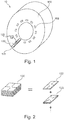
- Fig. 1 schematically shows a MRI scanner 10 according to a preferred embodiment of the invention. It comprises of a field-generating unit 100 (both B0+gradients), which has openings 110 along the longitudinal axis, into which shim rails 111 are inserted. These shim rails 111 have various pockets 120 into which shim irons 130 are placed.
- shim irons 130 in the form of blocks or stacks of slit shim plates 132, 133 as shown in Fig. 2 are placed.
- the amount of shim plates 132 per pocket 120 is determined in several iteration rounds to make the B0 field most homogeneous.
- a part of the so called shimming procedure is done on the customer site to compensate for ferromagnetic building parts and equipment in the vicinity of the MRI scanner 10.
- Fig. 3 shows an enlarged cross-sectional view of a part of the field-generating unit 100. It consists of an outer part of a BO-generating unit 111 (preferably a superconducting coil within a cryostat), into which a gradient-generating unit 113 is mounted.
- the gradient-generating unit 113 consists of a gradient coil 116 which is preferably actively shielded by a shielding coil 114, and a spacer 115 is located between them.
- Fig. 4 shows possible locations for a cylindrically shaped layer 117 into which the shim rails 111 with the shim irons 130 are mounted.
- option A is used in older scanners
- option C is preferably used for the present preferred embodiment of the invention.
- Option C is chosen for its better space usage, allowing larger free-bore diameters (e.g. 70cm) and hence accessibility also to obese patients. This space usage stems from the fact, that the spacer 115 is needed anyhow to separate coils 114 and 116, so this space can be used for the shim-iron layer 117, rather than wasted, as in all the other options.
- the shim irons 130 are placed at the location where the gradient field is maximum.
- the shim irons 130 are mechanically connected to the gradient-generating unit 113, which is prone to vibration, rather than to the BO-generating unit 111 (the inner hull of the cryostat), which is rather static. Therefore, option C in MRI scanners leads to an aggravation of a problem long known, i.e. the heating up of the shim irons and hence the thermal drift of the shimming.
- this problem is addressed by using slit shim plates 132, 133 wherein neighboring shim plates132, 133 comprise such slit patterns which are not congruent to each other.
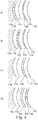
- An example of such slit patterns is shown in Fig. 5 .
- two types of slit patterns for the shim plates 132, 133 is provided.
- shim irons 130 may be stacked in which neighboring shim plates 132, 133 do not comprises congruent slit patterns. In this way, eddy currents in these shim irons 132, 133 are reduced and, hence, heating of the shim irons 130 is reduced.
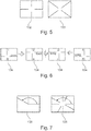
- Shim irons 130 in which neighboring shim plates 132, 133 do not comprises congruent slit patterns may also be stacked with the help of shim plates 134 which all comprise the same asymmetric slit pattern as shown in Fig. 6 .
- shim plate 134 which provides - from the same viewing angle - four different non-congruent slit patterns by turning the shim plate 134 from its back side to its front side and by turning the shim plate 134 by 180° along its normal axis which is indicated by "front” and “back” as well as “1", "2", “3", and "4" on both sides of the shim plate 134.
- Only one type of slitted shim plate has to be manufactured. The desired difference in the shim plates is achieved by rotating the plate around its axis.
- numbering of the shim plates 134 as described before, or color coding of the shim plates 134 may be used so that workflow during shimming, i.e. stacking the shim plates 134 to generate a shim iron which fits the needs, is not affected to much.
- a MR service engineer has to stack the plates so that the numbers 1 ->2 - >3 ->4 ->1 are consecutively readable when stacking the plates.
- the asymmetric " +"- slit pattern used here has the further advantage that an identical slitting pattern repeats at the 5th shim plate 134 instead of the 3rd shim plate 132, 133 as in Fig. 5 further improving the slitting efficiency.
- Fig. 7 overcomes the problem of keeping the right order during stacking.
- the slits of the shim plates 135 are punched with a non repeating pattern.
- the slit pattern is rotated with respect to the shim plate by a certain non-rational angle, like the Golden Angle ratio.
- the Golden Angle is the smaller of the two angles created by sectioning the circumference of a circle according to the golden ratio, i.e. into two arcs such that the ratio of the length of the larger arc to the length of the smaller arc is the same as the ratio of the full circumference to the length of the larger arc.
- the Golden Angel can be approximated in degrees as 137.508°.
- each shim plate is unique, numbering or coding is not required anymore.
- the non-repeating slitting pattern will reduce the eddy-currents significantly.
- its centre can also be slightly moved in order to reduce the size of the finally unslitted region in the centre.
- a further advantage of the proposed non-repeating, simple slitting pattern is, that it can be produced easily.
- the slitting pattern for each plate is simple and the rotation can be performed without difficulty.
Landscapes
- Physics & Mathematics (AREA)
- Condensed Matter Physics & Semiconductors (AREA)
- General Physics & Mathematics (AREA)
- Magnetic Resonance Imaging Apparatus (AREA)
Abstract
The invention relates to a shim iron (130) for use with an magnetic resonance (MR) apparatus (10), wherein the shim iron (130) is comprised of a stack of shim plates (131, 132, 133, 134, 135), wherein at least two of the shim plates (131, 132, 133, 134, 135) comprise slits, the slits forming a respective slit pattern of the slit shim plates (131, 132, 133, 134, 135), and wherein the slit patterns, when viewed from the same viewing direction, are comprised of at least two different slit patterns which may not be brought into congruent coverage with each other. In this way, a shim iron (130) is provided which does not heat up to high temperatures due to eddy currents.
Description
- The invention relates to the field of shim irons for use with a magnetic resonance (MR) apparatus, and in particular to shim irons which are comprised of a stack of shim plates which are slit in order to reduce heating of the shim irons due to eddy currents.
- In nuclear magnetic resonance (NMR) and magnetic resonance imaging (MRI), shimming is used prior to the operation of the magnet to eliminate inhomogeneities in its static magnetic field. Initially, the magnetic field inside an NMR spectrometer or MRI scanner is far from homogeneous compared with an "ideal" field of the device. This is a result of production tolerances and of the environment of the scanner. Iron constructions in walls and floor of the examination room become magnetized and disturb the field of the scanner. The probe and the sample or the patient become slightly magnetized when brought into the strong magnetic field and create additional inhomogeneous fields. The process of correcting for these inhomogeneities is called shimming the magnet, shimming the probe or shimming the sample, depending on the assumed source of the remaining inhomogeneity. Field homogeneity of the order of 1 ppm over a volume of several liters is needed in an MRI scanner. High-resolution NMR spectroscopy demands field homogeneity better than 1 ppb within a volume of a few milliliters.
- In general, there are two types of shimming: active shimming and passive shimming. Active shimming uses coils with adjustable current. Passive shimming involves pieces of steel with suitable magnetic properties, also called shim irons. The shim irons are placed near the permanent or superconducting magnet. They become magnetized and produce their own magnetic field. In both cases, the additional magnetic fields from the coils or shim irons, respectively, add to the overall magnetic field of the superconducting magnet in such a way as to increase the homogeneity of the total field.
- Typically, a MRI scanner comprises a field-generating unit (both B0+gradients), which has openings along the longitudinal axis into which shim rails are inserted. These shim rails have various pockets into which shim irons are placed. In present MRI scanners, shim irons are typically placed at locations where the gradient field is close to maximum. Further, in such a configuration, the shim irons are mechanically connected to the gradient-generating unit which is prone to vibration, rather than to the BO-generating unit (the inner hull of the cryostat), which is rather static. Therefore, the recent deployment of such MRI scanners leads to an aggravation of a problem long known, i.e. the heating of the shim irons and hence the thermal drift of the shimming.
- This means that though by careful passive shimming very good static homogeneity of the main magnetic field may be achieved, there is a disadvantage of this technique in that the shim material is temperature sensitive, and when the bore heats (as it commonly does with gradient-intensive sequences), field shifts may occur. Heating of the shim plates is mainly caused by eddy currents. A time variant magnetic flux (the gradient field) induces currents in the shim plates which heat the shim plates. Hence, changes in temperature will cause the magnetic distribution created by the passive shims to change, with potentially detrimental effects on image quality and geometric accuracy. The implementation of passive shims must therefore proceed only with the awareness that their proper functioning depends on stable temperature conditions.
- Various attempts were therefore presented in patent literature to keep the temperature of the shim irons constant for the time of a imaging scan or imaging sequence, e.g. pre-heating them locally, special cooling directly for the shim irons, or by regulating the cooling on the outflow rather than the inflow temperature. Alternatively, materials or mixture of materials may be used, in which the negative thermal coefficient of the saturation of the magnetization of the iron is counteracted.
- From
US 5,555,251 it is known that two opposite iron core pole pieces of a magnetic resonance medical imager generate a static magnetic field in a patient imaging volume disposed between the pole pieces. Gradient coils are positioned in the face of a pole piece. Thin disc shaped or ring shaped ferromagnetic parts laminated of layers cut favorably from transformer sheet material are attached to the face of the pole piece. Each layer is electrically insulated from adjacent layers and surfaces by enamel or fixing glue. To reduce eddy currents in these layers, narrow, radially oriented slots are cut in these layers before lamination. The slots are oriented in the adjacent layers so as not to coincide resulting in improved conduction of the magnetic flux in the imaging volume during the production of gradient magnetic fields by the gradient coils. - It is an object of the invention to an easy and effective way for shimming a MR apparatus with a shim iron with substantially reduced heating caused by eddy currents induced by gradient fields.
- According to the invention, this object is addressed by the subject matter of the independent claims. Preferred embodiments of the invention are described in the sub claims.
- Therefore, according to the invention, a shim iron for use with a magnetic resonance (MR) apparatus is provided,
wherein the shim iron is comprised of a stack of shim plates,
wherein at least two of the shim plates comprise slits, the slits forming a respective slit pattern of the slit shim plates, and
wherein the slit patterns, when viewed from the same viewing direction, are comprised of at least two different slit patterns which may not be brought into congruent coverage with each other. - According to the invention, is has been found that straight forward slitting works well for relatively small frequencies, however at higher frequencies (> 1000 Hz) slitting even increases the losses. This seems to be due to the effect, that for high frequencies the shim plates cannot be treated in 2D, but rather in 3D. Thus, it has been found that consecutive shim plates should not comprise the same slit pattern, especially not a slit pattern for which slits of consecutive shim plates cover each other.
- Hence, it is an essential idea of the invention to avoid such slit patterns of the different shim plates which, in general, would allow that consecutive shim plates of a stack of shim plates are in congruent coverage. This means that according to the invention it is avoided that the slits of consecutive shim plates of a stack are aligned in the same way. In this way, a shim iron comprised of such shim plates may be assembled in an easy and reliable way avoiding such direct coverage of slits of consecutive/neighboring shim plates.
- Fields generated by induced eddy currents on one shim plate superimpose constructively with that of neighboring (consecutive) plates. This insight has lead to the demand of breaking this constructive superposition. In this respect, the invention proposes to use shim plates with different types of slitting. The basic idea is to have different slitting patterns in every consecutive plate, so that by stacking the plates the slits do not coincide.
- In general the invention allows that only part of the shim plates of the shim iron comprise slits. However, according to a preferred embodiment of the invention all of the shim plates comprise slits. Further, in general, the shim plates could be of different shapes. However, according to a preferred embodiment of the invention, the shim plates all have the same shape, which preferably is a rectangular shape. As set out further below, this allows for correct alignment of the slit patterns of the shim plates in an easy and reliable way when assembling a shim iron. Though rectangular shim plates could have the shape of squares, according to a preferred embodiment of the invention, the s rectangular him plates have sides with different lengths. This makes correct alignment of the shim plates even easier.
- The positive effect of the invention may be achieved with different shapes of the slits themselves. However, according to a preferred embodiment of the invention, the slits all run straight. Though, in general the shim plates could have different thicknesses, according to a preferred embodiment of the invention all shim plates have the same thickness. The shim plates could also be made from different magnetizable materials. However, it is preferred that the shim plates are all made from the same magnetizable material. Preferably, consecutive shim plates are galvanically insulated from each other, preferably by insulation sheets having the same shape as the shim plates.
- There are different ways to implement the invention. According to one preferred alternative all shim plates are slit in the same way, wherein the slit pattern, when viewed from one side of a respective shim plate, is different from the slit pattern when viewed from the other side of the shim plate. In this respect, the slim pattern is preferably asymmetric. Hence, though two shim plates have the same slit pattern, turning of one shim plate by 180° onto its other side yields another slit pattern which may not be brought in congruent coverage with the slit pattern of the other shim plate.
- As an alternative to the solution mentioned above, according to a preferred embodiment of the invention, the slit patterns, independently from the viewing direction, are comprised of at least two different slit patterns which may not be brought into congruent coverage with each other. This means that the slit patterns are always different, no matter to which side a shim plate is turned or from which side it is viewed. With at least two different slit pattern which are shaped in this way a stack of shim plates may be assembled for which the slit patterns of consecutive shim plates are not in congruent coverage with each other.
- In this respect, according to a preferred embodiment of the invention, all slit patterns comprise the same number of straight slits, the straight slits having the same relative angels to each other, wherein the orientation of the slits of the slit pattern of a second shim plate is given by an integer number of non-rational angle rotations, preferably Golden Angle rotations of each slit of the slit pattern of a first shim plate. In geometry, the Golden Angle is the smaller of the two angles created by sectioning the circumference of a circle according to the golden ratio, i.e. into two arcs such that the ratio of the length of the larger arc to the length of the smaller arc is the same as the ratio of the full circumference to the length of the larger arc. The Golden Angel can be approximated in degrees as 137.508°. In this way, it may be achieved in an easy and reliable way that the slit patterns of all shim plates of a shim iron, when viewed from the same viewing direction, are all different from each other.
- The invention further relates to a shim rail with a plurality of pockets, wherein at least one pocket comprises a shim iron as described before.
- The invention also relates to a MRI apparatus with a bore for accommodating a subject to examined and a field-generating unit surrounding the bore, wherein the field-generating unit comprises a plurality of openings which run parallel to the longitudinal axis of the bore and wherein at least one of the plurality of bores comprises a shim rail as described before.
- Furthermore, the invention also relates to a method of shimming a MRI apparatus with at least one shim iron, comprising the following method steps:
- providing at least two shim plates which comprise slits, the slits forming a respective slit pattern of the slit shim plates, wherein the slit patterns, when viewed from the same viewing direction, are comprised of at least two different slit patterns which may not be brought into congruent coverage with each other,
- assembling the at least one shim iron by stacking the at least two shim plates in such a way that the at least two shim plates are not in congruent coverage with each other, and
- mounting the at least one shim iron onto the MRI apparatus for shimming the MRI apparatus.
- Preferably, the method comprises the additional method step of:
- assembling the at least one shim iron by stacking the at least another shim plate onto the at least two shim plates in such a way that consecutive shim plates are not in congruent coverage with each other.
- Finally, the invention also relates to a method of manufacturing a shim plate for a shim iron which is to be used in a MRI apparatus, comprising the following steps:
- providing a first unslit shim plate,
- slitting the first unslit shim plate with a slim pattern which comprises a predetermined number of straight slits, the straight slits having a predetermined relative angels to each other,
- providing a second unslit shim plate,
- slitting the second unslit shim plate with a slim pattern which comprises the same predetermined number of straight slits as the first shim plate, the straight slits having a the same predetermined relative angels to each other as the first shim plate, wherein the orientation of the slits of the slit pattern of the second shim plate is given by an integer number of non-rational angle rotations , preferably Golden Angle rotations, of each slit of the slit pattern of the first shim plate.
- These and other aspects of the invention will be apparent from and elucidated with reference to the embodiments described hereinafter. Such an embodiment does not necessarily represent the full scope of the invention, however, and reference is made therefore to the claims and herein for interpreting the scope of the invention.
- In the drawings:
-
Fig. 1 schematically depicts a MRI scanner according to a preferred embodiment of the invention; -
Fig. 2 . schematically depicts a shim iron in the form of a blocks or stack of slit shim plates according to a preferred embodiment of the invention; -
Fig. 3 shows an enlarged cross-sectional view of a part of the field-generating unit of the MRI scanner according to the preferred embodiment of the invention; -
Fig. 4 schematically depicts possible locations for a cylindrically shaped layer into which the shim rails with the shim irons are mounted according to the preferred embodiment of the invention; -
Fig. 5 schematically depicts shim plates according to a preferred embodiment of the invention; -
Fig. 6 schematically depicts shim plates according to another preferred embodiment of the invention; and -
Fig. 7 schematically depicts shim plates according to still another preferred embodiment of the invention. -
Fig. 1 schematically shows aMRI scanner 10 according to a preferred embodiment of the invention. It comprises of a field-generating unit 100 (both B0+gradients), which hasopenings 110 along the longitudinal axis, into which shim rails 111 are inserted. These shim rails 111 havevarious pockets 120 into which shimirons 130 are placed. - According to the preferred embodiment of the invention, there are more than one hundred
pockets 120 per MR system whereshim irons 130 in the form of blocks or stacks ofslit shim plates Fig. 2 are placed. The amount ofshim plates 132 perpocket 120 is determined in several iteration rounds to make the B0 field most homogeneous. A part of the so called shimming procedure is done on the customer site to compensate for ferromagnetic building parts and equipment in the vicinity of theMRI scanner 10. -
Fig. 3 shows an enlarged cross-sectional view of a part of the field-generatingunit 100. It consists of an outer part of a BO-generating unit 111 (preferably a superconducting coil within a cryostat), into which a gradient-generatingunit 113 is mounted. The gradient-generatingunit 113 consists of agradient coil 116 which is preferably actively shielded by a shieldingcoil 114, and aspacer 115 is located between them. -
Fig. 4 shows possible locations for a cylindrically shapedlayer 117 into which the shim rails 111 with theshim irons 130 are mounted. While option A is used in older scanners, option C is preferably used for the present preferred embodiment of the invention. Option C is chosen for its better space usage, allowing larger free-bore diameters (e.g. 70cm) and hence accessibility also to obese patients. This space usage stems from the fact, that thespacer 115 is needed anyhow toseparate coils iron layer 117, rather than wasted, as in all the other options. Further, in configuration C, theshim irons 130 are placed at the location where the gradient field is maximum. Furthermore, in this configuration, theshim irons 130 are mechanically connected to the gradient-generatingunit 113, which is prone to vibration, rather than to the BO-generating unit 111 (the inner hull of the cryostat), which is rather static. Therefore, option C in MRI scanners leads to an aggravation of a problem long known, i.e. the heating up of the shim irons and hence the thermal drift of the shimming. - According to the preferred embodiment of the invention, this problem is addressed by using
slit shim plates slit shim plates shim plate 132 is covered by a slit of anothershim plate 133. An example of such slit patterns is shown inFig. 5 . Here, two types of slit patterns for theshim plates different shim plates shim irons 130 may be stacked in which neighboringshim plates shim irons shim irons 130 is reduced. - Shim
irons 130 in which neighboringshim plates shim plates 134 which all comprise the same asymmetric slit pattern as shown inFig. 6 . Here, oneshim plate 134 is shown which provides - from the same viewing angle - four different non-congruent slit patterns by turning theshim plate 134 from its back side to its front side and by turning theshim plate 134 by 180° along its normal axis which is indicated by "front" and "back" as well as "1", "2", "3", and "4" on both sides of theshim plate 134. Only one type of slitted shim plate has to be manufactured. The desired difference in the shim plates is achieved by rotating the plate around its axis. - Hence, numbering of the
shim plates 134 as described before, or color coding of theshim plates 134 may be used so that workflow during shimming, i.e. stacking theshim plates 134 to generate a shim iron which fits the needs, is not affected to much. In the example ofFig. 6 , a MR service engineer has to stack the plates so that the numbers 1 ->2 - >3 ->4 ->1 are consecutively readable when stacking the plates. The asymmetric " +"- slit pattern used here has the further advantage that an identical slitting pattern repeats at the5th shim plate 134 instead of the3rd shim plate Fig. 5 further improving the slitting efficiency. - The preferred embodiment of
Fig. 7 overcomes the problem of keeping the right order during stacking. Here, the slits of theshim plates 135 are punched with a non repeating pattern. The slit pattern is rotated with respect to the shim plate by a certain non-rational angle, like the Golden Angle ratio. In geometry, the Golden Angle is the smaller of the two angles created by sectioning the circumference of a circle according to the golden ratio, i.e. into two arcs such that the ratio of the length of the larger arc to the length of the smaller arc is the same as the ratio of the full circumference to the length of the larger arc. The Golden Angel can be approximated in degrees as 137.508°. This achieves that each shim plate is unique, numbering or coding is not required anymore. Thus the shimming procedure can be performed as it is done today, but the non-repeating slitting pattern will reduce the eddy-currents significantly. In addition to rotating the slitting pattern, its centre can also be slightly moved in order to reduce the size of the finally unslitted region in the centre. A further advantage of the proposed non-repeating, simple slitting pattern is, that it can be produced easily. The slitting pattern for each plate is simple and the rotation can be performed without difficulty. - While the invention has been illustrated and described in detail in the drawings and foregoing description, such illustration and description are to be considered illustrative or exemplary and not restrictive; the invention is not limited to the disclosed embodiments. Other variations to the disclosed embodiments can be understood and effected by those skilled in the art in practicing the claimed invention, from a study of the drawings, the disclosure, and the appended claims. In the claims, the word "comprising" does not exclude other elements or steps, and the indefinite article "a" or "an" does not exclude a plurality. The mere fact that certain measures are recited in mutually different dependent claims does not indicate that a combination of these measures cannot be used to advantage. Any reference signs in the claims should not be construed as limiting the scope. Further, for the sake of clearness, not all elements in the drawings may have been supplied with reference signs.
-
- MRI scanner
- 10
- field-generating unit
- 100
- openings
- 110
- shim rails
- 111
- air gap between cryostat and gradient coi
- 112
- gradient-generating unit
- 113
- shielding coil
- 114
- spacer
- 115
- gradient coil
- 116
- cylindrically shaped layer
- 117
- BO-generating unit
- 118
- pockets
- 120
- shim irons
- 130
- shim plate
- 131
- shim plate
- 132
- shim plate
- 133
- shim plate
- 134
- shim plate
- 135
Claims (12)
- Shim iron (130) for use with a magnetic resonance (MR) apparatus (10),
wherein the shim iron (130) is comprised of a stack of shim plates (131, 132, 133, 134, 135),
wherein at least two of the shim plates (131, 132, 133, 134, 135) comprise slits, the slits forming a respective slit pattern of the slit shim plates (131, 132, 133, 134, 135), and
wherein the slit patterns, when viewed from the same viewing direction, are comprised of at least two different slit patterns which may not be brought into congruent coverage with each other. - Shim iron (130) according to claim 1, wherein the shim plates all (131, 132, 133, 134, 135) have the same rectangular shape and wherein the shim plates (131, 132, 133, 134, 135) have two sides with different lengths.
- Shim iron (130) according to any of the preceding claims, wherein all shim plates (131, 132, 133, 134, 135) are slit in the same way, wherein the slit pattern, when viewed from one side of a respective shim plate (131, 132, 133, 134, 135), is different from the slit pattern when viewed from the other of the shim plate (131, 132, 133, 134, 135).
- Shim iron (130) according to claim 3, wherein the slim pattern is asymmetric.
- Shim iron (130) according to claims 1 or 2, wherein the slit patterns, independently from the viewing direction, are comprised of at least two different slit patterns which may not be brought into congruent coverage with each other.
- Shim iron (130) according to claim 5, wherein all slit patterns comprise the same number of straight slits, the straight slits having the same relative angels to each other, wherein the orientation of the slits of the slit pattern of a second shim plate (131, 132, 133, 134, 135) is given by an integer number of non-rational rotations of each slit of the slit pattern of a first shim plate (131, 132, 133, 134, 135).
- Shim iron (130) according to claim 5 or 6, wherein the slit patterns, when viewed from the same viewing direction, are all different from each other.
- Shim rail (11) with a plurality of pockets (120), wherein at least one pocket (120) comprises a shim iron (130) according to any of the preceding claims.
- MRI apparatus (10) with a bore for accommodating a subject to examined and a field-generating unit (100) surrounding the bore, wherein the field-generating unit (100) comprises a plurality of openings (110) which run parallel to the longitudinal axis of the bore and wherein at least one of the plurality of bores (100) comprises a shim rail (111) according to claim 8.
- Method of shimming an MRI apparatus (10) with at least one shim iron (130), comprising the following method steps:
providing at least two of the shim plates (131, 132, 133, 134, 135) which comprise slits, the slits forming a respective slit pattern of the slit shim plates (131, 132, 133, 134, 135), wherein the slit patterns, when viewed from the same viewing direction, are comprised of at least two different slit patterns which may not be brought into congruent coverage with each other,- assembling the at least one shim iron (130) by stacking the at least two shim plates (131, 132, 133, 134, 135) in such a way that the at least two shim plates (131, 132, 133, 134, 135) are not in congruent coverage with each other, and- mounting the at least one shim iron (130) into the MRI apparatus (10) for shimming the MRI apparatus (10). - Method according to claim 10, comprising the additional method step of:- assembling the at least one shim iron (130) by stacking the at least another shim plate (131, 132, 133, 134, 135) onto the at least two shim plates (131, 132, 133, 134, 135) in such a way that consecutive shim plates (131, 132, 133, 134, 135) are not in congruent coverage with each other.
- Method of manufacturing a shim plate (131, 132, 133, 134, 135) for a shim iron (130) which is to be used in a MRI apparatus (10), comprising the following steps:- providing a first unslit shim plate,- slitting the first unslit shim plate with a slit pattern which comprises a predetermined number of straight slits, the straight slits having a predetermined relative angels to each other,- providing a second unslit shim plate,- slitting the second unslit shim plate with a slim pattern which comprises the same predetermined number of straight slits as the first shim plate (131, 132, 133, 134, 135), the straight slits having a the same predetermined relative angels to each other as the first shim plate (131, 132, 133, 134, 135), wherein the orientation of the slits of the slit pattern of the second shim plate (131, 132, 133, 134, 135) is given by an integer number of non-rational rotations of each slit of the slit pattern of the first shim plate (131, 132, 133, 134, 135).
Priority Applications (9)
| Application Number | Priority Date | Filing Date | Title |
|---|---|---|---|
| EP18166915.1A EP3553547A1 (en) | 2018-04-12 | 2018-04-12 | Shim irons for a magnetic resonance apparatus |
| BR112020020789-6A BR112020020789A2 (en) | 2018-04-12 | 2019-04-02 | FERROMAGNETIC WEDGE FOR USE WITH A MAGNETIC RESONANCE APPARATUS, WEDGE RAIL WITH A PLURALITY OF POCKETS, MRI MACHINE WITH A TUNNEL TO ACCOMMODATE AN INDIVIDUAL TO BE EXAMINED AND A FIELD GENERATING UNIT circling the TUNNEL, SHIMMING METHOD IN AN MRI DEVICE WITH AT LEAST ONE FERROMAGNETIC WEDGE, AND METHOD OF MANUFACTURING A WEDGE PLATE FOR A FERROMAGNETIC WEDGE TO BE USED AND AN MRI DEVICE |
| US17/046,785 US11269033B2 (en) | 2018-04-12 | 2019-04-02 | Shim irons for a magnetic resonance apparatus |
| CN201980031451.2A CN112105941B (en) | 2018-04-12 | 2019-04-02 | Shim iron for magnetic resonance equipment |
| RU2020137021A RU2759083C1 (en) | 2018-04-12 | 2019-04-02 | Shimming iron elements for a magnetic resonance apparatus |
| EP19713520.5A EP3775955B1 (en) | 2018-04-12 | 2019-04-02 | Shim irons for a magnetic resonance apparatus |
| PCT/EP2019/058296 WO2019197221A1 (en) | 2018-04-12 | 2019-04-02 | Shim irons for a magnetic resonance apparatus |
| JP2020555103A JP7104171B2 (en) | 2018-04-12 | 2019-04-02 | Sim iron for magnetic resonance equipment |
| JP2022067352A JP7407857B2 (en) | 2018-04-12 | 2022-04-15 | Shim iron for magnetic resonance equipment |
Applications Claiming Priority (1)
| Application Number | Priority Date | Filing Date | Title |
|---|---|---|---|
| EP18166915.1A EP3553547A1 (en) | 2018-04-12 | 2018-04-12 | Shim irons for a magnetic resonance apparatus |
Publications (1)
| Publication Number | Publication Date |
|---|---|
| EP3553547A1 true EP3553547A1 (en) | 2019-10-16 |
Family
ID=61971993
Family Applications (2)
| Application Number | Title | Priority Date | Filing Date |
|---|---|---|---|
| EP18166915.1A Withdrawn EP3553547A1 (en) | 2018-04-12 | 2018-04-12 | Shim irons for a magnetic resonance apparatus |
| EP19713520.5A Active EP3775955B1 (en) | 2018-04-12 | 2019-04-02 | Shim irons for a magnetic resonance apparatus |
Family Applications After (1)
| Application Number | Title | Priority Date | Filing Date |
|---|---|---|---|
| EP19713520.5A Active EP3775955B1 (en) | 2018-04-12 | 2019-04-02 | Shim irons for a magnetic resonance apparatus |
Country Status (7)
| Country | Link |
|---|---|
| US (1) | US11269033B2 (en) |
| EP (2) | EP3553547A1 (en) |
| JP (2) | JP7104171B2 (en) |
| CN (1) | CN112105941B (en) |
| BR (1) | BR112020020789A2 (en) |
| RU (1) | RU2759083C1 (en) |
| WO (1) | WO2019197221A1 (en) |
Families Citing this family (2)
| Publication number | Priority date | Publication date | Assignee | Title |
|---|---|---|---|---|
| EP3839542A1 (en) * | 2019-12-16 | 2021-06-23 | Koninklijke Philips N.V. | Optimized orientation of shim elements in an mri system |
| EP4394422A1 (en) * | 2022-12-28 | 2024-07-03 | Siemens Healthineers AG | Shim tray for a gradient coil unit of an mr system |
Citations (4)
| Publication number | Priority date | Publication date | Assignee | Title |
|---|---|---|---|---|
| EP0710851A1 (en) * | 1994-11-04 | 1996-05-08 | Picker International, Inc. | Magnetic resonance apparatus |
| US5555251A (en) | 1993-06-08 | 1996-09-10 | Picker Nordstar Inc. | Arrangement to minimize eddy currents in MR imagers |
| JPH09238917A (en) * | 1996-03-11 | 1997-09-16 | Toshiba Corp | Coil assembly for magnetic resonance diagnosis |
| JP2015211766A (en) * | 2014-05-02 | 2015-11-26 | 株式会社東芝 | Magnetic resonance imaging apparatus and gradient coil |
Family Cites Families (31)
| Publication number | Priority date | Publication date | Assignee | Title |
|---|---|---|---|---|
| JPH05329128A (en) | 1992-05-29 | 1993-12-14 | Mitsubishi Electric Corp | Magnetic field correction device |
| CN1248895A (en) * | 1997-12-26 | 2000-03-29 | 住友特殊金属株式会社 | MRI magnetic field generator |
| US6150819A (en) | 1998-11-24 | 2000-11-21 | General Electric Company | Laminate tiles for an MRI system and method and apparatus for manufacturing the laminate tiles |
| WO2000054069A1 (en) | 1999-03-10 | 2000-09-14 | Koninklijke Philips Electronics N.V. | Method of and device for the compensation of variations of the main magnetic field during magnetic resonance imaging |
| DE10114319C2 (en) * | 2001-03-23 | 2003-02-13 | Siemens Ag | Shim device for a magnetic resonance device |
| JP3878434B2 (en) * | 2001-05-10 | 2007-02-07 | ジーイー・メディカル・システムズ・グローバル・テクノロジー・カンパニー・エルエルシー | Coil structure for magnetic resonance imaging and magnetic resonance imaging apparatus |
| DE10133655B4 (en) | 2001-07-11 | 2004-02-26 | Siemens Ag | Magnetic resonance tomography device with improved spatial and temporal stabilization of the homogeneity of the basic magnetic field |
| JP2003203813A (en) * | 2001-08-29 | 2003-07-18 | Matsushita Electric Ind Co Ltd | Magnetic element, method of manufacturing the same, and power supply module having the same |
| US6627003B2 (en) | 2001-10-24 | 2003-09-30 | Ge Medical Systems Global Technology Company, Llc | NMR shim forming method |
| DE10219769B3 (en) | 2002-05-02 | 2004-01-22 | Siemens Ag | Magnetic resonance device and carrier device that can be equipped with shim elements |
| US6778054B1 (en) | 2003-10-03 | 2004-08-17 | General Electric Company | Methods and apparatus for passive shimming of magnets |
| US6906606B2 (en) | 2003-10-10 | 2005-06-14 | General Electric Company | Magnetic materials, passive shims and magnetic resonance imaging systems |
| DE102005020378B4 (en) | 2005-05-02 | 2010-01-07 | Siemens Ag | Graded-coil magnetic resonance device with integrated passive shim devices |
| US7741847B2 (en) | 2006-10-13 | 2010-06-22 | Kabushiki Kaisha Toshiba | Magnetic resonance apparatus with temperature controlled magnet shim pieces |
| RU2459215C2 (en) * | 2007-04-04 | 2012-08-20 | Конинклейке Филипс Электроникс Н.В. | Split gradient coil and hybrid pet/mr visualisation system that applies it |
| JP2009200174A (en) * | 2008-02-20 | 2009-09-03 | Panasonic Electric Works Co Ltd | Non-contact power transmission apparatus |
| GB0803358D0 (en) | 2008-02-25 | 2008-04-02 | Siemens Magnet Technology Ltd | Method and apparatus for shimming a magnet |
| JP2010269136A (en) | 2009-04-23 | 2010-12-02 | Toshiba Corp | Magnetic resonance imaging equipment |
| JP5349177B2 (en) * | 2009-07-09 | 2013-11-20 | 株式会社東芝 | Magnetic resonance imaging system |
| IT1397713B1 (en) | 2010-01-22 | 2013-01-24 | Esaote Spa | MACHINE FOR NUCLEAR MAGNETIC RESONANCE WITH MEANS FOR THE CORRECTION OF THE HOMOGENITY OF THE MAGNETIC FIELD. |
| US8604793B2 (en) | 2010-10-21 | 2013-12-10 | General Electric Company | Superconducting magnet having cold iron shimming capability |
| RU2592039C2 (en) * | 2010-12-02 | 2016-07-20 | Конинклейке Филипс Электроникс Н.В. | Formation of magnetic resonance images using multiple-point dixon method |
| CN102360691B (en) * | 2011-06-24 | 2013-03-13 | 中国科学院电工研究所 | Open-type nuclear magnetic resonance magnet system with iron hoop structure |
| KR101424552B1 (en) | 2012-09-05 | 2014-07-31 | 삼성전자 주식회사 | Magnetic resonance imaging device and manufacturing method thereof |
| EP3073915A4 (en) * | 2014-01-17 | 2017-08-16 | Arterys Inc. | Apparatus, methods and articles for four dimensional (4d) flow magnetic resonance imaging |
| JP2015208427A (en) | 2014-04-25 | 2015-11-24 | 株式会社日立メディコ | Magnetic resonance imaging system |
| AU2015311749B2 (en) * | 2014-09-05 | 2018-06-21 | Hyperfine Operations, Inc. | Ferromagnetic augmentation for magnetic resonance imaging |
| JP6462292B2 (en) * | 2014-09-26 | 2019-01-30 | キヤノンメディカルシステムズ株式会社 | Magnetic resonance imaging system |
| JP6368625B2 (en) * | 2014-11-18 | 2018-08-01 | 株式会社日立製作所 | Magnetic resonance imaging system |
| JP2016116804A (en) | 2014-12-24 | 2016-06-30 | 株式会社日立製作所 | Magnetic resonance imaging apparatus |
| US11333727B2 (en) * | 2019-12-10 | 2022-05-17 | Hyperfine Operations, Inc. | Ferromagnetic frame for magnetic resonance imaging |
-
2018
- 2018-04-12 EP EP18166915.1A patent/EP3553547A1/en not_active Withdrawn
-
2019
- 2019-04-02 US US17/046,785 patent/US11269033B2/en active Active
- 2019-04-02 EP EP19713520.5A patent/EP3775955B1/en active Active
- 2019-04-02 WO PCT/EP2019/058296 patent/WO2019197221A1/en not_active Ceased
- 2019-04-02 JP JP2020555103A patent/JP7104171B2/en active Active
- 2019-04-02 BR BR112020020789-6A patent/BR112020020789A2/en not_active Application Discontinuation
- 2019-04-02 CN CN201980031451.2A patent/CN112105941B/en active Active
- 2019-04-02 RU RU2020137021A patent/RU2759083C1/en active
-
2022
- 2022-04-15 JP JP2022067352A patent/JP7407857B2/en active Active
Patent Citations (4)
| Publication number | Priority date | Publication date | Assignee | Title |
|---|---|---|---|---|
| US5555251A (en) | 1993-06-08 | 1996-09-10 | Picker Nordstar Inc. | Arrangement to minimize eddy currents in MR imagers |
| EP0710851A1 (en) * | 1994-11-04 | 1996-05-08 | Picker International, Inc. | Magnetic resonance apparatus |
| JPH09238917A (en) * | 1996-03-11 | 1997-09-16 | Toshiba Corp | Coil assembly for magnetic resonance diagnosis |
| JP2015211766A (en) * | 2014-05-02 | 2015-11-26 | 株式会社東芝 | Magnetic resonance imaging apparatus and gradient coil |
Also Published As
| Publication number | Publication date |
|---|---|
| JP7407857B2 (en) | 2024-01-04 |
| BR112020020789A2 (en) | 2021-01-12 |
| US20210181280A1 (en) | 2021-06-17 |
| CN112105941A (en) | 2020-12-18 |
| WO2019197221A1 (en) | 2019-10-17 |
| JP2022109935A (en) | 2022-07-28 |
| EP3775955A1 (en) | 2021-02-17 |
| RU2759083C1 (en) | 2021-11-09 |
| CN112105941B (en) | 2025-01-14 |
| JP7104171B2 (en) | 2022-07-20 |
| JP2021520869A (en) | 2021-08-26 |
| EP3775955B1 (en) | 2021-08-11 |
| US11269033B2 (en) | 2022-03-08 |
Similar Documents
| Publication | Publication Date | Title |
|---|---|---|
| JP5894601B2 (en) | Gradient magnetic field coil apparatus and magnetic resonance imaging apparatus | |
| US4829252A (en) | MRI system with open access to patient image volume | |
| US12553968B2 (en) | Ferromagnetic frame for magnetic resonance imaging | |
| EP4553527A2 (en) | Ferromagnetic augmentation for magnetic resonance imaging | |
| EP1593342B1 (en) | Magnetic field-producing device | |
| US5680046A (en) | Double-sided RF shield for RF coil contained within gradient coils used in high speed NMR imaging | |
| EP0896228A1 (en) | Self-shielded gradient coil assembly and method of manufacturing the same | |
| KR100362042B1 (en) | Magnetic field generating device for mri | |
| CN103675734A (en) | Warm bore cylinder assembly | |
| JP7407857B2 (en) | Shim iron for magnetic resonance equipment | |
| EP3839542A1 (en) | Optimized orientation of shim elements in an mri system | |
| JP2008000324A (en) | Gradient magnetic field coil apparatus for nuclear magnetic resonance imaging system | |
| JP7265561B2 (en) | Gradient shield coil for MRI equipment | |
| JP2007505665A (en) | Magnetic gradient winding system with circular solenoid coil |
Legal Events
| Date | Code | Title | Description |
|---|---|---|---|
| PUAI | Public reference made under article 153(3) epc to a published international application that has entered the european phase |
Free format text: ORIGINAL CODE: 0009012 |
|
| AK | Designated contracting states |
Kind code of ref document: A1 Designated state(s): AL AT BE BG CH CY CZ DE DK EE ES FI FR GB GR HR HU IE IS IT LI LT LU LV MC MK MT NL NO PL PT RO RS SE SI SK SM TR |
|
| AX | Request for extension of the european patent |
Extension state: BA ME |
|
| RAP1 | Party data changed (applicant data changed or rights of an application transferred) |
Owner name: KONINKLIJKE PHILIPS N.V. |
|
| STAA | Information on the status of an ep patent application or granted ep patent |
Free format text: STATUS: THE APPLICATION IS DEEMED TO BE WITHDRAWN |
|
| 18D | Application deemed to be withdrawn |
Effective date: 20200603 |