KR20170036205A - Haptic Simulating Device - Google Patents
Haptic Simulating Device Download PDFInfo
- Publication number
- KR20170036205A KR20170036205A KR1020150135092A KR20150135092A KR20170036205A KR 20170036205 A KR20170036205 A KR 20170036205A KR 1020150135092 A KR1020150135092 A KR 1020150135092A KR 20150135092 A KR20150135092 A KR 20150135092A KR 20170036205 A KR20170036205 A KR 20170036205A
- Authority
- KR
- South Korea
- Prior art keywords
- rotary
- plate
- support
- rotary wheel
- wheel support
- Prior art date
Links
Images


Classifications
-
- A—HUMAN NECESSITIES
- A63—SPORTS; GAMES; AMUSEMENTS
- A63B—APPARATUS FOR PHYSICAL TRAINING, GYMNASTICS, SWIMMING, CLIMBING, OR FENCING; BALL GAMES; TRAINING EQUIPMENT
- A63B22/00—Exercising apparatus specially adapted for conditioning the cardio-vascular system, for training agility or co-ordination of movements
- A63B22/06—Exercising apparatus specially adapted for conditioning the cardio-vascular system, for training agility or co-ordination of movements with support elements performing a rotating cycling movement, i.e. a closed path movement
-
- A—HUMAN NECESSITIES
- A63—SPORTS; GAMES; AMUSEMENTS
- A63F—CARD, BOARD, OR ROULETTE GAMES; INDOOR GAMES USING SMALL MOVING PLAYING BODIES; VIDEO GAMES; GAMES NOT OTHERWISE PROVIDED FOR
- A63F13/00—Video games, i.e. games using an electronically generated display having two or more dimensions
- A63F13/20—Input arrangements for video game devices
- A63F13/21—Input arrangements for video game devices characterised by their sensors, purposes or types
-
- A—HUMAN NECESSITIES
- A63—SPORTS; GAMES; AMUSEMENTS
- A63F—CARD, BOARD, OR ROULETTE GAMES; INDOOR GAMES USING SMALL MOVING PLAYING BODIES; VIDEO GAMES; GAMES NOT OTHERWISE PROVIDED FOR
- A63F13/00—Video games, i.e. games using an electronically generated display having two or more dimensions
- A63F13/20—Input arrangements for video game devices
- A63F13/23—Input arrangements for video game devices for interfacing with the game device, e.g. specific interfaces between game controller and console
-
- A—HUMAN NECESSITIES
- A63—SPORTS; GAMES; AMUSEMENTS
- A63F—CARD, BOARD, OR ROULETTE GAMES; INDOOR GAMES USING SMALL MOVING PLAYING BODIES; VIDEO GAMES; GAMES NOT OTHERWISE PROVIDED FOR
- A63F13/00—Video games, i.e. games using an electronically generated display having two or more dimensions
- A63F13/80—Special adaptations for executing a specific game genre or game mode
- A63F13/803—Driving vehicles or craft, e.g. cars, airplanes, ships, robots or tanks
Abstract
(Haptic Simulating Device)
The present invention relates to a virtual reality game using a toy car, a racing sporting goods, a game using a computer or a smart phone, or a head mount display, and relates to a slip occurring during rotation on a curve track, Wherein the controller is configured to sense a slip friction noise and a trembling phenomenon accompanied by a simulator device that realizes an operational state that causes a secondary rotation by the hands and ears.

Description
It is insufficient to feel the actual feeling by simply providing the function of the game simulator device applied to the general game machine or the exercise machine by rotating the game machine in the left and right direction or by displacing the position in the up and down direction or by providing the vibration function by the vibration device. In order to realize a real feeling in a toy car or a racing game, vibration or slip during rotation or vibration due to frictional force must be transmitted through a steering wheel to cause various curved tracks such as actual driving or racing during play or game The present invention relates to a device capable of adding a feeling of riding comfort and operation feeling that can realize a new concept of tactile feedback function capable of realizing action and feeling.
Most of the conventional simulator apparatuses are manufactured for the purpose of implementing a specific operation, and thus they have been inadequate for the user to have constant interest in use. For example. If you simply click on the gaming mouse during the game, repeat the monotonous movements during your workouts, or you do not feel real, you will lose interest over time and stop using it.
In order to solve such a disadvantage, various simulator devices have been devised and invented in recent years. Especially, in recent years, as games or contents using virtual reality have been developed, corresponding hardware and peripheral devices have become more realistic.
The simulator system developed so far has not been able to realize the same operation as the slip according to the change of operation when the user turns the corner of the actual driving course.
When the present invention is applied to a simulator device for a game for a virtual reality, a virtual environment change in a 360 ° direction is performed by a head mount display connected to a computer or a smart phone, By displaying the visual change, the user can double the immersion to feel the virtual situation as it is.
The Korean Utility Model Registration No. 20-0184370 proposes a riding exercise apparatus for bicycling connected to a game machine. However, due to the elasticity of the reciprocating left and right handles and the rotating pedal and spring, It is made up of a saddle that moves, so that there is no movement in the running of a real bicycle.
Also, in the Korean Utility Model Registration No. 20-0237973, a 'cycle machine' has been proposed similarly, but there are only three rollers that contact the bicycle wheel so that the bicycle can be taken indoors, The structure and the system of the simulator device according to the present invention can be said to be a plate. That is, the apparatus of the present invention is a big difference in that it is installed in a fitness apparatus such as an indoor cycle or built in a game controller, and causes the rotating wheel to generate a frictional force and to cause a rotational force and a slip.
The present invention can be applied to a toy car or a controller for a racing game. In the conventional patents related thereto, Korean Patent No. 10-2005-0113932 " Game machine including handle function " has been proposed. -2008-0039986 'Multi-purpose motion recognition controller' have been proposed. All of these are confined to obtaining a two-dimensional haptic effect, and Korean Patent No. 10-2009-0122023 'Game simulator' is a system for implementing rotational motion by friction force of motion although a three-dimensional haptic effect can be obtained And is configured to be completely different.
In the conventional invention or the proposal, which has been compared with the patent matters, it is difficult to solve the problem by generating the feeling of the slip effect simultaneously with the rotational force by the tilting motion in the left and right directions.
In order to overcome the above-mentioned limited and limitative system of the prior art and to meet the requirements of the haptic stimulator simulator device having an exciting interest such as 'Thrill Motion' from the market, And second, one of the left and right rotating plates of the left and right should be rotated in the opposite directions. Third, the rotating wheels of the rotating wheels, which are brought into contact with each other at the upper end of the rotating plate, And fourth, the rotary wheel should be rotated while being compressed only when the support is inclined to the left and right, and fifth, the rotary plate should be configured to rotate only at a predetermined angle. Sixth, the feeling of rotation, the vibration of the rotating plate, and the slip by the frictional force generated in the rotating plate must be detected through the handle. Finally, these sensible movements must occur repeatedly and regularly each time the support is tilted to the left or to the right.
Various techniques have been attempted to enhance the body sensibility in order to increase the degree of immersion of the exercise or game or play.
In order to achieve the above object, the apparatus of the present invention is designed to generate a rotational force even if the support stand or the handle is tilted to the left and right without operating the handle to rotate left and right, And the slip is generated when the rotation axis is different from that of the rotation axis, and the vibration is generated in the rotation or slipping, thereby maximizing the bodily sensation effect. Driving sources can be variously adopted. In other words, it can be equipped with an electric motor or a manual pedal to generate torque, and a wheel can be mounted to obtain rotational force through the wheel when moving. A spring or rubber may be used as an elastic material for tilting the support to the left or right. A projection for generating vibration may be embossed on the rotary plate or a material having a large frictional force may be attached to the upper end of the rotary plate. The device of the present invention can be manufactured in a small size to be embedded in a controller of a game or can be manufactured in a large size to be mounted at the bottom of a handle of a bicycle cycle. The material can be processed in a light plastic material, . The pressing wheel for forming the instantaneous frictional force on the rotating plate can be configured in various forms. In other words, the wheel itself can be fixed with springs or rubber, or it can be replaced with a stopper (STOPPER) made of durable and abrasion resistant material like ceramics instead of wheels.
The shape of the handle mounted on the present invention can be variously shaped to achieve various purposes. The shape of the handle of the bicycle can be fixed to the support so that the handle itself can be tilted to the left and right, and the support itself can be fixed to the body so that the body can be tilted left and right. In some cases, a handle in the form of a wheel may be fixedly attached to the support.
The appearance of the product to which the apparatus of the present invention is attached may be various forms such as an automobile, a bicycle, a skateboard, a ski board, a surfboard, a Bob sledge, a water boat, a computer mouse and the like.
As the structure or system of the power transmission apparatus according to the apparatus of the present invention, a pulley capable of transmitting power by ring-pinion gears or belts of bevel gears as shown in the drawings may be used.
The control device according to the present invention may be equipped with various sensors and may have a built-in transmission / reception device, or may not be provided with a separate electric control device for the purpose of merely a simple haptic effect.
Various exercise apparatuses (e.g., a cycle, a stepper machine, a skateboard, and a surfboard) equipped with the sensory simulator apparatus according to the present invention similarly reproduce the motion of the curve road in the outdoors, If you increase the interest of the exercise while operating it in conjunction with the game, you can increase the effect of the game as the game is fun, and you will not get tired of repeatedly using it.
It is advantageous that the structure is simple and the manufacturing cost is low because the haptic effect can be obtained without using an external electric power source. It can be a beneficial invention device for the elderly who need a proper exercise as well as a young adolescent because it gains healthy and healthy exercise effect while increasing immersion.
In addition, when the apparatus of the present invention is installed in a game controller, it can be adopted as an alternative to solve social problems such as social violence or firearm accident by inducing a game from a game of abusive addictive game, . Further, when the apparatus of the present invention is modularized in size, it can be supplied at low cost as a general game controller.
In addition, it is expected that the game for virtual reality will be popularized gradually, and since it is required to be connected with hardware having a higher sense of sensitivity due to the characteristics of such a game, it will also be used as a peripheral device of games and contents.
Finally, the haptic simulator device of the present invention can be used as an accessory to various toys and athletic equipment. In addition to the basic functions such as front and rear movement of the product by turning the wheels and changing the direction by the handle, the rotation sensitivity and slip, vibration, and operating sound that can be felt when the product is rotated while tilting the product for left and right rotation It can be produced as a haptic device similar to the actual product and can be used as a differentiated product from the previous product.
By providing the user who uses the toy product or the exercise device with the real feeling through the driving / operating hand, it can not only enhance the satisfaction as the play device but also popularize the product.
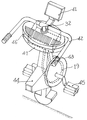
1 shows a bicycle cycle equipped with a built-in sensible-feeling simulator device according to the present invention. Fig.
2A is a total exploded view for explaining the overall component configuration of a haptic simulator device composed of two
FIG. 2B is a graph showing the total exploded view for explaining the overall component configuration of the haptic simulator device composed of one rotary plate 16 '
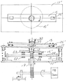
3A is an overall sectional view for explaining the parts configuration of a haptic simulator device composed of two
FIG. 3B is an overall sectional view for explaining a component configuration of a bodily-sensible simulator device composed of one rotary plate 16 'according to the present invention. FIG.
FIG. 4 is a plan view and a cross-sectional view for explaining the rotation operation of the
5A is a plan view and a sectional view for explaining the rotation operation of the
5B is a plan view and a cross-sectional view for explaining the rotation operation of the
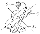
6A is an explanatory diagram of the rotation angle of the
6B is a perspective view for explaining the operation state of the sensible-feeling simulator device according to the present invention with respect to the rotational angle of the
7 is a perspective view and a cross-sectional view for explaining a
8 is an exploded perspective view of a bicycle cycle equipped with the haptic-
9 is a perspective view showing an application example of a game controller mouse equipped with the haptic simulator device according to the present invention.
10 is a perspective view showing an example of a toy vehicle incorporating the haptic simulator device according to the present invention as an application example
DETAILED DESCRIPTION OF THE PREFERRED EMBODIMENTS Hereinafter, a haptic-type simulator device according to the present invention will be described with reference to the accompanying drawings.
First, it should be noted that the same components or parts among the drawings are denoted by the same reference numerals as possible. In the following description of the present invention, a detailed description of known functions and configurations incorporated herein will be omitted so as to avoid obscuring the subject matter of the present invention.
FIG. 1 is a perspective view showing an outer appearance of a front portion of a bicycle cycle equipped with a built-in bodily sensation simulator device according to the present invention. In the upper part of the
FIG. 2A is a total exploded view of a bodily-sensible simulator apparatus constituted by two
Two rotating
The rotating
Fig. 2b shows one rotating plate 16 'according to the present invention. And the assembling relationship of the entire constituent parts is shown. 2A, on the upper surface of the
In the
In the
FIG. 3A shows the assembled state of the components of the bodily-feeling simulator device constituted by one rotating plate 16 'according to the present invention, and FIG. And the assembly correlation and state of the components shown in FIG. 2B are clearly shown. The above-described
Hereinafter, the components and accessories of the sensory stimulation apparatus according to the present invention will be described, and the functions and operations related to the components will be described in detail with reference to the following drawings.
First, FIG. 4 shows the operation of the haptic simulator device according to the present invention with respect to the
6A. [0042] The above-mentioned
Then, when a force is applied to the right side of the rotary
5B shows an operating state of the rotary plate 16 'when the
8 is an exploded perspective view showing the haptic simulator device according to the present invention mounted on a bicycle cycle. Figs. 9 and 10 show an application example different from Fig. 8 in an entire exploded perspective view. And is mounted and mounted in a toy vehicle.
As described above, the haptic-type simulator device according to the present invention can be applied to a variety of applications as needed or to increase the degree of haptic sensation as it is practically used. Will become more apparent in light of such implementation and application of the invention.
It is to be understood that both the foregoing description and examples are to be construed as merely illustrative, and that the true scope and spirit of the invention will be defined by the appended claims, May be made within the scope of the claims.
11: base plate 12: frame fixing plate
13: rotation
15: a
17: spring A 18: brake
19: Belt 20: Casters
21: ring gear 22: pinion gear
23: Spur gear 24:
25,25 ':
27: Bearing A 28: Bearing B
29: Bearing C 30:
31: projection 32: handle coupling
33: spring B 42: handle
41: display 44: frame
43: handle
45: Pedal 48: Electric motor
47, 47 ', 47 ": lower body 50:
49: direction changing belt 52: friction material A
51: support standper
53: Friction material B
Claims (5)
The ring gear 21 and the pinion gear 22, which are meshed with each other at both ends of the rotary shaft 24 so that the two rotary plates 16 mounted on the rotary plate support 25 are rotated in opposite directions, A bodily-sensible simulator device
When the rotary wheel support 15 is inclined in the left and right directions, the friction member A (refer to FIG. 1) on the lower surface of one rotary plate 16 ', which is mounted to rotate about the rotary plate support 25' 52) is mounted on the rotary shaft (24) and is rotated by the contact with the rotating friction material (B) (53) so that the rotary wheel support (15)
The caster 20 of the rotary wheel 26 is rotated from the upper surface of the rotary plate 16 by the rotational force of the rotary plate 16 when the rotary wheel support 15 is inclined in the left and right directions, Characterized in that a brake (18) is provided on the rotary wheel (26) for stopping rolling motion of the rotary wheel
Characterized in that a projection (31) is provided on the upper surface of the rotary plate (16)
Priority Applications (2)
| Application Number | Priority Date | Filing Date | Title |
|---|---|---|---|
| KR1020150135092A KR101758045B1 (en) | 2015-09-24 | 2015-09-24 | Haptic Simulating Device |
| PCT/KR2015/012803 WO2017051985A1 (en) | 2015-09-24 | 2015-11-27 | Haptic simulating device |
Applications Claiming Priority (1)
| Application Number | Priority Date | Filing Date | Title |
|---|---|---|---|
| KR1020150135092A KR101758045B1 (en) | 2015-09-24 | 2015-09-24 | Haptic Simulating Device |
Publications (2)
| Publication Number | Publication Date |
|---|---|
| KR20170036205A true KR20170036205A (en) | 2017-04-03 |
| KR101758045B1 KR101758045B1 (en) | 2017-07-26 |
Family
ID=58386249
Family Applications (1)
| Application Number | Title | Priority Date | Filing Date |
|---|---|---|---|
| KR1020150135092A KR101758045B1 (en) | 2015-09-24 | 2015-09-24 | Haptic Simulating Device |
Country Status (2)
| Country | Link |
|---|---|
| KR (1) | KR101758045B1 (en) |
| WO (1) | WO2017051985A1 (en) |
Cited By (3)
| Publication number | Priority date | Publication date | Assignee | Title |
|---|---|---|---|---|
| KR101968043B1 (en) | 2018-05-02 | 2019-08-28 | 브이알카버 주식회사 | MultI-experienced virtual reality interaction module system |
| KR20200070548A (en) | 2018-12-10 | 2020-06-18 | 강두환 | MultI-experienced virtual reality interaction module system |
| KR102347193B1 (en) * | 2020-09-01 | 2022-01-07 | 김영두 | Velocipede that can transform into a character |
Families Citing this family (2)
| Publication number | Priority date | Publication date | Assignee | Title |
|---|---|---|---|---|
| BR102018004967A2 (en) | 2018-03-13 | 2019-10-01 | Samsung Eletrônica da Amazônia Ltda. | METHOD FOR PROCESSING MOVEMENT OF VIRTUAL POINTERS |
| KR102283374B1 (en) * | 2019-08-30 | 2021-07-29 | 케이엠씨피 주식회사 | apparatus for user-active tilt adjustable surfing training |
Family Cites Families (6)
| Publication number | Priority date | Publication date | Assignee | Title |
|---|---|---|---|---|
| WO1987003500A2 (en) * | 1985-12-06 | 1987-06-18 | Hartz Billy J | Tilting rotational recreational device |
| FR2769510B1 (en) * | 1997-10-14 | 1999-11-26 | Alain Bardon | HUMAN BODY REBALANCING APPARATUS |
| KR100366179B1 (en) * | 2001-08-29 | 2003-01-06 | (주)데코스인터렉티브 | Motion simulation pad |
| US7374522B2 (en) * | 2005-07-30 | 2008-05-20 | Precor Incorporated | Exercise device having a movable platform |
| KR20110125296A (en) * | 2010-05-13 | 2011-11-21 | 신재현 | Slide twist exercise equipment |
| KR101194699B1 (en) * | 2011-02-14 | 2012-10-29 | 강두환 | Curve track simulation devices |
-
2015
- 2015-09-24 KR KR1020150135092A patent/KR101758045B1/en active IP Right Grant
- 2015-11-27 WO PCT/KR2015/012803 patent/WO2017051985A1/en active Application Filing
Cited By (3)
| Publication number | Priority date | Publication date | Assignee | Title |
|---|---|---|---|---|
| KR101968043B1 (en) | 2018-05-02 | 2019-08-28 | 브이알카버 주식회사 | MultI-experienced virtual reality interaction module system |
| KR20200070548A (en) | 2018-12-10 | 2020-06-18 | 강두환 | MultI-experienced virtual reality interaction module system |
| KR102347193B1 (en) * | 2020-09-01 | 2022-01-07 | 김영두 | Velocipede that can transform into a character |
Also Published As
| Publication number | Publication date |
|---|---|
| WO2017051985A1 (en) | 2017-03-30 |
| KR101758045B1 (en) | 2017-07-26 |
Similar Documents
| Publication | Publication Date | Title |
|---|---|---|
| KR101758045B1 (en) | Haptic Simulating Device | |
| KR101194699B1 (en) | Curve track simulation devices | |
| JP6446702B2 (en) | Bicycle-type game simulation device | |
| ES2532835T3 (en) | Game controller | |
| US20060287089A1 (en) | System and method for interfacing a simulation device with a gaming device | |
| JP7410364B2 (en) | Simulation device operation pedal and operation method | |
| KR101267965B1 (en) | Indoor cycle machine with curve function | |
| WO2008055009A2 (en) | Instruction delivery methodology & plurality of smart, kinetic-interactive-devices (k.i.d.s) | |
| KR101545518B1 (en) | Bicycle for interactive game | |
| KR102024865B1 (en) | Simulation device | |
| US20040092308A1 (en) | Motion simulation pad | |
| KR20200070548A (en) | MultI-experienced virtual reality interaction module system | |
| KR101267964B1 (en) | Racing Cornering simulation machine | |
| KR101267963B1 (en) | Curving simulation machine | |
| TWM510779U (en) | Cloud stationary bike with virtual sports simulation | |
| KR101764423B1 (en) | Curve Track Device | |
| KR101968043B1 (en) | MultI-experienced virtual reality interaction module system | |
| KR101530603B1 (en) | Curve track device with moving function | |
| KR101530602B1 (en) | Cycle machine with curve track device | |
| KR101534509B1 (en) | Curve Track Device | |
| TW200938262A (en) | Surfing balance training system | |
| TW201034719A (en) | Balance trainer | |
| JP2014050424A (en) | Device for simulated experience of cycling for person impaired in arm or leg equally as healthy person |
Legal Events
| Date | Code | Title | Description |
|---|---|---|---|
| A201 | Request for examination | ||
| E902 | Notification of reason for refusal | ||
| E701 | Decision to grant or registration of patent right | ||
| GRNT | Written decision to grant |